integrating an industrial wireless sensor network with
TRANSCRIPT
White Paper
© 2009 Cisco Systems, Inc. All rights reserved. This document is Cisco Public Information. Page 1 of 18
Integrating an Industrial Wireless Sensor Network with Your Plant’s Switched Ethernet and IP Network
Abstract
Wireless sensor networks (WSNs) are gaining market acceptance in numerous industrial segments because they are both cheaper and faster to deploy than traditional wired field-buses. WSNs can also offer incremental value from a variety of additional usages by leveraging the entire network to connect the sensors to a centralized controlling application for supervisory control or logging.
However, a number of issues are raised when integrating a proprietary network operated by process control with tight response time and availability constraints, into a wider, more complex IT network that already supports a large number of applications with wireless, switched, and IP technologies.
This paper discusses the main areas that require specific engineering attention as wireless sensors are added to the network infrastructure in a factory or a campus:
● Coexistence between the WSN and the enterprise Wi-Fi network over the common public band of 2.4 GHz
● Security measures to protect the wireless media
● Network high availability to ensure that critical sensor data are transported safely when a switched radio and wired network replaces a point-to-point field bus
● Guaranteed bandwidth and quality of service (QoS) for both the existing traffic and the new sensor traffic to protect the real-time sensor data
● Flow isolation to prevent cross influence between the various flows (voice, sensor data, entries data, visitors)
● Next-generation readiness with IPv6
For each of these areas, we discuss the situation in detail and propose a number of practical solutions that have been studied or deployed in different yet similar situations.
Background
Wired sensors that are already deployed for critical applications such as physical security, healthcare, and industrial process control are gaining acceptance in new market segments such as home security, asset management, and building automation. However, the new usages are limited by the cost of wiring point-to-point the sensor and the application over a dedicated field bus. Wireless sensor networks (WSNs) are perceived as the most appropriate approach to solve that issue and enable a wider development of machine-to machine (M2M) applications.
Wireless sensor networking is a form of mesh networking, with self-forming, self-healing properties. Because most devices are unplugged, operating for years on a pair of AAA batteries, a WSN solution is much cheaper and faster to deploy. For non-time-critical usages such as open loop and supervisory control, it is also possible to use the entire network to connect the sensors to a remote control application.
White Paper
© 2009 Cisco Systems, Inc. All rights reserved. This document is Cisco Public Information. Page 2 of 18
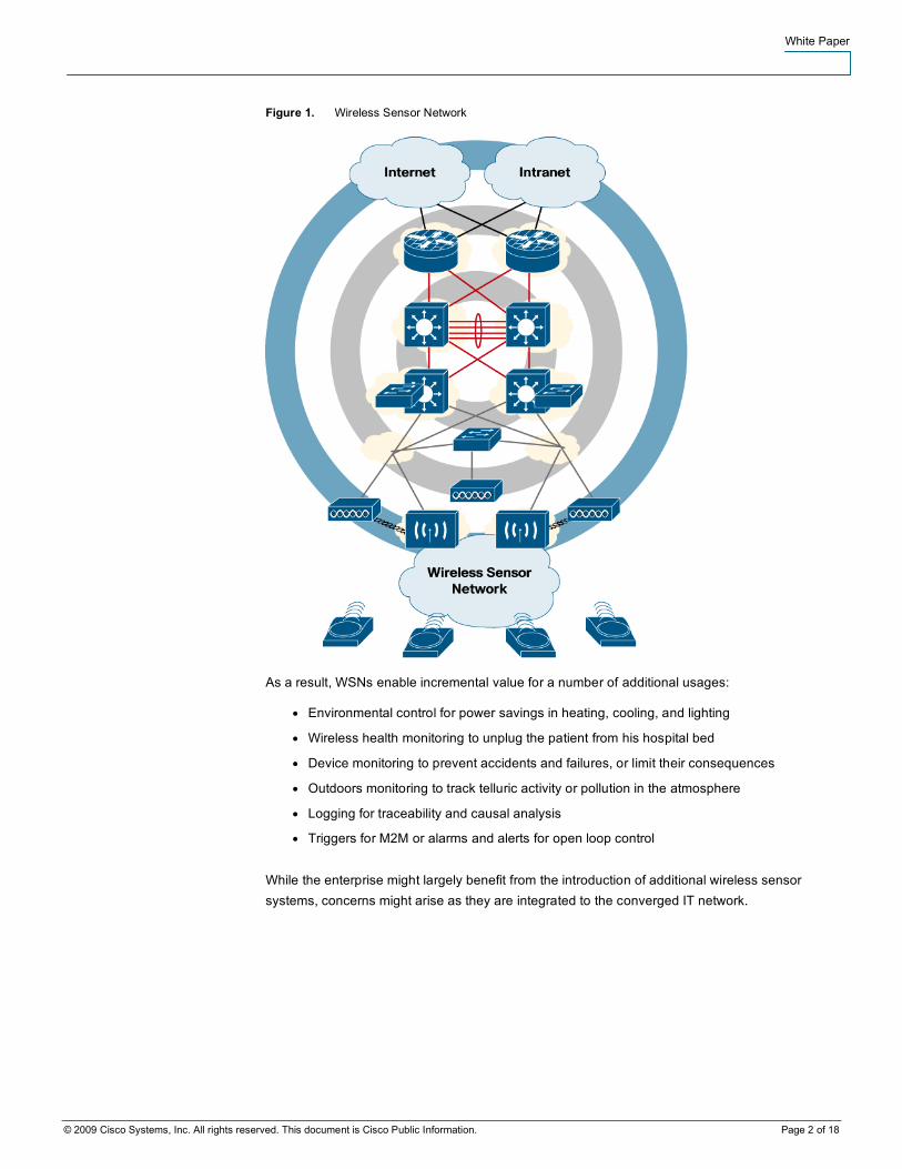
Figure 1. Wireless Sensor Network
As a result, WSNs enable incremental value for a number of additional usages:
● Environmental control for power savings in heating, cooling, and lighting
● Wireless health monitoring to unplug the patient from his hospital bed
● Device monitoring to prevent accidents and failures, or limit their consequences
● Outdoors monitoring to track telluric activity or pollution in the atmosphere
● Logging for traceability and causal analysis
● Triggers for M2M or alarms and alerts for open loop control
While the enterprise might largely benefit from the introduction of additional wireless sensor systems, concerns might arise as they are integrated to the converged IT network.
White Paper
© 2009 Cisco Systems, Inc. All rights reserved. This document is Cisco Public Information. Page 3 of 18
Coexistence
The IEEE 802.15.4 standard is the base for most WSN solutions that are proposed to the market today. Similarly, the 802.11 standard is the foundation for WLAN applications. Both standards exhibit low power bursting of energy and operate in the Industrial Scientific and Medical (ISM) band of 2.4 GHz band. This band is important due to multiple reasons. First, this band does not require the use of a governmental license for its usage in most regions of the world, providing global availability. Second, it is has a bandwidth of 83.5 MHz, wide enough for most WLAN and WSN applications. Finally, it features the best propagation characteristics available for international unlicensed bands.
Due to its features, the 2.4-GHz band provides an attractive medium for developing tethered-free applications based on current and future wireless standards. In addition to 802.15.4 and 801.11b/g, this band currently uses other standards such as 802.15.3, Bluetooth, and a multitude of proprietary digital and analog systems.
Since the 2.4-GHz band is a shared spectrum, coexistence between wireless services is relevant in order to ensure performance requirements. As defined by the IEEE, coexistence is the ability of one system to perform a task in a given shared environment where other systems have an ability to perform their tasks and may or may not be using the same set of rules.
Collisions and coexistence issues can happen when two or more packets overlap in both time and frequency with sufficient energy to interfere with one another. Coexistence effects can be measured by a variety of sophisticated methodologies, but in practice, the effects of coexistence can be measured simply by the end-to-end message delivery success rate and or latency for the relevant operational conditions—when multipath fading is made negligible.
Coexistence issues can not be eliminated but the effects can be limited by the use of a combination of mitigation techniques called diversity measures. These diversity techniques are discussed in the following sections.
Time Diversity
Time diversity is a technique where the data transmission is scheduled intelligently to minimize collisions and recover from losses. This can be achieved in many ways, including Forward Error Correction (FEC), Network Coding, Error Recovery Procedures (acknowledgements and retries), and Time-Division Multiplexing (TDM).
TDM is a synchronized system that reserves time slots for a specific communication link. This technique maximizes the packet success rate of wireless links by avoiding collisions with an impact on latency and throughput.
TDM is included in the recent Wireless HART standard and the upcoming ISA100.11a standard for Industrial Wireless Sensor Networks (I-WSN).
Coding Diversity
The Coding Diversity technique, widely used by CDM systems, allows effective use of the radio spectrum. With this method, a specific transmission can be easily separated from the noise of other communications occurring at the same time.
The IEEE 802.11b and 802.15.4 standards use Coding Diversity over the Direct Sequence Spread Spectrum (DSSS) system as a built-in coexistence measure that optimizes the performance when networks of both technologies are collocated.
White Paper
© 2009 Cisco Systems, Inc. All rights reserved. This document is Cisco Public Information. Page 4 of 18
Frequency Diversity
Frequency Diversity is a technique where the wireless devices can dynamically choose different channels of operation. This can occur periodically by the use of frequency hopping techniques (such as Bluetooth) or channel hopping (such as WirelessHART), or non-periodical, also called frequency dynamic system (such as ZigBee).
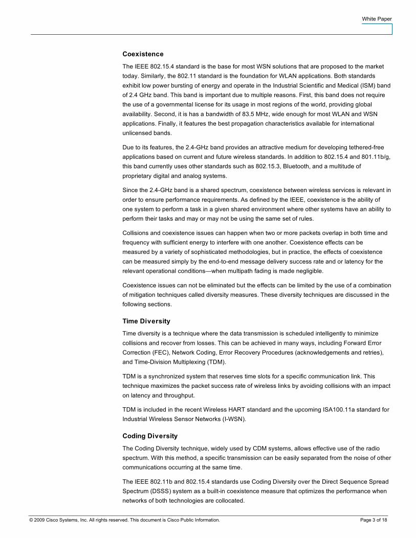
Figure 2. 802.11 and 802.15.4 Channel Allocation over the 2.4-GHz Band
Frequency diversity can be enhanced by the use of frequency blacklisting; that is, avoidance of a particular set of frequencies where another wireless system is operating or where interference was detected, for instance jamming from a microwave oven. It is important to note that many government regulations worldwide do not allow the use of frequency blacklisting to narrowband frequency hoppers systems.
As illustrated in Figure 2, the 802.11b/g and the 802.11.4 standards provide a channel allocation that enables non-overlapping channel assignments. This is another built-in coexistence measure that optimizes the performance when networks of both technologies are collocated and guarantees the robustness that I-WSN requires.
Path Diversity
Path diversity is enabled by the use of mesh networking. This technique is widely used by 802.15.4-based WSNs such as WirelessHART and ZigBee. The objective is to provide redundant communication paths for the communication between two or more wireless devices. In addition, this technique allows the use of lower power transmissions (enough to be heard by a neighbor router) which minimizes coexistence issues due to power jamming.
White Paper
© 2009 Cisco Systems, Inc. All rights reserved. This document is Cisco Public Information. Page 5 of 18
Power Diversity
Power diversity is performed by controlling the transmission power of radio links to the minimum level where destination devices can receive the signal, in order to limit the RF pollution against the other users of the spectrum.
It must be noted that the radius of interference grows faster with the transmit power than the radius of reception. For that reason, it is possible to obtain a better spatial density and throughput over a given area with RF power control—particularly low power—and routing/meshing than with high-power broadcasting.
Spatial Diversity
Space diversity consists in the careful location of wireless systems in space in a manner that minimizes coexistence issues with nearby wireless systems. In many cases this type of diversity is not practical unless network planning is executed during installation and/or addition of new devices or networks.
There are many variations of spatial diversity: Antenna diversity is the simplest instance where the receiver selects the best signal from multiple (usually two or three) antennas. 802.11n makes use of multiple-input multiple-output (MIMO) to add diversity to the transmit side.
Directional antennas and beam-forming antenna arrays focus the transmission over a specific sector and enable the reuse of the same channel at the same time on another sector.
Coexistence Strategy for 802.11 and 802.15.4
For 802.11b/g systems operating in the same environment as 802.15.4-based networks, a coexistence strategy can be established based on the use of the diversity measures described earlier:
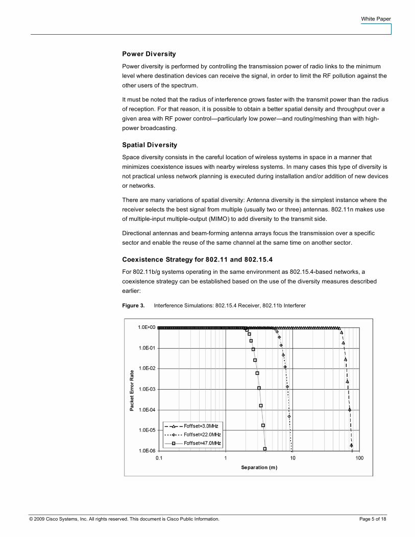
Figure 3. Interference Simulations: 802.15.4 Receiver, 802.11b Interferer
White Paper
© 2009 Cisco Systems, Inc. All rights reserved. This document is Cisco Public Information. Page 6 of 18
● Spatial Diversity: When deploying 802.11 and 802.15.4 radios that are not integrated or designed to be collocated, it is recommended to keep them separated by at least one meter. The error rate introduced by collocated emissions on an 802.15.4 receiver is illustrated in Figure 3: because it is simpler, 802.15.4 is usually the first impacted.
● Frequency Diversity: Use channel hopping when if available; otherwise, minimize the use of 802.15.4 channels which overlap with existing 802.11b/g channels or other 802.15.4 networks. In addition, favor the use of 802.15.4 channels that are located in low energy zone from the 802.11b/g non-overlapping channels and blacklist some channels to protect the part of the spectrum that is allocated to the other technology.
● A final coexistence measure is the one coming from the usage of standards-based technologies. IEEE 802 is composed of 2200 active engineers and scientists from all around the world. They are in charge of defining and maintaining communication standards that will coexist peacefully with 802.15.4 and 802.11. The IEEE 802 has an ongoing coexistence working group, which is actively providing advice to the rest of the committees to ensure that no new standard will cause a significant degradation to a previously defined one. Newer standards such as WirelessHART and ISA100.11a enhance the built-in coexistence properties of 802.15.4 by adding frequency and time diversity within the protocol.
Securing the Air
The IEEE 802.11 and IEEE 802.15.4 standards make use of AES-128 (Advanced Encryption Standard, with 128-bit keys and 128-bit block size) symmetric-key cryptography algorithm. The use of this sophisticated algorithm provides a robust, state-of-the-art message frame security. This core security mechanism is also used in conjunction with other security services to provide a complete wireless communications security suite with an equivalent or higher level of security performance than that provided by a wired communications system. This security service provides the following:
Data Confidentiality
Data confidentiality is provided through encryption using a symmetric cipher, in which the same key is used to encrypt plain text at the message source and then decrypt the resulting cipher text at the message destination. Devices without the key cannot decrypt the message.
Data Authenticity
Data authenticity, also called data integrity, is a service that enables a receiving device to detect the modification of a message by parties without the correct cryptographic
key, by appending a message integrity code (MIC) to the message. Data authenticity helps ensure that the source of information is known and trusted (tampering or modification of an incoming information message is detected).
Data Freshness
To avoid replay attacks, in which an old message is stored by a malicious entity without the cryptographic key and then replayed later, the data authentication service is combined with a data freshness service. This service is in charge of maintaining in memory an ordered message sequence counter that enables the detection of out-of-sequence messages.
It is important to note that even when wireless security continues to occupy a high level of concern among users of wireless systems, the issues surrounding communication security are well addressed with existing standards-based technologies.

White Paper
© 2009 Cisco Systems, Inc. All rights reserved. This document is Cisco Public Information. Page 7 of 18
The major security issues reported in the literature are mostly associated to breaches in the security policies caused by disgruntled employees, theft of access passwords, bad configuration of the network, and other breaches.
Network High Availability
A defect in sensors and actuators can block a manufacturing line, and process-control people are used to very strict criteria for high availability, and very quick reactivity upon problems. Five-nines availability, or 10 Defect Per Millions (DPMs), equate to 5 minutes of downtime for the installation per year, and six nines to only 30 seconds.
As the IT network is used to transport sensor data to a backend application, it must keep up with the initial process-control expectations.
High Availability in the Sensor Network
High availability for the sensor data starts in the sensor network. For mission-critical sensors, great care must be placed in the selection of the WSN technology for its resilience against interferences and its capability to maintain the mesh of sensors. Also, jamming from the outside should be alleviated by adequate shielding and proper distance from the potential location of an attacker.
Turnkey solution vendors already propose self-forming, self-healing networks with multiple paths to the sensor gateway that concentrates the traffic and connects to the IT network for higher availability. In the near future, standards such as SP-100 will provide a better guarantee for the reliability of the network.
High Availability for the Sensor Gateway
A gateway—also called manager—is usually deployed to interface the sensor world (for example, 802.15.4-based) and the IT network, whether wireless (802.11) or switched (Ethernet). In fact, the purpose of the gateway goes beyond switching packets. It is not unusual for the gateway to perform such tasks as data aggregation, logging, offline routing server, and application server for dedicated applications, and to be used to reprogram or reconfigure the sensors.
This gateway device might represent a single point of failure for the sensors that it controls. It is thus critical for high availability of the whole sensor network to ensure that a hot-standby backup device is deployed if the WSN vendor supports that feature and that it is powered by a safe source like a UPS.
If the gateway is connected to a wired switched backbone, Power over Ethernet (PoE) from a switch that is on UPS can guarantee the continuity of the power source:
● Cisco® pre-standard devices initially receive 6.3 watts (W) and then optionally negotiate via Cisco Discovery Protocol.
● 802.3af devices initially receive 12.95W, unless the power sourcing equipment is able to detect the power classification for a specific power device.
White Paper
© 2009 Cisco Systems, Inc. All rights reserved. This document is Cisco Public Information. Page 8 of 18
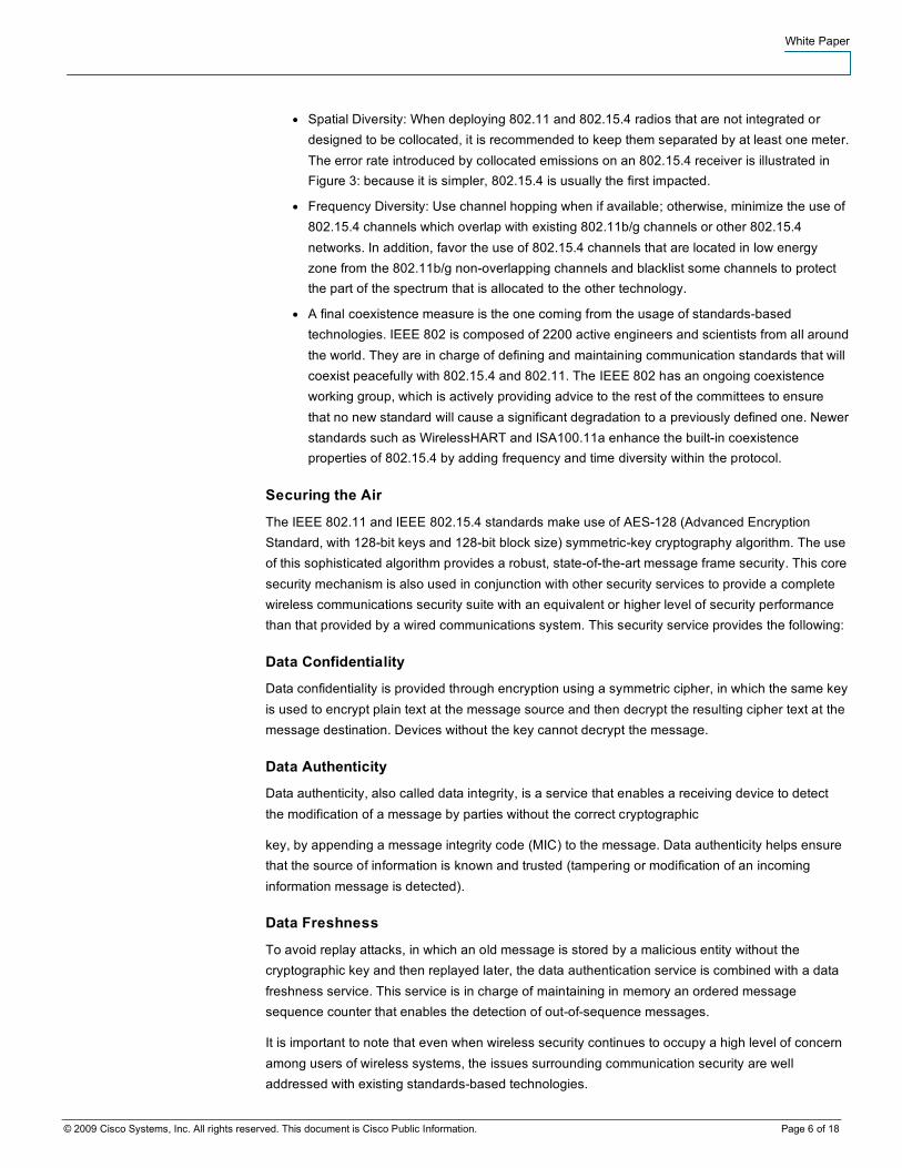
Building a Highly Available Converged Campus Network
People from a different environment might underestimate the efforts of the IT department to ensure more than fives nines of reliability, availability, and serviceability for critical applications such as medical, financial, and unified communication across the campus. Cisco has been supporting that effort by proposing a number of reference designs to match these high-availability requirements. Those models exploit standard protocols and advanced techniques such as fast rerouting and load balancing:
● Layer 3 routing protocol features:
◦ Nonstop Forwarding (NSF)
◦ Stateful Switchover (SSO)
● Layer 2 redundancy—Spanning Tree Protocol: PVST+ and Spanning Tree Protocol (802.1D-1998)
◦ Rapid PVST+ - RSTP (802.D-2004)
● Trunking protocols (isl/802.1Q)
● Unidirectional link detection
● Load balancing
◦ EtherChannel link aggregation
◦ CEF equal cost load balancing
● First-hop redundancy protocols:
◦ VRRP, HSRP, and GLBP
In the reference designs, the network is architected in three layers:
● The access layer includes both switched and highly available wireless Access, with full redundancy to react rapidly upon a link or a device failure. Typical features at that layer include inline power (PoE), QoS scheduling, trust boundary and packet classification. Fast convergence is provided at Layer 2 by rapid Spanning Tree Protocol and at Layer 3 by tuning of improved routing protocols.
● The distribution layer aggregates Layer 2 traffic from multiple Access layer switches and terminates VLANs and subnets; this layer provides Policy enforcement, QoS scheduling, trust boundary and packet classification.
● The core layer is a Layer 3 high-speed backbone for the campus network with low latency and high packet throughput; it might perform QoS scheduling and trust boundary.
Both the distribution and the core are engineered with redundant nodes and links to provide maximum redundancy and optimal convergence. Traditional reference designs propose variations of Multilayer Reference Designs with a Layer 2/3 distribution and a Layer 2 access layer. The Routed Access Design features a Layer 3 distribution with a Layer 3 access layer. Finally, the Virtual Switch Access-Distribution block design is introduced to optimize the link utilization and redundancy of a large Layer 2 access layer.
White Paper
© 2009 Cisco Systems, Inc. All rights reserved. This document is Cisco Public Information. Page 9 of 18
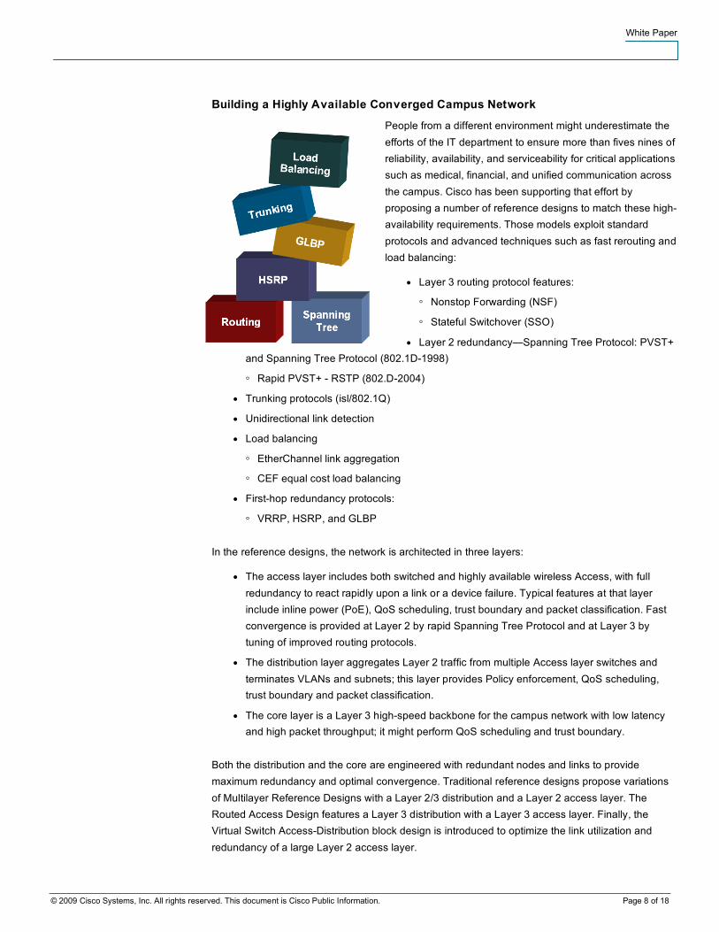
The Virtual Switch design merges the access switches into a virtual entity and aggregates the bandwidth of the redundant links into a multi-chassis EtherChannel (MEC) link.
Figure 4. Virtual Switch Design
With a single multi-chassis EtherChannel, the redundant links are used in a per-flow load-balancing fashion as opposed to traditional hot standby. This roughly doubles the access bandwidth, reduces the downtimes inherent to Spanning Tree Protocol re-computation and simplifies the configuration by eliminating the need for protocols like Hot Standby Router Protocol (HSRP) and Gateway Load Balancing Protocol (GLBP).
The Virtual Switch model thus increases the capacity of the access network and reduces its complexity. With that model, it is both safer and easier to span VLANs across a building, or a factory floor, even across a whole plant if necessary.
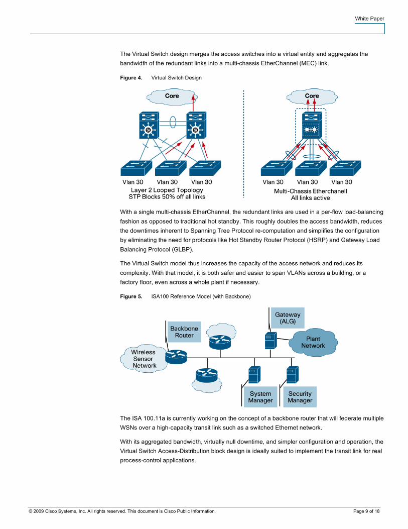
Figure 5. ISA100 Reference Model (with Backbone)
The ISA 100.11a is currently working on the concept of a backbone router that will federate multiple WSNs over a high-capacity transit link such as a switched Ethernet network.
With its aggregated bandwidth, virtually null downtime, and simpler configuration and operation, the Virtual Switch Access-Distribution block design is ideally suited to implement the transit link for real process-control applications.
White Paper
© 2009 Cisco Systems, Inc. All rights reserved. This document is Cisco Public Information. Page 10 of 18
Guaranteed Bandwidth and QoS
Quality of service (QoS) is the measure of transmission quality and service availability of a network (or internetworks). The transmission quality of the network is determined by the following factors: latency, jitter, and loss.
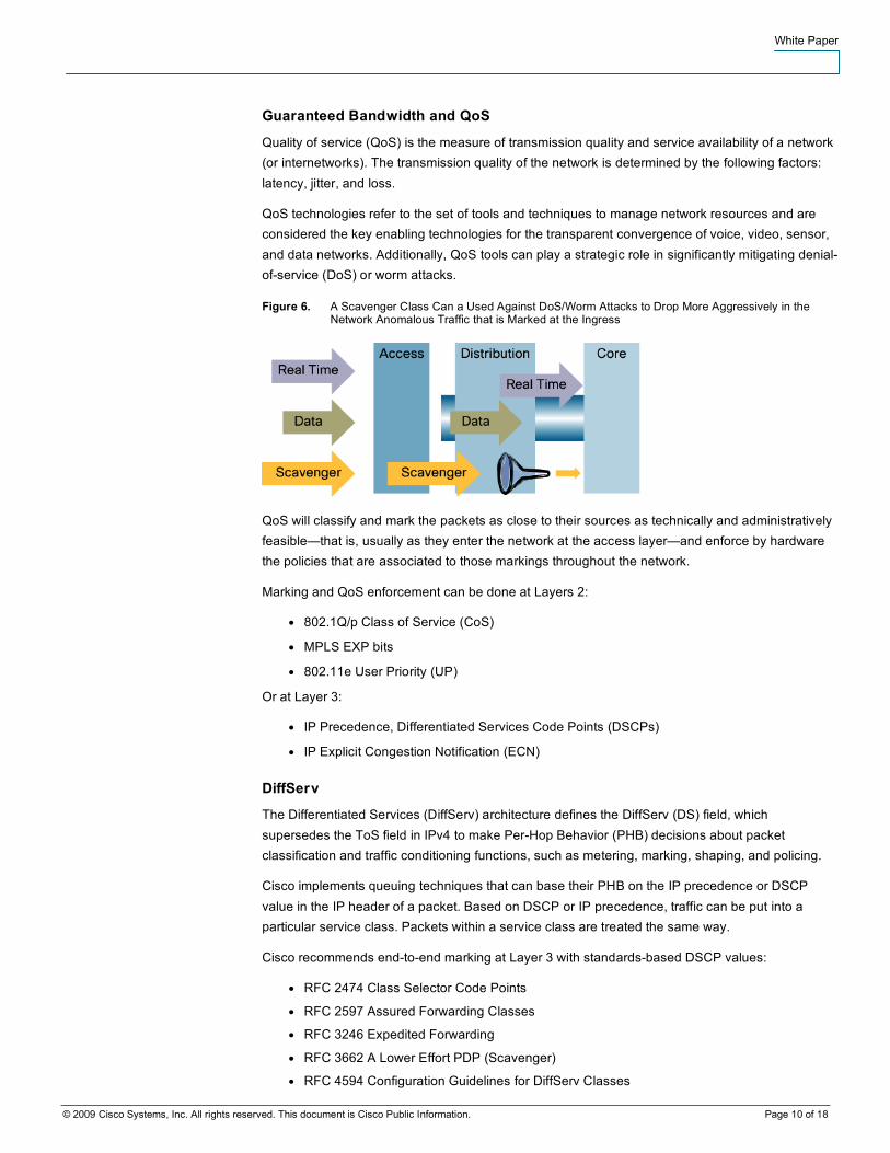
QoS technologies refer to the set of tools and techniques to manage network resources and are considered the key enabling technologies for the transparent convergence of voice, video, sensor, and data networks. Additionally, QoS tools can play a strategic role in significantly mitigating denial-of-service (DoS) or worm attacks.
Figure 6. A Scavenger Class Can a Used Against DoS/Worm Attacks to Drop More Aggressively in the Network Anomalous Traffic that is Marked at the Ingress
QoS will classify and mark the packets as close to their sources as technically and administratively feasible—that is, usually as they enter the network at the access layer—and enforce by hardware the policies that are associated to those markings throughout the network.
Marking and QoS enforcement can be done at Layers 2:
● 802.1Q/p Class of Service (CoS)
● MPLS EXP bits
● 802.11e User Priority (UP)
Or at Layer 3:
● IP Precedence, Differentiated Services Code Points (DSCPs)
● IP Explicit Congestion Notification (ECN)
DiffServ
The Differentiated Services (DiffServ) architecture defines the DiffServ (DS) field, which supersedes the ToS field in IPv4 to make Per-Hop Behavior (PHB) decisions about packet classification and traffic conditioning functions, such as metering, marking, shaping, and policing.
Cisco implements queuing techniques that can base their PHB on the IP precedence or DSCP value in the IP header of a packet. Based on DSCP or IP precedence, traffic can be put into a particular service class. Packets within a service class are treated the same way.
Cisco recommends end-to-end marking at Layer 3 with standards-based DSCP values:
● RFC 2474 Class Selector Code Points
● RFC 2597 Assured Forwarding Classes
● RFC 3246 Expedited Forwarding
● RFC 3662 A Lower Effort PDP (Scavenger)
● RFC 4594 Configuration Guidelines for DiffServ Classes
White Paper
© 2009 Cisco Systems, Inc. All rights reserved. This document is Cisco Public Information. Page 11 of 18
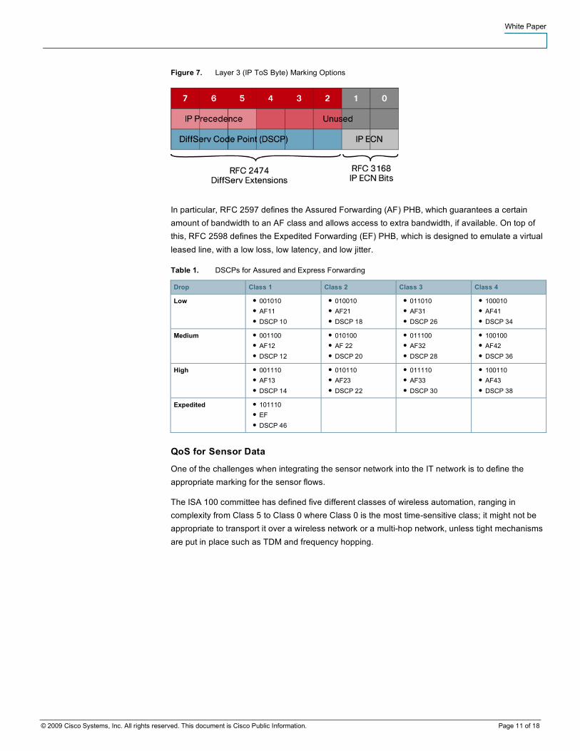
Figure 7. Layer 3 (IP ToS Byte) Marking Options
In particular, RFC 2597 defines the Assured Forwarding (AF) PHB, which guarantees a certain amount of bandwidth to an AF class and allows access to extra bandwidth, if available. On top of this, RFC 2598 defines the Expedited Forwarding (EF) PHB, which is designed to emulate a virtual leased line, with a low loss, low latency, and low jitter.
Table 1. DSCPs for Assured and Express Forwarding
Drop Class 1 Class 2 Class 3 Class 4
Low ● 001010 ● AF11 ● DSCP 10
● 010010 ● AF21 ● DSCP 18
● 011010 ● AF31 ● DSCP 26
● 100010 ● AF41 ● DSCP 34
Medium ● 001100 ● AF12 ● DSCP 12
● 010100 ● AF 22 ● DSCP 20
● 011100 ● AF32 ● DSCP 28
● 100100 ● AF42 ● DSCP 36
High ● 001110 ● AF13 ● DSCP 14
● 010110 ● AF23 ● DSCP 22
● 011110 ● AF33 ● DSCP 30
● 100110 ● AF43 ● DSCP 38
Expedited ● 101110 ● EF ● DSCP 46
QoS for Sensor Data
One of the challenges when integrating the sensor network into the IT network is to define the appropriate marking for the sensor flows.
The ISA 100 committee has defined five different classes of wireless automation, ranging in complexity from Class 5 to Class 0 where Class 0 is the most time-sensitive class; it might not be appropriate to transport it over a wireless network or a multi-hop network, unless tight mechanisms are put in place such as TDM and frequency hopping.
White Paper
© 2009 Cisco Systems, Inc. All rights reserved. This document is Cisco Public Information. Page 12 of 18
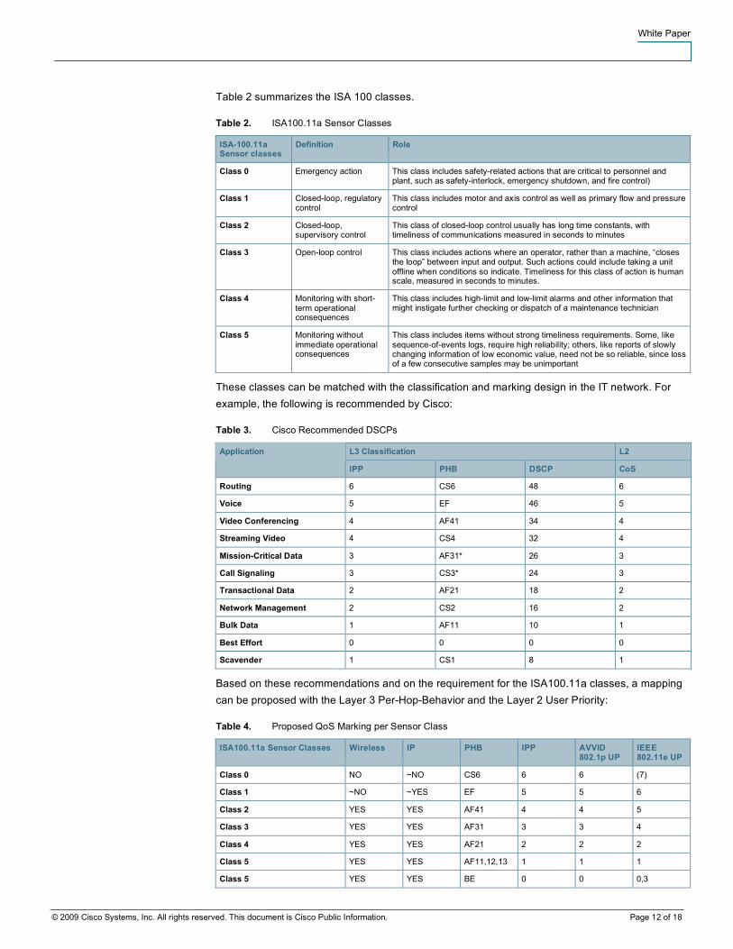
Table 2 summarizes the ISA 100 classes.
Table 2. ISA100.11a Sensor Classes
ISA-100.11a Sensor classes
Definition Role
Class 0 Emergency action This class includes safety-related actions that are critical to personnel and plant, such as safety-interlock, emergency shutdown, and fire control)
Class 1 Closed-loop, regulatory control
This class includes motor and axis control as well as primary flow and pressure control
Class 2 Closed-loop, supervisory control
This class of closed-loop control usually has long time constants, with timeliness of communications measured in seconds to minutes
Class 3 Open-loop control This class includes actions where an operator, rather than a machine, “closes the loop” between input and output. Such actions could include taking a unit offline when conditions so indicate. Timeliness for this class of action is human scale, measured in seconds to minutes.
Class 4 Monitoring with short-term operational consequences
This class includes high-limit and low-limit alarms and other information that might instigate further checking or dispatch of a maintenance technician
Class 5 Monitoring without immediate operational consequences
This class includes items without strong timeliness requirements. Some, like sequence-of-events logs, require high reliability; others, like reports of slowly changing information of low economic value, need not be so reliable, since loss of a few consecutive samples may be unimportant
These classes can be matched with the classification and marking design in the IT network. For example, the following is recommended by Cisco:
Table 3. Cisco Recommended DSCPs
L3 Classification L2 Application
IPP PHB DSCP CoS
Routing 6 CS6 48 6
Voice 5 EF 46 5
Video Conferencing 4 AF41 34 4
Streaming Video 4 CS4 32 4
Mission-Critical Data 3 AF31* 26 3
Call Signaling 3 CS3* 24 3
Transactional Data 2 AF21 18 2
Network Management 2 CS2 16 2
Bulk Data 1 AF11 10 1
Best Effort 0 0 0 0
Scavender 1 CS1 8 1
Based on these recommendations and on the requirement for the ISA100.11a classes, a mapping can be proposed with the Layer 3 Per-Hop-Behavior and the Layer 2 User Priority:
Table 4. Proposed QoS Marking per Sensor Class
ISA100.11a Sensor Classes Wireless IP PHB IPP AVVID 802.1p UP
IEEE 802.11e UP
Class 0 NO ~NO CS6 6 6 (7)
Class 1 ~NO ~YES EF 5 5 6
Class 2 YES YES AF41 4 4 5
Class 3 YES YES AF31 3 3 4
Class 4 YES YES AF21 2 2 2
Class 5 YES YES AF11,12,13 1 1 1
Class 5 YES YES BE 0 0 0,3
White Paper
© 2009 Cisco Systems, Inc. All rights reserved. This document is Cisco Public Information. Page 13 of 18
Flow Isolation
Whereas VLANs provide flow isolation across the access layer, Cisco Network Virtualization enables the isolation of the process-control flows across the entire enterprise network through the logical segmentation of the physical network.
A logical segment might represent a visitor network that is isolated for security reasons, a voice-over-IP (VoIP) network that is separated for QoS reasons, or simply different organizational units on a corporate-wide IT network that are kept apart in order to implement some corporate policies.
In a similar fashion, the virtualization technologies can apply to protect the sensor data as they transparently traverse the IT network between a factory plant and centralized business operation software via sensor middleware and process-control applications.
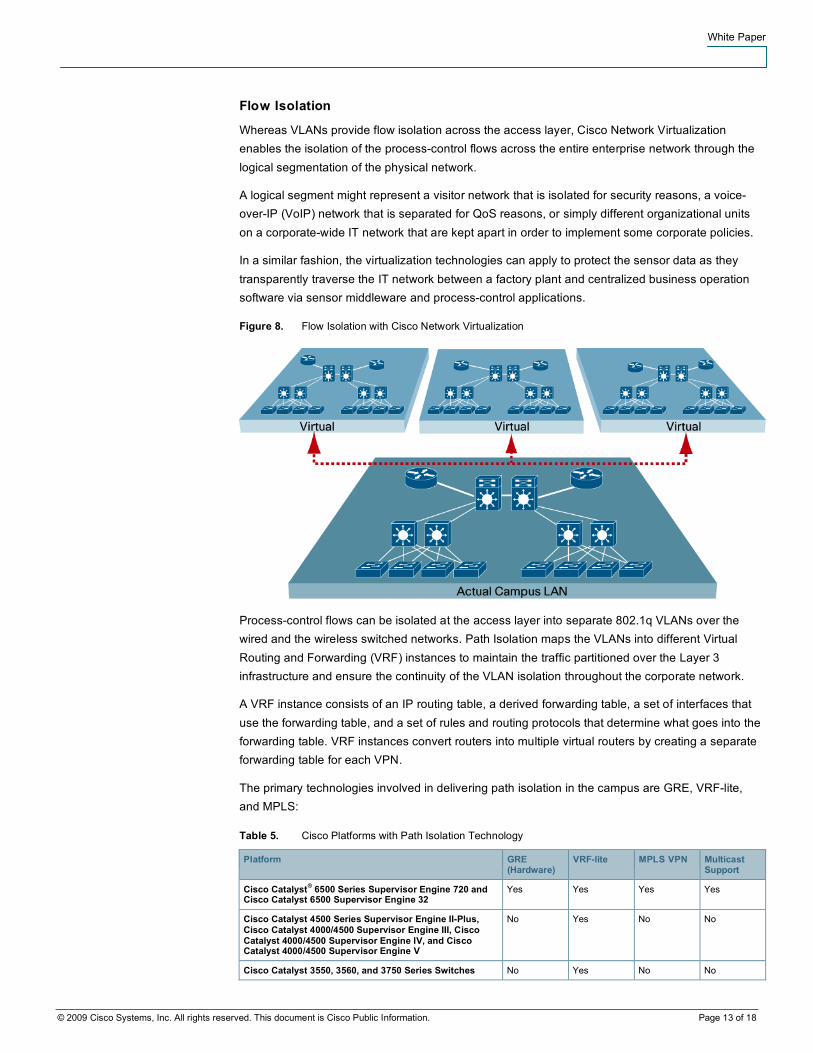
Figure 8. Flow Isolation with Cisco Network Virtualization
Process-control flows can be isolated at the access layer into separate 802.1q VLANs over the wired and the wireless switched networks. Path Isolation maps the VLANs into different Virtual Routing and Forwarding (VRF) instances to maintain the traffic partitioned over the Layer 3 infrastructure and ensure the continuity of the VLAN isolation throughout the corporate network.
A VRF instance consists of an IP routing table, a derived forwarding table, a set of interfaces that use the forwarding table, and a set of rules and routing protocols that determine what goes into the forwarding table. VRF instances convert routers into multiple virtual routers by creating a separate forwarding table for each VPN.
The primary technologies involved in delivering path isolation in the campus are GRE, VRF-lite, and MPLS:
Table 5. Cisco Platforms with Path Isolation Technology
Platform GRE (Hardware)
VRF-lite MPLS VPN Multicast Support
Cisco Catalyst® 6500 Series Supervisor Engine 720 and Cisco Catalyst 6500 Supervisor Engine 32
Yes Yes Yes Yes
Cisco Catalyst 4500 Series Supervisor Engine II-Plus, Cisco Catalyst 4000/4500 Supervisor Engine III, Cisco Catalyst 4000/4500 Supervisor Engine IV, and Cisco Catalyst 4000/4500 Supervisor Engine V
No Yes No No
Cisco Catalyst 3550, 3560, and 3750 Series Switches No Yes No No
White Paper
© 2009 Cisco Systems, Inc. All rights reserved. This document is Cisco Public Information. Page 14 of 18
GRE tunnels represent a fairly simple approach to creating a small number of closed user groups on the campus network. Rather than extending a VLAN across the network to interconnect a manufacturing plant and a sensor application, the process control traffic is instead isolated to a unique VRF at each distribution layer switch. The traffic is then transported across the corporate LAN through the GRE tunnel to a central device, such as an Internet edge switch.
VRF-lite, a Cisco feature also known as multi-VRF customer edge, provides a solution for campus segmentation by enabling a single routing device to support multiple virtual routers. Each logical router contains its own set of interfaces as well as a routing table and a forwarding table. VRF-lite enables support for scenarios where IP addresses can be overlapped among the VPNs. Each VRF maintains an independent routing domain.
This flexibility enables the IT network to absorb an existing process-control network without the cumbersome tasks of renumbering, and enables both groups to manage their own address space independently.
Another way to segment a campus network for closed user groups is by overlaying MPLS-based, Layer 3 VPNs onto the routed infrastructure of the campus LAN. Like GRE tunnels and VRF-lite, MPLS VPNs provide a secure and dependable way to form logically separated networks on a common physical infrastructure. In MPLS, closed user groups are established through VPNs that are transported independently over the core of the network using labels.
The networkwide benefit of this approach is that any VPN can be configured to connect users and resources at any location in the network, without any compromises in performance or network design. Accordingly, MPLS VPNs are the most scalable of the three solutions for Cisco Network Virtualization discussed in this document.
Next-Generation Readiness with IPv6
Machine-to-machine (M2M) applications are one of the key business drivers for sensors. M2M covers a wide range of applications but in a typical scenario, a sensor detects an anomaly, sends an alert to a monitoring middleware which in turn generates a command to an actuator, informs a business operation software application, and eventually sends an alarm to an operator off the loop.
Scalability is critical for M2M. Soon, billions of sensor devices might be deployed to provide remote monitoring of houses, buildings, patient vital signs, physical security, and a number of new applications enabled by the plummeting price of the technology.
The Internet Protocol (IP) provides well-known and proven technology to reach the sensors from anywhere, at any point of time, even on the move. IP-based sensors can connect to IP-based networks without the need for intermediate entities like translation gateways or proxies.
White Paper
© 2009 Cisco Systems, Inc. All rights reserved. This document is Cisco Public Information. Page 15 of 18
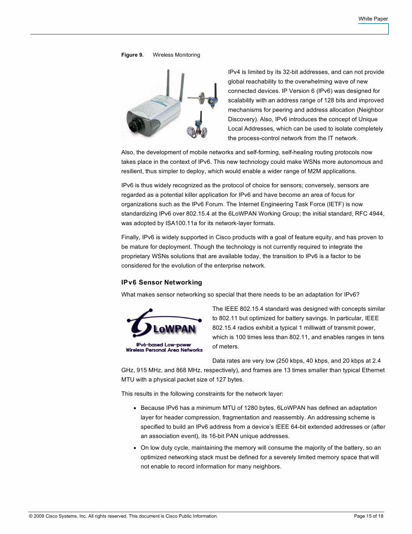
Figure 9. Wireless Monitoring
IPv4 is limited by its 32-bit addresses, and can not provide global reachability to the overwhelming wave of new connected devices. IP Version 6 (IPv6) was designed for scalability with an address range of 128 bits and improved mechanisms for peering and address allocation (Neighbor Discovery). Also, IPv6 introduces the concept of Unique Local Addresses, which can be used to isolate completely the process-control network from the IT network.
Also, the development of mobile networks and self-forming, self-healing routing protocols now takes place in the context of IPv6. This new technology could make WSNs more autonomous and resilient, thus simpler to deploy, which would enable a wider range of M2M applications.
IPv6 is thus widely recognized as the protocol of choice for sensors; conversely, sensors are regarded as a potential killer application for IPv6 and have become an area of focus for organizations such as the IPv6 Forum. The Internet Engineering Task Force (IETF) is now standardizing IPv6 over 802.15.4 at the 6LoWPAN Working Group; the initial standard, RFC 4944, was adopted by ISA100.11a for its network-layer formats.
Finally, IPv6 is widely supported in Cisco products with a goal of feature equity, and has proven to be mature for deployment. Though the technology is not currently required to integrate the proprietary WSNs solutions that are available today, the transition to IPv6 is a factor to be considered for the evolution of the enterprise network.
IPv6 Sensor Networking
What makes sensor networking so special that there needs to be an adaptation for IPv6?
The IEEE 802.15.4 standard was designed with concepts similar to 802.11 but optimized for battery savings. In particular, IEEE 802.15.4 radios exhibit a typical 1 milliwatt of transmit power, which is 100 times less than 802.11, and enables ranges in tens of meters.
Data rates are very low (250 kbps, 40 kbps, and 20 kbps at 2.4 GHz, 915 MHz, and 868 MHz, respectively), and frames are 13 times smaller than typical Ethernet MTU with a physical packet size of 127 bytes.
This results in the following constraints for the network layer:
● Because IPv6 has a minimum MTU of 1280 bytes, 6LoWPAN has defined an adaptation layer for header compression, fragmentation and reassembly. An addressing scheme is specified to build an IPv6 address from a device’s IEEE 64-bit extended addresses or (after an association event), its 16-bit PAN unique addresses.
● On low duty cycle, maintaining the memory will consume the majority of the battery, so an optimized networking stack must be defined for a severely limited memory space that will not enable to record information for many neighbors.
White Paper
© 2009 Cisco Systems, Inc. All rights reserved. This document is Cisco Public Information. Page 16 of 18
● Idle listening might cost more that actual transmitting unless the communications between peer radios are synchronized. Because of the interferences between sensors, a WSN-wide TDM plan might be required.
● Path Selection involves not only the quality of signal between the nodes on the way but also whether individual nodes are battery- or even solar-powered, which turns into an expectation of whether a node will be available to forward a packet should the packet reach it in spite of all interferences.
At the moment, the multi-hop protocols in the mesh and sensor network research community are proprietary and operate at Layer 2, forming homogeneous but non-interoperable islands on the overall network. It might be required to deploy multiple overlaid sensor networks in order to get the full set of measures that are needed in a given deployment, and the integration of a next generation is not guaranteed.
6LoWPAN provides a compressed header format for "mesh routing" that can be leveraged by further work for an interoperable Layer 3 wireless sensor routing protocol. The work has started at the IETF in the context of the ROLL Working Group on behalf of 6LoWPAN, which now concentrates on porting Neighbour Discovery onto 802.15.4.
Industrial Wireless Sensor Networking
WirelessHART is the first industrial wireless sensor networking standard. This standard is part of the HART 7 specification ratified in July 2007. The HART Communication Foundation (HCF), a non-profit organization, is the standard setting body that promotes and maintains the HART specification. The HART Communication Protocol is one of the most-used industrial communications systems in the industrial plants.
The wireless technology that HART 7 provides enhances the capabilities of the current wired HART networks since it enables measurement of plant variables that were uneconomical or technically difficult to reach with conventional wired systems. At the same time, WirelessHART uses the traditional HART technology and products that are already in place by allowing these devices to be full participants in a wireless network.
WirelessHART was developed to address industrial applications such as critical data monitoring, calibration, device status and diagnostics, field device troubleshooting, commissioning, and supervisory process control. WirelessHART provides robust and reliable communication using DSSS channel hopping based on IEEE std. 802.15.4, TDM, redundant data paths (mesh), and retry mechanisms.
In addition to WirelessHART, there is an ongoing initiative led by the Instrumentation, System, and Automation Society (ISA) to develop an industrial wireless standard that addresses other industrial and commercial applications. The ISA 100.11a Working Group is in charge of defining a specification that includes security and management for wireless devices serving a wide range of application scenarios excluding mission-critical monitoring.
White Paper
© 2009 Cisco Systems, Inc. All rights reserved. This document is Cisco Public Information. Page 17 of 18
As in WirelessHART, the ISA 100.11a standard reuses and extends IEEE std. 802.15.4 2006 and uses its security part to address major industrial security threats. ISA 100.11a also extends 6LowPAN for QoS-aware relaying over multipath time-slotted meshes. A future release will incorporate the backbone router functionality that federates multiple Data Link Layer (radio) subnets into one larger ISA100.11a network. Related routing work has also started at the IETF within the ROLL Working Group.
Convergence work has started at ISA100 to improve inter-working with WirelessHART and offer a cohesive solution to the marketplace. As indicated earlier, both standards are based on the IEEE 802.15.4 radio and propose channel hopping, spread spectrum, and mesh networking technologies.
Conclusion
Cisco provides the technology and the reference designs that meet the industrial requirements in Security, Availability, Quality of Service and Flow Isolation, as well as pervasive support for IPv6 within its product lines. With these comprehensive offerings, Cisco enables the integration of WSNs within the enterprise network today, and prepares for the next generation of sensor networking and of IP networking in general.
With an emphasis in reliability and high levels of security, Emerson Process Management provides standard-based, self-organizing industrial WSNs. This technology enables the wireless networking of a wide variety of Emerson’s field monitoring devices, such as temperature, pressure, flow, corrosion, and others.
With solid, proven standards and the commitment and leadership of companies such as Emerson and Cisco, industrial wireless sensors are a reality. The technologies and strategies to mitigate coexistence and security issues and
maximize network availability while maintaining a defined QoS are well documented and specified in the existing standards.
References
IEEE 802.11 Working Group (2007-06-12). IEEE 802.11-2007: Wireless LAN Medium Access Control (MAC) and Physical Layer (PHY) Specifications. ISBN 0-7381-5656-9.
IEEE Std 802.15.4™-2006, IEEE Standard for Information technology—Telecommunications and information exchange between systems—Local and metropolitan area networks—Specific requirements—Part 15.4: Wireless Medium Access Control (MAC) and Physical Layer (PHY) Specifications for Low-Rate Wireless Personal Area Networks (WPANs).
HART Communication Foundation. (2007). HART Field Communications Protocol Specification, Revision 7.0 (HCF_SPEC-13). Austin, TX USA.
HART Communication Foundation. (2007). Wireless Devices Specification. Rev6.0 5 September, 2007(HCF_SPEC-290). Austin, TX USA.
Gutierrez, J.A., Callaway, E. Barrett, R., “Low Rate Wireless Personal Area Networks: Enabling Wireless Sensors with IEEE 802.15.4”, IEEE Press, 2nd. Edition, 2007.
White Paper
© 2009 Cisco Systems, Inc. All rights reserved. This document is Cisco Public Information. Page 18 of 18
U.S. Department of Commerce, National Institute of Standards and Technology, Specification for the Advanced Encryption Standard (AES). Federal Information Processing Standards Publication 197. November 26, 2001. http://csrc.nist.gov/publications/fips/fips197/fips-197.pdf.
Kushalnagar, N., Montenegro, G., and C. Schumacher,
"IPv6 over Low-Power Wireless Personal Area Networks (6LoWPANs): Overview, Assumptions, Problem Statement, and Goals", RFC 4919, August 2007. http://tools.ietf.org/html/rfc4919.
Montenegro, G., Kushalnagar, N., Hui, J., and D. Culler, "Transmission of IPv6 Packets over IEEE 802.15.4 Networks", RFC 4944, September 2007. http://tools.ietf.org/html/rfc4944.
Zach Shelby & al., “Neighbor Discovery for 6LoWPAN”, http://tools.ietf.org/html/draft-ietf-6lowpan-nd
Network Virtualization—Path Isolation Design Guide. http://www.cisco.com/univercd/cc/td/doc/solution/pthisoex.pdf.
Design Best Practices for Latency Optimization. http://www.cisco.com/univercd/cc/td/doc/solution/latency.pdf.
Cisco Catalyst 6500: Virtual Switching System 1440. http://www.cisco.com/en/US/prod/collateral/switches/ps5718/ps9336/product_at_a_glance0900aecd806ee2d4.pdf.
Printed in USA C11-503160-01 04/09