integrating microstation & autocad in the workplace greg wallace mw1bp519
TRANSCRIPT
Integrating MicroStation & AutoCAD in the WorkplaceGreg Wallace
MW1BP519

MicroStation and AutoCAD
Why cant we all just get along?
NOW WE CAN !

Integration-Know the CAD file formats
Reference (XREF) MethodsText Styles – Attributed TextLine Styles – What works and what doesn’tClip MaskPlot Styles

Integration - Know the Client Standards
Version Layer Symbology Structure Line Styles Text Styles Dimension Styles Plot Styles Sheet Borders & Attributed Text
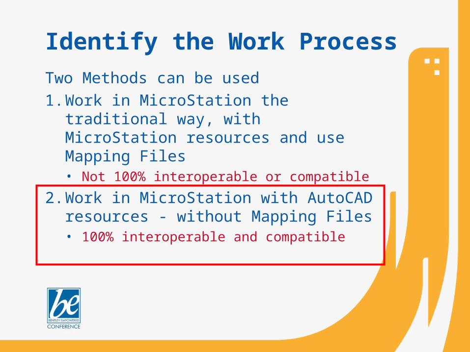
Identify the Work Process
Two Methods can be used
1. Work in MicroStation the traditional way, with MicroStation resources and use Mapping Files• Not 100% interoperable or compatible
2. Work in MicroStation with AutoCAD resources - without Mapping Files• 100% interoperable and compatible

CAD Workflow – Deliver DGN
V8 DGN WorkmodeAutoCAD Color TableAutoCAD Line StylesAutoCAD Text StylesAutoCAD Plot Styles
Deliver DGNUsing DWGAttachments
Start with DGN Edit DGN

CAD Workflow – Deliver DWG
V8 DGN WorkmodeAutoCAD Color TableAutoCAD Line StylesAutoCAD Text StylesAutoCAD Plot Styles
Start with DGN Edit DGNUsing DGN
Or DWGAttachments
Convert and DeliverDWG with completeReference structureIn place. No mapping of DGN resources required when usingAutoCAD resources.

CAD Workflow – Deliver DWG
V8 DWG WorkmodeAutoCAD Color TableAutoCAD Line StylesAutoCAD Text StylesAutoCAD Plot Styles
Start with DWG Edit DWGUsing DWGAttachments
Deliver DWG
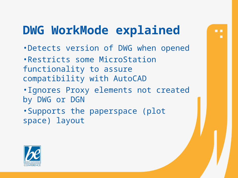
DWG WorkMode explained•Detects version of DWG when opened•Restricts some MicroStation functionality to assure compatibility with AutoCAD•Ignores Proxy elements not created by DWG or DGN•Supports the paperspace (plot space) layout

CAD Workflow -AutoCAD
Start with DWG Edit DWG Deliver DWG
Using AutoCAD

Know the Work FlowStart Edit Deliver
Start with DGN, Edit DGN, Deliver DWG. Using V8 DGN WorkMode
Start with DWG, Edit DWG, Deliver DWG. Using V8 DWG WorkMode
Start with DGN, Edit DGN, Deliver DGN. Using DWG Attachments
Start with DWG, Edit DWG, Deliver DWG. Using AutoCAD
Mic
roS
tatio
nA
utoC
AD

Line Styles
Only custom line styles are allowed in the DWG Workmode
AutoCAD doesn’t recognize MicroStation Line Styles 1-7.
AutoCAD may not recognize MicroStation Line Styles from a MicroStation .RSC file

Line Styles – Build in Line Definition File
*FUEL_EX_ABDD,Fuel Ex AbandA,.25,[EX_ABDD,DTE.shx,s=1],.375,-.125,["FUEL",Standard,x=-.02,y=-.05,s=.1],-.45,.25,[EX_ABDD,DTE.shx,s=1],.375,-.125
*FUEL_EX_TB_ABDD,Fuel Ex to be AbandA,.25,[EX_TB_ABDD,DTE.shx,s=1],.375,-.125,["FUEL",Standard,x=-.02,y=-.05,s=.1],-.45,.25,[EX_TB_ABDD,DTE.shx,s=1],.375,-.125

Client limit of 1-Sheet File per Drawing
AutoCAD limit of 1-Sheet Model per fileFile A
Master XREFAttachment
PaperSpacePaperSpacePaperSpace
ModelSpace
File BSub XREF
Attachment
File CSub XREF
Attachment
File C1Sub XREF
Attachment
File DSub XREF
Attachment
File D1Sub XREFOverlay
File D1 Cut off at XREF D
XREF Structure - AutoCAD
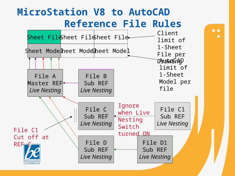
File AMaster REFLive Nesting
File BSub REF
Live Nesting
File CSub REF
Live Nesting
File D1Sub REF
Live Nesting
File DSub REF
Live Nesting
Client limit of 1-Sheet File per DrawingSheet ModelSheet Model
Sheet File
Sheet Model
Sheet File Sheet File
AutoCAD limit of 1-Sheet Model per file
Ignore when Live Nesting Switch turned ON
File C1Sub REF
Live NestingFile C1 Cut off at REF C
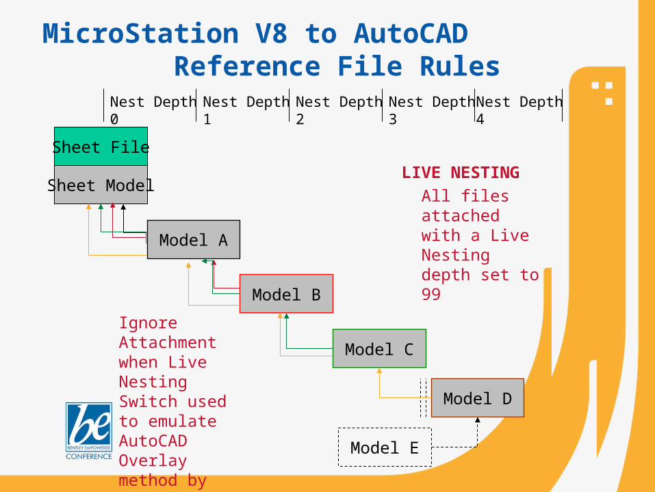
MicroStation V8 to AutoCADReference File Rules
Sheet File
Sheet Model
Ignore Attachment when Live Nesting Switch used to emulate AutoCAD Overlay method by restricting forward direction
All files attached with a Live Nesting depth set to 99
LIVE NESTING
MicroStation V8 to AutoCADReference File Rules
Model A
Nest Depth 0
Model E
Model B
Nest Depth 1
Model C
Nest Depth 2 Nest Depth 4Nest Depth 3
Model D

All files attached with Nest Depth set to 99
Default Model B(can also be any model)
Sheet Model A(can also be any model)
Default Model C(can also be any model)
Default Model D(can also be any model)
Direct Attachment Nest Depth 2
Direct Attachment Nest Depth 1
Direct Attachment Nest Depth 0
MicroStation V8 to AutoCADReference File Rules

Sheet File
Sheet Model
Only Master Reference file display and level display can be controlled through Level Manager in the Sheet Model
Using a Master Ref with Sub Ref attachments allows maximum control of files without having to enter each file interactively to make changes
Master Ref
Sub Ref
Sub Ref
Sub Ref
All file displays, level settings and clip boundaries of Sub Refs are controlled by settings in Master Ref
Reference File Rules - Controlling the Display

No Nesting – makes the attachments a Direct Attachment (nest depth=0) (not used at DTE)
Live Nesting – enables the live nesting functionality and allows you to set a Nesting Depth (99)
Copy Attachment
MicroStation to AutoCADDGN Referencing DGN or DWG

Attachment Level shall be set to Default for all Layers to Reference into Model as created
Live Nesting is only option allowed to emulate AutoCAD Attachment method
Ignore Attachment switch emulates AutoCAD Overlay method
DWGWorkMode
MicroStation V8DWG Referencing DWG

Integrating MicroStation & AutoCAD in the Workplace
Total FlexibilityTotal CompatibilityEnhanced capability with MicroStation XM
Greg WallaceCAD Manager – Bechtel Infrastructure