integrating systems safety into systems engineering during...
TRANSCRIPT
25th Annual INCOSE International Symposium (IS2015) Seattle, WA, July 13 – July 16, 2015
Integrating Systems Safety into Systems Engineering during Concept Development Cody Harrison Fleming
Aeronautics and Astronautics Massachusetts Institute of Technology
77 Massachusetts Avenue, 33-407C Cambridge, MA 02139
Nancy Leveson Professor, Aeronautics and Astronautics Massachusetts Institute of Technology
77 Massachusetts Avenue, 33-334 Cambridge, MA 02139
Copyright © 2015 by Cody Fleming. Published and used by INCOSE with permission.
Abstract. Safety should be designed into systems from their very conception,
which can be achieved by integrating powerful hazard analysis techniques into the general systems engineering process. The primary barrier to achieving this objective is the lack of effectiveness of the existing analytical tools during early concept development.
This paper introduces a new technique, which is based on a more powerful model of accident causality—called systems-theoretic accident model and process (STAMP)—that can capture behaviors that are prevalent in these complex, software-intensive systems. The goals are to (1) develop rigorous, systematic tools for the analysis of future concepts in order to identify potentially hazardous scenarios and undocumented assumptions, and (2) extend these tools to assist stakeholders in the development of concepts using a safety-driven approach.
Introduction Often the perception among engineers and other stakeholders is that safety is expensive.
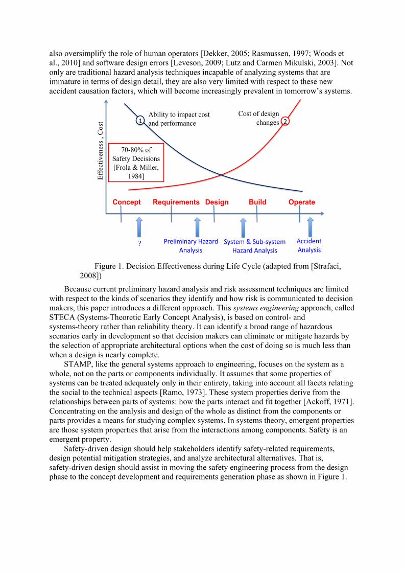
Safety-related features are also seen as intrusive because they seem to result in reduced performance, increased weight, or unnecessary complexity. In fact safety often is costly, both in terms of economics and technical performance, but this is not due to any intrinsic property of safety itself. Rather, the reason safety costs so much is that it is often considered only after the major architectural tradeoffs and design decisions have been made. Once the basic design is finalized, the only choice is to add expensive redundancy or excessive design margins [Leveson, 2009]. It has been estimated in the defense community that 70-80% of the decisions affecting safety are made in the early concept development stages of a project [Frola and Miller, 1984]. As Figure 1 illustrates, compensating later for making poor choices at the beginning can be very costly and ineffective. In fact, safety must be architected in to the system from the very beginning, just like other “ilities” or system properties [Boehm et al, 2002].
Unfortunately, as Figure 1 also depicts, traditional tools used for analyzing and improving safety are only applicable in the later stages of system development, when detailed design information is available. These same tools were developed long ago, when the primary cause of accidents was due to mechanical failure [Vesely et al., 1981]. Modern systems exhibit hazardous behavior due to a series of factors that extend well beyond hardware failure. The introduction of new technology, such as computers and software, is changing the types of accidents we see today [Leveson, 2012]. Hazardous behavior arises in systems due to unsafe interactions between components, even when the components have not necessarily failed. Given the complexity of today’s systems, these interactions are increasingly difficult to understand and predict. The underlying assumptions of traditional hazard analysis tools
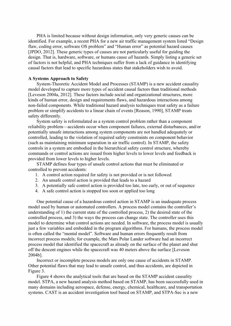
also oversimplify the role of human operators [Dekker, 2005; Rasmussen, 1997; Woods et al., 2010] and software design errors [Leveson, 2009; Lutz and Carmen Mikulski, 2003]. Not only are traditional hazard analysis techniques incapable of analyzing systems that are immature in terms of design detail, they are also very limited with respect to these new accident causation factors, which will become increasingly prevalent in tomorrow’s systems.
Figure 1. Decision Effectiveness during Life Cycle (adapted from [Strafaci,
2008]) Because current preliminary hazard analysis and risk assessment techniques are limited
with respect to the kinds of scenarios they identify and how risk is communicated to decision makers, this paper introduces a different approach. This systems engineering approach, called STECA (Systems-Theoretic Early Concept Analysis), is based on control- and systems-theory rather than reliability theory. It can identify a broad range of hazardous scenarios early in development so that decision makers can eliminate or mitigate hazards by the selection of appropriate architectural options when the cost of doing so is much less than when a design is nearly complete.
STAMP, like the general systems approach to engineering, focuses on the system as a whole, not on the parts or components individually. It assumes that some properties of systems can be treated adequately only in their entirety, taking into account all facets relating the social to the technical aspects [Ramo, 1973]. These system properties derive from the relationships between parts of systems: how the parts interact and fit together [Ackoff, 1971]. Concentrating on the analysis and design of the whole as distinct from the components or parts provides a means for studying complex systems. In systems theory, emergent properties are those system properties that arise from the interactions among components. Safety is an emergent property.
Safety-driven design should help stakeholders identify safety-related requirements, design potential mitigation strategies, and analyze architectural alternatives. That is, safety-driven design should assist in moving the safety engineering process from the design phase to the concept development and requirements generation phase as shown in Figure 1.
Concept Requirements Design Build Operate
Accident(Analysis(
Preliminary(Hazard(Analysis(
System(&(Sub7system(Hazard(Analysis(
10
(1( 2(Ability to impact cost and performance
Cost of design changes
Eff
ectiv
enes
s , C
ost
70-80% of Safety Decisions [Frola & Miller,
1984]
?(
Usual Characteristics of a Concept of Operations Though some of the concept generation and system architecting frameworks have
become increasingly formalized, the techniques still do not yield the level of detail necessary to perform most traditional types of hazard analysis [Harkleroad et al., 2013]. During concept development, the system is usually defined informally and many undocumented or implicit assumptions exist. A Concept of Operations (ConOps) can be developed in many different ways, but in general, it will include a statement of the goals and objectives of the system; strategies, tactics, policies, and constraints affecting the system; organizations, activities, and interactions among participants and operators; and operational processes for fielding the system [McGregor, 2005]. A ConOps “describes how the system will be operated during the life-cycle phases to meet stakeholder expectations. It describes the system characteristics from an operational perspective and helps facilitate an understanding of the system goals” [Kapurch, 2010].
The concept phase has the following characteristics: little design detail is available to analysts, engineering requirements do not yet exist, and descriptions of the system include informal, natural language text with many undocumented assumptions.
Traditional Approach to Early Safety Activities
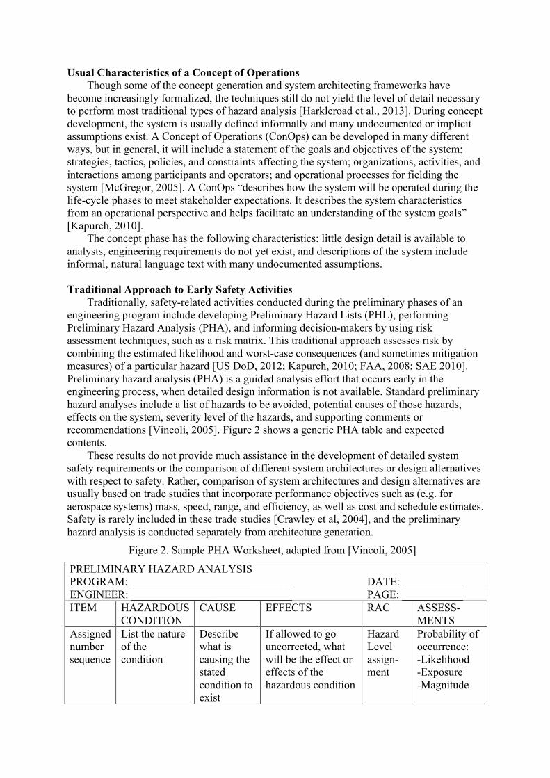
Traditionally, safety-related activities conducted during the preliminary phases of an engineering program include developing Preliminary Hazard Lists (PHL), performing Preliminary Hazard Analysis (PHA), and informing decision-makers by using risk assessment techniques, such as a risk matrix. This traditional approach assesses risk by combining the estimated likelihood and worst-case consequences (and sometimes mitigation measures) of a particular hazard [US DoD, 2012; Kapurch, 2010; FAA, 2008; SAE 2010]. Preliminary hazard analysis (PHA) is a guided analysis effort that occurs early in the engineering process, when detailed design information is not available. Standard preliminary hazard analyses include a list of hazards to be avoided, potential causes of those hazards, effects on the system, severity level of the hazards, and supporting comments or recommendations [Vincoli, 2005]. Figure 2 shows a generic PHA table and expected contents.
These results do not provide much assistance in the development of detailed system safety requirements or the comparison of different system architectures or design alternatives with respect to safety. Rather, comparison of system architectures and design alternatives are usually based on trade studies that incorporate performance objectives such as (e.g. for aerospace systems) mass, speed, range, and efficiency, as well as cost and schedule estimates. Safety is rarely included in these trade studies [Crawley et al, 2004], and the preliminary hazard analysis is conducted separately from architecture generation.
Figure 2. Sample PHA Worksheet, adapted from [Vincoli, 2005]
PRELIMINARY HAZARD ANALYSIS PROGRAM: _____________________________ DATE: ___________ ENGINEER: _____________________________ PAGE: ___________ ITEM HAZARDOUS
CONDITION CAUSE EFFECTS RAC ASSESS-
MENTS Assigned number sequence
List the nature of the condition
Describe what is causing the stated condition to exist
If allowed to go uncorrected, what will be the effect or effects of the hazardous condition
Hazard Level assign- ment
Probability of occurrence: -Likelihood -Exposure -Magnitude
PHA is limited because without design information, only very generic causes can be
identified. For example, a recent PHA for a new air traffic management system listed “Design flaw, coding error, software OS problem” and “Human error” as potential hazard causes [JPDO, 2012]. These generic types of causes are not particularly useful for guiding the design. That is, hardware, software, or humans cause all hazards. Simply listing a generic set of factors is not helpful, and PHA techniques suffer from a lack of guidance in identifying causal factors that lead to specific hazardous states that stakeholders wish to avoid.
A Systems Approach to Safety
System-Theoretic Accident Model and Processes (STAMP) is a new accident causality model developed to capture more types of accident causal factors than traditional methods [Leveson 2004a, 2012]. These factors include social and organizational structures, more kinds of human error, design and requirements flaws, and hazardous interactions among non-failed components. While traditional hazard analysis techniques treat safety as a failure problem or simplify accidents to a linear chain of events [Reason, 1990], STAMP treats safety differently.
System safety is reformulated as a system control problem rather than a component reliability problem—accidents occur when component failures, external disturbances, and/or potentially unsafe interactions among system components are not handled adequately or controlled, leading to the violation of required safety constraints on component behavior (such as maintaining minimum separation in air traffic control). In STAMP, the safety controls in a system are embodied in the hierarchical safety control structure, whereby commands or control actions are issued from higher levels to lower levels and feedback is provided from lower levels to higher levels.
STAMP defines four types of unsafe control actions that must be eliminated or controlled to prevent accidents:
1. A control action required for safety is not provided or is not followed 2. An unsafe control action is provided that leads to a hazard 3. A potentially safe control action is provided too late, too early, or out of sequence 4. A safe control action is stopped too soon or applied too long One potential cause of a hazardous control action in STAMP is an inadequate process
model used by human or automated controllers. A process model contains the controller’s understanding of 1) the current state of the controlled process, 2) the desired state of the controlled process, and 3) the ways the process can change state. The controller uses this model to determine what control actions are needed. In software, the process model is usually just a few variables and embedded in the program algorithms. For humans, the process model is often called the “mental model”. Software and human errors frequently result from incorrect process models; for example, the Mars Polar Lander software had an incorrect process model that identified the spacecraft as already on the surface of the planet and shut off the descent engines while the spacecraft was 40 meters above the surface [Leveson 2004b].
Incorrect or incomplete process models are only one cause of accidents in STAMP. Other potential flaws that may lead to unsafe control, and thus accidents, are depicted in Figure 3.
Figure 4 shows the analytical tools that are based on the STAMP accident causality model. STPA, a new hazard analysis method based on STAMP, has been successfully used in many domains including aerospace, defense, energy, chemical, healthcare, and transportation systems. CAST is an accident investigation tool based on STAMP, and STPA-Sec is a new
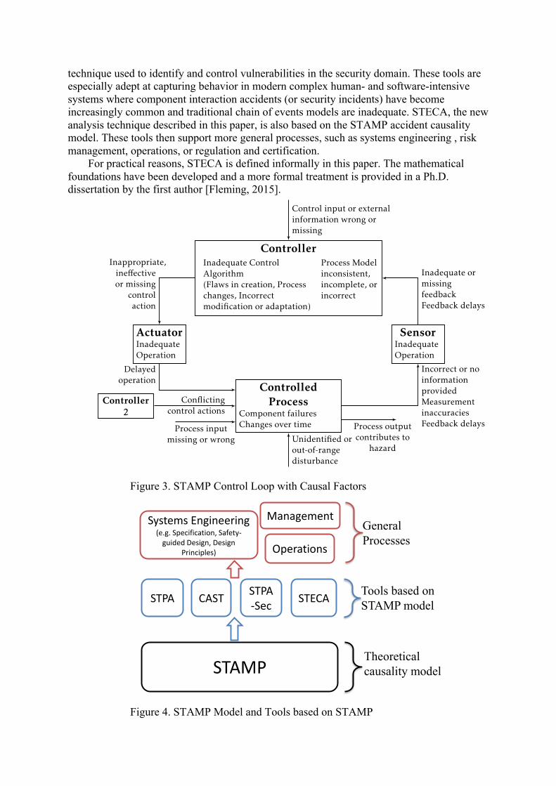
technique used to identify and control vulnerabilities in the security domain. These tools are especially adept at capturing behavior in modern complex human- and software-intensive systems where component interaction accidents (or security incidents) have become increasingly common and traditional chain of events models are inadequate. STECA, the new analysis technique described in this paper, is also based on the STAMP accident causality model. These tools then support more general processes, such as systems engineering , risk management, operations, or regulation and certification.
For practical reasons, STECA is defined informally in this paper. The mathematical foundations have been developed and a more formal treatment is provided in a Ph.D. dissertation by the first author [Fleming, 2015].
Figure 3. STAMP Control Loop with Causal Factors
Figure 4. STAMP Model and Tools based on STAMP
ControllerInadequate ControlAlgorithm(Flaws in creation, Processchanges, Incorrectmodification or adaptation)
Process Modelinconsistent,incomplete, orincorrect
ActuatorInadequateOperation
ControlledProcess
Component failuresChanges over time
SensorInadequateOperation
Controller2
Inappropriate,ine↵ectiveor missing
controlaction
Delayedoperation
Incorrect or noinformationprovidedMeasurementinaccuraciesFeedback delays
Inadequate ormissingfeedbackFeedback delays
Control input or externalinformation wrong ormissing
Unidentified orout-of-rangedisturbance
Conflictingcontrol actions
Process inputmissing or wrong
Process outputcontributes to
hazard
Figure 8: STPA Control Loop with Causal Factors
quirements flaws, design errors, complex human behavior, and component failures
[Leveson, 2012]. While many hazard analysis techniques stop once a sequence of
events or failures has been identified, STPA helps explain the complex reasons why
a sequence of events might occur, including underlying processes and control flaws
that may exist without any component failure.
Although STPA is relatively new compared to traditional methods, it has been demon-
strated successfully on a wide range of systems including aviation [Fleming et al.,
2013], spacecraft [Ishimatsu et al., 2010; Nakao et al., 2012; Fleming et al., 2012],
missile defense systems [Pereira et al., 2006], civil infrastructure [Dong, 2012], and
others.
However, STPA has only been applied to existing, operational systems or to projects
with a significant amount of design detail, although Harkleroad et al. [2013] iden-
tified it as a potentially e↵ective method during concept development. In addition,
56
STAMP
STPA CAST STPA-Sec STECA Tools based on
STAMP model
Theoretical causality model
Systems Engineering (e.g. Specification, Safety-
guided Design, Design Principles)
Management
Operations
General Processes
Systems-Theoretic Early Concept Analysis The early phases of systems engineering involve identifying system objectives and
criteria, defining top-level requirements, defining a system-level architecture, and then performing trade studies that ultimately lead to a design [e.g. Kapurch, 2010; INCOSE, 2011]. Table 1 depicts the relationships between safety-driven design activities and their counterparts in general systems engineering.
Table 1. General Systems Engineering and Safety-Driven Design
General Systems Engineering ⇔ Safety-Driven Design Identify System Objectives, Criteria ⇔ Identify Accidents and Hazards
Define Requirements ⇔ Define Safety Constraints Define a System Architecture ⇔ Define a Hierarchical Safety Control Structure
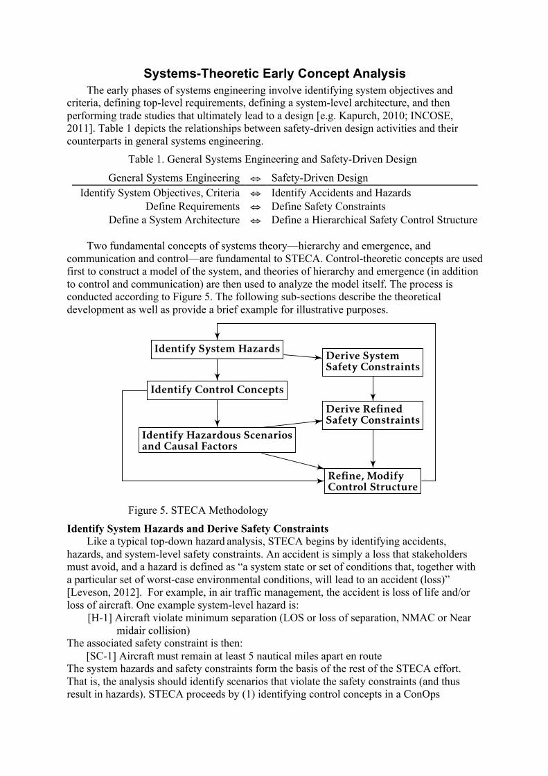
Two fundamental concepts of systems theory—hierarchy and emergence, and
communication and control—are fundamental to STECA. Control-theoretic concepts are used first to construct a model of the system, and theories of hierarchy and emergence (in addition to control and communication) are then used to analyze the model itself. The process is conducted according to Figure 5. The following sub-sections describe the theoretical development as well as provide a brief example for illustrative purposes.
Figure 5. STECA Methodology
Identify System Hazards and Derive Safety Constraints Like a typical top-down hazard analysis, STECA begins by identifying accidents,
hazards, and system-level safety constraints. An accident is simply a loss that stakeholders must avoid, and a hazard is defined as “a system state or set of conditions that, together with a particular set of worst-case environmental conditions, will lead to an accident (loss)” [Leveson, 2012]. For example, in air traffic management, the accident is loss of life and/or loss of aircraft. One example system-level hazard is:
[H-1] Aircraft violate minimum separation (LOS or loss of separation, NMAC or Near midair collision)
The associated safety constraint is then: [SC-1] Aircraft must remain at least 5 nautical miles apart en route The system hazards and safety constraints form the basis of the rest of the STECA effort. That is, the analysis should identify scenarios that violate the safety constraints (and thus result in hazards). STECA proceeds by (1) identifying control concepts in a ConOps
GENERAL,SYSTEMS-THEORETICCONOPS ANALYSIS
Identify System Hazards
Identify Control Concepts
Identify Hazardous Scenariosand Causal Factors
SAFETY-DRIVEN DESIGN
Derive SystemSafety Constraints
Derive RefinedSafety Constraints
Refine, ModifyControl Structure
Figure 5: Proposed Methodology
5
document and generate a hierarchical safety control structure based on that description, and then (2) identifying hazardous scenarios based on the safety control structure that is implied in the ConOps document.
The analyst then derives refined safety constraints or requirements based on the safety control structure and hazardous scenarios. The hazardous scenarios are also used to refine, or perhaps modify, the initial safety control structure and to inform the architectural design process.
Identifying Control Concepts
This step consists of examining the text (or graphics) of a ConOps and considering the basic functions of each entity in the control loop. That is, what is required of each entity in the control loop for effective, safe system behavior? What are the responsibilities of the controller, actuator, controlled process, and sensor? How do these entities interact with each other, with the environment, and with other control loops? The Controller:
• creates, generates, or modifies control actions based on algorithm or procedure and perceived model of system
• processes inputs from sensors to form and update process model The Actuator:
• Translates controller-generated action into process-specific instruction, force, heat, torque, or other mechanism
The Controlled Process: • Interacts with environment via forces, heat transfer, chemical reactions, or other input • Translates higher level control actions into control actions directed at lower level
processes (if it is not at the bottom of a control hierarchy) The Sensor:
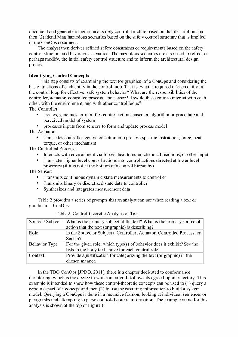
• Transmits continuous dynamic state measurements to controller • Transmits binary or discretized state data to controller • Synthesizes and integrates measurement data Table 2 provides a series of prompts that an analyst can use when reading a text or
graphic in a ConOps.
Table 2. Control-theoretic Analysis of Text
Source / Subject What is the primary subject of the text? What is the primary source of action that the text (or graphic) is describing?
Role Is the Source or Subject a Controller, Actuator, Controlled Process, or Sensor?
Behavior Type For the given role, which type(s) of behavior does it exhibit? See the lists in the body text above for each control role
Context Provide a justification for categorizing the text (or graphic) in the chosen manner.
In the TBO ConOps [JPDO, 2011], there is a chapter dedicated to conformance
monitoring, which is the degree to which an aircraft follows its agreed-upon trajectory. This example is intended to show how these control-theoretic concepts can be used to (1) query a certain aspect of a concept and then (2) to use the resulting information to build a system model. Querying a ConOps is done in a recursive fashion, looking at individual sentences or paragraphs and attempting to parse control-theoretic information. The example quote for this analysis is shown at the top of Figure 6.
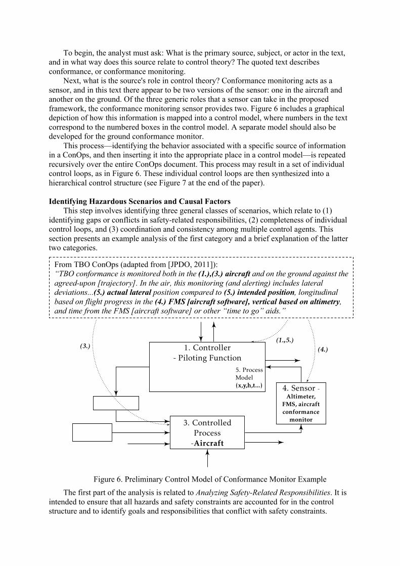
To begin, the analyst must ask: What is the primary source, subject, or actor in the text, and in what way does this source relate to control theory? The quoted text describes conformance, or conformance monitoring.
Next, what is the source's role in control theory? Conformance monitoring acts as a sensor, and in this text there appear to be two versions of the sensor: one in the aircraft and another on the ground. Of the three generic roles that a sensor can take in the proposed framework, the conformance monitoring sensor provides two. Figure 6 includes a graphical depiction of how this information is mapped into a control model, where numbers in the text correspond to the numbered boxes in the control model. A separate model should also be developed for the ground conformance monitor.
This process—identifying the behavior associated with a specific source of information in a ConOps, and then inserting it into the appropriate place in a control model—is repeated recursively over the entire ConOps document. This process may result in a set of individual control loops, as in Figure 6. These individual control loops are then synthesized into a hierarchical control structure (see Figure 7 at the end of the paper).
Identifying Hazardous Scenarios and Causal Factors
This step involves identifying three general classes of scenarios, which relate to (1) identifying gaps or conflicts in safety-related responsibilities, (2) completeness of individual control loops, and (3) coordination and consistency among multiple control agents. This section presents an example analysis of the first category and a brief explanation of the latter two categories.
Figure 6. Preliminary Control Model of Conformance Monitor Example
The first part of the analysis is related to Analyzing Safety-Related Responsibilities. It is intended to ensure that all hazards and safety constraints are accounted for in the control structure and to identify goals and responsibilities that conflict with safety constraints.
1. Controller- Piloting Function
7. 5. ProcessModel(x,y,h,t...)
2.
3. ControlledProcess-Aircraft
4. Sensor -Altimeter,
FMS, aircraftconformance
monitorAlt.
Controller
From TBO ConOps (adapted from [JPDO, 2011]):“conformance is monitored both in the (1.),(3.) aircraft and on theground against the agreed-upon [trajectory]. In the air, this monitoring(and alerting) includes lateral deviations...(5.) actual lateral positioncompared to (5.) intended position, longitudinal based on flight progressin the (4.) FMS [aircraft software], vertical based on altimetry, and timefrom the FMS [aircraft software] or other ‘time to go’ aids.”
(4.)
(1.,5.)
(3.)
Figure 1: Graphical Control Model of Airborne Conformance Monitor
1
From TBO ConOps (adapted from [JPDO, 2011]): “TBO conformance is monitored both in the (1.),(3.) aircraft and on the ground against the agreed-upon [trajectory]. In the air, this monitoring (and alerting) includes lateral deviations...(5.) actual lateral position compared to (5.) intended position, longitudinal based on flight progress in the (4.) FMS [aircraft software], vertical based on altimetry, and time from the FMS [aircraft software] or other “time to go” aids.”
Hazardous scenarios may occur if any of the safety constraints are unaccounted for, or if any goals in the system conflict with safety constraints.
For example, recall the loss of separation hazard defined above. In general, loss of separation occurs whenever the protected airspaces (e.g. a buffer of 5 miles laterally) of any two aircraft overlap. In safety-driven design, there must be at least one control entity that is responsible for assuring that this loss of separation hazard does not occur. The goal of air traffic controllers, then, is to generate clearances such that separation minima are always maintained.
One of the objectives prescribed in the TBO ConOps is to ensure that the aircraft conform to their assigned trajectories. In addition to assuring separation, in TBO the air traffic controllers have the additional goal of assuring conformance. TBO thus satisfies the first general rule for Analyzing Safety-Related Responsibilities. That is, safety responsibility is assigned to at least one control agent for the minimum separation hazard.
The next aspect of analyzing the safety responsibilities involves identifying potential conflicts among other system goals and assuring loss of separation. With respect to conformance monitoring and loss of separation, the system must ensure that the respective goals do not cause conflicts. Does the TBO ConOps guarantee that such a condition does not, or cannot exist? There is a conflict with safety responsibilities if there exists an action that can simultaneously result in the loss of separation hazard and fulfill the conformance condition. Such an action is possible if there are any aircraft (or any other debris or hazardous situation) in the presence of the intended aircraft trajectory or conformance volume. The following section describes this scenario, and associated causal factors, in more detail.
STECA should also identify scenarios related to completeness of the control loops, i.e. whether the controllers have proper goals, can act on the process under their control, and can ascertain changes in the process via feedback. Hazardous scenarios may arise whenever any of these conditions are not satisfied.
Finally, hazardous scenarios may involve (the lack of) coordination and consistency among multiple controllers. In many complex systems, more than one controller can affect a process, and these scenarios involve potentially inconsistent commands or lack of priority. In addition, multiple controllers may have a model of the same process, and hazardous scenarios arise when these models become inconsistent.
Derive Refined Safety Constraints
Hazard analyses or safety assessments should not be used to merely state whether the systems or components are “Safe” or “Unsafe”. The results should drive the design of the system. Once the scenarios have been identified, the key to safety-driven design is reasoning about (a) how to prevent the scenarios and (b) how to mitigate the scenarios if they occur. For example, the following safety constraints can be derived from the conflict of responsibilities described in the previous section.
Scenario-I. ANSP issues command that results in aircraft closing (or maintaining) a 4DT, but that 4DT has a conflict. A conflict in these responsibilities occurs when any 4D trajectory has a conflict (conflict could be with another aircraft that is conforming or is non-conforming).
SC-I.1. ANSP should not attempt to close the trajectories (i.e. attempt conformance) if a conflict between trajectories exists and updated trajectories cannot be generated within TBD seconds (or TBD NM of separation) Rationale: This scenario arises because the ANSP has been assigned the responsibility to assure that aircraft conform with 4D trajectories as well as to assure loss of separation.
SC-I.1.a. Loss of separation takes precedence over conformance in all TBO procedures, algorithms, and human interfaces Relevant Causal Factors: Inappropriate or conflicting Goal Condition. For a human operator these requirements could be levied with respect to how the information is displayed; for automation the requirement could be levied in the algorithm in terms of the relative “weight” given to conformance versus generating new clearances.
SC-I.1.a.i. Loss of separation information must be presented to air traffic controller and/or flight crew Rationale: feedback and information should support the primary goal of maintaining separation
SC-I.1.a.ii. Loss of separation alert should be displayed more prominently when conformance alert and loss of separation alert occur together. This scenario includes cases where one alert exists and then the other occurs. This requirement could be implemented in the form of aural, visual, or other format(s). Rationale: feedback and information should support the goal condition
SC-I.1…etc… This process results in a set of safety-related requirements and constraints on the system being developed.
Refine, Modify Control Architecture
The previous section describes the identification of constraints, based on a control structure derived directly from the ConOps. In addition to these constraints, STECA can also be used to modify the system control structure in order to eliminate hazardous scenarios.
Consider a different example from the TBO ConOps, which states that the air traffic controllers (ANSP in Figure 7 at the end of the paper) will negotiate aircraft trajectories directly with flight deck and also with the aircraft dispatchers or airlines (FOC in the figure). Arrows labeled K and L in the control structure denote negotiations. By focusing on coordination and consistency, it can be seen by inspection of Figure 7 that aircraft have the potential of receiving control commands from multiple control agents. These control commands come in the form of approved trajectories, either directly from the ANSP, or in some cases the FOC. While there could be requirements that ensure the negotiations between ANSP-FOC are consistent with ANSP-Aircraft negotiations, there may be a more effective and simple approach.
This problem is perhaps more easily solved with general, control structure modifications. One could implement a high-level requirement that the FOC stops negotiating with the ANSP for all active flights (e.g. within TBD minutes of departure). Such a requirement changes the control structure, where the FOC no longer has control authority over active flights and only exchanges relevant aircraft state information. An alternative requirement is that the FOC and aircraft never negotiate simultaneously. The result is a change from Figure 7 to Figure 8.
Comparison to Traditional Approach Recall what is necessary for stakeholders to develop a concept. Two significant artifacts
of systems engineering, particularly in the early phases, are requirements and the definition of a system architecture. In terms of safety, requirements and architectures should eliminate or mitigate against as complete a set of hazardous scenarios as possible.
Therefore, a successful safety-driven design approach should (1) identify as many valid hazardous scenarios as possible, (2) assist in the identification of requirements and
safety-related constraints, and (3) help stakeholders develop a system architecture that eliminates or mitigates hazards.
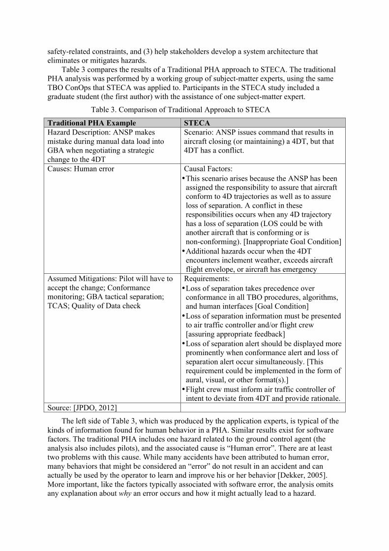
Table 3 compares the results of a Traditional PHA approach to STECA. The traditional PHA analysis was performed by a working group of subject-matter experts, using the same TBO ConOps that STECA was applied to. Participants in the STECA study included a graduate student (the first author) with the assistance of one subject-matter expert.
Table 3. Comparison of Traditional Approach to STECA
Traditional PHA Example STECA Hazard Description: ANSP makes mistake during manual data load into GBA when negotiating a strategic change to the 4DT
Scenario: ANSP issues command that results in aircraft closing (or maintaining) a 4DT, but that 4DT has a conflict.
Causes: Human error Causal Factors: • This scenario arises because the ANSP has been
assigned the responsibility to assure that aircraft conform to 4D trajectories as well as to assure loss of separation. A conflict in these responsibilities occurs when any 4D trajectory has a loss of separation (LOS could be with another aircraft that is conforming or is non-conforming). [Inappropriate Goal Condition] • Additional hazards occur when the 4DT
encounters inclement weather, exceeds aircraft flight envelope, or aircraft has emergency
Assumed Mitigations: Pilot will have to accept the change; Conformance monitoring; GBA tactical separation; TCAS; Quality of Data check
Requirements: • Loss of separation takes precedence over
conformance in all TBO procedures, algorithms, and human interfaces [Goal Condition] • Loss of separation information must be presented
to air traffic controller and/or flight crew [assuring appropriate feedback] • Loss of separation alert should be displayed more
prominently when conformance alert and loss of separation alert occur simultaneously. [This requirement could be implemented in the form of aural, visual, or other format(s).] • Flight crew must inform air traffic controller of
intent to deviate from 4DT and provide rationale. Source: [JPDO, 2012]
The left side of Table 3, which was produced by the application experts, is typical of the kinds of information found for human behavior in a PHA. Similar results exist for software factors. The traditional PHA includes one hazard related to the ground control agent (the analysis also includes pilots), and the associated cause is “Human error”. There are at least two problems with this cause. While many accidents have been attributed to human error, many behaviors that might be considered an “error” do not result in an accident and can actually be used by the operator to learn and improve his or her behavior [Dekker, 2005]. More important, like the factors typically associated with software error, the analysis omits any explanation about why an error occurs and how it might actually lead to a hazard.
Because of this lack of definition, the assumed mitigations are equally vague. PHA leaves out component interaction entirely.
The second column of Table 3—which presents sample STECA results—identifies hazardous human behavior that may arise due to conflicting goals, missing information, or confusion in the way that information is presented. STECA also leads to specific requirements that can be used to develop the human-computer interface (see the last row of the table). For example, the air traffic controller’s responsibility of separating aircraft should take precedence over other goals, which include assuring that aircraft remain on 4D trajectories. One way to enforce this constraint is to ensure that the information presented to controllers enforces their safety-related responsibilities.
Similarly, the traditional PHA on TBO identified causes as “software error” and suggested a mitigation of “extensive testing.” In contrast, STECA produced detailed functional software requirements to prevent the hazard.
Conclusions Comparisons between STECA and traditional PHAs on real systems show that STECA
identifies many more types of scenarios and factors than traditional PHA approaches. By using STECA during the concept formation stage, stakeholders and engineers can not only understand why hazardous behavior might occur but also derive constraints and requirements that will prevent the hazards. The systems- and control-theoretic framework also helps engineers to refine and modify the system control structure and to generate and compare potential system architectures that mitigate hazardous scenarios. Finally, STECA helps analysts, engineers, and other stakeholders identify and document more explicit and implicit assumptions about the system concept under development.
Acknowledgements This research was supported by NASA LEARN grant NNX14AC71A.
Acronyms ANSP Air Navigation Service Provider CAST Causal Analysis based on STAMP
ConOps Concept of Operations FOC Flight Operations Center PHA Preliminary Hazard Analysis PHL Preliminary Hazard List
STAMP Systems-theoretic Accident Model and Process STECA Systems-theoretic Early Concept Analysis
STPA Systems-theoretic Process Analysis TBO Trajectory-Based Operations (new paradigm for managing aircraft traffic)
References Ackoff, R.L. (1971). Towards a System of Systems Concepts. Management Science 17 (11):661-671. Ashby, W.R. (1957). An Introduction to Cybernetics, Chapman & Hall Ltd. Boehm, B., Kind, P., and Turner, R. (2002). Risky business seven myths about software engineering that impact
defense acquisition. Program Manager, 31(3): 74–80. Checkland, P. (1999). Systems Thinking, Systems Practice: includes a 30-year retrospective, John Wiley & Sons,
Inc. Crawley, E., de Weck, O., Eppinger, S., Magee, C., Moses, J., Seering, W., Schindall, J., Wallace, D., and
Whitney, D. (2004). The influence of architecture in engineering systems. In 1st Engineering Systems Symposium. MIT Engineering Systems Division, Cambridge, Massachusetts.
Dekker, S. (2005). Ten Questions About Human Error: A new view of human factors and system safety, CRC Press.
FAA (2008). Safety Management System Manual. Federal Aviation Administration Air Traffic Organization. FAA (2013). Nextgen Implementation Plan. Federal Aviation Administration, Washington, DC. Fleming, C.H. (2015). Safety-Driven Early Concept Analysis and Development, Ph.D. Thesis, Massachusetts
Institute of Technology. Frola, F. and Miller, C. (1984). System Safety in Aircraft Management. Logistics Management Institute,
Washington DC. Harkleroad, E., Vela, A., Kuchar, J., Barnett, B., Merchant-Bennett, R. (2013). ATC-045 Risk-based Modeling
to Support NextGen Concept Assessment and Validation. Technical report, MIT Lincoln Laboratory & Federal Aviation Administration.
INCOSE, (2011). INCOSE Systems Engineering Handbook v. 3.2. 2. Technical report, INCOSE-TP-2003-002-03.2. 2. October.
JPDO (2011). JPDO Trajectory-Based Operations (TBO) study team report. Technical report, Joint Planning and Development Office.
JPDO (2012). Capability safety assessment of trajectory based operations v1.1. Technical report, Joint Planning and Development Office Capability Safety Assessment Team.
Kapurch, S. J. (2010). NASA Systems Engineering Handbook. DIANE Publishing. Leveson, N. (2004a). “A new accident model for engineering safer systems”, Safety Science, 42(4): p. 237-270. Leveson, N.G. (2004b). “Role of software in spacecraft accidents”, Journal of Spacecraft and Rockets, 41(4): p.
564-575. Leveson, N.G. (2009). “Software Challenges in Achieving Space Safety”, Journal of the British Interplanetary
Society, 62, July/August. Leveson, N. (2012). Engineering a Safer World: Systems thinking applied to safety. Cambridge, MA, MIT
Press. Lutz, R. R. & Carmen Mikulski, I. (2003). “Operational anomalies as a cause of safety-critical requirements
evolution”, Journal of Systems and Software, Elsevier, 65, 155-161. McGregor, J. (2005). Arcade game maker pedagogical product line: Concept of operations. Version, 2:2005. Mesarovic, M.D.; Macko, D. and Takahara, Y. (1970). Theory of Multilevel Hierarchical Systems, New York,
Academic. Ramo, S. (1973). The Systems Approach, In Systems Concepts: Lectures on Contemporary Approaches to
Systems, ed. Ralph Miles, Jr. 13-32. New York, John Wiley & Sons. Rasmussen, J. (1997). “Risk management in a dynamic society: a modeling problem”, Safety Science, Elsevier,
27, 183-213 Reason, J. (1990). Human Error. Cambridge University Press. SAE (2010). ARP-4754A, Guidelines For Development Of Civil Aircraft and Systems. Strafaci, A. (2008). “What does BIM mean for civil engineers?” CE News, Transportation. US DoD. (2012). MIL-STD-882E, Department of Defense Standard Practice System Safety. U.S. Department of
Defense. Vesely, W. E.; Goldberg, F. F.; Roberts, N. H. and Haasl, D. F. (1981). Fault Tree Handbook DTIC Document. Vincoli, J. W. (2005). Basic Guide to System Safety, Second Edition. John Wiley & Sons, Inc., Hoboken, NJ,
USA. Woods, D. D.; Johannesen, L. J.; Cook, R. I. and Sarter, N. B. (2010). Behind Human Error Ashgate Publishing
Company.
Biography Cody Fleming obtained a doctoral degree in Aeronautics and Astronautics at the
Massachusetts Institute of Technology in January 2015. He holds a BS degree in Mechanical Engineering from Hope College and masters in Civil Engineering from MIT. Prior to returning to MIT, he spent 5 years working in space system development for various government projects.
Dr. Nancy Leveson is Professor of Aeronautics and Astronautics at MIT and a member of the National Academy of Engineering. She has authored over 200 published papers and two books, Safeware: System Safety and Computers (1995) and Engineering a Safer World (2012). She conducts research on all aspects of system safety and system engineering, including requirements, design, operations, management and social aspects of safety-critical systems.
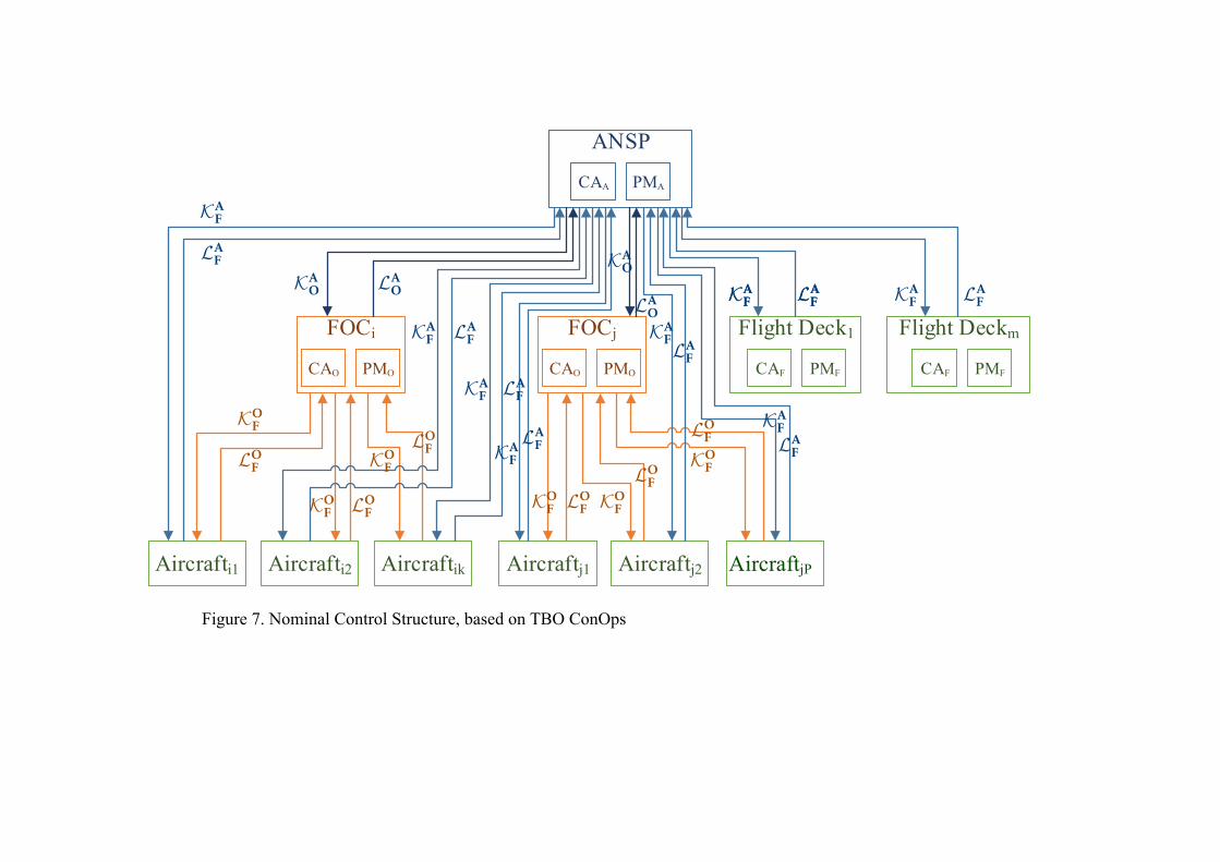
Figure 7. Nominal Control Structure, based on TBO ConOps
FOCi
Aircrafti1
ANSP
Aircrafti2 Aircraftik
FOCj
Aircraftj1 Aircraftj2 Aircraftjl
Flight Deck1 Flight Deckm
PMACAA
PMOCAO PMOCAO PMFCAF PMFCAF
KAO LA
O
KAO
LAO
KAF LA
F
KAF LA
F
KAF LA
F
KAF LA
F
KAF
LAF
KAFLA
F
KAFLAF
KAFLAF
KAF LA
F
KOF
LOF
KOF LO
F
KOF
LOF
KOF LO
F KOF
LOF
KOF
LOF
Figure 27: Nominal TBO Control Model—Trajectory Negotiation
150
AircraftjP
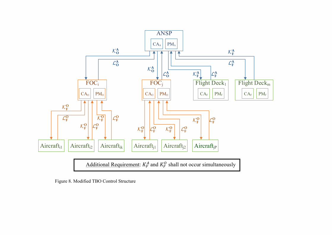
Figure 8. Modified TBO Control Structure
FOCi
Aircrafti1
ANSP
Aircrafti2 Aircraftik
FOCj
Aircraftj1 Aircraftj2 Aircraftjl
Flight Deck1 Flight Deckm
PMACAA
PMOCAO PMOCAO PMFCAF PMFCAF
KAO
LAO
KAO LA
O KAF LA
F
KAF
LAF
KOF
LOF
KOF LO
F
KOF LO
F
KOF LO
F KOF LO
F
KOF LO
F
◆✓
⇣⌘Additional Requirement: KA
F and KOF shall not occur simultaneously.
Figure 28: Modified TBO Control Model—Trajectory Negotiation
149
Additional Requirement: !!! and !!! shall not occur simultaneously
AircraftjP