integrating walking and vision to increase ... -...
TRANSCRIPT

January 15, 2008 18:14 WSPC/INSTRUCTION FILE ws-ijhr
International Journal of Humanoid Roboticsc© World Scientific Publishing Company
Integrating Walking and Vision
to increase Humanoid Autonomy
Olivier Stasse1, Bjorn Verrelst2, Andrew Davison3, Nicolas Mansard 4,
Francois Saidi1, Bram Vanderborght2, Claudia Esteves5, Kazuhito Yokoi1
1 JRL, AIST-CNRS, ISRI, Tsukuba, Japan
E-Mail : olivier.stasse,francois.saidi, [email protected] Vrije Universiteit Brussel, Belgium E-Mail : bjorn.verrelst,
[email protected] Imperial College of London, United Kingdom E-Mail : [email protected]
4 IRISA - INRIA Rennes, France E-Mail : [email protected] JRL, CNRS-AIST, LAAS, Toulouse, France E-Mail : [email protected]
Received 25/06/2007Revised 15/01/2008
Aiming at building versatile humanoid systems, we present in this paper the real-timeimplementation of behaviors which integrate walking and vision to achieve general func-tionalities. This paper describes how real-time -or high bandwidth- cognitive processes
can be obtained by combining vision with walking. The central point of our methodologyis to use appropriate models to reduce the complexity of the search space. We will de-scribe the models introduced in the different blocks of the system and their relationships:
walking pattern, Self Localization and Map Building, real-time reactive vision behaviors,and planning.
Keywords: appropriate models, integration, ZMP preview control, SLAM, planning, vi-sual servoing.
1. Introduction
A major challenge with versatile multi-purpose platforms such as humanoids is
to be able to cope efficiently and autonomously with a large range of applications.
This requires for a set of core functionalities to work in near real-time performances,
making few assumptions on the surrounding environment. This paper demonstrates
our current status in developing such a system for humanoid robots. Increasing
autonomy for humanoids implies cognitive capabilities. However, a common problem
with such complex robotic platforms is the inherent complexity of the detailed
models which represent the robot itself. We will show that appropriate simplified
models, as depicted in figure 1, make it possible to grasp the essence of problems,
while being suited for achieving efficient performances in real situations. The second
key point of this paper is to describe a general integration of motion and vision with
core functionalities: low-level vision functionalities, SLAM, vision-based planning
and a general motion generation framework allowing reactive behaviors.
1

January 15, 2008 18:14 WSPC/INSTRUCTION FILE ws-ijhr
2 O. Stasse, B. Verrelst, A. Davison, N. Mansard, F. Saidi, B. Vanderborght, C. Esteves, K. Yokoi
τ x
Y
Z
M
X
τ y
y x
z
Walking Pattern Generator
Planning
Self Localization
Map building
and
Fig. 1. HRP-2 using appropriate simplified models to speed-up its cognitive processes.
1.1. State of the art
There already exists a number of architectures which integrate vision and walking
for humanoid robots with impressive capabilities. Namely, Inoue, Inaba, Kagami,
Kuffner and Nishiwaki21 developed such a system on top of the humanoid robot
H7. This system is one of the most complete and advanced up to date. The walking
trajectories are built using a simplification of the ZMP: the bodies of the upper
torso are assumed to be moving together along the same planar motion. To the
authors’ knowledge this work has fostered one of the first real-time pattern gener-
ator ever proposed for a full body humanoid robot. Our system is also based on
a simplification, but it has less restrictions. It was proposed by Kajita 11. Inoue’s
team also proposed a full body motion planning method based on vision. In this
method the visual information is provided by a stereoscopic system 9, in a similar
way as we do. Kuffner 13 proposed to plan a motion using RRT and a dynamic
filter. The approach used is to first find a statically stable trajectory and then to
turn it into a dynamically stable one. Again in this paper a similar approach is
used, but which does not go through a statically stable trajectory phase. We use
3 different approaches according to the situation: a dynamical planner for stepping
over, a roadmap based approach for complex motion with a real-time dynamic fil-
ter, and a A* planner for visual search. Another difference with Nishiwaki et al. is
the fact that we also do planning in the 3D map, while they perform planning in a
2.5 D projection of their 3D map. The work of Okada deserves very much interest

January 15, 2008 18:14 WSPC/INSTRUCTION FILE ws-ijhr
Integrating Walking and Vision to increase Humanoid Autonomy 3
especially for a complete integration23 which would aim at a real application, i.e.
having HRP-2 acting as a kitchen maid22. His work is also one of the first to con-
sider the problem of planning manipulation tasks 6 in the context of such complex
real applications. For their primitive task executions they do use a task formulation
approach, but not explicitly formulated as a stack of tasks, as it is proposed in the
present paper which does offer a broader genericity. We however do not propose a
system managing high-level tasks as it is done in Okada’s system. One of the first
experiments where the robot changes its foot steps to step-over dynamically an
obstacle has been proposed by Lorch 16, based on a similar approach proposed by
Kuffner 13. They however limited the problem to a small obstacle of 5 cm. Recent
work by Bolder et al. 2 demonstrates ASIMO walking and generating reactivly full
body motion towards objects tracked visually. Their work is in the same spirit to
what is proposed in section 7, but our theoritical framework allow multiple priority
levels and insure smooth velocity transition between tasks.
This state of the art has been voluntarily limited to the work carried on real
humanoid platform with similar architecture. There are other works about the re-
lation between vision and humanoid motion generation 1 31 5. They often include
broader problems such as learning but none include walking considerations.
1.2. Interplay between vision and walking
We first applied our approach to dynamically step over large obstacles. Indeed in
order to find a suitable trajectory, we use a simplified dynamic model of the robot.
The stepping over is said to be dynamic in the sense because it is performed when
the robot is dynamically stable. The key point to perform such motion is to lower
the height of the waist, which violates one of the assumptions the pattern generator
has been built upon. This can be done thanks to the particular robustness of the
compensation scheme proposed by Kajita. This can be exploited further to plan
complex motion with a semi-simplified model of a real HRP-2 humanoid robot. By
using a 3D reconstruction of the humanoid coupled with a planner, it is possible
to make the humanoid robot handle a 2 m meter bar and go through a door too
small for his size. In the following section, we illustrate how monocular SLAM can
be enhanced by introducing the information provided by the pattern generator.
This allow to get rid of a limitation of the initial algorithm, namely initial known
landmarks. The fourth part shows that by using a prioritized stack of tasks, it is
possible to realize a visually-based grasping while walking. The pattern generator is
here coherently integrated as a task. The fifth section describes our current status
regarding visual search of a known object in an unknown environment. Finally the
conclusion follows the description of our overall software architecture.
2. Software integration
The overall software structure of the system is depicted in figure 2. It consists of
five CORBA servers following a functional decomposition. The different perception-

January 15, 2008 18:14 WSPC/INSTRUCTION FILE ws-ijhr
4 O. Stasse, B. Verrelst, A. Davison, N. Mansard, F. Saidi, B. Vanderborght, C. Esteves, K. Yokoi
Real−timeLoop
Motion
feedback
Sensors
Actuators
CORBA
decision loop
High level
Visual Attention Server
VAS
LLVS
Low Level Vision Server
WMS
World Model Server
MGS
Motion Generator Server
PPS
Path Planner Server
Probability World
Map Process
Next Best View
Process
Disparity
Color detection
SLAM
Voxel grid
Walking Pattern
Generator
Stack of Tasks
Step Over
A* Kineoworks
Fig. 2. Overall software structure and the multiple perception-action loops.
action loops described below are schematically represented by dashed lines.
Low Level Vision Server: This server is in charge of acquiring the image
and of synchronizing multiple cameras. Besides, it provides other servers with the
camera models, and also a graph of low level image processes. This graph includes:
image rectification, filtering, disparity computation, edge detection, color detection
and so on. For those purposes we integrated several vision libraries 29 7 4. This is
also where we integrated the SLAM system presented in section 6, thus avoiding
any overhead through the middleware.
World Model Server: This server handles and computes the internal world
representation. In this particular context, it receives an estimation of the vision
system position and an associated range map. The position is given either by the
SLAM process or by odometry, but other means can also be used. The environment
representation is then updated by comparing the voxels in the field of view with
those of a range map 27.
January 15, 2008 18:14 WSPC/INSTRUCTION FILE ws-ijhr
Integrating Walking and Vision to increase Humanoid Autonomy 5
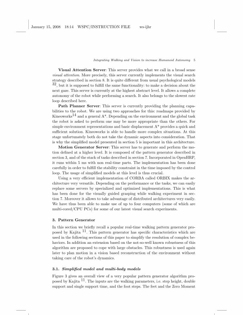
Visual Attention Server: This server provides what we call in a broad sense
visual attention. More precisely, this server currently implements the visual search
strategy described in section 8. It is quite different from usual psychological models32, but it is supposed to fulfill the same functionality: to make a decision about the
next gaze. This server is currently at the highest abstract level. It allows a complete
autonomy of the robot while performing a search. It also belongs to the slowest rate
loop described here.
Path Planner Server: This server is currently providing the planning capa-
bilities to the robot. We are using two approaches for this: roadmaps provided by
Kineoworks14 and a general A*. Depending on the environment and the global task
the robot is asked to perform one may be more appropriate than the others. For
simple environment representations and basic displacement A* provides a quick and
sufficient solution. Kineoworks is able to handle more complex situations. At this
stage unfortunately both do not take the dynamic aspects into consideration. That
is why the simplified model presented in section 5 is important in this architecture.
Motion Generator Server: This server has to generate and perform the mo-
tion defined at a higher level. It is composed of the pattern generator described in
section 3, and of the stack of tasks described in section 7. Incorporated in OpenHRP,
it runs within 5 ms with non real-time parts. The implementation has been done
carefully in order to fulfill the stability constraint in the time imposed by the control
loop. The usage of simplified models at this level is thus crucial.
Using a very efficient implementation of CORBA called ORBIX makes the ar-
chitecture very versatile. Depending on the performance or the tasks, we can easily
replace some servers by specialized and optimized implementations. This is what
has been done for the visually guided grasping while walking experiment in sec-
tion 7. Moreover it allows to take advantage of distributed architectures very easily.
We have thus been able to make use of up to four computers (some of which are
multi-cored/CPU PCs) for some of our latest visual search experiments.
3. Pattern Generator
In this section we briefly recall a popular real-time walking pattern generator pro-
posed by Kajita 11. This pattern generator has specific characteristics which are
used in the following sections of this paper to simplify the resolution of complex be-
haviors. In addition an extension based on the not-so-well known robustness of this
algorithm are proposed to cope with large obstacles. This robustness is used again
later to plan motion in a vision based reconstruction of the environment without
taking care of the robot’s dynamics.
3.1. Simplified model and multi-body models
Figure 3 gives an overall view of a very popular pattern generator algorithm pro-
posed by Kajita 11. The inputs are the walking parameters, i.e. step height, double
support and single support time, and the foot steps. The feet and the Zero Moment

January 15, 2008 18:14 WSPC/INSTRUCTION FILE ws-ijhr
6 O. Stasse, B. Verrelst, A. Davison, N. Mansard, F. Saidi, B. Vanderborght, C. Esteves, K. Yokoi
Upper body
motion
and CoM’s height
modification Dynamic filtering
Fig. 3. ZMP Preview Control scheme
Point (ZMP) reference trajectories stem from this information. In common know-
ledge, the ZMP reference trajectory is used to generate the first set of Center of
Mass (CoM) trajectories. Kajita’s scheme consists in using an optimization problem
considering a preview window to solve an inverse problem. One key idea to do so is
to use a simplified model of the robot’s dynamic.
Once this trajectory is generated, there are two possibilities: either make the
robot behave like the simplified model, or find a way to modify the CoM trajectory
to take into account the robot’s specificities. Kajita proposed a solution for both
possibilities, but this paper focuses on the second one. Thus, the knowledge of CoM
trajectory, feet position and an upper body motion allow, via inverse kinematics,
to compute a robot attitude. This attitude is then used to compute the ZMP of the
robot’s multi-body model. The difference between the newly computed multi-body
ZMP and the ZMP reference is injected into a second preview control loop. This
second preview loop offers a correction of the CoM to make sure that the generated
ZMP is close to the reference.
3.2. CoM trajectory generation
Different approaches also exist to generate the CoM trajectory, but we describe the
one proposed by Kajita 11, The latter takes into account the future by means of
a preview window. Moreover, a second stage takes into account the full multibody
model of the robot and still hold its real-time capabilities. This concept is very
important as it allowed us to create two novel behaviors. Often it is not properly
taken into account, because classically the robot is forced to behave as an inverted

January 15, 2008 18:14 WSPC/INSTRUCTION FILE ws-ijhr
Integrating Walking and Vision to increase Humanoid Autonomy 7
pendulum. The approach is quickly recalled as it is used later in this paper to
decrease the complexity of planning in a environment reconstructed by 3D vision,
to help a Self Localization Map Building process, and is used as an important
constraint to reduce the search space in a visual search behavior.
Assuming the future steps are known, it is possible to deduce a set
p0, ..., pNL−1 of future ZMP positions. The main issue is to solve the inverse prob-
lem which finds a CoM trajectory from the desired ZMP trajectory. For a given axis,
say x, this can be achieved by solving the following optimization problem:
min...x (k),··· ,
...x (k+NL)
k+NL−1∑
i=k
1
2Q(px(i + 1) − pref
x (i + 1))2 +1
2R
...x 2(i) (1)
where the first term represents the difference between the actual ZMP and the
desired one, and the second term is the jerk of the CoM. Q and R are weights
which influence the importance of each term in the cost function. Using an iterative
scheme, and assuming that both CoM and ZMP trajectories are discretized by
piecewise cubic polynomials over time intervals of constant length T , the following
recursive relationship is obtained:
x(k + 1) = Ax(k) + B...x (k),
p(k) = Cx(k),(2)
where
x(k) ≡ [x(k) x(k) x(k)]T ,
A ≡
1 T T 2/2
0 1 T
0 0 1
,B ≡
T 3/6
T 2/2
T
,C ≡
[
1 0 −zc
g
]
(3)
Finally the optimal controller which minimizes the performance index, formulated
by equation (1), is given by:
...x (k) = −G1
k∑
i=0
e(i) − G2x(k) −
NL∑
j=1
Gp(j)pref (k + j) (4)
where e(i) = px(i) − prefx (i), and G1, G2 and Gp(j) are the gains calculated from
the weights Q and R and the parameters used in the system described by equation
(2). It is interesting to note the unicity of the weights Gp(j) for a given control
period T , preview window NL and constant CoM height zc. This latter extension is
important because it enables the robot to take the following step into account. The
importance of this future is given by the solution of the weights Gp(j). However if
there is a sudden change due to modifications of the environment, the trajectory
needs to be recomputed. This new trajectory should handle the current state of the
robot, and the next step. Nishiwaki 20 proposed an extension of Kajita’s 11 control
scheme to deal with such situation.

January 15, 2008 18:14 WSPC/INSTRUCTION FILE ws-ijhr
8 O. Stasse, B. Verrelst, A. Davison, N. Mansard, F. Saidi, B. Vanderborght, C. Esteves, K. Yokoi
Fig. 4. (left) Example of full body motion lowering the height of the waist. (right) Compensation
between the 3D LIPM model and the multi-body model.
3.3. Realizing the CoM trajectory
In section 3.2 we explained that the CoM trajectory provided by the algorithm is
based upon a simplified model of the robot. From this trajectory we can adopt
several strategies to compute the corresponding joint values. We can either make
the robot act as an inverse pendulum by controlling the CoM and momenta through
the Resolved Momentum Control as realized by Neo 19, or by the CoM jacobian 28.
Our current strategy is the one suggested by Kajita 11. It assumes that the waist is
rigidly fixed to the CoM. In the case of robots with 6 DOF legs, such as HRP-2, it
is possible to solve the problem using inverse kinematics. A second preview-loop is
computed to compensate for the discrepancy between the ZMP reference trajectory
and the ZMP trajectory computed from the previous solution considering the multi-
body model. This second preview-loop acts as a dynamic filter, and offers a way
to modify the CoM trajectory. In his book, Kajita10 also shows the robustness of
this particular stage by lowering the waist about 0.11 m and strongly bending the
chest. A slightly different example is given in figure 4 (right), where the robot is
simply lowering the waist. They are already disturbances up to 2 ∼ 3 cm without
correction. The graphs show the ZMP multi-body computed after the first preview
control stage, and after the second preview control. In this case the waist was
lowered down of 15 cm. However, to the extent of the authors’ knowledge, there
is no example of applications using this robustness. In this paper we present two
applications: stepping over and planning with a simplified model. The latter is fully
explained for the first time. Those two applications rely on the possibility to lower
the waist.
3.4. Lowering the CoM
As it has been shown previously, the main simplification of the robot’s dynamic is
realized by constraining the evolution of the height’s CoM on a horizontal plane.

January 15, 2008 18:14 WSPC/INSTRUCTION FILE ws-ijhr
Integrating Walking and Vision to increase Humanoid Autonomy 9
Lowering the CoM is a direct violation of the assumption. In the other hand, the
second Preview-Control compensates to some extend the perturbations of the sim-
plified model trajectory. There are other works allowing to lower the waist: Kagami
with the AutoBalancer allows to specify arbitrary modification of heights for each
body. The constraint is however to have a common motion for all bodies in the
horizontal plane. This constraint is much harder than the one proposed by Kajita
limited to the CoM. More recently Harada8 under the same assumption introduced
by Kajita, and assuming than the ZMP has a polynomial form shows that it is
possible to compensate for the vertical motion of the 3D Linear Inverted Pendulum
Model (3DLIPM). There is no compensation scheme for the discrepencies between
the multibody model and the inverted pendulum. This is mainly due to the fact
that Harada uses a Resolved Momentum Control scheme to force the robot to act
as an inverted pendulum. In section 5, we use the CoM as a degree of freedom which
can be modify to realize arbitrary motion of the upper torso.
A different approach has been proposed recently by Terada 30. Instead of con-
straining the evolution of the CoM’s height to a plan, it is constraining the shape of
the CoM’s height acceleration. It then obtains a Bessel differential equation which
is solved using Bessel functions. The associated coefficient can be computed in real
time 30. Using Kajita’s dynamic filter we do not need to comply with such con-
straint.
4. CoM’s Height modification for stepping over large obstacles
Verrelst et al.33 used the simplified dynamic model of the robot and the first stage of
the pattern generator explained previously as a dynamic planner. Once the obstacle
position and size are given, the dynamic planner is used with a simplified collision
checker customized for HRP-2 to find the appropriate height to go over the obstacle
without collision. This technique allowed us to successfully clear dynamically large
obstacles: 10 cm by 5 cm, 15 cm by 5 cm, 10 cm by 10 cm (obstacle’s width and
height respectively) each surrounded by a 3 cm safety boundary.
The main limitation of the approach 33 is due to the stabilizer commercially
available on the robot. Indeed for high obstacles, the swing leg is close to a stretch
position. The current stabilizer is sending high accelerations near this position of
the swing leg, and those accelerations are not allowed by the low-level security
mechanisms embedded inside the robot.
5. CoM’s Height modification with 3D reconstruction and
planning
This section is presenting our preliminary experiment using the new degree of free-
dom corresponding to possible variation of the CoM’s height. The robot is facing
an opening 2 meters far away with an other wall (beyond the door) at 4 meters
(cf figure 5(up-left)). The goal is to cross the door while manipulating a 2 m long

January 15, 2008 18:14 WSPC/INSTRUCTION FILE ws-ijhr
10 O. Stasse, B. Verrelst, A. Davison, N. Mansard, F. Saidi, B. Vanderborght, C. Esteves, K. Yokoi
Fig. 5. (top) HRP-2 going down to clear a door while manipulating a 2m bar to avoid the wallin front of the door. (bottom) Environment reconstruction inside KineoWorks with a simplifiedmodel
bar hold in the right hand. The environment was reconstructed by using the em-
bedded stereoscopic vision system using previous work 27. In short, several dense
maps were accumulated to give the map depicted in figure 5 (bottom). The result
has been then processed to simplify the geometry of the raw vision output. It is
then used as an entry to KineoWorks a general 3D motion planner 14. Kineoworks
searched and optimized the configuration space of a HRP-2 reduced model depicted
in the left of figure 5 (bottom). In the reduced model the legs are regarded as a
bounding box with four degrees of freedom: three in the horizontal plane, and one
small translation at the top of the box for the height modification. The upper torso
is kept complete i.e. all its dofs are considered in the planning problem. Standard
Rapidly-Exploring Random Trees 15 or Probabilistic Roadmaps 12 algoritms can
be used at this point to plan the motions of this simplified model.
The output is a set of points (x, y, ztr, θ,qtorso) also called key-points. Between
each key-points it is possible to linearly interpolate the position, the orientation
and the angular values of the upper torso to realize a motion without collision from

January 15, 2008 18:14 WSPC/INSTRUCTION FILE ws-ijhr
Integrating Walking and Vision to increase Humanoid Autonomy 11
Fig. 6. Visualization of the “constant velocity” model for smooth motion
a pure geometric viewpoint. The articular values qtorso are used as direct input
of the pattern generator, whereas x, y, θ are used to generate steps. Indeed the
upper body motion influences the ZMP, consequently the CoM trajectory has to
be adapted accordingly. The bounding box corresponding to the legs, insure that
those steps can be realized. More precisely, from the steps the pattern generator
provides a CoM trajectory. As the waist is supposed to be here rigidly fixed, a
waist trajectory is associated but it is different from the solution by Kineoworks.
However it is guaranteed to be included into the bounding box moving along the
found trajectory. In order to synchronize at best the key-points on the real trajectory
of the robot, the key-points are remapped on the closest points along the waist (root
of the robot model) trajectory. In the present experiment, the optimization was not
done taken into consideration the dynamics of the robot-bar system. It was assumed
that the pattern generator is able to compensate for the variation introduced by
the upper body. Of course, this hypothesis is not valid for any motion and any
robot-object dynamic system. The successful experiment here was achieved with a
100 g bar, whereas a 1 kg bar append to induce too much momentum and make
the robot fall. However the range of acceptance of the system is wide, and when
this hypothesis is valid it provides a faster solution. It should be noted that as this
work is in its early stage, the planning phase has been done off-line. The result is a
set of configurations for the upper body according to the position of the waist. The
corresponding file is then loaded inside the pattern generator, and the trajectory of
the foot and the waist are generated on-line as in the previous experience.
6. SLAM together with Pattern Generator Information
In this section, we present a visual real-time Self Localization and Map building algo-
rithm taking into account the motion computed by the pattern generator presented
previously. Taking into account this information has two important consequences:
it allows to run in real-time the algorithm inside the robot which is not possible
using vision only, and allows to get rid of the initial landmarks.
6.1. The simplified model
Self Localization And Map-building is a cornerstone to achieve autonomous be-
havior. The key point of our system is to make the robot able to self-localize in

January 15, 2008 18:14 WSPC/INSTRUCTION FILE ws-ijhr
12 O. Stasse, B. Verrelst, A. Davison, N. Mansard, F. Saidi, B. Vanderborght, C. Esteves, K. Yokoi
real-time in a new environment equivalent to a room without any a-priori know-
ledge. Another key point of the presented system is its capability to “close the loop”,
i.e. to increase the precision by seeing again the same landmarks when returning to
a previous location. This is a key difference with previous humanoid systems. The
core work related to SLAM used in this paper has been proposed by Davison 3. We
recall briefly the model used to evaluate the motion model and used for prediction.
First the estimated state and covariance of the system are given by:
x =
xv
y1
y2
...
, P =
Pxx Pxy1Pxy2
. . .
Py1x Py1y1Py1y2
. . .
Py2x Py2y1Py2y2
. . ....
......
. (5)
Explicitly, the camera’s state vector xv comprises a metric 3D position vector rW ,
orientation quaternion qWR, velocity vector vW and angular velocity vector ωR
(a total of 13 parameters). Feature states yi are 3D position vectors. In the Ex-
tended Kalman Filter (EKF) prediction step a model for smooth motion anticipates
Gaussian-distributed perturbations VW and ΩR to the camera’s linear and angular
velocity at each time-step — modeling motion with a generally smooth character.
The explicit process model for motion in a time-step ∆t is:
fv =
rWnew
qWRnew
vWnew
ωRnew
=
rW + (vW + VW )∆t
qWR × q((ωR + ΩR)∆t)
vW + VW
ωR + ΩR
(6)
Figure 6 illustrates the models potential deviations from a constant velocity tra-
jectory. Implementation requires calculation of the Jacobians of this function with
respect to both xv and the perturbation vector.
6.2. Taking walking information into account
Supplying an EKF based SLAM system with robot’s motion model is not new, but
specificity of the humanoid robot makes it interesting. Indeed the oscillation of the
CoM in the horizontal plane creates a parallax effect which helps new landmarks
initialization. Moreover - and this is one of this paper’s innovative contributions -
initial landmarks no longer remain necessary. The latters were indeed required in
the system 3 for an initial state estimation, but they can be removed if the election
of the new landmarks is triggered only when the robot moves. The idea is to pin-
point 3D features only when the robot is in motion. In 25 we described precisely
the experimental context and the current limitation of the system (number of land-
marks, size of the environment). One could object that the on-board stereoscopic
system could perfectly be used to initialize landmarks, and hence solve the problem.
This is true, but from a global application viewpoint, SLAM rather a functionality
than a goal. The fact that the robot can perform SLAM without actively moving

January 15, 2008 18:14 WSPC/INSTRUCTION FILE ws-ijhr
Integrating Walking and Vision to increase Humanoid Autonomy 13
Fig. 7. Trajectory generated by coupling vision and the motion information. (left) Landmarks(right) Trajectories and sparse map.
its head gives more freedom and allows simultaneous performances of several tasks.
Moreover, if a drift accumulates for too long, the search for landmarks can take
long enough for image frames to be skipped, and the uncertainty grows. This effect
January 15, 2008 18:14 WSPC/INSTRUCTION FILE ws-ijhr
14 O. Stasse, B. Verrelst, A. Davison, N. Mansard, F. Saidi, B. Vanderborght, C. Esteves, K. Yokoi
Centering
Gripper Height
Joint avoidance
Task controllers
Neck joint limit
Gripper Orientation (Z)
Chest tilt
Grasping
Distance to object
Stack of Tasks
Walking
CoM
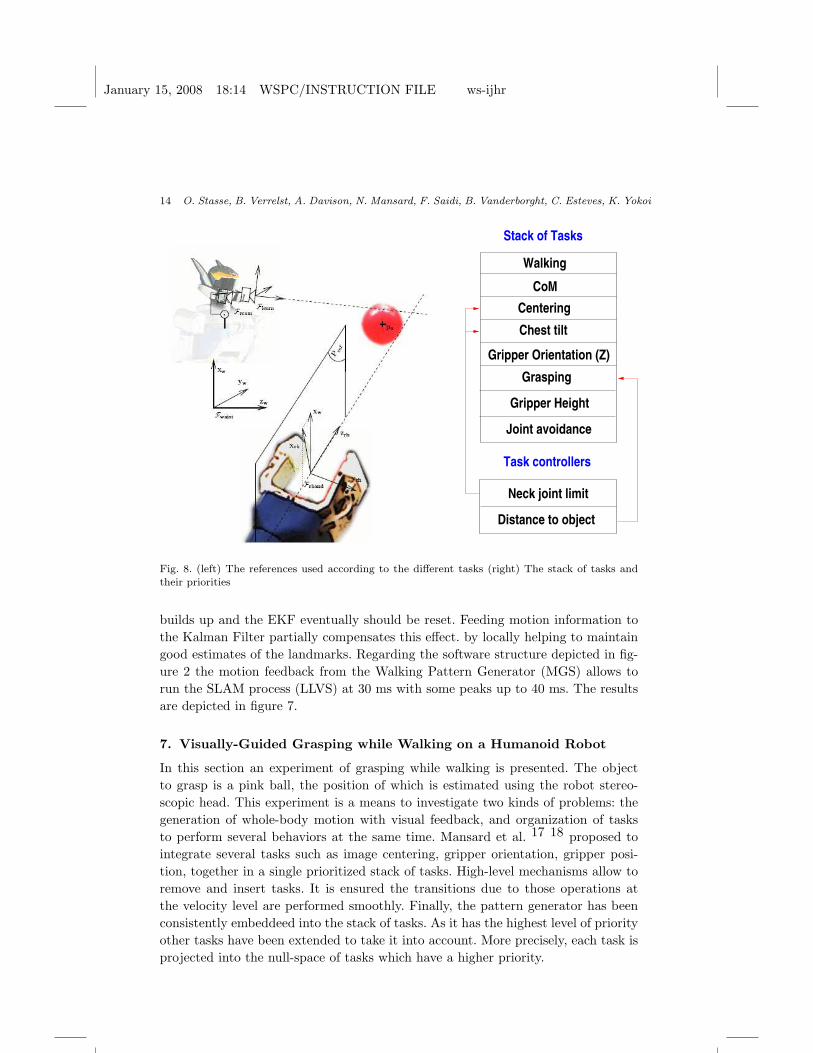
Fig. 8. (left) The references used according to the different tasks (right) The stack of tasks andtheir priorities
builds up and the EKF eventually should be reset. Feeding motion information to
the Kalman Filter partially compensates this effect. by locally helping to maintain
good estimates of the landmarks. Regarding the software structure depicted in fig-
ure 2 the motion feedback from the Walking Pattern Generator (MGS) allows to
run the SLAM process (LLVS) at 30 ms with some peaks up to 40 ms. The results
are depicted in figure 7.
7. Visually-Guided Grasping while Walking on a Humanoid Robot
In this section an experiment of grasping while walking is presented. The object
to grasp is a pink ball, the position of which is estimated using the robot stereo-
scopic head. This experiment is a means to investigate two kinds of problems: the
generation of whole-body motion with visual feedback, and organization of tasks
to perform several behaviors at the same time. Mansard et al. 17 18 proposed to
integrate several tasks such as image centering, gripper orientation, gripper posi-
tion, together in a single prioritized stack of tasks. High-level mechanisms allow to
remove and insert tasks. It is ensured the transitions due to those operations at
the velocity level are performed smoothly. Finally, the pattern generator has been
consistently embeddeed into the stack of tasks. As it has the highest level of priority
other tasks have been extended to take it into account. More precisely, each task is
projected into the null-space of tasks which have a higher priority.

January 15, 2008 18:14 WSPC/INSTRUCTION FILE ws-ijhr
Integrating Walking and Vision to increase Humanoid Autonomy 15
The task which has the highest level of priority is walking. Because preview
control needs to know the future, the visual-servoing command cannot take part in
the pattern generator. However, as explained in section 3, the latter provides a refer-
ence trajectory for the CoM. Therefore just after the walking task, we implemented
Fig. 9. HRP-2 grasping a moving ball (up) view from the outside (bottom) view from the camera
a task named CoM, whose role is to make sure that the current CoM follows the
reference one. CoM can perform this check by computing the Jacobian of the CoM28. This means that the robot is constrained to act as a Linear Inverted Pendulum.
All the other tasks are projected into the null-space of the walk and CoM tasks, and
thus cannot disturb the stability of the robot. Another approach has been proposed
by Neo et al. 19: it consists in generating in real-time stable whole-body motion for
a HRP-2 robot taking momenta into account as well. However this method did not
integrate a prioritization of tasks.
In this experiment two high-level controllers check the neck joints limits and the
distances to objects. The first controller starts tilting of the chest if the neck joint
limits are reached. The second controller starts the grasping of the ball, provided
the gripper is close enough. It also monitors the gripper torque to make sure that
the robot did not miss the ball, otherwise it switches back in trying to grasp the
ball. The overall stack of tasks is depicted in figure 8.
This experiment is the fastest loop in the architecture depicted in figure 2. We
use a color-detection with 3D reconstruction (LLVS) to evaluate the 3D position of
a pink ball. This takes 8 ms and is achieved at 30 Hz. The information is send to
the control part which runs at 200 Hz. To predict the next position of the ball, a
Kalman filter is used. The overall delay between perception and action is 140 ms.
The control part which is quite time consuming due to numerous pseudo-inverse
computations is performed in 2 ms. The experiment is depicted in figure 9.
We intend to use the framework developed in this work as a basis for further
complex behaviors. The reader is kindly invited to read the work of Mansard et al.

January 15, 2008 18:14 WSPC/INSTRUCTION FILE ws-ijhr
16 O. Stasse, B. Verrelst, A. Davison, N. Mansard, F. Saidi, B. Vanderborght, C. Esteves, K. Yokoi
17 for further details.
8. Visual Search
In this section we present a high-level behavior which relies on all the previously
presented functionnalities to reason and take autonomously a decision in order to
find an object. Our main contribution is to introduce the constraints related to the
walking algorithm and the recognition system into one entity called the visibility
map to reduce the space of the sensor configuration.
8.1. Introduction
Sensor planning to find a known object in an unknown environment using vision
with a mobile platform is an old problem which received a lot of attention during
the 80s. Most of this work relied on the use of a range finder coupled with a camera,
whereas the object model was either a polyhedron, a 3-edge based representation
or a voxel grid description. Even so the recognition process is still valid, and used
in recent humanoid applications by Neo 19 to achieve autonomous behavior, it is
interesting to revisit this problem in the context of humanoids. Indeed new available
hardware such as multi-core CPUs make efficient implementation of such algorithms
possible. However as this problem is NP-complete, simplified models are still nec-
essary to simplify the search. Finally, the motion capabilities of humanoid robots,
instead of the classical 2D representation of the search space, requires the adoption
of a 3D representation.
8.2. The simplified model
In this work we consider mainly the problem of finding the best next camera pose
to search an object in an unknown environment. Here the camera pose is given by
a 3D position plus an orientation provided by pan and tilt values, which give us a
five dimensional space. In order to simplify the problem we 24 take into account
two considerations: the robot’s motion capabilities, the recognition system’s char-
acteristics. Depending on the task different recognitions can be used, as we have at
our disposal either a 3D-edge model 29 or a Spin-Image 26.
The first consideration allows to limit the domain of the pan and tilt values
according to the joint limits. Moreover if we consider only the case where the robot
walks24, the vertical axis can be deduced from the constraint on the CoM. The
second consideration implies to use a model of the recognition system. But in addi-
tion to the classical statistical model, we consider that they are practical bounding
values (Rmin, Rmax) for which the recognition system is able to work. From this ad-
ditional information found experimentally and which vary according to the object
we proposed the concept of visibility map.

January 15, 2008 18:14 WSPC/INSTRUCTION FILE ws-ijhr
Integrating Walking and Vision to increase Humanoid Autonomy 17
Fig. 10. Visibility sphere for a given 3D point.
8.3. The visibility map
In order to explain what visibility map is, we shall introduce the concept of visibility
sphere. Let us assume that we have a partial representation of the world using a
voxel grid representation. A visibility sphere is the set of poses for which an unknown
or solid point of the voxel grid is seen within the perception interval (Rmin, Rmax).
A visibility map can then be defined by the intersection between the constraints
related to the robot’s motions and the visibility spheres centered on each voxel of
the world map, as depicted in figure 10. When the robot walks, the height of the
camera is fixed, so the visibility map is a plane going through the head of the robot.
This plane is depicted in figure 11 (top). On the left of the figure is depicted a scene
along with its 3D reconstruction over 5 views. On the right of the figure, sub-figure
(a) shows the visibility map, while sub-figure (b) gives the next potential views with
their associated directions. Finally sub-figure (c) is a superposition of the four best
candidates.
8.4. Planning
Once the visibility map has been made, the next step is to chose the best can-
didate location to search the object while taking account three quantities: a cost
for motion, the new information and the detection probability. The motion cost
(MC) is an approximation of the cost to reach a particular pose. It is based on the
Chamfer distance and a specific weighting of each DOF. The new information (NI)
is quantified by projecting the environment grid onto the camera pose candidate.
It also includes a likelihood of occlusion. This part, which is the most costly, can
be easily paralleled using multi-core architecture, or even with a GPU. Finally the
detection probability (DP) for any given voxel is built upon the probability that
this voxel belongs to the target, and the resolution at which it is perceived. Those

January 15, 2008 18:14 WSPC/INSTRUCTION FILE ws-ijhr
18 O. Stasse, B. Verrelst, A. Davison, N. Mansard, F. Saidi, B. Vanderborght, C. Esteves, K. Yokoi
Fig. 11. 3D reconstruction and several views of the visibility map.
three quantities are combined together in the rating function:
RF = αDP .DP + αNI .NI − αMC .MC (7)
The weights α balance the contributions between a wide exploration of the envi-
ronment and a deep search of each potential target. A detailed explanation of this
approach can be found in 24. The current result for this behavior has been obtained
through simulation.

January 15, 2008 18:14 WSPC/INSTRUCTION FILE ws-ijhr
Integrating Walking and Vision to increase Humanoid Autonomy 19
8.5. Integration
It is important to notice that the key to reduce the search space is the concept of the
visibility map which includes the constraints related to the walking algorithm. Here
more particulary this constraint is the height of the CoM. Moreover this module
is at the highest level of abstraction and relies totally on the other modules to
perform the full behavior. Once the next best view is decided, it uses the path
planner to feed the motion generator with appropriate foot steps and posture. The
reasonning is performed on the reconstruction of the world provided by the World
Model System module. The use of components based on CORBA makes totally
transparent the processes location, their langages and operating system and offer
a high level functional interface. This was particulary useful to test and develop
independently different algorithms providing the same functionality.
9. Conclusion
This paper shows our work into building fundamental blocks to increase the auton-
omy of humanoid robots. Using simplified models through all the versatile modules
of the system, we have been able to achieve efficient implementation of complex
behaviors such as visual search. Among those modules, we have experimentally in-
vestigated the limits of the popular pattern generator proposed by Kajita onto the
HRP-2 humanoid robot platform. We have shown that by an appropriate coupling
of vision and walking it was possible to simplify some problems. This has been
demonstrated for a planning problem using 3D vision information, and SLAM. We
have also shown how it is possible to realize complex real-time motion generation
based on vision integrating walking using a stack of tasks. Save the visual search
which was obtain through simulation, all the results have been validated on the hu-
man size HRP-2 humanoid robot. The reader is encouraged to see the video located
at http://staff.aist.go.jp/olivier.stasse/Autonomy.mpg which covers almost all the
presented topics. This video has been selected as a finalist for the best video award
at ICRA 2007.
Acknowledgment
The authors would like to thank the Japanese Society for the Promotion of Science
for partial funding of this work.
References
1. D. C. Bentivegna, C.G. Atkeson, A. Ude, and G. Cheng. Learning to act from ob-servation and practice. International Journal of Humanoids Robotics, 1(4):585–611,2004.
2. B. Bolder, M. Dunn, M. Gienger, H. Janssen, H. Sugiura, and C. Goerick. Visuallyguided whole body interaction. In IEEE International Conference on Robotics andAutomation 10-14 April, pages 3054–3061, 2007.

January 15, 2008 18:14 WSPC/INSTRUCTION FILE ws-ijhr
20 O. Stasse, B. Verrelst, A. Davison, N. Mansard, F. Saidi, B. Vanderborght, C. Esteves, K. Yokoi
3. A. J. Davison, I. Reid, N. Molton, and O. Stasse. Monoslam: Real-time single cameraslam. IEEE Transactions on Pattern Analysis and Machine Intelligence, (6):1052–1067, 2007.
4. Andrew J. Davison. Scene. http://www.doc.ic.ac.uk/ ajd/Scene/index.html.5. P. Fitzpatrick, G. Metta, L. Natale, S. Rao, and G. Sandini. Learning about objects
through action - initial steps towards artificial cognition. In IEEE/RAS Int. Conf. onRobotics and Automation, pages 3140–3145, 2003.
6. F. Gravot, A. Haneda, K. Okada, and M. Inaba. Cooking for humanoid robot, a taskthat needs symbolic and geometric reasonings. In IEEE/RAS Int. Conf. on Roboticsand Automation, pages 462–467, 2006.
7. Intel. Open computer vision. http://www.intel.com/research/mrl/research/opencv/and http://sourceforge.net/projects/opencvlibrary/.
8. K. Kaneko K. Harada, S. Kajita and H. Hirukawa. An analytical method for real-time gait planning for humanoid robots. International Journal of Humanoid Robotics,3(1):1–19, 2006.
9. S. Kagami, K. Nishiwaki, J. J. Kuffner, K. Okada, M. Inaba, and H. Inoue. Vision-based 2.5d terrain modeling for humanoid locomotion. In IEEE International Confer-ence on Robotics and Automation, pages 2141–2146, 2003.
10. S. Kajita. Humanoid Robot. Omsha, 2005. (In Japanese) ISBN4-274-20058-2.11. S. Kajita, F. Kanehiro, K. Kaneko, K. Fujiwara, K. Harada, K. Yokoi, and
H. Hirukawa. Biped walking pattern generation by using preview control of zero-moment point. In International Conference on Robotics And Automation, ICRA, pages1620–1626, September 2003.
12. Lydia E. Kavraki, P. Svestka, Jean-Claude Latombe, and Mark Overmars. Proba-bilistic roadmaps for path planning in high-dimensional configuration spaces. IEEETransactions on Robotics and Automation, 12(4):566–580, 1996.
13. J. J. Kuffner, S. Kagami, K. Nishiwaki, M. Inaba, and H. Inoue. Dynamically-stablemotion planning for humanoid robots. Autonomous Robots, 2(1):105–118, 2002.
14. J.P. Laumond. Kineocam: A success story of motion planning algorithms. IEEERobotics & Automation Magazine, 13(2):90–93, June 2006.
15. Steven M. LaValle and James Kuffner. Rapidly-exploring random trees: Progress andprospects. In Proc. of International Workshop on Algorithmic Foundations of Robotics(WAFR), 2000.
16. O. Lorch, A. Albert, J. Denk, M. Gerecke, R. Cupec, J. F. Seara, W. Gerth, andG. Schmidt. Experiments in vision-guided biped walking. In IEEE/RSJ Intl. Conf.on Intelligent Robots and Systems, pages 2484–2490, 2002.
17. N. Mansard, O. Stasse, F. Chaumette, and K. Yokoi. Visually-guided grasping whilewalking on a humanoid robot. In IEEE Int. Conf. on Robotics and Automation, ICRA07, Roma, Italia,, pages 3041–3047, 2007.
18. Nicolas Mansard and Francois Chaumette. Task sequencing for sensor-based control.IEEE Transactions on Robotics, 23(1):60–72, February 2007.
19. E. S. Neo, K. Yokoi, S. Kajita, F. Kanehiro, and K. Tanie. A switching command-based whole-body operation method for humanoid robots. IEEE/ASME Transactionson Mechatronics, 10(5):546–559, 2005.
20. K. Nishiwaki and S. Kagami. Short cycle pattern generation for online walking controlsystem of humanoids. In International Symposium on Experimental Robotics (ISER),page 156, July 2006.
21. K. Nishiwaki, J. Kuffner, S. Kagami, M. Inaba, and H. Inoue. The experimental hu-manoid robot h7: a research platform for autonomous behavior. Philosophical Trans-actions of the Royal Society A, 365:79–107, 2007.

January 15, 2008 18:14 WSPC/INSTRUCTION FILE ws-ijhr
Integrating Walking and Vision to increase Humanoid Autonomy 21
22. K. Okada, M. Kojima, Y. Sagawa, T. Ichino, K. Sato, and M. Inaba. Vision basedbehavior verification system of humanoid robot for daily environment tasks. InIEEE/RAS International Conference on Humanoid Robots, pages 7–12, 2006.
23. K. Okada, T. Ogura, A. Haneda, D. Kousada, H. Nakai, M. Inaba, and H. Inoue.Integrated system software for hrp-2 humanoid. In IEEE/RAS Int. Conf. on Roboticsand Automation, pages 3207–3211, 2004.
24. F. Saidi, O. Stasse, and K. Yokoi. A visual attention framework for search behaviorby a humanoid robot. In IEEE RAS/RSJ Conference on Humanoids Robots, pages346–351, Genova, Italy, December 4-6 2006.
25. O. Stasse, A. Davison, R. Sellaouti, and K. Yokoi. Real-time 3d slam for humanoidrobot considering pattern generator information. In IEEE/RSJ International Confer-ence on Intelligent Robots and Systems, IROS, Beijing, China, pages 348–355, October9-15 2006.
26. O. Stasse, S. Dupitier, and K. Yokoi. 3d object recognition using spin-images fora humanoid stereoscopic vision system. In IEEE/RSJ International Conference onIntelligent Robots and Systems, IROS, Beijing, China, pages 2955–2960, October 9-15 2006.
27. O. Stasse, J. Semere, E.S. Neo, T. Yoshimi, and K. Yokoi. Vision-based virtual in-formation and semi-autonomous behaviours for a humanoid robot. In InternationalConference on Intelligent Autonomous Systems, IAS-9, Tokyo, Japan, pages 794–803,Marc 7-9 2006.
28. T. Sugihara and Y. Nakamura. Whole-body cooperative balancing of humanoid robotusing cog jacobian. In IEEE/RSJ International Conference on Intelligent Roboticsand Systems, pages 2575–2580, 2002.
29. Y. Sumi, Y. Kawai, T.Yoshimi, and T. Tomita. 3d object recognition in cluttered envi-ronments by segment-based stereo vision. International Journal of Computer Vision,6:5–23, January 2002.
30. K. Terada and Y. Kuniyoshi. High-speed generation method of bipedal locomotionwith vertical cog oscillation. In Proceedings of the 12th Robotics Symposium (inJapanese), pages 196–201, 2007.
31. A. Ude, C.G. Atkeson, and G. Cheng. Combining peripheral and foveal humanoidvision to detect, pursue, recognize and act. In IEEE/RSJ Int. Conf. Intelligent Robotsand Systems, pages 2173–2178, 2003.
32. A. Ude, V. Wyart, M. Lin, and G. Cheng. Distributed visual attention on a humanoidrobot. pages 381–386, 2005.
33. B. Verrelst, O. Stasse, K. Yokoi, and B. Vanderborght. Dynamically stepping overobstacles by the humanoid robot hrp-2. In IEEE RAS/RSJ Conference on HumanoidsRobots, pages 117–123, 2006.

January 15, 2008 18:14 WSPC/INSTRUCTION FILE ws-ijhr
22 O. Stasse, B. Verrelst, A. Davison, N. Mansard, F. Saidi, B. Vanderborght, C. Esteves, K. Yokoi
Olivier Stasse received the MSc degree in operations research
(1996) and the PhD degree in intelligent systems (2000), both
from University of Paris 6. He is assistant professor of Paris 13
His research interests include humanoids robots as well as dis-
tributed and real-time computing applied to vision problems for
complex robotic systems. From 2000 and 2003, he was at the
Laboratoire de Transport et Traitement de l’Information (L2TI),
and then joined the SONY robot-soccer team of the Laboratoire
de Robotique de Versailles (LRV). Since 2003, he has been a member of the Joint
French-Japanese Robotics Laboratory (JRL) in a secondment position as a CNRS
researcher. Dr. Stasse is a member of the IEEE Robotics and Automation Society.
Bjorn Verrelst was born in Antwerp, Belgium, in 1972. He
received the degree in study of Mechanical Engineering at the
Vrije Universiteit Brussel in 1996 and a PhD in Applied Sciences
in 2005. Currently he is Post-doc researcher at the Vrije Univer-
siteit Brussel. The focus of his research is the use of pneumatic
artificial muscles in the walking biped Lucy for dynamically bal-
anced walking and compliant actuation for robotic applications
in general. During the period 2005/2006 he conducted a one year
JSPS post-doc research at the National Institute for Advanced Industrial Science
and Technology in Tsukuba, Japan
Andrew Davison read physics at the University of Oxford,
receiving the BA degree in 1994. In his doctoral research in Ox-
ford’s Robotics Research Group under the supervision of Pro-
fessor David Murray, he developed one of the first robot SLAM
systems using vision. On receiving the DPhil degree in 1998, he
took up an EU Science and Technology Fellowship and spent
two years at AIST in Japan, expanding his work on visual robot
navigation. He returned to further postdoctoral work with Dr.
Ian Reid at Oxford in 2000, was awarded a five year EPSRC Advanced Research
Fellowship in 2002, and moved to Imperial College London in 2005 to take up a
lectureship. He continues to work on advancing the basic technology of real-time
localization and mapping using vision while collaborating to apply these echniques
in robotics and related areas.

January 15, 2008 18:14 WSPC/INSTRUCTION FILE ws-ijhr
Integrating Walking and Vision to increase Humanoid Autonomy 23
Nicolas Mansard graduated from Ecole Nationale Superieure
d’Informatique et de Mathematiques Appliquees, Grenoble,
France, in 2003, and received the M.S. (DEA) degree the same
year in robotics and image processing from the University Joseph
Fourier, Grenoble. He received the Ph.D. degree in computer sci-
ence from the University of Rennes, Rennes, France, in 2006.
He is currently with IRISA/INRIA, Rennes, in the Lagadic
group. His research interests are concerned with visual servo-
ing, and more specifically, the integration of visual-servoing schemes into real robot
applications. This includes visual servoing for mobile robot and sensor-based control
for humanoid robots.
Francois Saıdi received the MSc degree of Mechanical En-
gineer from the National School of Mechanics and Microtech-
nics in 2001, a MSc degree in intelligent systems and a Ph.D. in
robotics from the University of Evry, France, in 2002 and 2005
respectively. His research interests include humanoids robots,
multi-robots systems, user-machine interfaces and sensor plan-
ning. From 2002 to 2005 he was a member of the LSC labora-
tory in Evry, France, involved in a project of service robotics
for disabled persons. Since 2005, he has been a Post-doctoral member of the Joint
French-Japanese Robotics Laboratory (JRL) as a JSPS fellow.
Bram Vanderborght was born in Wilrijk, Belgium, in 1980.
He received the degree in study of Mechanical Engineering at the
Vrije Universiteit Brussel in 2003. Since 2003 he was researcher
at the Vrije Universiteit Brussel, supported by the Fund for Sci-
entific Research Flanders (FWO). In May 2007 he received his
PhD in Applied Sciences. The focus of his research is the use
of adaptable compliance of pneumatic artificial muscles in the
dynamically balanced biped Lucy. In May 2006 he performed
research on the humanoids robot HRP-2 at the Joint Japanese/French Robotics
Laboratory (JRL) in AIST, Tsukuba (Japan) in the ongoing research “Gait Plan-
ning for Humanoids Robots: Negotiating Obstacles”. From October 2007 he will
work as post-doc researcher at the Italian Institute of Technology in Genua, Italy.

January 15, 2008 18:14 WSPC/INSTRUCTION FILE ws-ijhr
24 O. Stasse, B. Verrelst, A. Davison, N. Mansard, F. Saidi, B. Vanderborght, C. Esteves, K. Yokoi
Claudia Esteves received her PhD in 2007 from LAAS-CNRS
(Gepetto Group) Institut National Polytechnique de Toulouse,
France. She is originary from Mexico City and was granted a
scholarship from the mexican government (CONACyT). Her re-
search advisor was Dr. Jean-Paul Laumond. Her research inter-
ests are motion planning algorithms for redundant anthropomor-
phic mechanisms such as humanoid robots and virtual charac-
ters. These algorithms should account for the geometry, kine-
matics and dynamics of the devices as well as the interaction with the environment.
Kazuhito Yokoi received his B. E. degree in Mechanical En-
gineering from Nagoya Institute of Technology in 1984, and the
M. E. and Ph. D. degrees Mechanical Engineering Science from
the Tokyo Institute of Technology 1986 and 1994, respectively. In
1986, he joined the Mechanical Engineering Laboratory, Ministry
of International Trade and Industry. He is currently scientific
group leader of Autonomous Behavior Control Research Group
and co-director of IS/AIST-CNRS Joint Robotics Laboratory,
Intelligent Systems Research Institute, National Institute of Advanced Industrial
Science and Technology (AIST), at Tsukuba, Japan. He is also an adjunctive pro-
fessor of Cooperative Graduate School at University of Tsukuba. From November
1994 to October 1995, he was a Visiting Scholar at Robotics Laboratory, Computer
Science Department, Stanford University. His research interests include humanoids,
human-centered robotics, and intelligent robot systems. Dr. Yokoi is a member of
the IEEE Robotics and Automation Society.