integration of 2d and 3d reasoning for building ... · integration of 2d and 3d reasoning for...
TRANSCRIPT
Integration of 2D and 3D Reasoningfor Building Reconstruction Using
a Generic Hierarchical Model �
Andre Fischer� and Thomas H. Kolbe� and Felicitas Lang�
Institut fur Informatik I�/III�, Institut fur Photogrammetrie�, Universitat Bonne-mail: [email protected], [email protected], [email protected]
Keywords: building modeling, multi image correspondence analysis, mid-level featureaggregates, aspect hierarchies, constraint logic programming.
Abstract
We propose a model-based approach to automated 3D extraction of buildings from aerial images.The semantics of the concept building is used to control and to evaluate building extraction inall stages of the process. The semantics is encoded by means of generic 3D object modeling,which describes thematic and geometric constraints on the spatial structure of buildings, and of2D image modeling, which integrates sensor and illumination modeling to describe the appearanceof buildings specific for the given aerial imagery. 3D object and 2D image modeling are tightlycoupled within a multi-layered framework which contains an is-part-of-hierarchy of 3D buildingparts and their corresponding image descriptions. The overall strategy follows the paradigm ofhypotheses generation and verification and combines bottom-up and top-down processes. Due tothe explicit representation of well defined processing states in terms of model-based 2D and 3Ddescriptions at all levels of modeling and data aggregation our approach reveals a great potentialfor a reliable building extraction.
1 Introduction
Due to the fact that more than about 50% of the world population live in urban or suburbanenvironments the automation of 3D building extraction is an issue of high importance andshows an increasing need for various applications including geo-information systems,town planning or environmental related investigations.Aerial images contain on the one hand a certain amount of information not relevant for thegiven task of building extraction like vegetation, cars and building details. On the otherhand there is a loss of relevant information due to occlusions, low contrast or disadvan-tagous perspective. To compensate for these properties of image data as well as for beingable to handle the overwhelming complexity of building types and building structures, a
�Proceedings of the Workshop on Semantic Modeling for the Acquisition of Topographic Informationfrom Images and Maps SMATI ’97, Bonn, W. Forstner Ed., Birkhauser-Verlag, Basel, 1997
1

promising concept of automated building extraction from aerial images must incorporatea sufficiently complete model of the objects of interest and their relations within the wholeprocess of image interpretation and object reconstruction (cf. Suetens et al. 1992).
Such a strong and complete modeling approach seems not to be available up to now asthe acquisition of spatial data for geo-information systems etc. today still is mainly doneby human operators. Therefore, the representation of domain specific semantics is still acrucial subject of discussion and research in 3D building extraction.
We propose a model-based approach to automated 3D extraction of buildings from aerialimages. The semantics of the concept building is used to control and to evaluate buildingextraction in all stages of the process. It is encoded by means of a generic 3D objectmodel, which describes thematic and geometric constraints on the spatial appearances ofbuildings, and a 2D image model, which integrates sensor and illumination modeling todescribe the projective appearances of buildings specific for the given aerial imagery.
1.1 Related work
Related work on 3D building extraction — or in general on 3D scene reconstruction —reveals different modeling schemes. Polyhedral models show a long tradition as approxi-mative object descriptions (e.g. Clowes 1971, Huffman 1971, Waltz 1975, Sugihara 1986,Kanatani 1990, Heyden 1994). Obviously polyhedral descriptions are too general for theuse within 3D building extraction and therefore move the burden of building modelingon additional representation schemes to represent and organize domain specific heuristicsand constraints like in the MOSAIC system (cf. Herman and Kanade 1987) or in the ap-proach of Braun 1994. Parameterized models are restricted to describe the most commonbuilding types in the sense of prototypes (cf. McKeown 1990, Quam and Strat 1991, Langand Forstner 1996a,Lin et al. 1994a, Lin et al. 1994b, Lin et al. 1995) but show a lack torepresent variations and combinations of their shapes as well as other relations. Prismaticmodels can describe arbitrary complex polygonal ground plans of buildings, but revealthe strong restriction to buildings with only flat roofs (cf. Weidner and Forstner 1995,Weidner 1996). CAD models are used to describe objects with fixed geometry and topol-ogy in object recognition tasks, especially for controlling industrial processes (cf. Hansenand Henderson 1993, Flynn and Jain 1991, Ikeuchi and Flynn 1995, Munkelt 1995). Theuse of CAD models in building extraction is therefore restricted to the identification of apriori known buildings (cf. Sester and Forstner 1989, Schickler 1993, Huertas et al. 1995).Generic modeling approaches promise on the one hand the greatest modeling power, buton the other hand demand effective constraints and heuristics to restrict modeling to build-ing specific shapes. Fua and Hanson 1987 employ simple box-type primitives but proposean explicit representation of legal primitive combinations to more complex building ag-gregates. The approaches of Dickinson et al. 1992 and Bergevin and Levine 1993 are fromoutstanding importance due to the integration of 3D generic object models and an ex-plicit modeling of 2D projective object appearances within a recognition-by-componentsstrategy (cf. Biederman 1987). Both approaches employ volumetric primitives instead ofsimple box-types but neglect the description of elaborated schemes for domain dependentprimitive combinations. Bignone et al. 1996 propose a generic roof model which assumes
2

planar roof surfaces. Extracted 3D roof patches are grouped by an overall optimizationaccording to the simplicity, compactness and completeness of the resulting roof shape. Tocomplete the building shape vertical walls are assumed. This approach shows impressiveresults on some test data but obviously shows no explicit modeling of building types andbuilding specific aggregation schemes. Groups of planar 3D patches optimized accordingto the criteria of simplicity, compactness and completeness are not necessarily real roofshapes.
1.2 Overview
In Braun et al. 1995 we proposed in detail the concepts and processes which have to betaken into account for a sufficient complete modeling framework for 3D building extrac-tion. This modeling framework integrates interrelations between image data and modeldescriptions at different aggregation levels and in terms of corresponding 3D object and2D projective object descriptions. Within this paper now we present a strategy for a welldefined path from the unstructured image data to the model-based and highly structured3D reconstruction of buildings.
The overall strategy follows the paradigm of hypotheses generation and verificationand combines bottom-up (data-driven) and top-down (model-driven) processes. Domainknowledge constraints even the early stages of hypotheses generation due to an elaboratedis-part-of-hierarchy of 3D building parts and their corresponding projective descriptions.The reconstruction process is carried out already for local 2D feature aggregates to allowan early domain specific classification as 3D local building feature aggregates. A step-wise and strongly model-driven aggregation process combines 3D local building featureaggregates to well defined parameterized 3D building parts and then to more complex 3Dbuilding aggregates. The resulting complex 3D building hypotheses and their componentsare back projected into the images to allow a component-based and robust hypothesis ver-ification applying constraint solving techniques (cf. Kolbe et al. 1996).
Due to the explicit representation of well defined processing states in terms of model-based 2D and 3D descriptions at all levels of modeling and data aggregation our approachreveals a great potential for a reliable building extraction.
2 Concept
In this section we present the proposed building model and discuss its implications on thedeveloped strategy.
2.1 Models
For coping with the complexity of natural scenes we propose an application specific mod-eling of the domain buildings. The general concept has been presented in Braun et al.1995. It contains a close interaction of bottom-up and top-down strategies which is fun-damental for interpretation tasks dealing with complex image data and models.A crucial aspect of the approach is the explicit separation of object, sensor and imagemodel in order to reach parsimony in modeling. We start with modeling the 3D-objects
3
Region
Line
Point
Corner
Wing
Terminal
Sem
antic
s
Superclass
is-a is-a
Subclass Subclass
Generalization
Whole
Part
part-of
Aggregation
Level of abstraction
Building
Face
Building Part
Feature Aggregate
Feature
Connector
2D 3D
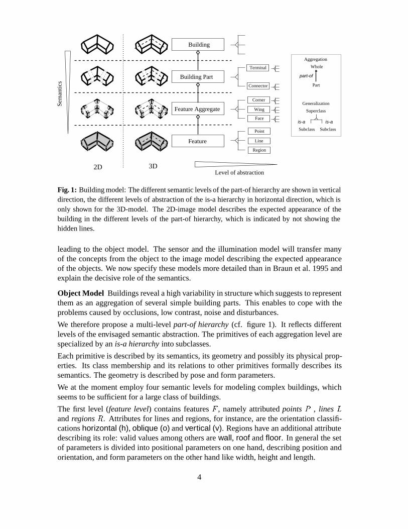
Fig. 1: Building model: The different semantic levels of the part-of hierarchy are shown in verticaldirection, the different levels of abstraction of the is-a hierarchy in horizontal direction, which isonly shown for the 3D-model. The 2D-image model describes the expected appearance of thebuilding in the different levels of the part-of hierarchy, which is indicated by not showing thehidden lines.
leading to the object model. The sensor and the illumination model will transfer manyof the concepts from the object to the image model describing the expected appearanceof the objects. We now specify these models more detailed than in Braun et al. 1995 andexplain the decisive role of the semantics.
Object Model Buildings reveal a high variability in structure which suggests to representthem as an aggregation of several simple building parts. This enables to cope with theproblems caused by occlusions, low contrast, noise and disturbances.
We therefore propose a multi-level part-of hierarchy (cf. figure 1). It reflects differentlevels of the envisaged semantic abstraction. The primitives of each aggregation level arespecialized by an is-a hierarchy into subclasses.
Each primitive is described by its semantics, its geometry and possibly its physical prop-erties. Its class membership and its relations to other primitives formally describes itssemantics. The geometry is described by pose and form parameters.
We at the moment employ four semantic levels for modeling complex buildings, whichseems to be sufficient for a large class of buildings.
The first level (feature level) contains features F , namely attributed points P , lines L
and regions R. Attributes for lines and regions, for instance, are the orientation classifi-cations horizontal (h), oblique (o) and vertical (v). Regions have an additional attributedescribing its role: valid values among others are wall, roof and floor. In general the setof parameters is divided into positional parameters on one hand, describing position andorientation, and form parameters on the other hand like width, height and length.
4

The second level (feature aggregate level) contains feature aggregates A which are in-duced by points, lines and regions, and contain all their direct neighbors. Each aggregateis defined by a feature graph, given by a set F � ff�� � � � � fkg of features and adjacencyrelations R � F � F . A Corner C , for instance, contains one point and all its adjacentlines and regions (cf. fig. 2).
0
2
2
0
l r
l
rl
1
r
1
2l
r1
l1
0r
0l
r2
p
Fig. 2: A corner is a feature neighborhood of a point (left). Drawn as graph the arcs express theadjacency relation (mid). Assuming no occlusions and disturbances its expected appearance in theimage reveals the same neighborhood relations between the corresponding 2D-features (right).
The third level (building part level) contains building parts P . Currently, they are definedas corner graphs given by a set C � fc�� � � � � cng of corners and adjacency relationsR � C � C . They are parameterized volumetric objects. Each building part has at leastone so called plug face which is used for connecting building primitives to each other.We discriminate terminals having exactly one plug face and connectors with two or moreplug faces (cf. figure 3).
Terminals: Connectors:
Fig. 3: Some examples of building parts. Plug faces, which are used to connect them, are drawndashed.
The fourth level (building level) contains complete buildings. Buildings are defined asgraphs with building parts as nodes, the arcs representing pairs of building parts connectedby corresponding plug faces. Thus, the most simple building consists of two connectedterminals.
Image Model The 2D image model describes the expected appearance of the buildingat the same levels of aggregation as the corresponding 3D-structures.1 This guaranteescoherence of the representation of 2D- and 3D-primitives being the prerequisite for allprocesses of 3D-reconstruction, aggregation, indexing and matching.
1Actually the image model contains the raster image as the lowest, say 0th level, from which the imagefeatures are extracted. This lowest level is not shown as we do not explicitely refer to it.
5
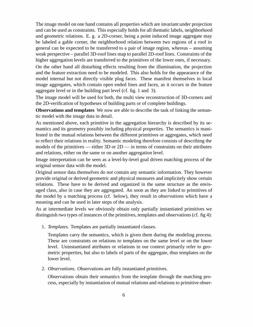
The image model on one hand contains all properties which are invariant under projectionand can be used as constraints. This especially holds for all thematic labels, neighborhoodand geometric relations. E. g. a 2D-corner, being a point induced image aggregate maybe labeled a gable corner, the neighborhood relation between two regions of a roof ingeneral can be expected to be transferred to a pair of image region, whereas – assumingweak perspective – parallel 3D-roof lines map to parallel 2D-roof lines. Constraints of thehigher aggregation levels are transferred to the primitives of the lower ones, if necessary.On the other hand all disturbing effects resulting from the illumination, the projectionand the feature extraction need to be modeled. This also holds for the appearance of themodel internal but not directly visible plug faces. These manifest themselves in localimage aggregates, which contain open ended lines and faces, as it occurs in the featureaggregate level or in the building part level (cf. fig. 1 and 3).The image model will be used for both, the multi view reconstruction of 3D-corners andthe 2D-verification of hypotheses of building parts or of complete buildings.Observations and templates We now are able to describe the task of linking the seman-tic model with the image data in detail.As mentioned above, each primitive in the aggregation hierarchy is described by its se-mantics and its geometry possibly including physical properties. The semantics is mani-fested in the mutual relations between the different primitives or aggregates, which needto reflect their relations in reality. Semantic modeling therefore consists of describing themodels of the primitives — either 3D or 2D — in terms of constraints on their attributesand relations, either on the same or on another aggregation level.Image interpretation can be seen as a level-by-level goal driven matching process of theoriginal sensor data with the model.Original sensor data themselves do not contain any semantic information. They howeverprovide original or derived geometric and physical measures and implicitely show certainrelations. These have to be derived and organized in the same structure as the envis-aged class, also in case they are aggregated. An soon as they are linked to primitives ofthe model by a matching process (cf. below), they result in observations which have ameaning and can be used in later steps of the analysis.As at intermediate levels we obviously obtain only partially instantiated primitives wedistinguish two types of instances of the primitives, templates and observations (cf. fig 4):
1. Templates. Templates are partially instantiated classes.
Templates carry the semantics, which is given them during the modeling process.These are constraints on relations to templates on the same level or on the lowerlevel. Uninstantiated attributes or relations in our context primarily refer to geo-metric properties, but also to labels of parts of the aggregate, thus templates on thelower level.
2. Observations. Observations are fully instantiated primitives.
Observations obtain their semantics from the template through the matching pro-cess, especially by instantiation of mutual relations and relations to primitive obser-
6
Pred
ictio
n / D
ecom
posi
tion
primitivestemplates observationsprimitive primitive
Aggregation / C
omposition
Relations
Relations
matching
aggregatessaggregatetemplates observations
aggregateinstance-of instance-of
instance-of instance-of
datamodel
trigger result
triggers results in
uses uses
Fig. 4: Templates and observations as partially and fully instantiated primitives. Observationsresult from image data by a matching process.
vations. Observations can be seen as interpreted image data at a certain level of theaggregation hierarchy.
2.2 Strategy
We employ a combined, data-driven and model-driven strategy integrated in a matchingprocess (cf. Fig. 4). It always links two levels within the part-of-hierarchy: Cornerreconstruction links the feature and the feature aggregate level, reconstructing buildingparts or buildings links the feature aggregate level with the building part or the buildinglevel, whereas the verification step links the feature level with the building part or thebuilding level.
The matching consists of four steps:
1. Trigger: The matching is triggered by a selected template at the higher level e. g. acorner, thus initiated by the semantic model. It can be seen as a set of goals. Theyhave the same structure, e. g. corner�type� geometry�, allowing to handle themindependently on the specific instance.
2. Prediction: The selected goals are used to predict a set of primitive templates onthe lower level. They also reveal the same structure and in addition are linked by aset of compatibility relations, which are given by the aggregate template.
3. Grouping: Based on the predicted components the primitive observations on thelower level, which play the role of the data in the matching process, are grouped.
7

E
A
B
C
D
1
Building parts
Cornerssem
anti
cs
Component E
Component A
Component C
Component D
Component B
Aggregate 1
aggregated components
interpretation
Fig. 5: Grouping and aggregation: componentsA toE being corners are grouped. Matching leadsto a building part as aggregate (excludingE) and labeling it as a terminal gable front.
Groups thus are candidates for higher level aggregates. E. g. when looking for cor-ners, point induced image structures are established. If strong positional knowledgeis available, e. g. when verifying buildings or building parts, grouping consists offinding equivalent primitives, e. g. collinear straight line segments. The data struc-ture of the groups is given by the aggregate template. However, no final interpre-tation takes place as grouping not necessarily checks the mutual relations betweenthe primitives simultaneously.
4. Aggregation: The aggregate template is now matched to the found groups, estab-lishing information at the higher level of the hierarchy. In this step all constraints onthe geometry, the radiometry and possibly on the semantics of the primitives at thelower level are used. This way primitives contained in the groups may be excluded,cf. Fig. 5, where primitive E is grouped but not aggregated. The matching transfersthe semantics of the templates, being part of the model, to the grouped data. Thisway the groups are interpreted, leading to aggregates which have a specific mean-ing within the model, e. g. labeling a corner as a gable corner. Using the part-ofhierarchy, also missing semantic labels for the primitives on the lower level of thehierarchy are established, indexing them into one of the prespecified classes, e. g.labeling a horizontal 3D-line segment of a vertex as gable point line(h).
2.3 The Procedure
The complete process can be described in the following way: Our input data are givenas digital raster images with multiple overlap. Further information about the aerial imageflight like exterior and interior camera orientation and time stamp are used. The start-ing point of our analysis is the extraction of a polymorphic image description consistingof points P �D, lines L�D and regions R�D and their mutual relations (cf. Forstner 1994,Fuchs and Forstner 1995). It allows to derive point, line and region neighborhood aggre-gates A�D, where vertices V �D are the most promising ones for starting our analysis.
8
Building
Viewparts
Vertices
Features 3D-Features
Corners
Buildingparts
3D2D
Views
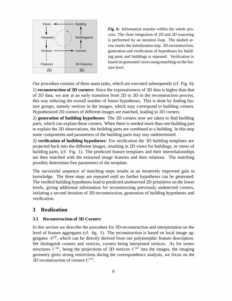
Fig. 6: Information transfer within the whole pro-cess. The close integration of 2D and 3D reasoningis performed by an iteration loop. The dashed ar-row marks the initialization step. 3D-reconstruction,generation and verification of hypotheses for build-ing parts and buildings is repeated. Verification isbased on generated views using matching on the fea-ture level.
Our procedure consists of three main tasks, which are executed subsequently (cf. Fig. 6):1) reconstruction of 3D corners: Since the expressiveness of 3D data is higher than thatof 2D data, we aim at an early transition from 2D to 3D in the reconstruction process,this way reducing the overall number of future hypotheses. This is done by finding fea-ture groups, namely vertices in the images, which may correspond to building corners.Hypothesized 2D corners of different images are matched, leading to 3D corners.2) generation of building hypotheses: The 3D corners now are taken to find buildingparts, which can explain these corners. When there is needed more than one building partto explain the 3D observations, the building parts are combined to a building. In this stepsome components and parameters of the building parts may stay undetermined.3) verification of building hypotheses: For verification the 3D building templates areprojected back into the different images, resulting in 2D views for buildings, or views ofbuilding parts, (cf. Fig. 1). The predicted feature templates and their interrelationshipsare then matched with the extracted image features and their relations. The matchingpossibly determines free parameters of the template.
The successful sequence of matching steps results in an iteratively improved gain inknowledge. The three steps are repeated until no further hypotheses can be generated:The verified building hypotheses lead to predicted unobserved 2D primitives on the lowerlevels, giving additional information for reconstructing previously undetected corners,initiating a second iteration of 3D-reconstruction, generation of building hypotheses andverification.
3 Realization
3.1 Reconstruction of 3D Corners
In this section we describe the procedure for 3D-reconstruction and interpretation on thelevel of feature aggregates (cf. fig. 1). The reconstruction is based on local image ag-gregates A�D, which can be directly derived from our polymorphic feature description.We distinguish corners and vertices, corners being interpreted vertices. As for vertexstructures V �D, being the projections of 3D vertices V �D into the images, the imaginggeometry gives strong restrictions during the correspondence analysis, we focus on the3D reconstruction of corners C�D.
9

Corner Model Corners are specialized into different subclasses. Each corner is describedby the corner point, several lines and planar faces (cf. fig. 2). The partitioning of cornersis described by their line attribution, given by the semantic labels (h), (v) or (o) (cf. Gulch1992). This description is further refined by distinguishing vertical and oblique lines dueto their slope into (v+), (v-), (o+) and (o-). Finally, different geometric constaints betweenthe corner components like e. g. symmetry and orthogonality are considered.We also model corner pairs. The previous classification of single corners is used forderiving restrictions like collinearity of lines and coplanarity of planes on compatiblecorner pairs.All these semantic attributed subclasses are collected in the set �C , one element for in-stance being the quadruple f (h), (o-), (o-), symmetry (o-,o-) g, which corresponds tothe vertex at the ridge of a hip roof.
Construction of Corner Hypotheses Starting point for the analysis are the 2D ver-tices V �D (cf. section 2.3). In the first step we generate 3D vertices. Selected tu-ples of corresponding vertex structures form the basis for the transition to 3D-verticesV �D � fv�D
�� � � � � v�Dn g by a joint forward intersection of all corresponding 2D-vertices
v�D � �v�D
�� � � � � v�DN �. It is established by heuristically selecting a suitable sequence of
vertices, which are then evaluated. The correspondence analysis uses the epipolar ge-ometry and the structural similarity of matching candidates. Relational matching of thefeatures F �D, which describe the vertex structures v�Di of the correspondence tuple v�D,leads to a 3D Vertex v�D.
Establishing corner hypotheses uses the corner model in the following way. We inter-pret the generated 3D vertices V �D by a first classification, leading to admissible cornersubclasses �C . First, the line attributation is used to obtain a subset ��
C of �C , which incase the line attributations do not correspond to a valid corner description, is the emptyset. For each element of ��
C the geometric constraints, associated by the model, yield afurther reduced ���
C � ��
C , each element in ���
C being an admissable interpretation of thevertex v�D. This way we obtain several corner hypotheses c�D.This principle of domain reduction of possible interpretations is also applied for the gen-eration of corner pairs �c�Di � c�Dj �.
Verification of Corner Hypotheses As the corner classification for each vertex v�D gen-erally will be ambiguous, we perform a second rigorous classification by statistical anal-ysis. This is an optimization problem for finding the best interpretation of the data. Foreach hypothesis, we estimate the geometric (and probably radiometric) parameters by amaximum likelihood parameter estimation. The functional model describes the relationbetween observations and the unknown parameters for the unconstrained corner. Addi-tionally hard and soft constraints ��D
�C, given by the corner class �C , are introduced. The
result of the estimations are evaluated corner reconstructions c�D � c�D�v�D� �C�. As-suming the same image feature observations, all possible corners are tested against theunconstrained corner to decide for the optimal interpretation of the vertex data v�D.Further details of the corner reconstruction approach can be found in (cf. Lang andForstner 1996b, Brunn et al. 1996).
The geometric constraints on single corners c�Di as well as on corner pairs �c�Dj � c�Dk �
10

h,o+,v-
h,o-,o-h,o-,o-
h,o+,v-
h,o-,o- h,o-,o-
h,o-,o-
h,o-,o-
o+,o-
o+,h
Fig. 7: Examples of 3D corner reconstruction. From left to right: feature aggregates marked inone image, reconstructed 3D corners, corner graph showing the adjacency relations.
are fundamental for a geometrically improved and verified corner reconstruction. Thosecorners C�D, which are accepted, are regarded as 3D-observations of the level featureaggregates and form the basis for the 3D aggregation. The grouping of corners resultsin a weighted graph G � �C�D� R� where the nodes are classified corners and the arcsthe adjacency relation. The weight of the arc expresses the conditional probability ofthe adjacency relation as derived from the classification. This forms the basis for thegeneration of building hypotheses as presented in the next chapter.After the first iteration of the whole building reconstruction process, we use newly gener-ated 2D corners C�D (cf. section 3.3), in addition to the original vertex data.
3.2 Generation of Building Hypotheses
Building hypotheses are generated from the observed corner graph G � �C�D� R� in atwo step process. First the corners are grouped and aggregated to building part templates.In the second step these building part templates are grouped and aggrated to buildingtemplates (cf. Fischer and Steinhage 1997).Generation of building part templates Since building parts are defined by corner graphsGj , the generation of building part templates explaining the corner observations is doneby determination of maximal subsets C�D�
i � C�D that have a subgraph isomorphismfrom �C�D�
i � R�� onto a Gj . That is, corner observations and templates must have the sameclassifications and adjacency relations.If a subgraph isomorphism of a �C�D�� R�� in a graph Gj of a building part p is found, theelements of C�D� are aggregated to a new building part template �p.Generation of building templates For the generation of building part templates struc-tural and geometrical information are considered. In general not all building parts forminga building have corner observations. Therefore it may be necessary to hypothesize build-ing part templates without having actual observations for them.
11

Buildings are constructed by grouping building parts. Our generic model allows groupsof variable size as long as restrictions on pairs of building parts implied by the model aresatisfied.The grouping task is defined by iterating the following steps. Starting with the set T� ofpreviously generated building part templates more complex templates are generated bymerging compatible pairs of building parts. Merging two parts implies the unificationof certain parameters and the introduction of a new length parameter (cf. fig. 8). Twobuilding parts may be merged, if their plug faces are of the same type and they havecompatible geometry. The latter is checked by parameter estimation. The previous step isiterated until either all elements of T� are part of a complete building with no plug facesor no new connections can be made.If the first condition holds we are done, because the complete buildings in the final setT contain all elements of T� and therefore explain all corner observations. Otherwise,not every building part template in T� is part of a complete building in T . In order toassign every element in T� to a complete building, new building part templates have to beintroduced for which there exist no observations. These parts must enable the constructionof new complete buildings, consisting of as few parts as possible. Every complete buildingrepresents a building template, which is a valid aggregation of building parts.For every building template a global parameter estimation considering all associated cor-ner observations determines the degree of freedom for every parameter.Generation of 2D view hierarchy For verification and determination of free parametersof the generated building hypotheses, represented by the building templates, they haveto be matched with the observations in the image. In 2D, buildings are modeled by viewhierarchies. With respect to the fixed image geometry all topologically different aspects ofthe buildings correspond to primitives on the highest level of the view hierarchy, definingthe 2D building templates. In contrast to aspect graphs the viewing direction is fixed,but due to free parameters the object geometry is in general variable, which can leadto different possible aspects. After the generation of the 2D building templates, theyare decomposed into primitives and their interrelationships on lower levels. A relationbetween primitives on a higher level is transformed to a set of relations beween theircomponents on the lower level. Thereby semantic knowledge is propagated down throughevery level of our aggregation hierarchy. For each image one view hierarchy is generated.
3.3 Verification of Building Hypotheses
The generation of 3D building hypotheses leads to different possible 2D views. Sincesome parameters of the 3D building templates may still be free, there are free parameters
z
y
y’
x’z’
x
sh
rh
w
w’
h’r
h’s
z
yx
wd
hs
hr
Fig. 8: The parameters w andw�, hs and h�s, and hr and h�r are
unified. The parameter d is in-troduced to describe the depth ofthe newly formed building.
12
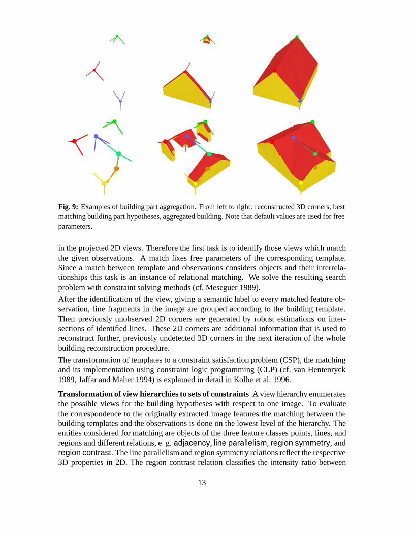
Fig. 9: Examples of building part aggregation. From left to right: reconstructed 3D corners, bestmatching building part hypotheses, aggregated building. Note that default values are used for freeparameters.
in the projected 2D views. Therefore the first task is to identify those views which matchthe given observations. A match fixes free parameters of the corresponding template.Since a match between template and observations considers objects and their interrela-tionships this task is an instance of relational matching. We solve the resulting searchproblem with constraint solving methods (cf. Meseguer 1989).
After the identification of the view, giving a semantic label to every matched feature ob-servation, line fragments in the image are grouped according to the building template.Then previously unobserved 2D corners are generated by robust estimations on inter-sections of identified lines. These 2D corners are additional information that is used toreconstruct further, previously undetected 3D corners in the next iteration of the wholebuilding reconstruction procedure.
The transformation of templates to a constraint satisfaction problem (CSP), the matchingand its implementation using constraint logic programming (CLP) (cf. van Hentenryck1989, Jaffar and Maher 1994) is explained in detail in Kolbe et al. 1996.
Transformation of view hierarchies to sets of constraints A view hierarchy enumeratesthe possible views for the building hypotheses with respect to one image. To evaluatethe correspondence to the originally extracted image features the matching between thebuilding templates and the observations is done on the lowest level of the hierarchy. Theentities considered for matching are objects of the three feature classes points, lines, andregions and different relations, e. g. adjacency, line parallelism, region symmetry, andregion contrast. The line parallelism and region symmetry relations reflect the respective3D properties in 2D. The region contrast relation classifies the intensity ratio between
13
adjacent regions.
A building template there is represented by a set of features and a set of relations betweenthem. These relations may be regarded as a set of constraints which have to be satisfiedsimultaneously by the corresponding objects. A consistent match is an identification of aset of objects which satisfies all constraints. The decomposition of the matching probleminto the simultaneous satisfaction of different constraints leads to a structure which isadequately represented by the translation of templates into conjunctions of constraintswhere the features are represented by variables with restricted domains. The domain ofa variable depends on its associated model feature type, for instance line variables arerestricted to the set of line observations that were extracted from the image. Thus the firstconstraint posed on a variable is the domain constraint. All other constraints are impliedby the corresponding relations of the building template.
For each view of a hierarchy one set of constraints will be generated representing thebuilding template.
Matching of constraint sets to the image data The matching is done seperately forevery image and view by searching for a valid assignment of extracted image features tothe variables of the corresponding CSP, such that all constraints are satisfied. Consistencytechniques exploit the structured representation of the matching problem as a constraintnetwork. The idea is that a constraint is used to restrict the domains of its variables andthat these reductions are propagated through the network.
Standard techniques for constraint solving (Mackworth 1977, Haralick and Elliott1980, Dechter and Pearl 1988, van Hentenryck 1989) demand that a match satisifies ev-ery constraint. Due to occlusions and disturbances in general neither every predictedmodel feature of a view can be found nor all their incident constraints are satisfiable.To cope with this problem we employ relaxation of constraints, allowing constraints tobe neglected. Our combination of consistency techniques and constraint relaxation fol-lows in general the scheme described in Haralick and Shapiro 1993 for inexact matching.As a language constraint logic programming provides hard constraints which are strictlyenforced. A soft constraint c�t�� � � � � tn��� with n � � arguments may be implementedby a hard constraint c��t�� � � � � tn��� b� where c� is satisfied if the boolean b is true or cis satisfied. The variable b with the domain ftrue� falseg may act as a communicationchannel between the constraint and its environment. This environment may come to theconclusion that c models an unobservable relation and relaxes c by instantiating b withtrue.
The solution of the constraint satisfaction problem are the valid assignments of extractedfeatures to the variables. On the one hand these assignments determine the free geomet-ric parameters of the feature templates and thus determine free parameters of the wholebuilding template. On the other hand, every assigned image feature is identified as a spe-cific component of the building observation as defined by the building template. Thesematched image features are given labels, denoting their semantics with respect to thebuilding model. Figure 10 shows on the left highlighted the image features that weresuccessfully matched with the building template for a saddle roof house.
Since lines in general are fragmented into several line image features, corresponding line
14

Fig. 10: Left: Matched features, right: new 2D corners
features are grouped and fitted using the labeling information to determine the lines of thebuilding observation.
Generation of new 2D corners The solution of the CSP in general fixes further parame-ters of the building template. It has to be noted, that free parameters may remain, if someconstraints had to be relaxed. Corners of the building template with fixed positions thathave no corresponding observation of a vertex structure in the image, finally are recon-structed in 2D as illustrated by the right picture in figure 10 to provide new informationfor the 3D corner reconstruction in the next iteration of the reconstruction process.
As mentioned above the loop of 3D-reconstruction and generation and verification ofbuilding hypotheses will be terminated if no further hypotheses can be generated. Afterthe final verification step the parameters of the 3D-building model will be determined si-multaneously based on the observed image features and taking all geometric and possiblyradiometric constraints into account.
3.4 Results
The actual result of the reconstruction procedure is presented for the international testdata set which was distributed for the Ascona Workshop 1995 on Automatic Extractionof Man-Made Objects from Aerial and Space Images (cf. Grun et al. 1995). The imagescale is � � and we use a resolution with ��m pixel size in contrast to Bignone etal. 1996 who use ��m. As building h12 is under construction, only 11 out of the 12buildings which are contained in multiple images, are relevant for the analysis. To test thefeasibility of the concept in a first instance the number of building primitives is reduced to2 different building part terminals and their possible connectors. To resolve the footprintof the buildings, higher image resolution is necessary. Thus building heights can not bedetermined automatically and therefore are set to fixed values. Figure 11 shows the resultafter the first iteration loop (cf. Fig. 6). Results of the intermediate steps are listed inTable 1 and reflect the following aspects of the different reasoning steps:Reconstruction of 3D corners (I): The number of reconstructed corners RC on averagecompounds � of the buildings corners (C), whereas � of them are incorrectely classi-
15

h12
h11
h9 h10
h3
h6
h8
h7
h4h2
h5
h1
Fig. 11: Visualization ofthe reconstruction resultfor the Ascona Datset af-ter one iteration loop (cf.Fig. 6) is performed. Theimages contain 12 build-ings in multiple overlap.As building h12 is underconstruction, we excludedit from our analysis. Weare able to completely re-construct 10 of the 11buildings which were rel-evant for the analysis.
fied. We are not able to completely reconstruct every corner, because not all corners areobservable in the symbolic image descriptions. An application indepent grouping as pre-sented in Fuchs and Forstner 1995 may improve the initial symbolic image descriptions.Possibly still remaining unreconstructed corners have to be identified during the verifi-cation step of building hypotheses. The reason for incorrect classification is given by aweak intersection geometry for the line reconstruction, which is not yet considered in themodeling process. Neglecting the influence of the uncertainity of the line reconstruction,the corner point is correctely reconstructed. Actually the identification of wrong cornerinterpretations is performed by finding global inconsistencies during the generation ofbuilding hypotheses. For building h10 the image resolution is not sufficient to success-fully reconstruct any corner. The parameter estimation for correctely classified cornersusing 4 images simultaneously achieves an accuracy of the reconstructed corner pointabout �x � �y � ��cm and �z � ��cm. The accuracy of the orientation of the cornersis about �� � ��o while the reconstruction of the slope of the roof is by �sl � �o.
Generation of building hypotheses (II): The column BPH gives the number of buildingpart hypotheses which are generated for each of the reconstructed single corners. Thecombination of these building parts results in the number BH of hypotheses of completebuildings which are consistent with all reconstructed corners. If only one corner is given,as it is the case for h2 and h7, the corresponding terminals are each completed to a closedbuilding hypothesis with a second terminal of the same type. For each of the BH buildinghypotheses the view graph is generated. Currently the view graph of the best buildinghypothesis is passed to the verification of building hypotheses. The decision which is the
16

I II IIIBuilding C RC CE BPH BH UV GV FPh1 6 3 0 3/4/3 4 3 3/3/3/3 0h2 6 1 0 3 2 5 5/5/-/- 0h3 12 7 0 3/3/2/3/3/4/0 4 5 -/-/-/- 0h4 6 3 0 4/3/3 4 3 3/3/3/3 0h5 6 3 0 3/4/4 4 3 3/3/3/3 0h6 6 3 1 3/0/4 4 4 4/4/4/4 0h7 6 2 1 3/0 2 5 5/5/5/5 0h8 6 3 0 3/3/4 4 3 3/3/3/3 0h9 6 4 0 3/3/4/8 2 2 2/2/2/2 0h10 10 0 - - - - - -h11 6 2 0 3/3 4 4 4/4/1/0 0
C number of corners of the buildingRC number of reconstructed cornersCE number of corner classification errorsBPH number of building part hypotheses
for each corner
BH number of building hypothesesUV predicted cornersGV predicted and verified vertices
per imageFP remaining free parameters
Tab. 1: Detailed results of the intermediate reconstruction processes Reconstruction of 3D corners(I), Generation of building hypotheses (II) and Verification of building hypotheses(III) for theAscona Dataset. 10 of the 11 buildings can be reconstructed as shown in column FP.
best one is given by using the Minimum Description Length criterium following Rissanen1987.
Verification of building hypotheses(III): For each building in each image one viewgraph being a building template is available and matched to the extracted image fea-tures and mutual relations. Column UV lists the number of corners which were correctlypredicted during the generation of building hypotheses. The column GV shows for eachof the 4 images the number of correctly matched vertices. For � of the images a suc-cessful matching is reached, 9 of the 10 generated building hypotheses could be verifiedby successful matching in at least one image. Dashes in the table denote a break-off ofthe analysis with complex or strongly underconstrained models, which can be resolvedusing appriopriate heuristics to keep the search space down. As for the buildings h3 thereconstructed corners already were sufficient to determine all parameters of the buildinghypothesis, in 10 of the 11 examples the building is successfully reconstructed as shownin the last column FP of the table.
4 Conclusions and Outlook
We have proposed a model-based approach to 3D building extraction from aerial images.Our modeling concept reveals a tight coupling of generic 3D object modeling and anexplicit image model. Object and image model show corresponding part-of hierarchiesdescribing aggregation states within a recognition-by-components strategy.
17
The procedure aims at a step by step increase of knowledge during the reasoning. As thesemantics of a model defines the maximum achievable knowledge about an actual sceneand its granularity determines the resolution for knowledge our model spans hierarchi-cally from the smallest observable features to complex buildings and allows an adequateevaluation of hypotheses and their immanent knowledge within the different reasoningsteps.We have presented first experimental results on test data sets provided by the Landesver-messungsamt Bonn and the ETH Zurich.Currently we are investigating and developing on
� the measurement and propagation of uncertainty within the overall reconstructionprocess;
� the extension of the current building modeling by more sophisticated knowledgeabout buildings, esp. functional aspects.
� the derivation of domain dependent heuristics to constrain search spaces;
� the handling of incomplete observations within all processes and stages of hypothe-ses generation and verification.
Especially we have to consider the integration of hard and soft constraints, i. e. logical andstatistical knowledge into the framework of constraint logic programming. Furthermorethe approach has to be compared to different automatic algorithms for segmentation, 3Dreconstruction and classical photogrammetry. In order to achieve this goal an attempt ismade to find a set of standardized notions about basic building models, parts of buildingsand classes of buildings to ease such comparisons on a conceptual level.
Acknowledgments:
This work was largely done within the the project “Semantic Modeling and Extractionof Spatial Objects from Images and Maps” especially in the subproject “Building Extrac-tion” which is supported by the Deutsche Forschungsgemeinschaft. We heavily profittedfrom discussions with Armin B. Cremers, Wolfgang Forstner, Lutz Plumer and VolkerSteinhage. We thank the DFG for supporting our work.
References
Bergevin R., M. Levine (1993) Generic object recognition: Building and matching coarsedescriptions from line drawings, IEEE T-PAMI, Vol. 15, No. 1, pp. 19–36.
Biederman I. (1987) Recognition-by-components: A theory of human image under-standing, Psychological Review, Vol. 94, pp. 115–147.
Bignone F., O. Henricsson, P. Fua, M. Stricker (1996) Automatic extraction of generichouse roofs from high resolution aerial images, Computer Vision — ECCV ’96, Proc. of
18
the 4th Europ. Conf. on Computer Vision, number 1064 in Lecture Notes in ComputerScience, pp. 85–96.
Braun C. (1994) Interpretation von Einzelbildern zur Gebaudeerfassung, PhD thesis,Institut fur Photogrammetrie, Universitat Bonn.
Braun C., T. H. Kolbe, F. Lang, W. Schickler, V. Steinhage, A. B. Cremers, W. Forstner,L. Plumer (1995) Models for photogrammetric building reconstruction, Computer �Graphics.
Brunn A., F. Lang, W. Forstner (1996) A procedure for segmenting surfaces by symbolicand iconic image fusion, in B. Jahne, P. Geißler, H. Haußecker, F. Hering (eds), Muster-erkennung 1996, DAGM, Springer, pp. 11–20.
Clowes M. (1971) On seeing things, Artificial Intelligence, Vol. 2, pp. 79–116.
Dechter R., J. Pearl (1988) Network-based heuristics for constraint satisfaction problems,Artificial Intelligence.
Dickinson S. J., A. P. Pentland, A. Rosenfeld (1992) From volumes to views: An approachto 3-d object recognition, CVGIP: Image Understanding, Vol. 55, No. 2, pp. 130–154.
Fischer A., V. Steinhage (1997) Solid modeling for building extraction from aerial images,in V. Skala (ed.), 5th Int. Conf. in Central Europe on Computer Graphics and Visualization97, WSCG’97, pp. 114–123.
Flynn P. J., A. K. Jain (1991) Cad-based computer vision: From cad-models to relationalgraphs, IEEE T-PAMI, Vol. 13, No. 2, pp. 114–132.
Forstner W. (1994) A framework for low level feature extraction, in J.-O. Eklundh (ed.),Computer Vision, ECCV ’94, Vol. II, number 801 in Lecture Notes in Computer Science,Springer-Verlag, pp. 383–394.
Fua P., A. J. Hanson (1987) Resegmentation using generic shape: Locating generalcultural objects, Pattern Recognition Letters, Vol. 5, pp. 243–252.
Fuchs C., W. Forstner (1995) Polymorphic grouping for image segmentation, Proceedings5th International Conference on Computer Vision, pp. 175–182.
Grun A., O. Kubler, P. Agouris (eds) (1995) Automatic Extraction of Man-Made Objectsfrom Aerial and Space Images, Birkhauser.
Gulch E. (1992) A knowledge-based approach to reconstruct buildings in digital aerialimagery, 17th ISPRS Congress, Washington D. C., Proceedings, pp. 410–417.
Hansen C., T. C. Henderson (1993) Cad-based computer vision, IEEE T-PAMI, Vol. 11,pp. 1187–1193.
19
Haralick R. M., G. L. Elliott (1980) Increasing tree search efficiency for constraint satis-faction problems, Artificial Intelligence, Vol. 14, pp. 263–313.
Haralick R. M., L. G. Shapiro (1993) Computer and Robot Vision, Vol. II, Addison-Wesley Publishing Company.
Herman M., T. Kanade (1987) The 3d mosaic scene understanding system: Incrementalrecognition of 3d scenes from complex images, in Fischler/Firschein (ed.), Readings inComputer Vision, Kaufmann, pp. 471–482.
Heyden A. (1994) Consistency and correction of line-drawings, obtained by projectionsof piecewise planar objects, Computer Vision — ECCV ’94, Proc. of the 3rd Europ. Conf.on Computer Vision, number 800 in Lecture Notes in Computer Science, pp. 411–419.
Huertas A., M. Benjanin, R. Nevatia (1995) Model registration and validation, inA. Grun, O. Kubler, P. Agouris (eds), Automatic Extraction of Man-Made Objects fromAerial and Space Images, Birkhauser, Basel, pp. 33–43.
Huffman D. A. (1971) Impossible objects as nonsense sentence, Machine Intelligence 6,pp. 295–323.
Ikeuchi K., P. J. Flynn (1995) Recent progress in cad-based vision, CVGIP, Vol. 61, No. 3,pp. 293–294.
Jaffar J., M. J. Maher (1994) Constraint logic programming: A survey, Journal of LogicProgramming.
Kanatani K. (1990) Group-Theoretical Methods in Image Understanding, Springer.
Kolbe T. H., L. Plumer, A. B. Cremers (1996) Using constraints for the identificationof buildings in aerial images, Proceedings of the 2. Int. Conf. on Practical Applicationsof Constraint Technology PACT’96 in London, The Practical Application Company Ltd.,pp. 143–154.
Lang F., W. Forstner (1996a) 3d-city modelling with a digital one-eye-stereo system,ISPRS Symposium, Comm. IV, Vienna.
Lang F., W. Forstner (1996b) Surface reconstruction of man-made objects using polymor-phic mid-level features and generic scene knowledge, Zeitschrift fur Photogrammetrie undFernerkundung, Vol. 6, pp. 193–201.
Lin C., A. Huertas, R. Nevatia (1994a) Detection of buildings using perceptual group-ing and shadowsproceedings computer vision and pattern recognition, Proceedings Com-puter Vision and Pattern Recognition, pp. 62–69.
Lin C., A. Huertas, R. Nevatia (1995) Detection of buildings from monocular images,Automatic Extraction of Man-Made Objects from Aerial and Space Images, pp. 125–134.
20

Lin C. L., Q. Zheng, R. Chelappa, L. S. Davis, X. Zhang (1994b) Site model sup-ported monitoring of arial images, Proceedings Computer Vision and Pattern Recogni-tion, pp. 694–699.
Mackworth A. K. (1977) Consistency in networks of relations, Artificial Intelligence,Vol. 8, pp. 99–118.
McKeown D. M. (1990) Towards automatic cartographic feature extraction from arialimagery, in H. Ebner, D. Fritsch, C. Heipcke (eds), Digital Photogrammetric Systems,Wichmann, Karlsruhe.
Meseguer P. (1989) Constraint satisfaction problems: An overview, AICOM, Vol. 2,No. 1, pp. 3–17.
Munkelt O. (1995) Aspect-trees: Generation and interpretation, CVGIP, Vol. 61, No. 3,pp. 365–386.
Quam L., T. Strat (1991) Sri image understanding research in cartographic feature extrac-tion, in C. H. H. Ebner, D. Fritsch (ed.), Digital Photogrammetric Systems, Wichmann,Karlsruhe, pp. 111–121.
Rissanen I. (1987) Minimum description length principle, Encyclopedia of StatisticalSciences, Vol. 5, pp. 523–527.
Schickler W. (1993) Towards automation in photogrammetry, Geodetical Info Magazine.
Sester M., W. Forstner (1989) Object location based on uncertain models, inH. Burkhardt, K.-H. Hohne, B. Neumann (eds), Mustererkennung 1989, 11. DAGM-Symposium, Hamburg, Vol. 219 of Informatik Fachbericht, Springer, pp. 457–464.
Suetens P., P. Fua, A. J. Hanson (1992) Computational strategies for object recognition,ACM Computing Surveys, Vol. 24, No. 1, pp. 5–61.
Sugihara K. (1986) Machine Interpretation of Line Drawings, MIT-Press.
van Hentenryck P. (1989) Constraint Satisfaction in Logic Programming, Logic Program-ming Series, MIT Press, Cambridge, MA.
Waltz D. L. (1975) Understanding line drawings of scenes with shadows, in P. H. Winston(ed.), Psychology of Computer Vision, McGraw-Hill, New York, pp. 19–91.
Weidner U. (1996) An approach to building extraction from digital surface models, IS-PRS.
Weidner U., W. Forstner (1995) Towards automatic building extraction from high resolu-tion digital elevation models, ISPRS Journal, Vol. 50, No. 4, pp. 38–49.
21