integration of design and construction of the tallest ... · structural system resulted in a cost...
TRANSCRIPT

Title: Integration of Design and Construction of the Tallest Building in Korea
Authors: Ahmad Abdelrazaq, Executive Director, Samsung E&CWilliam Baker, Partner, Skidmore, Owings & MerrillKwang Ryang Chung, Principal, Dong Yang Structural EngineersJ Pawlikowski, Vice President, Samsung E&CInsoo Wang, Manager, Samsung E&C
Subjects: Building Case StudyStructural Engineering
Keywords: ConcreteFoundationOutriggers
Publication Date: 2004
Original Publication: CTBUH 2004 Seoul Conference
Paper Type: 1. Book chapter/Part chapter2. Journal paper3. Conference proceeding4. Unpublished conference paper5. Magazine article6. Unpublished
© Council on Tall Buildings and Urban Habitat / Ahmad Abdelrazaq; William Baker; Kwang Ryang Chung; JPawlikowski; Insoo Wang
ctbuh.org/papers

654 CTBUH 2004 October 10~13, Seoul, Korea
Ahmad Abdelrazaq, Vice President / Executive Director Samsung Corporation, Engineering & Construction Group12 flr Samsung Plaza bldg. 263Seohyun, Bundang-Gu, Sungnam-Gu Gyonggi-Do, Korea 463-721 Tel: 82.2.2145.5190; Fax: 82.2.2145.5770, E-mail, [email protected]
Integration of Design and Construction of the Tallest Building in Korea, Tower Palace III, Seoul, Korea
A.K. Abdelrazaq1, W. F. Baker2, K.R. Chung3, J. Pawlikowski4, Insoo Wang 5, K.S. Yom6
1 Executive Director, Samsung Corporation, Engineering and Construction Group 2Partner, 4Associate, Skidmore, Owings & Merrill LLP, Chicago, USA 3Principal, Dong Yang Structural Engineering Co., Ltd, Seoul, Korea
4Vice President, 5Manager, Samsung Corporation, Construction & Engineering Group Abstract Tower Palace III was conceived as a 93-story residential tower soaring 320 meters into Seoul’s skyline. However, concerns of the local residents and authorities over the building height resulted in a 73-story tower with the same gross floor area. The early integration of aerodynamic shaping and wind engineering considerations played a major role in the architectural massing and design of the tower. The Contractor’s input in selecting the optimum structural system resulted in a cost effective tower that served the clients needs and the tower was completed ahead of schedule. This paper presents a brief overview of the structural system development of the tower and its direct integration with the construction aspects, discusses the construction planning of the key structural components of the tower, and briefly describes the monitoring program incorporated into the tower for the evaluation of time dependent deformation. Keywords: indirect outrigger belt-wall system, composite column instrumentation, self compacting/consolidating concrete, mat foundation, wind engineering integration with the architectural massing. 1. Introduction
Tower Palace III was part of Samsung Life Insurance Togok site development plan, which is located in the Kangnam district of Seoul, South Korea and consisted of three phases. Phases I and II included Tower Palace I and II development that comprised of six high-rise residential towers varying from 42 to 66 stories. Phase III of this development, Tower Palace III (TPIII), consisted of a 73-story single point tower with an adjacent eight (8) story sport center, and six (6) levels of parking below grade. Tower Palace III site development is located in a moderate wind climate and subject to moderate/low seismic forces. Early planning and concept envisioned this tower to be 320 meters high and an all-residential building. The critical design criteria for this very tall luxury residential tower called for controlling the dynamic response of the tower and managing its wind engineering aspects. During the design process, the building evolved into three different schemes, where each of the schemes was accepted by the client and fully studied at the Boundary Layer Wind Tunnel Laboratory (BLWTL), See Figure 2. Force balance
studies indicated that the tower massing, exterior wall treatment, and the dynamic building characteristics resulted in a structure that was not sensitive to dynamic wind excitations, and the predicted building acceleration and torsional velocities were below the internationally acceptable acceleration and torsional velocity criteria.
While the three schemes had the same gross floor area and approximately the same number of apartment units, the 93-story tower was not accepted by the
Figure 1: Tower Palace Development

CTBUH 2004 October 10~13, Seoul, Korea 655
neighbors due to its height and the potential for traffic congestion in the area. The 73-story tower, scheme 3, was finally selected by the client to satisfy the concerns of the local authorities and the neighbors.
This paper presents an overview of the
development of the tower’s structural system and its direct integration with the architectural massing and construction planning for the key structural components of the tower. In addition, this paper briefly discusses the instrumentation of the tower to evaluate the long term behavior of the composite columns and the reinforced concrete core wall. The strain measurements at the composite columns and the core wall correlated well with the predicted strains.
2. Structural System Design Approach
Structural System Design Approach The structural design process of the tower was
formulated based on the following goals: ♦ Optimize the tower structural system for strength,
stiffness, cost effectiveness, redundancy, and speed of construction.
♦ Manage and locate the gravity load resisting system so as to maximize its use in resisting the lateral loads while harmonizing with the architectural planning of a luxury residential tower.
♦ Incorporate the latest innovations in analysis, design, materials, and construction methods.
♦ Limit the building drift, acceleration, and torsional velocity to within the international accepted design criteria.
♦ Control the relative displacement between the vertical members, especially for composite buildings.
♦ Control the dynamic response of the tower under wind loading by tuning the structural characteristics of the building to improve its dynamic behavior and to prevent lock-in vibration due to the vortex shedding. Favorable dynamic behavior of the tower was achieved by:
a) Varying the building shape along the height
while continuing, without interruption, the building gravity and lateral load resisting system;
b) reducing the floor plan along the building’s upper zone; and
c) creating irregularities along the building’s exterior surfaces, thus reducing the local cladding pressures as well as the overall wind loads on the building structure.
Wind Engineering
Wind loads considered in the analysis of the tower structure were developed using the code defined load criteria as well as the results from the wind tunnel testing program, which is based on historical climatological data. The wind tunnel testing program, conducted at the Boundary Layer Wind Tunnel Laboratory (BLWTL) included 1) site proximity wind analysis model, 2) force balance tests, see Figure 3, conducted for all schemes, 3) cladding and pressure integration test, and 4) pedestrian wind studies.
The climatological study performed for the project was determined for a 100 year return period with a mean-hourly gradient wind speed of 41 m/s. This resulted in a wind pressure of 2.5kN/m2. Strength design of the tower was based on both the code-prescribed wind loads with exposure A and the wind tunnel developed 100-year return period. Wind tunnel recommendation included combining the wind loads in
a) 93-Story (320m) b) 77-Story (270m) c) 73-Story (264m) Scheme 1 Scheme 2 Scheme 3
Figure 2: Tower Palace III Massing Studies
93 Story Tower 77 story Tower 73 story Tower
Figure 3: Wind Tunnel Test Models

656 CTBUH 2004 October 10~13, Seoul, Korea
the orthogonal direction and torsional moments simultaneously. 1.5% and 2% damping were assumed for serviceability and strength design respectively. Seismic Considerations
TPIII is located in an area with low seismic activity and the building is essentially founded on rock foundation with locally fractured and weak layers of rocks. The seismic behavior and response of the tower was evaluated using the modal response spectrum analysis method. Response spectrum curves and loading conditions required by the Korean Building Law were utilized as a base for the seismic loading conditions. Since the building is very tall and flexible, the tower was controlled by wind design rather than seismic design except at the top of the building, where the whip lash effects generated forces that are slightly higher than the wind forces. The overall building drift and interstory drift met the Korean and UBC 97 building code requirements.
Foundation System Considerations The tower superstructure is founded on a 3500
mm high performance reinforced concrete mat over lean concrete slab over prepared rock. The rock quality and mechanical characteristics varied over the site in general and in particular at the footprint of the tower due to the presence of ancient faults and shear zones. These faults/shear zones started at approximately 7 meters north of the foundation mat to approximately 150 meters below the south edge of the foundation mat. The presence of these fault caused concerns about the behavior of the foundation system. The geotechnical engineering work, performed by Dames and Moore, San Francisco, CA, USA, indicated that these faults are inactive.
A 3-dimensional finite elements analysis model, using FLAC 3D, was utilized to model the entire rock mass/foundation mat in order to better estimate the foundation settlement and behavior. See figure 4.
Two FLAC3D foundation analysis models were performed to evaluate the impact of the faults on the settlement analysis. Comparison of the analysis results between the two models indicated that the overall building settlement was increased by approximately 23% due to the presence of the faults.
Because of the variation of the rock quality, the
presence of faults, and the shape of the building/structure, it was prudent to utilize a mat foundation system under the tower footprint in order to minimize the differential settlement, reduce the impact of the differential settlement on the superstructure member design, and to bridge over the local weak rock layers and pockets. Based on the 3DFLAC settlement analysis model, Dames & Moore provided the soil stiffness that was utilized as a basis for soil-structure analysis model of the tower.
The mat foundation analysis indicated that the
maximum anticipated settlement under the tower would be approximately 15mm. The building survey indicated that the actual foundation settlement was smaller than anticipated. Differential Axial Shortening Considerations
While optimizing the lateral load resisting system of the tower, minimizing the differential shortening, between the composite columns and the core wall, was one of the critical issues considered during the development of the structural system of the tower.
Figure 4: FLAC3D- Foundation Analysis model (Courtesy of Dames & Moore) Figure 5: Soil Structure Interaction Analysis Model

CTBUH 2004 October 10~13, Seoul, Korea 657
3. Structural System Description Floor Framing System
Several Floor framing system were considered for the tower, including a flat plate system and composite steel framing. However, because of the client marketing requirements, a composite floor framing system was selected. The composite floor framing system consisted of a 150mm composite metal deck slab spanning 3 to 4 meters between 400mm deep hot rolled composite steel beams, see Figure 5. The 400mm beam depth was selected to allow for MEP openings so that the ceiling sandwich is minimized. The composite structural steel beams were arranged to reduce the number of embedded plates into the core wall and were fireproofed with cementitious material to achieve the applicable fire rating. Lateral Load Resisting System
The lateral load resisting system of the tower provided resistance to wind and seismic forces and consisted of a high performance, reinforced concrete core wall system, from the foundation to the roof that was linked to the exterior composite columns by an indirect outrigger belt wall system at the mechanical levels (16 to 17, and 55 to 56). The interaction of the core wall system and the exterior columns was provided through deformation compatibility, resulting in significant forces in the belt wall system
components, which included the belt wall and the floor slabs. The core wall system
While the exterior flanges of the core wall vary in thickness from 550 mm at the bottom to 400 mm at the top, the interior core wall web thicknesses were maintained at 300mm throughout the building height. In a typical level, the core wall vertical wall components are rigidly connected by a series of 750mm deep composite or reinforced concrete link beams. The link beam widths typically match the adjacent core wall thicknesses.
a) Structural System Diagram b) Floor Framing Plan
Figure 5: Structural System Diagram & Typical Floor Framing Plan
55 Belt Wall
Exterior Columns
Core Wall
Mat Foundation
Exterior Columns
Interior Columns
R/C Core Wall System
Composite Floor Framing
16 Belt Wall
Figure 6: Composite Link Beam Details

658 CTBUH 2004 October 10~13, Seoul, Korea
Due to the link beam depth limitations, a composite structural steel beam was introduced at the locations where large shear and bending moment forces existed. See Figure 6. The composite link beam consisted of a built-up wide flanged structural steel beam or a single structural steel plate that were embedded in the concrete section. The structural steel web section, where required, was designed to resist the majority of the shear forces and the composite section was utilized in resisting the bending moments. Since the composite link beam section provides significant shear ductility, the bending moment forces in the link beams can be limited. Thus the maximum forces that the core wall system can attract in a seismic event can be managed, and the overall building behavior can be controlled without significant damage even in severe seismic event.
The exterior columns
The exterior columns of the tower are typically steel reinforced concrete columns (SRCC) that vary from 1350mm Diameter at subgrade levels, to a maximum of 1000x1000 from levels 4 to 56, to 900x900 from level 57 to 65, to 800x800 from the 66 level to the roof. In order to minimize the column size, concrete filled (CFT) with high strength concrete was considered for the exterior and interior columns at the conceptual design stage. However, SRC columns were adopted instead, in order to minimize the differential relative movement, due to immediate and long term deformations, between the exterior columns and the
core walls throughout the building life, and during the construction period. The indirect outrigger belt wall system
The indirect outrigger belt wall system is essentially similar to an outrigger wall system; however, the mechanism of force resolution between the core wall and the belt wall system is indirect, through the floor slabs rather than the direct wall connection. The indirect outrigger belt wall system consists of an exterior reinforced concrete perimeter wall that rigidly connects the exterior composite columns and the very stiff floor slabs.
The indirect outrigger belt walls for TPIII were located at the mechanical levels (16 and 55) and consisted of an 800mm wide by 8 meter high wall perimeter wall and a 300mm thick floor slabs, at the top and the bottom of the perimeter walls. While the high perimeter belt wall bending and shear stiffness connected the exterior composite columns rigidly, the floor slab high in-plane bending and shear stiffness forced deformation compatibility and shear force redistribution between the core wall and the exterior belt wall frame system.
Since the perimeter belt walls reduced the relative displacements between floors, the lateral system rotations at the belt wall levels were significantly reduced, and thus reducing the building lateral displacement significantly. The restraining effects of the exterior columns against the belt wall rotation resulted in axial loads in the exterior columns. These
Figure 7: Belt wall system load flow diagram between the core wall and the exterior belt wall system
CTBUH 2004 October 10~13, Seoul, Korea 659
axial forces were counter balanced by force couples into the belt wall system, which were then counter balanced by force couples into the slabs that are finally resisted by the interior core wall system.
The advantages of the indirect outrigger belt wall system over a more conventional direct outrigger wall system can be summarized as follows:
♦ Placement of the belt wall system at the perimeter did not restrict the mechanical floor space and allowed for freedom in placing the mechanical equipment in the plant space, thus reducing the amount of coordination work required between trades.
♦ The Construction of the belt wall system was not in the construction schedule critical path;
♦ The belt system did not have a direct link between the core wall and the exterior columns, and therefore eliminated one of the most difficult technical problems encountered in the design and detailing of the direct outrigger wall systems, which is the potential of generating large forces due to the differential movement between the core wall and the exterior columns; and
♦ The extensive detailing and construction sequence work required for the direct outrigger wall system is significantly reduced.
4. Construction Planning
Samsung Construction was involved with the design team from the early design stage in evaluating all building systems (structural, architectural, building services, etc.). Alternate systems and details were discussed and incorporated in the construction documents. In addition, the General Contractor issued a detailed construction and design schedule that was utilized by the design team as a base for providing the necessary documents on time so that the General Contractor could proceed early in the construction planning and work. The core and shell of the 73 story tower and the six (6) subgrade levels were completed in approximately 18 months. The entire project was completed in 28 months, including the residential fit-out space and finishing work. A 3-day cycle was utilized for the tower superstructure and all subsequent construction activities. Mat Foundation Construction
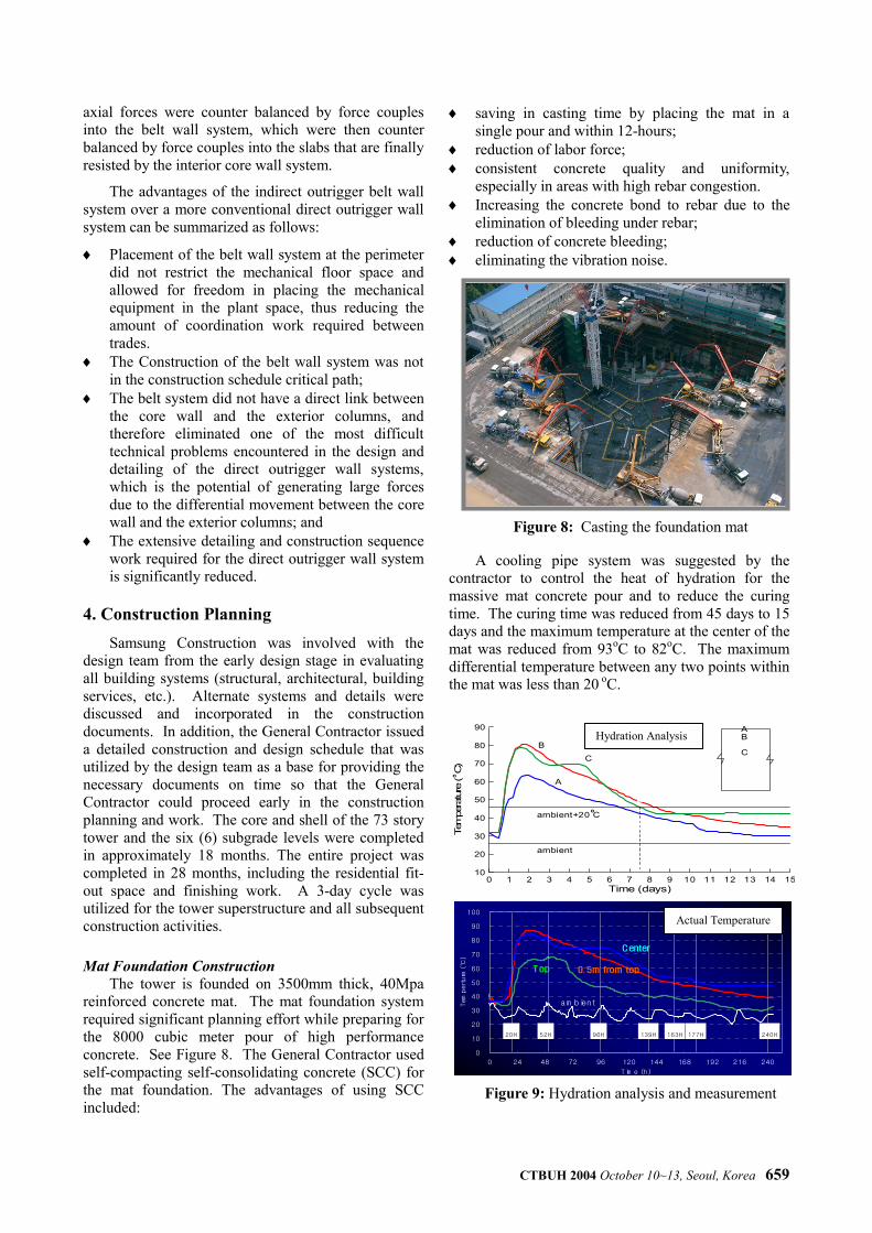
The tower is founded on 3500mm thick, 40Mpa reinforced concrete mat. The mat foundation system required significant planning effort while preparing for the 8000 cubic meter pour of high performance concrete. See Figure 8. The General Contractor used self-compacting self-consolidating concrete (SCC) for the mat foundation. The advantages of using SCC included:
♦ saving in casting time by placing the mat in a single pour and within 12-hours;
♦ reduction of labor force; ♦ consistent concrete quality and uniformity,
especially in areas with high rebar congestion. ♦ Increasing the concrete bond to rebar due to the
elimination of bleeding under rebar; ♦ reduction of concrete bleeding; ♦ eliminating the vibration noise.
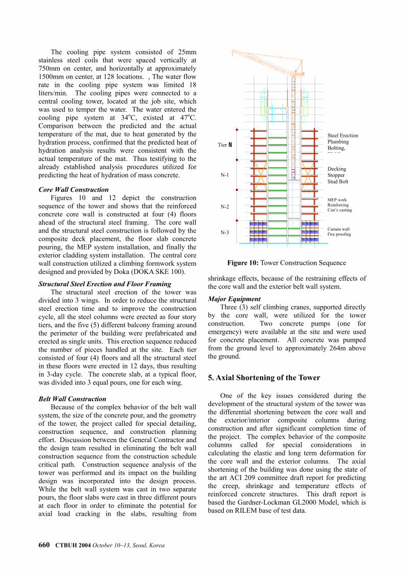
A cooling pipe system was suggested by the contractor to control the heat of hydration for the massive mat concrete pour and to reduce the curing time. The curing time was reduced from 45 days to 15 days and the maximum temperature at the center of the mat was reduced from 93oC to 82oC. The maximum differential temperature between any two points within the mat was less than 20 oC.
Figure 8: Casting the foundation mat
보 온 양 생 중 지
AB
C
0 1 2 3 4 5 6 7 8 9 10 11 12 13 14 15Time (days)
10
20
30
40
50
60
70
80
90
Tem
pera
ture
( C
)
B
ambient
o
ambient+20 C
C
A
o
0
10
20
30
40
50
60
70
80
90
100
0 24 48 72 96 120 144 168 192 216 240
Tim e (h)
Temperture (℃)
20H 52H 96H 139H 163H 177H 240H
Center
0. 5m from topTop
am bient
Hydration Analysis
Figure 9: Hydration analysis and measurement
Actual Temperature
660 CTBUH 2004 October 10~13, Seoul, Korea
The cooling pipe system consisted of 25mm stainless steel coils that were spaced vertically at 750mm on center, and horizontally at approximately 1500mm on center, at 128 locations. , The water flow rate in the cooling pipe system was limited 18 liters/min. The cooling pipes were connected to a central cooling tower, located at the job site, which was used to temper the water. The water entered the cooling pipe system at 34oC, existed at 47oC. Comparison between the predicted and the actual temperature of the mat, due to heat generated by the hydration process, confirmed that the predicted heat of hydration analysis results were consistent with the actual temperature of the mat. Thus testifying to the already established analysis procedures utilized for predicting the heat of hydration of mass concrete. Core Wall Construction
Figures 10 and 12 depict the construction sequence of the tower and shows that the reinforced concrete core wall is constructed at four (4) floors ahead of the structural steel framing. The core wall and the structural steel construction is followed by the composite deck placement, the floor slab concrete pouring, the MEP system installation, and finally the exterior cladding system installation. The central core wall construction utilized a climbing formwork system designed and provided by Doka (DOKA SKE 100).
Structural Steel Erection and Floor Framing The structural steel erection of the tower was
divided into 3 wings. In order to reduce the structural steel erection time and to improve the construction cycle, all the steel columns were erected as four story tiers, and the five (5) different balcony framing around the perimeter of the building were prefabricated and erected as single units. This erection sequence reduced the number of pieces handled at the site. Each tier consisted of four (4) floors and all the structural steel in these floors were erected in 12 days, thus resulting in 3-day cycle. The concrete slab, at a typical floor, was divided into 3 equal pours, one for each wing. Belt Wall Construction
Because of the complex behavior of the belt wall system, the size of the concrete pour, and the geometry of the tower, the project called for special detailing, construction sequence, and construction planning effort. Discussion between the General Contractor and the design team resulted in eliminating the belt wall construction sequence from the construction schedule critical path. Construction sequence analysis of the tower was performed and its impact on the building design was incorporated into the design process. While the belt wall system was cast in two separate pours, the floor slabs were cast in three different pours at each floor in order to eliminate the potential for axial load cracking in the slabs, resulting from
shrinkage effects, because of the restraining effects of the core wall and the exterior belt wall system.
Major Equipment Three (3) self climbing cranes, supported directly
by the core wall, were utilized for the tower construction. Two concrete pumps (one for emergency) were available at the site and were used for concrete placement. All concrete was pumped from the ground level to approximately 264m above the ground.
5. Axial Shortening of the Tower
One of the key issues considered during the development of the structural system of the tower was the differential shortening between the core wall and the exterior/interior composite columns during construction and after significant completion time of the project. The complex behavior of the composite columns called for special considerations in calculating the elastic and long term deformation for the core wall and the exterior columns. The axial shortening of the building was done using the state of the art ACI 209 committee draft report for predicting the creep, shrinkage and temperature effects of reinforced concrete structures. This draft report is based the Gardner-Lockman GL2000 Model, which is based on RILEM base of test data.
Steel ErectionPlumbing Bolting, W ldi
Decking Stopper Stud Bolt
MEP work Reinforcing Con’c casting
Curtain wall Fire proofing
Tier N
N-1
N-2
N-3
Figure 10: Tower Construction Sequence

CTBUH 2004 October 10~13, Seoul, Korea 661
The predicted composite columns and core wall axial shortening by the new analysis program were compared to the actual in-situ strain measurements at TPIII, and was found to correlate well, thus testifying to the accuracy of the new analysis models and approach in predicting the time dependent deformation for axially loaded members. See Figures 11 for comparison of the predicted strain to the actual measured strain.
A compensation program was developed to make up for the overall building shortening and the differential shortening between the columns and the core wall. The building shortening was calculated to be between 270mm to 300mm for the core wall and the exterior columns respectively. However, the maximum differential shortening, at level 60, between the columns and the core wall was estimated to be 40mm, at the completion of the building, and 20mm after 20 years. Therefore, the column elevations were adjusted during construction for 20mm so the relative movement between the core wall and the columns would be limited to a maximum of 20mm. The actual measured differential shortening between the core wall and the exterior columns have been found to be less than the predicted shortening.
At TPIII, several high frequency strain gages were installed at several SRC columns and at two locations in the core wall at several floors. These strain gages were connected to a single data logger from which the information has been down loaded automatically for processing by the researchers and the design team.
In addition to the in-situ elastic and inelastic time dependent deformation monitoring programs, a monitoring program has been installed to monitor the building dynamic response to dynamic excitations, especially as it relates to wind effects. It is anticipated that the instrumentation programs will be expanded and integrated into a single system that could essentially provides a health monitoring program to the building structure, which could finally be integrated with the permanent intelligent building system.
6. Conclusion
This paper provided a brief overview of some of the issues considered in developing the structural systems and construction planning of Tower Palace III, the tallest building in Korea. The monitoring programs incorporated into the design of the tower are very unique, could provide invaluable information and reference to the engineering community, and should be considered as part of the intelligent building system of important building in the world. Tower Palace III is a landmark tower for the city of Seoul.
Figure 11: Measured vs. predicted strains at a typical Interior composite column
Figure 12: Measured vs. predicted strain at reinforced concrete core wall
Figure 12: In progress construction of the tower showing the construction methods of the tower.