integration of electro-mechanical · pdf fileecad ecad pcb layout analysis – nx thermal...
TRANSCRIPT

Copyright © 2008 Siemens PLM Software, Inc. All Rights Reserved
Chang-kyu LeeME&S
Siemens PLM Software KR
Integration of electro-mechanical design

Copyright © 2008 Siemens PLM Software, Inc. All Rights Reserved
Pressure Deriving Electronics and Software into Products
Key Trends in Product Development

Copyright © 2008 Siemens PLM Software, Inc. All Rights Reserved
Electromechanical system designChallenges
Increased product complexity due to growth of electrical, electronics content and value in productsCoordinating separate disciplines, teams, processes, tools for electronic, electrical, control system and mechanical design
Integrating and coordinating product developmentManaging product variants/configurationManaging change
Globalization of supply chainsAccelerating development for shrinking product lifecycles

Copyright © 2008 Siemens PLM Software, Inc. All Rights Reserved
NX for Electromechanical Design/Simulation

Copyright © 2008 Siemens PLM Software, Inc. All Rights Reserved
NX for Electromechanical Design/Simulation
Unified system delivers seamless knowledge transfer
Synchronizes product and process knowledgeLeverages internal and external expertiseAllows cross functional teams to work together as one
Integration of electronic and mechanical design reduces rework by 50%
Process-based design applications increase user productivity
Styling Design
Electronic Design Simulation
Tooling Machining
Copyright © 2008 Siemens PLM Software, Inc. All Rights Reserved
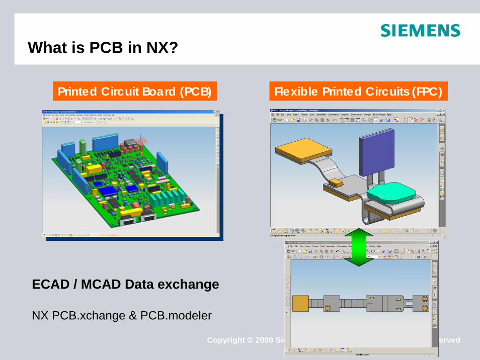
What is PCB in NX?
Printed Circuit Board (PCB) Flexible Printed Circuits (FPC)
ECAD / MCAD Data exchange
NX PCB.xchange & PCB.modeler

Copyright © 2008 Siemens PLM Software, Inc. All Rights Reserved
What are NX PCB.modeler & NX PCB.xchange?
PCB.modelerEmbedded into NX Defines components, board assembly, restriction areas, drilled holes…Validates the Printed Circuit Assemblies (PCA) and generates HTML reportsEnables assembly clearance checks, and other packaging tasks to be performed within an integrated environment
PCB.xchangeEmbedded into NX Application dedicated to associative data exchange with all ECAD systemsReads/writes IDF files (v.2, v.3, and v.4)Data filtering while writing NX or ECAD modelsGenerates detailed HTML reportsAssociative bi-directional exchange of PCB data with ECAD systems (the NX part is validated and changes are tracked and controlled within the NX native or Teamcenter managed environments)

Copyright © 2008 Siemens PLM Software, Inc. All Rights Reserved
Integrated Rigid/Flex PCB design and analysis
DetailedComponent
Placement and ECAD design
DetailedRouting
Detailed Board LevelThermal Analysis with
NX Thermal (NX4)
NX MCAD DesignECAD PCB Design NX Simulation
• Linear & Non-linear Structural Analysis
• Response Analysis• Thermal Fatigue•Creep
Data Interface toNX NASTRAN Structural
Analysis
System LevelThermo-fluid cooling Analysis with
NX ESC (NX5)or
Coupled NX Thermal & NX Flow (NX4)
Initial PCB Design and
PCB.modeler
Pre-place ConnectorsAnd Mechanical PartsWithin NX Assembly
Initial BoardProfile
Assembly Fit and Tolerance
Within NX Assembly
Initial Flexible PC Design and
PCB.modeler
Flattened Board
Flattened Board

Copyright © 2008 Siemens PLM Software, Inc. All Rights Reserved
Typical electromechanical design process (without Teamcenter)
Filter
IDF
IDF
Filter
ECAD
ECAD PCB Layout
Analysis – NX Thermal
Analysis – NX ESC
Bi-directionalassociativity

Copyright © 2008 Siemens PLM Software, Inc. All Rights Reserved
Managed electromechanical design process(with Teamcenter)
Teamcenter
IDFIDF
IDF
ECAD
ECAD PCB LayoutBi-directionalassociativity
Filter
Teamcenter
Filter
Filter
Standard component libraries(managed by Teamcenter)
Updated DesignPreliminaryMechanical
Layout
Electromechanical Simulation
Detailed Packaging

Copyright © 2008 Siemens PLM Software, Inc. All Rights Reserved
Working with existing ECAD Assemblies
IDF Standard support 3 LabelsTypically the primary identifier of a component part in EDA is its Part Number the MCAD user was to create a unique part for every electrical component number, versus a unique part for every component package (unique geometry) the MCAD component collection could be as much as 10 times larger
ECAD Label NX Terminology
Package Name (also called Geometry or Footprint Name) Part Name
Part Number Stored as PCB assembly component attribute
Reference Designator NX assembly component name

Copyright © 2008 Siemens PLM Software, Inc. All Rights Reserved
IDF Entity Support
Entity Type IDF 2.0 IDF 3.0 IDF 4.0
Panel Assembly Definitions & Instances O []Board Assembly Definitions & Instances [] []Panel Part Definitions & Instances O []Board Part Definitions & Instances [] []Component Part Definitions & Instances [] []3D Part Shapes with Cutouts & Cavities O []Holes (Mounting, Tooling, Pin, Via) O []Conductors (Pads, Traces, Filled Areas) []Routing & Placement Outlines [] []Keepouts (Routing, Trace, Via) [] []Graphics []Annotations O []Figures []Footprints []Sublayouts []Component Thermal Characteristics O []Board Design Variants []Miscellaneous Properties []Entity Owners O []

Copyright © 2008 Siemens PLM Software, Inc. All Rights Reserved
NX Electromechanical Systems DesignIntegrating electrical wiring and harness design
NX Electrical Routing Benefits
Fully integrated with NX design toolsEliminates redundant data re-creation, re-uses logical designAccurately predicts wire lengths and bundle diametersVerifies connections, enforces design standardsEliminates prototypes and rework

Copyright © 2008 Siemens PLM Software, Inc. All Rights Reserved
NX solutions for Electromechanical Simulation
YY- Stress PSD
RMS=19.7 MPa
Plastic Composites
Coupled Flow /Thermal
Flex Printed Circuits
Defense Systems
Vibration and Impact
Dust and Humidity
ECAD Integration
Knowledge ManagementDurabilityMulti-body DynamicsThermal Radiation
Electronics Systems Cooling

Copyright © 2008 Siemens PLM Software, Inc. All Rights Reserved
Demo
Copyright © 2008 Siemens PLM Software, Inc. All Rights Reserved
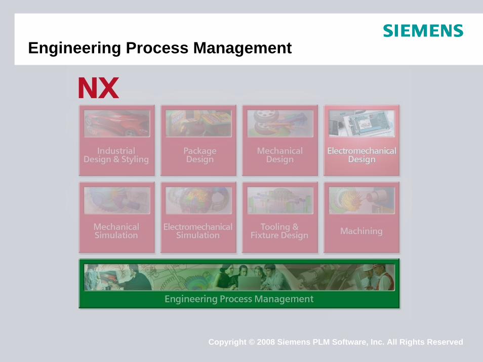
Engineering Process Management

Copyright © 2008 Siemens PLM Software, Inc. All Rights Reserved
Engineering Process ManagementSingle Source of Product & Process Knowledge

Copyright © 2008 Siemens PLM Software, Inc. All Rights Reserved
ElectronicsBoardstation
AllegroECAD Visualization
MechanicalNX, Solid Edge,
Catia, SolidWorks, Pro-E, Inventor
ClearCaseBinary Mgmt.
Software
NXAP21 & KBL
Open Interfaces
WH/Electrical
Engineering Process ManagementSingle Source of Product & Process Knowledge
Integrations with all major MCAD tools
Support for major ECAD tools
Wire Harness and Electrical support
Support for S/W source code and binary

Copyright © 2008 Siemens PLM Software, Inc. All Rights Reserved
Engineering Process ManagementSingle Source of Product & Process Knowledge

Copyright © 2008 Siemens PLM Software, Inc. All Rights Reserved
Electronic Design Integration
© 2007. Siemens Product Lifecycle Management Software Inc. All rights reservedSiemens PLM Software

Copyright © 2008 Siemens PLM Software, Inc. All Rights Reserved
Electronic Design Integration
Support for major schematic capture and board layout tools
CAD-centric integration BOM Extraction from PCB design PCB Data Stored in Teamcenter1. ECAD-native design archive2. Secondary data
• ECAD/MCAD interchange files (.idf)
• Assembly data archive• Visualization file

Copyright © 2008 Siemens PLM Software, Inc. All Rights Reserved
Electronic Design IntegrationDemo
Copyright © 2008 Siemens PLM Software, Inc. All Rights Reserved
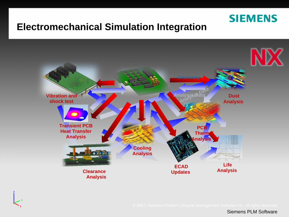
Electromechanical Simulation Integration
© 2007. Siemens Product Lifecycle Management Software Inc. All rights reservedSiemens PLM Software
Analysis Data
Geometry
Analysis Data Dust Analysis
Clearance Analysis
ECAD Updates
PCB Thermal
Analysis
Transient PCB Heat Transfer
Analysis
Vibration and shock test
Life Analysis
Cooling Analysis

Copyright © 2008 Siemens PLM Software, Inc. All Rights Reserved
CAE Items
24
CAEModelCAEMesh DS
Solver(number cruncher)
CAEResultCAESolution DS
CAD ItemUGMASTER DS
CAEGeometryCAEGeom DS
Bulk data deckNamed Reference
Binary output fileNamed Reference
CAEAnalysisCAESolution DS
Note: NX 6saves results underthe CAEAnalysis IR

Copyright © 2008 Siemens PLM Software, Inc. All Rights Reserved
CAE Item Relations
CAEModelCAEMesh DS
CAEResultCAESolution DS
CAD ItemUGMASTER DS
CAEGeometryCAEGeom DS
CAEAnalysisCAESolution DS
TC_CAE_ResultsTC_CAE_Defining
TC_CAE_Source
TC_CAE_Target
TC_CAE_Target
TC_CAE_Source

Copyright © 2008 Siemens PLM Software, Inc. All Rights Reserved
Relations Displayed on My TC Nav
Copyright © 2008 Siemens PLM Software, Inc. All Rights Reserved
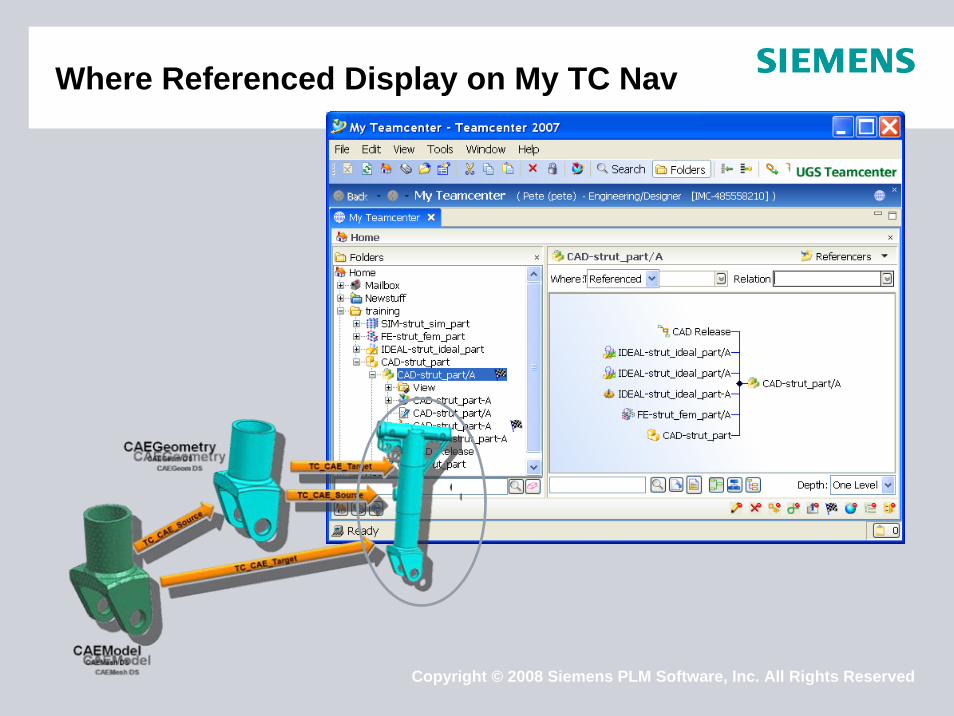
Where Referenced Display on My TC Nav

Copyright © 2008 Siemens PLM Software, Inc. All Rights Reserved
Electromechanical Simulation Integration Demo

Copyright © 2008 Siemens PLM Software, Inc. All Rights Reserved
Integration of electro-mechanical design –Summary
Integrated, single system solutionElecromechanical Integration
Flexible PCB designPCB.model & PCB.xchangeElectrical routingElectromechanical Simulation Mechatronics Process Management
Electronic Design IntegrationElectromechanical Simulation Integration
Single Source of Product & Process Knowledge

Copyright © 2008 Siemens PLM Software, Inc. All Rights Reserved© 2007. Siemens Product Lifecycle Management Software Inc. All rights reservedSiemens PLM Software
Thank You.Thank You.