integration of mirror design with suspension system using ... · integration of mirror design with...
TRANSCRIPT

Integration of mirror design with suspension system Using NASA’s new mirror modeling software
William R. Arnold, Sr*a, Ryan M. Bevanb, H. Phillip Stahlc
aDefense Acquisition, Inc., Jacobs ESSSA Group, Huntsville, AL, USA 35806; bNASA Intern, MSFC, Huntsville, AL, USA 35812; cNASA VP10, MSFC, Huntsville, AL, USA 35812
ABSTRACT
Advances in mirror fabrication are making very large space based telescopes possible. In many applications, only monolithic mirrors can meet the performance requirements. The existing and near-term planned heavy launch vehicles place a premium on lowest possible mass, and then available payload shroud sizes limit near term designs to 4 meter class mirrors. Practical 8 meter class and beyond designs could encourage planners to include larger shrouds, if it can be proven that such mirrors can be manufactured. These two factors, lower mass and larger mirrors, present the classic optimization problem. There is a practical upper limit to how large of a mirror can be supported by a purely kinematic mount system handling both operational and launch loads. This paper shows how the suspension system and mirror blank need to be designed simultaneously. We will also explore the concepts of auxiliary support systems which act only during launch and disengage on orbit. We will define required characteristics of these systems and show how they can substantially reduce the mirror mass.
Keywords: lightweight mirror design, modeling tools, AMTD example, suspension systems
1. INTRODUCTION
The AMTD project is developing and maturing the processes for future replacements for HUBBLE, JWST and beyond. It is doing this by creating the design tools, validating the methods and techniques necessary to manufacture, test and launch extremely large optical missions.
This paper intended to use the AMTD 4 meter “design point” as an illustration of how to use the modeler in generating the multiple models of mirror and suspension systems used during the conceptual design phase. The design point explored a range of hexapod geometry, mirror depth, cell size and construction techniques. The material and construction methods evaluated included Exelis Deep Core© Low Temperature Fusion, Corning Frit Bonded© and Schott Pocket Milled Zerodur©. Due to ITAR and proprietary constraints, actual AMTD results will not be included, only the modeling methods will be used to demonstrate the program’s range of capabilities for doing complex trade studies.
Basic premise of these trade studies is that you actually have to be able to make the design, as well as analytically show you can survive anticipated loads and weight limitations. This means that the construction techniques, the assembly/manufacturing process and optical “figuring” and testing needs have to be integrated into the blank design process. This integrated design methodology was very successfully applied to the Primary Mirror and suspension system for the Kepler Planet Finder Mission, indeed the predecessor program to this current modeler was used in that project at L3-Comm Integrated Optical Systems [designers and fabricators of that mirror system for Ball Aerospace].
1.1 Mirror Substrate Effects Design
Mirror substrate characteristics dictate potential construction methods. The three most common low expansion materials; ULE©, Zerodur© and Borosilicate or E6© each have characteristics which dictate which kind of light-weighting can be applied. ULE can be high temperature fused into larger assemblies of boules (which can be flowed out into thinner sheets) forming monolithic blanks, which can be further assembled into more complex assemblies. This material can be waterjet cut and pocket-milled, then two further assembly methods can be applied, “low temperature” fusion and “frit bonding”. Low temperature fusion usually requires optical contact (polished surfaces), which are normally flat surfaces
https://ntrs.nasa.gov/search.jsp?R=20140003101 2020-04-05T13:20:43+00:00Z
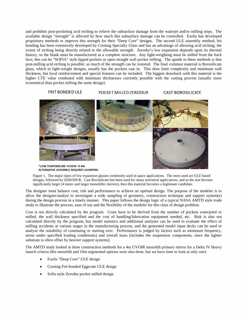
and prohibits post-pocketing acid etching to relieve the subsurface damage from the waterjet and/or milling steps. The available design “strength” is affected by how much this subsurface damage can be controlled. Exelis has developed proprietary methods to improve this strength for their “Deep Core” designs. The second ULE assembly method, frit bonding has been extensively developed by Corning Specialty Glass and has an advantage of allowing acid etching, the extent of etching being directly related to the allowable strength. Zerodur’s low expansion depends upon its thermal history, so the blank must be manufactured as a complete structure. Any light-weighting must be milled from the back face; this can be “SOFIA” style lipped pockets or open straight wall pocket milling. The upside to these methods is that post-milling acid etching is possible; so much of the strength can be restored. The final common material is Borosilicate glass, which in light-weight designs, usually has the pockets cast in. This does limit complexity and minimum wall thickness, but local reinforcement and special features can be included. The biggest drawback with this material is the higher CTE value combined with minimum thicknesses currently possible with the casting process (usually more economical than pocket milling the same design).
Figure 1. The major types of low expansion glasses commonly used in space applications. The most used are ULE based designs, followed by ZERODUR. Cast Borosilicate has been used for many terrestrial applications, and as the size become significantly larger (4 meter and larger monolithic mirrors), then this material becomes a legitimate candidate.
The designer must balance cost, risk and performance to achieve an optimal design. The purpose of the modeler is to allow the designer/analyst to investigate a wide sampling of geometry, construction technique and support system(s) during the design process in a timely manner. This paper follows the design logic of a typical NASA AMTD style trade study to illustrate the process, ease of use and the flexibility of the modeler for this class of design problem.
Cost is not directly calculated by the program. Costs have to be derived from the number of pockets waterjeted or milled, the wall thickness specified and the cost of handling/fabrication equipment needed, etc. Risk is also not calculated directly by the program, but model statistics and additional analyses can be used to evaluate the effect of milling accidents at various stages in the manufacturing process, and the generated model input decks can be used to analyze the suitability of continuing or starting over. Performance is judged by factors such as minimum frequency, stress under specified loading condition(s) and overall mass [includes the suspension components, since the lighter substrate is often offset by heavier support systems].
The AMTD study looked at three construction methods for a 4m UVOIR monolith primary mirror for a Delta IV Heavy launch criteria (8m monolith and 16m segmented options were also done, but we have time to look at only one):
• Exelis “Deep Core” ULE design
• Corning Frit-bonded Eggcrate ULE design
• Sofia style Zerodur pocket milled design.
2. QUICK INTRODUCTION TO MODELER
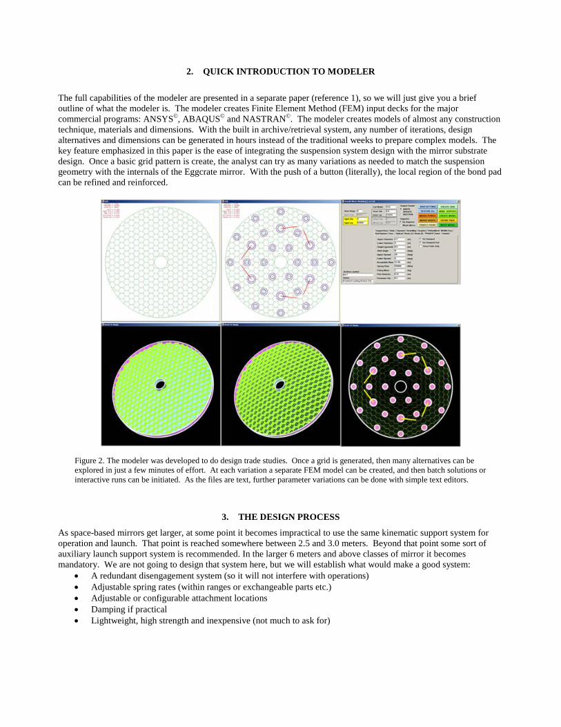
The full capabilities of the modeler are presented in a separate paper (reference 1), so we will just give you a brief outline of what the modeler is. The modeler creates Finite Element Method (FEM) input decks for the major commercial programs: ANSYS©, ABAQUS© and NASTRAN©. The modeler creates models of almost any construction technique, materials and dimensions. With the built in archive/retrieval system, any number of iterations, design alternatives and dimensions can be generated in hours instead of the traditional weeks to prepare complex models. The key feature emphasized in this paper is the ease of integrating the suspension system design with the mirror substrate design. Once a basic grid pattern is create, the analyst can try as many variations as needed to match the suspension geometry with the internals of the Eggcrate mirror. With the push of a button (literally), the local region of the bond pad can be refined and reinforced.
Figure 2. The modeler was developed to do design trade studies. Once a grid is generated, then many alternatives can be explored in just a few minutes of effort. At each variation a separate FEM model can be created, and then batch solutions or interactive runs can be initiated. As the files are text, further parameter variations can be done with simple text editors.
3. THE DESIGN PROCESS
As space-based mirrors get larger, at some point it becomes impractical to use the same kinematic support system for operation and launch. That point is reached somewhere between 2.5 and 3.0 meters. Beyond that point some sort of auxiliary launch support system is recommended. In the larger 6 meters and above classes of mirror it becomes mandatory. We are not going to design that system here, but we will establish what would make a good system:
• A redundant disengagement system (so it will not interfere with operations) • Adjustable spring rates (within ranges or exchangeable parts etc.) • Adjustable or configurable attachment locations • Damping if practical • Lightweight, high strength and inexpensive (not much to ask for)

The main design variables included front and back facesheet thickness (includes pocket milled isogrid patterns), core depth, core pocket geometry (hexagon span), core super-cell (segments fused at face and back only), core wall thicknesses. The second design variable set was the suspension system design, which consisted of standalone operational suspension and launch (classic hexapod design, both 3 pad and 6 pad versions) as well as the effectiveness of auxiliary launch supports. The balance between on-orbit performance (frequency, damping and stability) with the ability to carry launch loads (launch vehicle frequency interaction, stress in glass, etc) was included in the study. At the 4 meter mirror outer diameter, there is a debate wither the upper limit for which the use of a single system to perform both launch and operations functions has been exceeded. One of the main reasons for the trade study was to answer this question. As with any design effort, the values used are based upon the judgment of the analyst, not what a particular company claims they can produce or have even demonstrated at the subscale level. To avoid any ITAR or proprietary restrictions, the values shown do not represent the best that industry can achieve. As our basic example, we are looking at a minimum of 4 meters outer diameter. While some designs might still be possible without the use of auxiliary supports, we are going to include these in our process. We break the process into five distinct phases or steps:
1. Determine the most suitable material and construction method. Cost, schedule and risk associated with each, plus the normal mass and stiffness.
2. Determine mirror only performance (modes, weight and general sensitivities to depth, cell and thicknesses) 3. Determine the operational performance, initial mirror and operational suspension design(s). 4. Determine Mirror, operational and auxiliary system interaction (i.e. design auxiliary system) 5. Optimize Geometry, thicknesses, local reinforcement etc. Start evaluating manufacturing considerations such
as, facesheet flipping, assembly and polishing. 3.1 Step 1. Determine Best Material and Construction Method
Using the modeler without any FEM runs to determine the mirror substrate’s basic weight and volume distributions (how much in faceplates, core structure etc. are shown on the user interface as soon as you build the model). By adjusting thicknesses, depth and geometry (cell size, lip dimensions, etc.) you can quickly get feel for weight ranges and variable sensitivities. A push of a button and you have an input deck to run a modal case. The program also estimates the volume of pocket milling, surface areas and most of the information needed to put into cost models and risk models.
Figure 3. To get quick weight estimates for both cast borosilicate and milled Zerodur variations, the same grid mesh can be used. The options panel then allows either open back or pocketed design, with flat back aspheric or spherical back form.

Figure 4. Even the most complicated construction methods, such as the Excelsis Deep Core techniques can be modeled in a few minutes.
3.2 Step 2. Determine the mirror only performance
Once you have narrowed the material and style of the mirror down to one or two promising candidates, it is time to evaluate the mirror only design. The results generated during this step gives the designer a better understanding of how the geometry (cell size, lip dimensions, etc.) effects the frequency . Both the outer diameter and inner diameter are usual dictated by launch vehicle shroud dimensions and the mass goal is set by the launch vehicle lift-to-orbit capacity.
Figure 5. By changing a single parameter in the User Interface (UI) such as cell dimension and pushing three buttons you create a whole new model. At any point you can archive these settings to a named file for later restarts.

At this phase, the weight and first few bending modes of the mirror are the main objects of interest. With the same grid you can evaluate many combinations of faceplate pocketing and using simple text editor, the original input file can be modified (by changing real constants) the influence of plate thickness can be evaluated. All the element constants are fully commented in the generated input decks, so modifying these parameters is easily accomplished.
Figure 6. For any given grid (cell size) setting, the use of the options panel to select isogrid front or back or none can create separate models.
Figure 7. The combination of model statistics estimated by the program together with the modal only FEM runs gives the designer/analyst a good understanding of which dimensions and thicknesses have the most influence.
3.3 Step 3. Design the Operational Support System Together with the Mirror
At this phase, we are trying to match the geometry of the suspension system to the internal structure of the mirror. We are assuming a kinematic system, most likely a variant of the Hexapod (sometimes mistakenly called Bipod) system. There are two aspects of designing a hexapod system, geometry and stiffness. Figures 8 and 9 shown some of the matching problems often encountered. As you change cell size, the attachment points need to be adjusted as well. You have the freedom of a pad on a web intersection, centering over a cell or random position in relation to the internal structure (not recommended, but permitted). By varying the parameters on the hexapod panel, any possible system can be modeled. Once the geometry is where you want it, then you can iterate on spring rates. At this point local reinforcement in the region of each pad is available. With large cell sizes, or very light isogrid, the region around the pad can be substantially stiffened with minimal overall mass penalty. At this stage, you can also run a few launch loadcases.
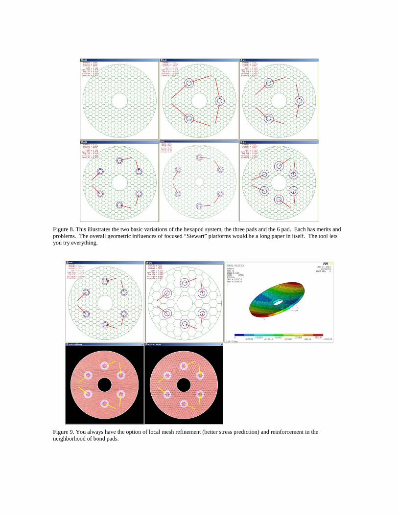
Figure 8. This illustrates the two basic variations of the hexapod system, the three pads and the 6 pad. Each has merits and problems. The overall geometric influences of focused “Stewart” platforms would be a long paper in itself. The tool lets you try everything.
Figure 9. You always have the option of local mesh refinement (better stress prediction) and reinforcement in the neighborhood of bond pads.
3.4 Step 4. Develop the Auxiliary Launch Support system.
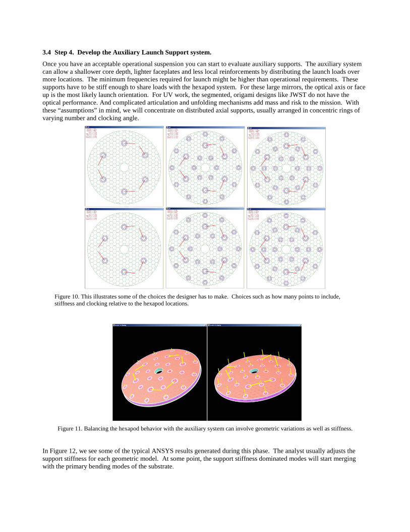
Once you have an acceptable operational suspension you can start to evaluate auxiliary supports. The auxiliary system can allow a shallower core depth, lighter faceplates and less local reinforcements by distributing the launch loads over more locations. The minimum frequencies required for launch might be higher than operational requirements. These supports have to be stiff enough to share loads with the hexapod system. For these large mirrors, the optical axis or face up is the most likely launch orientation. For UV work, the segmented, origami designs like JWST do not have the optical performance. And complicated articulation and unfolding mechanisms add mass and risk to the mission. With these “assumptions” in mind, we will concentrate on distributed axial supports, usually arranged in concentric rings of varying number and clocking angle.
Figure 10. This illustrates some of the choices the designer has to make. Choices such as how many points to include, stiffness and clocking relative to the hexapod locations.
Figure 11. Balancing the hexapod behavior with the auxiliary system can involve geometric variations as well as stiffness.
In Figure 12, we see some of the typical ANSYS results generated during this phase. The analyst usually adjusts the support stiffness for each geometric model. At some point, the support stiffness dominated modes will start merging with the primary bending modes of the substrate.

Figure 12. ANSYS results from first four phases (not all from same model parameters) just showing each stages.
3.5 Step 5. Refine the Design and Start Considering manufacturing Needs.
This is the stage where you start to refine pad sizes, make minor adjustments to thicknesses, reinforcement zones and start to see if design can be built. The modeler can take the settings and just create a faceplate model. Using the whiffle tree panel, you can see if a practical handling fixture can be made. At this point you can adjust the facesheet depths, rib structure and see the resulting mass changes. This is the time to find these things out.
Figure 13. Show some typical adjustments to pad size and how the internal structure influences this process.
4. SUMMARY AND CONCLUSIONS
The desire in the future of Space-based astronomy is larger Ultra-Violet Optical [UVO] telescopes. That implies monolithic light-weighted mirrors. As the aperture increases, traditional support systems will not suffice for both on orbit and launch conditions. We have introduced the concept of combining an auxiliary launch only support with the operational support system.
NASA’s new modeling tool was developed to make the design and optimization of the large and complex mirror systems practical and more robust. By substantially reducing the cost of multiple geometries and configurations, the design team can evaluate many more options, once impractical due to the time involved in generating large FEM models.
Experience has shown that an integrated design process, such as used in the Kepler Primary Mirror development produces a superior result. When features supporting all the manufacturing process, polishing, testing, handling and proof testing considerations are built into the mirror, you get minimum weight with low risk.
While this paper addressed space-based monolithic designs, the modeler is capable of dealing with multi-mirror (segmented) systems such as JWST (James Webb Space Telescope), and large (or small) terrestrial systems.
ACKNOWLEDGEMENTS
This work was performed under the JACOBS ESSSA contract NNM12AA41C at NASA MSFC in support of the Advanced Mirror Technology Development project which is funded by a NASA ROSES SAT (10-SAT10-0048). We would also like to thank the NASA Graduate Student Researcher Program and the NASA Intern Program for its support of this project.
REFERENCES
[1] Arnold, W. R., et al, "Next generation lightweight mirror modeling software," Proc. SPIE, 8836-15 (2013). [2] Arnold, W. R., “Kepler Photometer Primary Mirror Assembly Current Status,” NASA Tech Days (2004).