integration of sensor nodes with ims - diva
TRANSCRIPT

Master of Science ThesisStockholm, Sweden 2008
COS/CCS 2008-22
D A R W I N V A L D E R A S N Ú Ñ E Z
Integration of sensor nodes with IMS
K T H I n f o r m a t i o n a n d
C o m m u n i c a t i o n T e c h n o l o g y

Integration of sensor nodes
with IMS
Darwin Valderas Núñez [email protected]
Department of Communication Systems
School of Information and Communication Technology
Royal Institute of Technology (KTH)
Stockholm, Sweden
October 8, 2008
Supervisor and Examiner: Professor Gerald Q. Maguire Jr., PhD

i
To my parents, and brothers
ii
Abstract
The number of users adopting cellular system technologies over the past years has been
enormous. This rapid adoption is not comparable in any other technology. Additionally, this
has meant that these users have (at least some of the time) the possibility of connectivity to
others and to remote services (advanced data and voice services, such as video conferences,
mobile TV, navigation, and location services). Increasingly there is no longer a clear
boundary between the wide area cellular network and Internet services, as the wide area
cellular network is evolving from circuit switched based technologies to an IP based system;
hence these wide area cellular systems are simply becoming part of the Internet. This
evolution has become a challenge for the telecommunication operators, who have been used
to completely controlling their network services and billing. In an attempt to maintain this
traditional role for telecommunication operators, telecommunication vendors have introduced
the IP Multimedia Subsystem (IMS). A system designed to enable telecommunication
operators to be able to bill the user for all of the different services accessed through the wide
area cellular network. The goal of such a system is to prevent the telecommunication
operators from becoming a "bit pipe" (i.e., simply providing "commodity priced"
connectivity). Another relevant change that has direct impact upon this project is the role of
mobile handsets as gateways between sensor networks and other networks (especially the
wide area cellular networks or Internet). This has lead to integrated solutions, such as the
smart house concept, mobile health monitoring, and others.
This thesis project is a collaboration between Ericsson Research and SUUNTO, in which we
have implemented a system for monitoring a user’s heart rate via IMS. The system (has a
special focus on sports activities, but it could easily be adapted for health care) is based on
internetworking sensor networks, specifically a heart rate belt that transmits data wirelessly,
with the IMS network through a mobile phone or a PC. The implemented service runs on top
of the SIP Presence service. This project examines two alternatives. The first is a mobile
scenario, in which a person is jogging outdoors, in this setting the sensor node communicates
via the person’s mobile phone, through the IMS network to a monitoring application. The
second scenario is more fixed; such as a gym environment, where the sensor node
communicates with a personal computer which in turn publishes the data via IMS. Once the
data has been published to the Presence and group management sever, an application server
subscribed to the athlete’s Presence service will be notified. The people interested in viewing
this data will be able to see it through any web-browser. It will even be possible to archive,
and download the data for later use by other applications.
The system is not optimized yet for a truly real-time communication, as the Presence service
does not offer this as other technologies (RTP, SRTP or XMPP) do. There is a big delay
difference between the mobile and the fixed solution. We can say that the fixed solution is
almost a real-time system for transmitting low frequency data as heart rate information. This
project is a first approach to a final high performance system.

iii
Sammanfattning
Antalet användare som har fått tillgång till mobiltelefon under de senaste åren har varit
enorm. Detta snabbt antagande är inte jämförbar med någon annan teknik. Dessutom innebär
också detta att dessa användare har (åtminstone ibland) möjligheten till anslutning till andra
och till avlägsna tjänster (avancerad data-och taltjänster, t.ex. videokonferenser, mobil TV,
navigation och lokaliseringstjänster). Idags läget finns det inte längre en tydlig gräns mellan
cellulära nätet och Internettjänster. Efter cellulära nätets utveckling från kretskopplad teknik
till ett IP-baserat system, så håller dom cellulära systemem på att bli en del av Internet. Denna
utveckling har blivit en utmaning för telekommunikationsföretag, som har varit vana att helt
kontrollera sina nättjänster och fakturering. I ett försök att bevara denna traditionella roll för
telekommunikationsföretag, har telekom-leverantörer infört IP Multimedia Subsystem (IMS).
Ett system som syftar på att kunna göra telekommunikationsföretagen kapabla till att debitera
användaren för alla dem olika tjänsterna som han har tillgång till via deras cellulära nät. Målet
med ett sådant system är att förhindra telekommunikationsföretagen från att bli en "bit pipe"
(dvs bara ge prissatt konnektivitet). En annan betydelsefull förändring som har direkt inverkan
på detta projekt är den roll som mobiltelefoner kan utföra som gateways mellan sensornätverk
och cellulära nät eller Internet. Detta har påverkat flera integrerade lösningar, såsom smarta
hus begrepp, mobil hälsoövervakning och andra.
Denna examensarbetes projekt är ett samarbete mellan Ericsson Research och Suunto, där vi
har implementerat ett system för övervakning av en användares hjärtslag genom IMS.
Systemet (har en särskild inriktning på sport, men det kan lätt anpassas för hälso-och
sjukvård) är baserad på Internetworking sensornätverk, särskilt en hjärtfrekvens bälte som
överför data trådlöst till en mobiltelefon eller en dator, som sedan skickar ut datan via
IMS-nätverket. Tjänsten genomförs ovan på SIP Presence service. Projektet undersöker två
alternativ. Den första är en mobil scenario; exempelvis där en person joggar utomhus, vid ett
sådant tillfälle kommunicerar sensorn noden genom personens mobiltelefon, via IMS-nätverk
med en övervaknings application. Det andra scenariot är mer statiskt och ger inte samma
rörlighet, denna lösning passar bättre in på gym activiteter eller liknande. I denna
implementering kommunicerar sensorn noden med en persondator som i sin tur publicerar
uppgifterna via IMS. När uppgifterna har publicerats hos Presence and group management
(PGM) servern. En applikations server som är uppskriven på att få friidrottarens närvaro tjänst
kommer att meddelas. De människor som intresserade av att se denna data kommer att kunna
göra det via någon webbläsare. Det kommer även att vara möjligt att arkivera och hämta datan
för senare en användning men andra tillämpningar.
Systemet är inte optimerad ännu för en verkligt realtid, eftersom Presence service inte
erbjuder detta ännu som andra tekniker (RTP, SRTP eller XMPP) gör. Det finns en stor
fördröjning skillnad mellan den mobila och fasta lösningen. Vi kan säga att den fasta
lösningen är nästan ett realtids-system för överföring av lågfrekventa uppgifter som hjärtslag
information. Detta projekt är en första strategi för en slutlig högpresterande system.

iv
Acknowledgments
I would like to thanks Professor Gerald Maguire for all his great help and support. I want to
give my thanks to the people at Ericsson, especially Gonzalo Camarillo who gave me the
opportunity to work on this project, and for his continuous support at all levels. I would also
like to thanks Tomas Mecklin, Heidi-Maria Rissanen, Oscar Novo, and Miljenko Opsenica for
their help.
v
Contents
Abstract ............................................................................................................................................... II
List of figures .................................................................................................................................... IX
List of tables ........................................................................................................................................ X
Glossary .............................................................................................................................................. XI
1 Introduction .................................................................................................................................... 1
2 Background ..................................................................................................................................... 3
2.1 IP Multimedia Subsystem .................................................................................................................... 3
2.1.1 IMS Standardizations bodies ................................................................................................................. 3
2.1.2 IMS service overview ............................................................................................................................. 3
2.1.3 IMS architecture .................................................................................................................................... 5
2.2 Protocols used in IMS .......................................................................................................................... 9
2.2.1 Session Initiation Protocol (SIP) ............................................................................................................. 9
2.2.2 Session Description Protocol (SDP) ..................................................................................................... 13
2.2.3 Real-time Transport Protocol (RTP) ..................................................................................................... 13
2.2.4 Real-time Transport Control Protocol (RTCP) ...................................................................................... 14
2.2.5 The Secure Real-time Transport Protocol (SRTP) ................................................................................ 14
2.2.6 Diameter .............................................................................................................................................. 14
2.3 User identification ............................................................................................................................. 14
2.3.1 Private User identities ......................................................................................................................... 15
2.3.2 Public User Identities ........................................................................................................................... 15
2.3.3 Linking Private and Public User Identities ........................................................................................... 15
2.4 The SIM, USIM, and ISIM applications ............................................................................................... 16
2.4.1 SIM ....................................................................................................................................................... 16
2.4.2 USIM .................................................................................................................................................... 17
2.4.3 ISIM ...................................................................................................................................................... 17
2.5 Secure Access .................................................................................................................................... 17
2.5.1 Authentication and authorization ....................................................................................................... 17
2.5.2 Authentication and authorization with ISIM ....................................................................................... 18
2.5.3 The Generic Bootstrapping Architecture ............................................................................................. 19
2.6 IMS Registration ................................................................................................................................ 20
2.6.1 Registering with an ISIM ................................................................................................................... 20

vi
2.7 Real-time technologies: SIP, RTP and XMPP ...................................................................................... 24
2.7.1 Why SIMPLE? ........................................................................................................................................... 25
2.8 Overview of the Presence service ...................................................................................................... 25
2.8.1 Presence Subscriptions and Notifications ........................................................................................... 26
2.8.2 SUBSCRIBE Initial Request ................................................................................................................... 27
2.8.3 SUBSCRIBE Refresh request ................................................................................................................. 28
2.8.4 SUBSCRIBE Poll request ....................................................................................................................... 28
2.8.5 Watcher-side subscription termination ............................................................................................... 28
2.8.6 Server-side subscription termination .................................................................................................. 28
2.9 Presence Publication ......................................................................................................................... 29
2.9.1 PUBLISH Initial request ........................................................................................................................ 29
2.9.2 PUBLISH Refresh request ..................................................................................................................... 30
2.9.3 PUBLISH Modify request ...................................................................................................................... 30
2.9.4 PUBLISH Remove request .................................................................................................................... 30
2.10 The Presence service in the IMS ......................................................................................................... 31
2.10.1 Watcher Subscription ...................................................................................................................... 32
2.10.2 Presence publication ....................................................................................................................... 32
2.10.3 The Presence and Group Management (PGM) ............................................................................... 32
2.11 Sensor network ................................................................................................................................. 32
2.11.1 ANT .................................................................................................................................................. 34
2.11.2 Simple Sensor Interface (SSI) ........................................................................................................... 36
3 Related work................................................................................................................................ 42
3.1 Competing products .......................................................................................................................... 42
3.1.1 Nokia Eco Sensor Concept ................................................................................................................... 42
3.1.2 MiCoach ............................................................................................................................................... 42
3.1.3 Nike+iPod ............................................................................................................................................. 43
3.1.4 SDA-320 ............................................................................................................................................... 43
3.1.5 Comparative analysis ......................................................................................................................... 43
3.2 Body sensor networks and monitoring systems ................................................................................. 44
3.2.1 Efforts within the research community ............................................................................................... 44
3.2.2 Governmental efforts against CVD ...................................................................................................... 45
3.2.3 Heart Failure Management System ..................................................................................................... 46
3.3 Wireless body area sensor network ................................................................................................... 46
3.4 SensorPlanet...................................................................................................................................... 46
3.5 Urban sensing .................................................................................................................................... 47
4 System description: approach and methodology ....................................................... 48
4.1 System architecture ........................................................................................................................... 48
vii
4.2 Mobile solution ................................................................................................................................. 50
4.2.1 The mobile SPU’s signaling interaction................................................................................................ 50
4.2.2 Description of the mobile phone application ...................................................................................... 53
4.2.3 Execution on the MPA ......................................................................................................................... 54
4.2.4 Hardware used in the mobile SPU ....................................................................................................... 58
4.2.5 Tools used for developing the MPA ..................................................................................................... 58
4.3 Fixed solution .................................................................................................................................... 59
4.3.1 The fixed solution’s signaling interaction ............................................................................................ 59
4.3.2 Description of the Desktop application ............................................................................................... 60
4.3.3 Execution sequences of the desktop application ................................................................................ 62
4.3.4 Hardware used in the fixed SPU .......................................................................................................... 66
4.3.5 Tools used for developing the desktop application ............................................................................. 66
4.4 Watcher application .......................................................................................................................... 67
4.4.1 The Watcher application’s signaling interaction ................................................................................. 69
4.4.2 Description of the watcher application ............................................................................................... 70
4.4.3 Execution sequences of the watcher application ................................................................................ 71
4.4.4 Tools used for developing the watcher application ............................................................................ 73
5 Tests and discussion of the results ...................................................................................... 74
5.1 Functional tests ................................................................................................................................. 74
5.1.1 A PUA’s registration, subscription, and publishing process ................................................................ 74
5.1.2 A watcher subscribing to a presentity’s presence information ........................................................... 75
5.1.3 Adding a new watcher ......................................................................................................................... 77
5.1.4 Two watchers subscribing to the same HRM user’s presence information ........................................ 80
5.2 Performance tests ............................................................................................................................. 82
5.2.1 The SPU’s response time for HRM queries .............................................................................................. 83
5.2.2 End-to-end delay measurements ............................................................................................................ 84
5.2.3 Time period between consecutive messages received by the AS ....................................................... 86
Conclusions and future work .................................................................................................... 88
6.1 Conclusions ........................................................................................................................................ 88
6.1.1 General advantages and disadvantages .............................................................................................. 88
6.1.2 Mobile solution .................................................................................................................................... 88
6.1.3 Fixed solution ...................................................................................................................................... 89
6.1.4 Watcher application ............................................................................................................................ 89
6.2 Future work ....................................................................................................................................... 89
References ........................................................................................................................................ 90
Appendix A: functional testing logs ......................................................................................... 95
A.1 - A PUA’s registration, subscription, and publishing process .................................................................... 95

viii
A.2 - A watcher subscribing to a presentity’s presence information ............................................................... 99
A.3 - Adding a new watcher ......................................................................................................................... 102
A.4 - Two watchers subscribing to the same HRM user’s presence information ........................................... 106

ix
List of Figures FIGURE 1: IMS ARCHITECTURE ................................................................................................................................ 6
FIGURE 2: SIP SESSION SETUP ............................................................................................................................... 13
FIGURE 3: PUBLIC AND PRIVATE IDENTITIES PLUS USER....................................................................................... 16
FIGURE 4: AUTHENTICATION PROCESS. ................................................................................................................ 19
FIGURE 5: GENERIC BOOTSTRAPPING ARCHITECTURE ......................................................................................... 20
FIGURE 6: IMS REGISTRATION FLOW. ................................................................................................................... 22
FIGURE 7: PRESENCE NETWORK ELEMENTS. ........................................................................................................ 26
FIGURE 8: PRESENCE SUBSCRIPTIONS AND NOTIFICATIONS. ............................................................................... 27
FIGURE 9: PUBLISH REQUEST. ............................................................................................................................... 29
FIGURE 10: THE PRESENCE ENTITIES IN IMS. ........................................................................................................ 31
FIGURE 11: SENSOR NETWORK ELEMENTS. .......................................................................................................... 33
FIGURE 12: HEART RATE MONITOR, USB ANT TRANSCEIVER, AND ALL-IN-ONE MODULE. .................................. 34
FIGURE 13: OSI LAYER MODEL OF ANT. ................................................................................................................ 35
FIGURE 14: ANT SERIAL MESSAGE. ....................................................................................................................... 35
FIGURE 15: SSI UART PROTOCOL FRAME STRUCTURE. ......................................................................................... 37
FIGURE 16: SSI NETWORKING PROTOCOL, NANOUDP MESSAGE STRUCTURE. .................................................... 38
FIGURE 17: MESSAGE DIRECTION OF Q/Q AND A/A COMMANDS. ...................................................................... 39
FIGURE 18: ‘Q’ COMMAND MESSAGE (VALUES ARE SHOWN IN HEXADECIMAL). ................................................ 39
FIGURE 19: ‘A’ COMMAND MESSAGE. .................................................................................................................. 40
FIGURE 20: MESSAGE DIRECTION OF R/R AND V/V COMMANDS. ....................................................................... 40
FIGURE 21: ‘R’ COMMAND MESSAGE WITH MULTIPLE SENSOR IDENTIFIERS. ..................................................... 41
FIGURE 22: R COMMAND MESSAGE. .................................................................................................................... 41
FIGURE 23: ‘V’ COMMAND MESSAGE. .................................................................................................................. 41
FIGURE 24: SYSTEM ARCHITECTURE. .................................................................................................................... 49
FIGURE 25: SPU FOR MOBILE SOLUTION. ............................................................................................................. 50
FIGURE 26: THE MOBILE SPU’S GENERAL SIGNALING. .......................................................................................... 52
FIGURE 27: THE MPA MODULES. .......................................................................................................................... 53
FIGURE 28: GENERAL SEQUENCE DIAGRAM FOR THE MPA. ................................................................................. 55
FIGURE 29: EXECUTION OPTIONS MENU. ............................................................................................................. 56
FIGURE 30: LIST OF DEVICES. ................................................................................................................................ 56
FIGURE 31: HRM INFORMATION DISPLAYED ON A MOBILE PHONE. .................................................................... 57
FIGURE 32: SPU FOR FIXED SOLUTION. ................................................................................................................. 59
FIGURE 33: THE FIXED SPU’S GENERAL SIGNALING. ............................................................................................. 60
FIGURE 34: DESKTOP APPLICATION’S MODULE STRUCTURE 3 ............................................................................. 61
FIGURE 35: DESKTOP APPLICATION, ADDING USER OPERATION. ......................................................................... 62
FIGURE 36: DESKTOP APPLICATION, PUBLISHING MEASUREMENT INFORMATION. ............................................ 63
FIGURE 37: DESKTOP APPLICATION’S EXAMPLE SEQUENCE DIAGRAM. ............................................................... 64
FIGURE 38: USER CONTACTS IN WEB APPLICATION. ............................................................................................ 67
FIGURE 39: A CONTACT’S PRESENCE INFORMATION PAGE. ................................................................................. 68
FIGURE 40: STORED FILES TAB IN THE CONTACT’S PRESENCE INFORMATION PAGE. .......................................... 69
FIGURE 41: WATCHER APPLICATION’S SIGNALING INTERACTION. ....................................................................... 70
FIGURE 42: WATCHER APPLICATION MODULES ................................................................................................... 70
FIGURE 43: WATCHER APPLICATION GENERAL INTERACTION. ............................................................................. 72
FIGURE 44: REGISTRATION, SUBSCRIPTION, AND PUBLISH PROCESS. .................................................................. 75
FIGURE 45: FORMAT FOR SENDING THE HRM DATA. ........................................................................................... 75
x
FIGURE 46: WATCHER SUBSCRIBED TO PRESENCE INFORMATION. ..................................................................... 76
FIGURE 47: CREATING A NEW WATCHER APPLICATION USER. ............................................................................. 77
FIGURE 48: WATCHER APPLICATION’S LOGIN PAGE. ............................................................................................ 77
FIGURE 49: CONTACTS PAGE. ............................................................................................................................... 78
FIGURE 50: ADDING A NEW CONTACT. ................................................................................................................. 78
FIGURE 51: NEW CONTACT. .................................................................................................................................. 78
FIGURE 52: SIP SIGNALING FOR A NEW WATCHER. .............................................................................................. 79
FIGURE 53: NOTIFICATION FOR CHANGES IN A WATCHER LIST. ........................................................................... 80
FIGURE 54: TWO WATCHER’S SUBSCRIBING TO THE SAME PRESENTITY’S PRESENCE INFORMATION. ............... 81
FIGURE 55: PUA PUBLISHING HRM INFORMATION. ............................................................................................. 82
FIGURE 56: SPU RESPONSE TIME FOR HRM QUERIES – MOBILE SOLUTION. ........................................................ 83
FIGURE 57: SPU RESPONSE TIME FOR HRM QUERIES – FIXED SOLUTION. ........................................................... 84
FIGURE 58: END-TO-END DELAY – MOBILE SOLUTION. ........................................................................................ 85
FIGURE 59: END-TO-END DELAY – FIXED SOLUTION. ............................................................................................ 85
FIGURE 60: TIME BETWEEN TWO CONSECUTIVE MESSAGES RECEIVED IN THE AS – MOBILE SOLUTION. ........... 86
FIGURE 61: TIME BETWEEN TWO CONSECUTIVE MESSAGES RECEIVED IN THE AS – FIXED SOLUTION. .............. 87
List of Tables TABLE 1: SIP METHODS ......................................................................................................................................... 11
TABLE 2: RESPONSE CODES ................................................................................................................................... 12
TABLE 3: ANT SERIAL MESSAGE ............................................................................................................................ 36
TABLE 4: NANOIP MESSAGE STRUCTURE. ............................................................................................................. 38
TABLE 5: SSI COMMANDS. .................................................................................................................................... 39
xi
Glossary
3G Third generation
3GPP Third Generation Partnership Project
3GPP2 Third Generation Partnership Project 2
AAA Authentication, Authorization and Accounting
AKA Authentication and Key Agreement Protocol
ANSI American National Standards Institute
AS Application Server
AUTN Authentication Token
B2BUA Back to Back User Agent
BICC Bearer Independent Call Control
BGCF Breakout Gateway Control Function
BSF Bootstrapping Server Function
BSN Body Sensor Networks
CAMEL Customized Applications for Mobile network Enhanced Logic
CENS Center of Embedded Networked Sensing
CK Cipher Key
CN Core Network
CODEC Coder/Decoder
CSCF Call Session Control Function
CVD Cardio Vascular Diseases
ESP Encapsulating Security Payload
GBA Generic Bootstrapping Architecture
GGSN Gateway GPRS Support Node
GPRS General Packet Radio Service
GSM Global System for Mobile Communications
HFMS Heart Failure Management System
HLR Home Location Register
HRM Heart rate Monitor
HSS Home Subscriber Server
HTTP Hypertext Transport Protocol
IBCF Interconnection Border Control Function
I-CSCF Interrogating-Call Session Control Function
IDE Integrated Development Environment
IETF Internet Engineering Task Force

xii
IK Integrity Key
IM Instant Messaging
IMS IP Multimedia Subsystem
IMSI International Mobile Subscriber Identity
IM-SSF IP Multimedia Service Switching Function
IMS-MGW IP Multimedia Subsystem-Media Gateway
IPsec IP Security
ISIM IP Multimedia Subscriber Identity Module
ISUP ISDN User Part
ISWC International Symposium on Wearable Computers
LDAP Lightweight Directory Access Protocol
MAA Multimedia Authentication Answer
MAR Multimedia Authentication Request
MEGACO Media Gateway Control Protocol
MGCF Media Gateway Control Function
MPA Mobile Phone Application
MRF Media Resource Function
MRFC Media Resource Function Controller
MRFP Multimedia Resource Function Processors
MSC Mobile Switching Center
NAF Network Application Function
NAI Network Access Identifiers
OMA Open Mobile Alliance
OSA-SCS Open Service Access-Service Capability Server
PA Presence Agent
PC Personal Computer
P-CSCF Proxy-Call Session Control Function
PDA Personal Digital Assistant
PDF Policy Decision Function
PGM Presence and Group Management
PSTN Public switched telephone network
PUA Presence User Agent
QoS Quality of Service
RAND Random challenge
RLS Resource List Server
RTCP Real-Time Transport Control Protocol
RTP Real-time Transport Protocol

xiii
SAA Server Assignment Answer
SAR Server Assignment Request
S-CSCF Serving-Call Session Control Function
SDP Session Description Protocol
SGSN Serving GPRS Support Node
SGW Signaling Gateway
SIM Subscriber Identity Module
SLF Subscriber Location Function
SMTP Simple Mail Transport Protocol
SPP Serial Port Profile
SPU Signaling and Processing Unit
SQN Sequence number
SRTP Secure Real-time Transport Protocol
SSI Simple Sensor Interface
UA User agent
UAA User Authentication Answer
UAC User Agent Client
UAR User Authentication Request
UART Universal Asynchronous Receiver/Transmitter
UAS User Agent Server
UE User Equipment
UICC Universal Integrated Circuit Card
URI Uniform Resource Identifier
USIM Universal Subscriber Identity Module
VLR Visited Location Register
XCAP XML Configuration Access Protocol
XRES Expected Response
1
1 Introduction
The number of users of the cellular phone systems has increased very rapidly over the past
years. Today almost every person has accesses to mobile telephony services. In most of the
cases users have connectivity to others and to remote services (such as video conferencing,
mobile TV, navigation, and location-based services). Increasingly there is no longer a clear
boundary between the wide area cellular network and Internet services, as the wide area
cellular network is evolving from circuit switched based technologies to an IP based system;
hence these wide area cellular systems are simply becoming part of the Internet. This
evolution has become a challenge for the telecommunication operators, who have been used
to completely control their network services and billing. In an attempt to maintain this
traditional role for telecommunication operators, telecommunication vendors have introduced
the IP Multimedia Subsystem (IMS) (See chapter 2). A system designed for the
telecommunication operators to be able to bill the users for the different services accessed
through the wide area cellular network. The goal of such a system is to prevent the
telecommunication operators from becoming just a “bit pipe”.
Another relevant evolution, related to mobile phone systems is the role of mobile handsets as
gateways between sensor networks, and wide area cellular networks or Internet. This leads to
for example: integrated solutions, such as the smart house concept, mobile health monitoring,
and others. Body sensing and monitoring for health care has gathered the attention of both the
research community [4; 5] and governmental authorities [6], the interaction between these
body sensing networks and mobile phones is crucial for real-time monitoring of chronically ill
patients, it offers the health care provider the possibility of up to date information, then based
on this data they can provide feedback and guidance to the patient, in order to help the patient
in their daily life.
This thesis work project is a joint project between Ericsson Research (Lars Magnus Finland)
and SUUNTO. It explores the field of body sensing and monitoring (in a sports activity
context, but it could easily be adapted for health care). The objective is to sense a person’s
heart rate through a sensor chest belt that computes and transmits data wirelessly to a mobile
phone or a PC, where the data is processed and forwarded to a Presence and group management
(PGM) sever allocated in the IMS network, using the SIP Presence service publish mechanism.
The PGM in turn notifies an application server of each update. This application server can be
accessed from any web-browser, and the data can be viewed in a graphical form or
downloaded from the server to be used with other applications. Details of these technologies
will be presented in Chapter 2.
Two alternatives are examined. The first one is a mobile scenario, in which a person is doing
an outdoor sports activity that requires mobility, in this situation the sensor node
communicates via the person’s mobile phone, through the IMS network to the monitoring
application. The second scenario is meant to be used for indoor activities, in a scenario where
the user will have reduced mobility in terms of distance; such as a gym environment, where
2
the sensor node communicates wirelessly with a personal computer which in turn publishes
the data via IMS. Once the data is available via IMS, this solution is the same as the previous
solution. The software development related to this project has been done within the scope of
Ericsson Research’s HiFive [7] project, which is the first real IMS environment that is
publicly available for developers. This thesis work project is meant to be a proof of concept
application for the HiFive project.
When comparing this project with other products already existing in the market or with
known prototypes, we believe that within the field of athlete monitoring this is one of the
more advanced systems. However, there are systems for non-real-time monitoring that are far
more sophisticated. One of its major features is that it exploits the SIP Presence service for
data transfer which is standardized; this gives our service the potential to be easy integrated to
other presence aware services or applications. This solution exploits the concept of
community data sharing, making information available for other users. While sharing of data
is interesting and has been proposed (and done) by others - such as Runner+ [8], the real-time
communication of sensor data is very handy for closely monitoring an athlete. The systems
developed for health care vary widely and are normally more advanced when it come to the
sensor nodes. Additionally, they commonly use wearable sensors that are incorporated to the
user’s garment and often utilize multiple sensors in order to monitor several vital signs. Many
of these systems lack mobility, but there a few that are very highly integrated and offers full
mobility. A difference between these systems and ours is the chosen communication
technology. A discussion of these other systems will be given in Chapter 3.
This thesis project report is divided into 6 chapters; Chapter 1 is the introductory chapter.
Chapter 2 gives a background of the different technologies used for building the project’s
system. Chapter 3 shows the state of the art for body sensing and monitoring systems,
analyzing the commercially available products for physical training, environmental sensing,
and healthcare systems for patient monitoring. Chapter 4 describes the two implemented
solutions (fixed and mobile) for this system, going through the components, design,
functionalities, and methodology. In chapter 5 we make functionality and performance tests
over the system, after which we analysis of the results. Chapter 6 is the final chapter in this
thesis project report; here we go through the conclusions and possible future work.
3
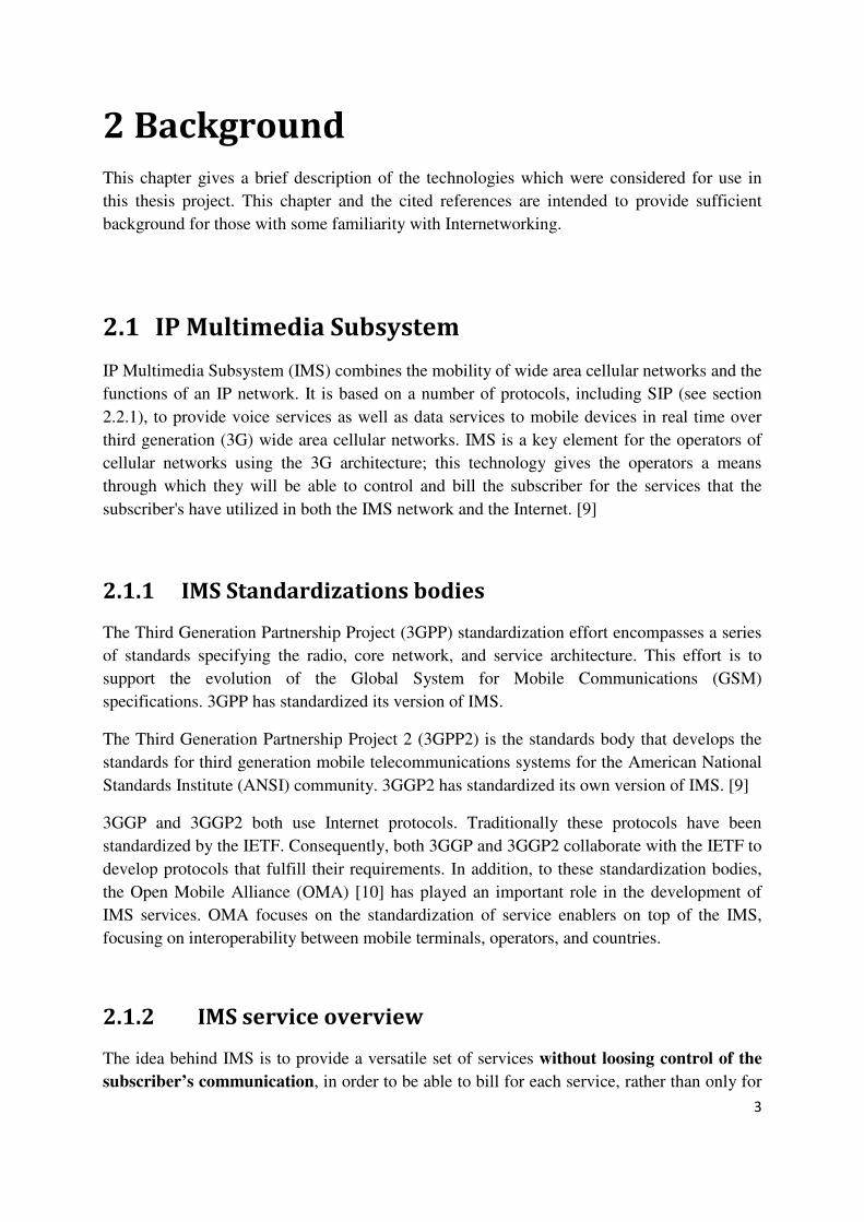
2 Background
This chapter gives a brief description of the technologies which were considered for use in
this thesis project. This chapter and the cited references are intended to provide sufficient
background for those with some familiarity with Internetworking.
2.1 IP Multimedia Subsystem
IP Multimedia Subsystem (IMS) combines the mobility of wide area cellular networks and the
functions of an IP network. It is based on a number of protocols, including SIP (see section
2.2.1), to provide voice services as well as data services to mobile devices in real time over
third generation (3G) wide area cellular networks. IMS is a key element for the operators of
cellular networks using the 3G architecture; this technology gives the operators a means
through which they will be able to control and bill the subscriber for the services that the
subscriber's have utilized in both the IMS network and the Internet. [9]
2.1.1 IMS Standardizations bodies
The Third Generation Partnership Project (3GPP) standardization effort encompasses a series
of standards specifying the radio, core network, and service architecture. This effort is to
support the evolution of the Global System for Mobile Communications (GSM)
specifications. 3GPP has standardized its version of IMS.
The Third Generation Partnership Project 2 (3GPP2) is the standards body that develops the
standards for third generation mobile telecommunications systems for the American National
Standards Institute (ANSI) community. 3GGP2 has standardized its own version of IMS. [9]
3GGP and 3GGP2 both use Internet protocols. Traditionally these protocols have been
standardized by the IETF. Consequently, both 3GGP and 3GGP2 collaborate with the IETF to
develop protocols that fulfill their requirements. In addition, to these standardization bodies,
the Open Mobile Alliance (OMA) [10] has played an important role in the development of
IMS services. OMA focuses on the standardization of service enablers on top of the IMS,
focusing on interoperability between mobile terminals, operators, and countries.
2.1.2 IMS service overview
The idea behind IMS is to provide a versatile set of services without loosing control of the
subscriber’s communication, in order to be able to bill for each service, rather than only for
4
the use of the communication medium. The hope of the telecommunication vendors and
operators is that new services will be quickly deployed due to the flexible architecture of IMS.
Operators in some countries have already deployed IMS services, Telefónica SA started to
implement IPTV over IMS in 2006 for their “Imagenio” IPTV service concept [11, 12]. By
the end of 2007 Com Hem released the first commercial IMS-platform for the Swedish
telecommunication market to support their VoIP services and next generation IP-telephony
[13]. Note that Com Hem's service is used on their cable TV network. Other services that are
being deployed using IMS are the following:
Telephony
services
IMS is expected to enhance current wireless and wired line telephony
technologies. For this reason, IMS provides common telephony services
such as call forwarding, call waiting, and call barring.
Presence Some applications will be presence-specific applications, such as a
phonebook showing presence information for all contacts and
presence-enhanced applications such as push-to-talk (which enables a user
to interact with a logical group of users who are all available at the same
time).
IMS messaging There are currently 3 forms of IMS messaging:
- Immediate messages or instant messages,
- Session-based messages, and
- Deferred delivery messages
Conferencing Conferencing is currently provided by many instant messaging
applications. Conferencing has mainly focused on video/audio
transmission and reception to emulate face to face conversations between
two or more parties. IMS utilizes the so called “tightly coupled
conference” approach; as defined in 3GPP’s technical specification
TS24.147 [14]. In tightly coupled conferences each party has a connection
to a central point (a conference bridge) that offers services such as media
mixing and participant list notifications.
5
Push-to-talk Push-to-talk is a service similar to walkie-talkie, as users are able to initiate
a voice transmission by simply pressing a button, and upon releasing the
button it ends. Unlike regular voice services push-to-talk is half duplex, it
simply means that a user transmits without having a return channel - it is
up to the receiver to decide how many such transmissions that they listen
to. A push-to-talk session can have more than two participants, but only
one can speak a time the rest are only listeners. Push-to-talk can run on top
of low bandwidth and high delay links, and it doesn’t require deployment
of new radio technologies. This service is already available in many
telecommunications operators network over the world, an example is [15].
Content sharing Content sharing allows users to immediately send multimedia content to a
certain contact. To make this kind of service more attractive, the services
are normally implemented together with presence services, thus users are
be able to see who is online and share video, audio, or image information
with their on-line contacts.
Some of the services presented in this section are currently under development, while others
services such as push-to-talk have been used for a period of time. What is important to
understand is that these services seek to take full advantage of the mobile device’s hardware,
so that customers can communicate in a greater variety of ways. [16]
Note: IMS is not essential to these services, since they can be implemented on top of SIP and
the Internet without using IMS. The services are likely to first appear in the Internet, as there
is a lower barrier to new service deployment in the Internet than in each vendor's IMS
network. Additionally, the lack of interworking between IMS networks is likely to delay the
wide spread adoption of services.
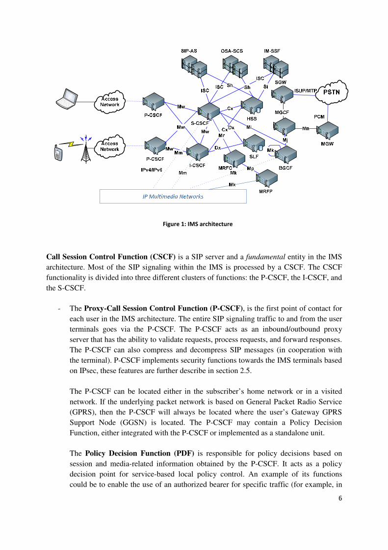
2.1.3 IMS architecture
In this section, the IMS entities and their key functionalities will be introduced. The 3GPP
standards do not describe how IMS entities interact; instead they define reference points
between entities and they define the functionality supported by each entity. [17] All the
functions and reference points to be mentioned in this section can be observed in figure 1.
6
Figure 1: IMS architecture
Call Session Control Function (CSCF) is a SIP server and a fundamental entity in the IMS
architecture. Most of the SIP signaling within the IMS is processed by a CSCF. The CSCF
functionality is divided into three different clusters of functions: the P-CSCF, the I-CSCF, and
the S-CSCF.
- The Proxy-Call Session Control Function (P-CSCF), is the first point of contact for
each user in the IMS architecture. The entire SIP signaling traffic to and from the user
terminals goes via the P-CSCF. The P-CSCF acts as an inbound/outbound proxy
server that has the ability to validate requests, process requests, and forward responses.
The P-CSCF can also compress and decompress SIP messages (in cooperation with
the terminal). P-CSCF implements security functions towards the IMS terminals based
on IPsec, these features are further describe in section 2.5.
The P-CSCF can be located either in the subscriber’s home network or in a visited
network. If the underlying packet network is based on General Packet Radio Service
(GPRS), then the P-CSCF will always be located where the user’s Gateway GPRS
Support Node (GGSN) is located. The P-CSCF may contain a Policy Decision
Function, either integrated with the P-CSCF or implemented as a standalone unit.
The Policy Decision Function (PDF) is responsible for policy decisions based on
session and media-related information obtained by the P-CSCF. It acts as a policy
decision point for service-based local policy control. An example of its functions
could be to enable the use of an authorized bearer for specific traffic (for example, in

7
order to implement better than best effort service - of course this would entail higher
charges).
- The Interrogating-Call Session Control Function (I-CSCF) is a SIP server that
provides an entry point to an operator’s IMS network. In an operator's network there
may be multiple I-CSCFs. The I-CSCF address can be listed as an external address of
an IMS network in DNS domain records for this IMS operator's domain. The I-CSCF
is involved in the registration process as it assigns a S-CSCF to a user when
performing SIP registration. The I-CSCF also takes part in session-related and
session-unrelated flows, for example when obtaining the address of the S-CSCF from
Home Subscriber Server (HSS) or when routing SIP requests received from another
networks towards the responsible S-CSCF. The I-CSCF can be involved in charging
for resource utilization by generating appropriate call data records.
Note: If border control is applied, then the contact point for an operator's network may be
different, this is explained below.
- The Serving-Call Session Control Function (S-CSCF), is the core of IMS; it
provides the logic to invoke and manage the application servers as needed to deliver
the requested services. This entity is located in the subscriber's home network, it
interacts with the HSS in order to determine the subscriber's service eligibility by
downloading the subscriber's user profile, it also provides session control and
registration services for User Equipment (UE), i.e., terminals/handsets. It maintains a
mapping between the user agent's location (IP address of the user terminal) and the
user’s SIP URI, for further details see [9].
The Interconnection Border Control Function (IBCF) may be applied between two IP
Multimedia core network (CN) subsystems or between an IP Multimedia CN subsystem and
other SIP based multimedia networks. If IBCF is implemented in an IMS network, it will acts
as an entry point for this network (instead of the I-CSCF), and it will also be the exit point of
this network. An IBCF can provide the following functions:
- Control of transport plane functions.
- Supports functions that allow establishing communication between IP Multimedia CN
subsystems using different media CODECs based on the interworking agreement and
session information.
- Network configuration hiding to restrict information from being passed outside of an
operator's network, such as: number of S-CSCFs, capabilities of S-CSCFs, or capacity
of the network.
8
- Screening of the SIP signalling information based on source/destination and operator
policy (e.g. remove information that is of local significance to an operator).
- Generation of Call Data Records.
- Invocation of an interworking function in operations between different SIP profiles or
different protocols (e.g., SIP and H.323) is necessary; in this case the interworking
function acts as an entry point for the IMS network;
Note: The IBCF and I-CSCF may be co-located as a single physical node. Network
configuration hiding was not intended to be invoked in IMS roaming scenarios when the
P-CSCF and IBCF are both located in the visited network. The interworking function is not
specified within the latest release [18] of the specification.
An Application server (AS) is a SIP entity that hosts and implements services. It will operate
in different modes depending on the service. For example, it could operate as a SIP proxy,
User agent (UA), or back-to-back user agent (B2BUA). An AS is built upon three different
types of functions:
- SIP AS (the native AS) hosts and implements SIP based IMS services.
- Open Service Access-Service Capability Server (OSA-SCS) acts as an interface to
the Open Service Access (OSA) framework. It provides secure access to IMS from
visited networks.
- IP Multimedia Service Switching Function (IM-SSF), with this AS an operator is
able to offer access to services based on the Customized Applications for Mobile
network Enhanced Logic (CAMEL) Service Environment. This is further described in
[19].
An AS can reside in the home network or in a visited network. However, if the AS is located
in a visited network, it will not have an interface to the subscriber's HSS.
The Home Subscriber Server (HSS) is a secure database. It stores the subscriber's user
profile information, provides identity management, and user status (both presence and
location(s)). This information is predominantly accessed by the S-CSCF for validation of the
subscriber and to determine authorized service capabilities. The I-CSCF and the application
servers also have access to the HSS database. The HSS is an evolution of the Home Location
Register (HLR). If there are several HSSs in a domain, a Subscriber Location Function (SLF)
is required. The SLF is simply a database that indicates in which HSS a subscriber's user
profile is located. This is further described in [9].

9
Note: The remaining IMS functions are not of relevance for this thesis project, but if the
reader is interested, more detailed information can be found in [9].
2.2 Protocols used in IMS
3GPP has adopted a number of different protocols, each with their specific usage and
functionality for IMS. The most relevant protocols for this thesis work will be mentioned
below.
2.2.1 Session Initiation Protocol (SIP)
The SIP protocol’s latest specification is contained in the Internet Engineering Task Force
(IETF) SIP Working Group’s RFC 3261 [20]. SIP is a text-encoded protocol based on
elements from the Hypertext Transport Protocol (HTTP) and the Simple Mail Transport
Protocol (SMTP). SIP’s main purpose is to manage sessions, specifically to establish, modify,
and terminate multimedia sessions. An example of a session would be an Internet telephony
call. SIP can also be used to invite participants to existing sessions, such as conferences.
Media streams can be added or removed from an existing session; this media can be audio,
video, text, etc. SIP transparently supports name mapping and redirection services, these
features enable user mobility. Therefore users can maintain a single visible identifier
regardless of their network location. A typical SIP system is based upon three main elements:
SIP User Agents, SIP servers, and location servers. For detailed information the reader is
encouraged to read the latest SIP RFC [20], as updated by RFC 3853[21] and RFC 4320 [22].
SIP Network elements
User Agents (UA) are the end components in a SIP network. They make SIP requests to
establish media sessions; they may also send and receive media. A UA can be a SIP phone or
SIP client software installed on a PC or other system. UAs generally contain both a client and
a server part. The UA client (UAC) generates SIP requests, while the UA server (UAS)
responses to received SIP requests.
SIP servers are SIP intermediaries that are located within a SIP network (i.e., the network of
devices which understand SIP). These servers assist the UAs in session establishment and in
other functions (such as routing of SIP requests and responses). SIP servers can be divided
into Proxy servers, Redirect servers, and Registrar servers.
- Proxy servers receive SIP requests from UAs or other proxies and forwards or proxy
the request to another destination. A proxy server can also authenticate and authorize
users for services, implement provider call-routing policies, and assist users with

10
features that will control the behavior of the proxy for subsequent sessions (for
example, defining what is to be done with calls from a certain source, defining what is
to be done with calls at different times or the day or on different days, etc.).
- Redirect servers send routing information back in response to a client’s request,
thereby redirecting further messages related to this request (for example, when a user's
proxy has moved to a new location because the callee has changed SIP provider).
When the originator of the request receives the redirect, it will send a new request to a
different address, based on the Uniform Resource Identifier (URI) it has received from
the redirect server.
- Registrar servers receive SIP registration requests from a UA and update the user's
location information (by storing the new location at a location server), this information
is used by the proxy servers when they wish to locate the user's current user agent(s).
SIP proxies, redirect, and registrar servers are purely logical SIP elements. They have no
media capabilities and do not initiate requests - except on behalf of UAs. They can be
implemented in one machine or replicated over many nodes (for increased reliability,
availability, and capacity).
Location servers are not SIP entities, but they are an important part of a SIP network’s
architecture. A location server stores, and returns the location(s) of the user's user agent(s)
when queried by a SIP server. The location server can make use of information from
registrars or other databases. Most registrars upload location updates to a location server upon
reception of new location information. The location server's database may store information
about the user's user agent(s) such as their URIs, IP addresses, features, and other information.
It may also contain routing information.
UAs do not interact directly with the location server, but rather do so via a registrar server.
SIP servers use a non-SIP protocol to query, update, and retrieve records from the location
servers (some servers uses the Lightweight Directory Access Protocol (LDAP) [23]).
SIP Request
The standard SIP implementation implements 6 different methods, but there are several
extensions to the standard that have been implemented over the years, adding features
enabling richer communication capabilities (e.g., Presence services and Instant messaging
(IM)). SIP requests consist of headers and a message body. The standard SIP methods are
shown in table 1.
11
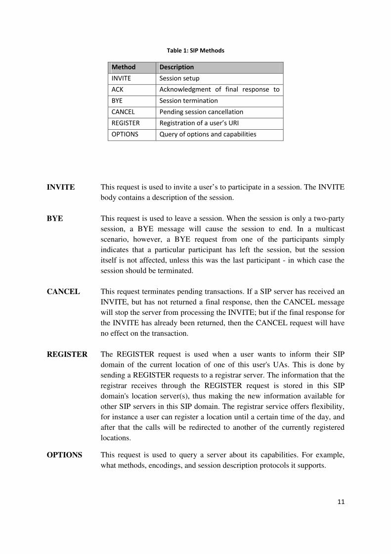
Table 1: SIP Methods
Method Description
INVITE Session setup
ACK Acknowledgment of final response to
INVITE BYE Session termination
CANCEL Pending session cancellation
REGISTER Registration of a user’s URI
OPTIONS Query of options and capabilities
INVITE This request is used to invite a user’s to participate in a session. The INVITE
body contains a description of the session.
BYE This request is used to leave a session. When the session is only a two-party
session, a BYE message will cause the session to end. In a multicast
scenario, however, a BYE request from one of the participants simply
indicates that a particular participant has left the session, but the session
itself is not affected, unless this was the last participant - in which case the
session should be terminated.
CANCEL This request terminates pending transactions. If a SIP server has received an
INVITE, but has not returned a final response, then the CANCEL message
will stop the server from processing the INVITE; but if the final response for
the INVITE has already been returned, then the CANCEL request will have
no effect on the transaction.
REGISTER The REGISTER request is used when a user wants to inform their SIP
domain of the current location of one of this user's UAs. This is done by
sending a REGISTER requests to a registrar server. The information that the
registrar receives through the REGISTER request is stored in this SIP
domain's location server(s), thus making the new information available for
other SIP servers in this SIP domain. The registrar service offers flexibility,
for instance a user can register a location until a certain time of the day, and
after that the calls will be redirected to another of the currently registered
locations.
OPTIONS This request is used to query a server about its capabilities. For example,
what methods, encodings, and session description protocols it supports.
12
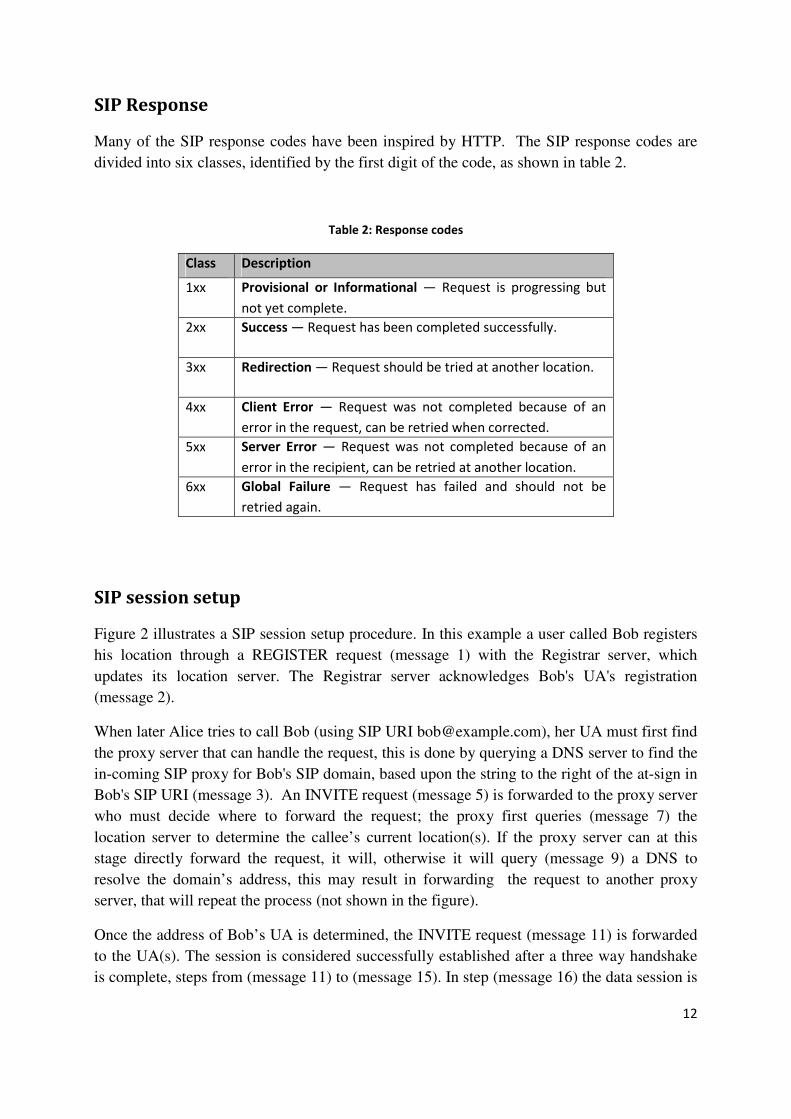
SIP Response
Many of the SIP response codes have been inspired by HTTP. The SIP response codes are
divided into six classes, identified by the first digit of the code, as shown in table 2.
Table 2: Response codes
Class Description
1xx Provisional or Informational — Request is progressing but
not yet complete.
2xx Success — Request has been completed successfully.
3xx Redirection — Request should be tried at another location.
4xx Client Error — Request was not completed because of an
error in the request, can be retried when corrected.
5xx
Server Error — Request was not completed because of an
error in the recipient, can be retried at another location.
6xx Global Failure — Request has failed and should not be
retried again.
SIP session setup
Figure 2 illustrates a SIP session setup procedure. In this example a user called Bob registers
his location through a REGISTER request (message 1) with the Registrar server, which
updates its location server. The Registrar server acknowledges Bob's UA's registration
(message 2).
When later Alice tries to call Bob (using SIP URI [email protected]), her UA must first find
the proxy server that can handle the request, this is done by querying a DNS server to find the
in-coming SIP proxy for Bob's SIP domain, based upon the string to the right of the at-sign in
Bob's SIP URI (message 3). An INVITE request (message 5) is forwarded to the proxy server
who must decide where to forward the request; the proxy first queries (message 7) the
location server to determine the callee’s current location(s). If the proxy server can at this
stage directly forward the request, it will, otherwise it will query (message 9) a DNS to
resolve the domain’s address, this may result in forwarding the request to another proxy
server, that will repeat the process (not shown in the figure).
Once the address of Bob’s UA is determined, the INVITE request (message 11) is forwarded
to the UA(s). The session is considered successfully established after a three way handshake
is complete, steps from (message 11) to (message 15). In step (message 16) the data session is

13
initiated directly between Alice's UA and Bob's UA (probably using RTP or SRTP –
mentioned in sections 2.2.3 and 2.2.5).
Figure 2: SIP session setup
Note: Messages 7 and 8 are not SIP messages (they could be an LDAP query and response).
Similarly the DNS queries and responses of messages 3, 4, 9, and 10 are not SIP messages.
2.2.2 Session Description Protocol (SDP)
The SDP protocol was defined by the IETF in RFC 4566 [24]. SDP is purely a format for
session description. A session description could include information such as the purpose of
the session, the media and the codec’s used in the session. SDP can use various transport
protocols among them SIP. SDP is not intended to support negotiation of session content or
media encoding. [24]
2.2.3 Real-time Transport Protocol (RTP)
IMS utilizes RTP for media sessions. This protocol was developed by the IETF and defined in
RFC 3550 [25]. RTP was primarily designed to satisfy the needs of multi-participant
multimedia conferencing, but today it is used for many different types of applications. RTP
provides end-to-end delivery services for data with real-time characteristics, such as audio and
video. RTP typically runs on top of UDP, no specific ports are defined for this purpose, but
rather an even port and the next higher odd port are used (the later is used by the Real-time
Transport Control Protocol (RTCP) to provide feedback on the RTP transported data). RTP

14
does not provide any Quality of Service (QoS) guarantees at all. However, it does allow
transmission imperfections such as packet loss or jitter to be detected with the help of the
sequence numbers and time stamps in the RTP packets and the sender and receiver reports
sent in RTCP. [25]
2.2.4 Real-time Transport Control Protocol (RTCP)
RTCP was defined by the IETF in RFC 3550 [24]. The primary function of this protocol is to provide information to monitor the quality of service for RTP flows. This information includes the number of bytes sent, packets sent, lost packets, jitter, and round trip delay. RTCP also transmits control packets to participants in a multimedia streaming session, so that the participants can learn who the other participants are. An application may use RTCP information to increase the quality of service perhaps by limiting flow, switching to a low compression coder-decoder (CODEC) instead of a high compression CODEC, turning off specific types of media (for example, turning off video), etc. For a description of this see [26]. There are several types of RTCP packets: Sender report packet, Receiver report packet,
Source Description RTCP Packet, Goodbye RTCP Packet, and Application Specific RTCP
packets as defined in RFC 3550 [25].
2.2.5 The Secure Real-time Transport Protocol (SRTP)
The secure real-time transport protocol (SRTP) was defined by the IETF in RFC 3711 [27].
SRTP is a profile of RTP. It can provide confidentiality, message authentication, and replay
protection to the RTP traffic and to RTCP. For further details see [28].
2.2.6 Diameter
The 3GPP standards body has adopted Diameter as the primary signaling protocol for
authentication, authorization, and accounting (AAA) in IMS. Diameter was developed and
standardized by IETF as described in RFC 3588 [29]. Diameter is used by IMS’s SIP servers
(CSCFs) to perform authentication using information provided by the HSS and to determine if
a client is authorized to access the services provided by the server.
2.3 User identification
In IMS the system’s users and terminals need to be identified, as well as authenticated. Users
have the option to have different identity profiles according to the service they wish to use.
These identities are to two types: public and private.

15
2.3.1 Private User identities
A private user Identity is a globally unique identifier assigned by the subscriber's home
network operator. Because private identities do not actually reveal the user's identity, but
rather the user’s subscription, they can be used for tasks such as administration, accounting,
authorization, and registration. However, these private user identities are mainly used for
authentication purposes. [16, 18]
Private user identities resemble email addresses, in the sense that they act as a Network
Access Identifiers (NAI). [30] That is, a portion of the identity is a name given to the user and
the other portion identifies the domain or network it belongs to. An example of a private user
identity is username@operatordomain. This identity is permanently allocated by the home
network to a user’s subscription. The Private User Identity performs a similar function in the
IMS as an International Mobile Subscriber Identifier (IMSI) does in GSM. This identity is
valid as long as the user’s subscription to the home network is applicable. [18]
2.3.2 Public User Identities
Public User Identities are the identities used by external entities to interact with the IMS
network. These identities are public to the network and may be published in phone books, on
business cards, etc. [16]. Public User Identities may take the form of a SIP URI
(sip:name.surname@domain) or a TEL URI (tel:+1234567). These two forms are necessary
for interworking between different networks such the Internet and GSM. [18] TEL URIs are
needed when interworking with the PSTN. A Public User Identity plays a role in IMS similar
to a Mobile Subscriber ISDN Number in GSM.
2.3.3 Linking Private and Public User Identities
Public and private user identities are related to each other. A user can have more than one
public identity and use each of these identities for different services. In IMS, each public
identity can establish a different treatment for incoming sessions. [16] Moreover, a user may
use a certain identity for one service and merge the remaining identities for another type of
service. IMS user profiles allow a user to have a set of identities for a service and each
identity is treated differently within the service used. Figure 3 shows a graphical presentation
of the relationship between public and private identities.
16
Public User Id
entitie
s
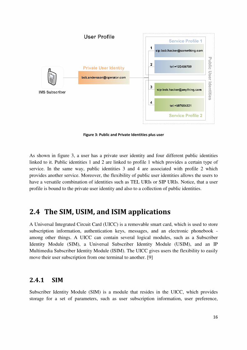
Figure 3: Public and Private Identities plus user
As shown in figure 3, a user has a private user identity and four different public identities
linked to it. Public identities 1 and 2 are linked to profile 1 which provides a certain type of
service. In the same way, public identities 3 and 4 are associated with profile 2 which
provides another service. Moreover, the flexibility of public user identities allows the users to
have a versatile combination of identities such as TEL URIs or SIP URIs. Notice, that a user
profile is bound to the private user identity and also to a collection of public identities.
2.4 The SIM, USIM, and ISIM applications
A Universal Integrated Circuit Card (UICC) is a removable smart card, which is used to store
subscription information, authentication keys, messages, and an electronic phonebook -
among other things. A UICC can contain several logical modules, such as a Subscriber
Identity Module (SIM), a Universal Subscriber Identity Module (USIM), and an IP
Multimedia Subscriber Identity Module (ISIM). The UICC gives users the flexibility to easily
move their user subscription from one terminal to another. [9]
2.4.1 SIM
Subscriber Identity Module (SIM) is a module that resides in the UICC, which provides
storage for a set of parameters, such as user subscription information, user preference,

17
authentication keys, and storage of messages, that are used for the operation of terminals in a
GSM network.
2.4.2 USIM
A Universal Subscriber Identity Module (USIM) is a module that resides in the third
generation UICCs used to access UMTS networks. There are terminals capable of operating
with both SIM and USIM, i.e., to operate in GSM and UMTS networks. A USIM provides
information similar in nature that provided by a SIM: user subscriber information,
authentication information, payment methods, and message storage. More detailed
information about the USIM can be found in [31].
2.4.3 ISIM
IP Multimedia Subscriber Identity Module (ISIM) is a third module that can be implemented
in the UICC. The ISIM contains a set of parameters that are used for user identification, user
authentication, and terminal configuration when operating over IMS. ISIM can coexist with
both USIM and SIM. The most relevant parameters stored in the ISIM are the Private User
Identity, Public User Identity, Home Network Domain URI, and a long term secret used for
authentication purposes and for calculating integrity and cipher keys used between the
terminal and the network. For further information refer to [32].
2.5 Secure Access
The user that accesses the IMS needs to be authenticated and authorized before being
permitted to use any of the IMS services. A user that has been authorized will have their SIP
traffic protected on the path from the terminal to the P-CSCF by using IP security (IPsec -- is
a suite of protocols for securing IP communications). The protocols used in IMS will be
described in the following subsections.
Authentication and authorization are established as a result of the REGISTER transaction.
During the authentication process the user also authenticates the network to make sure that it
is not a forged network, i.e., someone pretending to be a legitimate network. [9]
2.5.1 Authentication and authorization
IMS provides a set of security features such as data privacy/integrity and authentication.
Authentication is an important part of IMS, and it is achieved by means of the Authentication

18
and Key Agreement Protocol (AKA) [33], it is based on a one-time password generation
mechanism for HTTP digest access authentication. As SIP’s authentication framework closely
follows the HTTP authentication framework defined in RFC 2617 [34], digest AKA is
directly applicable to SIP.
AKA is a challenge-response based mechanism that uses symmetric cryptography. AKA uses
the IM Services Identity Module (ISIM), which resides in the UICC (as described in section
2.4.3). A 3G terminal must implement USIM or ISIM, to be granted access to the network,
although today ISIM is preferred. Both USIM and ISIM offer greater flexibility and stronger
security that the earlier SIM.
Integrity and confidentiality in IMS are achieved by using IPSec Encapsulating Security
Payload (ESP). AKA session keys, Integrity Key (IK), and Cipher Key (CK), are used as the
keys for the ESP security associations, [33]. Here the IK will be used as the authentication
key and CK as the encryption key.
2.5.2 Authentication and authorization with ISIM
Mutual authentication between the user and the IMS network is performed based on a long
term shared secret stored in the subscriber’s ISIM and in an HSS that resides in the
subscriber’s home network. To achieve mutual authentication the ISIM and the HSS have to
show each other that they know the secret. However, the ISIM and the HSS are not in direct
communication, thus the S-CSCF assigned to the user takes the role of the authenticator. The
S-CSCF uses the Diameter protocol to obtain authentication vectors from the HSS. The HSS
creates an authentication vector using the shared secret key K (established beforehand
between the ISIM and the HSS), and a sequence number SQN that is kept in synchronization
with the ISIM. Each authentication vector is only used once. Several vectors are downloaded
to avoid contacting the HSS multiple times within a short period. An authentication vector
contains a network authentication token (AUTN), a random challenge (RAND), an expected
response (XRES) to the challenge, a session IK, and a session CK. When the S-CSCF
receives a REGISTER request from a non-registered user, the S-CSCF responds with a 401
Unauthorized response which includes a WWW-Authenticate header field. This field contains
an authentication request for the ISIM, a random challenge RAND, and the network
authenticator token AUTN encoded in base64. When the terminal receives the 401
Unauthorized response, it deduces the RAND and AUTN (since they are delivered as a
message digest) by using the shared secret K and the sequence number SQN, after that the
terminal computes its own AUTN and compares it to the AUTN received. If they match, then
the network has been authenticated. The client computes an authentication response RES,
using the shared secret K and the random challenge RAND, and computes the IK and CK.
The authentication response RES, is delivered to the S-CSCF in a new REGISTER request.
Once the S-CSCF receives the RES it compares it with the XRES in the authentication vector,
if they are the same, then the S-CSCF considers the user to have been successfully
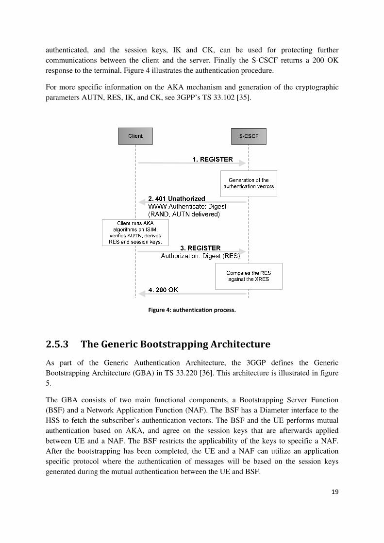
19
authenticated, and the session keys, IK and CK, can be used for protecting further
communications between the client and the server. Finally the S-CSCF returns a 200 OK
response to the terminal. Figure 4 illustrates the authentication procedure.
For more specific information on the AKA mechanism and generation of the cryptographic
parameters AUTN, RES, IK, and CK, see 3GPP’s TS 33.102 [35].
Figure 4: authentication process.
2.5.3 The Generic Bootstrapping Architecture
As part of the Generic Authentication Architecture, the 3GGP defines the Generic
Bootstrapping Architecture (GBA) in TS 33.220 [36]. This architecture is illustrated in figure
5.
The GBA consists of two main functional components, a Bootstrapping Server Function
(BSF) and a Network Application Function (NAF). The BSF has a Diameter interface to the
HSS to fetch the subscriber’s authentication vectors. The BSF and the UE performs mutual
authentication based on AKA, and agree on the session keys that are afterwards applied
between UE and a NAF. The BSF restricts the applicability of the keys to specific a NAF.
After the bootstrapping has been completed, the UE and a NAF can utilize an application
specific protocol where the authentication of messages will be based on the session keys
generated during the mutual authentication between the UE and BSF.
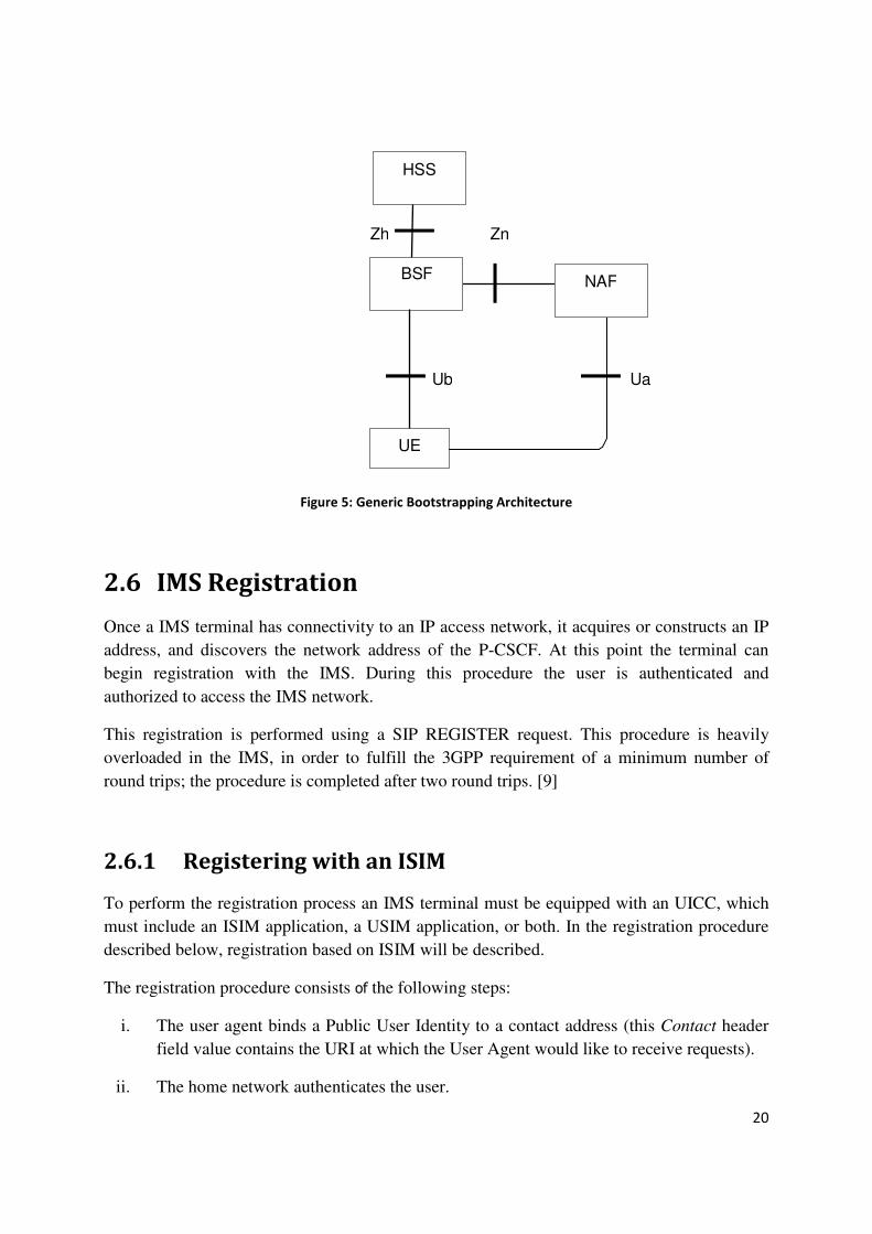
20
UE
HSS
BSF
UaUb
Zh Zn
NAF
Figure 5: Generic Bootstrapping Architecture
2.6 IMS Registration
Once a IMS terminal has connectivity to an IP access network, it acquires or constructs an IP
address, and discovers the network address of the P-CSCF. At this point the terminal can
begin registration with the IMS. During this procedure the user is authenticated and
authorized to access the IMS network.
This registration is performed using a SIP REGISTER request. This procedure is heavily
overloaded in the IMS, in order to fulfill the 3GPP requirement of a minimum number of
round trips; the procedure is completed after two round trips. [9]
2.6.1 Registering with an ISIM
To perform the registration process an IMS terminal must be equipped with an UICC, which
must include an ISIM application, a USIM application, or both. In the registration procedure
described below, registration based on ISIM will be described.
The registration procedure consists of the following steps:
i. The user agent binds a Public User Identity to a contact address (this Contact header
field value contains the URI at which the User Agent would like to receive requests).
ii. The home network authenticates the user.
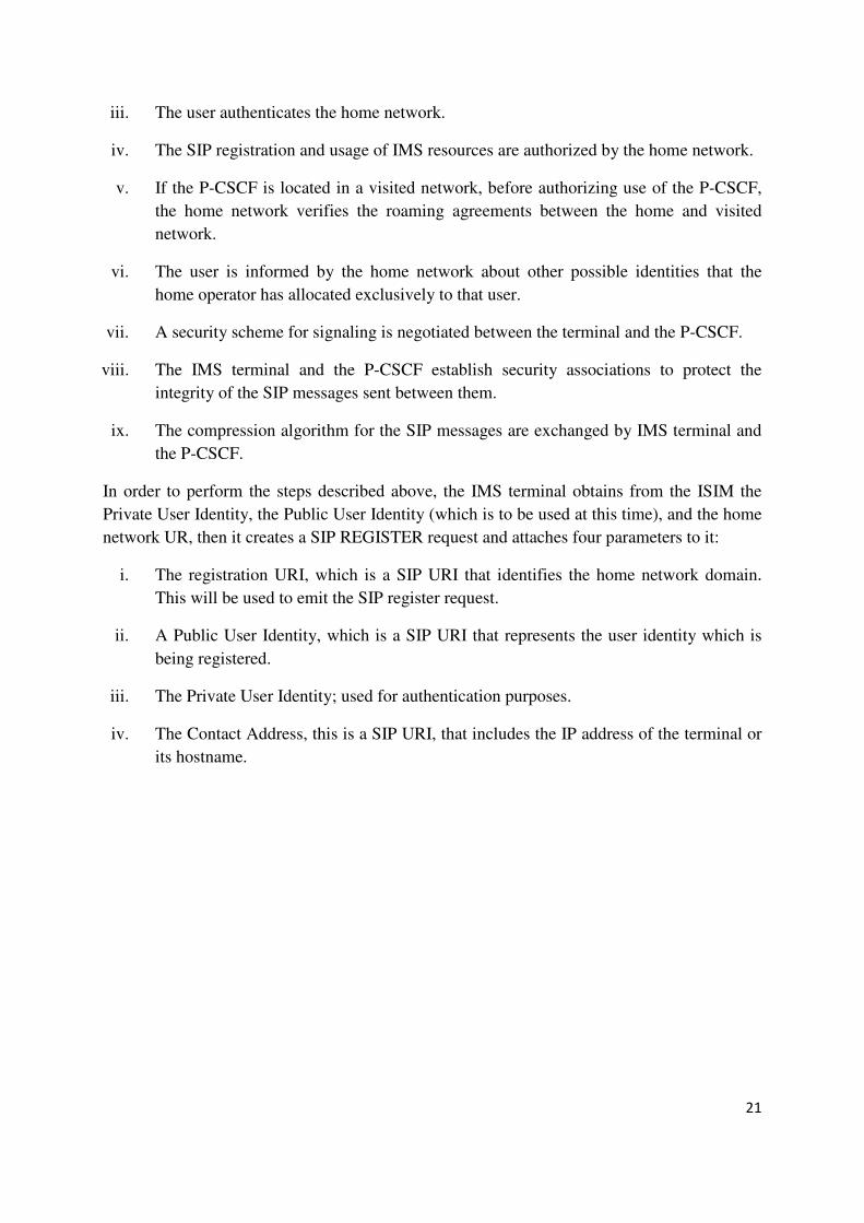
21
iii. The user authenticates the home network.
iv. The SIP registration and usage of IMS resources are authorized by the home network.
v. If the P-CSCF is located in a visited network, before authorizing use of the P-CSCF,
the home network verifies the roaming agreements between the home and visited
network.
vi. The user is informed by the home network about other possible identities that the
home operator has allocated exclusively to that user.
vii. A security scheme for signaling is negotiated between the terminal and the P-CSCF.
viii. The IMS terminal and the P-CSCF establish security associations to protect the
integrity of the SIP messages sent between them.
ix. The compression algorithm for the SIP messages are exchanged by IMS terminal and
the P-CSCF.
In order to perform the steps described above, the IMS terminal obtains from the ISIM the
Private User Identity, the Public User Identity (which is to be used at this time), and the home
network UR, then it creates a SIP REGISTER request and attaches four parameters to it:
i. The registration URI, which is a SIP URI that identifies the home network domain.
This will be used to emit the SIP register request.
ii. A Public User Identity, which is a SIP URI that represents the user identity which is
being registered.
iii. The Private User Identity; used for authentication purposes.
iv. The Contact Address, this is a SIP URI, that includes the IP address of the terminal or
its hostname.
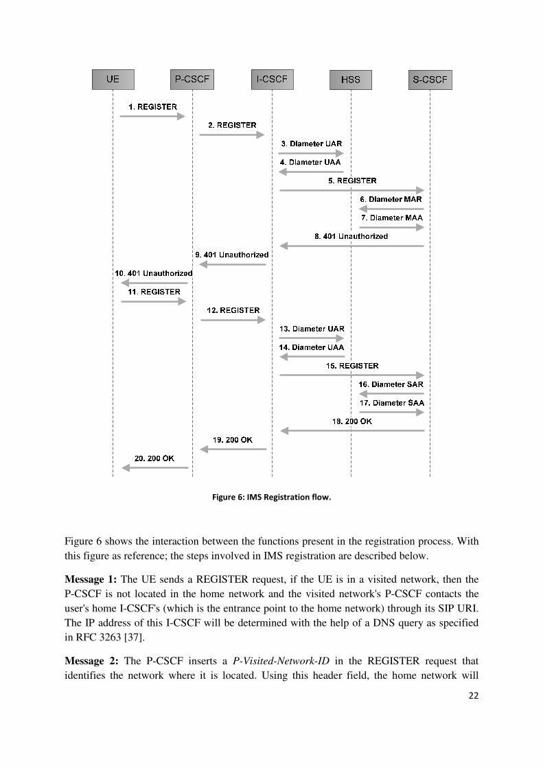
22
Figure 6: IMS Registration flow.
Figure 6 shows the interaction between the functions present in the registration process. With
this figure as reference; the steps involved in IMS registration are described below.
Message 1: The UE sends a REGISTER request, if the UE is in a visited network, then the
P-CSCF is not located in the home network and the visited network's P-CSCF contacts the
user's home I-CSCF's (which is the entrance point to the home network) through its SIP URI.
The IP address of this I-CSCF will be determined with the help of a DNS query as specified
in RFC 3263 [37].
Message 2: The P-CSCF inserts a P-Visited-Network-ID in the REGISTER request that
identifies the network where it is located. Using this header field, the home network will

23
check if there is an applicable roaming agreement between the networks. The P-CSCF also
inserts its own SIP URI in the Path header field, as a request to the home network, indicating
it should forward SIP requests for this URI through this P-CSCF. Finally the P-CSCF will
forward the SIP REGISTER request to the I-CSCF in the home network.
Message 3: To get authorization and discover if there is already an S-CSCF allocated to the
subscriber, the I-CSCF sends a Diameter User-Authentication-Request (UAR) to the HSS,
containing a Public User Identity, the Private User Identity, and the visited network identifiers
(all this information was contained in the REGISTER request).
Message 4: If the HSS authorizes the user to roam to the visited network, then it sends a
confirmation in a Diameter User-Authentication-Answer (UAA), which includes the SIP URI
of the previously allocated S-CSCF, if there was one. Otherwise, it returns a set of S-CSCF
capabilities to the I-CSCF, according to these capabilities the I-CSCF will chose a S-CSCF
that suits the user’s needs.
Message 5: The I-CSCF routes the SIP REGISTER request to the selected S-CSCF.
Message 6: The S-CSCF receives the REGISTER request and starts to authenticate the user.
It communicates with the HSS, downloads authentication data, and at the same time the
S-CSCF saves its own URI in the HSS. This URI may be used in the future, if the HSS is
queried for the same user, it will then return routing information pointing to this S-CSCF. For
this purpose the S-CSCF creates a Diameter Multimedia-Auth-Request (MAR) message and
sends it to the HSS.
Message 7: Once the HSS stores the S-CSCF URI along with this subscriber's data it
responds with a Diameter Multimedia-Auth-Answer (MAA) message.
Message 8-10: The S-CSCF creates a SIP 401 (Unauthorized) response and sends it to the
IMS terminal. This response includes a challenge/credential (as described in section 2.5.2) in
the WWW-Authenticate header field that the IMS terminal should respond to.
Message 11-12: The IMS terminal sends a new SIP REGISTER request to the P-CSCF. The
P-CSCF performs the same operations as for the first REGISTER request.
Message 13: The I-CSCF sends a new Diameter UAR message.
Message 14: The HSS responses with a UAA, including routing information, the SIP URI of
the S-CSCF allocated to the user (as previously stored by the HSS when it received a
Diameter MAR in message 6). Note that, it does not matter if the I-CSCF used for this second
REGISTER request is the same I-CSCF as in the first REGISTER request, since the second
REGISTER request will end up at the same S-CSCF.
Message 15: When the REGISTER request is received by the S-CSCF, the response includes
the user’s credentials, which are validated against the authentication vectors, provided earlier
by the HSS in the Diameter MAA message (message 7).
24
Message 16-17: If the authentication was successful, then the S-CSCF sends a Diameter
Server-Assignment-Request (SAR) message to the HSS, to download the subscriber's user
profile, and to inform the HSS that the subscriber has been registered. At this point the
S-CSCF has stored the contact URI of the user, present in the Contact header field, and the
list of URIs included in the Path header field of the SIP REGISTER request, the S-CSCF will
later route the SIP requests addressed to the user via this URI list. The HSS sends back the
information through a Server-Assignment-Answer (SAA) command.
Message 18-20: Finally, the S-CSCF sends a 200 OK response to the REGISTER request,
which indicates success; it includes a P-Associated-URI header field that holds a list of URIs
assigned to the user, a Service-Route header field that includes a list of SIP servers URIs.
Future SIP requests that the IMS terminal sends, will be routed via these SIP servers, in
addition to the P-CSCF. The registration procedure is now completed.
The IMS terminal will be registered with the IMS for the duration indicated in the expire
parameter of the SIP 200 OK message’s Contact header field. [9]
2.7 Real-time technologies: SIP, RTP and XMPP
The best technologies and protocols for creating real-time Internet applications are still being
sorted out. In today’s market there are a wide range of proprietary technologies (e.g., VoIP
providers, IM services, gaming communities, etc.) as well as products built on a mix of
standardized protocols. Even though proprietary solutions can be very successful, over time
the market and regulation pressures have tended to push towards standard-based solutions,
since large enterprises, service providers, and governments do not want to be locked in to
proprietary technologies.
As previously mentioned SIP enables network endpoints to negotiate and manage (call-setup
and call-management functionalities) data streams but does not handle the data itself. SIP’s
negotiation results in a “handoff” to a data streaming protocol such as RTP for multimedia,
SIP it has been widely adopted as the basis for voice and video services over the Internet. SIP
is being extended to handle messaging and presence via SIP for Instant Messaging and
Presence Leveraging Extensions (SIMPLE). However, because SIP was designed for session
negotiation, the SIMPLE extensions that are under development are still not optimized for
rapid exchange of advanced structured data.
RTP has rapidly supplanted older technologies such as the International Telecommunications
Union’s H.323 standard. RTP is optimized only for certain types of real-time transport, such
as computationally intensive, loss-tolerant binary data streams, where quality of service is the
not so important (e.g., a VoIP calls where packet drop is acceptable, since small amounts of
data loss can be compensated by software and the human ear). Transporting structured data
such as Simple Object Access Protocol (SOAP) requests or Really Simple Syndication (RSS)
feeds over RTP, might cause that critical information gets lost.
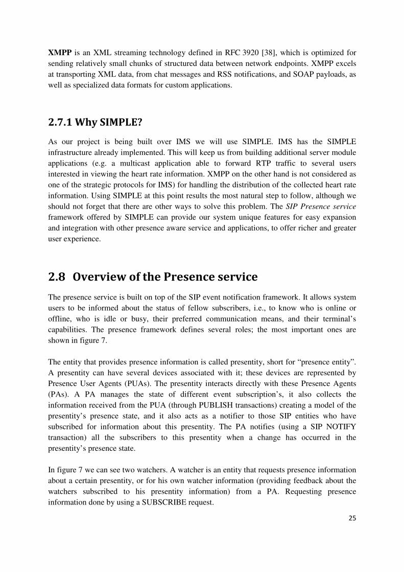
25
XMPP is an XML streaming technology defined in RFC 3920 [38], which is optimized for
sending relatively small chunks of structured data between network endpoints. XMPP excels
at transporting XML data, from chat messages and RSS notifications, and SOAP payloads, as
well as specialized data formats for custom applications.
2.7.1 Why SIMPLE?
As our project is being built over IMS we will use SIMPLE. IMS has the SIMPLE
infrastructure already implemented. This will keep us from building additional server module
applications (e.g. a multicast application able to forward RTP traffic to several users
interested in viewing the heart rate information. XMPP on the other hand is not considered as
one of the strategic protocols for IMS) for handling the distribution of the collected heart rate
information. Using SIMPLE at this point results the most natural step to follow, although we
should not forget that there are other ways to solve this problem. The SIP Presence service
framework offered by SIMPLE can provide our system unique features for easy expansion
and integration with other presence aware service and applications, to offer richer and greater
user experience.
2.8 Overview of the Presence service
The presence service is built on top of the SIP event notification framework. It allows system
users to be informed about the status of fellow subscribers, i.e., to know who is online or
offline, who is idle or busy, their preferred communication means, and their terminal’s
capabilities. The presence framework defines several roles; the most important ones are
shown in figure 7.
The entity that provides presence information is called presentity, short for “presence entity”.
A presentity can have several devices associated with it; these devices are represented by
Presence User Agents (PUAs). The presentity interacts directly with these Presence Agents
(PAs). A PA manages the state of different event subscription’s, it also collects the
information received from the PUA (through PUBLISH transactions) creating a model of the
presentity’s presence state, and it also acts as a notifier to those SIP entities who have
subscribed for information about this presentity. The PA notifies (using a SIP NOTIFY
transaction) all the subscribers to this presentity when a change has occurred in the
presentity’s presence state.
In figure 7 we can see two watchers. A watcher is an entity that requests presence information
about a certain presentity, or for his own watcher information (providing feedback about the
watchers subscribed to his presentity information) from a PA. Requesting presence
information done by using a SUBSCRIBE request.
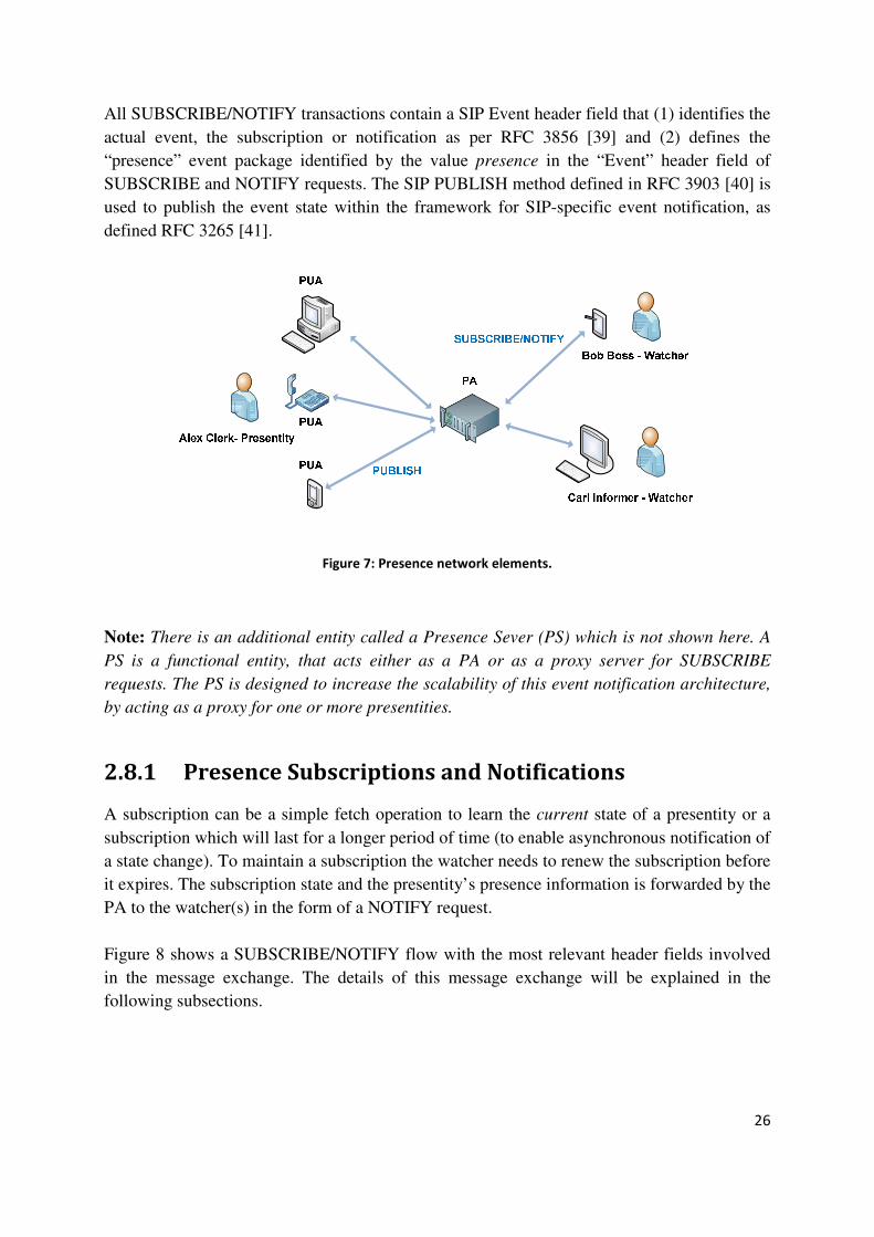
26
All SUBSCRIBE/NOTIFY transactions contain a SIP Event header field that (1) identifies the
actual event, the subscription or notification as per RFC 3856 [39] and (2) defines the
“presence” event package identified by the value presence in the “Event” header field of
SUBSCRIBE and NOTIFY requests. The SIP PUBLISH method defined in RFC 3903 [40] is
used to publish the event state within the framework for SIP-specific event notification, as
defined RFC 3265 [41].
Figure 7: Presence network elements.
Note: There is an additional entity called a Presence Sever (PS) which is not shown here. A
PS is a functional entity, that acts either as a PA or as a proxy server for SUBSCRIBE
requests. The PS is designed to increase the scalability of this event notification architecture,
by acting as a proxy for one or more presentities.
2.8.1 Presence Subscriptions and Notifications
A subscription can be a simple fetch operation to learn the current state of a presentity or a
subscription which will last for a longer period of time (to enable asynchronous notification of
a state change). To maintain a subscription the watcher needs to renew the subscription before
it expires. The subscription state and the presentity’s presence information is forwarded by the
PA to the watcher(s) in the form of a NOTIFY request.
Figure 8 shows a SUBSCRIBE/NOTIFY flow with the most relevant header fields involved
in the message exchange. The details of this message exchange will be explained in the
following subsections.
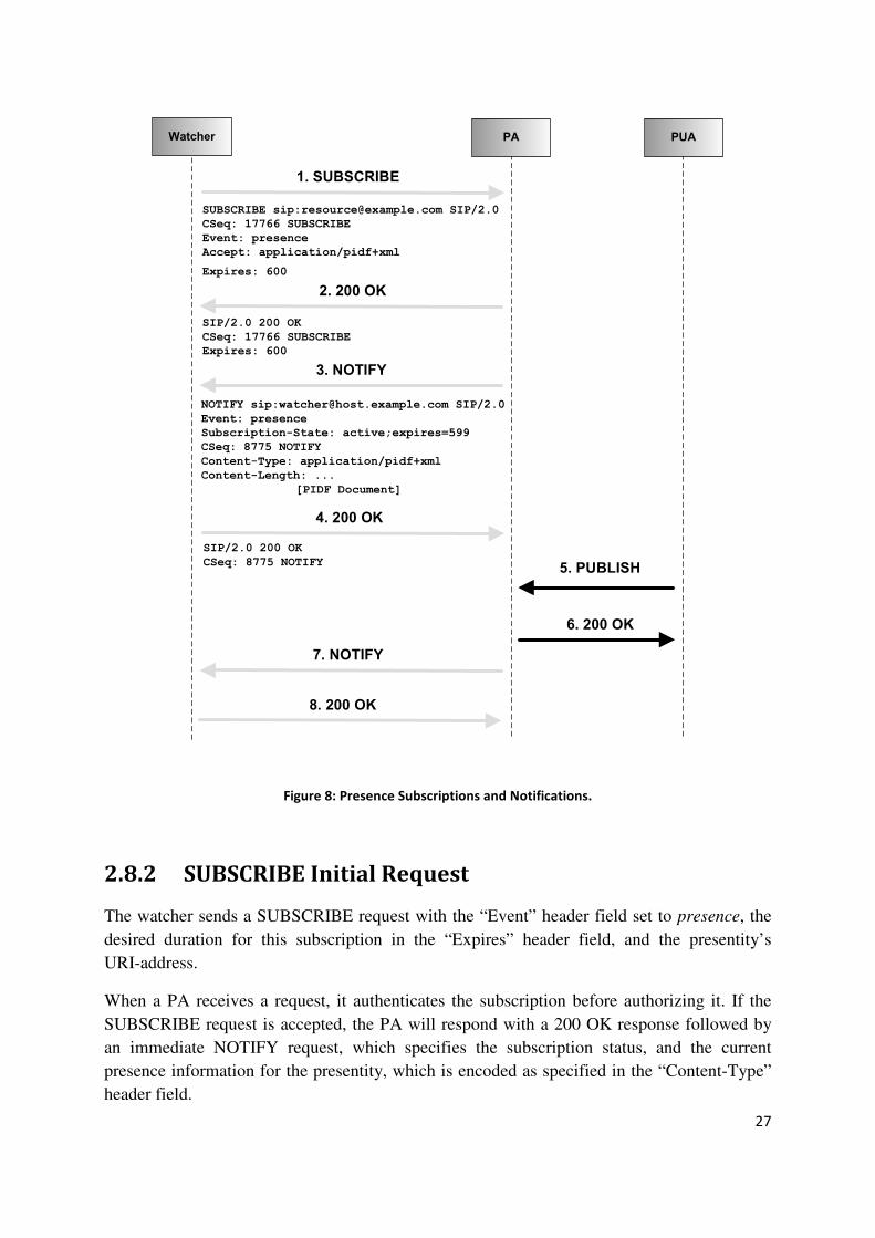
27
Watcher PA PUA
1. SUBSCRIBE
2. 200 OK
3. NOTIFY
4. 200 OK
7. NOTIFY
8. 200 OK
5. PUBLISH
SUBSCRIBE sip:[email protected] SIP/2.0
CSeq: 17766 SUBSCRIBE
Event: presence
Accept: application/pidf+xml
Expires: 600
SIP/2.0 200 OK
CSeq: 17766 SUBSCRIBE
Expires: 600
NOTIFY sip:[email protected] SIP/2.0
Event: presence
Subscription-State: active;expires=599
CSeq: 8775 NOTIFY
Content-Type: application/pidf+xml
Content-Length: ...
[PIDF Document]
SIP/2.0 200 OK
CSeq: 8775 NOTIFY
6. 200 OK
Figure 8: Presence Subscriptions and Notifications.
2.8.2 SUBSCRIBE Initial Request
The watcher sends a SUBSCRIBE request with the “Event” header field set to presence, the
desired duration for this subscription in the “Expires” header field, and the presentity’s
URI-address.
When a PA receives a request, it authenticates the subscription before authorizing it. If the
SUBSCRIBE request is accepted, the PA will respond with a 200 OK response followed by
an immediate NOTIFY request, which specifies the subscription status, and the current
presence information for the presentity, which is encoded as specified in the “Content-Type”
header field.

28
2.8.3 SUBSCRIBE Refresh request
As noted above, when a watcher wishes to maintain an active subscription, it must refresh the
subscription before the subscription expires. This is accomplished by sending a SUBSCRIBE
refresh within the same dialog as the initial SUBSCRIBE with the “Event” header set to
presence. If the request is accepted by the PA, then the subscription’s expiration timer is
updated and set to the smaller of the time specified in the SUBSCRIBE request (if any) or the
duration specified by the PA. The watcher is informed about the subscription state and new
expiration time via an immediate NOTIFY.
2.8.4 SUBSCRIBE Poll request
A Subscribe Poll request is used by a watcher to learn the current presence information from a
presentity as a one-time notification. Polling or fetching presence information from a
presentity is done by issuing a SUBSCRIBE request with the “Expires” header field set to
zero. The SUBSCRIBE request does not contain a body. If the operation is supported and
authorized by the PA, then the watcher will receive a notification from the PA with the
current presence information, a "Subscription-State" value of "terminated", and a "reason"
parameter of "timeout". Any outstanding subscription of this watcher will be cancelled (due to
the specification of a zero expires time).
2.8.5 Watcher-side subscription termination
A subscription is immediately terminated by sending a SUBSCRIBE request with the
“Expires” header field set to zero, this must be done within the same dialog as the initial
SUBSCRIBE. This operation will terminate the subscription at the PA, thus ending
notifications related to that subscription. A successful request will be followed by a
notification containing the most recent presence information, with the “Expires” header field
set to zero.
2.8.6 Server-side subscription termination
The PA can terminate a subscription at any time by sending a NOTIFY request. The
“Subscription-state” header field is set to terminated and the reason parameter will indicate
the cause. The NOTIFY request will contain the most current presence information, in
addition to the reason for termination

29
2.9 Presence Publication
The purpose of a SIP PUBLISH method is to publish the event state used within the
framework for a SIP-specific event notification. [41] Figure 9 shows an example of such a
message flow with the most relevant header fields for this method. These fields will be
explained in more detail in the following subsections.
PA PUA
1. PUBLISH
2. 200 OK
PUBLISH sip:[email protected] SIP/2.0
CSeq: 1 PUBLISH
Expires: 3600
Event: presence
Content-Type: application/pidf+xml
Content-Length: ...
[PIDF document]
SIP/2.0 200 OK
CSeq: 1 PUBLISH
SIP-ETag: dx200xyz
Expires: 1800
Figure 9: PUBLISH request.
2.9.1 PUBLISH Initial request
To create a new publication an initial PUBLISH request is emitted by the PUA. The message
should contain an “Expires” header field set to the expiration time, and the presentity's
presence information in the message body is in the format indicated by “Content-Type”
header field. Every new successful PUBLISH request is assigned an identifier by the PA, in
the form of an entity-tag specified in header field “SIP-Etag”. These entity-tags are unique for
each PUA. This means that two instances of published presence information can have the
same entity-tag value, as long as they are not published for the same user agent. If the
publication is authorized and successful, the response message will have the “Expires” header
field set, indicating the validity of the publication. The entity-tag for the new publication is
also included in the response message.

30
2.9.2 PUBLISH Refresh request
The PUBLISH Refresh request operation enables a presentity, to refresh previously published
presence information in the PA before it expires. This is done by sending a PUBLISH refresh
request. The request must contain the entity-tag of the publication to be refreshed in the
“SIP-If-Match” header field, and an expiration time in the “Expires” header field. A
PUBLISH refresh only extends the expiration time of an existing publication, it does not
affect the presence information in any other way; the request shall not contain a message body
(therefore the header field “Content-Length” is always set to 0). In the response, the “Expires"
header field indicates the actual duration for which the publication will remain active. If the
Expires header field is left out, a default “Expiry” time will be used. No new entity-tag for the
refreshed publication is created. A PUBLISH refresh for an invalid entity-tag will fail.
2.9.3 PUBLISH Modify request
This operation enables the presentity to modify existing presence information present in the
PA. Modifying presence information means that the initial presence information is replaced
by the new presence information in the PA. This is done to avoid creating completely new
presence information. The request must specify the entity-tag of the publication to be
modified in the “SIP-If-Match” header field. Optionally an expiration time may be included in
the “Expires” header field. The request must also contain a body that includes the modified
presence information. If the operation is successful, then the response will indicate the
duration for which the publication will remain active, along with a newly created entity-tag
for the modified publication. If the request did not contain an “Expires” header field, then the
PA will chose one, according to prestablished criteria. A PUBLISH modify request for an
invalid entity-tag will fail, this applies to all the PUBLISH requests.
2.9.4 PUBLISH Remove request
This operation enables a presentity to remove an existing publication from its PA before the
expiration time. The PUBLISH remove request must contain the entity-tag of the publication
to be removed in the “SIP-If-Match” header field, and must have the “Expires” header field
set to zero. A PUBLISH remove request affects only the expiration time, and it shall not
contain a body (hence the “Content-Length” is always zero). If the operation succeeds, the
response message will have the “Expires” header field set to zero, as a confirmation that the
publication has been terminated.
Note: Removing presence information is effectively a refresh of the information with an
infinitesimal expiration interval. Consequently, the presence information expires immediately
after it has been refreshed.

31
2.10 The Presence service in the IMS
The presence architecture for IMS was defined by the 3GPP in their technical specification
TS 23.141 [42]. Figure 10 shows the principal elements involved. The ASs located in the
home network can acts as PAs. The Resource List Server (RLS) is also implemented in ASs.
An AS can be a watcher for presence information; this enables it to spread presence
information to various services.
A PUA can be implemented using an AS. In this case, the PUA can obtain presence
information from any potential source of information in the network, such as the HSS, the
Mobile Switching Center/Visited Location Register (MSC/VLR) in circuit-switched
networks, the Serving GPRS Support Node (SGSN) or the GGSN in GPRS networks, or the
S-CSCF (due to IMS registration). This PUA can publish the acquired information directly to
the PA.
Terminals in an IMS network can interact directly with an AS that is acting as a PA or RLS.
This interface can be used to configure resource lists (such as presence lists) and change data,
authorize watchers, etc. The protocol used is the XML Configuration Access Protocol
(XCAP) as defined in RFC 4825 [43]. Further details are given in [9].
Access
Network
Access
Network
P-CSCF
P-CSCF
I-CSCF
HSS
SLF
ISC
Mw
Mw
Mw
Mw
ShISC
Sh Si
Cx
Dx
Dx
Cx
ISC
PUA (AS) RLS (AS)
S-CSCF
PA (AS)
ShISC
Watcher (AS)
Figure 10: the Presence entities in IMS.

32
2.10.1 Watcher Subscription
A watcher within an IMS presence service can subscribe to individual presentity information
or to complete presence lists. These presence lists are a list of SIP-URIs that map to specific
presentities. These presence lists are stored in an RLS. Using a presence list is more efficient
than subscribing to each presentity’s presence information, as it reduces the number of
messages exchanged between a watcher and PA. Thus only a single SUBSCRIBE request is
sent to the watcher’s presence list. The RLS acts on behalf of the watcher, performing all the
subscription requests to the listed presentities.
2.10.2 Presence publication
When an IMS PUA sends a PUBLISH request intended for the presence service, the S-CSCF
evaluates the request according to the initial filter criteria (which were downloaded by the
S-CSCF in the PUA’s registration process, as they are part of the subscriber’s profile) for this
presentity. If the request is permitted, then the request is forwarded to the AS acting as a PA,
where the presentity’s presence information is stored. If the PA authorizes publication of this
presence information, then it will respond with a 200 OK.
2.10.3 The Presence and Group Management (PGM)
Ericsson has developed a concept for managing presence information and group data for IMS.
This concept introduces a Presence and Group Management (PGM) server. This presence
server can manage group resources. The PGM permits a PUA to effect the following
operations: update presence information, subscribe to others’ presence information, and
subscribe to the list of buddies that watch the presentity’s presence information. The PGM can
allow or block others from watching the PUA’s presentity’s presence information. The PUA
can retrieve the list of buddies who are allowed and blocked, and retrieve group lists. The
PUA can add, remove, and modify buddies in a group. Modification or removals of groups
are also possible.
2.11 Sensor network
The sensor node and the accessory equipment used in this project were provided by
SUUNTO. The principal device is the chest belt model T6 [44] for heart rate monitoring. This
is a wearable sensor with a processing unit that communicates with other equipment through
ANT™ [45] radio technology (described further below). In addition to the chest belt, there is
the “All-In-One” module, which is an experimental (is still under a development stage no
official documentation is available) hardware that acts as gateway, between networks
implementing ANT and Bluetooth networks running the Simple Sensor Interface (SSI) [46]

33
protocol. The “All-In-One” modules enables communication between the heart rate monitor
(HRM) and Bluetooth enabled devices. The chest belt comes with an ANT RF transceiver
with a USB interface; this is a standard accessory for the T6 [44]. This ANT RF transceiver
may be connected to any terminal that can act as a USB master [47], offering the possibility to
interact with the HRM directly using ANT.
Figure 11 illustrates a possible sensor networking scenario, where a personal computer (PC)
interacts with the HRM through an ANT USB adaptor. A mobile terminal communicates with
the HRM by interacting with the All-In-One module. Such a module is needed as no currently
available mobile phone handsets offer USB master support (specifically they lack the ability
to power an attached USB device), so far only one Internet tablet have been found that in
theory satisfies the required needs [48]. However, it might be possible to design a USB
On-the-go device which could contain an ANT transceiver. Figure 12 illustrates the HRM,
USB ANT transceiver, and the All-in-one module.
Figure 11: sensor network elements.
Note: An alternative solution to having an ANT-to-Bluetooth converter is offered by a product
that was announced earlier this year by Spectec Computer Company Ltd. They launched the
SDA-320 miniSDIO ANT RF card that uses Nordic Semiconductor’s ANT specific
nRF24AP1™ [49] 2.4 GHz ultra-low power transceiver, which allows a miniSDIO card slot-
equipped Smartphone or PDA to communicate with ANT enabled sensors. [50]

34
Figure 12: heart rate monitor, USB ANT transceiver, and All-in-one module.
Note: There are several companies that offers similar products to the T6 heart rate monitor
(e.g. Polar [51], Beurer [52], and Globalst [53]), in principal they are more or less the same,
and their functionalities and usage are similar; basically a chest strap that has a sensor, a
radio transmitter, and a computing unit that communicates with a wearable computer, that
has more processing power and storage, it provides the user with different options and
functionalities (e.g. display the elapsed session time, calorie burn, heartbeat rate, etc.).
2.11.1 ANT
ANT is a low power, low duty cycle radio frequency technology that operates in the 2.4 GHz
industrial, scientific and medical spectrum for wireless sensor networks. It is based on Time
Division Multiple Access (TDMA). ANT was designed for easy implementation of
point-to-point, star, tree, and meshes networks; among its features are design simplicity,
efficiency, reliable data transmission, cross-talk immunity, ultra-low power consumption, and
low system costs. Millions of ANT nodes have been deployed. ANT is well suited for low
data rate sensor network topologies. [45]
ANT’s protocol stack is extremely compact, allowing a low-cost 4-bit or 8-bit microcontroller
to establish and maintain complex wireless networks, reducing system costs. Data transfers
can be done in a deterministic or ad hoc fashion. The use of burst mode allows a more
efficient transfer of large amounts of stored data to and from a PC or other computing device
(e.g. when transferring data files from a wearable computer to a personal computer). ANT
provides the physical, network, and transport OSI layers. In addition, ANT incorporates a
network key [54] that provides a foundation for user-defined low-level security
implementations. Figure 13 illustrates the protocol layers implemented by ANT.
Heartbeat rate monitor
USB ANT transceiver
All-in-one module

35
Figure 13: OSI Layer model of ANT.
A typical ANT enabled device consists of an application host microcontroller interfaced with
an ANT module, chipset, or chip. The host microcontroller establishes and maintains a
communication session to other remote ANT enabled devices through a simple serial message
protocol. A typical serial message has the format shown in figure 14.
1 1 1 n 1
SYNC MSG Length MSG Id Payload Checksum
Figure 14: ANT serial message.
A message begins with a SYNC byte and ends with a checksum. The bytes are sent with the least significant bit transmitted first. Table 3 describes the serial message in more detail. For details on ANT’s message protocol see [54]
Application/Presentation
Layers
Higher Level Security
Network / Transport and
Low Level Security
Data Link Layer
Physical Layer
User defined
ANT implemented

36
Table 3: ANT serial message
Byte number Name Length Description
0 Sync 1 Byte Fixed value of 10100100
1 MSG Length 1 Byte Number of data bytes in
the message 1 < N < 9
2 MSG Id 1 Byte 0: Invalid
1 - 255: Data Type
3 … N+2 Payload N Byte Data bytes
N+3 CRC 1 Byte XOR of all previous bytes
including the SYNC byte
2.11.2 Simple Sensor Interface (SSI)
The SSI communications protocol [46] is intended to be used for transferring data between
sensor unit(s) and a terminal. There are two modes of operation of the SSI protocol:
point-to-point and networking applications.
In the point-to-point case the SSI protocol operates over a serial link*. This can be a physical
(wired) or wireless link, such as the Bluetooth serial port profile. The SSI protocol can be
used over layer three transport protocols, such as TCP/IP or nanoIP [55]. The SSI protocol is
asynchronous and stateless; each frame consists of three parts: header, payload, and an
optional CRC checksum. The header structure and length may change from case to case, but
the structure of the payload is always the same. The SSI protocol bytes are ordered as Big
Endian (i.e., most significant byte first).
A point-to-point connection is the protocol schema used in this project. It will be briefly
described here, for more details refer to [46].
* [46] refers to this as the SSI UART protocol, even though it does not involve a universal
asynchronous receiver/transmitter.

37
The SSI UART protocol uses a message structure shown in figure 15. All messages use the
same frame format: header, message body, and an optional two byte CRC checksum field.
1 2 2 n 2
Start MSG Length ~MSG Length Payload CRC
Figure 15: SSI UART protocol frame structure.
The message Header is 5 bytes long: it contains a start byte equal to 0xFE, a length field that
describes the message length in two bytes, and a field that is the bitwise complement of the
length field. This header is used to identify the start of the payload.
The Payload has a variable size. The payload contains the device’s address, command code,
and other attributes. The payload structure does not depend upon the type of connection. The
first byte of the payload is always an address and the second byte a command. These are
present within every SSI payload structure. The other parts depend upon the command. The
address field is required to separate multiple sensor devices on a single communication
device. The address field is always present and is one byte long. Address fields are always
written as hexadecimal numbers (0x00 – 0xFF). The command field is one byte long, this
allows 255 different alternatives. However, each command has two variants (with and without
a CRC checksum), thus 127 different commands are possible. Within each command the
payload field structure remains the same. For further details see [46].
The CRC checksum is optional; i.e., is only present in the message if the executed commands
specifically request it. The CRC checksum is calculated over the payload. If the CRC is not
correct, then the message has to be ignored.
The SSI Networking Protocol has the capability to run over layer 3 networking protocols,
such as TCP/IP or nanoIP. SSI operates in a similar way over all the compatible socket based
network protocols. An example of the message structure used for nanoIP (specifically
nanoUDP) is given in figure 16. nanoIP consists of two transport techniques, nanoUDP which
is an unreliable simple transport, and nanoTCP which provides retransmissions and flow
control with the cost of message size and increased network traffic. [56, 57]
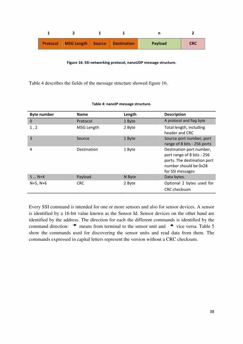
38
1 2 1 1 n 2
Protocol MSG Length Source Destination Payload CRC
Figure 16: SSI networking protocol, nanoUDP message structure.
Table 4 describes the fields of the message structure showed figure 16.
Table 4: nanoIP message structure.
Byte number Name Length Description
0 Protocol 1 Byte A protocol and flag byte
1 , 2 MSG Length 2 Byte Total length, including
header and CRC
3 Source 1 Byte Source port number, port
range of 8 bits - 256 ports
4 Destination 1 Byte Destination port number,
port range of 8 bits - 256
ports. The destination port
number should be 0x28
for SSI messages
5 … N+4 Payload N Byte Data bytes.
N+5, N+6 CRC 2 Byte Optional 2 bytes used for
CRC checksum
Every SSI command is intended for one or more sensors and also for sensor devices. A sensor
is identified by a 16-bit value known as the Sensor Id. Sensor devices on the other hand are
identified by the address. The direction for each the different commands is identified by the
command direction: means from terminal to the sensor unit and vice versa. Table 5
show the commands used for discovering the sensor units and read data from them. The
commands expressed in capital letters represent the version without a CRC checksum.

39
Table 5: SSI commands.
Command Direction Description
Q/q (0x51/0x71) Query
A/a (0x41/0x61) Query reply
R/r (0x52/0x72) Request sensor data
V/v (0x56/0x76) Sensor data response
The Query commands Q/q are executed by the client to obtain information related to the
sensor unit, in response to this query the sensor unit replies with a Query reply command A/a.
Figure 17 shows the message direction.
Figure 17: message direction of Q/q and A/a commands.
A Q command message could look like the one shown in figure 18. Here the message header
starts with the default value 0xFE (to identify the message start). The following message field
is the Length (MSG Length) field which specifies the total length of the packet in bytes; in
this case it is 7 bytes long. After the Length field comes the bitwise complement of the Length
field (~MSG Length), as mentioned before it is used to identify the start of the Payload. In the
Payload we can find the address (Addr) of the sensor unit and the command (Cmd) identifier.
The value 0x51 represents the Q command. In this case we are querying the sensors broadcast
address 0x3F, all the adjacent sensors will be able to here and reply to the query, this is used
for sensor unit discovery.
Start MSG Length ~MSG Length Payload
FE 0 7 FF F8 3F 51
Addr Cmd
Figure 18: ‘Q’ command message (values are shown in hexadecimal).
Q/q
A/a (sensor information)
Client Sensor unit
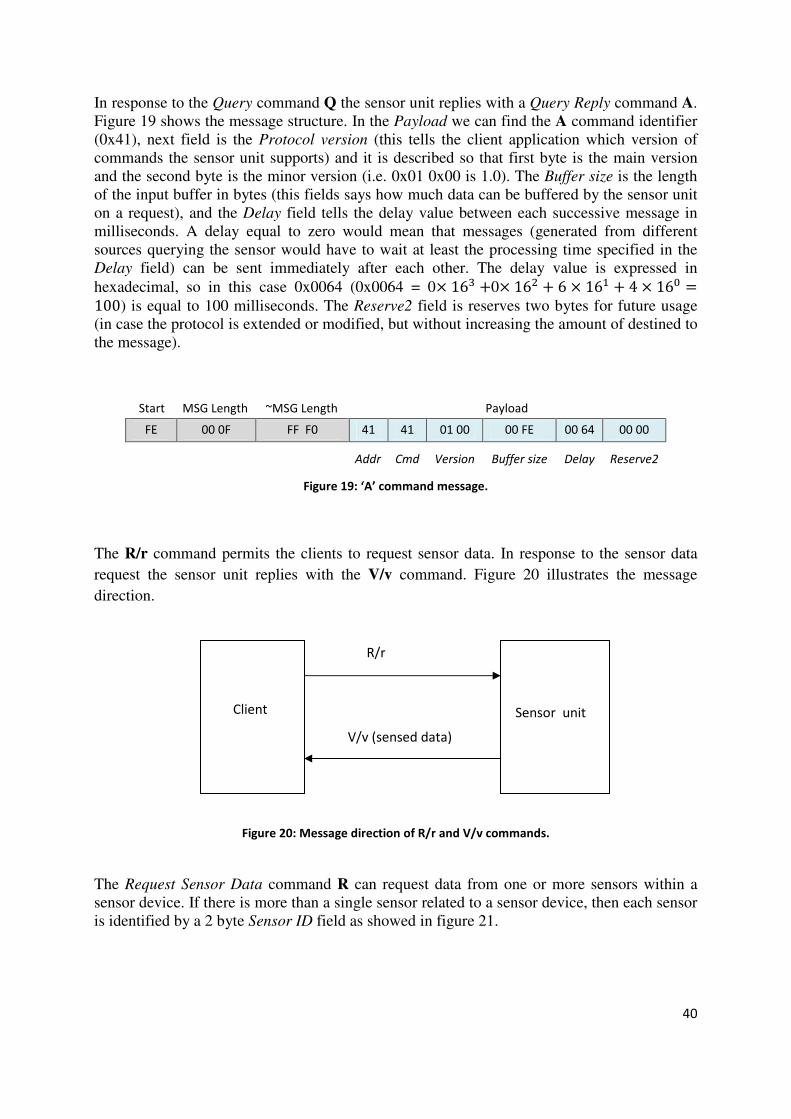
40
In response to the Query command Q the sensor unit replies with a Query Reply command A. Figure 19 shows the message structure. In the Payload we can find the A command identifier (0x41), next field is the Protocol version (this tells the client application which version of commands the sensor unit supports) and it is described so that first byte is the main version and the second byte is the minor version (i.e. 0x01 0x00 is 1.0). The Buffer size is the length of the input buffer in bytes (this fields says how much data can be buffered by the sensor unit on a request), and the Delay field tells the delay value between each successive message in milliseconds. A delay equal to zero would mean that messages (generated from different sources querying the sensor would have to wait at least the processing time specified in the Delay field) can be sent immediately after each other. The delay value is expressed in
hexadecimal, so in this case 0x0064 (0x0064 = 0� 16� �0� 16� � 6 � 16� � 4 � 16
100) is equal to 100 milliseconds. The Reserve2 field is reserves two bytes for future usage (in case the protocol is extended or modified, but without increasing the amount of destined to the message).
Start MSG Length ~MSG Length Payload
FE 00 0F FF F0 41 41 01 00 00 FE 00 64 00 00
Addr Cmd Version Buffer size Delay Reserve2
Figure 19: ‘A’ command message.
The R/r command permits the clients to request sensor data. In response to the sensor data
request the sensor unit replies with the V/v command. Figure 20 illustrates the message
direction.
Figure 20: Message direction of R/r and V/v commands.
The Request Sensor Data command R can request data from one or more sensors within a sensor device. If there is more than a single sensor related to a sensor device, then each sensor is identified by a 2 byte Sensor ID field as showed in figure 21.
R/r
V/v (sensed data)
Client Sensor unit
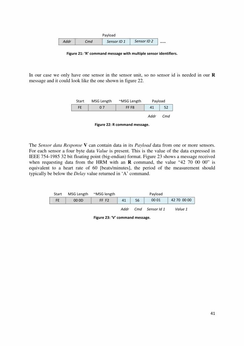
41
Payload
Addr Cmd Sensor ID 1 Sensor ID 2 ……
Figure 21: ‘R’ command message with multiple sensor identifiers.
In our case we only have one sensor in the sensor unit, so no sensor id is needed in our R message and it could look like the one shown in figure 22.
Start MSG Length ~MSG Length Payload
FE 0 7 FF F8 41 52
Addr Cmd
Figure 22: R command message.
The Sensor data Response V can contain data in its Payload data from one or more sensors. For each sensor a four byte data Value is present. This is the value of the data expressed in IEEE 754-1985 32 bit floating point (big-endian) format. Figure 23 shows a message received when requesting data from the HRM with an R command, the value “42 70 00 00” is equivalent to a heart rate of 60 [beats/minutes], the period of the measurement should typically be below the Delay value returned in ‘A’ command.
Start MSG Length ~MSG length Payload
FE 00 0D FF F2 41 56 00 01 42 70 00 00
Addr Cmd Sensor Id 1 Value 1
Figure 23: ‘V’ command message.

42
3 Related work
This section mentions some of the related work, including existing products on the market and
others that are being developed, that could be direct competitors to this system. We will
specifically mention some of the research which is being done on sensing within the scope of
health care and environmental sensing. Products such as a clinical health monitor used in
fixed environments are not considered, because they lack the mobility that is one of the
important characteristics of this project. No deep technical details about sensors, protocols, or
signaling will be given, as little detailed information of this kind has been found (as of the
date of writing this report). Additionally, a more rigorous study of these technologies is out of
the scope of this thesis project as the field is extremely broad.
3.1 Competing products
There are few directly competing products that have the same objective market and there are
also few major players involved. In this section we will primarily focus on the competing
products and their main functionalities.
3.1.1 Nokia Eco Sensor Concept
Nokia is developing a system that called the Nokia Eco Sensor Concept. It consists of a
wearable sensor device, which will be able to sense and analyze certain environmental
variables, as well as monitor the wearer's health and local weather conditions. The sensing
devices will be customizable to the user’s needs and desires. The users will be able to choose
which sensors they want to have included inside the sensing device. These sensors will
interoperate with a mobile phone.
The data collected by the sensor devices can be shared and viewed by other users. This system
is intended to help people stay connected to others, while at the same time being aware of
their health and local environment. [58]
3.1.2 MiCoach
The Adidas-Samsung collaboration has developed a system called MiCoach that was released
in the European market in the middle of March 2008. The system is designed to help, direct,
and motivate users in their training by combining a mobile phone, heart rate monitor, stride
sensor, MP3 player, and the voice of an electronic "personal coach." The user gets feedback
through the mobile phone about speed, distance, and heartbeat rate. If the user selects a

43
training plan, then the “personal coach” will advise the user on how to proceed when running.
[59]
3.1.3 Nike+iPod
The Nike+iPod system was annouced in May 2006. The system consists of a small
accelerometer attached or embedded in a shoe, which communicates with a receiver plugged
into an iPod nano. The iTunes software can be used to view the recorded exercise session.
The system is able to store information such as the elapsed time of the workout, the distance
traveled, pace, or calories burned by the person wearing the shoes, and display it on the iPod's
screen or play it through the headphones attached to an iPod. [60]
This product has a community site called Runners+, where users can upload their data and
compare it to others training sessions, and results. In the site you can also find running maps,
a thriving forums area, groups, videos, and more. [8]
3.1.4 SDA-320
In February of 2008 Spectec Computer Company Ltd. launched the SDA-320 miniSDIO ANT
RF card that uses Nordic Semiconductor’s ANT specific nRF24AP1™ [49] 2.4 GHz
ultra-low power transceiver, which allows a miniSDIO card slot-equipped smartphone or
PDA to wirelessly communicate, collect and analyze data from sports performance and health
monitoring sensors such as heart rate straps and speed/distance activity monitors.
The limitation of this system, is that their software runs only on Motorola Q phones using the
Windows® CE 6.0 OS, but Spectec is planning to provide support for other smartphones,
PDAs, and operating systems. [50]
3.1.5 Comparative analysis
The major advantage of this project compared to the previously mentioned products, besides
the offered mobility, data sharing, and real-time communication between the sensors and the
data network, is that it uses the IMS infrastructure which has the potential to support a very
large devices and a large number of services. These features enable our system to be further
developed and incorporated into other IMS services. Because the system uses the SIP
Presence it should be fairly easy to incorporate it to another communication services or to add
new features.
This project's goal was to enable the introduction of creative and useful mobile applications
and web services that build upon the collected sensor data. These services can range from
44
personal health monitoring to large-scale data collection efforts to promote sustainable
lifestyle choices.
Based on the previous analysis, the concept that is closest and has the most in common with
our project is that of Nokia. However, Nokia has a broader sensing scope in mind; they intend
to sense and analyze more data (i.e., both a greater number of sensors and a greater number of
values). These sensors are not only for monitoring the person but also environmental
conditions. How Nokia will implement their solution is not yet clear, having a technology
similar to the SDA-320 card would be the optimal.
Runners+ has also interesting features, for examples it handles data in a great way, and offers
an active community site, that can encourage new system users. Some of their ideas are worth
analyzing (for future works) as the concepts are very simple, but striking.
The SDA-320 solution for communicating with ANT enabled sensor is probably at this stage
the best alternative to build systems that require interaction between sensor nodes and data
networks. The SDA-320 technology will most certainly push forward a lot of interesting
services, if the SDA-320 project can be further extended to more Smartphones and PDAs.
3.2 Body sensor networks and monitoring systems
Healthcare projects related to body sensing and monitoring are of interest for this thesis work.
The study of these projects has provided a broader vision for possible future implementations
and improvements, but they will not affect or change the course of the actual project due to
company agreements and contracts with partners.
3.2.1 Efforts within the research community
The evolution of sensor networks into wearable platforms and implantable electronics,
promises radical changes for applications ranging from healthcare to human-computer
interfaces. Many efforts have been made to develop new sensing and monitoring devices.
Annually there are several important conferences that should be highlighted, such as the
International Symposium on Wearable Computers (ISWC) [4] held since 1997, and the
International Workshop on Wearable and Implantable Body Sensor Networks (BSN) [5] held
since 2004. In these meetings diverse talents from many fields gather to drive this vision
forward.
One of the central focuses in body sensing is to monitor vital signs [61] for example:
Heartbeat rate, blood pressure, body temperature, respiration trace and other health indicators.
Various systems have been proposed and developed over the years. There are biomedical
monitoring systems incorporated into garments, to achieve truly wearable computing. There
are other systems that not only read and record vital signs, but can also sense movements of a

45
subject wearing it, an example of such a system is presented in [62], where piezoresistive
fabric sensors, made of carbon-loaded rubbers, are used to monitor respire trace and are
capable of recording body kinematics. This same system has conductive fabric that makes it
possible to implement a wearable electrocardiogram.
Another approach for body sensing and monitoring are implantable devices. This kind of
system will definitively solve the wearability issue. There are promising prototypes starting to
emerge for managing patients with acute diabetes, for treatment of epilepsy and other
debilitating neurological disorders, and for monitoring of patients with chronic cardiac
diseases. But many problems are still left to address, such as long-term stability, sensor
miniaturization, low-power sensor interface, wireless telemetric links, signal processing, and
biocompatibility. [60]
3.2.2 Governmental efforts against CVD
In the western world Cardio-vascular diseases (CVD) are the leading cause of death.
Particularly in Europe over 20% of all citizens suffer from a chronic CVD and 45% of all
deaths are caused by CVD. Due to this, billions of Euros are spent every year on related
treatments, to fight this problem the Information Society Technologies program, of the
European Commission’s 6th Framework in 2003 funded the MyHeart project, which is an
integrated research effort of industrial partners, research institutes, academics, and medical
hospitals. This consortium consists of 33 different partners from 11 countries. The main idea
behind this project is to motivate a healthy and preventive lifestyle combined with early
diagnosis; achieving this is expected to result in a systematic decrease of CVD patients, and
save millions of life-years. To achieve this goal, knowledge of a person’s actual health status
must be obtained by frequently collecting their vital signs.
The system to be delivered will be in the form of intelligent biomedical clothes (functional
clothes with integrated textile sensors and data processing capabilities). Based upon the
collected data, trends could be detected and life-style and medical decisions would be easier
to make. Communication devices are a vital part of the system; they will permit the
interaction between the patient and the professional medical services which can give
personalized guidelines and feedback to the patient, based on the monitoring results or
specific queries.
The MyHeart project is expected to find technical solutions for CVD. It is also expected to
generate an outcome that will open a new mass market for the European industry, covering
the whole value chain from textile research, via fashion and electronic design; towards
medical and home-based applications meanwhile it will reduce the overall EU healthcare
costs. [64]

46
3.2.3 Heart Failure Management System
The Heart Failure Management System is one of the systems being proposed within the
MyHeart project scope; it is a complete monitoring system that has many similarities with
this thesis project. This project makes use of the latest technologies to monitor heart
condition, both with wearable garments (to measure electrocardiogram and respiration trace);
and portable devices (such as weight scale and blood pressure cuff) with Bluetooth
capabilities. These devices communicate with a User Interaction System, which is a personal
digital assistant (PDA) device that is able to provide Internet connectivity. This interface
receives data from the monitoring devices, processes it, and forwards it to a database server,
the healthcare centers personnel can later analyze the data from a web portal and take actions
based on them. The patients can receive constant feedback through the interface to be
encouraged in the daily care for their health. [65]
Note: Some of the weaknesses stated by the project owners are that the design is not
appropriate for hot weather conditions. Moreover, some users have a reluctance to wear tight
clothes.
3.3 Wireless body area sensor network
As mentioned earlier, many efforts are being put into improve the ways of monitoring patients
within health care. A concept known as Wireless body area sensor network, is proposed in
[63] for remote monitoring. This system do not differ very much from the previously
mentioned system, but it has some interesting aspects such as the use of ZigBee, Bluetooth,
cellular network technologies, and that they state that is a real-time solution, but the system at
the time of the publication it is not fully implemented, only the sensor network is completed.
For more details refer to [66]
3.4 SensorPlanet
SensorPlanet is a Nokia initiated cooperation resulting in a global research framework. The
SensorPlanet project builds an open global mobile device centric research platform for
wireless sensor network research. This platform provides the necessary infrastructure for
world's top research labs to perform innovative research on wireless sensor networks, where
the mobile devices can be seen both as gateways to a mesh of sensor networks and also as
sensor nodes.
Nokia expects to collaborate with the best teams in the field around the world, and direct the
academic Wireless Sensor Network research globally towards mobile device centric
innovation. [67]

47
3.5 Urban sensing
At the U.S Center of Embedded Networked Sensing (CENS), there are ongoing projects
related to environmental sensing in a person’s near field environment, using network
connected mobile handsets are used as sensor nodes, due to these devices capacity to capture,
process, and transmit information. For example microphones and imagers on mobile handsets
can record environmental data. Location and time synchronization data can be provided by
cell tower positioning, GPS or other technologies.
CENS was an early partner in the SensorPlanet program, which provided over 250 mobile
phones and service in 2006-7 for this research. In this project people have been involved
defining and participating in their own data collection, from dietary intake studies in large
populations to geotagged audio documentary gathering the “sounds of the city” for cultural
experience or noise pollution evaluation. This type of sensing requires new algorithms and
software mechanisms, because physical inputs and the location of fixed and moving devices
become critical data context. Selective sharing mechanisms are needed to enable sharing of
data in a controlled way while respecting the privacy of those being sensed. Location and
time are crucial for urban sensing, where they may be equally or more important to data
credibility than the gatherer’s identity, this increases the utility of sensor data. [68]

48
4 System description: approach and
methodology
This thesis project’s main objective is the implementation of a heart rate monitoring system
for athletes. This section will explain in detail the different parts of the system, the
implementation, and methods chosen.
This heart rate monitoring system is meant to be helpful for persons who want to keep track or
get feedback on their performance during a training session, related to a sports activity of any
kind (except for underwater sports). The system provides persistent real-time data that can be
viewed online, via a web application by a user interested in this information; this user could
for example be the athlete’s personal trainer or coach. This trainer or coach could analyze the
information to be able to give the athlete appropriate feedback. The data can also be
downloaded from the web application and be analyzed with whatever tools that the users
considers suitable. This information can be of great help for athletes to structure their training
according to results, performance, and trend; facilitating the achievement of their goals.
4.1 System architecture
The heart rate monitoring system is based upon interoperation of several physical and logical
devices (as shown in figure 24). The sensor node is a high precision heart rate monitor from
SUUNTO model T6 [44]. This sensor has a local processing unit that can process and respond
to queries in the form of ANT protocol messages (see section 2.11.1), and it communicates
wirelessly with other devices through ANT radio technology (see section 2.11.1). In this way
the sensor communicates with the system’s signaling and processing unit (SPU), which can
retrieve heart rate information from the HRM. Once the heart rate data is obtained by the
SPU, it processes it and stores it locally, then publishes it to the PGM via IMS. The SPU
interacts with the IMS network through SIP and XCAP. Every time the PGM is updated with
new information it will notify the subscribers of the corresponding presence list, according to
SIP’s notification framework. In this case the subscriber is an application server that is
running a web application somewhere on the Internet. This permits the users of the web
application to follow a user’s performance, to store and retrieve the information related to a
training session.
This system has been implemented in two variants, in a mobile and fixed solution (each will
of them be described in the following sections). The only difference between the two systems,
is the SPU platform, formed by different hardware and software components.
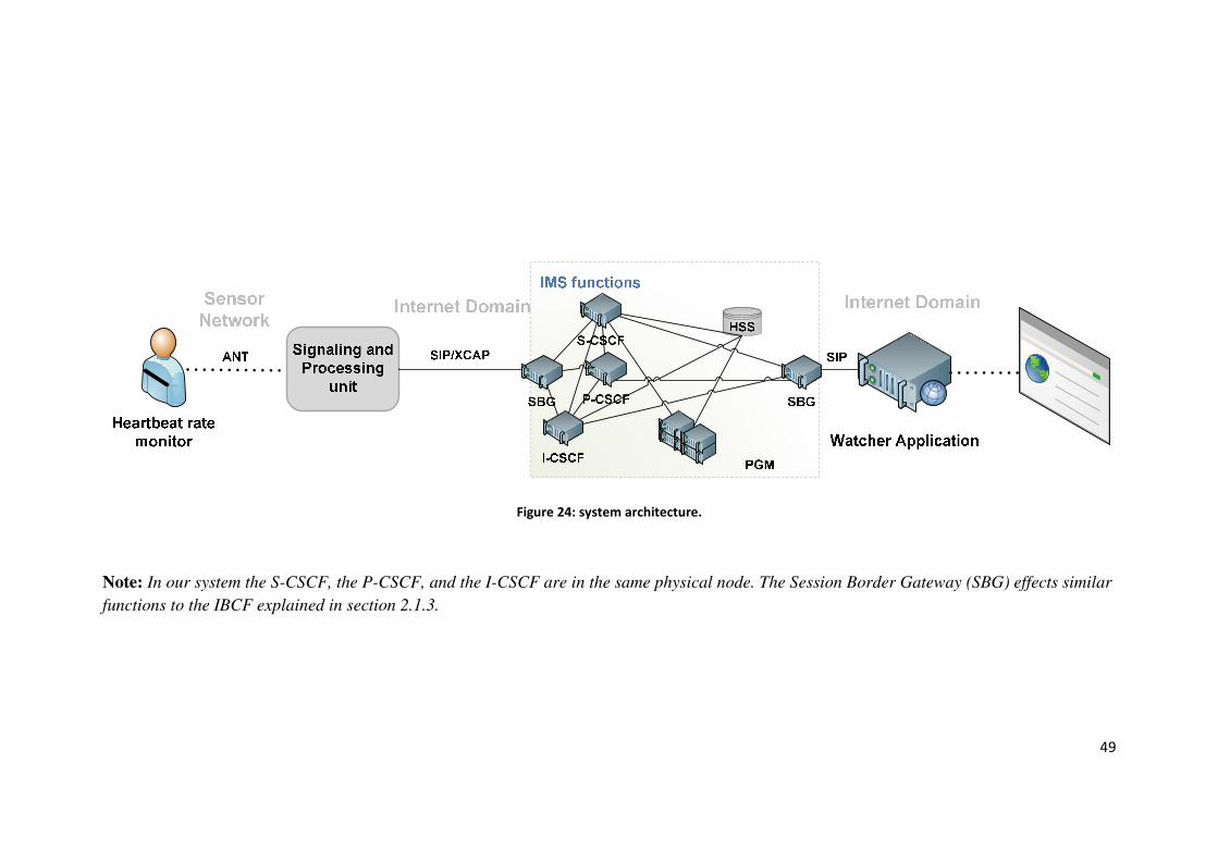
49
Figure 24: system architecture.
Note: In our system the S-CSCF, the P-CSCF, and the I-CSCF are in the same physical node. The Session Border Gateway (SBG) effects similar
functions to the IBCF explained in section 2.1.3.

50
4.2 Mobile solution
The mobile solution is intended to be used for outdoor sports activities such as running, cross
country skiing, biking, etc. The principal goal of this solution is to offer mobility.
In this alternative solution of the monitoring system, the SPU is formed by the All-in-one
(ANT-to-Bluetooth/SSI Bridge) module, a Bluetooth enabled mobile phone with internet
connectivity, and a software application that runs on top of the mobile phone (this application
requests and processes sensor data, and it also acts as a PUA). Figure 25 illustrates the mobile
SPU platform, with its interacting components and involved protocols.
Figure 25: SPU for mobile solution.
4.2.1 The mobile SPU’s signaling interaction
The mobile phone application (MPA) is the heart of the SPU platform. It is the MPA that
normally initiates the interaction within the SPU. Figure 26 show an example of how this
interaction might look. The different SPU components start to interact when the MPA
searches for and discovers the available Bluetooth services. If there are services available,
then a list of Bluetooth devices will be generated. The user will select the SPU Bluetooth
module from the list, then the MPA will create a serial port profile (SPP) connection with the
Bluetooth device (1). After this serial connection is established (3) the MPA registers with the
IMS network and subscribes to the presentity’s watcher list; this is done by a SIP REGISTER
(4) and a SIP SUBSCRIBE request (6) respectively. Later the application starts to query the
sensor for data. Every time the MPA queries the HRM for data, it sends SSI command
messages over the SPP connection (10), this messages are converted into the corresponding
ANT specific message by the All-in-one microprocessor. After this conversion process the
command messages are forwarded to the HRM via ANT radio technology (11). When the
HRM responds, the SPU receives an ANT message (12) converts it to an SSI message and
transmits this message to the MPA over the already established Bluetooth SPP connection.
Finally the MPA receives the SSI message (13) and interprets it as described in section 2.11.2.
HRM
IMS
ANT
SIP/XCAP
ANT
Bluetooth Mobile Phone
All-in-one SPU
Micro Proc. unit
Bluetooth SPP SSI

51
A valid message from the HRM for this solution is either a Query reply or a Sensor data
response. If the received messages contains sensor measurements, then the MPA generates a
PUBLISH request (14) that will be forwarded to the PGM via IMS. This PUBLISH request
contains the HRM data as a value field in the presence document. The MPA has additional
functionalities such as watcher list management (performed through XCAP)[43].
Note: Once the Bluetooth connection is established it remains open for as long as the session
lasts, the sequences numbered 10 to 15 in figure 26 are executed in a asynchronous cycle
(that is established by the delay of the 200 OK response of the PUBLISH request and
configurable sleep timer managed by the application), this cycle is executed for as long as the
user wants to publish his heartbeat rate. The sequences numbered 1 to 9 are mandatory
before the querying and publishing procedure begins, if one of this processes fails, then the
MPA must re-execute them.
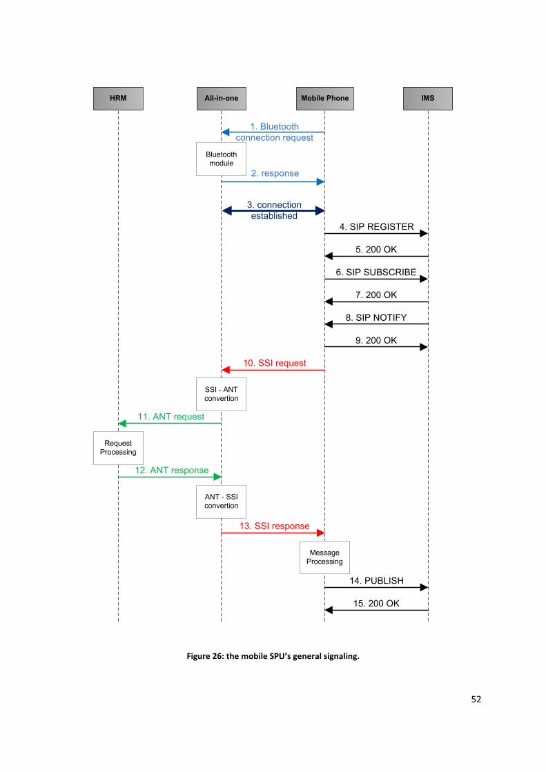
52
Mobile PhoneAll-in-one IMSHRM
1. Bluetooth
connection request
2. response
3. connection
established
Bluetooth
module
10. SSI request
SSI - ANT
convertion
11. ANT request
12. ANT response
Request
Processing
ANT - SSI
convertion
13. SSI response
4. SIP REGISTER
5. 200 OK
6. SIP SUBSCRIBE
7. 200 OK
8. SIP NOTIFY
9. 200 OK
14. PUBLISH
15. 200 OK
Message
Processing
Figure 26: the mobile SPU’s general signaling.
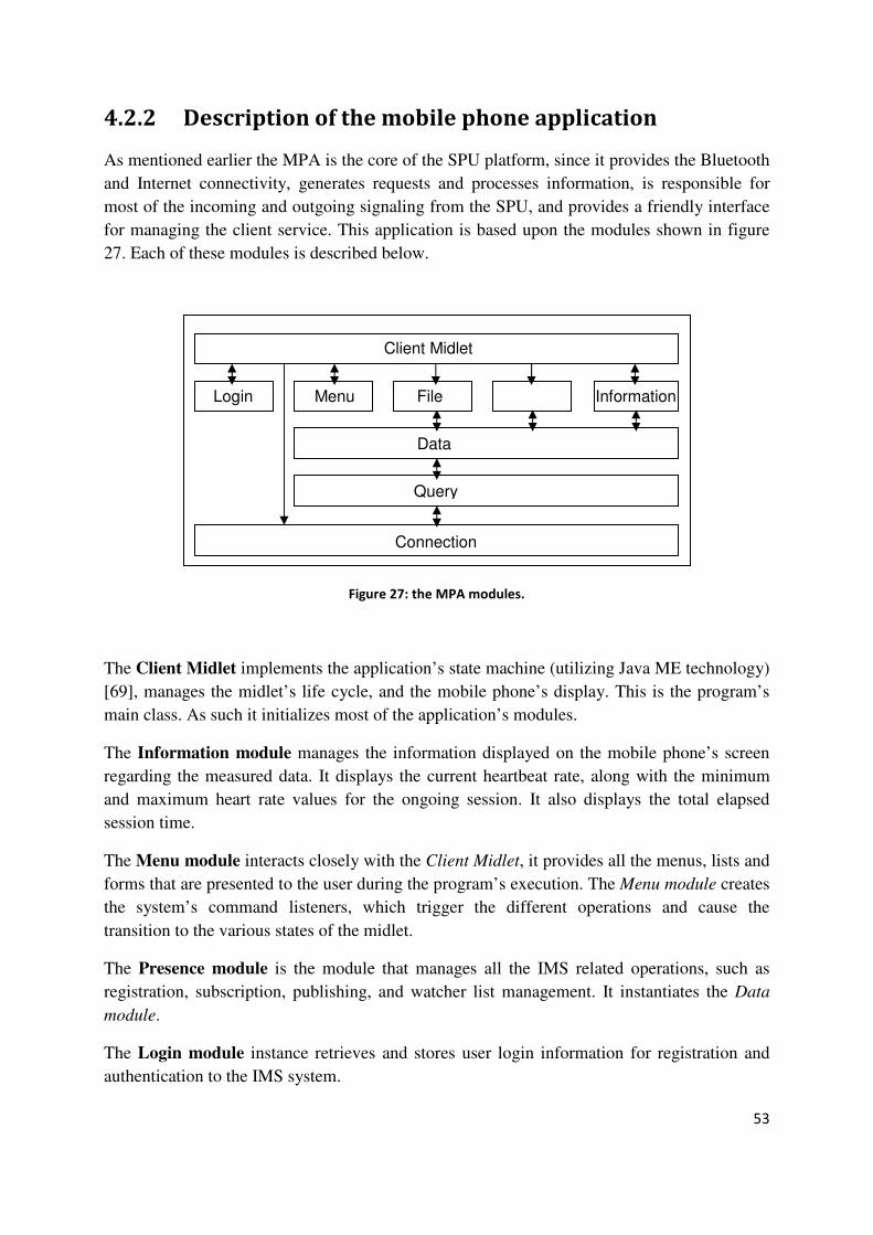
53
4.2.2 Description of the mobile phone application
As mentioned earlier the MPA is the core of the SPU platform, since it provides the Bluetooth
and Internet connectivity, generates requests and processes information, is responsible for
most of the incoming and outgoing signaling from the SPU, and provides a friendly interface
for managing the client service. This application is based upon the modules shown in figure
27. Each of these modules is described below.
Figure 27: the MPA modules.
The Client Midlet implements the application’s state machine (utilizing Java ME technology)
[69], manages the midlet’s life cycle, and the mobile phone’s display. This is the program’s
main class. As such it initializes most of the application’s modules.
The Information module manages the information displayed on the mobile phone’s screen
regarding the measured data. It displays the current heartbeat rate, along with the minimum
and maximum heart rate values for the ongoing session. It also displays the total elapsed
session time.
The Menu module interacts closely with the Client Midlet, it provides all the menus, lists and
forms that are presented to the user during the program’s execution. The Menu module creates
the system’s command listeners, which trigger the different operations and cause the
transition to the various states of the midlet.
The Presence module is the module that manages all the IMS related operations, such as
registration, subscription, publishing, and watcher list management. It instantiates the Data
module.
The Login module instance retrieves and stores user login information for registration and
authentication to the IMS system.
Presence
Connection
Client Midlet
Query
Data
Login File Menu Information
54
The File module stores sensor data locally in system for later use. This data can be transferred
to a computer and analyzed with other tools.
The Connection module manages the Bluetooth serial connection. It involves device
discovery, service search, connection setup, and connection closing.
The Query module manages the SSI command interaction. It generates and sends SSI
command messages via the Bluetooth SPP connection (note: it retrieves the connection
identifier from the Connection module), and it also processes the response messages content.
This module also decodes the SSI message’s Value measurement field (i.e., it performs the
decoding from floating point 32 to integer, this value was chosen to be truncated to integer,
just to have a nicer output).
The Data module instantiates the Query module to manage the query triggering and current
heart rate value. The Data module computes statistics about the minimum and maximum
heartbeat rate, as well as recording the total elapsed session time.
4.2.3 Execution on the MPA
In this subsection we will describe the complete execution sequence for the MPA. When the
users start the application they are prompt with an Execution Option menu, from which they
chose between storing data locally or publishing it on the web. If they chose to publish the
information, then the information will be sent to the PGM via IMS, and the PGM will make
the data available for other users. This process will be described from when the user runs the
program to the point where information is published to the PGM. This will involve all the
functions described in the previous subsection. Figure 28 shows the sequence diagram.
Following this figure all of the different steps are explained.

55
Menu InformationPresenceClient Login File ConnectionQuery
Seq. 1.
Seq. 2.
Seq. 3.
Seq. 4.
Seq. 5.
Seq. 6.1.
Seq. 6.2.
Seq. 7.
Seq. 8.1.
Data
Seq. 12.
Seq. 8.2. Seq. 8.3. Seq. 8.4.
Seq. 9.1. Seq. 9.2. Seq. 9.3.
Seq. 10.
Seq. 11.1. Seq. 11.2.
Figure 28: general sequence diagram for the MPA.
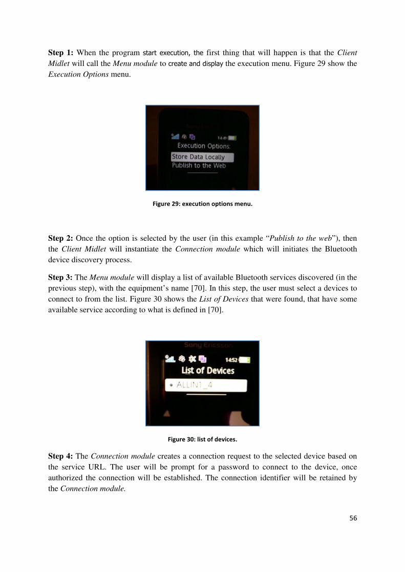
56
Step 1: When the program start execution, the first thing that will happen is that the Client
Midlet will call the Menu module to create and display the execution menu. Figure 29 show the
Execution Options menu.
Figure 29: execution options menu.
Step 2: Once the option is selected by the user (in this example “Publish to the web”), then
the Client Midlet will instantiate the Connection module which will initiates the Bluetooth
device discovery process.
Step 3: The Menu module will display a list of available Bluetooth services discovered (in the
previous step), with the equipment’s name [70]. In this step, the user must select a devices to
connect to from the list. Figure 30 shows the List of Devices that were found, that have some
available service according to what is defined in [70].
Figure 30: list of devices.
Step 4: The Connection module creates a connection request to the selected device based on
the service URL. The user will be prompt for a password to connect to the device, once
authorized the connection will be established. The connection identifier will be retained by
the Connection module.

57
Step 5: The Login module prompts the user for his or her IMS credentials, this information
will be used when registering with the IMS network.
Step 6: The IMS registration (in step Seq. 6.1.), and watcher list subscription (Seq. 6.2) are
executed. This is done by the Presence module, which accesses the data credentials stored by
the Login module in the phone’s persistent memory through a Recordstore operation [69].
Step 7: Once the previous process has completed successfully, then the Menu module changes
the present connection menu into a menu for viewing and sending HRM information.
Step 8: The Presence module instantiates the Data module, which calls the Query module
which uses the connection identifier, stored by the Connection manager to send and receive
messages from the HRM.
Step 9: The Presence module calls the Data module to trigger a query from the Query module
to retrieve the current HRM value. The Presence module receives the latest sensor data and
the related statistics from the Data module (these values can be accessed statically from the
other modules), and generates the PUBLISH request, which is sent via IMS.
Step 10: The File module stores the sensor data in a file together with the current time stamp.
Step 11: The Information module displays on the mobile phone’s screen the current measured
HRM value, and the minimum, and maximum values for the ongoing session, together with
the elapsed session time. Figure 31 shows the HRM information as displayed on a mobile
phone.
Figure 31: HRM Information displayed on a mobile phone.
Note: When a 200 OK is received in response to the PUBLISH request, then the steps from 9
to 11 will be re-executed. This will continue until the user decides to stop the application or
fail response is received. So far only 403 responses are handled (with a re-registering
operation).
Step 12: After terminating the execution of the program, the Presence module will unregister
from the IMS network by sending a REGISTER request with the Expires field equal to zero.

58
4.2.4 Hardware used in the mobile SPU
The mobile phone used in the implementation and testing of the prototype was a Sony
Ericsson W910i. This phone is Bluetooth enabled, with 1 GB of memory, and support for
GPRS, EDGE, UMTS, and HSDPA. The All-in-one module has a Bluetooth transceiver, an
ANT transceiver, a micro processing unit, and a rechargeable battery.
4.2.5 Tools used for developing the MPA
The tools used for developing the MPA will be briefly described in this section. We will begin
with the programming language and move on to the integrated development environment.
The Java Platform, Micro Edition (Java ME) was used for programming and is a collection
of technologies and specifications that provides a robust, flexible environment for building
applications that will run on mobile phones, PDAs, TV set-top boxes, printers, and other
embedded devices. Java ME includes flexible user interfaces, robust security, built-in network
protocols, and support for networked and offline applications that can be downloaded
dynamically. Applications based on Java ME are portable across many devices, while often
able to utilize a device's native capabilities.[71] In addition to the Java ME standard libraries,
we used an Ericsson early version of the JSR 281 [72] (developed within the scope of the
HiFive project [7]). This library provides a high-level API for IMS.
The integrated (program) development environment (IDE) used was the Eclipse Java IDE
version 3.3.1.1. This is an extensible open source development platform that is part of the
Eclipse community project. These projects are focused on creating a development platform,
runtime libraries, and application frameworks for building, deploying, and managing software
across the entire software lifecycle. [73] When developing Java ME applications it necessary
to install the Sun Java Wireless Toolkit for CLDC (we used version 2.5.2) [74]. This toolkit
is designed to facilitate development of wireless applications based on Java ME's Connected
Limited Device Configuration (CLDC) and Mobile Information Device Profile (MIDP). The
toolkit includes the relevant Java ME libraries, emulation environments, performance
optimization, and tuning features. This toolkit cannot be used as a standalone development
environment (as it does not include a text editor). In order to use the Eclipse Java IDE
together with Sun’s Java Wireless Toolkit it is necessary to install EclipseME version 1.7.9, a
plugin for Eclipse that helps developing Java ME MIDlets. This plugin connects the Sun Java
Wireless Toolkit to the Eclipse development environment, facilitating working with Java ME.
[75]
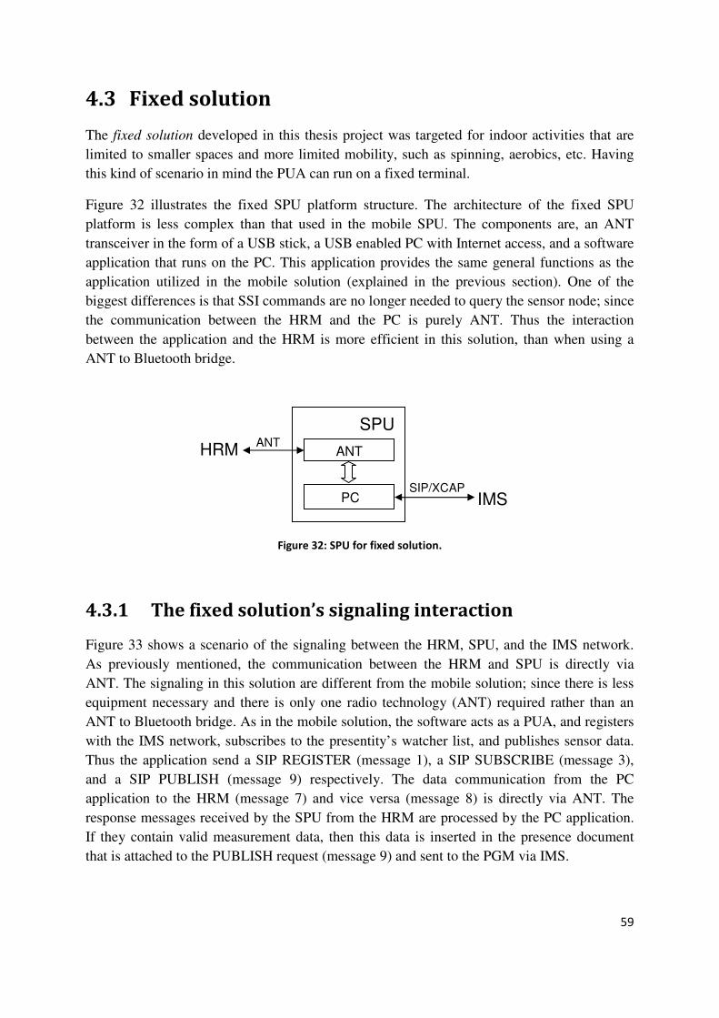
59
4.3 Fixed solution
The fixed solution developed in this thesis project was targeted for indoor activities that are
limited to smaller spaces and more limited mobility, such as spinning, aerobics, etc. Having
this kind of scenario in mind the PUA can run on a fixed terminal.
Figure 32 illustrates the fixed SPU platform structure. The architecture of the fixed SPU
platform is less complex than that used in the mobile SPU. The components are, an ANT
transceiver in the form of a USB stick, a USB enabled PC with Internet access, and a software
application that runs on the PC. This application provides the same general functions as the
application utilized in the mobile solution (explained in the previous section). One of the
biggest differences is that SSI commands are no longer needed to query the sensor node; since
the communication between the HRM and the PC is purely ANT. Thus the interaction
between the application and the HRM is more efficient in this solution, than when using a
ANT to Bluetooth bridge.
Figure 32: SPU for fixed solution.
4.3.1 The fixed solution’s signaling interaction
Figure 33 shows a scenario of the signaling between the HRM, SPU, and the IMS network.
As previously mentioned, the communication between the HRM and SPU is directly via
ANT. The signaling in this solution are different from the mobile solution; since there is less
equipment necessary and there is only one radio technology (ANT) required rather than an
ANT to Bluetooth bridge. As in the mobile solution, the software acts as a PUA, and registers
with the IMS network, subscribes to the presentity’s watcher list, and publishes sensor data.
Thus the application send a SIP REGISTER (message 1), a SIP SUBSCRIBE (message 3),
and a SIP PUBLISH (message 9) respectively. The data communication from the PC
application to the HRM (message 7) and vice versa (message 8) is directly via ANT. The
response messages received by the SPU from the HRM are processed by the PC application.
If they contain valid measurement data, then this data is inserted in the presence document
that is attached to the PUBLISH request (message 9) and sent to the PGM via IMS.
SPU
ANT
PC
HRM
IMS
ANT
SIP/XCAP

60
Figure 33: the fixed SPU’s general signaling.
4.3.2 Description of the Desktop application
The desktop application offers a GUI with several functions, among them user management,
data storage, a screen that displays the sensed data, minimums, maximums, and the total
elapsed time of each session. The application interacts with the HRM through a thin low level
layer module (Query module) written in C that uses the ANT API made by SUUNTO to
request and receive sensor data from the HRM. This low level module interacts with the J2SE
modules through the Java Native Interface (JNI). The presence related operations are the
same as in the mobile application. The desktop application registers with the IMS network
through a SIP REGISTER request, and then subscribes to a presentity’s watcher list with a
SIP SUBSCRIBE request. On each new sensed value the application publishes the data to the
PGM and stores the values into a file. This file can be retrieved by the user and used with
other tools. Figure 34 shows the application’s module structure. The functions of each module
are briefly described below.

61
Figure 34: desktop application’s module structure 3
The ANT API provides driver routines for interacting with the USB ANT transceiver. It also
provides methods for detecting ANT sensor units and for querying them.
The Query module uses the discovery and query methods present in the ANT API, to the
HRM based upon its sensor address (discovered by querying the broadcast address 0x3F),
then to request sensor information and measurement data from it.
The JNI module enables the J2SE methods to interact with the Query module that is written
in C.
The Users module administers the system users, basic data (specifically the information need
to login to the IMS network, such as Public User Identity, Private User Identity, and
password. These parameters are used to emulate the subscriber’s ISIM credentials, as today
there are no ISIM available in the market). Through this module a user's data can be added,
deleted, or edited. This module interacts only with the GUI.
The Files module stores the sensed data in a simple two column format (value/timestamp, the
timestamp is expressed as “yyyy-MM-dd HH:mm:ss.SS” format, which represents the time in
which the Data module got the heart rate value). Each new measured value the data is stored
to a file, transparently to the user. Before exiting or when starting a new measurement session
the user is asked via the GUI if they want to store the measured data. If not, then the
background processing of the file will not take place. The Files module interacts with both the
Data and GUI modules.
The Data module communicates with JNI in order to make the sensor values available to the
rest of the modules (GUI, Files, and Presence) in a cyclic operation, the sensor values are
kept in a static variable. This module also computes statistics, such as minimum and
maximum heart rate per session, as well as keeping track of the total elapsed time of a session.
The Presence module is the module that makes it possible for the application to connect to
the IMS network. This module implements the PUA related features: REGISTER,
Screen
ANT API
JNI
UsersPresence Data
GUI
Files
Query Module

62
SUBSCRIBE, PUBLISH, and administer watcher lists. Through this module the data is
published to the PGM via IMS. This module interacts with the GUI when the session is
initiated and ends, it receives the sensor data from the Data module and uses the user’s
credentials to register when it initialized.
The GUI module is the main class of the program. This module it interacts with all the higher
level modules and acts as a user interface for each one of them. The GUI offers user
administration menu, along with displaying the data and statistics related to the session. It also
provides a menu for retrieving and publishing the collected data.
4.3.3 Execution sequences of the desktop application
In this subsection, we will show the interaction between the different modules within the
application through an example. The purpose is to present their general functionalities.
When a user first runs the application, the first thing that he or she should do is to configure a
profile. This is done by selecting the User add option from the File menu or by right clicking
over the profiles tables and entering the requested data, after adding the user credentials the
system will store them persistently. This user profile will now be visible in the applications
display as a valid profile, which can now be used to connect with the IMS network. Figure 35
shows the desktop client and the Add user menu.
Figure 35: desktop application, adding user operation.
Provisioned user

63
When the user decides to initiate the measurement procedure, he or she must select a user
profile from the existing ones to begin a new session, then press the Start (session) button.
The IMS connection procedure will begin. When there is sensor data it will be displayed in
the visual information screen, and at the same time it will be published to the PGM via IMS.
Figure 36 shows the information displayed by the desktop client.
Figure 36: desktop application, publishing measurement information.
Note: This figure caption was taken right after lunch. I climb 5 stares to get back to my office.
When the user wishes to stop the measurements, the user presses the "Stop" button; then a
popup menu will query the user, to ask if they wish to store the session data permanently, if so
a file manager window will be shown and the user will be able to save the file as
user-name-date-starting-time-of-session.txt. Once the measurement session has stopped no
additional data is retrieved from the HRM nor is any data published. Figure 37 shows the
sequence diagram for this example, and each step in the sequence is described below.
Current heartbeat rate, minimum
and maximum measured values, and
the total elapsed session time
Shows the application’s status
Connected user
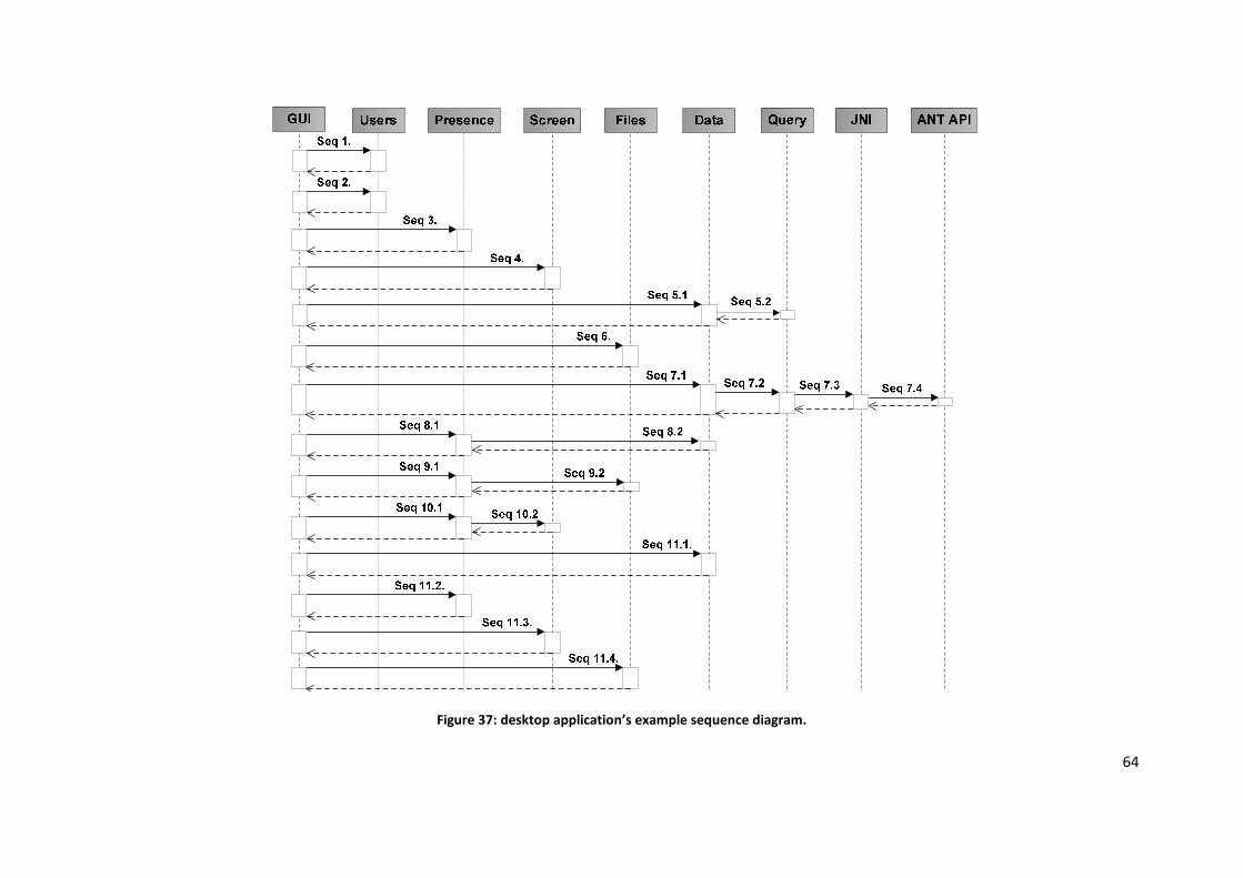
64
Figure 37: desktop application’s example sequence diagram.

65
Step 1: The GUI module creates an instance of the User module, and adds the user’s
credentials, then stores this user data in non-volatile storage, as a property file in the local file
system.
Step 2: After adding a new user, the GUI reloads the list of available user profiles with help
of the User module. Now the new user is displayed in the profile table.
Step 3: A user profile is selected from the list and the Start button is pressed to initiate the
session. The GUI reads the selected table field and extracts the name of the selected user
profile from there. With this data it initializes the Presence module. The presence module
performs the presentity’s registration and subscribes to its watcher list.
Step 4: The GUI creates an instance of the Screen module in which the measurement
information will later be displayed.
Step 5: The data measurement procedure is initiated. The GUI creates an instance of the Data
module which in his turn creates an instance of the JNI module.
Step 6: The GUI creates an instance of the Files module.
Step 7: The Data module performs measurement queries and stores the measurement value in
a local variable, updates the statistics (such as minimum, maximum measured values), and
records the total elapsed time of the session. After this the thread sleeps - awaiting another
measurement event.
Step 8: The Presence Module extracts the measured values along with the statistical data
from the Data module through a static method, then it generates and sends the PUBLISH
message with this information to the PGM via IMS. When it receives a 200 OK response, this
process sleeps for a configurable time period, this can be used to handle the frequency in
which the publish messages are sent, this time is additional to the response delay that is not
manageable.
Step 9: The Files module also retrieves the measured value and the timestamp from the Data
module, stores the data in a temporary session file as a value and timestamp; with a tab
between the values. Entries are stored with one line per measurement.
Step 10: The Screen module reads the data from the Data module and displays it on the
information screen.
Note: The Data and Presence processes are run by the GUI in different threads. The Files
and Screen modules are run by the same thread. First the Data module is initialized, and then
the Presence module, and finally the Files and the Screen module. These threads are
asynchronous to each other. The Presence and Files threads will assume there is new data
when the session’s timestamp, kept by the Data module has changed. This processes are
executed in a cycle.

66
Step 11: When the user presses the Stop session button, all processing stops, this includes the
Data, Presence, Files, and Screen modules.
Step 11.1: When the Data module receives the stop signal it will terminate the query process
and fall sleep.
Step 11.2: Upon a received stop signal the Presence module will sleep.
Step 11.3: The Screen module sleeps after receiving the stop signal.
Step 11.4: When the Files module receives the stop signal it will popup a menu querying,
allowing the user to store the session file, if so, then the user gets to name the previously
stored temporary file otherwise the temporary file is removed. Following this the module
sleeps.
4.3.4 Hardware used in the fixed SPU
A laptop computer, specifically a HP Compaq nv8240 was used as the SPU. This computer is
equipped with an Intel Pentium Mobile 2 GHz processor, 2 GB of RAM, and a USB master
interface. An ANT transceiver in the form of a USB stick was inserted into the computer's
USB socket.
4.3.5 Tools used for developing the desktop application
The tools used for developing the desktop application are different from the ones chosen for
the MPA, as both the needs and the hardware platform were different.
When developing the desktop application we used both C and J2SE version 1.5. The resulting
code in these two languages interacts through J2SE’s Java Native Interface (JNI) technology
[76]. C was used in the programming related to the ANT transceiver and HRM query
operations. J2SE was used for the remainder of the solution (i.e., for the user interface,
network operations related to SIP and XCAP, etc). In this solution did not use the IMS API as
none was available for this platform. Note that the API used in the mobile client was not
possible to use as it was built Java ME specific, which is not upward compatible with J2SE
(As the network, and connector classes, among others are defined in the javax.microedition.*
packet which is only available in Java ME). Instead we used the SIP API’s from JAIN-SIP
[77], an open-source project that provides a standard portable interface to share information
between SIP Clients and SIP Servers according to the RFC 3261 [20]. The JAIN-SIP
specifications can be found in the JSR 32 [78].
The programming environment used for developing the desktop application was the Netbeans
IDE version 6.1 [79]. This is an open-source IDE, with all the tools needed to create desktop,
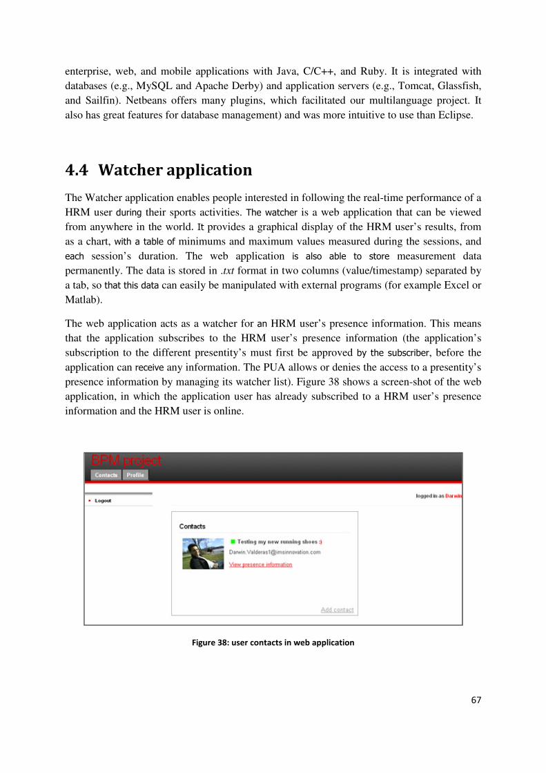
67
enterprise, web, and mobile applications with Java, C/C++, and Ruby. It is integrated with
databases (e.g., MySQL and Apache Derby) and application servers (e.g., Tomcat, Glassfish,
and Sailfin). Netbeans offers many plugins, which facilitated our multilanguage project. It
also has great features for database management) and was more intuitive to use than Eclipse.
4.4 Watcher application
The Watcher application enables people interested in following the real-time performance of a
HRM user during their sports activities. The watcher is a web application that can be viewed
from anywhere in the world. It provides a graphical display of the HRM user’s results, from
as a chart, with a table of minimums and maximum values measured during the sessions, and
each session’s duration. The web application is also able to store measurement data
permanently. The data is stored in .txt format in two columns (value/timestamp) separated by
a tab, so that this data can easily be manipulated with external programs (for example Excel or
Matlab).
The web application acts as a watcher for an HRM user’s presence information. This means
that the application subscribes to the HRM user’s presence information (the application’s
subscription to the different presentity’s must first be approved by the subscriber, before the
application can receive any information. The PUA allows or denies the access to a presentity’s
presence information by managing its watcher list). Figure 38 shows a screen-shot of the web
application, in which the application user has already subscribed to a HRM user’s presence
information and the HRM user is online.
Figure 38: user contacts in web application
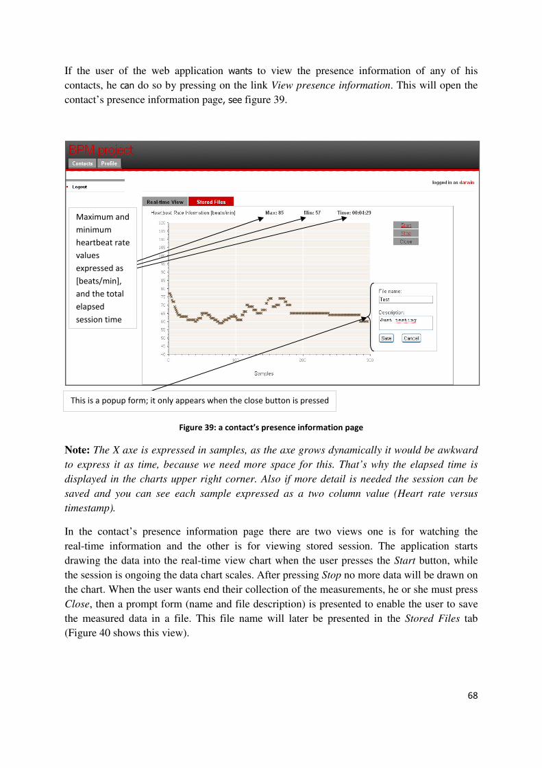
68
If the user of the web application wants to view the presence information of any of his
contacts, he can do so by pressing on the link View presence information. This will open the
contact’s presence information page, see figure 39.
Figure 39: a contact’s presence information page
Note: The X axe is expressed in samples, as the axe grows dynamically it would be awkward
to express it as time, because we need more space for this. That’s why the elapsed time is
displayed in the charts upper right corner. Also if more detail is needed the session can be
saved and you can see each sample expressed as a two column value (Heart rate versus
timestamp).
In the contact’s presence information page there are two views one is for watching the
real-time information and the other is for viewing stored session. The application starts
drawing the data into the real-time view chart when the user presses the Start button, while
the session is ongoing the data chart scales. After pressing Stop no more data will be drawn on
the chart. When the user wants end their collection of the measurements, he or she must press
Close, then a prompt form (name and file description) is presented to enable the user to save
the measured data in a file. This file name will later be presented in the Stored Files tab
(Figure 40 shows this view).
This is a popup form; it only appears when the close button is pressed
Maximum and
minimum
heartbeat rate
values
expressed as
[beats/min],
and the total
elapsed
session time

69
Figure 40: Stored Files tab in the contact’s presence information page
4.4.1 The Watcher application’s signaling interaction
The watcher application’s signaling uses only SIP, it registers with the IMS network using a
SIP REGISTER request, and subscribes to a HRM user’s presence information with the PGM
using a SIP SUBSCRIBE request. Each time the presence information is updated the PGM
will notify it of changes through a SIP NOTIFY request. Figure 41 shows the signaling
process in which the watcher application is involved.
The watcher application sends a SIP REGISTER to the SBG, this forwards it to the S-CSCF
who must authenticate the user, for this the S-CSCF communicates with the HSS to get the
watchers credentials. Once the watcher is authenticated, then the S-CSCF replies with an 200
OK (messages numbered 1 to 6).
When the watcher subscribes to the presentity’s presence information it sends a SIP
SUBSCRIBE request to the SBG which routes the request to the S-CSCF, which in turn
forwards it to the PGM, the PGM adds the presentity to the watcher’s presentity list and sends
back a 200 OK (this process includes the messages numbered 7 to 12).
Before the watcher application starts receiving any NOTIFY requests from the PGM, the
presentity’s PUA must allow the watcher’s subscription. Once the watcher is authorized it will
start receiving notifies (this sequence includes the authorization process; messages numbered
13 to 18).

70
Watcher HSSSBG
1. REGISTER
S-CSCF
2. REGISTER
PGM
3. DIAMETER
4. DIAMETER
5. 200 OK
6. 200 OK
7. SUBSCRIBE
8. SUBSCRIBE
9. SUBSCRIBE
Authorization
process
10. 200 OK
11. 200 OK
12. 200 OK
13. NOTIFY
14. NOTIFY
15. NOTIFY
16. 200 OK
17. 200 OK
18. 200 OK
Figure 41: watcher application’s signaling interaction
4.4.2 Description of the watcher application
In this section we briefly explain the functionalities of each of the modules involved in the
watcher application and their interaction. Figure 42 shows the modules that forms the web
application.
Figure 42: watcher application modules
User Presence Data
Web Interface
Files

71
The Web interface gives the application user a means to follow the performance of an athlete
during their sports activity. Using this system a user can access several different functions,
such as subscription to the HRM user’s presence information, view in real-time data coming
from an HRM user's PUA. The web interface enables the viewed data to be stored into files
for later analysis.
The User module handles the data to be presented to the application user and the information
about their contacts. This module administers three database tables: one for storing the
application user’s information, the second to store the user’s contact information, and the
third to map the users to their contacts (this table is use to not have redundant contact
information, because several users can have the same contact). This module handles all the
queries related to these tables.
The Data module handles all the data related to the measurements, its statistical data, and
total elapsed session time. The measured values are stored in an array list together with their
timestamp. The statistical data is kept in static variables.
The Files module manages the permanent data storage and the downloading processes (which
includes generating a file from the data stored in the database, and makes it available for the
user). This module handles all the database queries related to stored data. When storing the
measured data, the Files module must transforms the array kept by the Data module into
binary data, before storing it to a database table, and for downloading the data it must convert
it back to String format to stream the content as a file.
Note: The data is stored as binary fields in the database tables because the application has
no write permission in the servers file system, the only persistent storage available are the
database tables.
The Presence module is built on top of the HiFive [7] IMS API. This module generates all
the SIP requests performed by the watcher application and receives all the responses. Based
on these responses this module takes various actions, such as calling the Data module for
example, to store statistical data.
4.4.3 Execution sequences of the watcher application
In this section we will describe the interaction between the application modules, through an
example:
a user logs in to the system and wishes to view the presence information of one of his
contacts, so he presses the View presence information link. Once he or she has reached the
contact’s personal page, he presses the Start button to view the Real-time chart, after some
time the user wishes to end the data displaying, so he presses Close, he saves the data with a
name and a description (the measured data is save in a database table as binary data), to be
able to identify it later. Later the user downloads the data to analyze it using Matlab in a PC,
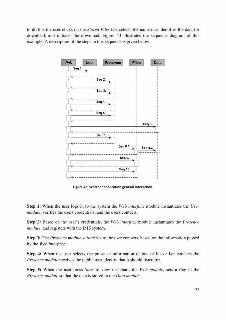
72
to do this the user clicks on the Stored Files tab, selects the name that identifies the data for
download, and initiates the download. Figure 43 illustrates the sequence diagram of this
example. A description of the steps in this sequence is given below.
Figure 43: Watcher application general interaction.
Step 1: When the user logs in to the system the Web interface module instantiates the User
module, verifies the users credentials, and the users contacts.
Step 2: Based on the user’s credentials, the Web interface module instantiates the Presence
module, and registers with the IMS system.
Step 3: The Presence module subscribes to the user contacts, based on the information passed
by the Web interface.
Step 4: When the user selects the presence information of one of his or her contacts the
Presence module receives the public user identity that it should listen for.
Step 5: When the user press Start to view the chart, the Web module, sets a flag in the
Presence module so that the data is stored in the Data module.
73
Step 6: The Web module starts to pull data from the Data module, through an Ajax module
called Prototype [80] that permits the generation of a real-time chart without having to refresh
the browser.
Step 7: When the user press the Stop button, the Web module, resets the flag in the Presence
module, so no more data is stored by the Data module. No more data pulling is performed.
Step 8: After pressing Close and save, the Web module performs a save data operation using
the Files module, which in turn must interact with the Data module to retrieve the measured
values and convert them into binary and store them in a database table, with the attributes of
name and description (together with other parameters such user’s ID, contact’s ID and
timestamp) entered by the user.
Step 9: When the user presses the Stored Files tab, the Web module queries the database table
through the Files modules, for all measurement sessions stored in the system available to this
user and contact, generating a list of these measurement sessions (files).
Step 10: The user chooses a file to download. The Web module, through the Files modules converts the binary data into a file in tab separated columns (.txt format) when downloading.
4.4.4 Tools used for developing the watcher application
The development environment was Neatbeans [79]. This tool was chosen rather than Eclipse,
because it has good database support and it is also well integrated with the Sailfin application
server [81]. Sailfin is being used as the AS in the production platform. Neatbeans facilitates the
deployment of the application, this helps in debugging. The database used for this project was
MySQL version 5.0.51b of the Community Server [82].
The programming technologies and languages used for developing the application, were Java
Enterprise Edition (Java EE), Prototype, Dojo, JavaScript, and SQL.
- Java EE version 5.0 was the base technology for developing the application. The IMS
API’s used in the Presence module are solely Java EE [7].
- Prototype [80] is a JavaScript framework that facilitates the development of dynamic
web applications. Prototype was used in the data pulling to generate the chart and the
statistics where output from the Java EE classes running on the server.
- Dojo [83] is also a JavaScript toolkit that has a lot of great features. In this
implementation we used dojo to generate the dynamic chart.
- We used SQL, to query the database from the java classes.
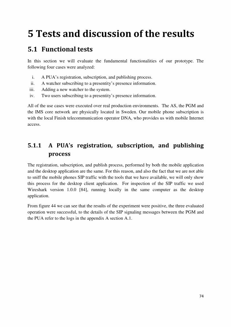
74
5 Tests and discussion of the results
5.1 Functional tests
In this section we will evaluate the fundamental functionalities of our prototype. The
following four cases were analyzed:
i. A PUA’s registration, subscription, and publishing process.
ii. A watcher subscribing to a presentity’s presence information.
iii. Adding a new watcher to the system.
iv. Two users subscribing to a presentity’s presence information.
All of the use cases were executed over real production environments. The AS, the PGM and
the IMS core network are physically located in Sweden. Our mobile phone subscription is
with the local Finish telecommunication operator DNA, who provides us with mobile Internet
access.
5.1.1 A PUA’s registration, subscription, and publishing
process
The registration, subscription, and publish process, performed by both the mobile application
and the desktop application are the same. For this reason, and also the fact that we are not able
to sniff the mobile phones SIP traffic with the tools that we have available, we will only show
this process for the desktop client application. For inspection of the SIP traffic we used
Wireshark version 1.0.0 [84], running locally in the same computer as the desktop
application.
From figure 44 we can see that the results of the experiment were positive, the three evaluated
operation were successful, to the details of the SIP signaling messages between the PGM and
the PUA refer to the logs in the appendix A section A.1.

75
Figure 44: registration, subscription, and publish process.
The registration process involves authentication and authorization, this is described in
section 2.5.2. In the subscription process that we are pointing out here is when the PUA
subscribes to his watcher list, to be able to get notifications to changes in the watcher list. The
publication process involves sending the actual heartbeat rate, minimum, maximum, and total
elapsed session time which are embedded in the note field as shown in figure 45. No new xml
schemas (this will be done in the future work) were defined for this matter.
<pdm:note>Heartbeat_rate;Minimum;Maximum;Session_time</pdm:note>
Figure 45: format for sending the HRM data.
5.1.2 A watcher subscribing to a presentity’s presence
information
For the watcher to be able to access a presentity’s presence information he must first
subscribe to it and get authorization from the presentity’s PUA. In this evaluation scenario our
watcher is already authorized. In the coming example, when showing the creation of a new
watcher we will show what happens when a watcher subscribes for the first time a to a
presentity’s presence information.
Registration Subscription Publishing

76
When doing this test we used the mobile application as the PUA. The data gathered is from
the AS. The traffic that will be shown is from the interaction between the watcher application
and the PGM.
From figure 46 we can see that the subscription went fine and that the watcher starts to
receive notify messages after getting the 200 OK response of the SUBSCRIBE request. To
view the SIP signaling logs related to this transaction refer to section A.2 in the appendix A.
Figure 46: watcher subscribing to a presentity’s presence information.
Description of the process: a watcher subscribes to a presentity’s presence information. The
watcher is then updated with the presentity’s most recent presence information (if any
available). After a while the presentity’s PUA gets online, and started to publish its HRM
information, the PGM notifies the watcher in every new update of the presence information
related to his subscription.
Subscription Notifications
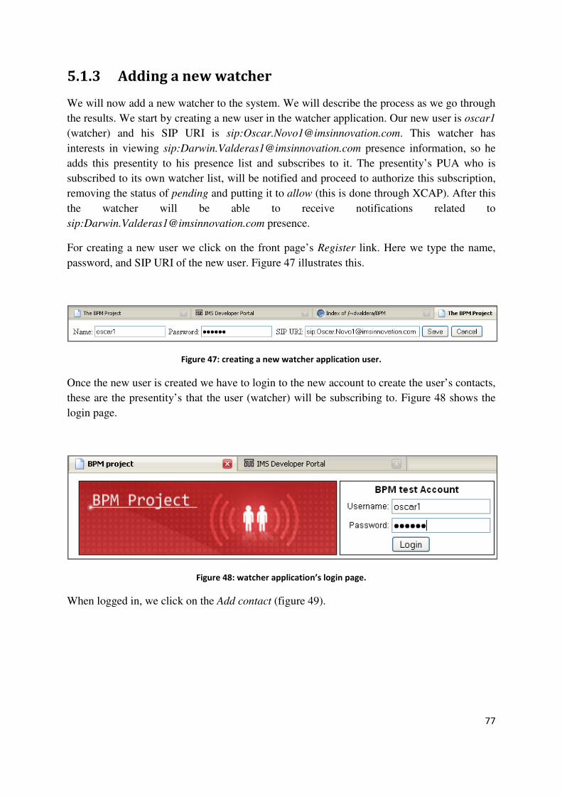
77
5.1.3 Adding a new watcher
We will now add a new watcher to the system. We will describe the process as we go through
the results. We start by creating a new user in the watcher application. Our new user is oscar1
(watcher) and his SIP URI is sip:[email protected]. This watcher has
interests in viewing sip:[email protected] presence information, so he
adds this presentity to his presence list and subscribes to it. The presentity’s PUA who is
subscribed to its own watcher list, will be notified and proceed to authorize this subscription,
removing the status of pending and putting it to allow (this is done through XCAP). After this
the watcher will be able to receive notifications related to
sip:[email protected] presence.
For creating a new user we click on the front page’s Register link. Here we type the name,
password, and SIP URI of the new user. Figure 47 illustrates this.
Figure 47: creating a new watcher application user.
Once the new user is created we have to login to the new account to create the user’s contacts,
these are the presentity’s that the user (watcher) will be subscribing to. Figure 48 shows the
login page.
Figure 48: watcher application’s login page.
When logged in, we click on the Add contact (figure 49).

78
Figure 49: Contacts page.
When adding a new contact, only the name by which we will identify the contact and a valid
SIP URI (as in figure 50) are needed.
Figure 50: adding a new contact.
Once the contact is provisioned it will be visible in the Contacts page as shown in figure 51.
This contact is now also added to the user’s presence list (this presentity is perceived as
offline right now, that’s why the red square is on. Once notify messages starts to come this
square will change to green in sign of online).
Figure 51: new contact.
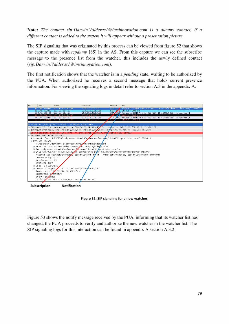
79
Note: The contact sip:[email protected] is a dummy contact, if a
different contact is added to the system it will appear without a presentation picture.
The SIP signaling that was originated by this process can be viewed from figure 52 that shows
the capture made with tcpdump [85] in the AS. From this capture we can see the subscribe
message to the presence list from the watcher, this includes the newly defined contact
(sip:[email protected]).
The first notification shows that the watcher is in a pending state, waiting to be authorized by
the PUA. When authorized he receives a second message that holds current presence
information. For viewing the signaling logs in detail refer to section A.3 in the appendix A.
Figure 52: SIP signaling for a new watcher.
Figure 53 shows the notify message received by the PUA, informing that its watcher list has
changed, the PUA proceeds to verify and authorize the new watcher in the watcher list. The
SIP signaling logs for this interaction can be found in appendix A section A.3.2
Subscription Notification

80
Figure 53: notification for changes in a watcher list.
5.1.4 Two watchers subscribing to the same HRM user’s
presence information
In this case we will show that the system is capable of handling more than one watcher at the
same time. Two watchers sip:[email protected] (watcher1) and
sip:[email protected] (watcher2) will be subscribing to
sip:[email protected] presence information.
Note: the system that we are using for running our prototype is a real production system, so
each user has to be provisioned in the HSS (we have only 4 URI’s that have been provisioned
for testing), that’s why we only used two watchers and not more for this testing.
When executing this evaluation test we used the desktop client application as the PUA, and
run Wireshark on the same computer to view the outgoing SIP PUBLISH requests and
compare them with the ones captured in the AS with tcpdump in .pcap format compatible
with Wireshark.
Evaluation test description: first the two watchers subscribed to the presentity’s
(sip:[email protected]) presence information by adding it to their
presence list and subscribing to the list. After the subscription, the watchers are notified with
status of the presentity’s in the presence list. Some seconds later
sip:[email protected] registers, and later he starts to send HRM
information to the PGM. The PGM then notifies all the authorized watchers with
Watcher list notification

81
sip:[email protected] presence information updates. Figure 54 shows
the data capture taken from the AS, the SIP signaling logs can be found in the appendix A
section A.4.
Figure 54: two watcher’s subscribing to the same presentity’s presence information.
Figure 55 shows the publish messages sent by the desktop client application to the PGM, who
will later notify the subscribed users about the new presence information. The SIP signaling
logs related to these publish operation from the client and the notifications received by the
watchers due to these (publish messages) can be found in appendix A section A.4.2.
Watcher1 subscription process Watcher2 subscription process
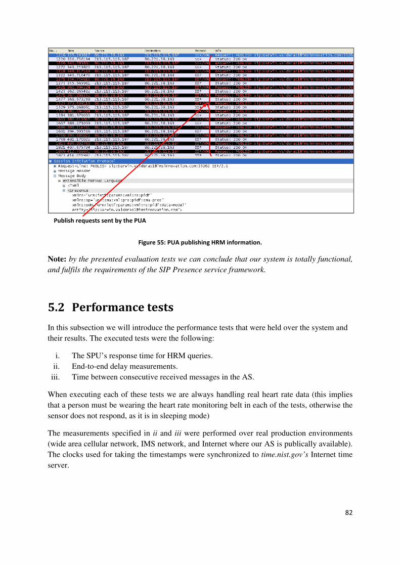
82
Figure 55: PUA publishing HRM information.
Note: by the presented evaluation tests we can conclude that our system is totally functional,
and fulfils the requirements of the SIP Presence service framework.
5.2 Performance tests
In this subsection we will introduce the performance tests that were held over the system and
their results. The executed tests were the following:
i. The SPU’s response time for HRM queries.
ii. End-to-end delay measurements.
iii. Time between consecutive received messages in the AS.
When executing each of these tests we are always handling real heart rate data (this implies
that a person must be wearing the heart rate monitoring belt in each of the tests, otherwise the
sensor does not respond, as it is in sleeping mode)
The measurements specified in ii and iii were performed over real production environments
(wide area cellular network, IMS network, and Internet where our AS is publically available).
The clocks used for taking the timestamps were synchronized to time.nist.gov’s Internet time
server.
Publish requests sent by the PUA

83
5.2.1 The SPU’s response time for HRM queries
These tests were performed over the two exiting SPUs’ (the mobile alternative that was
introduced in section 4.2 (figure 25) and the fixed solution showed in section 4.3). The test
procedure was to generate a Request Sensor Data query from the application and wait for a
valid response. A timestamp was taken before executing the query and when getting the
response.
From figure 56 we can view the result that was obtained when measuring the response time of
the mobile SPU for HRM queries.
Figure 56: the SPU’s response time for HRM queries – Mobile solution.
The resulting mean was 171,3389 milliseconds, this is 71,3389 milliseconds above the value
of 100 milliseconds replied from the sensor node (in section 2.11.2, figure 19), this means that
the All-in-one module is adding an extra delay of 71,3389 milliseconds in average to the
maximum expected HRM response time.
Figure 57 shows the result of the measurements taken from the fixed SPU for HRM queries.
mean = 171.3389

84
Figure 57: the SPU’s response time for HRM queries – Fixed solution.
What we can notice immediately from this figure is that the average and maximum are below
the Delay value obtained in section 2.11.2, figure 19. This can mean that the chipset vendors
have put an offset to assure the system developers that the sensor chipset will work and is able
to respond to a sample (processing) rate higher than 100 milliseconds.
5.2.2 End-to-end delay measurements
By measuring the end-to.end delay we can estimate the period of time that it will take for the
collected sensor data to be available for the end user.
The measurement process consisted in taking two timestamps, one right before acquiring the
sensor data (heartbeat rate) and the second when the message was received by the application,
resident in the AS. The period is obtained through a simple subtraction operation between the
two timestamps.
Figure 58 illustrates the end-to-end delay obtained for the mobile solution and figure 59 the
measured time for the fixed solution.
mean = 66.2806

85
Figure 58: end-to-end delay – Mobile solution.
Figure 59: end-to-end delay – Fixed solution.
The mean value for these two measurements is beyond the expected (a mean bellow of 500
ms would be suitable for this system, that doesn’t have a high frequency rate), but on the
mean = 2372
mean = 1386

86
other hand this is the first time any performance testing has been done to the system. This can
be seen as a starting point for performance tuning.
This project is still at an early stage and many improvements can be done, and this is
definitively a good moment for evaluating the prototype and review goals, to see how to go
ahead. Discuss if a real-time solution is this is still one the goals the final goals, if so other
protocols (as those mentioned section 2.7) should been considered as a valid option to follow,
due to the fact that the Presence service framework is not optimized yet, for handling
real-time communication.
5.2.3 Time period between consecutive messages received
by the AS
This process consisted in taking the time difference between two consecutive messages
received by the application running in the AS. These measurements will give us an idea on
how the users (of the watcher application) perception can be. This data will also give us an
additional input to improve the performance of our solution.
Figure 60 illustrates the time computed for the mobile solution and figure 61 shows the time
calculated for the fixed solution.
Figure 60: time between two consecutive messages received in the AS – Mobile solution.
mean = 1829

87
Figure 61: time between two consecutive messages received in the AS – Fixed solution.
By comparing the results of the two solutions, we can see that the fixed alternative is much
faster. The fixed solution’s measured time between consecutives messages is totally
acceptable. The only delay that the user might perceive, is the one caused by the initial
message (end-to-end delay, mean=1386 [ms]), but after that, the messages will only be space
in time by ~315 [ms], this is almost real-time for the heart rate frequency, as far as it doesn’t
exceed a pace of 180 [beats/min]. The mobile solution is as we expect slower than the fixed
solution. Much of this delay has to do with the way cellular networks [87] handles IP packets,
because once the packets accesses the fixed IP network the path is more or less the same, and
here there shouldn’t be a visible difference in delay between both of the solutions.
mean = 315.5

88
Conclusions and future work
6.1 Conclusions
In this thesis project we have developed two end-to-end systems (described in chapter 4) that
are able to interact with a sensor unit (heart rate monitor), and publish the information
collected from it to a Presence server (PGM), who redistributes this information to different
watchers that are subscribed to it.
6.1.1 General advantages and disadvantages
Advantages: the general solution offers data sharing, and almost real-time communication
(see section 5.2) between the sensor network and the end users. The system is built on top of
the IMS infrastructure, which has the potential to support a very large variety of devices and a
large number of services giving. This gives the system interesting interaction possibilities.
Another interesting feature is that the system uses the SIP Presence service, so it should be
fairly easy to incorporate it to other communication services or to add new functionalities.
Disadvantages: the mayor problem with this solution is related to one of its strengthen
points, this is the use of the Presence service frame work which is not optimize for handling
truly real-time traffic, although in the fixed solution this delays are not critical and they are
most of the time unperceivable, but in the mobile solution the delay is much bigger and
perceivable if we are expecting a real-time service.
Note: For a more accurate real-time solution the usage of other protocols is needed (as
analyzed in section 2.7), but this means a more complex solution.
6.1.2 Mobile solution
Advantages: the mayor advantage of this solution is the mobility and flexibility offer by its
platform. As the mobile application is programmed over Java ME it is portable to any Java
ME enabled phone with Bluetooth, today a large number of phones has these features.
Disadvantage: the mobile solution’s user terminal has limited processing power, low
bandwidth Internet connectivity, and higher delays (as showed in section 5.2) in the
interaction between the SPU and the HRM due to the All-in-one module.

89
6.1.3 Fixed solution
Advantages: the fixed solution offers almost real-time communication. The user terminal can
be plugged to a high speed Internet access, a USB ANT transceiver is used to interact directly
with the HRM. The application is run over a much more powerful platform. This system
compared to the mobile solution improves considerably the sensor network response time and
the end-to-end delay (PUA-watcher).
Disadvantages: its principal weakness is its lack of mobility, but on the other hand this was
its purpose.
6.1.4 Watcher application
Advantages: it possible to have access to numerous presentities presence information in
almost real-time, administer presentities, and store information related to each of them.
Disadvantages: the watcher application can be a bit processor demanding for both the client
host and the server, if the data pulling is configured for a too short period of time (less than a
second).
6.2 Future work
The future work for this project has already started, as we are integrating more sensors to the
system. We are adding an additional feature to the application so it can interact with a speed
sensor for runners (known as a foot POD [86]), and at a later stage we will make the fixed
solution capable of interacting with several heart rate monitors at foot-pods at the same time.
A location (cell or GPS based) module for the mobile application has also been brought up, as
well as adding push-to-talk functionalities, but this last alternative has only been mentioned in
informal meetings. Besides these new features, that we pretend to add to the system, there is
still much to optimize, as the system is at a very immature state, many things can be
improved, such as the design, performance, and hardware components (e.g. All-in-one
module). The watcher application should also provide richer information, handle more data,
and it should also offer a communication channel for interacting with the athlete, e.g. SMS or
push-to-talk. The community concept implemented in Runner+ [8] has also very interesting
features that are worth a thought.
90
References
[1] GSM World. Global GSM and 3GSM Mobile Connections. [Online] [Cited: April 5,
2008] http://www.gsmworld.com/index.shtml.
[2] Internet World Stats. Internet usages statistics: The Internet big picture - World
Internet users and population stats. [Online] [Cited: April 5, 2008]
http://www.internetworldstats.com/stats.htm.
[3] The NPD Group. Children are becoming exposed to and adopting electronic devices
at earlier ages. [Online] [Cited: May 18, 2008]
http://www.npd.com/press/releases/press_070605.html.
[4] ISWC. International Symposium on Wearable Computers. [Online] [Cited: May 18,
2008] http://www.iswc.net.
[5] BSN. International Workshop on Wearable and Implantable Body Sensor Networks.
[Online] [Cited: May 18, 2008] http://vip.doc.ic.ac.uk/bsn/m621.html.
[6] MyHeart. MyHeart. [Online] [Cited: May 10, 2008] http://www.hitech-
projects.com/euprojects/myheart/home.html.
[7] Ericsson. IMS innovation. [Online] [Cited: May 24, 2008]
https://as.imsinnovation.com.
[8] X7 Media. Runner+. [Online] [Cited: October 7, 2008] http://www.runnerplus.com.
[9] G. Camarillo, and M A. Garcia-Martin. The 3G IP Multimedia Subsystem: Merging
the Internet and the cellular worlds, Second edition. John Wiley & Sons Ltd, 2006.
978-0-470-01818-7.
[10] Open Mobile Alliance. About the Open Mobile Alliance. [Online] [Cited: April 12,
2008] http://www.openmobilealliance.org/AboutOMA/Default.aspx
[11] Light Reading. Lucent, Telefónica Team on IPTV. [Online] [Cited: July 20, 2008]
http://www.lightreading.com/document.asp?doc_id=92833.
[12] Multichannel news. IPTV with a Spanish Accent. [Online] [Cited: July 20, 2008]
http://www.multichannel.com/article/CA6381141.html.
[13] Com Hem. Com Hem först i Sverige med IMS i kommersiell drift. [Online] [Cited:
July 20, 2008] www.comhem.se/press/Com_Hem_IMS_071024.pdf.
[14] 3GPP. TS 24.147 - Conferencing using the IP Multimedia (IM) Core Network (CN)
subsystem, Release 7. 3rd Generation Partnership Project (3GPP), June 2008.
[15] ENTEL PCS. Push to Talk. [Online] [Cited: September 12, 2008]
http://www.entelpcsempresas.cl/productos_servicios/push_to_talk/index.iws.
[16] M. Poikselka, A. Niemi, H. Khartabil, and G. Mayer. The IMS: IP Multimedia
Concepts and Services, 2nd Edition. s.l. : John Wiley & Sons Ltd, January 2006. 978-
0-470-01906-1.
[17] 3GPP. TS 23.002 - Network Architecture, Release 7. 3rd Generation Partnership
Project (3GPP), March 2006.
[18] 3GPP. TS 23.228, IP Multimedia Subsystem (IMS), Release 8. 3rd Generation
Partnership Project (3GPP), June 2008.
91
[19] 3GPP. TS 29.278, Customized Application for Mobile network Enhanced Logic
(CAMEL)-CAMEL Application Part (CAP) specification for IP Multimedia
Subsystems (IMS), Release 7. 3rd Generation Partnership Project (3GPP), December
2005.
[20] J. Rosenberg , H. Schulzrinne, G. Camarillo, A. Johnston, J. Peterson, R. Sparks,
M. Handley, and E. Schooler. SIP: Session Initiation Protocol, Request for
Comments: 3261. IETF, June 2002.
[21] J. Peterson. S/MIME Advanced Encryption Standard (AES) Requirement for the
Session Initiation Protocol (SIP), Request for Comments: 3853. IETF, July 2004.
[22] R. Sparks. Actions Addressing Identified Issues with the Session Initiation Protocol's
(SIP) Non-INVITE Transaction, Request for Comments: 4320. IETF, January 2006.
[23] K. Zeilenga. Lightweight Directory Access Protocol (LDAP): Technical Specification
Road Map, Request for Comments: 4510. IETF, June 2006.
[24] M. Handley, V. Jacobson, and C. Perkins. Session Description Protocol (SDP).
Request for Comments: 4566. IETF, July 2006.
[25] H. Schulzrinne, S. Casner, R. Frederick, and V. Jacobson. RTP: A Transport
Protocol for Real-Time Applications. Request for Comments: 3550. IETF, July 2003.
[26] X. Yi. Adaptive Wireless Multimedia Services. Wireless Center, KTH, May 2006.
[27] M. Baugher, D. McGrew, M. Naslund, E. Carrara, and K. Norrman. The Secure
Real-time Transport Protocol (SRTP), Request for Comments: 3711. IETF, March
2004.
[28] E.Carrara. Security for IP Multimedia Applications over Heterogeneous Networks.
[Online] [Cited: September 12, 2008] http://web.it.kth.se/~carrara/lic.pdf.
[29] P. Calhoun, J. Loughney, E. Guttman, G. Zorn, and J. Arkko. Diameter Base
Protocol, Request for Comments: 3588. IETF, September 2003.
[30] B. Aboba, M. Beadles, J. Arkko, and P. Eronen. The Network Access Identifier.
Request for Comments: 4282. IETF, December 2006.
[31] 3GPP. TS 31.102, Characteristics of the Universal Subscriber Identity Module
(USIM) application, Release 7. 3rd Generation Partnership Project (3GPP), November
2006.
[32] 3GPP. TS 31.103, Characteristics of the IP Multimedia Services Identity Module
(ISIM) application, Release 7. 3rd Generation Partnership Project (3GPP), September
2006.
[33] A. Niemi, J. Arkko, and V. Torvinen. Hypertext Transfer Protocol (HTTP) Digest
Authentication Using Authentication and Key Agreement (AKA). Request for
Comments: 3310. IETF, September 2002.
[34] J. Franks, P. Hallam-Baker, J. Hostetler, S. Lawrence, P. Leach, and A.
Luotonen. HTTP Authentication: Basic and Digest Access Authentication, Request
for Comments: 2617. IETF, June 1999.
[35] 3GPP. TS 33.102 - 3G Security, Security architecture, Release 8. 3rd Generation
Partnership Project (3GPP), June 2008.
92
[36] 3GPP. TS 33.220 - Generic Authentication Architecture (GAA); Generic
bootstrapping architecture, Release 8. 3rd Generation Partnership Project (3GPP),
April 2008.
[37] J. Rosenberg, and H. Schulzrinne. Session Initiation Protocol (SIP): Locating SIP
Servers, Request for Comments: 3263. IETF, June 2002.
[38] P. Saint-Andre. Extensible Messaging and Presence Protocol (XMPP): Core,
Request for Comments: 3920. IETF, October 2004.
[39] J. Rosenberg. A Presence Event Package for the Session Initiation Protocol (SIP),
Request for Comments: 3856. IETF , August 2004.
[40] A. Niemi. Session Initiation Protocol (SIP) Extension for Event State Publication,
Request for Comments: 3903. IETF , October 2004.
[41] Roach. Session Initiation Protocol (SIP) - Specific Event Notification, Request for
Comments: 3265. IETF , June 2002.
[42] 3GPP. TS 23.141 – Presence service using the IP Multimedia (IM): Core Network
Subsystem, Release 7. 3rd Generation Partnership Project (3GPP), September 2007.
[43] J. Rosenberg. The Extensible Markup Language (XML) Configuration Access
Protocol (XCAP), Request for Comments: 4825. IETF , May 2007.
[44] SUUNTO. SUUNTO t6 Heart Rate Monitor. [Online] [Cited: April 5, 2008.]
http://www.suunto.com/suunto/main/product_short.jsp.
[45] ANT. This is ANT, the wireless sensor solution. [Online] [Cited: April 12, 2008.]
http://www.thisisant.com.
[46] SSI Protocol. Protocol description. [Online] [Cited: April 12, 2008.] http://www.ssi-
protocol.net.
[47] Maxim. Application note 1822: USB On-The-Go Basics. [Online] [Cited: October 7,
2008.] http://www.maxim-ic.com/appnotes.cfm?appnote_number=1822&CMP=WP-
3.
[48] Nokia. Universal Serial Bus – USB. [Online] [Cited: October 7, 2008.]
http://www.forum.nokia.com/main/resources/technologies/connectivity/usb.html.
[49] ANT. nRF24AP1 Product Specification. [Online] [Cited: September 12, 2008]
http://www.thisisant.com/index.php?module=resourcesmodule&src=@random43c2ed
92c5606&int=&action=view&id=21.
[50] ANT. Why choose ANT?. [Online] [Cited: September 12, 2008]
http://www.thisisant.com/index.php?module=newsmodule&src=@random4226b1a74
6850&int=&action=view&id=33.
[51] Polar. WearLink+ transmitter W.I.N.D. [Online] [Cited: October 7, 2008.]
http://www.polar.fi/en/products/accessories/WearLink_transmitter_WIND.
[52] Beurer. Heart rate monitors. [Online] [Cited: October 7, 2008.]
http://www.beurer.com/web/en/product/heart_rate_monitors/heart_rate_monitors/heart
_rate_monitors.php?PHPSESSID=a2070d2e4119c494160dc50d0a4ccf4b.
[53] GlobalSat. GH-615M. [Online] [Cited: October 7, 2008.]
http://www.globalsat.com.tw/eng/product_detail_00000101.htm.
[54] ANT. ANT Message Protocol and Usage. [Online] [Cited: September 12, 2008]
http://www.thisisant.com/index.php?section=78.

93
[55] nanoip. nanoip - A minimal networking protocol for use with highly limited devices.
[Online] [Cited: April 12, 2008.] http://www.cwc.oulu.fi/nanoip.
[56] Wikipedia. Simple Sensor Interface protocol. [Online] [Cited: April 12, 2008.]
http://en.wikipedia.org/wiki/Simple_Sensor_Interface_protocol.
[57] University of Oulu. nanoIP – a minimal networking protocol for use with highly
limited devices. [Online] [Cited: April 12, 2008.]
http://www.cwc.oulu.fi/nanoip/index.html.
[58] NOKIA. Nokia Eco Sensor Concept. [Online] [Cited: April 17, 2008.] NOKIA.
http://www.nokia.com/A4707477.
[59] Adidas. MiCoach. [Online] [Cited: April 19, 2008.] http://www.micoach.com.
[60] Apple. Nike+iPod. [Online] [Cited: April 19, 2008.]
http://www.apple.com/ipod/nike.
[61] Health: medical technology becomes wearable. A. Pentland. IEEE, May 2004, Vol.
37. 0018-9162.
[62] D. De Rossi, F. Carpi, F. Lorussi, A. Mazzoldi, and R. Paradiso. Electroactive
fabrics and wearable biomonitoring. AUTEX, December 2003, Vol. Vol. 3.
[63] S. Leonhardt, T. Falck, and P. Mähönen. 4th International Workshop on Wearable
and Implantable Body Sensor Networks (BSN 2007). Springer, 2007. 9783540709930.
[64] MyHeart. MyHeart. [Online] [Cited: May 10, 2008.]
http://www.hitech-projects.com/euprojects/myheart/home.html.
[65] E. Villalba, M.T. Arredondo, M. Ottaviano, D. Salvi, E. Hoyo-Barbolla, and S.
Guillen. Heart Failure monitoring system based on Wearable and Information
Technologies. Journal of Communications. Academy Publisher, March 2007, Vol. 2.
[66] C. Otto, A. Milenkovic, C. Sanders, and E. Jovanov. System Architecture of a
Wireless Body Area Sensor network for ubiquitous health monitoring. Journal of
Mobile Multimedia, Vol. 1, No.4. Rinton Press. 2006.
[67] SensorPlanet. SensorPlanet. [Online] [Cited: May 24, 2008.]
http://www.sensorplanet.org.
[68] CENS. Urban sensing. [Online] [Cited: May 24, 2008.]
http://research.cens.ucla.edu/areas/2007/Urban_Sensing.
[69] J. Knudsen. Wireless Java Developing with J2ME, Second Edition. Apress, 2003.
1590590775.
[70] B. Hopkins, and R. Antony. Bluetooth for Java. Apress, 2003. 1590590783.
[71] SUN Microsystems. Java ME at a Glance. [Online] [Cited: September 12, 2008]
http://java.sun.com/javame/index.jsp.
[72] Community development of Java Technology Specifications. JSR 281: IMS
Services API. [Online] [Cited: September 12, 2008] http://jcp.org/en/jsr/detail?id=281.
[73] Eclipse. Eclipse - an open development platform. [Online] [Cited: September 12,
2008] http://www.eclipse.org.
[74] SUN Microsystems. Java ME - Sun Java Wireless Toolkit for CLDC. [Online] [Cited:
September 12, 2008] http://java.sun.com/products/sjwtoolkit/.
[75] EclipseME. J2ME Development using Eclipse "From zero to mobile in minutes".
[Online] [Cited: September 12, 2008] http://eclipseme.org/.
94
[76] SUN Microsystems. Java Native Interface: Programmer's Guide and Specification.
[Online] [Cited: September 12, 2008] http://java.sun.com/docs/books/jni/.
[77] NIST. JAIN-SIP. [Online] [Cited: September 12, 2008] https://jain-sip.dev.java.net/.
[78] Community development of Java Technology Specifications. JSR 32: JAINTM
SIP
API Specification. [Online] [Cited: September 12, 2008]
http://jcp.org/en/jsr/detail?id=32.
[79] Netbeans. Get the lastest Netbeans IDE 6.1 [Online] [Cited: September 12, 2008]
http://www.netbeans.org/.
[80] Prototype. Prototype JavaScript framework. [Online] [Cited: September 12, 2008]
http://www.prototypejs.org/.
[81] SUN Microsystems. Sailfin. [Online] [Cited: September 12, 2008]
https://sailfin.dev.java.net/.
[82] MySQL. MySQL 5.0 Downloads. [Online] [Cited: September 12, 2008]
http://dev.mysql.com/downloads/mysql/5.0.html.
[83] Dojo. Dojo – The JavaScript toolkit. [Online] [Cited: September 12, 2008]
http://dojotoolkit.org/.
[84] Gerald Combs. Wireshark. [Online] [Cited: September 12,
2008]http://www.wireshark.org/.
[85] Sourceforge.net. tcpdump/libpcap. [Online] [Cited: September 12, 2008]
http://www.tcpdump.org/.
[86] SUUNTO. Suunto Foot POD. [Online] [Cited: October 7, 2008]
http://www.suunto.com/suunto/Worlds/main/world_article_product.jsp?CONTENT%
3C%3Ecnt_id=10134198673995515&FOLDER%3C%3Efolder_id=25343743027588
81&bmUID=1223384113836.
[87] H. Graja, P. Perry, and J. Murphy. A Statistical Estimation of Average IP Packet
Delay in Cellular Data Networks. Wireless Communications and Networking
Conference, Vol. 3, IEEE. March 2005.
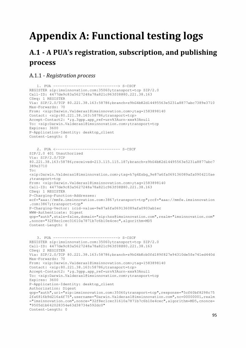
95
Appendix A: Functional testing logs
A.1 - A PUA’s registration, subscription, and publishing
process
A.1.1 - Registration process
1. PUA -----------------------------> S-CSCF REGISTER sip:imsinnovation.com:35060;transport=tcp SIP/2.0
Call-ID: [email protected]
CSeq: 1 REGISTER
Via: SIP/2.0/TCP 80.221.38.163:58786;branch=z9hG4bK2d14495563e5231a8877abc7389e3710
Max-Forwards: 70
From: <sip:[email protected]>;tag=1583898140
Contact: <sip:80.221.38.163:58786;transport=tcp>
Accept-Contact2: *;g.3gpp.app_ref=urn%3Aurn-xxx%3Anull
To: <sip:[email protected]>;transport=tcp
Expires: 3600
P-Application-Identity: desktop_client
Content-Length: 0
2. PUA <----------------------------- S-CSCF SIP/2.0 401 Unauthorized
Via: SIP/2.0/TCP
80.221.38.163:58786;received=213.115.115.187;branch=z9hG4bK2d14495563e5231a8877abc7
389e3710
To:
<sip:[email protected]>;tag=h7g4Esbg_9e87a6fa069136089afa0904210ae
;transport=tcp
From: <sip:[email protected]>;tag=1583898140
Call-ID: [email protected]
CSeq: 1 REGISTER
P-Charging-Function-Addresses:
ecf="aaa://mmfe.imsinnovation.com:3867;transport=tcp";ccf="aaa://mmfe.imsinnovation
.com:3867;transport=tcp"
P-Charging-Vector: icid-value=9e87a6fa069136089afa0903ab1ec
WWW-Authenticate: Digest
qop="auth",stale=false,domain="sip:[email protected]",realm="imsinnovation.com"
,nonce="32f8ec1cec31610a7871b7c6b10e4cec",algorithm=MD5
Content-Length: 0
3. PUA -----------------------------> S-CSCF REGISTER sip:imsinnovation.com:35060;transport=tcp SIP/2.0
Call-ID: [email protected]
CSeq: 2 REGISTER
Via: SIP/2.0/TCP 80.221.38.163:58786;branch=z9hG4bKcb0fd189f827e94310de5fe741ed440d
Max-Forwards: 70
From: <sip:[email protected]>;tag=1583898140
Contact: <sip:80.221.38.163:58786;transport=tcp>
Accept-Contact2: *;g.3gpp.app_ref=urn%3Aurn-xxx%3Anull
To: <sip:[email protected]>;transport=tcp
Expires: 3600
P-Application-Identity: desktop_client
Authorization: Digest
qop="auth",uri="sip:imsinnovation.com:35060;transport=tcp",response="5cf60bf8298c75
2fa6816b9d216a4f75",username="[email protected]",nc=00000001,realm
="imsinnovation.com",nonce="32f8ec1cec31610a7871b7c6b10e4cec",algorithm=MD5,cnonce=
"9505d1b642028354e63d38734e592dc0"
Content-Length: 0

96
4. PUA <----------------------------- S-CSCF SIP/2.0 200 OK
Via: SIP/2.0/TCP
80.221.38.163:58786;received=213.115.115.187;branch=z9hG4bKcb0fd189f827e94310de5fe7
41ed440d
To:
<sip:[email protected]>;tag=h7g4Esbg_9e87a6fa06914f089afa090be23ff
;transport=tcp
From: <sip:[email protected]>;tag=1583898140
Call-ID: [email protected]
CSeq: 2 REGISTER
Contact: <sip:80.221.38.163:58786;transport=tcp>;expires=1890
P-Associated-URI: <sip:[email protected]>
P-Charging-Function-Addresses:
ecf="aaa://mmfe.imsinnovation.com:3867;transport=tcp";ccf="aaa://mmfe.imsinnovation
.com:3867;transport=tcp"
P-Charging-Vector: icid-value=9e87a6fa06914f089afa090b9388b
Authentication-Info:
cnonce="9505d1b642028354e63d38734e592dc0",qop=auth,nextnonce="32f8ec1cec31610a7871b
7c6b10e4cec",rspauth="0e1fdff3cc7765cc0c49d069514600ab",nc=00000001
Service-Route: <sip:213.115.115.187:35060;lr;transport=tcp>
Content-Length: 0
A.1.2 - Subscription process
1. PUA -----------------------------> PGM SUBSCRIBE sip:[email protected];transport=tcp SIP/2.0
Call-ID: [email protected]
CSeq: 1 SUBSCRIBE
To: <sip:[email protected]:5060;transport=tcp>
Via: SIP/2.0/TCP 80.221.38.163:58786;branch=z9hG4bKb3cb9dae6961f7d1c2bac3f481b4b8ab
Max-Forwards: 70
From: <sip:[email protected]>;tag=1433761786
Contact: <sip:80.221.38.163:58786;transport=tcp>
Route: <sip:213.115.115.187:35060;lr;transport=tcp>
P-Application-Identity: desktop_client
Accept-Contact2: *;g.3gpp.app_ref=urn%3Aurn-xxx%3Anull
Event: presence.winfo
Expires: 3600
Content-Length: 0
2. PUA <----------------------------- PGM SIP/2.0 200 OK
Via: SIP/2.0/TCP
80.221.38.163:58786;received=213.115.115.187;branch=z9hG4bKb3cb9dae6961f7d1c2bac3f4
81b4b8ab
To:
<sip:[email protected]:5060;transport=tcp>;tag=h7g4Esbg_flm2qfum-
xyq
From: <sip:[email protected]>;tag=1433761786
Call-ID: [email protected]
CSeq: 1 SUBSCRIBE
Contact: <sip:[email protected]:35060;transport=tcp>
Record-Route: <sip:213.115.115.187:35060;lr;transport=tcp>
Expires: 3600
P-Charging-Vector: icid-value=d137184b069148089afa0a4444bd6
Server: PGM4.1_PS
Content-Length: 0
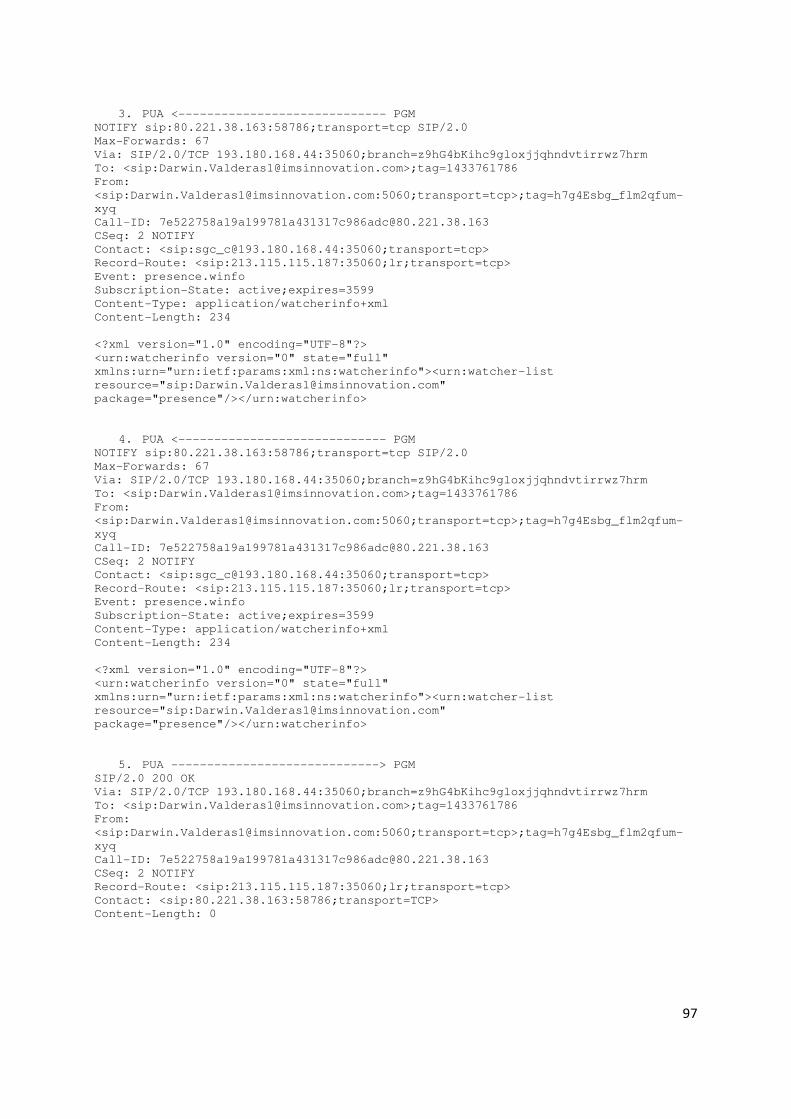
97
3. PUA <----------------------------- PGM NOTIFY sip:80.221.38.163:58786;transport=tcp SIP/2.0
Max-Forwards: 67
Via: SIP/2.0/TCP 193.180.168.44:35060;branch=z9hG4bKihc9gloxjjqhndvtirrwz7hrm
To: <sip:[email protected]>;tag=1433761786
From:
<sip:[email protected]:5060;transport=tcp>;tag=h7g4Esbg_flm2qfum-
xyq
Call-ID: [email protected]
CSeq: 2 NOTIFY
Contact: <sip:[email protected]:35060;transport=tcp>
Record-Route: <sip:213.115.115.187:35060;lr;transport=tcp>
Event: presence.winfo
Subscription-State: active;expires=3599
Content-Type: application/watcherinfo+xml
Content-Length: 234
<?xml version="1.0" encoding="UTF-8"?>
<urn:watcherinfo version="0" state="full"
xmlns:urn="urn:ietf:params:xml:ns:watcherinfo"><urn:watcher-list
resource="sip:[email protected]"
package="presence"/></urn:watcherinfo>
4. PUA <----------------------------- PGM NOTIFY sip:80.221.38.163:58786;transport=tcp SIP/2.0
Max-Forwards: 67
Via: SIP/2.0/TCP 193.180.168.44:35060;branch=z9hG4bKihc9gloxjjqhndvtirrwz7hrm
To: <sip:[email protected]>;tag=1433761786
From:
<sip:[email protected]:5060;transport=tcp>;tag=h7g4Esbg_flm2qfum-
xyq
Call-ID: [email protected]
CSeq: 2 NOTIFY
Contact: <sip:[email protected]:35060;transport=tcp>
Record-Route: <sip:213.115.115.187:35060;lr;transport=tcp>
Event: presence.winfo
Subscription-State: active;expires=3599
Content-Type: application/watcherinfo+xml
Content-Length: 234
<?xml version="1.0" encoding="UTF-8"?>
<urn:watcherinfo version="0" state="full"
xmlns:urn="urn:ietf:params:xml:ns:watcherinfo"><urn:watcher-list
resource="sip:[email protected]"
package="presence"/></urn:watcherinfo>
5. PUA -----------------------------> PGM SIP/2.0 200 OK
Via: SIP/2.0/TCP 193.180.168.44:35060;branch=z9hG4bKihc9gloxjjqhndvtirrwz7hrm
To: <sip:[email protected]>;tag=1433761786
From:
<sip:[email protected]:5060;transport=tcp>;tag=h7g4Esbg_flm2qfum-
xyq
Call-ID: [email protected]
CSeq: 2 NOTIFY
Record-Route: <sip:213.115.115.187:35060;lr;transport=tcp>
Contact: <sip:80.221.38.163:58786;transport=TCP>
Content-Length: 0

98
6. PUA -----------------------------> PGM SIP/2.0 200 OK
Via: SIP/2.0/TCP 193.180.168.44:35060;branch=z9hG4bKihc9gloxjjqhndvtirrwz7hrm
To: <sip:[email protected]>;tag=1433761786
From:
<sip:[email protected]:5060;transport=tcp>;tag=h7g4Esbg_flm2qfum-
xyq
Call-ID: [email protected]
CSeq: 2 NOTIFY
Record-Route: <sip:213.115.115.187:35060;lr;transport=tcp>
Contact: <sip:80.221.38.163:58786;transport=TCP>
Content-Length: 0
A.1.3 - Publishing process
1. PUA -----------------------------> PGM PUBLISH sip:[email protected] SIP/2.0
Call-ID: [email protected]
CSeq: 1 PUBLISH
To: <sip:[email protected]:5060;transport=tcp>
Via: SIP/2.0/TCP 80.221.38.163:58786;branch=z9hG4bKa58673877b5f92ac893fa44dac2ebd0e
Max-Forwards: 70
From: <sip:[email protected]>;tag=1573040888
Contact: <sip:80.221.38.163:58786;transport=tcp>
Route: <sip:213.115.115.187:35060;lr;transport=tcp>
P-Application-Identity: desktop_client
Accept-Contact2: *;g.3gpp.app_ref=urn%3Aurn-xxx%3Anull
Event: presence
Expires: 3600
Content-Type: application/pidf+xml
Content-Length: 903
<?xml version="1.0" encoding="UTF-8"?>
<presence xmlns:rpid="urn:ietf:params:xml:ns:pidf:rpid"
xmlns:pdm="urn:ietf:params:xml:ns:pidf:data-model"
xmlns:op="urn:oma:xml:prs:pidf:oma-pres" xmlns="urn:ietf:params:xml:ns:pidf"
entity="sip:[email protected]">
<tuple id="INQYul39">
<status>
<basic>open</basic></status>
<op:service-description>
<op:service-id>desktop_client</op:service-id>
<op:version>1.0</op:version></op:service-description>
<timestamp>2008-09-27T01:33:31.218Z</timestamp></tuple>
<pdm:person id="p1">
<pdm:note>67;67;67;00:00:00</pdm:note>
<pdm:timestamp>2008-09-27T01:33:31.218Z</pdm:timestamp>
</pdm:person>
</presence>

99
2. PGM <----------------------------- PGM SIP/2.0 200 OK
Via: SIP/2.0/TCP
80.221.38.163:58786;received=213.115.115.187;branch=z9hG4bKa58673877b5f92ac893fa44d
ac2ebd0e
To:
<sip:[email protected]:5060;transport=tcp>;tag=h7g4Esbg_flm2qiem-
xyr
From: <sip:[email protected]>;tag=1573040888
Call-ID: [email protected]
CSeq: 1 PUBLISH
Expires: 3600
P-Charging-Vector: icid-value=5d465baf0b2de1089afa2474f3c1a
SIP-ETag: 3
Server: PGM4.1_PS
Content-Length: 0
A.2 - A watcher subscribing to a presentity’s presence
information
1. Watcher -------------------------> PGM SUBSCRIBE sip:[email protected];list=MiPropiaLista_darwin SIP/2.0
P-Asserted-Identity: sip:[email protected]
From: <sip:[email protected]>;tag=fllxchxn-3
To: <sip:[email protected];list=MiPropiaLista_darwin>
Via: SIP/2.0/UDP
213.115.115.188:5060;branch=z9hG4bKdaac4351a7fbf6ca4a3dbead0a01ee8b53e0
Accept: application/pidf+xml, application/rlmi+xml, multipart/related,
application/cpim-pidf+xml
Content-Length: 0
Max-Forwards: 69
Expires: 3600
Cseq: 1 SUBSCRIBE
Contact: <sip:213.115.115.188:5060;fid=server_1>
Route: <sip:172.23.214.27:5063;lr>
Supported: eventlist
Event: presence
Call-Id: 213.115.115.188_3_2478652265596970642
2. Watcher <----------------------------- PGM SIP/2.0 200 OK
To:
<sip:[email protected];list=MiPropiaLista_darwin>;tag=fllxbafp-9dq
From: <sip:[email protected]>;tag=fllxchxn-3
Call-ID: 213.115.115.188_3_2478652265596970642
CSeq: 1 SUBSCRIBE
Content-Length: 0
Via: SIP/2.0/UDP
213.115.115.188:5060;branch=z9hG4bKdaac4351a7fbf6ca4a3dbead0a01ee8b53e0
Record-Route:
<sip:3Zqkv7%0BaGqjGaaaacqsip%3ADarwin.Valderas2%[email protected]
tion.com:5062;maddr=172.23.214.27;lr>
Record-Route: <sip:3Zqkv7%0BaHasaaaaad4sip%3ADarwin.Valderas2%40imsinnovation.com-
uac-
[email protected]:5063;maddr=172.23.214.27;lr>
Contact: <sip:172.23.214.171:22021;transport=tcp>
Require: eventlist
Expires: 3600
Server: PGM4.1_RLS
P-Charging-Vector: icid-value=be43537904c3a7089af1509e3d49c;orig-ioi=1;term-ioi=1

100
3. Watcher <----------------------------- PGM NOTIFY sip:213.115.115.188:5060;fid=server_1 SIP/2.0
To: <sip:[email protected]>;tag=fllxchxn-3
From:
<sip:[email protected];list=MiPropiaLista_darwin>;tag=fllxbafp-9dq
Call-ID: 213.115.115.188_3_2478652265596970642
CSeq: 2 NOTIFY
Max-Forwards: 67
Content-Length: 912
Via: SIP/2.0/TCP
172.23.214.27:5063;branch=z9hG4bKf065ad5136fe26822b4d5bca79a6eaa9jaaaaaaiaaaaaabukx
kya3Zqkv7v4injxsnabwnsa
Via: SIP/2.0/TCP
172.23.214.27:5060;branch=z9hG4bKe4fd8d5dcc14d6c8fa8390b6ce09e024jaaaaaaiaaaaaapxui
cla3Zqkv7f4injxtr0qdn4a
Via: SIP/2.0/TCP 172.23.214.171:22021;branch=z9hG4bK1213218k3baaaa
Record-Route:
<sip:3Zqkv7%0BaGqjOaaaaeOsip%3ADarwin.Valderas2%[email protected]
tion.com:5062;maddr=172.23.214.27;lr>
Contact: <sip:172.23.214.171:22021;transport=tcp>
Content-Type:
multipart/related;type="application/rlmi+xml";start="<sip:Darwin.Valderas2@imsinnov
ation.com;list=MiPropiaLista_darwin>"; boundary="----
=_Part_18818_32210634.1222500634629"
Require: eventlist
Subscription-State: active;expires=3599
Event: presence
------=_Part_18818_32210634.1222500634629
Content-Type: application/rlmi+xml;charset="UTF-8"
Content-Transfer-Encoding: binary
Content-ID: <sip:[email protected];list=MiPropiaLista_darwin>
<?xml version="1.0" encoding="UTF-8"?>
<list uri="sip:[email protected];list=MiPropiaLista_darwin"
version="0" fullState="true" xmlns="urn:ietf:params:xml:ns:rlmi"><resource
uri="sip:[email protected]"><instance id="1" state="active"
cid="sip:[email protected]"/></resource></list>
------=_Part_18818_32210634.1222500634629
Content-Type: application/pidf+xml;charset="UTF-8"
Content-Transfer-Encoding: binary
Content-ID: <sip:[email protected]>
<?xml version="1.0" encoding="UTF-8"?><presence xmlns="urn:ietf:params:xml:ns:pidf"
entity="sip:[email protected]"/>
------=_Part_18818_32210634.1222500634629—
4. Watcher -------------------------> PGM SIP/2.0 200 OK
Record-Route:
<sip:3Zqkv7%0BaGqjOaaaaeOsip%3ADarwin.Valderas2%[email protected]
tion.com:5062;maddr=172.23.214.27;lr>
Content-Length: 0
From:
<sip:[email protected];list=MiPropiaLista_darwin>;tag=fllxbafp-9dq
Cseq: 2 NOTIFY
Contact: <sip:213.115.115.188:5060;fid=server_1>
To: <sip:[email protected]>;tag=fllxchxn-3
Server: Glassfish_SIP_1.0.0
Via: SIP/2.0/TCP
172.23.214.27:5063;branch=z9hG4bKf065ad5136fe26822b4d5bca79a6eaa9jaaaaaaiaaaaaabukx
kya3Zqkv7v4injxsnabwnsa
Via: SIP/2.0/TCP
172.23.214.27:5060;branch=z9hG4bKe4fd8d5dcc14d6c8fa8390b6ce09e024jaaaaaaiaaaaaapxui
cla3Zqkv7f4injxtr0qdn4a
Via: SIP/2.0/TCP 172.23.214.171:22021;branch=z9hG4bK1213218k3baaaa

101
Call-Id: 213.115.115.188_3_2478652265596970642
5. Watcher <----------------------------- PGM NOTIFY sip:213.115.115.188:5060;fid=server_1 SIP/2.0
To: <sip:[email protected]>;tag=fllxchxn-3
From:
<sip:[email protected];list=MiPropiaLista_darwin>;tag=fllxbafp-9dq
Call-ID: 213.115.115.188_3_2478652265596970642
CSeq: 3 NOTIFY
Max-Forwards: 67
Content-Length: 1668
Via: SIP/2.0/TCP
172.23.214.27:5063;branch=z9hG4bK0b22504430b02b033fbf0a0b1dcfa76ajaaaaaaiaaaaaa5kxf
ceq3Zqkv7v4injxsvaptkta
Via: SIP/2.0/TCP
172.23.214.27:5060;branch=z9hG4bKa0f14bbd4b4c55033dc119d66b96a15djaaaaaaiaaaaaatbm1
ccq3Zqkv7f4injxsx0tsega
Via: SIP/2.0/TCP 172.23.214.171:22021;branch=z9hG4bK1213219k3baaaa
Record-Route:
<sip:3Zqkv7%0BaGqjOaaaagOsip%3ADarwin.Valderas2%[email protected]
tion.com:5062;maddr=172.23.214.27;lr>
Contact: <sip:172.23.214.171:22021;transport=tcp>
Content-Type:
multipart/related;type="application/rlmi+xml";start="<sip:Darwin.Valderas2@imsinnov
ation.com;list=MiPropiaLista_darwin>"; boundary="----
=_Part_18819_32230965.1222501045379"
Require: eventlist
Subscription-State: active;expires=3188
Event: presence
------=_Part_18819_32230965.1222501045379
Content-Type: application/rlmi+xml;charset="UTF-8"
Content-Transfer-Encoding: binary
Content-ID: <sip:[email protected];list=MiPropiaLista_darwin>
<?xml version="1.0" encoding="UTF-8"?>
<list uri="sip:[email protected];list=MiPropiaLista_darwin"
version="1" fullState="true" xmlns="urn:ietf:params:xml:ns:rlmi"><resource
uri="sip:[email protected]"><instance id="1" state="active"
cid="sip:[email protected]"/></resource></list>
------=_Part_18819_32230965.1222501045379
Content-Type: application/pidf+xml;charset="UTF-8"
Content-Transfer-Encoding: binary
Content-ID: <sip:[email protected]>
<?xml version="1.0" encoding="UTF-8"?>
<presence entity="sip:[email protected]"
xmlns:pt="urn:ietf:params:xml:ns:location-type" xmlns="urn:ietf:params:xml:ns:pidf"
xmlns:gml="urn:opengis:specification:gml:schema-xsd:feature:v3.0"
xmlns:pdm="urn:ietf:params:xml:ns:pidf:data-model" xmlns:other="urn:other"
xmlns:gp="urn:ietf:params:xml:ns:pidf:geopriv10"
xmlns:op="urn:oma:xml:prs:pidf:oma-pres"
xmlns:rpid="urn:ietf:params:xml:ns:pidf:rpid"
xmlns:cl="urn:ietf:params:xml:ns:pidf:geopriv10:civicLoc">
<tuple id="NYGzG0dO">
<status>
<basic>open</basic></status>
<op:service-description>
<op:service-id>mobile_client</op:service-id>
<op:version>1.0</op:version></op:service-description>
<timestamp>2008-09-27T07:37:24.157Z</timestamp></tuple>
<pdm:person id="p1">
<pdm:note>0;0;0;00:00:00</pdm:note>
<pdm:timestamp>2008-09-27T07:37:24.157Z</pdm:timestamp></pdm:person></presence>
------=_Part_18819_32230965.1222501045379—

102
6. Watcher -------------------------> PGM SIP/2.0 200 OK
Record-Route:
<sip:3Zqkv7%0BaGqjOaaaagOsip%3ADarwin.Valderas2%[email protected]
tion.com:5062;maddr=172.23.214.27;lr>
Content-Length: 0
From:
<sip:[email protected];list=MiPropiaLista_darwin>;tag=fllxbafp-9dq
Cseq: 3 NOTIFY
Contact: <sip:213.115.115.188:5060;fid=server_1>
To: <sip:[email protected]>;tag=fllxchxn-3
Server: Glassfish_SIP_1.0.0
Via: SIP/2.0/TCP
172.23.214.27:5063;branch=z9hG4bK0b22504430b02b033fbf0a0b1dcfa76ajaaaaaaiaaaaaa5kxf
ceq3Zqkv7v4injxsvaptkta
Via: SIP/2.0/TCP
172.23.214.27:5060;branch=z9hG4bKa0f14bbd4b4c55033dc119d66b96a15djaaaaaaiaaaaaatbm1
ccq3Zqkv7f4injxsx0tsega
Via: SIP/2.0/TCP 172.23.214.171:22021;branch=z9hG4bK1213219k3baaaa
Call-Id: 213.115.115.188_3_2478652265596970642
A.3 - Adding a new watcher
A.3.1 – Subscription process (showing the pending state)
1. Watcher -------------------------> PGM SUBSCRIBE sip:[email protected];list=MiPropiaLista_oscar1 SIP/2.0
P-Asserted-Identity: sip:[email protected]
From: <sip:[email protected]>;tag=flmgzumc-6
To: <sip:[email protected];list=MiPropiaLista_oscar1>
Via: SIP/2.0/UDP
213.115.115.188:5060;branch=z9hG4bKdaac7d9067722c794a0d8738d09b44d85242
Accept: application/pidf+xml, application/rlmi+xml, multipart/related,
application/cpim-pidf+xml
Content-Length: 0
Max-Forwards: 69
Expires: 3600
Cseq: 1 SUBSCRIBE
Contact: <sip:213.115.115.188:5060;fid=server_1>
Route: <sip:172.23.214.27:5063;lr>
Supported: eventlist
Event: presence
Call-Id: 213.115.115.188_6_7715831493867887540
2. Watcher <------------------------- PGM SIP/2.0 200 OK
To: <sip:[email protected];list=MiPropiaLista_oscar1>;tag=flmgyn11-xzl
From: <sip:[email protected]>;tag=flmgzumc-6
Call-ID: 213.115.115.188_6_7715831493867887540
CSeq: 1 SUBSCRIBE
Content-Length: 0
Via: SIP/2.0/UDP
213.115.115.188:5060;branch=z9hG4bKdaac7d9067722c794a0d8738d09b44d85242
Record-Route:
<sip:3Zqkv7%0BaGqiqaaaacqsip%3AOscar.Novo1%[email protected].
com:5062;maddr=172.23.214.27;lr>
Record-Route: <sip:3Zqkv7%0BaHaqWaaaad4sip%3AOscar.Novo1%40imsinnovation.com-uac-
[email protected]:5063;maddr=172.23.214.27;lr>
Contact: <sip:172.23.214.171:22023;transport=tcp>
Require: eventlist
Expires: 3600
103
Server: PGM4.1_RLS
P-Charging-Vector: icid-value=4cb495100b35dd089b10ed7453e37;orig-ioi=1;term-ioi=1
3. Watcher <------------------------- PGM NOTIFY sip:213.115.115.188:5060;fid=server_1 SIP/2.0
To: <sip:[email protected]>;tag=flmgzumc-6
From: <sip:[email protected];list=MiPropiaLista_oscar1>;tag=flmgyn11-
xzl
Call-ID: 213.115.115.188_6_7715831493867887540
CSeq: 2 NOTIFY
Max-Forwards: 67
Content-Length: 535
Via: SIP/2.0/TCP
172.23.214.27:5063;branch=z9hG4bKaba850b039b28448528877626c41e832jaaaaaaiaaaaaa1ymb
e1a3Zqkv7smwskrakzxzwaa
Via: SIP/2.0/TCP
172.23.214.27:5060;branch=z9hG4bK057030d3dec92affdaa9358c25a5baf1jaaaaaaiaaaaaadgtv
rsa3Zqkv7cmwskrbyxgnfha
Via: SIP/2.0/TCP 172.23.214.171:22023;branch=z9hG4bK1583232doeaaaa
Record-Route:
<sip:3Zqkv7%0BaGqiyaaaaeOsip%3AOscar.Novo1%[email protected].
com:5062;maddr=172.23.214.27;lr>
Contact: <sip:172.23.214.171:22023;transport=tcp>
Content-Type:
multipart/related;type="application/rlmi+xml";start="<sip:Oscar.Novo1@imsinnovation
.com;list=MiPropiaLista_oscar1>"; boundary="----=_Part_21879_5214906.1222533636417"
Require: eventlist
Subscription-State: active;expires=3599
Event: presence
------=_Part_21879_5214906.1222533636417
Content-Type: application/rlmi+xml;charset="UTF-8"
Content-Transfer-Encoding: binary
Content-ID: <sip:[email protected];list=MiPropiaLista_oscar1>
<?xml version="1.0" encoding="UTF-8"?>
<list uri="sip:[email protected];list=MiPropiaLista_oscar1" version="0"
fullState="true" xmlns="urn:ietf:params:xml:ns:rlmi"><resource
uri="sip:[email protected]"><instance id="1"
state="pending"/></resource></list>
------=_Part_21879_5214906.1222533636417--
4. Watcher -------------------------> PGM SIP/2.0 200 OK
Record-Route:
<sip:3Zqkv7%0BaGqiyaaaaeOsip%3AOscar.Novo1%[email protected].
com:5062;maddr=172.23.214.27;lr>
Content-Length: 0
From: <sip:[email protected];list=MiPropiaLista_oscar1>;tag=flmgyn11-
xzl
Cseq: 2 NOTIFY
Contact: <sip:213.115.115.188:5060;fid=server_1>
To: <sip:[email protected]>;tag=flmgzumc-6
Server: Glassfish_SIP_1.0.0
Via: SIP/2.0/TCP
172.23.214.27:5063;branch=z9hG4bKaba850b039b28448528877626c41e832jaaaaaaiaaaaaa1ymb
e1a3Zqkv7smwskrakzxzwaa
Via: SIP/2.0/TCP
172.23.214.27:5060;branch=z9hG4bK057030d3dec92affdaa9358c25a5baf1jaaaaaaiaaaaaadgtv
rsa3Zqkv7cmwskrbyxgnfha
Via: SIP/2.0/TCP 172.23.214.171:22023;branch=z9hG4bK1583232doeaaaa
Call-Id: 213.115.115.188_6_7715831493867887540

104
A.3.2 – Watcher list notification - watcher allowed to view presence
1. PUA <------------------------- PGM NOTIFY sip:80.221.38.163:54346;transport=tcp SIP/2.0
Max-Forwards: 67
Via: SIP/2.0/TCP 193.180.168.44:35060;branch=z9hG4bKuxn4758ru4nc5qy7qgqfih8nk
To: <sip:[email protected]>;tag=1234107759
From:
<sip:[email protected]:5060;transport=tcp>;tag=h7g4Esbg_flmgwtdd-
xzi
Call-ID: [email protected]
CSeq: 3 NOTIFY
Contact: <sip:[email protected]:35060;transport=tcp>
Record-Route: <sip:213.115.115.187:35060;lr;transport=tcp>
Event: presence.winfo
Subscription-State: active;expires=3514
Content-Type: application/watcherinfo+xml
Content-Length: 391
<?xml version="1.0" encoding="UTF-8"?>
<urn:watcherinfo version="1" state="partial"
xmlns:urn="urn:ietf:params:xml:ns:watcherinfo"><urn:watcher-list
resource="sip:[email protected]" package="presence"><urn:watcher
display-name="" status="pending" event="subscribe" expiration="3599"
id="0">sip:[email protected]</urn:watcher></urn:watcher-
list></urn:watcherinfo>
2. PUA -------------------------> PGM SIP/2.0 200 OK
Via: SIP/2.0/TCP 193.180.168.44:35060;branch=z9hG4bKuxn4758ru4nc5qy7qgqfih8nk
To: <sip:[email protected]>;tag=1234107759
From:
<sip:[email protected]:5060;transport=tcp>;tag=h7g4Esbg_flmgwtdd-
xzi
Call-ID: [email protected]
CSeq: 3 NOTIFY
Record-Route: <sip:213.115.115.187:35060;lr;transport=tcp>
Contact: <sip:80.221.38.163:54346;transport=TCP>
Content-Length: 0
3. Watcher <------------------------- PGM NOTIFY sip:213.115.115.188:5060;fid=server_1 SIP/2.0
To: <sip:[email protected]>;tag=flmgzumc-6
From: <sip:[email protected];list=MiPropiaLista_oscar1>;tag=flmgyn11-
xzl
Call-ID: 213.115.115.188_6_7715831493867887540
CSeq: 3 NOTIFY
Max-Forwards: 67
Content-Length: 1673
Via: SIP/2.0/TCP
172.23.214.27:5063;branch=z9hG4bK2f7314cade30d75f100e122e705e9708jaaaaaaiaaaaaat52p
ecq3Zqkv7smwskraobxxtha
Via: SIP/2.0/TCP
172.23.214.27:5060;branch=z9hG4bK8c53f1741d3ae0efb74fd3c647684c38jaaaaaaiaaaaaaewei
qka3Zqkv7cmwskrazrgouoa
Via: SIP/2.0/TCP 172.23.214.171:22023;branch=z9hG4bK1583235doeaaaa
Record-Route:
<sip:3Zqkv7%0BaGqiyaaaagOsip%3AOscar.Novo1%[email protected].
com:5062;maddr=172.23.214.27;lr>
Contact: <sip:172.23.214.171:22023;transport=tcp>
Content-Type:
multipart/related;type="application/rlmi+xml";start="<sip:Oscar.Novo1@imsinnovation
.com;list=MiPropiaLista_oscar1>"; boundary="----
=_Part_21880_10456047.1222533636799"

105
Require: eventlist
Subscription-State: active;expires=3599
Event: presence
------=_Part_21880_10456047.1222533636799
Content-Type: application/rlmi+xml;charset="UTF-8"
Content-Transfer-Encoding: binary
Content-ID: <sip:[email protected];list=MiPropiaLista_oscar1>
<?xml version="1.0" encoding="UTF-8"?>
<list uri="sip:[email protected];list=MiPropiaLista_oscar1" version="1"
fullState="true" xmlns="urn:ietf:params:xml:ns:rlmi"><resource
uri="sip:[email protected]"><instance id="1" state="active"
cid="sip:[email protected]"/></resource></list>
------=_Part_21880_10456047.1222533636799
Content-Type: application/pidf+xml;charset="UTF-8"
Content-Transfer-Encoding: binary
Content-ID: <sip:[email protected]>
<?xml version="1.0" encoding="UTF-8"?>
<presence entity="sip:[email protected]"
xmlns:pdm="urn:ietf:params:xml:ns:pidf:data-model"
xmlns:op="urn:oma:xml:prs:pidf:oma-pres" xmlns="urn:ietf:params:xml:ns:pidf">
<tuple id="iLJIQyKG">
<status>
<basic>open</basic></status>
<op:service-description>
<op:service-id>pichula</op:service-id>
<op:version>1.0</op:version></op:service-description>
<timestamp>2008-09-27T16:39:14.404Z</timestamp></tuple>
<pdm:person id="p1">
<pdm:note>80;57;86;00:10:09</pdm:note>
<pdm:timestamp>2008-09-27T16:39:14.404Z</pdm:timestamp></pdm:person></presence>
------=_Part_21880_10456047.1222533636799--
4. Watcher -------------------------> PGM SIP/2.0 200 OK
Record-Route:
<sip:3Zqkv7%0BaGqiyaaaagOsip%3AOscar.Novo1%[email protected].
com:5062;maddr=172.23.214.27;lr>
Content-Length: 0
From: <sip:[email protected];list=MiPropiaLista_oscar1>;tag=flmgyn11-
xzl
Cseq: 3 NOTIFY
Contact: <sip:213.115.115.188:5060;fid=server_1>
To: <sip:[email protected]>;tag=flmgzumc-6
Server: Glassfish_SIP_1.0.0
Via: SIP/2.0/TCP
172.23.214.27:5063;branch=z9hG4bK2f7314cade30d75f100e122e705e9708jaaaaaaiaaaaaat52p
ecq3Zqkv7smwskraobxxtha
Via: SIP/2.0/TCP
172.23.214.27:5060;branch=z9hG4bK8c53f1741d3ae0efb74fd3c647684c38jaaaaaaiaaaaaaewei
qka3Zqkv7cmwskrazrgouoa
Via: SIP/2.0/TCP 172.23.214.171:22023;branch=z9hG4bK1583235doeaaaa
Call-Id: 213.115.115.188_6_7715831493867887540
106
A.4 - Two watchers subscribing to the same HRM
user’s presence information
A.4.1 – Watchers subscription process
1. Watcher1 -------------------------> PGM SUBSCRIBE sip:[email protected];list=MiPropiaLista_darwin SIP/2.0
P-Asserted-Identity: sip:[email protected]
From: <sip:[email protected]>;tag=fllyndae-4
To: <sip:[email protected];list=MiPropiaLista_darwin>
Via: SIP/2.0/UDP
213.115.115.188:5060;branch=z9hG4bKdaac73df4083bf16499fb23af89e7e32934e
Accept: application/pidf+xml, application/rlmi+xml, multipart/related,
application/cpim-pidf+xml
Content-Length: 0
Max-Forwards: 69
Expires: 3600
Cseq: 1 SUBSCRIBE
Contact: <sip:213.115.115.188:5060;fid=server_1>
Route: <sip:172.23.214.27:5063;lr>
Supported: eventlist
Event: presence
Call-Id: 213.115.115.188_4_4938965627018318151
2. Watcher1 <------------------------- PGM SIP/2.0 200 OK
To:
<sip:[email protected];list=MiPropiaLista_darwin>;tag=fllym5sh-9dt
From: <sip:[email protected]>;tag=fllyndae-4
Call-ID: 213.115.115.188_4_4938965627018318151
CSeq: 1 SUBSCRIBE
Content-Length: 0
Via: SIP/2.0/UDP
213.115.115.188:5060;branch=z9hG4bKdaac73df4083bf16499fb23af89e7e32934e
Record-Route:
<sip:3Zqkv7%0BaGqjGaaaacqsip%3ADarwin.Valderas2%[email protected]
tion.com:5062;maddr=172.23.214.27;lr>
Record-Route: <sip:3Zqkv7%0BaHasaaaaad4sip%3ADarwin.Valderas2%40imsinnovation.com-
uac-
[email protected]:5063;maddr=172.23.214.27;lr>
Contact: <sip:172.23.214.171:22021;transport=tcp>
Require: eventlist
Expires: 3600
Server: PGM4.1_RLS
P-Charging-Vector: icid-value=a69d47c104c462089af36670fd425;orig-ioi=1;term-ioi=1
3. Watcher1 <------------------------- PGM NOTIFY sip:213.115.115.188:5060;fid=server_1 SIP/2.0
To: <sip:[email protected]>;tag=fllyndae-4
From:
<sip:[email protected];list=MiPropiaLista_darwin>;tag=fllym5sh-9dt
Call-ID: 213.115.115.188_4_4938965627018318151
CSeq: 2 NOTIFY
Max-Forwards: 67
Content-Length: 912
Via: SIP/2.0/TCP
172.23.214.27:5063;branch=z9hG4bK5bd3044f3cbe5101ecaa03142a40a35ajaaaaaaiaaaaaapkmq
lhq3Zqkv7vgtvd2dv1wjkla
107
Via: SIP/2.0/TCP
172.23.214.27:5060;branch=z9hG4bK81c4258b2265add7dd15cf7add9bb7dcjaaaaaaiaaaaaaax1y
jeq3Zqkv7fgtvd2cmeuzrca
Via: SIP/2.0/TCP 172.23.214.171:22021;branch=z9hG4bK121321km3baaaa
Record-Route:
<sip:3Zqkv7%0BaGqjOaaaagOsip%3ADarwin.Valderas2%[email protected]
tion.com:5062;maddr=172.23.214.27;lr>
Contact: <sip:172.23.214.171:22021;transport=tcp>
Content-Type:
multipart/related;type="application/rlmi+xml";start="<sip:Darwin.Valderas2@imsinnov
ation.com;list=MiPropiaLista_darwin>"; boundary="----
=_Part_18848_22625167.1222502935826"
Require: eventlist
Subscription-State: active;expires=3599
Event: presence
------=_Part_18848_22625167.1222502935826
Content-Type: application/rlmi+xml;charset="UTF-8"
Content-Transfer-Encoding: binary
Content-ID: <sip:[email protected];list=MiPropiaLista_darwin>
<?xml version="1.0" encoding="UTF-8"?>
<list uri="sip:[email protected];list=MiPropiaLista_darwin"
version="1" fullState="true" xmlns="urn:ietf:params:xml:ns:rlmi"><resource
uri="sip:[email protected]"><instance id="1" state="active"
cid="sip:[email protected]"/></resource></list>
------=_Part_18848_22625167.1222502935826
Content-Type: application/pidf+xml;charset="UTF-8"
Content-Transfer-Encoding: binary
Content-ID: <sip:[email protected]>
<?xml version="1.0" encoding="UTF-8"?><presence xmlns="urn:ietf:params:xml:ns:pidf"
entity="sip:[email protected]"/>
------=_Part_18848_22625167.1222502935826—
4. Watcher1 -------------------------> PGM SIP/2.0 200 OK
Record-Route:
<sip:3Zqkv7%0BaGqjOaaaagOsip%3ADarwin.Valderas2%[email protected]
tion.com:5062;maddr=172.23.214.27;lr>
Content-Length: 0
From:
<sip:[email protected];list=MiPropiaLista_darwin>;tag=fllym5sh-9dt
Cseq: 2 NOTIFY
Contact: <sip:213.115.115.188:5060;fid=server_1>
To: <sip:[email protected]>;tag=fllyndae-4
Server: Glassfish_SIP_1.0.0
Via: SIP/2.0/TCP
172.23.214.27:5063;branch=z9hG4bK5bd3044f3cbe5101ecaa03142a40a35ajaaaaaaiaaaaaapkmq
lhq3Zqkv7vgtvd2dv1wjkla
Via: SIP/2.0/TCP
172.23.214.27:5060;branch=z9hG4bK81c4258b2265add7dd15cf7add9bb7dcjaaaaaaiaaaaaaax1y
jeq3Zqkv7fgtvd2cmeuzrca
Via: SIP/2.0/TCP 172.23.214.171:22021;branch=z9hG4bK121321km3baaaa
Call-Id: 213.115.115.188_4_4938965627018318151
5. Watcher2 -------------------------> PGM SUBSCRIBE sip:[email protected];list=MiPropiaLista_oscar SIP/2.0
P-Asserted-Identity: sip:[email protected]
From: <sip:[email protected]>;tag=fllyoyam-5
To: <sip:[email protected];list=MiPropiaLista_oscar>
Via: SIP/2.0/UDP
213.115.115.188:5060;branch=z9hG4bKdaac8be4761ebe134f769335705b8e4cdf4f
Accept: application/pidf+xml, application/rlmi+xml, multipart/related,
application/cpim-pidf+xml
108
Content-Length: 0
Max-Forwards: 69
Expires: 3600
Cseq: 1 SUBSCRIBE
Contact: <sip:213.115.115.188:5060;fid=server_1>
Route: <sip:172.23.214.27:5063;lr>
Supported: eventlist
Event: presence
Call-Id: 213.115.115.188_5_7687429797697315274
6. Watcher2 <------------------------- PGM SIP/2.0 200 OK
To: <sip:[email protected];list=MiPropiaLista_oscar>;tag=fllynqs0-xv6
From: <sip:[email protected]>;tag=fllyoyam-5
Call-ID: 213.115.115.188_5_7687429797697315274
CSeq: 1 SUBSCRIBE
Content-Length: 0
Via: SIP/2.0/UDP
213.115.115.188:5060;branch=z9hG4bKdaac8be4761ebe134f769335705b8e4cdf4f
Record-Route:
<sip:3Zqkv7%0BaGqiqaaaacqsip%3AOscar.Novo2%[email protected].
com:5062;maddr=172.23.214.27;lr>
Record-Route: <sip:3Zqkv7%0BaHaqWaaaad4sip%3AOscar.Novo2%40imsinnovation.com-uac-
[email protected]:5063;maddr=172.23.214.27;lr>
Contact: <sip:172.23.214.171:22023;transport=tcp>
Require: eventlist
Expires: 3600
Server: PGM4.1_RLS
P-Charging-Vector: icid-value=5541de44068e15089af3837d2a69e;orig-ioi=1;term-ioi=1
7. Watcher2 <------------------------- PGM NOTIFY sip:213.115.115.188:5060;fid=server_1 SIP/2.0
To: <sip:[email protected]>;tag=fllyoyam-5
From: <sip:[email protected];list=MiPropiaLista_oscar>;tag=fllynqs0-xv6
Call-ID: 213.115.115.188_5_7687429797697315274
CSeq: 2 NOTIFY
Max-Forwards: 67
Content-Length: 900
Via: SIP/2.0/TCP
172.23.214.27:5063;branch=z9hG4bKb59c195e4966e5d9cce3f7c12a0c9b76jaaaaaaiaaaaaabjbx
eaa3Zqkv7svihpei1oyezea
Via: SIP/2.0/TCP
172.23.214.27:5060;branch=z9hG4bKb52c3253e0486c890ace096e307b3885jaaaaaaiaaaaaa4aq0
4ma3Zqkv7cvihpei0mxuqqa
Via: SIP/2.0/TCP 172.23.214.171:22023;branch=z9hG4bK158323knneaaaa
Record-Route:
<sip:3Zqkv7%0BaGqiyaaaagOsip%3AOscar.Novo2%[email protected].
com:5062;maddr=172.23.214.27;lr>
Contact: <sip:172.23.214.171:22023;transport=tcp>
Content-Type:
multipart/related;type="application/rlmi+xml";start="<sip:Oscar.Novo2@imsinnovation
.com;list=MiPropiaLista_oscar>"; boundary="----=_Part_21761_17314934.1222502935837"
Require: eventlist
Subscription-State: active;expires=3599
Event: presence
------=_Part_21761_17314934.1222502935837
Content-Type: application/rlmi+xml;charset="UTF-8"
Content-Transfer-Encoding: binary
Content-ID: <sip:[email protected];list=MiPropiaLista_oscar>
<?xml version="1.0" encoding="UTF-8"?>
<list uri="sip:[email protected];list=MiPropiaLista_oscar" version="1"
fullState="true" xmlns="urn:ietf:params:xml:ns:rlmi"><resource

109
uri="sip:[email protected]"><instance id="1" state="active"
cid="sip:[email protected]"/></resource></list>
------=_Part_21761_17314934.1222502935837
Content-Type: application/pidf+xml;charset="UTF-8"
Content-Transfer-Encoding: binary
Content-ID: <sip:[email protected]>
<?xml version="1.0" encoding="UTF-8"?><presence xmlns="urn:ietf:params:xml:ns:pidf"
entity="sip:[email protected]"/>
------=_Part_21761_17314934.1222502935837--
8. Watcher2 -------------------------> PGM SIP/2.0 200 OK
Record-Route:
<sip:3Zqkv7%0BaGqiyaaaagOsip%3AOscar.Novo2%[email protected].
com:5062;maddr=172.23.214.27;lr>
Content-Length: 0
From: <sip:[email protected];list=MiPropiaLista_oscar>;tag=fllynqs0-xv6
Cseq: 2 NOTIFY
Contact: <sip:213.115.115.188:5060;fid=server_1>
To: <sip:[email protected]>;tag=fllyoyam-5
Server: Glassfish_SIP_1.0.0
Via: SIP/2.0/TCP
172.23.214.27:5063;branch=z9hG4bKb59c195e4966e5d9cce3f7c12a0c9b76jaaaaaaiaaaaaabjbx
eaa3Zqkv7svihpei1oyezea
Via: SIP/2.0/TCP
172.23.214.27:5060;branch=z9hG4bKb52c3253e0486c890ace096e307b3885jaaaaaaiaaaaaa4aq0
4ma3Zqkv7cvihpei0mxuqqa
Via: SIP/2.0/TCP 172.23.214.171:22023;branch=z9hG4bK158323knneaaaa
Call-Id: 213.115.115.188_5_7687429797697315274
A.4.2 – A PUA publishing and watchers receiving notifications
1. PUA -------------------------> PGM
PUBLISH sip:[email protected]:35060 SIP/2.0
Call-ID: [email protected]
CSeq: 1 PUBLISH
From: <sip:[email protected]:35060>;tag=5983
To: <sip:[email protected]:35060>
Via: SIP/2.0/TCP 80.221.38.163:3245;branch=z9hG4bKca99b352946d859b281a9e6b8fb5919d
Max-Forwards: 69
Allow: INVITE,ACK,CANCEL,OPTIONS,BYE,REFER,NOTIFY,MESSAGE,SUBSCRIBE,INFO
Event: presence
Contact: <sip:[email protected]:3245>
Expires: 3600
Content-Type: application/pidf+xml
Content-Length: 643
<?xml version="1.0" encoding="utf-8"?>
<presence xmlns="urn:ietf:params:xml:ns:pidf" xmlns:op="urn:oma:xml:prs:pidf:oma-
pres" xmlns:pdm="urn:ietf:params:xml:ns:pidf:data-model"
entity="sip:[email protected]">
<tuple id="zA6Dkacz">
<status>
<basic>open</basic>
</status>
<op:service-description>
<op:service-id>desktop_client</op:service-id>
<op:version>1.0</op:version>
</op:service-description>
<timestamp>2008-09-27T11:11:54.468Z</timestamp>
</tuple>
<pdm:person id="p1">
<pdm:note>86;86;86;00:00:00</pdm:note>
110
<pdm:timestamp>2008-09-27T11:11:54.468Z</pdm:timestamp>
</pdm:person>
</presence>
2. PGM -------------------------> PUA SIP/2.0 200 OK
Via: SIP/2.0/TCP
80.221.38.163:3245;received=213.115.115.187;branch=z9hG4bKca99b352946d859b281a9e6b8
fb5919d
To: <sip:[email protected]:35060>;tag=h7g4Esbg_fllyrbfc-xvb
From: <sip:[email protected]:35060>;tag=5983
Call-ID: [email protected]
CSeq: 1 PUBLISH
Expires: 3600
P-Charging-Vector: icid-value=cefe160804c483089af3a0d557a3d
SIP-ETag: 1
Server: PGM4.1_PS
Content-Length: 0
3. PGM -------------------------> Watcher2 NOTIFY sip:213.115.115.188:5060;fid=server_1 SIP/2.0
To: <sip:[email protected]>;tag=fllyoyam-5
From: <sip:[email protected];list=MiPropiaLista_oscar>;tag=fllynqs0-xv6
Call-ID: 213.115.115.188_5_7687429797697315274
CSeq: 4 NOTIFY
Max-Forwards: 67
Content-Length: 1392
Via: SIP/2.0/TCP
172.23.214.27:5063;branch=z9hG4bKe9980b6c365131ba1bf4d7de02485e6djaaaaaaiaaaaaau2xv
xyq3Zqkv7svihpeiahkpepa
Via: SIP/2.0/TCP
172.23.214.27:5060;branch=z9hG4bKe79ec709375d1d297c7a3446f1e744c9jaaaaaaiaaaaaaloeg
0ea3Zqkv7cvihpej2w1gp0a
Via: SIP/2.0/TCP 172.23.214.171:22023;branch=z9hG4bK158323unneaaaa
Record-Route:
<sip:3Zqkv7%0BaGqiyaaaaiOsip%3AOscar.Novo2%[email protected].
com:5062;maddr=172.23.214.27;lr>
Contact: <sip:172.23.214.171:22023;transport=tcp>
Content-Type:
multipart/related;type="application/rlmi+xml";start="<sip:Oscar.Novo2@imsinnovation
.com;list=MiPropiaLista_oscar>"; boundary="----=_Part_21762_30367093.1222503061673"
Require: eventlist
Subscription-State: active;expires=3433
Event: presence
------=_Part_21762_30367093.1222503061673
Content-Type: application/rlmi+xml;charset="UTF-8"
Content-Transfer-Encoding: binary
Content-ID: <sip:[email protected];list=MiPropiaLista_oscar>
<?xml version="1.0" encoding="UTF-8"?>
<list uri="sip:[email protected];list=MiPropiaLista_oscar" version="2"
fullState="true" xmlns="urn:ietf:params:xml:ns:rlmi"><resource
uri="sip:[email protected]"><instance id="1" state="active"
cid="sip:[email protected]"/></resource></list>
------=_Part_21762_30367093.1222503061673
Content-Type: application/pidf+xml;charset="UTF-8"
Content-Transfer-Encoding: binary
Content-ID: <sip:[email protected]>
<?xml version="1.0" encoding="UTF-8"?>
<presence entity="sip:[email protected]"
xmlns="urn:ietf:params:xml:ns:pidf" xmlns:op="urn:oma:xml:prs:pidf:oma-pres"
xmlns:pdm="urn:ietf:params:xml:ns:pidf:data-model">
<tuple id="zA6Dkacz">
111
<status>
<basic>open</basic>
</status>
<op:service-description>
<op:service-id>desktop_client</op:service-id>
<op:version>1.0</op:version>
</op:service-description>
<timestamp>2008-09-27T08:11:00.240Z</timestamp>
</tuple>
<pdm:person id="p1">
<pdm:note>86;86;86;00:00:00</pdm:note>
<pdm:timestamp>2008-09-27T08:11:00.240Z</pdm:timestamp>
</pdm:person>
</presence>
------=_Part_21762_30367093.1222503061673--
4. Watcher2 -------------------------> PGM SIP/2.0 200 OK
Record-Route:
<sip:3Zqkv7%0BaGqiyaaaaiOsip%3AOscar.Novo2%[email protected].
com:5062;maddr=172.23.214.27;lr>
Content-Length: 0
From: <sip:[email protected];list=MiPropiaLista_oscar>;tag=fllynqs0-xv6
Cseq: 4 NOTIFY
Contact: <sip:213.115.115.188:5060;fid=server_1>
To: <sip:[email protected]>;tag=fllyoyam-5
Server: Glassfish_SIP_1.0.0
Via: SIP/2.0/TCP
172.23.214.27:5063;branch=z9hG4bKe9980b6c365131ba1bf4d7de02485e6djaaaaaaiaaaaaau2xv
xyq3Zqkv7svihpeiahkpepa
Via: SIP/2.0/TCP
172.23.214.27:5060;branch=z9hG4bKe79ec709375d1d297c7a3446f1e744c9jaaaaaaiaaaaaaloeg
0ea3Zqkv7cvihpej2w1gp0a
Via: SIP/2.0/TCP 172.23.214.171:22023;branch=z9hG4bK158323unneaaaa
Call-Id: 213.115.115.188_5_7687429797697315274
5. PGM -------------------------> Watcher1 NOTIFY sip:213.115.115.188:5060;fid=server_1 SIP/2.0
To: <sip:[email protected]>;tag=fllyndae-4
From:
<sip:[email protected];list=MiPropiaLista_darwin>;tag=fllym5sh-9dt
Call-ID: 213.115.115.188_4_4938965627018318151
CSeq: 4 NOTIFY
Max-Forwards: 67
Content-Length: 1404
Via: SIP/2.0/TCP
172.23.214.27:5063;branch=z9hG4bK3a2e55f030c5892da46ccd090b0bd141jaaaaaaiaaaaaamkni
dtq3Zqkv7vgtvd2c2j3ubna
Via: SIP/2.0/TCP
172.23.214.27:5060;branch=z9hG4bK9344085f534fe115db2c654316809a33jaaaaaaiaaaaaahvnx
5na3Zqkv7fgtvd2cwigg11a
Via: SIP/2.0/TCP 172.23.214.171:22021;branch=z9hG4bK121321lm3baaaa
Record-Route:
<sip:3Zqkv7%0BaGqjOaaaaiOsip%3ADarwin.Valderas2%[email protected]
tion.com:5062;maddr=172.23.214.27;lr>
Contact: <sip:172.23.214.171:22021;transport=tcp>
Content-Type:
multipart/related;type="application/rlmi+xml";start="<sip:Darwin.Valderas2@imsinnov
ation.com;list=MiPropiaLista_darwin>"; boundary="----
=_Part_18849_21592757.1222503061675"
Require: eventlist
Subscription-State: active;expires=3359
Event: presence
------=_Part_18849_21592757.1222503061675

112
Content-Type: application/rlmi+xml;charset="UTF-8"
Content-Transfer-Encoding: binary
Content-ID: <sip:[email protected];list=MiPropiaLista_darwin>
<?xml version="1.0" encoding="UTF-8"?>
<list uri="sip:[email protected];list=MiPropiaLista_darwin"
version="2" fullState="true" xmlns="urn:ietf:params:xml:ns:rlmi"><resource
uri="sip:[email protected]"><instance id="1" state="active"
cid="sip:[email protected]"/></resource></list>
------=_Part_18849_21592757.1222503061675
Content-Type: application/pidf+xml;charset="UTF-8"
Content-Transfer-Encoding: binary
Content-ID: <sip:[email protected]>
<?xml version="1.0" encoding="UTF-8"?>
<presence entity="sip:[email protected]"
xmlns="urn:ietf:params:xml:ns:pidf" xmlns:op="urn:oma:xml:prs:pidf:oma-pres"
xmlns:pdm="urn:ietf:params:xml:ns:pidf:data-model">
<tuple id="zA6Dkacz">
<status>
<basic>open</basic>
</status>
<op:service-description>
<op:service-id>desktop_client</op:service-id>
<op:version>1.0</op:version>
</op:service-description>
<timestamp>2008-09-27T08:11:00.240Z</timestamp>
</tuple>
<pdm:person id="p1">
<pdm:note>86;86;86;00:00:00</pdm:note>
<pdm:timestamp>2008-09-27T08:11:00.240Z</pdm:timestamp>
</pdm:person>
</presence>
------=_Part_18849_21592757.1222503061675--
6. Watcher1 -------------------------> PGM SIP/2.0 200 OK
Record-Route:
<sip:3Zqkv7%0BaGqjOaaaaiOsip%3ADarwin.Valderas2%[email protected]
tion.com:5062;maddr=172.23.214.27;lr>
Content-Length: 0
From:
<sip:[email protected];list=MiPropiaLista_darwin>;tag=fllym5sh-9dt
Cseq: 4 NOTIFY
Contact: <sip:213.115.115.188:5060;fid=server_1>
To: <sip:[email protected]>;tag=fllyndae-4
Server: Glassfish_SIP_1.0.0
Via: SIP/2.0/TCP
172.23.214.27:5063;branch=z9hG4bK3a2e55f030c5892da46ccd090b0bd141jaaaaaaiaaaaaamkni
dtq3Zqkv7vgtvd2c2j3ubna
Via: SIP/2.0/TCP
172.23.214.27:5060;branch=z9hG4bK9344085f534fe115db2c654316809a33jaaaaaaiaaaaaahvnx
5na3Zqkv7fgtvd2cwigg11a
Via: SIP/2.0/TCP 172.23.214.171:22021;branch=z9hG4bK121321lm3baaaa
Call-Id: 213.115.115.188_4_4938965627018318151

www.kth.se
COS/CCS 2008-22