integration reference manual
TRANSCRIPT

This PDF is generated from authoritative online content, andis provided for convenience only. This PDF cannot be usedfor legal purposes. For authoritative understanding of whatis and is not supported, always use the online content. Tocopy code samples, always use the online content.
SIP Server 8.1.1
Integration Reference Manual
12/29/2021

Table of ContentsSIP Server 8.1 Integration Reference 3Siemens OpenScape Voice 5
SIP Server and OpenScape Voice Integration Overview 6Configuring OpenScape Voice 10Configuring DN Objects 33Support for First-Party Call-Control Operations 41Support for Split-Node Deployments 42Handling Call Forwarding Loop 44
Cisco Unified Communications Manager 45Managing Agents over SIP 46Configuring CUCM 51Configuring DN Objects 52
Cisco Media Gateway 55SIP Server and Cisco Media Gateway Integration Overview 56Configuring Cisco Media Gateway 58Configuring DN Objects 64
F5 Networks BIG-IP LTM 66SIP Server and BIG-IP LTM Integration Overview 67Configuring SIP Server HA 72Configuring BIG-IP LTM 75Configuring TLS 99Deployment Architecture Example 103
RedSky E911 Manager 104

SIP Server 8.1 Integration ReferenceWelcome to the SIP Server 8.1 Integration Reference. This document introduces you to the concepts,terminology, and procedures related to integrating SIP Server with SIP endpoints, softswitches, andgateways. The reference information includes, but is not limited to, configuration options, limitations,and switch-specific functionality. This document is designed to be used along with the SIP ServerDeployment Guide.
SIP Endpoint Application Notes
Polycom SIP PhonesCounterPath Bria SIP PhonesYealink SIP PhonesAudioCodes/Genesys SIP PhonesGrandstream GXP SIP PhonesGrandstream GXP1625/GCC1700 SIPPhonesTenacity accessaphone ipTTY SIP Phones
SBC Application Notes
Sonus 1000/2000 SBCSonus 5000 SBCAudioCodes Mediant SBCOracle Enterprise SBCOracle Acme Packet E-SBC Version 8.3.xCUBE SBCRibbon Q21 SBC
Switch Integrations
Siemens OpenScape VoiceCisco Unified Communications ManagerAlcatel OXEBroadSoft BroadWorksRedSky E911 Manager
SIP Trunks Application Notes
AT&T IP Toll Free with AudioCodesMediant SBCAT&T IP Flexible Reach with AudioCodesMediant SBCAT&T IPTF and IPXC with Sonus SBC GSX/PSXColt SIP Trunk with AudioCodes MediantSBCTelenor SIP Trunk with AudioCodesMediant SBCWindstream SIP Trunk with AudioCodesMediant SBCCenturyLink SIP Trunk with AudioCodes
SIP Server 8.1 Integration Reference
Integration Reference Manual 3

Mediant SBCAireSpring SIP Trunk with AudioCodesMediant SBCBT Italia SIP Trunk with AudioCodesMediant SBCItalTel SIP Trunk with AudioCodes MediantSBC
Media Gateway Application Notes
AudioCodes Mediant GatewayCisco Media Gateway
Network Load Balancer Integrations
F5 Networks BIG-IP LTM
SIP Endpoint SDK
SIP Endpoint SDK
SIP Server 8.1 Integration Reference
Integration Reference Manual 4

Siemens OpenScape VoiceThis topic describes how to integrate SIP Server with the Siemens OpenScape Voice. It contains thefollowing sections:
• Overview• Configuring OpenScape Voice• Configuring DN Objects• Support for First-Party Call-Control Operations• Support for Split-Node Deployments• Handling Call Forwarding Loop
Note: The instructions in this topic assume that OpenScape Voice is fully functional and is routingcalls before Genesys products are installed. They also assume that SIP Server has already beenconfigured to function properly in stand-alone mode, and that configuration between SIP Server andUniversal Routing Server (URS) has already been completed.
Siemens OpenScape Voice
Integration Reference Manual 5

SIP Server and OpenScape VoiceIntegration OverviewThe SIP Server and OpenScape Voice integration solution that is described in this topic is not the onlymethod that will work. Although there are other methods, this is the only one that has been testedand approved by Genesys, and that is supported by Genesys Customer Support. This topic containsbest-practice guidelines that have been determined by both Genesys and Siemens Engineeringdepartments. Deviating from the solution that is described in this topic can have unexpectedconsequences.
Although this topic provides steps to log in to OpenScape Voice, login credentials are site-specific andshould be different for each installation, due to the nature of the equipment.
Note: The OpenScape Voice screen captures in this topic were taken from the HiPath Assistant3.0R0.0.0 Build 860. Depending on your onsite version, the onscreen output might differ.
Assumptions
The integration solution described in this topic makes the following assumptions about the desiredcall flow:
• Agent endpoints (SIP Phones) register directly with OpenScape Voice. Genesys SIP Server does notsignal these endpoints directly; instead, it always goes through OpenScape Voice.
• A single instance of SIP Server is configured behind OpenScape Voice.• If it is used for treatments, music on hold, MCU (Multipoint Conference Unit) recording, and supervisor
functionality, Media Server is signaled only by SIP Server. No direct SIP signaling occurs betweenOpenScape Voice and Media Server. For information about configuring SIP Server to use Media Server,see the Framework 8.1 SIP Server Deployment Guide.
In the event that these assumptions are not valid for the required deployment, you can still configureSIP Server for integration with OpenScape Voice; however, you might have to modify theconfiguration that is described in this topic.
To configure multiple instances of SIP Server to work with OpenScape Voice, create a uniqueNumbering Plan for each SIP Server and each group of agents that is associated with it and relatedswitch entities, as described in Configuring OpenScape Voice. For example, to configure two SIPServers, create two unique SIP Server Numbering Plans, two Agent Numbering Plans, and all relatedswitch entities as required for each Numbering Plan.
For GVP integration with SIP Server, the configuration must be performed on the SIP Server side, noton the OpenScape Voice side.
Siemens OpenScape Voice SIP Server and OpenScape Voice Integration Overview
Integration Reference Manual 6

Endpoint Support
When Genesys SIP Server is integrated with Siemens OpenScape Voice, the endpoints registerdirectly to the Siemens switch. Genesys validates the integration using a representative selection ofendpoints recommended by Siemens. However, this selection is not an exhaustive list of endpoints,and Genesys defers the official endpoint support statement to Siemens. Also note that the Click-to-Answer feature requires the referenced Patchset on OpenScape Voice and a device that supports it.
Deployment Architecture
A successful implementation requires that Genesys SIP Server be in the communications path forevery call in the contact center, both internal and external (see the following figure). This can bedone efficiently and effectively by using multiple Numbering Plans. Note, however, that gatewaysshould not be put into the Global Numbering Plan. Doing so can cause complications by routinggateway calls directly to the agents, bypassing SIP Server.
SIP Server - OpenScape Voice Deployment Architecture
In the General Numbering Plan (the Numbering Plan that contains the gateways), the contact centeris given a range of numbers for agents (assuming that the agents have direct lines) and RoutingPoints. Those numbers route directly to SIP Server, which then routes the calls accordingly.
SIP Server must have its own Numbering Plan, because it will make calls on behalf of the agents.These calls are sent to the E.164 Numbering Plan (to reach internal phones) or, if necessary, toavailable gateways.
The Agent Numbering Plan is simple; all calls go to SIP Server. The configuration of SIP ServerNumbering Plan will determine how the calls should be routed.
Other HA Deployment ArchitectureGenesys supports an alternative HA deployment architecture for OpenScape Voice. The OpenScapeVoice softswitch uses an internal mechanism to detect the active SIP Server. This architecture doesnot require Windows Network Load Balancing (NLB) or IP Address Takeover HA methods.
Siemens OpenScape Voice SIP Server and OpenScape Voice Integration Overview
Integration Reference Manual 7

Alternative HA Deployment Architecture
Main configuration points for this deployment in OpenScape Voice are:
• Configure a SIP Endpoint for SIP Server.• For the Endpoint Type, select SIP Trunking and type Dynamic.• Associate primary and backup SIP Server IP addresses as aliases for a SIP Endpoint. For example:
Main configuration points for this deployment on the Genesys side are:
• Configure a Trunk DN to point to the SIP Endpoint configured in the OpenScape Voice softswitch. It mustcontain these configuration options:• contact=sip:<OpenScape Voice IP address>:<SIP port>;transport=tcp—The contact URI
that SIP Server uses for communication with OpenScape Voice, where <IP address> is the IPaddress of the softswitch and <SIP port> is the SIP port number of the softswitch.
• force-register=sip:<SIP Endpoint name>@<OpenScape Voice IP address>:<SIPport>—Enable trunk registration on the OpenScape SIP Endpoint.
• oos-check— Specify how often (in seconds) SIP Server checks a device for out-of-service status.• oos-force—Specify when SIP Server places an unresponsive device into out-of-service state when
the oos-check option is enabled.
• Configure two sip-address SIP Server application-level options to specify both primary and backup SIPServer IP addresses.
Deployment Limitation
After a SIP Server switchover, first-party call control (1pcc) operations with established calls might
Siemens OpenScape Voice SIP Server and OpenScape Voice Integration Overview
Integration Reference Manual 8

cause the calls to be dropped. This limitation does not affect third-party call control (3pcc)operations.
Accessing Configuration Tools
HiPath AssistantThe HiPath Assistant is a thin, Web-based application that runs within a browser to provide a commonuser experience. It is primarily intended for use as a Service Management Center that providesadministrators of communications networks with provisioning information and control over theirsubscribers' voice services. Its purpose is to provide enterprises with a cost-effective, IP-basedsystem that works seamlessly with OpenScape Voice.
For enterprises with more than 5,000 lines, the HiPath Assistant can be installed on an externalserver as a stand-alone (off-board) installation, separated from the OpenScape Voice switch.
To access the HiPath Assistant, enter the following URL in your browser:
https://<IP Address>
Command-Line InterfaceOpenScape Voice also has an SSL (Secure Sockets Layer) command-line interface that you canaccess. SSL is the same as Telnet, except that it is encrypted to provide more security. There aremany SSL client applications available on the Web for free, in addition to commercial applications. Acommon application for SSL is PuTTY. You can download PuTTY from the following web page:
http://www.chiark.greenend.org.uk/~sgtatham/putty/download.html.
After you have your SSL application, configure it to connect to the management IP address ofOpenScape Voice.
Integration Task Summary
To integrate SIP Server with OpenScape Voice, complete the following procedures:
1. Configure OpenScape Voice.
2. Configure DN objects in the Configuration Layer.
Siemens OpenScape Voice SIP Server and OpenScape Voice Integration Overview
Integration Reference Manual 9

Configuring OpenScape VoiceThis page provides an overview of the main steps that are required to configure OpenScape Voice.Complete all steps in the order in which they are listed.
1. Check that OpenScape Voice is working2. Configure Numbering Plans3. Configure the Endpoint Profile4. Configure the Endpoint5. Configure Gateway Destinations6. Configure Prefix Access Codes7. Configure Destination Codes8. Configure Agent Destinations9. Configure Agent Access and Destination Codes
10. (Optional) Configure Click-to-Answer11. (Optional) Configure emergency call routing
1. Check Minimum Functionality in OpenScape VoiceThe procedures in this topic assume that OpenScape Voice is functional and routing callsappropriately. There should already be at least one Numbering Plan that has gateways and nonagentsubscribers in it. For more information, see Siemens OpenScape Voice-specific documentation.
2. Configuring Numbering PlansThe instructions in this topic assume that OpenScape Voice is functional and routing callsappropriately. There should already be at least one Numbering Plan with configured gateways andnonagent subscribers.
Purpose: To create the Numbering Plans that will contain the Agents and SIP Server.
Start
1. Log in to the HiPath Assistant, and navigate to the Business Group of the contact center that you wantto configure--for example, GenesysLab.
Siemens OpenScape Voice Configuring OpenScape Voice
Integration Reference Manual 10

Selecting the Business Group
2. Click Private Numbering Plans.
Selecting Private Numbering Plans
3. In the Private Numbering Plans dialog box, click Add.4. Add two new Private Numbering Plans: one for your agents and one for SIP Server itself--for example,
Agents and SIPServer, respectively.
Creating Private Numbering Plans
When you are finished, the dialog box shown in the following figure appears.
Siemens OpenScape Voice Configuring OpenScape Voice
Integration Reference Manual 11

Private Numbering Plans
End
3. Configuring a SIP Server Endpoint ProfileStart
1. Click Private Numbering Plan, and then click the SIP Server Numbering Plan—for example,SIPServer.
Selecting the Numbering Plan
2. Click Endpoint Management, and then click Endpoint Profiles.
Selecting Endpoint Profiles
3. In the Endpoint Profile: <Business Group> dialog box on the General tab, enter a name for thisconfigured Endpoint Profile in the Name text box. This will associate the endpoint that uses it with theNumbering Plan in which the Endpoint Profile was created.
Siemens OpenScape Voice Configuring OpenScape Voice
Integration Reference Manual 12

Configuring an Endpoint Profile
4. (Optional) If there are existing dialing rules and conventions that require the use of Class of Service andRouting Areas, enter that information. As a general rule, give this Endpoint Profile the same callingaccess as you would give to your agents
5. When you are finished, click Save.6. In the Endpoint Profile: <Business Group> dialog box on the Services tab, enable the Call
Transfer service, by selecting Yes from the drop-down menu.
Enabling the Call Transfer Service
End
4. Configuring a SIP Server EndpointStart
1. Click Private Numbering Plan, and then click the SIP Server Numbering Plan—for example,SIPServer.
2. Click Endpoints, and then click Add.
Siemens OpenScape Voice Configuring OpenScape Voice
Integration Reference Manual 13

Selecting Endpoints
3. In the Endpoint: <Business Group> dialog box, click the General tab, and do the following:a. In the Name text box, enter a unique name for this configured Endpoint.b. Select the Registered check box.c. Set the Profile text box to the Endpoint Profile that you created for SIP Server, by clicking the
browse (...) button.
Configuring Endpoints: General Tab
4. In the Endpoint: <Business Group> dialog box, click the SIP tab, and do the following:a. Make sure that the Type text box is set to Static.b. In the Endpoint Address text box, enter the IP address of SIP Server.c. From the Transport protocol drop-down box, select UDP or TCP, depending on SIP Server.
Siemens OpenScape Voice Configuring OpenScape Voice
Integration Reference Manual 14

Configuring Endpoints: SIP Tab
5. Click the Attributes tab, and do the following:a. Select the Transfer HandOff check box.
There is a known limitation of the Transfer HandOff feature. The full number must be used totransfer a call when this feature is activated.
b. Select the Do not Send Invite without SDP check box.c. When you are done, click Save.
Configuring Endpoints: Attributes Tab
6. Click the Aliases tab, and then click Add.7. In the Alias dialog box, do the following:
a. In the Name text box, enter the IP address that you entered in the Endpoint Address text box inStep 4.
b. Unless you have OpenScape Voice version 5 and later, set the Type text box to SIP URL. (This isdone automatically in version 5.)
c. Click OK.
Siemens OpenScape Voice Configuring OpenScape Voice
Integration Reference Manual 15

Configuring Endpoints: Aliases Tab
8. In the Endpoint dialog box, click Save.9. When the confirmation message box appears, informing you that the Endpoint was created successfully,
click Close.
End
5. Configuring SIP Server Destinations for GatewaysPurpose: To create Gateway Destinations for SIP Server to route calls. The Endpoints of suchGateway Destinations must already be configured in OpenScape Voice. SIP Server routes calls toGateways and to phones. Because calls to the phones are routed via the E.164 Numbering Plan, noDestinations have to be configured for them.
Start
1. Click Private Numbering Plan, and then click the SIP Server Numbering Plan—for example,SIPServer.
2. Click Destinations and Routes, then Destinations, and then click Add.
Selecting Destinations
3. In the Destination dialog box, on the General tab, do the following:a. In the Name text box, enter a unique name for the Destination—for example, SIPServerGWDEST. The
name must be unique within the switch configuration database.b. Make sure that all check boxes are cleared.
Siemens OpenScape Voice Configuring OpenScape Voice
Integration Reference Manual 16

c. When you are finished, click Save.
Configuring a Gateway Destination
4. In the Destination - <Business Group> dialog box, click the Destination that you just created.5. Click the Routes tab, and then click Add.6. In the Route dialog box, do the following:
a. In the ID text box, enter 1 for this particular route.b. Set the Type text box to SIP Endpoint.c. Set the SIP Endpoint text box to the Endpoint that you created in Configuring a SIP Server
Endpoint by clicking the browse (...) button, selecting the Numbering Plan that contains theEndpoint for the gateway to which you will be routing (for example, the general Numbering Plan),and then selecting the Endpoint.
d. Do not modify the digit string for calls that are being routed from SIP Server. All modifications tothe digit string should be completed before the calls arrive to SIP Server.
Siemens OpenScape Voice Configuring OpenScape Voice
Integration Reference Manual 17

Configuring a Route for a Gateway Destination
5. When you are finished, click Save.6. When the confirmation message box appears, informing you that the Route was added successfully,
click Close.7. In the Destination dialog box, click OK. You will now be able to view the Route that you just created in
the Routes dialog box.8. Repeat Steps 2-9 to create other gateway Destinations for SIP Server, as necessary.
End
6. Configuring SIP Server Prefix Access CodesPurpose: To configure Prefix Access Codes that SIP Server will dial to reach Subscribers andGateways.
Start
1. Click Private Numbering Plan, and then click the SIP Server Numbering Plan—for example,SIPServer.
2. Click Translation, click Prefix Access Codes, and then click Add.
Siemens OpenScape Voice Configuring OpenScape Voice
Integration Reference Manual 18

Selecting Prefix Access Codes
3. For calls that are to be routed to Subscribers: In the Prefix Access Code: <Business Group> dialogbox, do the following:a. In the Prefix Access Code text box, enter the digits you want to use to route calls to Subscribers.
Note: For the SIP Server Numbering Plan, minimal modifications should be required. Dialednumbers should be modified before they reach SIP Server. This convention should be followed atall sites, to simplify the solution as much as possible.
b. Set the Prefix Type text box to Off-net Access.c. Set the Nature of Address text box to Unknown.d. Set the Destination Type text box to E164 Destination.e. Click Save.
Siemens OpenScape Voice Configuring OpenScape Voice
Integration Reference Manual 19

Configuring a Prefix Access Code for Calls Routed toSubscribers
6. When the confirmation message box appears, informing you that the Prefix Access Code was createdsuccessfully, click Close.
7. If agents will be allowed to make external calls: In the Prefix Access Code dialog box, click Add again.8. In the Prefix Access Code dialog box, do the following:
a. In the Prefix Access Code text box, enter the digits that you want to use to route calls toGateways. The matched digits will be site-specific, and there should be minimal modification of thedigit string.
b. Set the Prefix Type text box to Off-net Access.c. Set the Nature of Address text box to Unknown.d. Set the Destination Type text box to None, so you will be able to route the call from a Destination
Code.e. Click OK.
Siemens OpenScape Voice Configuring OpenScape Voice
Integration Reference Manual 20

Configuring a Prefix Access Code for Calls Routed toGateways
6. When the confirmation message box appears, informing you that the Prefix Access Code was createdsuccessfully, click Close.
End
Next Steps
Continue with the following procedure, unless calls are routed only to Subscribers:
• Configuring SIP Server Destination Codes
7. Configuring SIP Server Destination CodesPurpose: To configure SIP Server Destination Codes to route calls to non-Subscriber devices.
Start
1. Click Private Numbering Plan, and then click the SIP Server Numbering Plan—for example,SIPServer.
2. Click Prefix Access Codes.3. Click the Prefix Access Code that you created for non-Subscriber devices.
Siemens OpenScape Voice Configuring OpenScape Voice
Integration Reference Manual 21

Selecting a Prefix Access Code
4. In the Prefix Access Code dialog box, click the Destination Codes tab.5. In the Destination Code dialog box, do the following:
a. Set the Destination Type text box to Destination.b. Set the Destination Name text box to the Destination that you created for SIP Server in Configuring
SIP Server Destinations for Gateways, by clicking the browse (...) button.
Configuring a Destination Code
6. Click Save.7. When the confirmation message box appears, informing you that the Destination Code was created
Siemens OpenScape Voice Configuring OpenScape Voice
Integration Reference Manual 22
successfully, click Close.
End
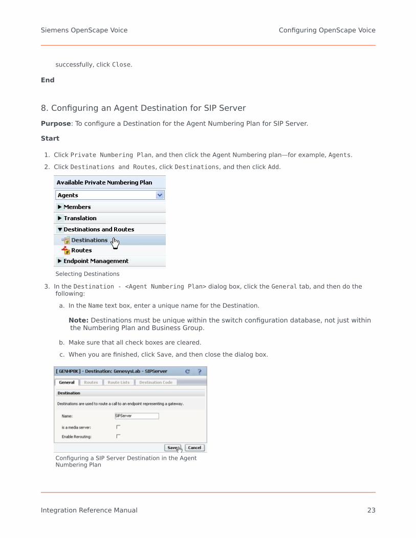
8. Configuring an Agent Destination for SIP ServerPurpose: To configure a Destination for the Agent Numbering Plan for SIP Server.
Start
1. Click Private Numbering Plan, and then click the Agent Numbering plan—for example, Agents.2. Click Destinations and Routes, click Destinations, and then click Add.
Selecting Destinations
3. In the Destination - <Agent Numbering Plan> dialog box, click the General tab, and then do thefollowing:a. In the Name text box, enter a unique name for the Destination.
Note: Destinations must be unique within the switch configuration database, not just withinthe Numbering Plan and Business Group.
b. Make sure that all check boxes are cleared.c. When you are finished, click Save, and then close the dialog box.
Configuring a SIP Server Destination in the AgentNumbering Plan
Siemens OpenScape Voice Configuring OpenScape Voice
Integration Reference Manual 23

4. Click the Destination that you just created—for example, SIPServer.5. Click the Routes tab, and then click Add.6. In the Route dialog box, do the following:
a. In the ID text box, enter 1.
Note: The ID of the first Route must always be 1.
b. Set the Type text box to SIP Endpoint.c. Set the SIP Endpoint text box to the Endpoint that you created for SIP Server in Configuring a SIP
Server Endpoint, by clicking the browse (...) button.d. When you are finished, click Save.
Note: Genesys recommends that you not modify the dialed-digit string that is passed on toSIP Server at this point.
Configuring a Route for SIP Server in the AgentNumbering Plan
5. When the confirmation message box appears, informing you that the Route was added successfully,click Close.
End
Siemens OpenScape Voice Configuring OpenScape Voice
Integration Reference Manual 24

9. Configuring Agent Prefix Access Codes and Destination CodesIn this section, you configure dialing patterns for the Agents. Every number that the agent dials mustbe configured. If an agent dials a four-digit extension, the Prefix Access Code should be configured toconvert the dialed-digit string to the full E.164 code that OpenScape Voice expects. If the agent dialsa number that must to be routed to an external gateway, make sure that the dialed-digit string iscorrect for that gateway before it reaches SIP Server.
As mentioned earlier, all calls must go to SIP Server first; otherwise, the calls will not be visible to SIPServer. In the Private Numbering Plan for agents, every Prefix Access Code must route the call to aDestination Code that points the call to SIP Server. It is best to copy the nonagent Prefix AccessCodes from the General Numbering Plan; however, make sure that the destination is always SIPServer.
Start
1. Click Private Numbering Plan, and then click the Agent Numbering Plan—for example, Agents.2. Click Translation, click Prefix Access Codes, and then click Add.3. In the Prefix Access Code dialog box, do the following:
a. In the Prefix Access Code text box, enter the digits you that want to use for routing, and anymodifications that OpenScape Voice will need to make in order to route the call properly.
b. Set the Prefix Type text box to Off-net Access.c. Set the Nature of Address text box to Unknown.d. Set the Destination Type text box to None.e. Click Save, and close the dialog box.
Siemens OpenScape Voice Configuring OpenScape Voice
Integration Reference Manual 25

Configuring a Prefix Access Code for the AgentNumbering Plan
f. In the Prefix Access Code dialog box, click the Prefix Access Code that you just created, and thenclick the Destination Codes tab.
7. In the Destination Code dialog box, click the General tab, and then do the following:a. Do not modify the Destination Code text box.b. Make sure that the Nature of Address text box is set to Unknown.c. Make sure that the Destination Type text box is set to Destination.d. Set the Destination Name text box to the Destination that you created for SIP Server in
Configuring an Agent Destination for SIP Server—for example, SIPServer--by clicking the browse(...) button.
e. When you are finished, click Save.
Siemens OpenScape Voice Configuring OpenScape Voice
Integration Reference Manual 26
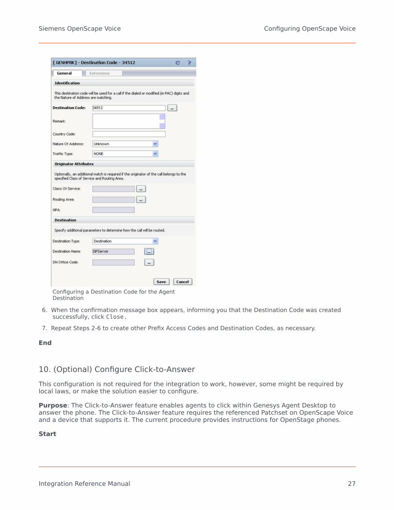
Configuring a Destination Code for the AgentDestination
6. When the confirmation message box appears, informing you that the Destination Code was createdsuccessfully, click Close.
7. Repeat Steps 2-6 to create other Prefix Access Codes and Destination Codes, as necessary.
End
10. (Optional) Configure Click-to-AnswerThis configuration is not required for the integration to work, however, some might be required bylocal laws, or make the solution easier to configure.
Purpose: The Click-to-Answer feature enables agents to click within Genesys Agent Desktop toanswer the phone. The Click-to-Answer feature requires the referenced Patchset on OpenScape Voiceand a device that supports it. The current procedure provides instructions for OpenStage phones.
Start
Siemens OpenScape Voice Configuring OpenScape Voice
Integration Reference Manual 27

1. On the phone that you have to configure, select Configuration.
Selecting Configuration on the OpenStage Phone
2. Click Incoming calls, and then click CTI calls.
Configuring CTI Calls on the OpenStage Phone
3. Select the Allow auto-answer check box, and click Submit.
Submitting Allow auto-answer on the OpenStage Phone
4. Repeat Steps 1-3 for every agent phone on the switch.
End
11. (Optional) Configure emergency call routingThis configuration is not required for the integration to work, however, some might be required bylocal laws, or make the solution easier to configure.
The emergency call routing feature provides alternate call routing in cases in which SIP Server isunavailable, if your local emergency (or 911) laws require some form of alternate routing for agents.
During the first 30 seconds after the emergency calling support is activated, calls will fail to route.After that, OpenScape Voice will route calls via the alternate route that you configure and the callswill work.
Siemens OpenScape Voice Configuring OpenScape Voice
Integration Reference Manual 28
Start
1. Log in to the HiPath Assistant, and navigate to the Business Group of the contact center that you wantto configure—for example, GenesysLab.
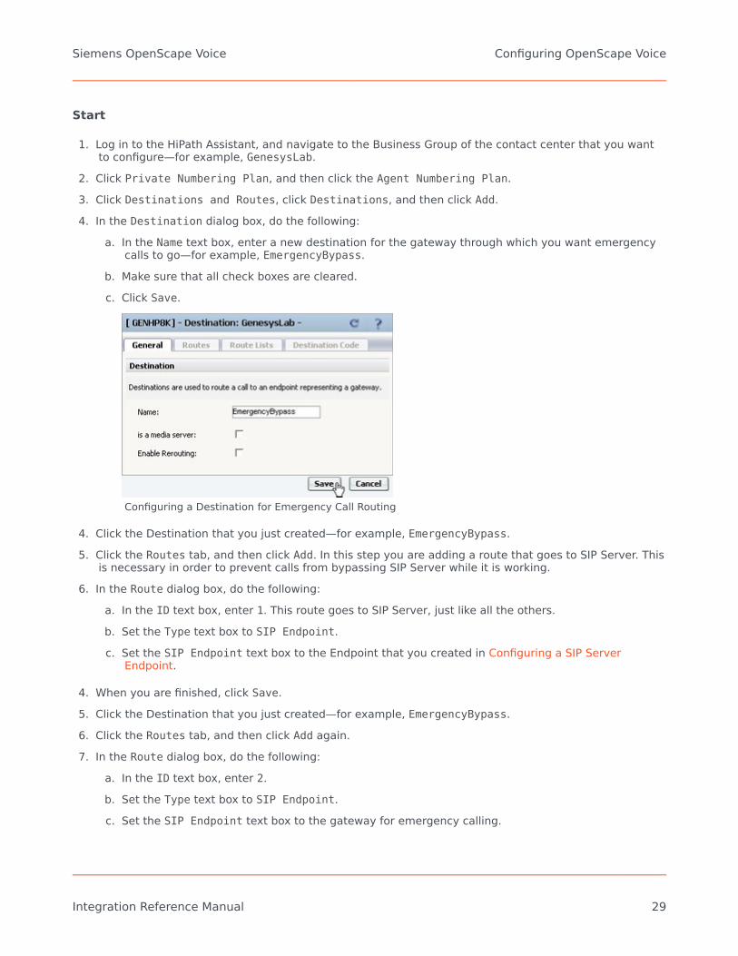
2. Click Private Numbering Plan, and then click the Agent Numbering Plan.3. Click Destinations and Routes, click Destinations, and then click Add.4. In the Destination dialog box, do the following:
a. In the Name text box, enter a new destination for the gateway through which you want emergencycalls to go—for example, EmergencyBypass.
b. Make sure that all check boxes are cleared.c. Click Save.
Configuring a Destination for Emergency Call Routing
4. Click the Destination that you just created—for example, EmergencyBypass.5. Click the Routes tab, and then click Add. In this step you are adding a route that goes to SIP Server. This
is necessary in order to prevent calls from bypassing SIP Server while it is working.6. In the Route dialog box, do the following:
a. In the ID text box, enter 1. This route goes to SIP Server, just like all the others.b. Set the Type text box to SIP Endpoint.c. Set the SIP Endpoint text box to the Endpoint that you created in Configuring a SIP Server
Endpoint.
4. When you are finished, click Save.5. Click the Destination that you just created—for example, EmergencyBypass.6. Click the Routes tab, and then click Add again.7. In the Route dialog box, do the following:
a. In the ID text box, enter 2.b. Set the Type text box to SIP Endpoint.c. Set the SIP Endpoint text box to the gateway for emergency calling.
Siemens OpenScape Voice Configuring OpenScape Voice
Integration Reference Manual 29

d. When you are finished, click Save.
Configuring a Route for Emergency Call Routing
5. Click Prefix Access Codes, and then click Add.6. In the Prefix Access Code dialog box, do the following:
a. In the Prefix Access Code text box, enter the digits for your emergency number.b. Set the Prefix Type text box to Off-net Access.c. Set the Nature of Address text box to Unknown.d. Set the Destination Type text box to None.e. Click Save, and close the dialog box.
Siemens OpenScape Voice Configuring OpenScape Voice
Integration Reference Manual 30

Configuring a Prefix Access Code for Emergency CallRouting
6. In the Prefix Access Code dialog box, click the Destination Codes tab.7. On the General tab, do the following:
a. Make sure that the Destination Type text box is set to Destination.b. Set the Destination Name text box to the Destination that you created in Step 4—for example,
EmergencyBypass—by clicking the browse (...) button.c. When you are finished, click OK.
Siemens OpenScape Voice Configuring OpenScape Voice
Integration Reference Manual 31

Configuring a Destination Code for Emergency CallRouting
End
Next Steps:
• Configuration of OpenScape Voice is now complete. Proceed with Configuring DN Objects.
Siemens OpenScape Voice Configuring OpenScape Voice
Integration Reference Manual 32

Configuring DN ObjectsYou configure DN objects for the OpenScape Voice in the Configuration Layer under the Switch objectthat is assigned to the appropriate SIP Server.
1. Configure a Voice over IP Service DN2. Configure a Trunk DN3. Configure Extension DNs4. Configure Routing Point DNs
1. Configuring a Voice over IP Service DNPurpose: To configure a DN of type Voice over IP Service that specifies the connection andoptions for OpenScape Voice communication with a SIP Server that is running in Application Server(B2BUA) mode.
Start
1. In Configuration Manager, under a configured Switch object, select the DNs folder. From the File menu,select New > DN to create a new DN object.
2. In the New DN Properties dialog box, click the General tab, and then specify the following properties:a. Number: Enter the softswitch name—for example, OpenScape Voice. Although this name is
currently not used for any messaging, it must still be unique.b. Type: Select Voice over IP Service from the drop-down box.
Siemens OpenScape Voice Configuring DN Objects
Integration Reference Manual 33

Creating a Voice over IP Service DN for OpenScapeVoice: Sample Configuration
c. Click the Annex tab.d. Create a section that is named TServer. In the TServer section, create options as specified in the
following table.Option Name Option Value Description
contact <ipaddress>:<SIP port>
The contact URI that SIPServer uses forcommunication with theOpenScape Voice softswitch,where <ipaddress> is the IPaddress of the softswitch and<SIP port> is the SIP portnumber of the softswitch.TLS configuration: use the followingformat: contact =<ipaddress>:<SIPport>;transport=tls
For more information about how toconfigure SIP Server, see theTransport Layer Security for SIP Trafficsection in the SIP Server DeploymentGuide.
dual-dialog-enabled false
Set this option to false ifSiemens phones are used inre-INVITE mode for third-party call-control (3pcc)operations.
Siemens OpenScape Voice Configuring DN Objects
Integration Reference Manual 34

Option Name Option Value Description
makecall-subst-uname 1, or none
For OpenScape Voice version2.1, set this option to 1.ForOpenScape Voice version 2.2and later, do not configurethis option. When this optionis set to 1, SIP Server sets theFrom header to the samevalue as the To header in theINVITE request, to workaround issues with pre-2.2versions of OpenScape Voice.
make-call-rfc3725-flow 1
Set this option to 1.When thisoption is set to 1, SIP Serverselects the SIP call flownumber 1 (described in RFC3725) for a call that isinitiated by a TMakeCallrequest.
refer-enabled false
Set this option to false for SIPServer to use a re-INVITErequest method whencontacting the softswitch. Thisis the only method that issupported in the OpenScapeVoice configuration.
ring-tone-on-make-call true
When this option is set totrue, SIP Server connects thecaller with an audio ringtonefrom Stream Manager whenthe destination endpointresponds with a 180 Ringingmessage.
service-type softswitch Set this option to softswitch.
sip-cti-control talk
When this option is set totalk, SIP Server instructs theendpoint to go off-hook bysending a SIP NOTIFYmessage with the Event:talk header. This enables aTAnswerCall request to besent to SIP Server. SIP Serverthen sends the NOTIFYmessage to the switch.Setting this option to talksets the default for allendpoints that are configuredwith this softswitch.The talkvalue is supported only onOpenScape Voice version 2.2Patchset 14 or later.Note: You must also configureOpenScape Voice to support this
Siemens OpenScape Voice Configuring DN Objects
Integration Reference Manual 35

Option Name Option Value Description
functionality. See Configuring Click-to-Answer.
sip-ring-tone-mode 1
When this option is set to 1,SIP Server waits for aresponse from the calleddevice, and connects StreamManager to a call to play anaudio ring tone only when thereturned response cannot beused as the offer to a callingdevice.
e. When you are finished, click Apply.
Setting Options for a Voice over IP Service DN:Sample Configuration
End
2. Configuring a Trunk DNPurpose: To configure a DN of type Trunk that specifies how SIP Server handles outbound calls.It is also used for configuration of gateways, SIP proxies (including connections to other instancesof SIP Server), and other SIP-based applications. From the SIP Server perspective, OpenScapeVoice in Application Server (B2BUA) mode is considered a gateway or SIP proxy.
Start
1. Under a configured Switch object, select the DNs folder. From the File menu, select New > DN tocreate a new DN object.
2. In the New DN Properties dialog box, click the General tab, and then specify the followingproperties:a. Number: Enter a name for the Trunk DN. This name can be any unique value, and it can be a
combination of letters and numbers.b. Type: Select Trunk from the drop-down box.
Siemens OpenScape Voice Configuring DN Objects
Integration Reference Manual 36

Creating a Trunk DN for OpenScape Voice: Sample Configuration
3. Click the Annex tab.4. Create a section that is named TServer. In the TServer section, create options as specified in the
following table.Option Name Option Value Description
contact <ipaddress>:<SIP port>
The contact URI that SIPServer uses forcommunication with theOpenScape Voice softswitch,where <ipaddress> is the IPaddress of the softswitch and<SIP port> is the SIP portnumber of the softswitch.
prefix Any numerical string
The initial digits of the numberthat SIP Server matches todetermine whether this trunkshould be used for outboundcalls. For example, if prefixis set to 78, dialing a numberthat starts with 78 will causeSIP Server to consider thistrunk a gateway or SIP proxy.If multiple Trunk objectsmatch the prefix, SIP Serverwill select the one that hasthe longest prefix thatmatches.
refer-enabled false Set this option to false for SIP
Siemens OpenScape Voice Configuring DN Objects
Integration Reference Manual 37

Option Name Option Value DescriptionServer to use a re-INVITErequest method whencontacting the softswitch. Thisis the only method that issupported in the OpenScapeVoice configuration.
replace-prefix Any numerical string
The digits (if necessary) thatreplace the prefix in the DN.For example, if prefix is setto 78, and replace-prefix isset to 8, the number786505551212 will bereplaced with 86505551212before it is sent to thegateway or SIP proxy (in thiscase, OpenScape Voice).
Setting Options for a Trunk DN: Sample Configuration
5. When you are finished, click Apply.
End
3. Configuring Extension DNsPurpose: To configure DNs of type Extension that represent agent phone extensions andregister directly with the softswitch.
When you configure an extension where the phone registers directly with SIP Server, you mustconfigure options in the TServer section on the Annex tab. However, if you are using a softswitchin Application Server (B2BUA) mode, SIP Server takes the Extension DN name together with thevalue of the contact option in the softswitch object configuration (not the Extension object) toaccess the phone. This procedure describes the configuration for phones that are registereddirectly with OpenScape Voice and not with SIP Server. As a result, SIP Server sends the requestto OpenScape Voice to communicate with the phone.
Start
1. Under a configured Switch object, select the DNs folder. From the File menu, select New > DN tocreate a new DN object.
Siemens OpenScape Voice Configuring DN Objects
Integration Reference Manual 38

2. In the New DN Properties dialog box, click the General tab, and then specify the followingproperties:a. Number: Enter a name for the Extension DN. In general, this should be the 10-digit phone
number of the extension. You must not use the @ symbol or a computer name. The name ofthis DN must map to the SIP user name of the extension in OpenScape Voice.
b. Type: Select Extension from the drop-down box.
Creating an Extension DN for OpenScape Voice: Sample Configuration
c. When you are finished, click Apply.Note: No configuration options are required for the Extension DN. Adding configuration options—such as contact,password, refer-enabled, and others—might cause unexpected results.
End
4. Configuring Routing Point DNsPurpose: To configure a DN of type Routing Point that is used to execute a routing strategywith Genesys URS. When SIP Server receives an INVITE request on a DN that is configured as aRouting Point, it sends an EventRouteRequest message to URS.
Start
1. Under a configured Switch object, select the DNs folder. From the File menu, select New > DN tocreate a new DN object.
2. In the New DN Properties dialog box, click the General tab, and then specify the followingproperties:
Siemens OpenScape Voice Configuring DN Objects
Integration Reference Manual 39

a. Number: Enter a number for the Routing Point DN. This number must be configured onOpenScape Voice.
b. Type: Select Routing Point from the drop-down box.
Creating a Routing Point for OpenScape Voice:Sample Configuration
c. When you are finished, click Apply.
Although no configuration options are required for the Routing Point, URSdoes look at options to determine how to handle the Routing Point andwhat strategy is currently loaded. For details about these options, see theGenesys 8.x Universal Routing Server Reference Guide.
End
Siemens OpenScape Voice Configuring DN Objects
Integration Reference Manual 40

Support for First-Party Call-ControlOperationsBeginning with the Siemens OpenScape Voice switch release V5, SIP Server provides support for first-party call-control (1pcc) operations, including a transfer that uses the REFER method when it isintegrated with the OpenScape Voice softswitch.
Feature Configuration
To support 1pcc operations, you must configure a DN of type Voice over IP Service DN andExtension DNs. See Configuring DN Objects for details.
To enable a blind transfer, set the blind-transfer-enabled configuration option to true, at the SIPServer Application level, or at the Voice over IP Service DN level.
Feature Limitations
There are several known limitations that result from the Siemens OpenScape Voice release V5integration:
• Mix of 1pcc and 3 pcc with a call is not supported.• For 3 pcc calls, the re-INVITE--based call control method is used.
Siemens OpenScape Voice Support for First-Party Call-Control Operations
Integration Reference Manual 41

Support for Split-Node DeploymentsThe Siemens OpenScape PBX can be configured to operate in a SIP Business Continuity configuration.There are two supported modes:
• High-availability pair configuration, in which two OpenScape Voice nodes are physically located in thesame area and share the same IP address for initiating and receiving calls.
• Split-node configuration, in which each OpenScape Voice node is geographically separated from theother. In this configuration, each PBX node has its own IP address on different subnets. Each node canbe active for certain DNs; so, when a failure occurs, the remaining node will handle all calls, withouttaking over the IP address of the failed node.
Previous deployments of SIP Server with OpenScape Voice utilized only the first mode. Beginning withrelease 8.1, SIP Server supports a split-node configuration.
In a split-node configuration of the OpenScape Voice (with the same SIP Server), each OpenScapeVoice node has a different IP address on different subnets. When both nodes are active, calls fromeach node arrive at SIP Server (typically, each node handles a subset of DNs). SIP Server recognizesall calls as coming from the same switch, as both nodes are part of the same OpenScape Voiceswitch.
When one of the OpenScape Voice nodes fails, the remaining node takes over all existing and futurecalls. SIP Server will handle existing and future calls to and from the remaining node, which has adifferent IP address on a different subnet. This take-over process will be transparent to endpoints(which are registered at the OpenScape Voice switch and will be re-registered at the remaining nodein case of failure), to agents, and to Genesys T-Library client applications. See the Split-NodeDeployment figure.
Split-Node Deployment
Siemens OpenScape Voice Support for Split-Node Deployments
Integration Reference Manual 42

Configuring Split-Node deployment
To support the split-node configuration, all OpenScape Voice (or PBX) nodes are represented in theconfiguration environment as a single Voice over IP Service object with the service-type optionset to softswitch.
All PBX nodes share the same FQDN, which could be resolved through the DNS SRV records. DNS SRVrecords must be administered in such a way that the IP address of the node, in which endpoints areregistered by default, has the highest priority. SIP Server tests the availability of all resolvedaddresses by using OPTION requests. The available address with the highest priority is used for SIPcommunication. If the original node fails, endpoints are re-registered at an alternative node. SIPServer starts using the alternative node when it discovers that the original node is not available.
Configuration steps:
1. Configure each SIP Server. In the SIP Server Application object, in the TServer section, configure thefollowing options:• sip-enable-gdns—Set this option to true. This enables the internal DNS client.• sip-address—Set this option to the IP address of the SIP Server host computer (not the URI).• sip-address-srv—Set this option to the FQDN of the SIP Server host computer. SIP Server will send
this address as its own contact inside SIP requests to the PBX.
2. Configure the Voice over IP Service DN:• service-type—Set this to softswitch.• contact—Specify the FQDN of Siemens PBX. The FQDN must be resolvable by DNS SRV records.• oos-check—Specify the time interval, in seconds, in which SIP Server will send OPTION requests to
transport addresses returned by DNS SRV resolution. SIP Server will send an OPTION request bytransport for those addresses at which active SIP communication is not present.
• oos-force—Specify the time interval, in seconds, in which SIP Server will mark the transportaddress as unavailable when there is no response to the OPTION request. This configuration optionapplies only if the configuration option oos-check is set to a non-zero value.
See also the following configuration options for this softswitch DN.
3. Configure Extension DNs by completing the following procedure:• Procedure: Configuring Extension DNs
4. (Optional) Configure a Trunk DN for SIP Server to handle outbound calls with the following option:• contact=<FQDN of Siemens PBX>—This is the same value as configured on the softswitch DN.
Feature Limitations
Verification of split-node functionality was done with geographically-separated nodes that wereconfigured without RG8700 as a SIP Proxy Server.
Siemens OpenScape Voice Support for Split-Node Deployments
Integration Reference Manual 43

Handling Call Forwarding LoopIn a SIP Server deployment with the Unified OpenScape Voice platform, you can configure SIP Serverto support call forwarding from a back office phone to an agent phone, without creating an extra T-Library call in SIP Server.
Feature Configuration
Set the sip-enhance-diversion option to true.
sip-enhance-diversion
Setting: TServer section, Application levelDefault Value: falseValid Values: false, trueChanges take effect: For the next call
Specifies how SIP Server processes an INVITE message based on the value of the Diversion header. Ifthe option is set to true and the Diversion header references the call forwarding party, SIP Serverrejects that INVITE, waits until that rejection is propagated by the PBX back to the SIP Server in theoriginal SIP dialog, and sends a new INVITE message to a forwarding destination.
Feature Limitations
This feature does not apply to the scenario in which an external number is forwarding multiple callsback to SIP Server simultaneously.
Siemens OpenScape Voice Handling Call Forwarding Loop
Integration Reference Manual 44

Cisco Unified Communications ManagerGenesys SIP Server is a key integration point between the Genesys Customer Experience Platformand Cisco Unified Communications Manager (CUCM). The integration supports several capabilities:
• In-Front Qualification & Parking provides centralized queuing & qualification (basic IVR), beforerouting calls to an agent. (See the T-Server for Cisco Unified Communications Manager DeploymentGuide for details.)
• Advanced Self Service integrates Genesys Voice Platform with advanced VXML, ASR, TTS (and more)to CUCM.
• Manage Agent-related Calls allows agents to utilize CUCM as the underlying telephony platform,while SIP Server manages calls & agent state. This is an effective alternative to the standard JTAPI-based T-Server integration.
• Recording Integration integrates with Genesys Interaction Recording or the Genesys RecordingConnector.
You can deploy any combination of these capabilities. For instance, In-Front Qualification & Parkingcould be deployed in conjunction with the JTAPI-based T-Server. Or a pure SIP deployment couldutilize In-Front Qualification & Parking, and SIP-based agent management.
The configuration for Genesys SIP Server, as it relates to the CUCM integration, is largely the samefor most of these capabilities.
It contains the following sections:
• Managing Agents over SIP• Configuring CUCM• Configuring DN Objects
Note: The instructions on the following pages in this topic assume that both CUCM and SIP Serverare fully functional as stand-alone products. The instructions only highlight modifications to theexisting configuration to make these products work as an integrated solution.
See supported CUCM versions in the Supported Media Interfaces Guide.
Cisco Unified Communications Manager Handling Call Forwarding Loop
Integration Reference Manual 45

Managing Agents over SIP
Overview of SIP-based Integration for Managing Agents
Genesys SIP Server supports operation as a type of “Application Server.” Effectively, agents will havetheir telephone service (dial tone) provide by a phone which is part of a Cisco UCM deployment. SIPServer will serve as the application server which manages contact center calls to and from theagents. This integration utilizes a SIP Trunk between the two components, and typically involves anexchange of presence information for each DN. The presence information informs SIP Server when anagent is involved in a non-contact center call, and this status is taken into account when the GenesysURS/ORS routing components select an agent (such as not routing a contact center call to an agentwho is already busy).
This SIP-based integration offers several key benefits:
• Standards based integration using the SIP protocol.• Fewer components—SIP Server is often deployed for purposes of recording or qualification & parking,
and extending it to manage agents requires nothing more than configuration updates. This benefit isalso valuable in case it is not practical to deploy a dedicated JTAPI-based T-Server (such as when CiscoUCM is geographically distant from the Genesys infrastructure).
• Access to unique features provided by SIP Server—such as full support of Genesys InteractionRecording, Personal Greetings for agents, support of Genesys SIP Voicemail.
The SIP-based integration does have some limitations which will be visible to the agents:
• First-Party Call Control (1PCC) Limitations—Agents are not allowed to use their phone for initiating mid-call changes like hold/retrieve, conference or transfer. These operations must be initiated using theagent desktop application.
• Third-Party Call Control (3PCC) Limitations—SIP Server does not have complete control over the phone,so some 3PCC operations are not supported; the main 3PCC operation which is missing is Click-to-answer (the agent must manually answer each call, or they must set the phone to “auto answer” eachincoming call).
Deployment Architecture
SIP Server is integrated with CUCM via SIP trunks.The figure below depicts a sample deploymentarchitecture of SIP Server with CUCM.
Cisco Unified Communications Manager Managing Agents over SIP
Integration Reference Manual 46

This sample call flow describes the steps for an incoming call handled by the CUCM–SIP Serverintegration solution:
1. Genesys SIP Server is monitoring the status of each agent’s phone.2. An incoming customer call arrives at CUCM.3. CUCM delivers the call to SIP Server via a configured SIP Trunk.4. Genesys SIP Server (typically) uses a routing strategy on URS/ORS which selects a qualified agent who
is in the Ready state, or places the call in queue until an agent is available. Direct calls to an agent arealso possible if the agent has a Direct Inward Dial (DID) phone number.
5. SIP Server delivers the call to CUCM via a SIP trunk (if multiple SIP trunks are defined, the selection isconfigurable as round-robin or primary/backup).
6. CUCM delivers the call to the agent’s phone and the agent answers the call.The agent will use their desktop application (connected to SIP Server) for all mid-call operations, suchas transfer, conference, supervision, recording control, and hold/retrieve.
7. The call disconnects when the caller or the agent hangs up.
Call Flows
Subscription
Genesys SIP Server integration with CUCM relies on the SUBSCRIBE/NOTIFY feature that is supportedby CUCM.
• At startup, SIP Server sends subscription messages for a device or a list of configured devices to benotified about the endpoints status change.
• CUCM provides NOTIFY messages to SIP Server according to the endpoints status. As soon as anendpoint registers with CUCM, CUCM sends a NOTIFY message to SIP Server with the status reported asactive.
Cisco Unified Communications Manager Managing Agents over SIP
Integration Reference Manual 47
Private Calls
A CUCM dialing plan can be set up in such a way that private calls (direct calls to an agent, forexample) are not forwarded to SIP Server. Instead, only the notification about the busy status of theendpoint is passed to SIP Server.
SIP Server uses this status change notification to set the endpoint DN to a busy state(EventAgentNotReady), so that the rest of the Genesys suite will not consider that DN available forthe routing of contact center calls. As soon as the call is released at the endpoint, CUCM notifies SIPServer, which then generates an EventAgentReady message. The agent is then considered availablefor contact center calls.
The mechanism for private outbound call processing is exactly the same. SIP Server receives theNOTIFY messages sent by CUCM.
Contact Center Calls
In the same way that you can set up a CUCM dialing plan to bypass SIP Server for private calls, youcan write rules governing how CUCM connects contact center calls (typically, calls to the servicenumber of the company) to SIP Server.
After connection, SIP Server triggers a strategy for Universal Routing Server (URS) to process thistype of call. Eventually, an agent DN is selected to handle the customer call and SIP Server initiates anew dialog to CUCM for the selected endpoint.
Finally, CUCM delivers the call to the agent endpoint. This mechanism creates a signaling loop insideSIP Server, which is then in charge of maintaining the inbound leg from CUCM (customer leg) with theoutbound leg to CUCM (agent leg).
By staying in the signaling path, SIP Server detects any change in call status, and generates call-related events (EventRinging, EventEstablished, EventReleased, and so on).
Any call control operation from the agent must be performed using a third-party call control (3pcc)procedure. In other words, the agent desktop must be used for any call control operation (except theanswer call operation). This includes, but is not limited to, hold, transfer, and conference requests.
If a Network/Media Gateway is directly connected to SIP Server, then contact center calls are firstreceived by SIP Server. The call flow for routing the call is very similar to the flow described above,except that there is only one call leg in CUCM.
Conferences
SIP Server supports conferences for agents on CUCM. A conference is initiated by a T-Library client(for example, Workspace Desktop). SIP Server can be configured to use either Media Server or otherthird-party MCUs to provide the conferencing feature.
Call Supervision
Supervisor features—such as, Silent-Monitoring and Barge-In—are also supported for this integrationwith CUCM. Supervisor functionality is supported via a T-Library interface. SIP Server includes asupervisor in a call between a customer and an agent (conference) and signals Media Server to eitherkeep the supervisor media leg open for two-way media (sendrecv - Barge-In) or one way (for SilentMonitoring).
Cisco Unified Communications Manager Managing Agents over SIP
Integration Reference Manual 48

Presence
Genesys needs to be aware of non-contact center calls (and a general phone status), to make thebest contact center routing decisions. SIP Server SUBSCRIBEs towards CUCM for presence informationper RFC 3856, and CUCM NOTIFYs of the device state. SIP Server maps this presence information tothe agent/device state in the Genesys T-Library model.
SIP Server transforms notifications about presence state changes into the Agent State updates,according to the following rules:
• For the initial NOTIFY with a basic status Open:• SIP Server uses the initial NOTIFY message to generate EventAgentLogin and EventAgentReady
messages.
• For subsequent NOTIFY messages with the basic status Open:• SIP Server checks whether an agent is logged in. If not, SIP Server sends an event that the agent
has logged in (EventAgentLogin).• SIP Server checks whether any activity is indicated in presence notification. If not, and if the agent is
in the Not Ready state, SIP Server sends an event that the agent is Ready (EventAgentReady).• If an activity is indicated in the presence notification, and if the agent is Ready, SIP Server sends an
event that the agent is not Ready (EventAgentNotReady), attaching the activity from the presencenotification as a ReasonCode.
• For presence notification with the basic status Closed is received:• SIP Server checks whether the agent is logged in. If yes, SIP Server sends an event that the agent
has logged out (EventAgentLogout).
In NOTIFY messages from CUCM, when an agent is handling a direct in-dial call, SIP Server expects aSIP NOTIFY message with the basic status Open and activities as "on-the-phone". Note that the Ciscoextension must be set to allow for call waiting. If the extension is not configured to allow call waiting,then whenever the agent is handling a direct in-dial call, Cisco will send a SIP NOTIFY message withthe basic status Closed and activities as "on-the-phone".
Agent States through SIP Presence and T-Library Interface
While working with CUCM, SIP Server could modify agent states based on two different inputs:
• NOTIFY message within a SUBSCRIBE dialog• T-Library client requests from the agent desktop
Such dualism could lead to conflict unless some priority rules are applied. SIP Server alwaysconsiders a message that brings an agent in the Not Ready/Logout state of the higher priority over amessage that brings an agent in the Logging/Ready state coming from a different interface.
Endpoint Support
The SIP-based integration between SIP Server and CUCM works for all known endpoints includingCisco IP Communicator and Cisco Hardphones (with a minor disclaimer that only a select few phoneswere actually tested, but all had positive results). With IP communicator CUCM sends NOTIFY with theOpen state when it starts, so SIP Server can set an agent linked to this extension in the Login/Ready
Cisco Unified Communications Manager Managing Agents over SIP
Integration Reference Manual 49

state. At proper exit of IP Communicator, CUCM sends NOTIFY with the terminated state, so SIPServer sets an agent in the Logout state.
Supported Versions
For supported CUCM versions, see the Genesys Supported Media Interfaces Guide SupportedInfrastructure page.
Integration Task Summary
To integrate SIP Server with CUCM, complete the following procedures:
1. Configure CUCM.2. Configure DN objects for CUCM.
Cisco Unified Communications Manager Managing Agents over SIP
Integration Reference Manual 50

Configuring CUCMThis is an overview of the main steps that are required to configure CUCM. Refer to the Cisco UnifiedCommuncations Manager documentation for standard configuration procedures.
1. Configure Cisco Phones to point to CUCM. Genesys SIP Server currently supports this integration withonly SIP Phones that are compatible with CUCM.
2. Ensure that the Service Parameter Configuration for the [server-name], the Clusterwide parameters(System – Presence) for Default Inter-Presence Group Subscription is set to AllowSubscription.
3. Ensure that the SIP Trunk Security Profile > Outgoing Transport Type is set to UDP, and theAccept Presence Subscription checkbox is selected.
4. Build a SIP Trunk to point it to the SIP Server host using the SIP Trunk Security Profile configured in theprevious step, with an appropriate Inbound Calling Search Space and SUBSCRIBE Calling SearchSpace.
Note: If a Presence Group is added to segregate resources, the SIP trunk and all appropriateresources must be in the same Presence Group, and resources must also share the same SUBSCRIBECalling Search Space.
Cisco Unified Communications Manager Configuring CUCM
Integration Reference Manual 51

Configuring DN ObjectsYou configure Genesys DN objects to represent CUCM in the Configuration Layer under the Switchobject that is assigned to the appropriate SIP Server.
1. Configure a Voice over IP Service DN.
For each CUCM SIP Trunk present in the cluster, create a DN object of type Voice over IP Service.Configure the following options in the TServer section for such object.
Option Name Option Value Description
contact SIP URISpecify the contact URI that SIPServer uses for communicationwith CUCM.
dual-dialog-enabled falseSet this option to false toinstruct SIP Server not to createnew a SIP dialog when making aconsultation call.
enable-agentlogin-presence trueSet this option to true for SIPServer to provide accurateinformation about agent states.
make-call-rfc3725-flow 1
Set this option to 1, so SIP Serverselects the SIP call flow number 1(described in RFC 3725) for a callthat is initiated by a TMakeCallrequest.
oos-checkSpecify how often (in seconds)SIP Server checks a device forout-of-service status.
oos-force
Specify the time interval (inseconds) that SIP Server waitsbefore placing a device that doesnot respond in out-of-servicestate when the oos-check optionis enabled.
refer-enabled falseSet this option to false for SIPServer to use a re-INVITErequest method when contactingCUCM.
service-type softswitch Set this option to softswitch.
Cisco Unified Communications Manager Configuring DN Objects
Integration Reference Manual 52

2. Configure a Trunk DN.
Create a DN of type Trunk with the name, for example, CUCMTrunk. Create a section that is namedTServer. In the TServer section, create options as specified in the following table.
Option Name Option Value Description
contact SIP URI
Specify the contact URI that SIPServer uses for communicationwith CUCM. If there is a clusterCUCM deployment, specify theaddress of any CUCM.
contact-backup SIP URI
(For CUCM cluster only) Maycontain a comma-separated listof addresses of other membersof the CUCM cluster. In case of asingle node CUCM deployment,this option must not beconfigured.
oos-checkSpecify how often (in seconds)SIP Server checks a device forout-of-service status.
oos-force
Specify the time interval (inseconds) that SIP Server waitsbefore placing a device that doesnot respond in out-of-servicestate when the oos-check optionis enabled.
subscribe-presence-domain Any valid domain
Specify the subscription domaininformation for the Trunk DN.This option value is used with theDN name to form the SUBSCRIBErequest URI and the To header.
subscribe-presence-from SIP URI
Specify the subscription endpointinformation. This option value isused to form the From header inthe SUBSCRIBE request to CUCM.This must be the same addressas the SIP Server host that is partof the SIP trunk configuration inCUCM.
subscribe-presence-expire Specify the subscription renewalinterval (in seconds).
3. Configure Extension DNs.
Enable a presence subscription for the Extension DNs by specifying the option subscribe-presence.This option's value must be the name of the Trunk DN that contains subscription parameters—for
Cisco Unified Communications Manager Configuring DN Objects
Integration Reference Manual 53

example, CUCMTrunk.
Extension DN objects...
• ...must not have any other options configured.• ...must not have the option contact configured.• ...must be created for all DNs used as agent phones.
4. Create Agent IDs.
Create Agent IDs for all Extension DNs with the subscription enabled. The Agent ID must be same asthe ID of the DN of type Extension.
Cisco Unified Communications Manager Configuring DN Objects
Integration Reference Manual 54

Cisco Media GatewayThis section describes how to integrate SIP Server with the Cisco Media Gateway Controller (MGC). Itcontains the following sections:
• Overview• Configuring Cisco Media Gateway• Configuring DN Objects
Note: The instructions in this section assume that the Cisco Media Gateway is fully functional.
Cisco Media Gateway Configuring DN Objects
Integration Reference Manual 55

SIP Server and Cisco Media GatewayIntegration OverviewThe SIP Server and Cisco Media Gateway integration solution described in this topic is not the onlymethod that will work. Although there are other methods, this is the only one that has been testedand approved by Genesys, and that is supported by Genesys Customer Support.
The following Cisco IOS Software versions were tested:
• 2800 Series• 3700 Series• 3800 Series• 5300 Series• 5400 Series
For confirmation of the supported Cisco IOS Software versions, contact Genesys Technical Support.For more information about Cisco IOS Software, go to the Cisco web site at http://www.cisco.com/.
Deployment Architecture
The following figure depicts a sample deployment architecture of SIP Server with Cisco MediaGateway.
SIP Server - Cisco Media Gateway Deployment Architecture
Cisco Media Gateway SIP Server and Cisco Media Gateway Integration Overview
Integration Reference Manual 56

Integration Task Summary
To integrate SIP Server with Cisco Media Gateway, complete the following procedures:
1. Configure Cisco Media Gateway.
2. Configure a Trunk DN for Cisco Media Gateway.
Cisco Media Gateway SIP Server and Cisco Media Gateway Integration Overview
Integration Reference Manual 57

Configuring Cisco Media GatewayThis page provides an overview of the main steps that are required to configure Cisco MediaGateway.
Integrating with Cisco Media Gateway
1. Check Prerequisites.
Verify that Cisco Media Gateway is working
Verify that Cisco Media Gateway is functional and handling calls appropriately.
The procedures in this topic assume that Cisco Media Gateway is functional and handling callsappropriately. For more information, see Cisco Media Gateway-specific documentation.
2. Configure an E1 environment.
Configuring an E1 environment
Purpose
To configure an E1 environment. This section provides an example of an E1 configuration.
Start
1. Configure a controller:controller E1 0/2/0framing NO-CRC4ds0-group 0 timeslots 1 type fxo-loop-startds0-group 1 timeslots 2 type fxo-loop-startds0-group 2 timeslots 3 type fxo-loop-start
2. Configure voice ports:voice-port 0/2/0:0output attenuation 0station-id name 2300090voice-port 0/2/0:1output attenuation 0station-id name 2300091
Cisco Media Gateway Configuring Cisco Media Gateway
Integration Reference Manual 58

voice-port 0/2/0:2output attenuation 0station-id name 2300092
3. Configure dial peers:dial-peer voice 2300090 potsdestination-pattern 6...supplementary-service pass-throughport 0/2/0:0forward-digits alldial-peer voice 2300091 potsdestination-pattern 6...supplementary-service pass-throughport 0/2/0:1forward-digits alldial-peer voice 2300092 potsdestination-pattern 6...supplementary-service pass-throughport 0/2/0:2forward-digits alldial-peer voice 8800 voipservice sessiondestination-pattern 8800voice-class codec 4session protocol sipv2session target ipv4:192.168.50.137dtmf-relay rtp-ntesupplementary-service pass-through
End
Next Steps
• Configuring a T1 CAS environment
3. Configure a T1 CAS environment.
Configuring a T1 CAS environment
Purpose
To configure a T1 CAS environment. This section provides an example of a T1 CAS configuration.
Start
1. Configure a controller:controller T1 1/0/1framing sfclock source internal
Cisco Media Gateway Configuring Cisco Media Gateway
Integration Reference Manual 59

linecode amids0-group 0 timeslots 1 type e&m-immediate-startds0-group 1 timeslots 2 type e&m-immediate-startds0-group 2 timeslots 3 type e&m-immediate-start
2. Configure voice ports:voice-port 0/2/0:0output attenuation 0station-id name 2300090voice-port 0/2/0:1output attenuation 0station-id name 2300091voice-port 0/2/0:2output attenuation 0station-id name 2300092
3. Configure dial peers:dial-peer voice 2300090 potsdestination-pattern 6...supplementary-service pass-throughport 0/2/0:0forward-digits alldial-peer voice 2300091 potsdestination-pattern 6...supplementary-service pass-throughport 0/2/0:1forward-digits alldial-peer voice 2300092 potsdestination-pattern 6...supplementary-service pass-throughport 0/2/0:2forward-digits alldial-peer voice 8800 voipservice sessiondestination-pattern 8800voice-class codec 4session protocol sipv2session target ipv4:192.168.50.137dtmf-relay rtp-ntesupplementary-service pass-through
End
Next Steps
• Configuring a T1 PRI environment
4. Configure a T1 PRI environment.
Cisco Media Gateway Configuring Cisco Media Gateway
Integration Reference Manual 60

Configuring a T1 PRI environment
Purpose
To configure a T1 PRI environment. This section provides an example of a T1 PRI configuration.
Start
1. Configure a controller:controller T1 0/0/0framing esflinecode b8zspri-group timeslots 1-24
2. Configure an interface serial:interface Serial0/0/0:23no ip addressencapsulation hdlcisdn switch-type primary-niisdn incoming-voice voiceno cdp enable
3. Configure a voice port:voice-port 0/0/0:23
4. Configuring dial peers:dial-peer voice 9 potsdestination-pattern 9Tincoming called-number 9...port 0/0/0:23dial-peer voice 8800 voipservice sessiondestination-pattern 8800voice-class codec 4session protocol sipv2session target ipv4:192.168.50.137dtmf-relay rtp-ntesupplementary-service pass-through
End
Next Steps
• Configuring an E1 PRI environment
5. Configure an E1 PRI environment.
Cisco Media Gateway Configuring Cisco Media Gateway
Integration Reference Manual 61

Configuring an E1 PRI environment
Purpose
To configure an E1 PRI environment. This section provides an example of an E1 PRI configuration.
Start
1. Configure a controller:controller E1 0/2/1framing NO-CRC4pri-group timeslots 1-31
2. Configure an interface serial:interface Serial0/2/1:15no ip addressencapsulation hdlcisdn switch-type primary-net5isdn protocol-emulate networkisdn incoming-voice voiceno cdp enable
3. Configure a voice port:voice-port 0/2/1:15
4. Configure dial peers:dial-peer voice 130 potsdestination-pattern 130Tdirect-inward-dialport 0/2/1:15dial-peer voice 8800 voipservice sessiondestination-pattern 8800voice-class codec 4session protocol sipv2session target ipv4:192.168.50.137dtmf-relay rtp-ntesupplementary-service pass-through
End
Next Steps
• Configuring a SIP User Agent
6. Configure a SIP User Agent.
Cisco Media Gateway Configuring Cisco Media Gateway
Integration Reference Manual 62

Configuring a SIP User Agent
Purpose
To configure a SIP User Agent. This section provides an example of a SIP User Agent configuration.
Start
Configure a SIP User Agent: enter global configuration "configure terminal":sip-uatimers notify 400sip-server dns:host.genesyslab.com
End
Cisco Media Gateway Configuring Cisco Media Gateway
Integration Reference Manual 63

Configuring DN ObjectsConfigure a Trunk DN for Cisco Media Gateway under the Switch object associated with SIP Server inthe Configuration Layer.
Configuring a Trunk DN for Cisco Media GatewayStart
1. Under a configured Switch object, select the DNs folder. From the File menu, select New > DN to createa new DN object.
2. In the New DN Properties dialog box, click the General tab, and then specify the following properties(see the following figure):a. Number: Enter the gateway name.b. Type: Select Trunk from the drop-down box.
3. Click the Annex tab.4. Create a section named TServer. In the TServer section, create options as specified in the following
table.
Option Name Option Value Description
contact <ipaddress>:<SIP port>
The contact URI that SIP Serveruses for communication withthe gateway, where<ipaddress> is the IP addressof the gateway and <SIP port>is the SIP port number of thegateway.
oos-check 0-300How often (in seconds) SIPServer checks a DN for out-of-service status.
oos-force 0-30How long (in seconds) SIPServer waits before placing aDN out of service.
prefix Any numerical string
The initial digits of the numberthat SIP Server matches todetermine whether this trunkshould be used for outboundcalls. For example, if prefix isset to 78, dialing a numberstarting with 78 will cause SIPServer to consider this trunk agateway or SIP proxy. If multipleTrunk objects match the prefix,SIP Server will select the onewith the longest prefix that
Cisco Media Gateway Configuring DN Objects
Integration Reference Manual 64

Option Name Option Value Description
matches.
priority Any non-negative integer
The gateway priority that SIPServer uses to decide a route. Asmaller number designateshigher priority. If more than onegateway with the same prefix isselected, the gateway withhighest priority is normallyselected. This priority optionis used to control primary-backup gateway switchover,and to provide lowest-costrouting.
refer-enabled false
Set this option to false for SIPServer to use a re-INVITErequest method whencontacting the gateway. This isthe only method supported inthe Cisco Media Gatewayconfiguration.
recovery-timeout 0-86400The length of time that a deviceis set to out-of-service in caseof an error.
replace-prefix Any numerical string
The digits that replace theprefix in the DN. For example, ifprefix is set to 78, andreplace-prefix is set to 8, thenumber 786505551212 will bereplaced with 86505551212before it is sent to the gatewayor SIP proxy (here, Cisco MediaGateway).
5. When you are finished, click Apply.
End
Cisco Media Gateway Configuring DN Objects
Integration Reference Manual 65

F5 Networks BIG-IP LTMThis document describes how to integrate SIP Server with the F5 Networks BIG-IP Local TrafficManager (hereafter referred to as BIG-IP LTM) to support SIP Server hot standby high-availability(HA) mode. It contains the following sections:
• Overview• Configuring SIP Server HA• Configuring BIG-IP LTM• Configuring TLS• Deployment Architecture Example
Note: The instructions in this document assume that BIG-IP LTM is fully functional. They also assumethat Genesys SIP Server has already been installed and configured to function properly.
F5 Networks BIG-IP LTM Configuring DN Objects
Integration Reference Manual 66

SIP Server and BIG-IP LTM IntegrationOverviewThe SIP Server and BIG-IP LTM integration solution described in this document enables you topreserve SIP sessions between SIP Server and other SIP-enabled devices that are involved in contactcenter operations, in switchover scenarios.
In this integration solution, one Virtual Server configured on the BIG-IP LTM is associated with a singleIP address (referred to as Virtual IP address), and it represents one HA pair of SIP Servers configuredas members of one server pool that is associated with the Virtual Server.
Integration Solution Notes
• UDP, TCP, or TLS can be used as the transport for SIP signaling.• Up-front load balancing via Network SIP Server or other device could be implemented, but is not
described in this document.• Configuration of BIG-IP High Availability is not described in this document and has not been validated
with SIP Server.• BIG-IP LTM can be configured in a more complex load-balancing role. This is beyond the scope of this
document.
Supported VersionsThe integration solution described in this document supports the following software versions:
Software Version
Genesys SIP Server8.1.100.98 and later8.1.001.22 and later (does not support TLS/Active-Active RM)
Genesys Voice Platform 8.1.7 and later (required for TLS/Active-Active RM)
F5 BIG-IP Local Traffic Manager BIG-IP v11.x (v11.1.0 Build 1943.0 Final or later),BIG-IP v12.x
Deployment Architecture
The figure below depicts the architecture of a sample deployment of primary and backup SIP Serverswith the BIG-IP LTM, in which:
• BIG-IP LTM is positioned as a network router between a SIP Server HA pair and other network entities.• Hosts where SIP Servers are running use the BIG-IP LTM as the default gateway.
F5 Networks BIG-IP LTM SIP Server and BIG-IP LTM Integration Overview
Integration Reference Manual 67

• BIG-IP LTM is configured to apply SNAT (Secure Network Address Translation) to all outbound packets,with the exception of destinations that are defined in the SNAT exclusion group.
Deployment RequirementsThere are four different communication groups of devices that interact with SIP Server (see thepreceding figure). Each group has its own requirements that must be considered when configuringthe BIG-IP LTM.
Agent SIP Endpoints Group
The Agent SIP Endpoints Group (group A in the preceding figure) includes SIP phones that are used byagents.
Initially, devices of this group use the REGISTER method to notify SIP Server of the current ContactURI (IP address). SIP Server uses the Contact information for further communication with the device.
F5 Networks BIG-IP LTM SIP Server and BIG-IP LTM Integration Overview
Integration Reference Manual 68

By default, SIP Server uses the UDP to communicate with devices of the group. Devices sendrequests to and receive responses from the BIG-IP LTM Virtual IP address.
This group requires that:
• Any inbound packets received at the BIG-IP LTM Virtual IP address are directed to the primary SIP Server.• SNAT is applied to any outbound packets that are sent to devices of the group, which means that a
source IP address of the outbound packet is translated from a SIP Server physical IP address to the BIG-IP LTM Virtual IP address.
SIP Service Devices Group
The SIP Service Devices Group (group B in the preceding figure) includes media gateways,softswitches, Session Border Controllers (SBC), and SIP-based VoIP Service devices such as GenesysMedia Server (Resource Manager and MCP). These devices do not register with SIP Server; theircontact information is known in advance and it remains consistent.
By default, SIP Server uses the UDP to communicate with devices of the group. Devices receiverequests from the BIG-IP LTM Virtual IP address.
This group requires that:
• Any inbound packets received at the BIG-IP LTM Virtual IP address are directed to the primary SIP Server.• SNAT is applied to any outbound packets that are sent to devices of the group.
Genesys Systems Group
The Genesys Systems Group includes Genesys Configuration Server, Genesys Message Servers andother SIP Servers in multi-site deployments (group C in the preceding figure). SIP Server maintainspermanent TCP/IP connections with members of the Genesys Systems Group. Connections withmembers of the Genesys Systems Group are initiated from a SIP Server physical IP address.Responses from them are directed to the SIP Server physical IP address. Note that missing definitionsof Genesys Systems Group members in the SNAT exclusion group result in SNAT being applied to theoutbound packets. In this case, the Genesys Systems are unaware of physical IP addresses of the SIPServers and, instead, receive packets from the Virtual IP address; this complicates troubleshooting.
IT infrastructure servers, such as DNS, LDAP, log server, or software repository, are typically includedinto this group for similar reasons.
This group requires that:
• No SNAT is applied to outbound packets sent to the members of the Genesys Systems Group.
Note: In this deployment architecture, HA synchronization traffic between primary and backup SIPServers does not traverse the BIG-IP LTM, and SNAT control is not applicable to this type ofconnections (the primary and backup SIP Servers do not belong to the Group).
Genesys T-Client Group
The Genesys T-Client Group includes clients initiating and maintaining connections with the SIPServer (group D in the preceding figure). These are Stat Servers, URSs, ORSs, T-Library desktops like
F5 Networks BIG-IP LTM SIP Server and BIG-IP LTM Integration Overview
Integration Reference Manual 69

Interaction Workspace, and other T-Library clients. For this group, connection is initiated by themembers of the group toward the SIP Server (primary or backup) physical IP address, and SIP Serveraccepts the connection. In this case, SNAT is not applied to the outbound packets, and SNAT controldoes not apply to this type of connections; from the perspective of group members, both SIP Serverssend packets from the physical IP address of SIP Server.
IT infrastructure systems, such as monitoring servers querying hosts, or the workstation of thesystem administrator, belong to this group.
This group requires that:
• The primary or backup SIP Server is accessible via its physical IP address.
Note: SNAT pool must not be activated as the configuration element of Virtual Server. SNAT must notbe applied to SIP messages sent by clients to SIP Server. Enabling SNAT for these messages results ina broken call flow, as in some circumstances the SNAT is not aligned with SIP Protocol.
Integration
Network and Host Prerequisites
• BIG-IP LTM and SIP Server hosts must be on the same network (broadcast domain, VLAN).• The Self-IP (or Floating IP address) of BIG-IP LTM must be configured as the Default Gateway in routing
tables of SIP Server hosts.• All traffic between SIP Server hosts and any other SIP peers in the deployment, represented by groups A
and B such as Agent SIP Endpoints, MGW, SBC, and RMs, must traverse BIG-IP LTM.• Firewall settings of SIP Server hosts must enable sending of the ICMP Port Unreachable messages
towards the other SIP peers of the deployment represented by groups A and B, such as Agent SIPEndpoints, MGWs, SBCs, and RMs.
• Firewall settings of SIP Server hosts must enable receiving of the ICMP Echo Requests from the Self-IP(or Floating IP address) of BIG-IP LTM.
Required Provisioning
• The IP address of the Virtual Server configured on BIG-IP LTM for SIP communications with SIP Serverover UDP, TCP, or TLS must match the value of the sip-address option configured in the TServersection of the SIP Server application.
• The port of the Virtual Server configured on BIG-IP LTM for SIP communications with SIP Server over UDPand TCP must match the value of the sip-port option configured in the TServer section of the SIPServer application.
• The port of the Virtual Server configured on BIG-IP LTM for SIP communications with SIP Server over TLSmust match the value of the sip-port-tls option configured in the TServer section of the SIP Serverapplication.
Integration Steps
To integrate SIP Server with the BIG-IP LTM, complete the following procedures:
F5 Networks BIG-IP LTM SIP Server and BIG-IP LTM Integration Overview
Integration Reference Manual 70

1. Configure SIP Server HA.2. Configure BIG-IP LTM.3. Configure Resource Manager HA.
Note: Genesys strongly advises to use Resource Manager in Active-Active high-availability. Refer tothe Genesys Voice Platform Integration section in the ''Framework 8.1 SIP Server Deployment Guide''.
F5 Networks BIG-IP LTM SIP Server and BIG-IP LTM Integration Overview
Integration Reference Manual 71

Configuring SIP Server HATo configure SIP Server HA, complete the following steps:
1. Configure Host objects for primary and backup SIP Server applications.
2. Configure primary and backup SIP Server applications.
Configuring Host objects
Purpose
To configure a Host object for the computer on which a primary SIP Server application runs and toconfigure a Host object for the computer on which a backup SIP Server application runs.
Start
1. In Configuration Manager, right-click the Environment > Hosts folder and select New > Host.2. On the General tab:
a. Enter the name of the host for the primary SIP Server application—for example, 192.168.167.125.b. Enter the IP address of the host—for example, 192.168.167.125.c. Select the type of operating system from the OS Type drop-down list, and enter its version, if
known.d. Enter the LCA port number or accept the default (4999) to be used by the Management Layer to
control applications running on this host.
3. Click OK.4. Right-click the Environment > Hosts folder and select New > Host.5. On the General tab:
a. Enter the name of the host for the backup SIP Server application—for example, 192.168.167.126.b. Enter the IP address of the host—for example, 192.168.167.126.c. Select the type of operating system from the OS Type drop-down list, and enter its version, if
known.d. Enter the LCA port number or accept the default (4999) to be used by the Management Layer to
control applications running on this host.
6. Click OK.
End
Next Steps
F5 Networks BIG-IP LTM Configuring SIP Server HA
Integration Reference Manual 72

• Configuring primary and backup SIP Server applications
Configuring primary and backup SIP Server applications
Purpose
To configure primary and backup SIP Server applications.
Note: To configure SIP Server to use TLS encryption, refer to the Transport Layer Security for SIPTraffic section in the Framework 8.1 SIP Server Deployment Guide.
Start
1. Open the primary SIP Server application.2. Click the Server Info tab, and then specify the Host you created for the primary SIP Server
application—for example, 192.168.167.125.3. Click the Options tab. In the TServer section, set options as specified in the following table:
Configuration Options for a Primary SIP Server Application
Option Name Option Value Description
sip-address String
Set this option to the value ofthe BIG-IP LTM Virtual IPaddress, which is thedestination address for allincoming SIP messages. In ourexample, this would be192.168.166.238.
sip-port 5060
Set this option to the value ofthe port on which SIP Serverlistens to incoming SIPrequests. The same portnumber is used for both TCPand UDP transports. The port ofthe Virtual Server configured onBIG-IP LTM for SIPcommunications with SIP Serverover UDP and TCP must matchthis value. In our example, thiswould be 5060.
sip-interface String
Set this option to the value ofthe host physical IP addresswhere the primary SIP Serverruns. In our example, this wouldbe 192.168.167.125.
internal-registrar-enabled true, false Set this option to true.internal-registrar-persistent true, false Set this option to true.sip-hold-rfc3264 true, false Set this option to true.
F5 Networks BIG-IP LTM Configuring SIP Server HA
Integration Reference Manual 73

4. When you are finished, click OK.5. Open the backup SIP Server application.6. Click the Server Info tab, and then specify the Host you created for the backup SIP Server
application—for example, 192.168.167.126.7. Click the Options tab. In the TServer section, set options as specified in the following table:
Configuration Options for a Backup SIP Server Application
Option Name Option Value Description
sip-address String
Set this option to the value ofthe BIG-IP LTM Virtual IPaddress, which is thedestination address for allincoming SIP messages. In ourexample, this would be192.168.166.238.
sip-port 5060
Set this option to the value ofthe port on which SIP Serverlistens to incoming SIPrequests. The same portnumber is used for both TCPand UDP transports. The port ofthe Virtual Server configured onBIG-IP LTM for SIPcommunications with SIP Serverover UDP and TCP must matchthis value. In our example, thiswould be 5060.
sip-interface String
Set this option to the value ofthe host physical IP addresswhere the backup SIP Serverruns. In our example, this wouldbe 192.168.167.126.
internal-registrar-enabled true, false Set this option to true.internal-registrar-persistent true, false Set this option to true.sip-hold-rfc3264 true, false Set this option to true.
8. When you are finished, click OK.
End
F5 Networks BIG-IP LTM Configuring SIP Server HA
Integration Reference Manual 74

Configuring BIG-IP LTMThe following page provides an overview of the main steps that are required in order to configure theBIG-IP LTM. Complete all steps in the order in which they are listed.
Integrating with BIG-IP LTM
1. Check Prerequisites.
Verify that BIG-IP LTM is working
The procedures in this topic assume that the BIG-IP LTM is properly licensed and fully functional, withlogin and password access configured. For more information, see BIG-IP LTM specific documentation.
2. Configure VLANs.
Configuring VLANs
Purpose
To configure two VLANs (Virtual Local Area Networks): one VLAN for the external interface (physicalinterface 1.3) and one VLAN for the internal (SIP Server side) interface (physical interface 1.6). VLANsare used to logically associate Self IP interfaces with physical interfaces on the BIG-IP LTM.
Prerequisites
• You are logged in to the BIG-IP LTM web interface.
Start
1. Go to Network > VLANs > VLAN List.2. Click Create.3. In the dialog box that appears, specify the following properties:
a. Name: Enter the VLAN name for the external interface—for example, dc1ext.b. Tag: 4092 (it is set automatically).
F5 Networks BIG-IP LTM Configuring BIG-IP LTM
Integration Reference Manual 75

c. Resources > Interfaces > Untagged: Select 1.3 in the Available section and click the left-pointing arrow button to move it into the Untagged section.
Configuring a VLAN for the External Interface
4. Click Finished.5. Click Create.6. In the dialog box that appears, specify the following properties:
a. Name: Enter the VLAN name for the internal interface—for example, dc2sip.b. Tag: 4090 (it is set automatically).c. Resources > Interfaces > Untagged: Select 1.6 in the Available section and click the left-
pointing arrow button to move it into the Untagged section.
Configuring a VLAN for the Internal Interface
7. Click Finished.
F5 Networks BIG-IP LTM Configuring BIG-IP LTM
Integration Reference Manual 76
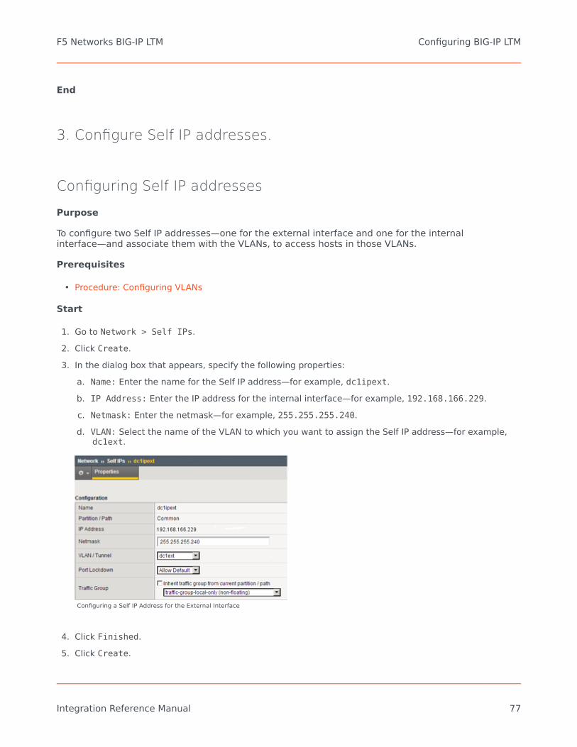
End
3. Configure Self IP addresses.
Configuring Self IP addresses
Purpose
To configure two Self IP addresses—one for the external interface and one for the internalinterface—and associate them with the VLANs, to access hosts in those VLANs.
Prerequisites
• Procedure: Configuring VLANs
Start
1. Go to Network > Self IPs.2. Click Create.3. In the dialog box that appears, specify the following properties:
a. Name: Enter the name for the Self IP address—for example, dc1ipext.b. IP Address: Enter the IP address for the internal interface—for example, 192.168.166.229.c. Netmask: Enter the netmask—for example, 255.255.255.240.d. VLAN: Select the name of the VLAN to which you want to assign the Self IP address—for example,
dc1ext.
Configuring a Self IP Address for the External Interface
4. Click Finished.5. Click Create.
F5 Networks BIG-IP LTM Configuring BIG-IP LTM
Integration Reference Manual 77

6. In the dialog box that appears, specify the following properties:a. Name: Enter the name for the Self IP address—for example, dc2ipsip.b. IP Address: Enter the IP address for the internal interface—for example, 192.168.167.96.c. Netmask: Enter the netmask—for example, 255.255.255.128.d. VLAN: Select the name of the VLAN to which you want to assign the self IP address—for example,
dc2sip.
Configuring a Self IP Address for the Internal Interface
7. Click Finished.
End
4. Configure the Default IP route.
Configuring the Default IP route
Purpose
To configure the default IP route.
Prerequisites
• Procedure: Configuring Self IP addresses
Start
1. Go to Network > Routes.2. Click Add.3. In the dialog box that appears, specify the following properties:
F5 Networks BIG-IP LTM Configuring BIG-IP LTM
Integration Reference Manual 78

a. Name: Enter Default.b. Resource: Select Use Gateway.c. Gateway Address: Enter the IP address for this default IP route—for example, 192.168.166.225.
Configuring Default IP Route
4. Click Finished.
End
5. Configure SIP Server nodes.
Configuring SIP Server nodes
Purpose
To configure two SIP Server nodes, primary and backup.
Prerequisites
• Procedure: Configuring the Default IP route
Start
1. Go to Local Traffic > Nodes.2. Click Create.3. In the dialog box that appears, specify the following properties:
a. Name: Enter the node name—for example, nodeHa01Primary.b. Address: Enter the IP address for the primary SIP Server node—for example, 192.168.167.125.c. Health Monitors: Select Node Specific.
F5 Networks BIG-IP LTM Configuring BIG-IP LTM
Integration Reference Manual 79

d. Select Monitors > Active: Select icmp.
Configuring a Primary SIP Server Node
4. Click Finished.5. Click Create.6. In the dialog box that appears, specify the following properties:
a. Name: Enter the node name—for example, nodeHa01Backup.b. Address: Enter the IP address for the backup SIP Server node—for example, 192.168.167.126.c. Health Monitors: Select Node Specific.d. Select Monitors > Active: Select icmp.
F5 Networks BIG-IP LTM Configuring BIG-IP LTM
Integration Reference Manual 80

Configuring a Backup SIP Server Node
7. Click Finished.
6. Configure a health monitor.
Configuring a health monitor
In general, the BIG-IP LTM uses health monitors to determine whether a server to which messagescan be routed is operational (active). Servers that are flagged as not operational (inactive) will causethe BIG-IP LTM to route messages to another server if one is present in the same server pool.However, primary and backup SIP Servers must be configured as the only members of the sameserver pool--one member active (primary) and one member inactive (backup).
In this procedure, the BIG-IP LTM is configured to use the health monitor of SIP type in UDP mode.This means that the OPTIONS request method will be sent to both primary and backup SIP Servers.Any response to OPTIONS is configured as Accepted Status Code.
SIP Server always starts in backup mode, establishes a permanent connection with the GenesysManagement Layer, and changes its role to primary only if a trigger from the Management Layer isreceived. Such trigger is only generated if no other primary SIP Server is currently running. Afterswitching to primary mode, SIP Server responds to UDP packets received on the SIP port specified bythe sip-port configuration option. Therefore, after receiving the OPTIONS request from the BIG-IP
F5 Networks BIG-IP LTM Configuring BIG-IP LTM
Integration Reference Manual 81

LTM, SIP Server responds to the health check, and the BIG-IP LTM marks SIP Server as active.
When running in backup mode, SIP Server ignores UDP messages. Since the BIG-IP LTM does notreceive any response to the OPTIONS request, it marks the backup SIP Server as inactive. If SIP Serverdoes not respond because of network latency or other reasons, the BIG-IP LTM will mark SIP Server asinactive, and continue sending ping messages periodically.
The Interval setting defines how often pool members (primary and backup) are checked forpresence. The Timeout setting defines the waiting time before an unresponsive member of the poolis marked as inactive. Regardless of the member's status (or SIP Server status), the BIG-IP LTM willalways check servers for presence. When an inactive member responds to the health check, it ismarked as active. In this configuration, the Interval parameter is set to 1 second and Timeout to 4seconds in order to minimize a possible delay that might result from a switchover.
Start
1. Go to Local Traffic > Monitors.2. Click Create.3. In the dialog box that appears, specify the following properties:
a. Name: Enter the name for this health monitor—for example, monSipUdp.b. Type: Select SIP.c. Configuration: Select Basic.d. Interval: Enter 1 (seconds).e. Timeout: Enter 4 (seconds).f. Mode: Select UDP.
g. Additional Accepted Status Codes: Select Any.
Configuring a Health Monitor
F5 Networks BIG-IP LTM Configuring BIG-IP LTM
Integration Reference Manual 82

4. Click Finished.
End
7. Configure a server pool.
Configuring a server pool
Purpose
To configure a server pool with which the BIG-IP LTM will communicate.
Start
1. Go to Local Traffic > Pools.2. Click Create.3. In the dialog box that appears, specify the following properties:
a. Name: Enter the name for this server pool—for example, the poolHa01.b. Health Monitors > Active: Select monSipUdp.c. Action On Service Down: Select Reselect.d. Priority Group Activation: Select Disabled.
F5 Networks BIG-IP LTM Configuring BIG-IP LTM
Integration Reference Manual 83

Configuring a Server Pool
4. Click Finished.
End
8. Add server pool members.
Adding server pool members
Purpose
To add primary and backup SIP Servers to the server pool. Note that they must be the only membersof this server pool.
Start
F5 Networks BIG-IP LTM Configuring BIG-IP LTM
Integration Reference Manual 84

1. Go to Local Traffic > Pools > poolHa01 > Members.2. Click Add.3. In the dialog box that appears, specify the following properties:
a. Node Name: Select the primary server node you created in Configuring SIP Server nodes. In ourexample, it would be nodeHa01Primary.
b. Address: Specify the IP address of the primary server node. In our example, it would be192.168.167.125.
c. Service Port: Enter 5060.
Adding the Primary SIP Server to the Server Pool
4. Click Finished.5. Click Add.6. In the dialog box that appears, specify the following properties:
a. Node Name: Select the backup server node you created in the Configuring SIP Server nodes. In ourexample, it would be nodeHa01Backup.
b. Address: Specify the IP address of the backup server node. In our example, it would be192.168.167.126.
c. Service Port: Enter 5060.
F5 Networks BIG-IP LTM Configuring BIG-IP LTM
Integration Reference Manual 85

Adding the Backup SIP Server to the Server Pool
7. Click Finished.8. Set the Load Balancing Method to Round Robin.9. Go to Local Traffic > Pools. The status of the nodeHa01Primary server pool member displays as
available (green).
The Server Pool of Two Members
End
9. Configure data groups.
Configuring data groups
Purpose
To configure data groups that will be used by the iRule. One data group (dataGroupSnatHa01)
F5 Networks BIG-IP LTM Configuring BIG-IP LTM
Integration Reference Manual 86
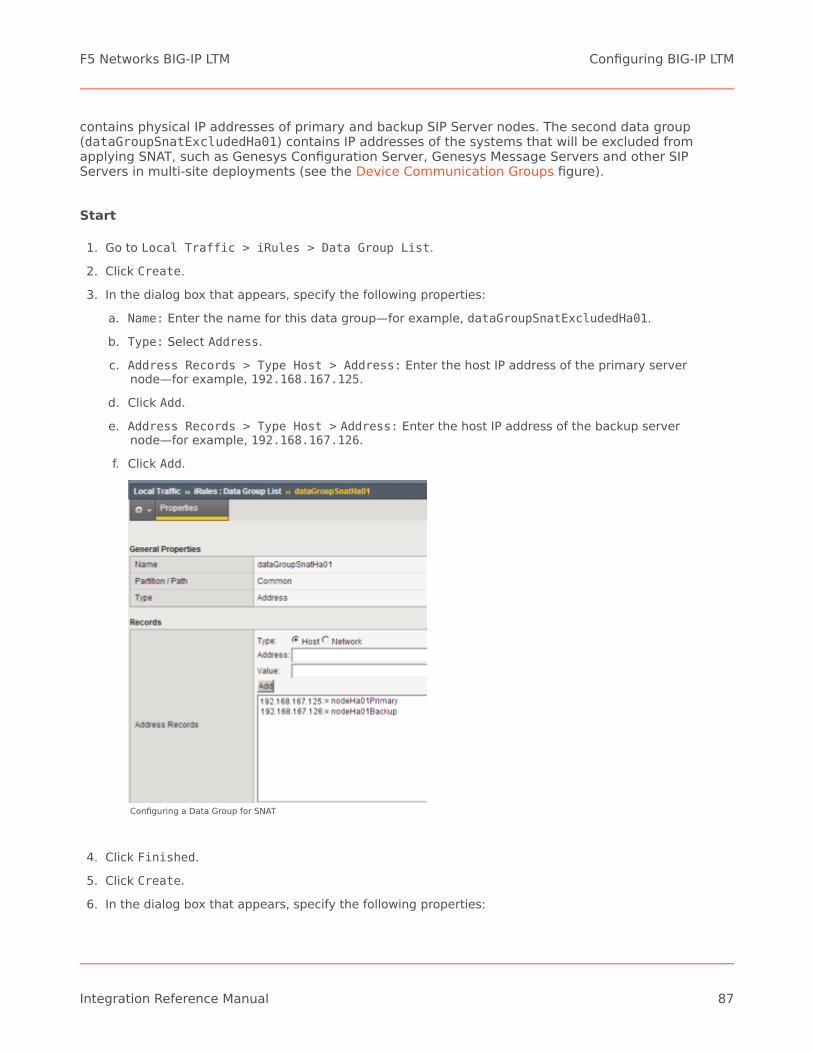
contains physical IP addresses of primary and backup SIP Server nodes. The second data group(dataGroupSnatExcludedHa01) contains IP addresses of the systems that will be excluded fromapplying SNAT, such as Genesys Configuration Server, Genesys Message Servers and other SIPServers in multi-site deployments (see the Device Communication Groups figure).
Start
1. Go to Local Traffic > iRules > Data Group List.2. Click Create.3. In the dialog box that appears, specify the following properties:
a. Name: Enter the name for this data group—for example, dataGroupSnatExcludedHa01.b. Type: Select Address.c. Address Records > Type Host > Address: Enter the host IP address of the primary server
node—for example, 192.168.167.125.d. Click Add.e. Address Records > Type Host > Address: Enter the host IP address of the backup server
node—for example, 192.168.167.126.f. Click Add.
Configuring a Data Group for SNAT
4. Click Finished.5. Click Create.6. In the dialog box that appears, specify the following properties:
F5 Networks BIG-IP LTM Configuring BIG-IP LTM
Integration Reference Manual 87

a. Name: Enter the name for this data group—for example, dataGroupSnatExcluded01.b. Type: Select Address.c. Address Records > Type Host > Address: Enter the host IP address of Genesys Configuration
Server—for example, 172.21.83.193.d. Click Add.
Configuring a Data Group for SNAT Exclusions
7. Click Finished.
End
10. Configure a SNAT pool.
Configuring a SNAT pool
Purpose
To configure a SNAT pool that specifies the Virtual IP address to be used as a source IP address forany packet that originates from the primary or backup SIP Server to which SNAT is applied (with theexception of the devices specified in the dataGroupSnatExcluded01 data group). SNAT is themapping of one or more original IP addresses to a translation address.
Start
1. Go to Local Traffic > SNATs.
F5 Networks BIG-IP LTM Configuring BIG-IP LTM
Integration Reference Manual 88

2. Click Create.3. In the dialog box that appears, specify the following properties:
a. Name: Enter the name for this SNAT pool—for example, snatPoolVipHa01.b. Configuration > Members List > IP Address: Enter the IP address to be used as a source IP
address—for example, 192.168.166.238.c. Click Add.
Configuring a SNAT Pool
4. Click Finished.
End
11. Configure an iRule.
Configuring an iRule
Purpose
To configure an iRule that is used to perform SNAT to the Virtual IP address to any packets thatoriginate from the primary or backup SIP Server (with the exception of the packets addressed toConfiguration Server and the Genesys T-Library Clients group). This iRule will then be associated witha Virtual Server for the outbound traffic, vsWildCardOutbound. In this deployment architecture, theHA synchronization traffic between primary and backup SIP Servers does not pass through the BIG-IPLTM, that is why it is excluded from applying SNAT.
Start
1. Go to Local Traffic > iRules.
F5 Networks BIG-IP LTM Configuring BIG-IP LTM
Integration Reference Manual 89

2. Click Create.3. In the dialog box that appears, specify the following properties:
a. Name: Enter the name for this iRule—for example, iRuleSnatOutboundHa01.b. Definition: Enter the following text:
#======================================================## Apply SNAT as specified in snatPoolVipHa01 for all# packets originated from dataGroupSnatHa01 members.# Exclude packets addressed to members of# dataGroupSnatExcludedHa01.#======================================================#when CLIENT_ACCEPTED {
if { [class match [IP::remote_addr] equals dataGroupSnatHa01] }{
if { [class match [IP::local_addr] equals dataGroupSnatExcludedHa01] }{}else{
snatpool snatPoolVipHa01}
}}
4. Click Finished.
End
12. Configure a Virtual Server.
Configuring a Virtual Server
Complete the following steps:
[+] Configuring a Virtual Server for outbound traffic
Purpose
To configure a Virtual Server to be used for outbound traffic. It is associated with a VLAN that isconfigured for the internal interface (see Procedure: Configuring VLANs) and it has iRule assigned toResources, which applies SNAT to all packets (except for packets addressed to Configuration Server).
Prerequisites
• Procedure: Configuring an iRule
Start
1. Go to Local Traffic > Virtual Servers.
F5 Networks BIG-IP LTM Configuring BIG-IP LTM
Integration Reference Manual 90

2. Click Create.3. In the dialog box that appears, specify the following properties:
a. Name: Enter the name for this Virtual Server—for example, vsWildCardOutbound.b. Type: Select Forwarding (IP).c. Destination > Type: Select Network.d. Destination > Address: Enter 0.0.0.0.e. Destination > Mask: Enter 0.0.0.0.f. Service Port: Enter * All Ports.
g. Configuration: Select Advanced.h. Protocol: Select * All Protocols.i. VLAN Traffic: Select Enabled on...j. VLAN List Selected: Select dc2sip.k. SNAT Pool: Select None.l. Source Port: Select Preserve.
F5 Networks BIG-IP LTM Configuring BIG-IP LTM
Integration Reference Manual 91

Configuring a Wildcard Virtual Server for Outbound Traffic
4. Click Finished.5. Go to Local Traffic > Virtual Server List > vsWildcardOutbound > Resources.6. Add iRule as follows:
Resources > iRule Enabled > iRuleSnatOutboundHa01
End
[+] Configuring a Virtual Server for inbound traffic
Purpose
F5 Networks BIG-IP LTM Configuring BIG-IP LTM
Integration Reference Manual 92

To configure a Virtual Server for inbound traffic. In Layer 3/Routing configuration mode, the BIG-IP LTMpasses through only those packets that have a destination matching a virtual server. Having theVirtual Server for inbound traffic allows packets with a destination that matches the physical IPaddress of the primary or backup SIP Server to pass through.
Start
1. Go to Local Traffic > Virtual Servers.2. Click Create.3. In the dialog box that appears, specify the following properties:
a. Name: Enter the name for this Virtual Server—for example, vsWildCardInbound.b. Type: Select Forwarding (IP).c. Destination > Type: Select Network.d. Destination > Address: Enter 0.0.0.0.e. Destination > Mask: Enter 0.0.0.0.f. Service Port: Enter * All Ports.
g. Configuration: Select Advanced.h. Protocol: Select * All Protocols.i. VLAN Traffic: Select Enabled on....j. VLAN List Selected: Select dc1ext.
F5 Networks BIG-IP LTM Configuring BIG-IP LTM
Integration Reference Manual 93

Configuring a Wildcard Virtual Server for Inbound Traffic
4. Click Finished.
End
[+] Configuring Virtual Servers for UDP and TCP SIP communications
Purpose
To configure two virtual servers to handle traffic directed to a Virtual IP address: one virtual server forSIP communications using the UDP as a transport protocol and one virtual server for SIPcommunications using the TCP as a transport protocol. The Virtual IP address is used by SIP clients tocontact SIP Server. In other words, the Virtual IP address hides two physical IP addresses (used by theprimary and backup servers) and presents the SIP Server HA pair as a single entity for all SIP-basedcommunications.
F5 Networks BIG-IP LTM Configuring BIG-IP LTM
Integration Reference Manual 94

Start
1. Go to Local Traffic > Virtual Servers.2. Click Create.3. In the dialog box that appears, specify the following properties:
a. Name: Enter the name for this Virtual Server—for example, vsVipUdpHa01.b. Destination > Type: Select Host.c. Destination > Address: Enter the IP address for this Virtual Server—for example,
192.168.166.238.d. Service Port: Enter 5060 and select Other.e. State: Select Enabled.f. Configuration: Select Advanced.
g. Type: Select Standard.h. Protocol: Select UDP.i. SMTP Profile: Select None.j. SIP Profile: Select sip.k. VLAN Traffic: Select Enabled on...l. VLAN List Selected: Select dc1ext.
F5 Networks BIG-IP LTM Configuring BIG-IP LTM
Integration Reference Manual 95

Configuring a Virtual Server for UDP-Based Communications
F5 Networks BIG-IP LTM Configuring BIG-IP LTM
Integration Reference Manual 96

4. Click Finished.5. Select Resources > Load Balancing > Default Pool: Select poolHa01.6. Click Update.7. Go to Local Traffic > Virtual Servers.8. Click Create.9. In the dialog box that appears, specify the following properties:
a. Name: Enter the name for this Virtual Server—for example, vsVipTcpHa01.b. Destination > Type: Select Host.c. Destination > Address: Enter the IP address for this Virtual Server—for example,
192.168.166.238.d. Service Port: Enter 5060 and select Other.e. State: Select Enabled.f. Configuration: Select Basic.
g. Type: Select Standard.h. Protocol: Select TCP.i. SMTP Profile: Select None.j. SIP Profile: Select sip.k. VLAN Traffic: Select Enabled on...l. VLAN List Selected: Select dc1ext.
F5 Networks BIG-IP LTM Configuring BIG-IP LTM
Integration Reference Manual 97

Creating a Virtual Server for TCP-Based Communications
10. Click Finished.11. Select Resources > Load Balancing > Default Pool: Select poolHa01.12. Click Update.
End
Note: SNAT pool must not be activated as the configuration element of Virtual Server. SNAT must notbe applied to SIP messages sent by clients to SIP Server. Enabling SNAT for these messages results ina broken call flow, as in some circumstances the SNAT is not aligned with SIP Protocol.
<verttabber>
F5 Networks BIG-IP LTM Configuring BIG-IP LTM
Integration Reference Manual 98

Configuring TLSSecure data transfer using TLS is now supported between SIP Server and Active-Active ResourceManagers in a deployment where SIP Server high-availability is configured using the F5 Networks BIG-IP LTM. TLS is also supported between SIP Server and all SIP devices in this deployment, includingSBCs, Media Gateways, and SIP phones. BIG-IP LTM is not a TLS peer as are other elements in theenvironment; there is no TLS negotiation between BIG-IP LTM and other components.
Integration Solution AssumptionsThe integration solution described in this section makes the following assumptions:
• BIG-IP LTM is deployed as a single instance• TLS transport is used for SIP signaling• SIP Server performs load balancing between an Active-Active Resource Manager pair
See Deployment Architecture Example.
Deploying the TLS Solution
To support TLS data transfer in a SIP Server deployment with an Active-Active RM pair and a BIG-IPLTM used for the SIP Server HA, complete the following procedures:
1. Configure BIG-IP LTM for TLS.2. Provision SSL certificates for workstations hosting SIP Servers, RM, and MCP applications. Refer to the
''Genesys 8.1 Security Deployment Guide''.3. Configure SIP Server to use TLS data transfer. Refer to the Transport Layer Security for SIP Traffic
section in the Framework 8.1 SIP Server Deployment Guide.4. Configure Resource Managers in an Active-Active high-availability cluster. Refer to the Genesys Voice
Platform Integration section in the ''Framework 8.1 SIP Server Deployment Guide''.
To configure TLS data transfer between Genesys Media Server components, refer to the ''GenesysMedia Server 8.1 Deployment Guide''.
Configuring BIG-IP LTM for TLS
1. Complete general configuration procedures.
Before starting the TLS-specific configuration of BIG-IP LTM, complete the configuration procedures.
F5 Networks BIG-IP LTM Configuring TLS
Integration Reference Manual 99

2. Configure a health monitor.
To configure a health monitor:
1. Go to Local Traffic > Monitors.2. Click Create.3. In the dialog box that appears, specify the following properties:
• Name: Enter the name for this health monitor—for example, monSipTls.• Type: Select TCP.• Parent Monitor: Select TCP.• Configuration: Select Basic.• Interval: Enter 1 (seconds).
4. Click Finished.
3. Configure a server pool.
To configure a server pool:
1. Go to Local Traffic > Pools.2. Click Create.3. In the dialog box that appears, specify the following properties:
• Name: Enter the name for this server pool—for example, the poolHa01tls.• Configuration: Select Advanced.• Health Monitors > Active: Select monSipTls.• Action On Service Down: Select Reselect.• Slow Ramp Time: Enter0 (seconds).
4. Click Finished.
4. Add server pool members.
To add server pool members:
1. Go to Local Traffic > Pools > poolHa01tls > Members.2. Click Add.
F5 Networks BIG-IP LTM Configuring TLS
Integration Reference Manual 100

3. In the dialog box that appears, specify the following properties:• Node Name: Select the primary server node. In our example, it would be nodeHa01Primary.• Address: Specify the IP address of the primary server node. In our example, it would be
192.168.167.125.• Service Port: Enter 5061.
4. Click Finished.5. Click Add.6. In the dialog box that appears, specify the following properties:
• Node Name: Select the backup server node. In our example, it would be nodeHa01Backup.• Address: Specify the IP address of the backup server node. In our example, it would be
192.168.167.126.• Service Port: Enter 5061.
7. Click Finished.8. Set the Load Balancing Method to Round Robin.
5. Configure a Virtual Server.
To configure a Virtual Server:
1. Go to Local Traffic > Virtual Servers.2. Click Create.3. In the dialog box that appears, specify the following properties:
• Name: Enter the name for this Virtual Server—for example, vsVipTlsHa01.• Destination > Type: Select Host.• Destination > Address: Enter the IP address for this Virtual Server—for example,
192.168.166.238.• Service Port: Enter 5061 (Other).• State: Select Enabled.• Configuration: Select Basic.• Type: Select Standard.• Protocol: Select TCP.• VLAN and Tunnel Traffic: Select Enabled on...• VLANs and Tunnels Selected: Select dc1ext.
4. Click Finished.
F5 Networks BIG-IP LTM Configuring TLS
Integration Reference Manual 101

5. Select Local Traffic > Virtual Server List > vsVipTlsHa01 > Resources.6. Add Default Pool: poolHa01tls7. Click Update.
6. Disable Virtual Servers for UDP and TCP.
At this point, the BIG-IP LTM is configured for handling communications over different protocols: UDP,TCP, and TLS. If TLS is mandatory for security reasons, Genesys strongly recommends disablingvirtual servers for insecure protocols, such as UDP and TCP.
To disable Virtual Servers for UDP and TCP:
1. Go to Local Traffic > Virtual Servers.2. Select check boxes of the following virtual servers: vsVipUdpHa01 and vsVipTcpHa01.3. Click Disable.
This completes configuring BIG-IP LTM.
F5 Networks BIG-IP LTM Configuring TLS
Integration Reference Manual 102

Deployment Architecture ExampleThe figure below depicts the architecture of a sample deployment of primary and backup SIP Servers,Active-Active Resource Manager pair, and the BIG-IP LTM, in which:
• BIG-IP LTM provides a single Virtual IP address for SIP phones and Media Server.• The pair of SIP Servers configured in Hot-Standby mode is located behind BIG-IP LTM and the actual IP
addresses of the primary and backup SIP Servers are not exposed to phones or Media Servercomponents.
• All SIP entities in the environment—phones, SIP Servers, Resource Managers, MCPs—can use TLS for SIPsignaling if configured.
F5 Networks BIG-IP LTM Deployment Architecture Example
Integration Reference Manual 103
RedSky E911 ManagerStarting with release 8.1.102.81, Genesys SIP Server can operate with the RedSky E911 Managersystem, the provider of emergency (911) calls in the VoIP environment. Workspace SIP Endpointversion 8.5.113.02 or later must be used for this integration.
SIP Server was tested with the following RedSky components:
• RedSky E911 Manager version 6.7.0• RedSky Emergency Gateway version 6.5-122
All communication transport protocols are supported: UDP, TCP, or TLS.
For this integration, you configure:
• Genesys SIP Server, DN configuration objects• RedSky components
Genesys Configuration
Configure the following DN configuration objects under the SIP Server switch:
• The DN object of type Trunk for the RedSky E911 Manager must have the following options configuredin the TServer section:• contact—Set to the RedSky E911 Manager URI. The URI format is described in the contact option
description in the Framework 8.1 SIP Server Deployment Guide.• prefix—Set to a value that matches emergency call starting digits.• contact-list—Configure this option if there is more than one instance of the Red Sky E911 Manager
in the environment.• oos-check• oos-force• emergency-device—Set to true.
• The DN object of type Trunk for the RedSky Emergency Gateway must have the following optionsconfigured in the TServer section:• contact—Set to the RedSky Emergency Gateway URI.• prefix—Set to a value different from the Trunk DN pointing to Red Sky Server.• contact-list—Configure this option if there is more than one instance of the Red Sky Server in the
environment.• oos-check
RedSky E911 Manager Deployment Architecture Example
Integration Reference Manual 104

• oos-force• emergency-device—Set to true.
The SIP Server Application must contain the following configuration options in the TServer section:
• subscription-event-allowed—Set this option to reg or * (asterisk).• subscription-max-body-size—Define the maximum size of the NOTIFY XML body (in bytes) within the
SUBSCRIBE dialog. The default value is 14336. The range of valid values is 0–500000. If the option is setto 0 (zero), the message body can be any size. The zero value can be used for TCP transport but is notrecommended for UDP. For bulk notification, SIP Server sends more than one NOTIFY, so adjust the sizeaccordingly.
• sip-elin-timeout—Define the time interval, in seconds, for SIP Server to keep in memory theassociation between a 911 caller and the Emergency Location Identification Number (ELIN) assigned tothe caller. The default value is 1200. The range of valid values is 0–3600. If a call arrives at that ELINbefore the timeout expires, the call is sent to the associated 911 caller DN. If within this time intervalthere are several emergency calls with the same ELIN, SIP Server directs the callback to the latestcaller.
RedSky Configuration
On the RedSky side, configure the following components:
• RedSky Emergency Gateway• RedSky E911 Manager—Add "Genesys" as a call server using the Call Servers module. Refer to RedSky
documentation for details.
RedSky E911 Manager subscribes to SIP Server for endpoint state notifications. It discovers a physicallocation of a DN based on its IP address and, if possible, its MAC address, then assigns theEmergency Location Identification Number (ELIN) to each endpoint. When E911 Manager receives anemergency call initial INVITE message, it redirects it providing the ELIN of the calling endpoint. TheRedSky Emergency Gateway receives the redirected INVITE and sends the voice call to the public-safety answering point (PSAP) agency.
RedSky E911 Manager Deployment Architecture Example
Integration Reference Manual 105

Known Limitations
For the SIP Server and RedSky solution to work correctly, the following conditions must be met:
• SIP Server is running in the non-cloud environment (no SBC to mask endpoint IP addresses with its ownaddress).
• Agent DNs are self-registered endpoints.• The MAC address is provided to RedSky only for deployment with Genesys SDK-based endpoints running
on dedicated hardware hosts (not virtual machines).
RedSky E911 Manager Deployment Architecture Example
Integration Reference Manual 106