intel 8251 benchmark -- -- source: intel data book -- -- vhdl
TRANSCRIPT

------------------------------------------------------------------------------------ Intel 8251 Benchmark---- Source: Intel Data Book---- VHDL Benchmark author Indraneel Ghosh-- University Of California, Irvine, CA 92717---- Developed on April 7, 92----------------------------------------------------------------------------------
------------------------------------- The 8251 Chip----------------------------------
(1) Introduction *****************
The Intel 8251 Universal Synchronous/Asynchronous Receiver/Transmitter (USART), designed for data communication with Intel's microprocessor families. It is used as a peripheral device and is programmed by the CPU to operate using many serial data transmission techniques.
The USART accepts data characters from the CPU in parallel format and then converts them into a continuous serial data stream. It accepts serial data streams and converts them into parallel data characters for the CPU. The USART will signal the CPU whenever it can accept a new character for transmission or whenever it has received a character for the CPU. The CPU can read the status of the USART at any time. The status includes data transmission errors and control signals SYNDET/BD, TxEMPTY, TxRDY, RxRDY.
###########################################################################
(2) Ports **********
RESET ( 1 BIT, INPUT PORT ) : ----------------------------- This is the master reset for the 8251 chip.
D_7 to D_0 ( 8 PINS, 1 BIT each, INOUT PORTS) : ----------------------------------------------- These are the bi-directional data bus pins (8 bits) used for transferring data/control/status words transfer the USART and the CPU. These are usually connected to the CPU's data-bus, although the CPU always remains in control of the bus and initiates all transfers.
CS_BAR ( 1 BIT, INPUT PORT ) : ------------------------------ This is the Chip-Select line. A low on this line enables data communication between the CPU and the USART.
RD_BAR ( 1 BIT, INPUT PORT ) : ------------------------------ This is the read line. A low on this line causes the USART to place the status word or the ( received ) data word on the data bus pins ("D_7" to "D_0").
WR_BAR ( 1 BIT, INPUT PORT ) : ------------------------------
This is the write line. A low on this line causes the USART to accept the data on the data bus pins ( "D_7" to "D_0") as either a control word or as a data character (for transmission).
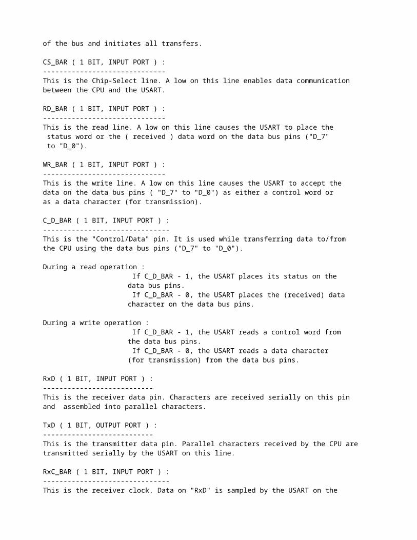
C_D_BAR ( 1 BIT, INPUT PORT ) : ------------------------------- This is the "Control/Data" pin. It is used while transferring data to/from the CPU using the data bus pins ("D_7" to "D_0").
During a read operation : If C_D_BAR - 1, the USART places its status on the
data bus pins. If C_D_BAR - 0, the USART places the (received) data
character on the data bus pins. During a write operation :
If C_D_BAR - 1, the USART reads a control word from the data bus pins.
If C_D_BAR - 0, the USART reads a data character (for transmission) from the data bus pins.
RxD ( 1 BIT, INPUT PORT ) : --------------------------- This is the receiver data pin. Characters are received serially on this pin and assembled into parallel characters.
TxD ( 1 BIT, OUTPUT PORT ) : --------------------------- This is the transmitter data pin. Parallel characters received by the CPU are transmitted serially by the USART on this line.
RxC_BAR ( 1 BIT, INPUT PORT ) : ------------------------------- This is the receiver clock. Data on "RxD" is sampled by the USART on the rising edge of "RxC_BAR".
TxC_BAR ( 1 BIT, INPUT PORT ) : ------------------------------- This is the transmitter clock. Data is shifted out serially on "TxD" by the USART, on the falling edge of "TxC_BAR".
CLK ( 1 BIT, INPUT PORT ) : --------------------------- This clock is used for internal device timing. It needs to be faster than "TxC_BAR" and "RxC_BAR".
TxEMPTY ( 1 BIT, OUTPUT PORT ) : -------------------------------- A high on this line indicates that the serial buffer in the transmitter is empty. This line goes low only while a data character is being transmitted by the USART. It goes high as soon as the USART completes transmitting a character and a new one has not been loaded in time.
TxRDY ( 1 BIT, OUTPUT PORT ) : ------------------------------ This pin signals the CPU that the USART is ready to accept a new data character for transmission. "TxRDY" is reset when the USART receives a data character from the CPU.
RxRDY ( 1 BIT, OUTPUT PORT ) : ------------------------------ This pin signals the CPU that the USART has received a character on its serial input "RxD" and is ready to transfer it to the CPU. "RxRDY" is reset when the character is read by the CPU.

SYNDET_BD (1 BIT, INOUT PORT ) : -------------------------------- In the Synchronous mode, this line can be in two ways (while receiving characters). In the "Internal-Synchronization" mode, this line is used as an output which goes high when the programmed "SYNC-characters" are detected on the "RxD" line. In the "External-Synchronization" mode, this line is used as an input and the USART starts assembling data characters at the next clock ("RxC_BAR") edge after a rising edge on this line.
In the Asynchronous mode, this line is used as a "Break-Detect" output which goes high if the "RxD" line has stayed low for two consecutive character lengths (including start, stop and parity bits).
RTS_BAR (1 BIT, OUTPUT PORT) : ------------------------------ This "Request-To_Send" is a general purpose output signal that can be asserted by a "command word" from the CPU. It may be used to request that the modem prepare itself to transmit.
CTS_BAR (1 BIT, INPUT PORT) : ------------------------------ This "Clear-To-Send" is an input signal that can be read by the CPU as part of the "status-word". A low on this line enables the USART to transmit data. A low on "CTS_BAR" is normally generated as a response to an assertion on "RTS_BAR".
DTR_BAR (1 BIT, OUTPUT PORT) : ------------------------------ This "Data-Terminal-Ready" is a general purpose output signal that can be asserted by a "command word" from the CPU.
DSR_BAR (1 BIT, INPUT PORT) : ------------------------------ This "Data-Set-Ready" is a general purpose input signal that can be read by the CPU as part of the "status-word".
###########################################################################
(3) General Operation **********************
(3.1) Programming the 8251 ===========================
The complete functional definition of the 8251 is programmed by the system's software. A set of control words must be sent out by the CPU to initialize the 8251 to support the desired communication format. These words must immediately follow a reset (internal/external).
(3.1.1) The Mode word ----------------------
Immediately after a reset, the CPU has to send the 8-bit "mode" word. The 8251 can be used for either synchronous/asynchronous data communication. To understand how the mode instruction works, its best to view the device as two separate components, one synchronous and the other asynchronous.
"Synchronous" mode word - - - - - - - - - - - - _________________ | Bit 0 | Bit 1 | The two least significant bits must be both 0 in |-------|-------| Synchronous mode.

| 0 | 0 | |_______|_______|
Character length : (bits per character) ________________________________ | Bit 3 | Bit 2 || | |-------|-------||-------------| | 0 | 0 || 5 bits | |_______|_______||_____________| | | || | | 0 | 1 || 6 bits | |_______|_______||_____________| | | || | | 1 | 0 || 7 bits | |_______|_______||_____________| | | || | | 1 | 1 || 8 bits | |_______|_______||_____________|
Parity : ________________________________ | Bit 5 | Bit 4 || | |-------|-------||-------------| | 0 | 0 || No parity | |_______|_______||_____________| | | || | Bit 4 -- Parity Enable | 0 | 1 || Odd parity | |_______|_______||_____________| Bit 5 -- Even Parity | | || | | 1 | 0 || No parity | |_______|_______||_____________| | | || | | 1 | 1 || Even parity | |_______|_______||_____________|
Synchronization scheme : __________________________________________________________________ | Bit 7 | Bit 6 || | |-------|-------||-----------------------------------------------| | 0 | 0 || Internal sync detect, Double Sync character | |_______|_______||_______________________________________________| | | || | | 0 | 1 || External sync detect (from SYNDET_BD input) | |_______|_______||_______________________________________________| | | || | | 1 | 0 || Internal sync detect, Single Sync character | |_______|_______||_______________________________________________| | | || | | 1 | 1 || External sync detect (from SYNDET_BD input) | |_______|_______||_______________________________________________|
Bit 6 -- External Synchronization
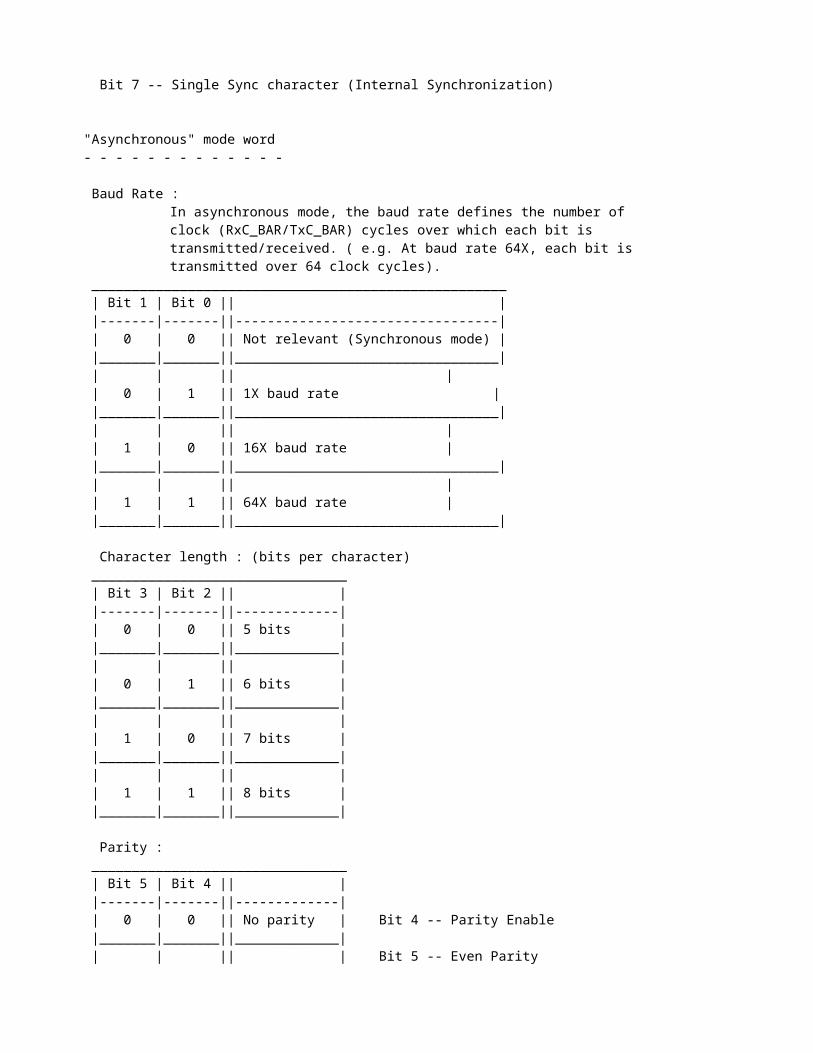
Bit 7 -- Single Sync character (Internal Synchronization)
"Asynchronous" mode word - - - - - - - - - - - - -
Baud Rate :In asynchronous mode, the baud rate defines the number of clock (RxC_BAR/TxC_BAR) cycles over which each bit is transmitted/received. ( e.g. At baud rate 64X, each bit istransmitted over 64 clock cycles).

____________________________________________________ | Bit 1 | Bit 0 || | |-------|-------||---------------------------------| | 0 | 0 || Not relevant (Synchronous mode) | |_______|_______||_________________________________| | | || | | 0 | 1 || 1X baud rate | |_______|_______||_________________________________| | | || | | 1 | 0 || 16X baud rate | |_______|_______||_________________________________| | | || | | 1 | 1 || 64X baud rate | |_______|_______||_________________________________|
Character length : (bits per character) ________________________________ | Bit 3 | Bit 2 || | |-------|-------||-------------| | 0 | 0 || 5 bits | |_______|_______||_____________| | | || | | 0 | 1 || 6 bits | |_______|_______||_____________| | | || | | 1 | 0 || 7 bits | |_______|_______||_____________| | | || | | 1 | 1 || 8 bits | |_______|_______||_____________|
Parity : ________________________________ | Bit 5 | Bit 4 || | |-------|-------||-------------| | 0 | 0 || No parity | Bit 4 -- Parity Enable |_______|_______||_____________| | | || | Bit 5 -- Even Parity | 0 | 1 || Odd parity | |_______|_______||_____________| | | || | | 1 | 0 || No parity | |_______|_______||_____________| | | || | | 1 | 1 || Even parity | |_______|_______||_____________|
No of Stop Bits : __________________________________ | Bit 7 | Bit 6 || | |-------|-------||---------------| | 0 | 0 || Invalid | |_______|_______||_______________| | | || | | 0 | 1 || 1 stop bit | |_______|_______||_______________| | | || | | 1 | 0 || 1.5 stop bits | |_______|_______||_______________| | | || | | 1 | 1 || 2 stop bits | |_______|_______||_______________|
~~~~~~~~~~~~~~~~~~~~~~~~~~~~~~~~~~~~~~~~~~~~~~~~~~~~~~~~~~~~~~~~~~~~~~~~~~~~~~
(3.1.2) The Command word and SYNC characters ---------------------------------------------
In the "Internal Synchronization" mode, the control words (from the CPU) that follow the mode word, must be SYNC characters. In Single-Sync mode, only one SYNC character (SYNC1) is loaded. In Double-Sync mode, two consecutive SYNC characters (SYNC1 followed by SYNC2) must be loaded. The SYNC character(s) have the same number of bits as the data characters (as programmed in the mode word).
The SYNC characters (if present, i.e. in "Internal Synchronization" mode) are followed by the command word from the CPU. Data words (for transmission) can follow that.
Actually, the command word can be written by the CPU at any time in the data block during the operation of the USART. To write a new Mode word, the master reset in the Command instruction can be set to initiate an "Internal Reset".
Command Word - - - - - - - Bit 0 : Transmitter Enable
Bit 1 : DTR (Data Terminal Ready) -- Controls DTR_BAR output( if this is high, DTR_BAR is low)
Bit 2 : Receiver enable
Bit 3 : Send Break -- Assertion of this forces "TxD" pin low
Bit 4 : Error Reset -- Reset all error flags (parity error, framing error overrun error) in the status word
Bit 5 : RTS (Request To Send) -- Controls RTS_BAR output ( if this is high, RTS_BAR is low)
Bit 6 : Internal Reset -- Resets the USART and makes it ready to accept a new mode word.
Bit 7 : Enter Hunt Mode -- ( used only in synchronous receive). If this is high, the USART tries to achieve synchronization by entering the "hunt mode". In "Internal Synchronization" mode, the USART starts looking for the programmed SYNC character(s) at the "RxD" input. In "External Synchronization" mode, the USART starts looking for a rising edge on the "SYNDET_BD" input. Once synchronization is achieved, the USART gets out of "hunt mode" and starts assembling characters at the next rising edge of "RxC_BAR".
~~~~~~~~~~~~~~~~~~~~~~~~~~~~~~~~~~~~~~~~~~~~~~~~~~~~~~~~~~~~~~~~~~~~~~~~~~~~~~
(3.1.3) The Status Word ------------------------
The CPU can read the "status word" from the USART at any time.
Bit 0 : TxRDY -- This signifies whether the transmitter is ready to receive a new character for transmission from the CPU. However, in order for the "TxRDY" PIN to be high, three conditions must be satisfied :

(a) TxRDY STATUS BIT must be high(b) "CTS_BAR" must be low(c) The transmitter must be enabled ( Bit 0 in the Command word must be high).
Bit 1 : RxRDY -- Same as "RxRDY" pin.
Bit 2 : TxEMPTY -- Same as "TxEMPTY" pin.
Bit 3 : Parity Error -- When parity is enabled and a parity error is detected in any received character, this bit is set.
Bit 4 : Overrun Error -- When the CPU does not read a received character before the next one becomes available, this bit is set. However, the previous character is lost.
Bit 5 : Framing Error -- Used only in asynchronous mode. When a valid stop bit (high) is not detected at the end of a received character, this bit is set.
(Note : All three error flags are reset by the "Error Reset" command bit. Also, the setting of these error flags does not inhibit the USART operation.)
Bit 6 : SYNDET_BD -- Same as "SYNDET_BD" pin.
Bit 7 : DSR (Data Set Ready) -- Controlled by "DSR_BAR" pin. (If "DSR_BAR" pin is low, his status bit is high.)
+++++++++++++++++++++++++++++++++++++++++++++++++++++++++++++++++++++++++++++
(3.2) Asynchronous Mode (Transmission) =======================================
Whenever a data character is sent by the CPU the USART automatically adds a "Start Bit" (low level) followed by the data bits (least significant bit first) and the programmed number of "Stop Bits" (high level) at the end of each character. If parity is enabled in the mode word, a "Parity Bit" (even/odd) is added before the "Stop Bit(s)". The character is then transmitted at the as a serial data stream on the "TxD" output. The serial data is shifted out on the falling edge of "TxC_BAR" at a rate equal to 1, 1/16th, or 1/64th that of "TxC_BAR", according to the Baud Rate defined in the mode word. BREAK characters (low level) can be continually sent to the "TxD" output if commanded to do so.
When no data characters have been loaded into the USART, the "TxD" output remains high (MARKING) unless a BREAK(low level) has been programmed.
+++++++++++++++++++++++++++++++++++++++++++++++++++++++++++++++++++++++++++++
(3.3) Synchronous Mode (Transmission) ======================================
The "TxD" output is continually high until the CPU writes its firsts character into the 8251 which is usually a "SYNC" character. When the CTS_BAR line goes low, the first character is serially transmitted out. A parity bit is added if parity has been enabled in the mode word. All characters are shifted out on the falling edge of "TxC_BAR".
Once transmission has been started, the data stream at the "TxD" output must continue at the "TxC_BAR" rate. If the CPU does not provide the USART with a data character before the transmitter buffer becomes empty (i.e. it finishes

transmitting the previous data character), the SYNC character(s) will be automatically inserted into the "TxD" data stream. The "TxEMPTY" line goes high to signify this.
Note : In Asynchronous/Synchronous transmission mode, any data character written into the USART, while CTS_BAR is low and the transmitter is
enabled (Bit 0 in Command Word is set), will have to be transmittedeven if the CTS_BAR line goes low subsequently.
+++++++++++++++++++++++++++++++++++++++++++++++++++++++++++++++++++++++++++++
(3.4) Asynchronous Mode (Receive) ==================================
The "RxD" line is normally high. A falling edge on this line triggers the beginning of the "Start Bit" The validity of this "Start Bit" is checked by again strobing this bit at its nominal center (only at 16X or 64X baud rate). If a low is detected again, it is a valid "Start Bit" and the bit counter will start counting. The bit counter thus locates the nominal center of the data bits and the "Parity Bit" (if it exists).
If parity error occurs, the Parity Error flag (in Status Word) is set. Data and parity bits are sampled on the "RxD" pin with the rising edge of "RxC_BAR". If a low level is detected as the "Stop Bit", the Framing Error flag (in Status Word) is set. The "Stop Bit" signifies the end of a character. The receiver requires only one "Stop Bit", regardless of the number of "Stop Bits" programmed in the Mode Word. This character is then loaded into the parallel buffer of the USART. The "RxRDY" pin is raised to signal to the CPU that a character is ready to be read. If the previously received character has'nt yet been read by the CPU, the present character replaces it in the parallel buffer and the Overrun Error flag (in Status Word) is set (the previous character is lost).
All error flags (in Status Word) can be reset by an Error Reset Instruction (in the Command Word). The occurrence of any of these errors will not affect the operation of the USART.
If the "RxD" line stays low for two full character sequences ( start bit, data bits, parity bit, stop bits), then a BREAK is detected and "SYNDET_BD" is set.
+++++++++++++++++++++++++++++++++++++++++++++++++++++++++++++++++++++++++++++
(3.4) Synchronous Mode (Receive) =================================
In this mode, character synchronization can be internally of externally achieved. If the Synchronous mode has been programmed, the ENTER HUNT command should be included in the first command instruction word written.
If "Internal Synchronization Mode" has been programmed, data on the "RxD" pin is then sampled on the rising edge of "RxC_BAR". The content of the receiver serial buffer is compared at every boundary with the first SYNC character until a match occurs. If the USART has been programmed for two SYNC characters, the subsequent received character is also compared.; when both SYNC characters have been detected, the USART ends the ENTER HUNT mode and is in character synchronization. "SYNDET_BD" is then set high and is automatically reset by a status read by the CPU. Even if parity has been programmed, the parity bit is taken in but Parity Error is not checked in ENTER HUNT mode.
If "External Synchronization Mode" has been programmed, synchronization is achieved by applying on receiving a rising edge on the "SYNDET_BD" pin.

(An ENTER HUNT command has no effect in the Asynchronous mode).
Parity Error and Overrun Error are checked for characters, as in Asynchronous Mode.
The CPU can command the USART to enter the HUNT mode (by setting Bit 7 in Command Word) if synchronization is lost. However, the USART does not automatically enter the HUNT mode when "SYNDET_BD" bit is reset on a status read. When in "Internal Synchronization Mode", but not in HUNT, Sync character detection is still functional, but only occurs at "known" word boundaries (and not at every bit boundary) and "SYNDET_BD" is set if SYNC character(s) are detected.
###########################################################################
------------------------------------- The 8251 VHDL model----------------------------------
(1) Introduction *************************
The VHDL model of the 8251 USART is divided into three major VHDL processes. The processes are called "main", "receiver" and "transmitter".
First we will look at the global signals and variables (local to a process) used in the model and their functions. Then, we will briefly study each of the three processes.
****************************************************************************
(2) Process Descriptions *************************
The VHDL model consists of three major processes ("main", "receiver" and "transmitter"). We will briefly discuss each of them.
(2.1) "main" Process =====================
The "main" process has the primary task of being an interface to the CPU. It uses the internal device clock "clk".
On getting a reset (internal/external), the main process initializes the global signals, local variables and ports.
Then, at every rising clock edge, it checks for signals from the CPU. Since a mode command (from the CPU) must immediately follow a reset, it stores the next CPU control word in the "mode" global signal. On getting the mode word, it computes the following parameters :
(a) number of bits per character(b) number of clock cycles per bit(c) number of stop-bit clock cycles (Async mode)(d) number of clock cycles through which RxD has to remain low for Break-Detect in Asynchronous receive.
These parameters are assigned to global signals and are used by the "transmitter" and "receiver" processes.
Then, the process waits for SYNC character(s), if Internal Synchronization Mode has been programmed. The SYNC character(s) are also assigned to global

signals for use by the "transmitter" and "receiver" processes. Then the process waits for a command word from the CPU. ( If Internal Synchronization Mode has not been programmed, the process waits for a command immdiately after getting a mode word, since no SYNC character(s) are expected.) The command word is assigned to a global signal "coomand" and various operations (e.g. Internal reset, error flag reset, enter HUNT MODE) are performed, depending on which bits are set in the command word.
After this initial phase, other control words sent by the CPU are interpreted as Command words.
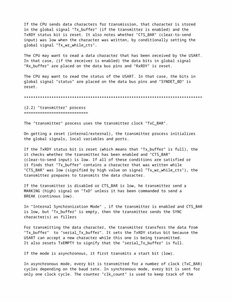
If the CPU sends data characters for transmission, that character is stored in the global signal "Tx_buffer" (if the transmitter is enabled) and the TxRDY status bit is reset. It also notes whether "CTS_BAR" (clear-to-send input) was low when the character was written, by conditionally setting the global signal "Tx_wr_while_cts".
The CPU may want to read a data character that has been received by the USART. In that case, (if the receiver is enabled) the data bits in global signal "Rx_buffer" are placed on the data bus pins and "RxRDY" is reset.
The CPU may want to read the status of the USART. In that case, the bits in global signal "status" are placed on the data bus pins and "SYNDET_BD" is reset.
++++++++++++++++++++++++++++++++++++++++++++++++++++++++++++++++++++++++++++++
(2.2) "transmitter" process ============================
The "transmitter" process uses the transmitter clock "TxC_BAR".
On getting a reset (internal/external), the transmitter process initializes the global signals, local variables and ports.
If the TxRDY status bit is reset (which means that "Tx_buffer" is full), the it checks whether the transmitter has been enabled and "CTS_BAR" (clear-to-send input) is low. If all of these conditions are satisfied or it finds that "Tx_buffer" contains a character that was written while "CTS_BAR" was low (signified by high value on signal "Tx_wr_while_cts"), the transmitter prepares to transmits the data character.
If the transmitter is disabled or CTS_BAR is low, he transmitter send a MARKING (high) signal on "TxD" unless it has been commanded to send a BREAK (continous low).
In "Internal Synchronization Mode" , if the transmitter is enabled and CTS_BAR is low, but "Tx_buffer" is empty, then the transmitter sends the SYNC character(s) as fillers
For transmitting the data character, the transmitter transfers the data from "Tx_buffer" to "serial_Tx_buffer". It sets the TxRDY status bit because the USART can accept a new character while this one is being transmitted. It also resets TxEMPTY to signify that the "serial_Tx_buffer" is full.
If the mode is asynchronous, it first transmits a start bit (low).
In asynchronous mode, every bit is transmitted for a number of clock (TxC_BAR) cycles depending on the baud rate. In synchronous mode, every bit is sent for only one clock cycle. The counter "clk_count" is used to keep track of the number of clock cycles that have passed. Bits are shifted out at the falling edge of TxC_BAR.

The data bits are then transmitted. The counter "char_bit_count" is used to count the number of character bits transmitted.
If parity is enabled, the appropriate (even/odd) parity bit is transmitted after the data bits.
Then, TxEMPTY is reset to signify that the "serial_Tx_buffer" is empty.
If the mode is asynchronous, then the required number of stop bits (high) are transmitted.
++++++++++++++++++++++++++++++++++++++++++++++++++++++++++++++++++++++++++++++
(2.3) "receiver" process =========================
The "receiver" process uses the transmitter clock "RxC_BAR".
On getting a reset (internal/external), the receiver process initializes the global signals, local variables and ports.
The receiver process is best understood by considering synchronous and asynchronous reception separately.
(2.3.1) Synchronous mode -------------------------
If the mode is synchronous and the receiver is enabled, then the receiver usually gets an "ENTER HUNT" command from the CPU, after a reset. The enter hunt command is used to achieve synchronization.
If the synchronization mode is internal, the receiver starts searching for a SYNC1 character, received serially at its "RxD" input. All bits in the "serial_Rx_buffer" are set to 0, to prevent a false SYNC1 detection, caused by bits that were already in the buffer. Then, the receiver starts shifting in one bit from the "RxD" input into its "serial_Rx_buffer", at every rising edge of RxC_BAR. At every rising edge (bit boundary), the contents of the "serial_Rx_buffer" are compared to SYNC1. If the contents match SYNC1 and the mode is Single-Sync, then synchronization has been achieved and the receiver gets out of HUNT mode. If the contents match SYNC1 but the mode is Double-Sync, the receiver has to assemble the next character and compare it to SYNC2. In either case, if parity has been programmed, the parity bit is received but not checked in HUNT mode. In Double-Sync mode, if the next character (assembled by shifing in bits from RxD into "serial_Rx_buffer" at every rising edge of RxC_BAR) matches SYNC2, then synchronization has been achieved and the receiver gets out of HUNT mode.
If the synchronization mode is external, the waits for a rising edge on SYNDET_BD. Once it gets the rising edge, synchronization has been achieved and the receiver gets out of HUNT mode.
Whenever the receiver achieves synchronization, SYNDET_BD is set and it starts assembling characters at the next clock edge. The receiver assembles data characters by shifting in bits from RxD into the "serial_Rx_buffer" at every rising edge of RxC_BAR, for the required number of clock cycles (depending on the number of bits per character). This is counted by the counter "char_bit_count".
If parity has been programmed, then the parity bit is received after the data bits and parity error is checked. The parity error flag is set, if error is detected.
The assembled is transferred from the "serial_Rx_buffer" to the "Rx_buffer".

( The CPU can read this buffer, via the "main" process.)
If the receiver is enabled, RxRDY is set to signal the CPU that a received character is waiting to be read.
If the previously received character (if any) is still unread by the CPU, then this new character overwrites it and overrun error is detected.
(2.3.2) Asynchronous mode -------------------------
If the mode is asynchronous and the receiver is enabled, then RxD is first sampled. If RxD is low, then the receiver is not ready to receive a start bit yet and it waits till the next rising edge on RxC_BAR and samples RxD again. If RxD stays low through a period equal to two character sequences, a break is detected. A counter "brk_count" is used to keep track of the number of clock cycles through which RxC_BAR has stayed low. This counter is reset whenever RxD goes high.
If RxD is high, the receiver is ready to receive a Start-Bit (low). It waits for a falling edge on Rxd (Start-Bit).
If the baud rate is 16X or 64X, the receiver waits for a number of RxC_BAR cycles equal to half the baud rate ( from now, we will call this number "half_baud" -- e.g. for 16X baud rate, "half_baud" will be 8 RxC_BAR cycles). Then it samples RxD again to see if its still low (False Start-Bit Detection Scheme). If its still low, then it proceeds to wait for another "half_baud" RxC_BAR cycles and then starts assembling the character. If its high, this is a false Start-Bit and it goes back to waiting for a falling edge on RxD.
For baud rate 1X, there is no false start-bit detection.
For baud rate 1X, data bits and parity bit (if enabled) are sampled at the next rising edge RxC_BAR edge.
For baud rate 16X or 64X, data bits and parity bit (if enabled) are sampled at their "nominal center". This is done by waiting for "half_baud" RxC_BAR cycles and then sampling RxD at the next RxC_BASR rising edge. Then, the receiver waits for "half_baud" RxC_BAR cycles. The variable "clk_count" is used to count the number of RxC_BAR cycles passed.
The receiver assembles data characters by shifting in bits from RxD into the "serial_Rx_buffer", for the required number character bits (counted by "char_bit_count").
If parity has been programmed, then the parity bit is received after the data bits and parity error is checked. The parity error flag is set, if error is detected.
The assembled is transferred from the "serial_Rx_buffer" to the "Rx_buffer". ( The CPU can read this buffer, via the "main" process.)
If the receiver is enabled, RxRDY is set to signal the CPU that a received character is waiting to be read.
If the previously received character (if any) is still unread by the CPU, then this new character overwrites it and overrun error is detected.
Then, the receiver checks the stop bit (high) at the next rising edge of clock. If RxD is low, then framing error flag is asserted.
****************************************************************************
(3) Global Signals and Local Variables ***************************************
(3.1) Global Signals --------------------
mode (8 bits) : ~~~~~~~~~~~~~~~ The mode word (coming from the CPU) is written into this
command (8 bits) : ~~~~~~~~~~~~~~~~~~ The command word (coming from the CPU) is written into this
SYNC1 (8 bits) : ~~~~~~~~~~~~~~~~ The SYNC1 character (coming from the CPU) is written into this. (Only in internal synchronization mode.)
SYNC2 (8 bits) : ~~~~~~~~~~~~~~~~ The SYNC2 character (coming from the CPU) is written into this. (Only in internal synchronization mode.)
SYNC_mask (8 bits) : ~~~~~~~~~~~~~~~~~~~~ This is a template (masking word that depends on the number of bits per character) used for comparing received characters to the SYNC character(s). (Only in internal synchronization mode.)
Tx_buffer (8 bits) : ~~~~~~~~~~~~~~~~~~~~ The data character to be transmitted (coming from CPU) is placed in this.
Rx_buffer (8 bits) : ~~~~~~~~~~~~~~~~~~~~ The data character received (serially at the RxD input) is placed in this. It may be read by the CPU.
Tx_wr_while_cts (1 bit) : ~~~~~~~~~~~~~~~~~~~~~~~~~ The setting of this bit signifies that the data for transmission (coming from the CPU) was written into the USART while CTS_BAR was low. The setting of this bit means that the USART must transmit this data even if CTS_BAR goes high subsequently.
baud_clocks (8 bits) : ~~~~~~~~~~~~~~~~~~~~~~ This stores the number of clock cycles per bit (depends on baud rate).
stop_clocks (8 bits) : ~~~~~~~~~~~~~~~~~~~~~~ This stores the number of stop bit clock cycles (depends on baud rate and number of clock cycles). Only for Asynchronous mode.
brk_clocks (11 bits) : ~~~~~~~~~~~~~~~~~~~~~~ This stores the number of clock cycles (two full character sequences) through which RxD has to stay low in order to detect a Break. (Only for Asynchronous mode)
chars (4 bits) : ~~~~~~~~~~~~~~~~

This stores the number of bits per character.
Note : The signal "status" and the ports "SYNDET_BD, RxRDY" are written to by more than one process. So, we split them up into many "sub-signals" (one for each writing-process e.g. "status_Rx" for the "status" sub-signal for the "receiver" process.).
Whenever any process writes to its own "sub-signal", we assign the new value to the actual signal. This "writing" is monitored by the trigger signals, which is toggled on any write. (e.g. "trigger_status_Rx" is the trigger signal for "status_Rx") This assignment of the new value is done inside a "triggering" block.
Whenever the signal has to be read inside any process , we read the actual signal (e.g. the receiver reads the "status" signal ) and not the "sub-signal" (e.g. the receiver does not read "status_Rx").
status (8 bits) : ~~~~~~~~~~~~~~~~~ This stores the current version status word.
status_main (8 bits) : ~~~~~~~~~~~~~~~~~~~~~~ This is the "main" process "sub-signal" (Please see "Note" above) for the "status" signal.
trigger_status_main (8 bits) : ~~~~~~~~~~~~~~~~~~~~~~~~~~~~~~ This is the "trigger signal" for "sub-signal" "status_main". (Please see "Note" above) status_Rx (8 bits) : ~~~~~~~~~~~~~~~~~~~~~~ This is the "receiver" process "sub-signal" (Please see "Note" above) for the "status" signal.
trigger_status_Rx (8 bits) : ~~~~~~~~~~~~~~~~~~~~~~~~~~~~ This is the "trigger signal" for "sub-signal" "status_Rx". (Please see "Note" above) status_Tx (8 bits) : ~~~~~~~~~~~~~~~~~~~~~~ This is the "transmitter" process "sub-signal" (Please see "Note" above) for the "status" signal.
trigger_status_Tx (8 bits) : ~~~~~~~~~~~~~~~~~~~~~~~~~~~~ This is the "trigger signal" for "sub-signal" "status_Tx". (Please see "Note" above) SYNDET_BD_main (8 bits) : ~~~~~~~~~~~~~~~~~~~~~~ This is the "main" process "sub-signal" (Please see "Note" above) for the "SYNDET_BD" port.
trigger_SYNDET_BD_main (8 bits) : ~~~~~~~~~~~~~~~~~~~~~~~~~~~~~~ This is the "trigger signal" for "sub-signal" "SYNDET_BD_main". (Please see "Note" above) SYNDET_BD_Rx (8 bits) : ~~~~~~~~~~~~~~~~~~~~~~ This is the "receiver" process "sub-signal" (Please see "Note" above) for the

"SYNDET_BD" port.
trigger_SYNDET_BD_Rx (8 bits) : ~~~~~~~~~~~~~~~~~~~~~~~~~~~~ This is the "trigger signal" for "sub-signal" "SYNDET_BD_Rx". (Please see "Note" above)
RxRDY_main (8 bits) : ~~~~~~~~~~~~~~~~~~~~~~ This is the "main" process "sub-signal" (Please see "Note" above) for the "RxRDY" port.
trigger_RxRDY_main (8 bits) : ~~~~~~~~~~~~~~~~~~~~~~~~~~~~~~ This is the "trigger signal" for "sub-signal" "RxRDY_main". (Please see "Note" above) RxRDY_Rx (8 bits) : ~~~~~~~~~~~~~~~~~~~~~~ This is the "receiver" process "sub-signal" (Please see "Note" above) for the "RxRDY" port.
trigger_RxRDY_Rx (8 bits) : ~~~~~~~~~~~~~~~~~~~~~~~~~~~~ This is the "trigger signal" for "sub-signal" "RxRDY_Rx". (Please see "Note" above) SYNDET_BD_temp (8 bits) : ~~~~~~~~~~~~~~~~~~~~~ This is an intermediate signal used for writing values to the bi-directional "SYNDET_BD" port.
+++++++++++++++++++++++++++++++++++++++++++++++++++++++++++++++++++++++++++++
(3.2) Local Variables for "main" process -------------------------------------------
Note: Because signals dont get new values immediately on assignment, we need to use variables (mode_var, command_var, baud_clocks_var, stop_clocks_var, status_var, chars_var) which are the same as signals (mode, command, stop_clocks, stop_clocks, status, chars).
This is needed because the new values of these signals are used for further computation inside the "main" process.
mode_var (8 bits) : ~~~~~~~~~~~~~~~~~~~ Local variable that stores the "mode" word, used for local computation. (Same value as "mode" signal)
status_var (8 bits) : ~~~~~~~~~~~~~~~~~~~ Local variable that stores the "status" word, used for local computation. (Same value as "status" signal)
command_var (8 bits) : ~~~~~~~~~~~~~~~~~~~~~~ Local variable that stores the "command" word, used for local computation. (Same value as "command" signal)
baud_clocks_var (8 bits) : ~~~~~~~~~~~~~~~~~~~~~~~~~~ Local variable (same value as "baud_clocks" signal), used for local computation.

stop_clocks_var (8 bits) : ~~~~~~~~~~~~~~~~~~~~~~~~~~ Local variable (same value as "stop_clocks" signal), used for local computation.
chars_var (4 bits) : ~~~~~~~~~~~~~~~~~~~~ Local variable (same value as "chars" signal), used for local computation.
next_cpu_control_word (2 bits) : ~~~~~~~~~~~~~~~~~~~~~~~~~~~~~~~ This variable keeps track of which control word should come next. (
00 = mode word 01 = SYNC1 character 10 = SYNC2 character 11 = command word)
SYNC_var (8 bits) : ~~~~~~~~~~~~~~~~~~~ This is temporary variable into which the SYNC characters (coming from the CPU) are stored initially, before formatting.
temp (11 bits) : ~~~~~~~~~~~~~~~~ This is a temporary variable, used in the computation of signal "brk_clocks"
++++++++++++++++++++++++++++++++++++++++++++++++++++++++++++++++++++++++++++++
(3.3) Local Variables for "transmitter" process -----------------------------------------------
parity (1 bit) : ~~~~~~~~~~~~~~~~ Temporary variable used in parity biy computation.
serial_Tx_buffer (8 bits) : ~~~~~~~~~~~~~~~~~~~~~~~~~~~ This is the serial transmission buffer from which data bits are shifted out (to "TxD") at clock ("TxC_BAR") edges.
store_Tx_buffer (8 bits) : ~~~~~~~~~~~~~~~~~~~~~~~~~~ This variable stores a copy of the data being transmitted. Its used in parity computation.
clk_count (8 bits) : ~~~~~~~~~~~~~~~~~~~~ This is a counter, used to count the number of clock cycles per bit. (Used primarily in Asynchronous mode, where baud rate is not equal to clock rate.)
char_bit_count (8 bits) : ~~~~~~~~~~~~~~~~~~~~~~~~~ This is a counter, used to count the number of bits per character
++++++++++++++++++++++++++++++++++++++++++++++++++++++++++++++++++++++++++++++
(3.4) Local Variables for "receiver" process --------------------------------------------

parity (1 bit) : ~~~~~~~~~~~~~~~~ Temporary variable used in parity biy computation.
serial_Rx_buffer (8 bits) : ~~~~~~~~~~~~~~~~~~~~~~~~~~~ This is the serial receive buffer into which data bits are shifted in (from "RxD") at clock ("RxC_BAR") edges.
clk_count (8 bits) : ~~~~~~~~~~~~~~~~~~~~ This is a counter, used to count the number of clock cycles per bit. (Used primarily in Asynchronous mode, where baud rate is not equal to clock rate.)
char_bit_count (8 bits) : ~~~~~~~~~~~~~~~~~~~~~~~~~ This is a counter, used to count the number of bits per character
sync_shift (8 bits) : ~~~~~~~~~~~~~~~~~~~~~ This variables is used while searching for the SYNC1 character in "HUNT MODE" (Internal Sync-Detect Mode). It is used to compare the (received) bits in the "serial_Rx_buffer" to the SYNC1 character.
brk_count (11 bits) : ~~~~~~~~~~~~~~~~~~~~~ This is a counter that keeps track of the number of clock cycles (if any) through which "RxD" has been low. This is used for Break-Detection in Asynchronous Mode.
half_baud ( 8 bits) : ~~~~~~~~~~~~~~~~~~~~~ This variable stores a number that is equal to half the number of clock cycles per bit. (Used primarily for 16X and 64X baud rates in Asynchronous mode.) It is mainly used for sampling bits at their mid-points (16X and 64X bau rate)
status_var (8 bits) : ~~~~~~~~~~~~~~~~~~~~~ Temporary variable used in computation of "status".
got_sync ( 1 bit) : ~~~~~~~~~~~~~~~~~~~ This variable is used in "HUNT MODE" to check whether the programmed SYNC character(s) have been received. (Relevant only in Internal Sync-Detect Mode).
got_half_sync ( 1 bit) : ~~~~~~~~~~~~~~~~~~~ This variable is used primarily for Double Sync character mode (Internal Sync-Detect Mode). Its used outside "HUNT MODE". Its assertion means that SYNC1 has been received and SYNDET_BD should be asserted if SYNC2 is received next.
****************************************************************************