intel® ixp4xx product line of network processors and ... · intel® ixp4xx product line of network...
TRANSCRIPT

Intel® IXP4XX Product Line of Network Processors and IXC1100 Control Plane Processor: Understanding Big Endian and Little Endian ModesApplication Note
December 2003
Document Number: 254237-001
2 Application Note
Intel® IXP4XX Product Line of Network Processors and IXC1100 Control Plane Processor: Understanding Big Endian and Little Endian ModesContents
INFORMATION IN THIS DOCUMENT IS PROVIDED IN CONNECTION WITH INTEL® PRODUCTS. NO LICENSE, EXPRESS OR IMPLIED, BY ESTOPPEL OR OTHERWISE, TO ANY INTELLECTUAL PROPERTY RIGHTS IS GRANTED BY THIS DOCUMENT. EXCEPT AS PROVIDED IN INTEL'S TERMS AND CONDITIONS OF SALE FOR SUCH PRODUCTS, INTEL ASSUMES NO LIABILITY WHATSOEVER, AND INTEL DISCLAIMS ANY EXPRESS OR IMPLIED WARRANTY, RELATING TO SALE AND/OR USE OF INTEL PRODUCTS INCLUDING LIABILITY OR WARRANTIES RELATING TO FITNESS FOR A PARTICULAR PURPOSE, MERCHANTABILITY, OR INFRINGEMENT OF ANY PATENT, COPYRIGHT OR OTHER INTELLECTUAL PROPERTY RIGHT. Intel products are not intended for use in medical, life saving, life sustaining applications.
Intel may make changes to specifications and product descriptions at any time, without notice.
Designers must not rely on the absence or characteristics of any features or instructions marked “reserved” or “undefined.” Intel reserves these for future definition and shall have no responsibility whatsoever for conflicts or incompatibilities arising from future changes to them.
The Intel® IXP4XX Product Line of Network Processors and Intel® IXP400 Software may contain design defects or errors known as errata which may cause the product to deviate from published specifications. Current characterized errata are available on request.
Contact your local Intel sales office or your distributor to obtain the latest specifications and before placing your product order.
Copies of documents which have an ordering number and are referenced in this document, or other Intel literature may be obtained by calling 1-800-548-4725 or by visiting Intel's website at http://www.intel.com.
BunnyPeople, CablePort, Celeron, Chips, Dialogic, DM3, EtherExpress, ETOX, FlashFile, i386, i486, i960, iCOMP, InstantIP, Intel, Intel Centrino, Intel Centrino logo, Intel logo, Intel386, Intel486, Intel740, IntelDX2, IntelDX4, IntelSX2, Intel Inside, Intel Inside logo, Intel NetBurst, Intel NetMerge, Intel NetStructure, Intel SingleDriver, Intel SpeedStep, Intel StrataFlash, Intel Xeon, Intel XScale, IPLink, Itanium, MCS, MMX, MMX logo, Optimizer logo, OverDrive, Paragon, PDCharm, Pentium, Pentium II Xeon, Pentium III Xeon, Performance at Your Command, RemoteExpress, SmartDie, Solutions960, Sound Mark, StorageExpress, The Computer Inside., The Journey Inside, TokenExpress, VTune, and Xircom are trademarks or registered trademarks of Intel Corporation or its subsidiaries in the United States and other countries.*Other names and brands may be claimed as the property of others.
Copyright © 2003, Intel Corporation
Application Note 3
Intel® IXP4XX Product Line of Network Processors and IXC1100Control Plane Processor: Understanding Big Endian and Little Endian Modes
Contents
Contents1.0 Introduction ...............................................................................................................................7
1.1 Scope....................................................................................................................................71.2 Related Documents ..............................................................................................................71.3 Introduction to Intel® IXP4XX Product Line of Network Processors .....................................71.4 Acronyms..............................................................................................................................8
2.0 The Basics of Endianness ...................................................................................................92.1 Processor View of Endianness .............................................................................................92.2 Endianness Definition by Bus Specification........................................................................102.3 Endianness in Communication ...........................................................................................11
2.3.1 Network Data is Big-Endian...................................................................................122.4 The Nature of Endianness: Hardware or Software? ...........................................................122.5 Endianness When Memory is Shared ................................................................................12
3.0 Software Considerations and Implications.................................................................133.1 Coding Pitfalls — Little-Endian/Big-Endian.........................................................................133.2 Casting a Pointer Between Types of Different Sizes ..........................................................143.3 Network Stacks and Protocols............................................................................................143.4 Shared Data Example: LE Re-Ordering Data for BE Network Traffic.................................143.5 Best Practices in Coding of Endian-Independence ............................................................15
3.5.1 Avoid......................................................................................................................153.5.2 Do ..........................................................................................................................15
3.6 Macro Examples: Endian Conversion.................................................................................153.6.1 Macro Source Code...............................................................................................16
3.6.1.1 Endianness Format Conversions...........................................................16
4.0 Endianness Features of the Intel® IXP4XX Product Line of Network Processors and IXC1100 Control Plane Processor.................................................174.1 Supporting Little-Endian in the Intel® IXP425 Network Processor......................................184.2 Endian Modes of the Intel® IXP4XX Product Line of Network Processors and IXC1100
Control Plane Processor.....................................................................................................194.2.1 Big-Endian Mode ...................................................................................................204.2.2 Little Endian Address Coherence Mode ................................................................214.2.3 Little Endian Data Coherence Mode......................................................................224.2.4 Reasons for Choosing a Particular LE Coherency Mode ......................................23
4.3 Silicon Endianness Controls ...............................................................................................244.3.1 Hardware Switches................................................................................................244.3.2 Intel XScale® Core Endianness Mode...................................................................25
4.3.2.1 Little Endian Data Coherence Enable/Disable.......................................264.3.2.2 MMU Data/Address Coherence Select ..................................................264.3.2.3 PCI Bus Swap........................................................................................27
4.3.3 Summary of Silicon Controls..................................................................................274.4 Silicon Versions ..................................................................................................................27
5.0 Little-Endian Strategy in Intel® IXP400 Software and Associated BSPs ........295.1 APB Peripherals .................................................................................................................30
5.1.1 APB VxWorks*.......................................................................................................30
4 Application Note
Intel® IXP4XX Product Line of Network Processors and IXC1100 Control Plane Processor: Understanding Big Endian and Little Endian ModesContents
5.1.2 APB WinCE* .......................................................................................................... 305.2 AHB Memory-Mapped Registers ........................................................................................ 315.3 Intel® IXP400 Software Core Components.........................................................................31
5.3.1 Queue Manager Core Component — ixQMgr ....................................................... 315.3.2 NPE Download — ixNpeDl .................................................................................... 315.3.3 NPE Message Handler — ixNpeMh ...................................................................... 325.3.4 Ethernet Access Component — ixEthAcc ............................................................. 32
5.3.4.1 Data Plane ............................................................................................. 335.3.4.2 MBUF Header ........................................................................................ 335.3.4.3 MBUF Data Payload .............................................................................. 335.3.4.4 Learning Data Base Function ................................................................ 365.3.4.5 Ethernet Access MIB Statistics .............................................................. 375.3.4.6 Ethernet MAC ........................................................................................ 375.3.4.7 Intel® IXP400 Software EthAcc Summary ............................................. 37
5.3.5 ATM and HSS........................................................................................................ 385.4 PCI...................................................................................................................................... 38
5.4.1 WinCE* and VxWorks* .......................................................................................... 385.4.2 Eboot .....................................................................................................................38
5.5 Intel® IXP400 Software OS Abstraction.............................................................................. 395.6 VxWorks* Considerations ...................................................................................................405.7 Microsoft* Windows* CE (WinCE*)..................................................................................... 42
5.7.1 WinCE* Eboot........................................................................................................ 425.7.2 WinCE* BSP.......................................................................................................... 43
5.8 Software Versions............................................................................................................... 45
6.0 References ...............................................................................................................................45
A Memory Access in Endian Modes .................................................................................. 47
Figures1 32-Bit Formats .............................................................................................................................. 92 Endianness in Big-Endian-Only Software Release .................................................................... 183 Intel® IXP4XX Product Line of Network Processors and IXC1100 Control
Plane Processor Endianness Controls ....................................................................................... 254 Intel XScale® Core MMU First-Level Descriptor.........................................................................265 Ethernet Frame ((Big-endian)..................................................................................................... 346 One Half-Word-Aligned Ethernet Frame (LE Address-coherent) ...............................................357 Intel XScale® Core Read of IP Header (LE Data-Coherent) ...................................................... 368 VxWorks* Data-Coherent Swap Code........................................................................................ 419 User Process Space................................................................................................................... 4410 Memory Access in Little-Endian Mode ....................................................................................... 4711 Memory Access in Big-Endian Mode.......................................................................................... 48
Tables1 Processor View of Endianness...................................................................................................102 Intel XScale® Core Big Endian Writes in — and NPE
Reads to/from — SDRAM ..........................................................................................................203 IIntel XScale® Core Little Endian Writes in Address
Coherent Mode and NPE Reads to/from SDRAM...................................................................... 21
Application Note 5
Intel® IXP4XX Product Line of Network Processors and IXC1100Control Plane Processor: Understanding Big Endian and Little Endian Modes
Contents
4 Intel XScale® Core Little Endian Writes in Data-Coherent Mode and NPE Reads to/from SDRAM......................................................................................23
5 Intel® IXP4XX Product Line of Network Processors and IXC1100 Control Plane Processor Endian Hardware Summary ............................................................................27
6 Intel® IXP4XX Product Line of Network Processors and IXC1100 Control Plane Processor A0 Silicon Part Numbers .................................................................................28
7 Intel® IXP4XX Product Line of Network Processors and IXC1100 Control Plane Processor B0 Silicon Part Numbers .................................................................................28
8 Intel® IXP400 Software Macros ..................................................................................................399 Memory-Mapping Defines...........................................................................................................3910 Endian Conversion Macros.........................................................................................................4011 Intel® IXP400 Software Versions................................................................................................45
6 Application Note
Intel® IXP4XX Product Line of Network Processors and IXC1100 Control Plane Processor: Understanding Big Endian and Little Endian ModesContents
Revision History
Date Revision Description
December 2003 001 Initial release.

Intel® IXP4XX Product Line of Network Processors and IXC1100Control Plane Processor: Understanding Big Endian and Little Endian Modes
Introduction
Application Note 7
1.0 IntroductionThe Intel® IXP4XX Product Line of Network Processors and IXC1100 Control Plane Processor supports little endian and big endian operation. This document discusses the implications in each endian type, and what support is provided for big endian or little endian operation.
When discussing board-support package (BSP) issues for the Intel® IXP4XX product line and IXC1100 control plane processors, this document refers to the Intel® IXDP425 / IXCDP1100 Development Platform. It also assumes usage of B0 silicon for the Intel® IXP4XX product line processor.
Note: References to the Intel® IXP425 Network Processor apply to the entire Intel® IXP4XX product line.
1.1 ScopeThis document is intended for software engineers developing software or board-support packages (BSPs) that are reliant on endianness support in the processor.
1.2 Related Documents
1.3 Introduction to Intel® IXP4XX Product Line of Network ProcessorsThe Intel® IXP425 Network Processor is a highly integrated, versatile, single-chip processor that can be used in a variety of products that need network connectivity and high performance to run their unique software applications. The IXP425 network processor combines integration with support for multiple WAN and LAN technologies in a common architecture designed to meet requirements for high-end gateways, Voice over IP (VoIP) applications, wireless access points, SME routers, switches, security devices, Mini-DSLAMs (Digital Subscriber Line Access Multiplexers), xDSL line cards, industrial control and networked imaging applications.
The IXP4XX product line and IXC1100 control plane processors has a unique distributed processing architecture that speeds development for a range of applications. Each network processor combines a high-performance Intel XScale® Core with additional network processor engines (NPEs) to achieve wire-speed packet processing performance.
Document Document Number
Intel IXP4XX Product Line Programmer’s Guide 252539
Intel XScale® Microarchitecture Programmer’s Reference Manual 273473
Intel® IXP4XX Product Line and IXC1100 Control Plane Processors Datasheet 252479
Intel® IXP4XX Product Line and IXC1100 Control Plane Processors Developer’s Manual 252480
Intel® IXP4XX Product Line of Network Processors and IXC1100 Control Plane Processor: Understanding Big Endian and Little Endian ModesIntroduction
8 Application Note
Each member of the IXP4XX product line and IXC1100 control plane processors is a multi-functional processor that incorporates many advanced architecture features, including the Intel XScale core, compliance with the ARM* Version 5TE instruction set architecture (ISA), an industry-standard, 32-bit PCI controller, Universal Asynchronous Receiver and Transmitter (UART), PC133 SDRAM memory controller, and interrupt controller, Universal Serial Bus (USB), and Universal Test and Operation PHY Interface for ATM (UTOPIA) and have general-purpose input/output (GPIO), 133-MHz internal bus, Advanced High-Performance Bus (AHB) bridges, timers, an 8-Kbyte Queue Manager, internal-bus Performance Monitoring Unit (PMU), network processor engines (NPEs), and industry-standard Media Independent Interfaces (MII).
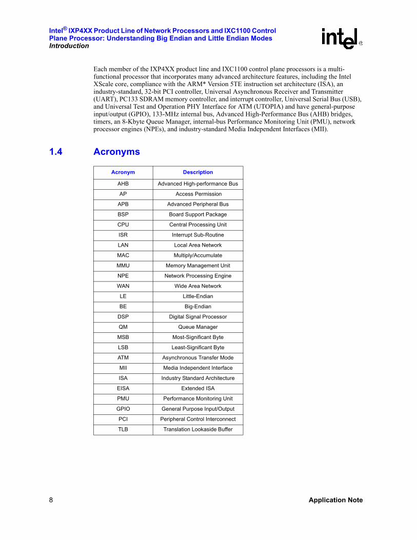
1.4 Acronyms
Acronym Description
AHB Advanced High-performance Bus
AP Access Permission
APB Advanced Peripheral Bus
BSP Board Support Package
CPU Central Processing Unit
ISR Interrupt Sub-Routine
LAN Local Area Network
MAC Multiply/Accumulate
MMU Memory Management Unit
NPE Network Processing Engine
WAN Wide Area Network
LE Little-Endian
BE Big-Endian
DSP Digital Signal Processor
QM Queue Manager
MSB Most-Significant Byte
LSB Least-Significant Byte
ATM Asynchronous Transfer Mode
MII Media Independent Interface
ISA Industry Standard Architecture
EISA Extended ISA
PMU Performance Monitoring Unit
GPIO General Purpose Input/Output
PCI Peripheral Control Interconnect
TLB Translation Lookaside Buffer
Intel® IXP4XX Product Line of Network Processors and IXC1100Control Plane Processor: Understanding Big Endian and Little Endian Modes
The Basics of Endianness
Application Note 9
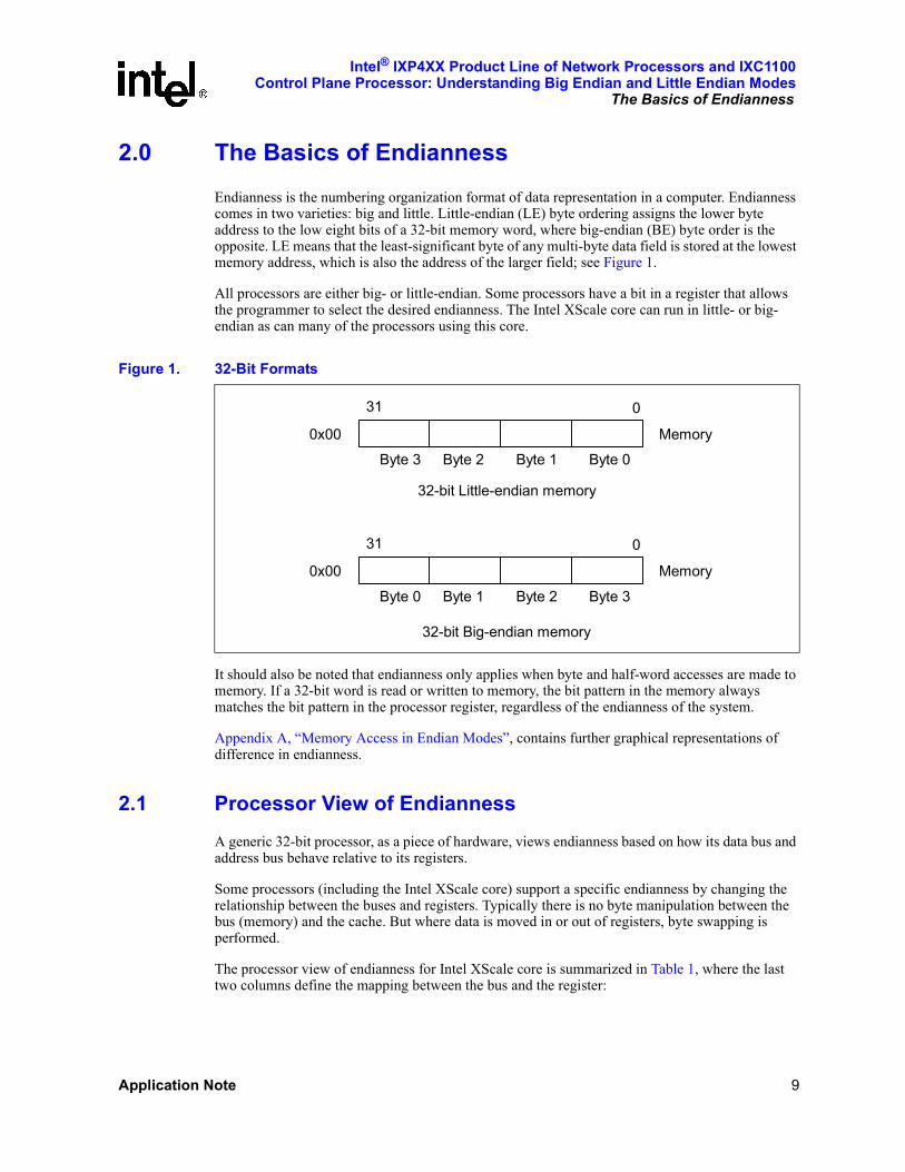
2.0 The Basics of EndiannessEndianness is the numbering organization format of data representation in a computer. Endianness comes in two varieties: big and little. Little-endian (LE) byte ordering assigns the lower byte address to the low eight bits of a 32-bit memory word, where big-endian (BE) byte order is the opposite. LE means that the least-significant byte of any multi-byte data field is stored at the lowest memory address, which is also the address of the larger field; see Figure 1.
All processors are either big- or little-endian. Some processors have a bit in a register that allows the programmer to select the desired endianness. The Intel XScale core can run in little- or big-endian as can many of the processors using this core.
It should also be noted that endianness only applies when byte and half-word accesses are made to memory. If a 32-bit word is read or written to memory, the bit pattern in the memory always matches the bit pattern in the processor register, regardless of the endianness of the system.
Appendix A, “Memory Access in Endian Modes”, contains further graphical representations of difference in endianness.
2.1 Processor View of EndiannessA generic 32-bit processor, as a piece of hardware, views endianness based on how its data bus and address bus behave relative to its registers.
Some processors (including the Intel XScale core) support a specific endianness by changing the relationship between the buses and registers. Typically there is no byte manipulation between the bus (memory) and the cache. But where data is moved in or out of registers, byte swapping is performed.
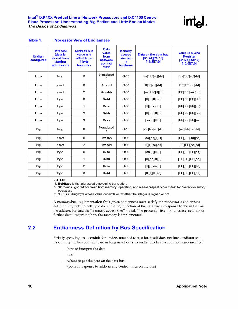
The processor view of endianness for Intel XScale core is summarized in Table 1, where the last two columns define the mapping between the bus and the register:
Figure 1. 32-Bit Formats
Byte 3 Byte 2 Byte 1 Byte 0
031
Memory0x00
32-bit Little-endian memory
Byte 0 Byte 1 Byte 2 Byte 3
031
Memory0x00
32-bit Big-endian memory
Intel® IXP4XX Product Line of Network Processors and IXC1100 Control Plane Processor: Understanding Big Endian and Little Endian ModesThe Basics of Endianness
10 Application Note
NOTES:1. Boldface is the addressed byte during translation.2. “II” means ‘ignored’ for “read from memory” operation, and means “repeat other bytes” for “write-to-memory”
operation.3. “FF” is a filling byte whose value depends on whether the integer is signed or not.
A memory/bus implementation for a given endianness must satisfy the processor’s endianness definition by putting/getting data on the right portion of the data bus in response to the values on the address bus and the “memory access size” signal. The processor itself is ‘unconcerned’ about further detail regarding how the memory is implemented.
2.2 Endianness Definition by Bus SpecificationStrictly speaking, as a conduit for devices attached to it, a bus itself does not have endianness. Essentially the bus does not care as long as all devices on the bus have a common agreement on:
— how to interpret the data and
— where to put the data on the data bus(both in response to address and control lines on the bus)
Table 1. Processor View of Endianness
Endian configured
Data size (data is
stored from starting
address m)
Address bus value m’s
offset from 4-byte
boundary
Data value from
software point of
view
Memory access size set
in hardware
Data on the data bus[31:24][23:16]
[15:8][7:0]
Value in a CPU Register
[31:24][23:16][15:8][7:0]
Little long 0 0xaabbccdd 0b10 [aa][bb][cc][dd] [aa][bb][cc][dd]
Little short 0 0xccdd 0b01 [II][II][cc][dd] [FF][FF][cc][dd]
Little short 2 0xaabb 0b01 [aa][bb][II][II] [FF][FF][aa][bb]
Little byte 0 0xdd 0b00 [II][II][II][dd] [FF][FF][FF][dd]
Little byte 1 0xcc 0b00 [II][II][cc][II] [FF][FF][FF][cc]
Little byte 2 0xbb 0b00 [II][bb][II][II] [FF][FF][FF][bb]
Little byte 3 0xaa 0b00 [aa][II][II][II] [FF][FF][FF][aa]
Big long 0 0xaabbccdd 0b10 [aa][bb][cc][dd] [aa][bb][cc][dd]
Big short 0 0xaabb 0b01 [aa][bb][II][II] [FF][FF][aa][bb]
Big short 2 0xccdd 0b01 [II][II][cc][dd] [FF][FF][cc][dd]
Big byte 0 0xaa 0b00 [aa][II][II][II] [FF][FF][FF][aa]
Big byte 1 0xbb 0b00 [II][bb][II][II] [FF][FF][FF][bb]
Big byte 2 0xcc 0b00 [II][II][cc][II] [FF][FF][FF][cc]
Big byte 3 0xdd 0b00 [II][II][II][dd] [FF][FF][FF][dd]
Intel® IXP4XX Product Line of Network Processors and IXC1100Control Plane Processor: Understanding Big Endian and Little Endian Modes
The Basics of Endianness
Application Note 11
However, to assist the achievement of such an agreement, all bus specifications explicitly or implicitly provide a common agreement for defining the big- or little-endian mode under which the bus is being used.
The commonly agreed definition is: when addressing a 4-byte aligned memory address, if the addressed byte occurs on bits [7:0] of the 32-bit data bus, the bus is working in little-endian mode, while if the addressed byte occurs on bits [31:24] of the 32-bit data bus, the bus is working in big-endian mode.
Following this definition, we have the following observations:
• AHB [see ARM Ltd., AMBA Specification, Rev. 2.0, May 1999] bus itself supports both endians. It is not clear in industry, which mode is used more often. The IXP425 uses AHB in big-endian mode, which is set by the way the memory controller hardware is connected to the AHB bus.
• APB bus spec [see ARM Ltd., AMBA Specification, Rev. 2.0, May 1999] does not mention anything about endianness, and therefore it is endian-neutral also. In the IXP425, APB is implemented in a special way such that its lower two address bits are completely ignored. Therefore, the APB bus in the IXP425 does not have the capability to address individual bytes at arbitrary locations. Also there is no byte swapping between AHB and APB. Any device on the APB bus of the IXP425, only responds to 4-byte addresses. The way the data lines of the APB bus are connected to the device’s data line, will be directly reflected on the APB data line and AHB data line. For example, the UART part of the hardware does have byte registers. These registers are hard-wired to the data bits [7:0] of the APB bus. As a result, these byte registers can be accessed always at a 4-byte address boundary by ignoring the other 3 bytes on bits [31:8] of the APB data lines. In this sense, the APB implementation on the IXP425 is endian-neutral.
• Although not specifically claimed in its specification (except in its configuration space) [see PCI Local Bus Specification, Draft, Revision 2.2, June 8, 1998], PCI is de facto a little-endian-only bus because it is always used in the little-endian mode. All devices on a PCI bus will appear as little endian devices.
• Expansion Bus
— All Texas Instruments* DSPs using HPI-8 or HPI-16 can be configured as little or big endian device. So the HPI bus itself is endian-neutral.
— Similarly, although technically the Motorola* style buses are endian-neutral, most devices use them in big-endian mode.
— The Intel-style bus has 16-bit data lines. While EISA/ISA buses do not specify any particular byte ordering, most devices use them in the Intel model, which is little endian.
2.3 Endianness in CommunicationWhen endianness is just a matter between a processor and a piece of memory, it is local and self-contained. But when data goes out of a local host domain, there must be a unique way to communicate integer numbers which use more than one byte per number. The main two areas regarding this are: binary data files and network communication.

Intel® IXP4XX Product Line of Network Processors and IXC1100 Control Plane Processor: Understanding Big Endian and Little Endian ModesThe Basics of Endianness
12 Application Note
Binary data stored in files is usually either big or little endian, depending on the computer operating system. This implies that binary data files cannot be exchanged universally without worrying about the endianness, even when data-header exchange is resolved. Various approaches are used for dealing with endianness in binary data files. Many programs and routines are readily available for handling endianness in binary data files.
Fortunately the network community has reached an agreement to always use big endian, i.e., MSB first-in time. Thus, big-endian is also called network-endian or network byte order.
2.3.1 Network Data is Big-Endian
TCP/IP defines the network byte order as big-endian. The protocol layers in the TCP/IP suite are defined to be big-endian. In other words, any 16- or 32-bit value within the various layer headers (e.g., an IP address, a packet length, or a checksum) must be sent and received with its MSB first.
Even if the computers at each end are little-endian, multi-byte integers passed between them must be converted to network byte order (big-endian) prior to transmission across the network, and converted back to little-endian at the receiving end.
The problems or incompatibilities in coding conventions or data interpretation tend to manifest when little-endian- and big-endian-format processors need to communicate with each other over a network. Network protocol stacks that need to be portable enough to run on architectures that may be big- or little-endian can be an area of possible software coding pitfalls. Ways to minimize these influences are described in Section 3.0 of this document.
2.4 The Nature of Endianness: Hardware or Software?A processor may be capable of supporting both LE and BE with the active form of endianness being dependant on a number of factors:
• How does the bus behave?A bus may also support both endians, its behavior in turn depending on:
— How is the memory system connected to the bus
Only correct matching between the processor’s mode, bus mode (i.e., how the bus and memory are connected), and the software will provide correct endian behavior.
Therefore, endianness in general is a hardware and software issue. However, a processor does not operate in a vacuum, instead it is part of a system. This implies that a hardware board with processors and memory components on it (unless specially designed to support both endians) would only support one endian mode, and software on any processor in the system must work with that same endian mode.
2.5 Endianness When Memory is SharedFollowing the definition of endianness from a software point of view, and assuming a piece of hardware can be extremely complex and intelligent, can a piece of memory be shared by two processors running under different endians achieve all “IDEAL_BI_ENDIAN” objectives at the same time? The objectives for such a system are as follows:
• Share long integers correctly (“correctly” is defined as one processor feels that the other processor is under the same endian as its own; for example, ProcessorBig write some data
Intel® IXP4XX Product Line of Network Processors and IXC1100Control Plane Processor: Understanding Big Endian and Little Endian Modes
Software Considerations and Implications
Application Note 13
starting from its view of address X, then if ProcessorLittle read the same amount of data starting from its own view of address X, the data read is the same as the data written by ProcessorBig);
• Share short integers correctly;
• Share byte integers correctly;
• Each processor has its own endianness consistency.
Unfortunately, the answer is NO even with help from the most sophisticated hardware.
3.0 Software Considerations and ImplicationsMuch literature is available explaining the software dependency on underlying hardware endianness.
In summary, software dependency on hardware endianness is manifested in these areas:
• Whenever a piece of software accesses a piece of memory which is treated as different sizes by manipulation of pointers in different parts of code, that code is endian-dependent. For example, IP address 0x01020304 can be treated as unsigned long. But if code needs to access byte 0x04 by manipulating pointers, the code becomes endian-dependent.
• If a piece of memory is accessed by other hardware or processors whose endian modes are independent of the processor on which the current software is running, then the current code become endian-dependent. For example, if network data is directly moved (DMA’ed) into memory as it is, then that particular piece of memory is always big-endian. As a result, the current code accessing that piece of memory becomes endian-dependent. If pointers are passed between processors, endian issues show immediately because of the fundamental difficulty as explained in Section 2.5).
• The above issues can occur in many places of an operating system, a hardware driver, or even a piece of application code. Some operating systems (e.g., VxWorks*) support both endians by different compilation switches.
• Compiler, debugger and other tools are generally endian-dependent because the translation between a high-level language (e.g., C) and assembly language is endian-dependent.
Under certain application assumptions, and when programming carefully, it is possible to have a piece of code that is endian-independent.
3.1 Coding Pitfalls — Little-Endian/Big-EndianWhen we talk about pitfalls in coding, we really are referring to possible incompatibilities in the interpretation of data between little-endian and big-endian machines. The following examples illustrate some instances where pitfalls in coding can be interpreted differently on LE verses BE machines (and thus should be avoided). There are also examples of how to code a module in a way that permits a consistent interpretation of data structures and data accesses in general, regardless of the endianness of the processor the code may be running on. Performance can also enter into the equation, especially if byte order needs to be frequently shuffled by the processor.
Intel® IXP4XX Product Line of Network Processors and IXC1100 Control Plane Processor: Understanding Big Endian and Little Endian ModesSoftware Considerations and Implications
14 Application Note
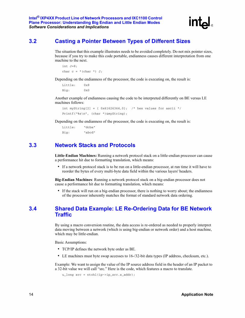
3.2 Casting a Pointer Between Types of Different SizesThe situation that this example illustrates needs to be avoided completely. Do not mix pointer sizes, because if you try to make this code portable, endianness causes different interpretation from one machine to the next.
int J=8;
char c = *(char *) J;
Depending on the endianness of the processor, the code is executing on, the result is: Little: 0x8
Big: 0x0
Another example of endianness causing the code to be interpreted differently on BE versus LE machines follows:
int myString[2] = { 0x61626364,0}; /* hex values for ascii */
Printf(“%s\n”, (char *)&myString);
Depending on the endianness of the processor, the code is executing on, the result is: Little: “dcba”
Big: “abcd”
3.3 Network Stacks and ProtocolsLittle-Endian Machines: Running a network protocol stack on a little-endian processor can cause a performance hit due to formatting translation, which means:
• If a network protocol stack is to be run on a little-endian processor, at run time it will have to reorder the bytes of every multi-byte data field within the various layers' headers.
Big-Endian Machines: Running a network protocol stack on a big-endian processor does not cause a performance hit due to formatting translation, which means:
• If the stack will run on a big-endian processor, there is nothing to worry about; the endianness of the processor inherently matches the format of standard network data ordering.
3.4 Shared Data Example: LE Re-Ordering Data for BE Network TrafficBy using a macro conversion routine, the data access is re-ordered as needed to properly interpret data moving between a network (which is using big-endian or network order) and a host machine, which may be little-endian.
Basic Assumptions:
• TCP/IP defines the network byte order as BE.
• LE machines must byte swap accesses to 16-/32-bit data types (IP address, checksum, etc.).
Example: We want to assign the value of the IP source address field in the header of an IP packet to a 32-bit value we will call “src.” Here is the code, which features a macro to translate.
u_long src = ntohl(ip->ip_src.s_addr);
Intel® IXP4XX Product Line of Network Processors and IXC1100Control Plane Processor: Understanding Big Endian and Little Endian Modes
Software Considerations and Implications
Application Note 15
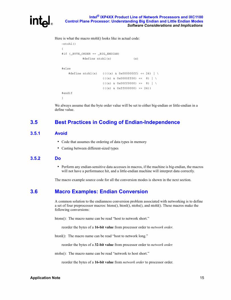
Here is what the macro ntohl() looks like in actual code:–ntohl()
{
#if (_BYTE_ORDER == _BIG_ENDIAN)
#define ntohl(x) (x)
#else
#define ntohl(x) ((((x) & 0x000000ff) << 24) | \
(((x) & 0x0000ff00) << 8) | \
(((x) & 0x00ff0000) >> 8) | \
(((x) & 0xff000000) >> 24))
#endif
}
We always assume that the byte order value will be set to either big-endian or little-endian in a define value.
3.5 Best Practices in Coding of Endian-Independence
3.5.1 Avoid
• Code that assumes the ordering of data types in memory
• Casting between different-sized types
3.5.2 Do
• Perform any endian-sensitive data accesses in macros, if the machine is big-endian, the macros will not have a performance hit, and a little-endian machine will interpret data correctly.
The macro example source code for all the conversion modes is shown in the next section.
3.6 Macro Examples: Endian ConversionA common solution to the endianness conversion problem associated with networking is to define a set of four preprocessor macros: htons(), htonl(), ntohs(), and ntohl(). These macros make the following conversions:
htons(): The macro name can be read “host to network short.”
reorder the bytes of a 16-bit value from processor order to network order.
htonl(): The macro name can be read “host to network long.”
reorder the bytes of a 32-bit value from processor order to network order.
ntohs(): The macro name can be read “network to host short.”
reorder the bytes of a 16-bit value from network order to processor order.

Intel® IXP4XX Product Line of Network Processors and IXC1100 Control Plane Processor: Understanding Big Endian and Little Endian ModesSoftware Considerations and Implications
16 Application Note
ntohl(): The macro name can be read “network to host long.”
reorder the bytes of a 32-bit value from network order to processor order.
3.6.1 Macro Source Code
If the processor on which the TCP/IP stack is to be run is itself also big-endian, each of the four macros in Section 3.6.1 will be defined to do nothing and there will be no run-time performance impact. If, however, the processor is little-endian, the macros will reorder the bytes appropriately. These macros would be used when building and parsing network packets and when socket connections are created.
By using macros to handle any possibly sensitive data conversions, the problem of dealing with network byte order (big-endian) on a little-endian machine will be eliminated. Ideally all network processors would have the same endianness, but because that is not true, understand and use the following macros as needed.
3.6.1.1 Endianness Format Conversions
#if defined(BIG_ENDIAN) /* the value of A will not be manipulated */
#define htons(A) (A)
#define htonl(A) (A)
#define ntohs(A) (A)
#define ntohl(A) (A)
#elif defined(LITTLE_ENDIAN) /* the value of A will be byte swapped */
#define htons(A) ((((A) & 0xff00) >> 8) | ((A) & 0x00ff) << 8))
#define htonl(A) ((((A) & 0xff000000) >> 24) | \
(((A) & 0x00ff0000) >> 8) | \
(((A) & 0x0000ff00) << 8) | \
(((A) & 0x000000ff) << 24))
#define ntohs htons
#define ntohl htohl
#else
#error "One of BIG_ENDIAN or LITTLE_ENDIAN must be #defined."
#endif
Intel® IXP4XX Product Line of Network Processors and IXC1100Control Plane Processor: Understanding Big Endian and Little Endian Modes
Endianness Features of the Intel® IXP4XX Product Line of Network Processors and
Application Note 17
4.0 Endianness Features of the Intel® IXP4XX Product Line of Network Processors and IXC1100 Control Plane ProcessorWithin the IXP4XX product line and IXC1100 control plane processors there are several devices connected via the system bus. The system consists of the Intel XScale core, network processing engines, PCI devices, APB peripherals and expansion bus peripherals. The Intel XScale core may operate in either little or big endian mode. The operation of the Intel XScale core in little endian mode creates a mixed-endian system.
Supporting more than one endian in a system may have two meanings:
• Case 1: Either big or little endian in the entire system but not mixed;
• Case 2: Some hardware components running in one endian mode while others running in the other endian mode.
The IDEAL_BI_ENDIAN objectives can not be achieved in the second case but can be achieved in the first case, as explained in Section 2.5. An IXP4XX product line and IXC1100 control plane processors chip or a IXP4XX product line and IXC1100 control plane processors chip-based board is a system of the second case.
In order to support more than one endianness as implied by “Case 2”, a hardware byte-swapping or address swizzling (or munging) facility is usually employed.
When a piece of memory is accessed by different pieces of hardware through different buses, a bus bridge is usually a good place to perform byte swapping or address swizzling. This ensures that each processor does not need to do any endian adjustments. Instead the processor assumes the underlying hardware behaves as if it is the same endianness as the processor.
Detail on the hardware settings can be found in the Intel® IXP4XX Product Line and IXC1100 Control Plane Processors Developer’s Manual, and the Intel® IXP4XX Product Line and IXC1100 Control Plane Processors Datasheet.
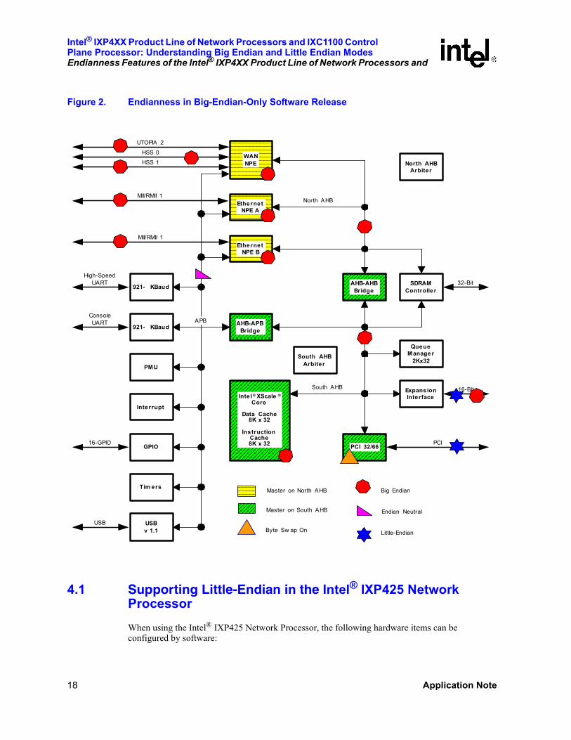
Figure 2 details the endianness of the different blocks of the IXP4XX product line and IXC1100 control plane processors when running a big endian software release.
Intel® IXP4XX Product Line of Network Processors and IXC1100 Control Plane Processor: Understanding Big Endian and Little Endian ModesEndianness Features of the Intel® IXP4XX Product Line of Network Processors and
18 Application Note
4.1 Supporting Little-Endian in the Intel® IXP425 Network ProcessorWhen using the Intel® IXP425 Network Processor, the following hardware items can be configured by software:
Figure 2. Endianness in Big-Endian-Only Software Release
WANNPE
EthernetNPE A
EthernetNPE B
921- KBaud
921- KBaud
PMU
Interrupt
GPIO
Tim ers
USBv 1.1
AHB-APBBridge
AHB-AHBBridge
SDRAMControlle r
North AHBArbiter
QueueManage r
2Kx32
ExpansionInterface
PCI 32/66
Inte l ® XScale ®
Core
Data Cache8K x 32
InstructionCache8K x 32
South AHB
APB
South AHBArbiter
North AHB
Master on North AHB
Master on South AHB
ConsoleUART
High-SpeedUART
16-GPIO
USB
MII/RMII 1
MII/RMII 1
HSS 1
HSS 0
UTOPIA 2
PCI
16-Bit
32-Bit
Big Endian
Endian Neutral
Little-EndianByte Sw ap On
Intel® IXP4XX Product Line of Network Processors and IXC1100Control Plane Processor: Understanding Big Endian and Little Endian Modes
Endianness Features of the Intel® IXP4XX Product Line of Network Processors and
Application Note 19
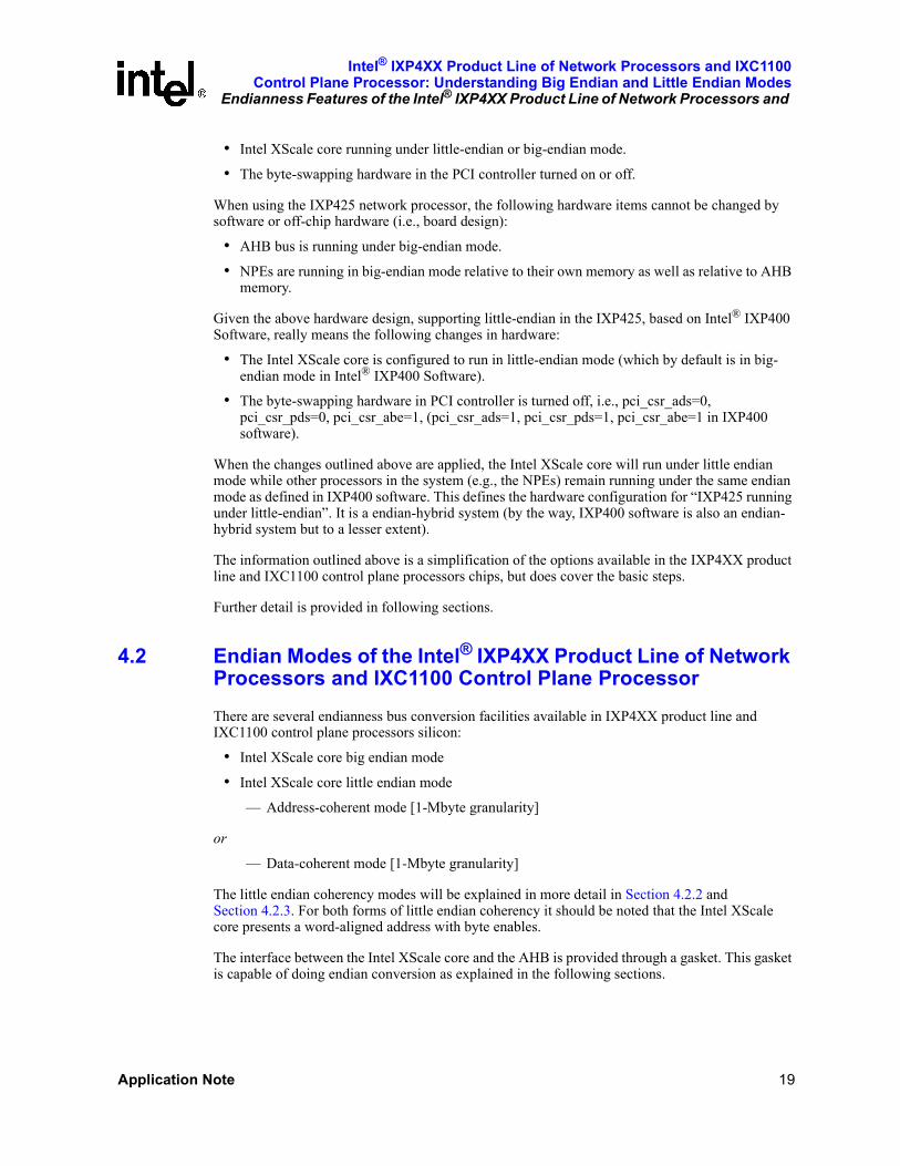
• Intel XScale core running under little-endian or big-endian mode.
• The byte-swapping hardware in the PCI controller turned on or off.
When using the IXP425 network processor, the following hardware items cannot be changed by software or off-chip hardware (i.e., board design):
• AHB bus is running under big-endian mode.
• NPEs are running in big-endian mode relative to their own memory as well as relative to AHB memory.
Given the above hardware design, supporting little-endian in the IXP425, based on Intel® IXP400 Software, really means the following changes in hardware:
• The Intel XScale core is configured to run in little-endian mode (which by default is in big-endian mode in Intel® IXP400 Software).
• The byte-swapping hardware in PCI controller is turned off, i.e., pci_csr_ads=0, pci_csr_pds=0, pci_csr_abe=1, (pci_csr_ads=1, pci_csr_pds=1, pci_csr_abe=1 in IXP400 software).
When the changes outlined above are applied, the Intel XScale core will run under little endian mode while other processors in the system (e.g., the NPEs) remain running under the same endian mode as defined in IXP400 software. This defines the hardware configuration for “IXP425 running under little-endian”. It is a endian-hybrid system (by the way, IXP400 software is also an endian-hybrid system but to a lesser extent).
The information outlined above is a simplification of the options available in the IXP4XX product line and IXC1100 control plane processors chips, but does cover the basic steps.
Further detail is provided in following sections.
4.2 Endian Modes of the Intel® IXP4XX Product Line of Network Processors and IXC1100 Control Plane ProcessorThere are several endianness bus conversion facilities available in IXP4XX product line and IXC1100 control plane processors silicon:
• Intel XScale core big endian mode
• Intel XScale core little endian mode
— Address-coherent mode [1-Mbyte granularity]
or
— Data-coherent mode [1-Mbyte granularity]
The little endian coherency modes will be explained in more detail in Section 4.2.2 and Section 4.2.3. For both forms of little endian coherency it should be noted that the Intel XScale core presents a word-aligned address with byte enables.
The interface between the Intel XScale core and the AHB is provided through a gasket. This gasket is capable of doing endian conversion as explained in the following sections.
Intel® IXP4XX Product Line of Network Processors and IXC1100 Control Plane Processor: Understanding Big Endian and Little Endian ModesEndianness Features of the Intel® IXP4XX Product Line of Network Processors and
20 Application Note
4.2.1 Big-Endian Mode
The following outlines the operation of the IXP4XX product line and IXC1100 control plane processors devices when the Intel XScale core is operating in big endian mode.
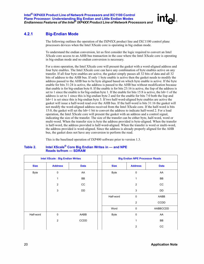
To understand the endian conversion, let us first consider the logic required to convert an Intel XScale core access to an AHB bus transaction in the case where the Intel XScale core is operating in big-endian mode and no endian conversion is necessary.
For a store operation, the Intel XScale core will present the gasket with a word-aligned address and four byte enables. The Intel XScale core can have any combination of byte enables active on any transfer. If all four byte enables are active, the gasket simply passes all 32 bits of data and all 32 bits of address to the AHB bus. If only 1 byte enable is active then the gasket needs to modify the address passed to the AHB bus to be byte aligned based on which byte enable is active. If the byte enable for bits 31:24 is active, the address is passed to the AHB bus without modification because that enable is for big-endian byte 0. If the enable is for bits 23:16 is active, the lisp of the address is set to 1 since the enable is for big-endian byte 1. If the enable for bits 15:8 is active, the lsb+1 of the address is set to 1 since this is big-endian byte 2 and for the enable for bits 7:0 both the lisp and lsb+1 is set since this is big-endian byte 3. If two half-word-aligned byte enables are active the gasket will issue a half-word read over the AHB bus. If the half-word is bits 31:16 the gasket will not modify the word-aligned address received from the Intel XScale core. If the half-word is bits 15:0, the gasket will set the lsb+1 bit to convert the address to indicate half-word 2. For a load operation, the Intel XScale core will present the gasket with an address and a control signal, indicating the size of the transfer. The size of the transfer can be either byte, half-word, word or multi-word. When the transfer size is byte the address provided is byte-aligned. When the transfer is half-word, the address provided is half-word-aligned. When the transfer is word or multi-word, the address provided is word-aligned. Since the address is already properly aligned for the AHB bus, the gasket does not have any conversion to perform the read.
This is the baselined operation of IXP400 software prior to version 1.3.
Table 2. Intel XScale® Core Big Endian Writes in — and NPE Reads to/from — SDRAM
Intel XScale : Big Endian Writes Big Endian NPE Processor Reads
Size Address Data Size Address Data
Byte 0 AA Byte 0 AA
1 BB 1 BB
2 CC 2 CC
3 DD 3 DD
Half-word 0 AABB
2 CCDD
Word 0 AABBCCDD
Half-word 0 AABB Byte 0 AA
2 CCDD 1 BB
2 CC

Intel® IXP4XX Product Line of Network Processors and IXC1100Control Plane Processor: Understanding Big Endian and Little Endian Modes
Endianness Features of the Intel® IXP4XX Product Line of Network Processors and
Application Note 21
4.2.2 Little Endian Address Coherence Mode
In this approach, the little-endian address is converted to big-endian.
For store operations the address conversion is the same as that for big-endian operation.
This is because even though the Intel XScale core is presenting little-endian information in its address and byte enables, the logic described above (Section 4.2.1) is simply generically converting address and byte-enables into a big-endian address.
For loads since byte or half-word-aligned addresses are provided for byte or half-word accesses, respectively, the byte or half-word addresses need to be converted to big-endian. For byte accesses this is performed by inverting both the lsb and lsb+1 address bits which effectively converts the byte alignment from 0, 1, 2 or 3 to 3, 2, 1 or 0, respectively. For half-word accesses the conversion is performed by inverting lsb+1 which effectively converts the half-word-alignment from 0 or 2 to 2 or 0, respectively. For word or multi-word accesses no conversion is necessary.
3 DD
Half-word 0 AABB
2 CCDD
Word 0 AABBCCDD
Word 0 AABBCCDD Byte 0 AA
1 BB
2 CC
3 DD
Half-word 0 AABB
2 CCDD
Word 0 AABBCCDD
Table 2. Intel XScale® Core Big Endian Writes in — and NPE Reads to/from — SDRAM (Continued)
Intel XScale : Big Endian Writes Big Endian NPE Processor Reads
Size Address Data Size Address Data
Table 3. IIntel XScale® Core Little Endian Writes in Address Coherent Mode and NPE Reads to/from SDRAM
Intel XScale® Core : Little Endian WritesAddress-Coherent (Address Swizzle) Big Endian NPE Processor Reads
Size Address Data Size Address Data
Byte 0 AA Byte 0 DD
1 BB 1 CC
Intel® IXP4XX Product Line of Network Processors and IXC1100 Control Plane Processor: Understanding Big Endian and Little Endian ModesEndianness Features of the Intel® IXP4XX Product Line of Network Processors and
22 Application Note
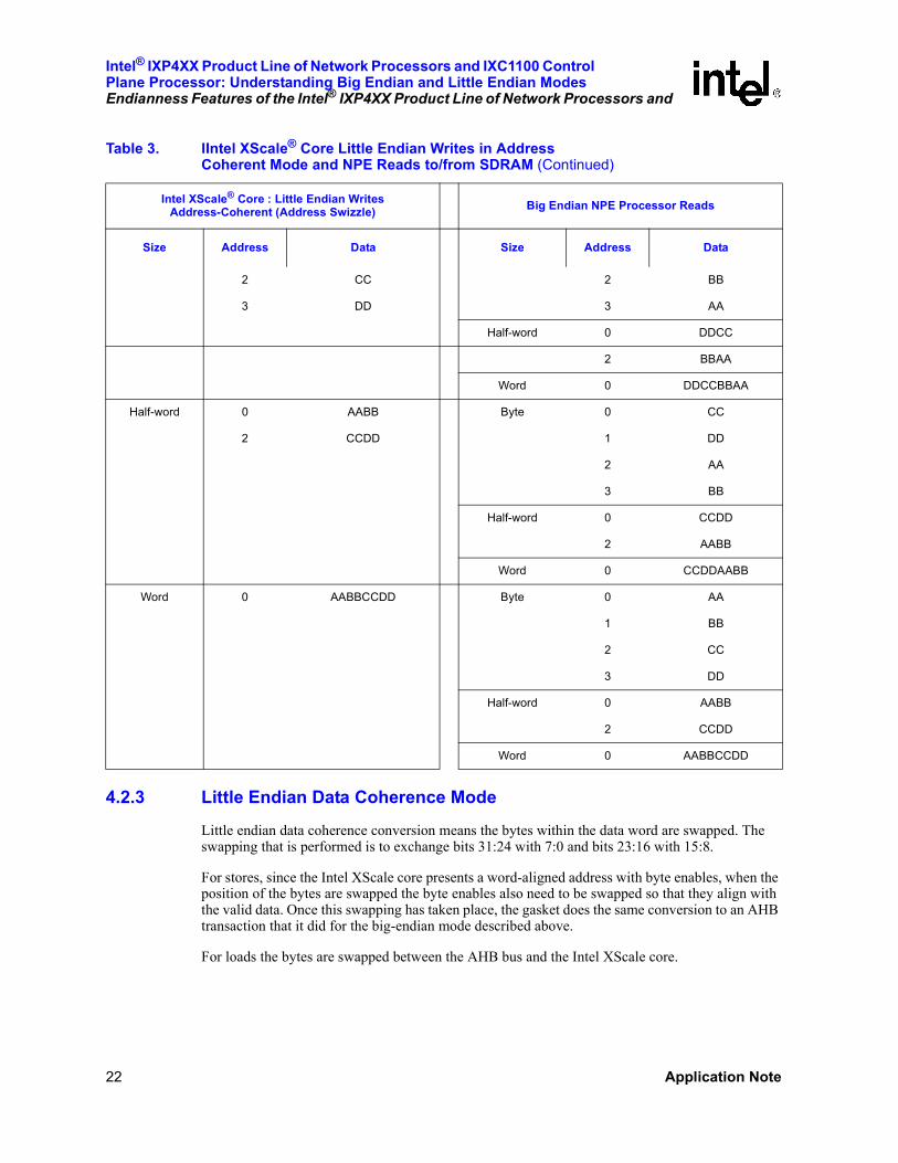
4.2.3 Little Endian Data Coherence Mode
Little endian data coherence conversion means the bytes within the data word are swapped. The swapping that is performed is to exchange bits 31:24 with 7:0 and bits 23:16 with 15:8.
For stores, since the Intel XScale core presents a word-aligned address with byte enables, when the position of the bytes are swapped the byte enables also need to be swapped so that they align with the valid data. Once this swapping has taken place, the gasket does the same conversion to an AHB transaction that it did for the big-endian mode described above.
For loads the bytes are swapped between the AHB bus and the Intel XScale core.
2 CC 2 BB
3 DD 3 AA
Half-word 0 DDCC
2 BBAA
Word 0 DDCCBBAA
Half-word 0 AABB Byte 0 CC
2 CCDD 1 DD
2 AA
3 BB
Half-word 0 CCDD
2 AABB
Word 0 CCDDAABB
Word 0 AABBCCDD Byte 0 AA
1 BB
2 CC
3 DD
Half-word 0 AABB
2 CCDD
Word 0 AABBCCDD
Table 3. IIntel XScale® Core Little Endian Writes in Address Coherent Mode and NPE Reads to/from SDRAM (Continued)
Intel XScale® Core : Little Endian WritesAddress-Coherent (Address Swizzle) Big Endian NPE Processor Reads
Size Address Data Size Address Data

Intel® IXP4XX Product Line of Network Processors and IXC1100Control Plane Processor: Understanding Big Endian and Little Endian Modes
Endianness Features of the Intel® IXP4XX Product Line of Network Processors and
Application Note 23
4.2.4 Reasons for Choosing a Particular LE Coherency Mode
The reason that both address and data-coherent endian conversion are provided is because there are different benefits and hazards to both approaches. If the only goal of the endian conversion was to make the Intel XScale core self-consistent, i.e., the Intel XScale core properly reads what it wrote, then either method would be sufficient. However, since the Intel XScale core must communicate with other processors and interfaces in the IXP425, it is beneficial to provide both methods.
To understand this we need to consider the benefits and hazards of both approaches by examining the details of how data is stored in memory, and in particular how the NPE will read and interpret that data. Table 2, Table 3 and Table 4 illustrate what is read back by the NPE when the Intel XScale core writes while in big-endian mode, little-endian address-coherent mode and little-endian
Table 4. Intel XScale® Core Little Endian Writes in Data-Coherent Mode and NPE Reads to/from SDRAM
Intel XScale® Core : Little Endian WritesData-Coherent (Byte Swizzle) NPE : Big Endian Processor Reads
Size Address Data Size Address Data
Byte 0 AA Byte 0 AA
1 BB 1 BB
2 CC 2 CC
3 DD 3 DD
Half-word 0 AABB
2 CCDD
Word 0 AABBCCDD
Half-word 0 AABB Byte 0 BB
2 CCDD 1 AA
2 DD
3 CC
Half-word 0 BBAA
2 DDCC
Word 0 BBAADDCC
Word 0 AABBCCDD Byte 0 DD
1 CC
2 BB
3 AA
Half-word 0 DDCC
2 BBAA
Word 0 DDCCBBAA
Intel® IXP4XX Product Line of Network Processors and IXC1100 Control Plane Processor: Understanding Big Endian and Little Endian ModesEndianness Features of the Intel® IXP4XX Product Line of Network Processors and
24 Application Note
data-coherent mode, respectively. The first thing to note is that when the Intel XScale core is in big endian mode, the NPE reads the data in the same format that it was written. When the Intel XScale core is in little endian address-coherent mode, words written by the Intel XScale core are in the same format when read by the NPE as words; however, byte accesses appear reversed and half-word accesses return the other half-word of the word. This mode has the benefit that if the Intel XScale core is writing a 32-bit address to memory, the NPE could read that address correctly without having to do any manual conversion. Additionally, when in this mode the Intel XScale core can read instructions which are in the same format that is needed for big-endian operation. That is, the same program image could be used for big-endian and little-endian modes.
When the Intel XScale core is in little endian data-coherent mode, bytes written by the Intel XScale core are in the same format when read as bytes by the NPE; however, the bytes within a word and half-word appear reversed. This endian conversion method is beneficial when data is written and read as bytes. Additionally, many commercially available software protocol stacks which were written to support both big and little endian modes assumed a data-coherent endian conversion and provides all the necessary byte swapping to correct words and half-words.
By providing both types of endian conversion through the use of the P-Attribute MMU bit the software has the flexibility to use whichever method is most convenient for that particular task.
4.3 Silicon Endianness Controls
4.3.1 Hardware Switches
There are four separate hardware endianness controls available to the software.
• Intel XScale core BE/LE mode
• Expansion Bus Control Register 2: LE data coherence enable
• MMU Page table “P” bit: LE (data/address) coherence selection
• PCI Bus swapping control

Intel® IXP4XX Product Line of Network Processors and IXC1100Control Plane Processor: Understanding Big Endian and Little Endian Modes
Endianness Features of the Intel® IXP4XX Product Line of Network Processors and
Application Note 25
Note: The default operation of the IXP4XX product line and IXC1100 control plane processors on reset is: Intel XScale core little-endian, address-coherent, MMU-disabled.
4.3.2 Intel XScale® Core Endianness Mode
The big and little endian modes are controlled by the B-bit of the Control Register Coprocessor 15, register 1, bit 7). The default mode at reset is little endian. To enable the big endian mode, the B bit must be set/cleared before performing any sub-word accesses to memory, or undefined results would occur. The bit takes effect even if the MMU is disabled. The following is assembly code to enable/clear the B-bit.
MACRO LITTLEENDIAN
MRC p15,0,a1,c1,c0,0
BIC a1,a1,#0x80 ;clear bit7 of register1 cp15
MCR p15,0,a1,c1,c0,0
ENDM
Figure 3. Intel® IXP4XX Product Line of Network Processors and IXC1100 Control Plane Processor Endianness Controls
Memory Sub System(SDRAM)
NPE’s
Addr/Data Bus Bus
Bus
XSCALE Xscale Endianessconverison logic
Addr/data bus Cache
MMUTables
LEcontrol(P-B
it)Xscale LE
Expa
nsio
n C
trlC
FG2
NPE’sNPE’s
Bus
PCI Controller
PCI B
us
PCI Endianess swap control
Under software control

Intel® IXP4XX Product Line of Network Processors and IXC1100 Control Plane Processor: Understanding Big Endian and Little Endian ModesEndianness Features of the Intel® IXP4XX Product Line of Network Processors and
26 Application Note
MACRO BIGENDIAN
MRC p15,0,a1,c1,c0,0
ORR a1,a1,#0x80 ;set bit7 of register1 cp15
MCR p15,0,a1,c1,c0,0
ENDM
The application code built to run on the system must be compiled to match the endianness. The compiler by default generates code in little endian mode. To produce the object code which is targeted for a big endian system, the compiler must be specified to work in big endian mode. For example, -mbig-endian switch must be specified for GNU* CC because the default is in little endian. For GNUPro* assembler, -EB switch would assemble the code for big endian. The library being used must have been compiled in the correct endian mode.
If the Intel XScale core is configured in big endian mode there is no conversion between the Intel XScale core and the core system bus, i.e., all subsequent endianness controls have no effect.
4.3.2.1 Little Endian Data Coherence Enable/Disable
The IXP4XX product line and IXC1100 control plane processors silicon allows for MMU control of the coherence mode used on a per-MMU-page basis. This capability is enabled/disabled via the BYTE_SWAP_EN bit (bit 8) of the exp_cnfg1 register, physical address 0xC4000024.
If Intel XScale core endianness is little endian then,
BYTE_SWAP_EN = 1, MMU P Bit control of address/data coherency.
BYTE_SWAP_EN = 0, Address coherence mode if LE selected,
The bit has no effect if the Intel XScale core is in big endian mode.
4.3.2.2 MMU Data/Address Coherence Select
The Intel XScale core within the IXP4XX product line and IXC1100 control plane processors of devices contains an extension to the MMU. The first-level page descriptor contains an additional bit (P) used to control the little endian coherence mode on a per-section basis (1 Mbyte of memory).
Note: This bit only has effect if the Intel XScale core is in LE mode and the BYTE_SWAP_EN of the Expansion Bus Configuration Register 1 is set.
Figure 4. Intel XScale® Core MMU First-Level Descriptor
31 30 29 28 27 26 25 24 23 22 21 20 19 18 17 16 15 14 13 12 11 10 9 8 7 6 5 4 3 2 1 0
Should be Zero (SBZ) 0 0
Course Page Table Address P Domain SBZ 0 1
Section Base Address SBZ TEX AP P Domain 0 C B 1 0
Fine Page Table Address SBZ P Domain SBZ 1 1
Intel® IXP4XX Product Line of Network Processors and IXC1100Control Plane Processor: Understanding Big Endian and Little Endian Modes
Endianness Features of the Intel® IXP4XX Product Line of Network Processors and
Application Note 27
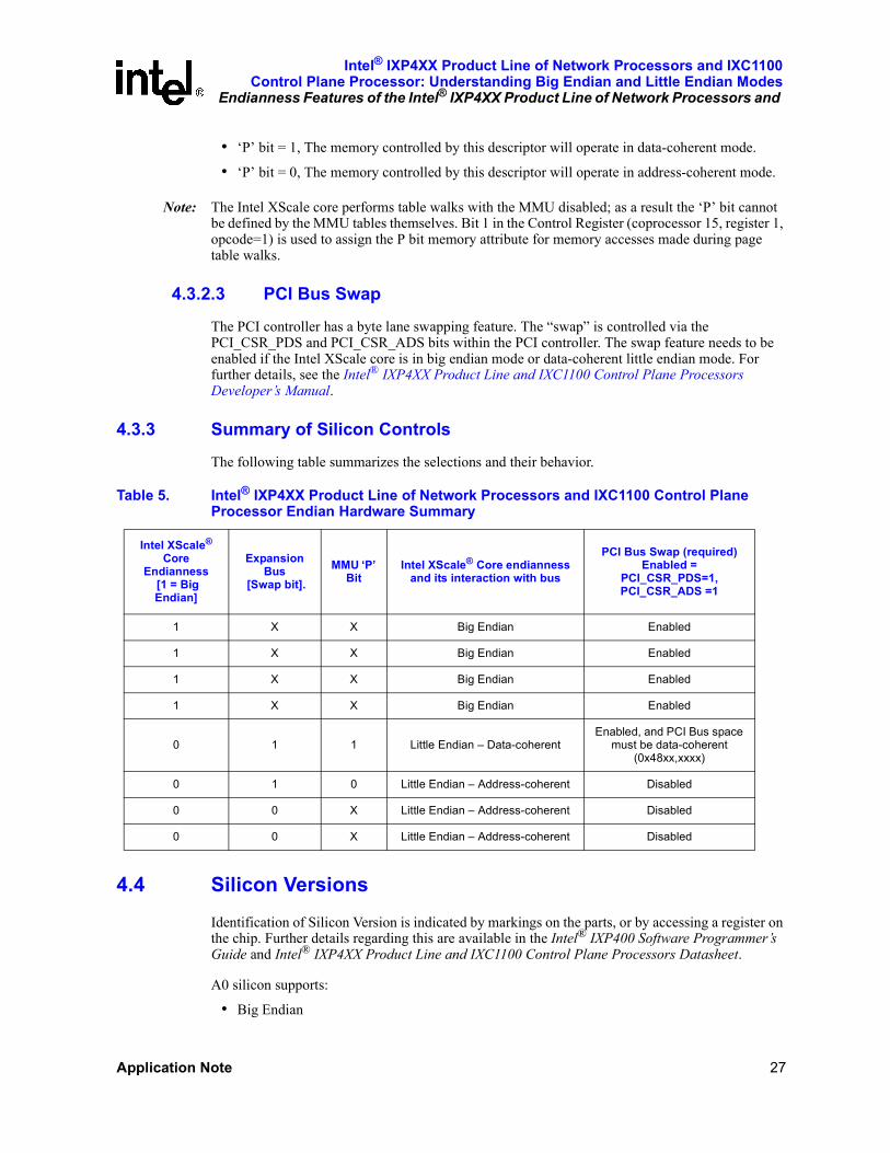
• ‘P’ bit = 1, The memory controlled by this descriptor will operate in data-coherent mode.
• ‘P’ bit = 0, The memory controlled by this descriptor will operate in address-coherent mode.
Note: The Intel XScale core performs table walks with the MMU disabled; as a result the ‘P’ bit cannot be defined by the MMU tables themselves. Bit 1 in the Control Register (coprocessor 15, register 1, opcode=1) is used to assign the P bit memory attribute for memory accesses made during page table walks.
4.3.2.3 PCI Bus Swap
The PCI controller has a byte lane swapping feature. The “swap” is controlled via the PCI_CSR_PDS and PCI_CSR_ADS bits within the PCI controller. The swap feature needs to be enabled if the Intel XScale core is in big endian mode or data-coherent little endian mode. For further details, see the Intel® IXP4XX Product Line and IXC1100 Control Plane Processors Developer’s Manual.
4.3.3 Summary of Silicon Controls
The following table summarizes the selections and their behavior.
4.4 Silicon VersionsIdentification of Silicon Version is indicated by markings on the parts, or by accessing a register on the chip. Further details regarding this are available in the Intel® IXP400 Software Programmer’s Guide and Intel® IXP4XX Product Line and IXC1100 Control Plane Processors Datasheet.
A0 silicon supports:
• Big Endian
Table 5. Intel® IXP4XX Product Line of Network Processors and IXC1100 Control Plane Processor Endian Hardware Summary
Intel XScale® Core
Endianness [1 = Big Endian]
Expansion Bus
[Swap bit].MMU ‘P’
BitIntel XScale® Core endianness
and its interaction with bus
PCI Bus Swap (required)Enabled =
PCI_CSR_PDS=1, PCI_CSR_ADS =1
1 X X Big Endian Enabled
1 X X Big Endian Enabled
1 X X Big Endian Enabled
1 X X Big Endian Enabled
0 1 1 Little Endian – Data-coherentEnabled, and PCI Bus space
must be data-coherent (0x48xx,xxxx)
0 1 0 Little Endian – Address-coherent Disabled
0 0 X Little Endian – Address-coherent Disabled
0 0 X Little Endian – Address-coherent Disabled
Intel® IXP4XX Product Line of Network Processors and IXC1100 Control Plane Processor: Understanding Big Endian and Little Endian ModesEndianness Features of the Intel® IXP4XX Product Line of Network Processors and
28 Application Note
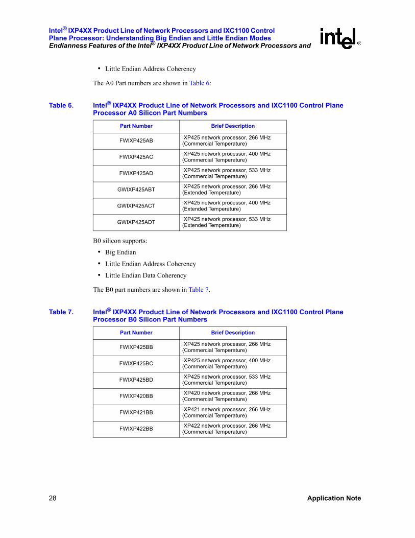
• Little Endian Address Coherency
The A0 Part numbers are shown in Table 6:
B0 silicon supports:
• Big Endian
• Little Endian Address Coherency
• Little Endian Data Coherency
The B0 part numbers are shown in Table 7.
Table 6. Intel® IXP4XX Product Line of Network Processors and IXC1100 Control Plane Processor A0 Silicon Part Numbers
Part Number Brief Description
FWIXP425AB IXP425 network processor, 266 MHz (Commercial Temperature)
FWIXP425AC IXP425 network processor, 400 MHz (Commercial Temperature)
FWIXP425AD IXP425 network processor, 533 MHz (Commercial Temperature)
GWIXP425ABT IXP425 network processor, 266 MHz (Extended Temperature)
GWIXP425ACT IXP425 network processor, 400 MHz (Extended Temperature)
GWIXP425ADT IXP425 network processor, 533 MHz (Extended Temperature)
Table 7. Intel® IXP4XX Product Line of Network Processors and IXC1100 Control Plane Processor B0 Silicon Part Numbers
Part Number Brief Description
FWIXP425BB IXP425 network processor, 266 MHz (Commercial Temperature)
FWIXP425BC IXP425 network processor, 400 MHz (Commercial Temperature)
FWIXP425BD IXP425 network processor, 533 MHz (Commercial Temperature)
FWIXP420BB IXP420 network processor, 266 MHz (Commercial Temperature)
FWIXP421BB IXP421 network processor, 266 MHz (Commercial Temperature)
FWIXP422BB IXP422 network processor, 266 MHz (Commercial Temperature)

Intel® IXP4XX Product Line of Network Processors and IXC1100Control Plane Processor: Understanding Big Endian and Little Endian Modes
Little-Endian Strategy in Intel® IXP400 Software and Associated BSPs
Application Note 29
5.0 Little-Endian Strategy in Intel® IXP400 Software and Associated BSPsThe Little Endian Strategy employed is discussed in relation to two different areas.
1. The IXDP425 / IXCDP1100 platform Board Support Packages.
2. The IXP400 software (Access Layer)
When adding support for Little Endian there were two factors taken into account in deciding where to use the different Little Endian modes of Address Coherency and Data Coherency.
1. The initial IXP400 software releases and Board Support Packages were all Big Endian–based.
2. IXP400 software support for Little Endian was required to operate on all the supported Little Endian Operating Systems.
The implications of this can be seen in two key Little Endian implementation decisions.
1. The Little Endian VxWorks Board Support Package uses Address Coherency. One of the properties of Address Coherency is that 32-bit accesses do not need to be swapped and, as most of the IXP4XX product line and IXC1100 control plane processors register accesses in the BSP are 32-bit accesses, it made sense to port the existing Big Endian BSP to Little Endian - Address Coherency.
2. The IXP400 software Little Endian implementation uses Data Coherency and furthermore all memory is mapped as Data Coherent. Data Coherency was required to ensure support for Microsoft* Windows* CE (WinCE). (More detail on this requirement is provided below) We did not want to have different Little Endian implementations of the IXP400 software for the different operating systems supported, and therefore we chose Data Coherency as the common implementation for all currently supported operating systems.
It should, however, be noted that the IXP400 software Little Endian implementation is designed in such a way that the coherency mode for any Access Layer component can be changed if so desired. The same is true for the memory map. There is no restriction placed on mapping memory as either Address or Data Coherent once that model is facilitated by the chosen operating-system MMU requirements. The choice of coherency mode is principally determined by the way the Operating system uses the memory management unit.
The files to consult within the IXP400 software are:\ixp425_xscale_sw\src\include\IxOsServicesEndianess.h\ixp425_xscale_sw\src\include\IxOsServicesComponents.h\ixp425_xscale_sw\src\include\IxOsServicesMemAccess.h
GWIXP425BBT IXP425 network processor, 266 MHz (Extended Temperature)
GWIXP425BCT IXP425 network processor, 400 MHz (Extended Temperature)
GWIXP425BDT IXP425 network processor, 533 MHz (Extended Temperature)
Table 7. Intel® IXP4XX Product Line of Network Processors and IXC1100 Control Plane Processor B0 Silicon Part Numbers (Continued)
Part Number Brief Description
Intel® IXP4XX Product Line of Network Processors and IXC1100 Control Plane Processor: Understanding Big Endian and Little Endian ModesLittle-Endian Strategy in Intel® IXP400 Software and Associated BSPs
30 Application Note
\ixp425_xscale_sw\src\include\ IxOsServicesMemMap.h
The remainder of this chapter details the IXP4XX product line and IXC1100 control plane processors Little Endian implementation as it relates to the two supported Little Endian operating systems of VxWorks and WinCE. It identifies the appropriate coherency mode per hardware component and explains the implications of each selection. It also contains a detailed look at the implications of the various endianess modes and how they relate to TCP/IP stack expectations.
Details on every component are not included, but rather an overview of certain components to provide insight on which coherency mode is used. Further details on the currently supported modes of each component are available in the Doxygen* notes provided with the IXP400 software.
Note: Due to the WinCE MMU usage model, and the granularity of control of the LE behavior available in the IXP4XX product line and IXC1100 control plane processors silicon, all components are placed in data-coherent mode. The requirement to operate in this mode is described in Section 5.7.
5.1 APB PeripheralsThe APB provides access to the following peripherals:
• Blocks specific to BSP
— UARTS
— Performance Monitoring Unit
— Interrupt Controller
— GPIO Controller
— Timer Block
• Blocks controlled by IXP400 software:
— NPE Message Handler and Execution control registers
— Ethernet MACs control
— Universal Serial Bus (USB)
5.1.1 APB VxWorks*
The APB peripherals are placed in address-coherent mode to nullify changes from the existing Big-Endian BSP.
5.1.2 APB WinCE*
The APB peripherals must be placed in data-coherent mode and will result in register definitions being swapped for all APB registers; this is handled in LE coherency macros used to access the APB space.
See Section 5.7 for WinCE data coherence chip-wide selection.
Intel® IXP4XX Product Line of Network Processors and IXC1100Control Plane Processor: Understanding Big Endian and Little Endian Modes
Little-Endian Strategy in Intel® IXP400 Software and Associated BSPs
Application Note 31
5.2 AHB Memory-Mapped RegistersThere are several other memory-mapped areas within a IXP4XX product line and IXC1100 control plane processorsdevice:
• Queue Manager; the configuration is covered in the Queue Manager Core Component, Section 5.3.1
• PCI, further details are provided in Section 5.4
— Control registers; these registers are all word-wide (32 bits).VxWorks: Address-coherent little endian mode.WinCE: Data-coherent little endian mode.
— PCI memory (AHB mapped, 0x48xx,xxxx Phy space); this space must be mapped data-coherent for both VxWorks and WinCE.
• Expansion Bus registers; these registers are all word-wide (32 bits)VxWorks: Address-coherent little endian mode.WinCE: Data-coherent little endian mode.
• SDRAM control registers; these registers are all word-wide (32 bits).VxWorks: Address-coherent little endian mode.WinCE: Data-coherent little endian mode.
5.3 Intel® IXP400 Software Core ComponentsIXP400 software contains several structural components used by all other IXP400 software access drivers. All of the software components are otherwise referred to as the Hardware Access Library. They provide software interfaces for control of the various hardware blocks within the IXP4XX product line and IXC1100 control plane processors. Further details on these software components are available in the Intel® IXP400 Software Programmer’s Guide.
Note: Changes to ixEthAcc listed here are indicative of the types of changes required in other components.
5.3.1 Queue Manager Core Component — ixQMgr
NPE Queue Manager Component provides the interface to the hardware queue manager block. All registers and hardware FIFOs are word-wide (32 bits); data-coherent LE mode is used.
5.3.2 NPE Download — ixNpeDl
This component is dependent on the IXP425 NPE (a,b,c) Message Handler and Execution Control registers. All registers are word-wide (32 bits), although such registers are best set up using LE address coherency mode, this would make the component have differing behavior in WinCE and VxWorks. As a result the NPE Execution control registers are mapped data-coherent. See Section 5.7.2 for further details specific to WinCE.
All register reads/writes occur via npeDl/include/ IxNpeDlMacros_p.h
IX_NPEDL_REG_READ()
Intel® IXP4XX Product Line of Network Processors and IXC1100 Control Plane Processor: Understanding Big Endian and Little Endian ModesLittle-Endian Strategy in Intel® IXP400 Software and Associated BSPs
32 Application Note
IX_NPEDL_REG_WRITE()
5.3.3 NPE Message Handler — ixNpeMh
Dependant on IXP425 NPE (a,b,c) Message Handler and Execution Control registers. All registers and hardware FIFOs are word-wide (32 bits).
• VxWorks
— Address-coherent LE mode is used and messages sent via the Message Handler interface, e.g., ixNpeMhMessageSend are passed as follows:typedef struct
{
UINT32 data[2]; /*the actual data of the message */
} IxNpeMhMessage;
Although the registers would be ideally accessed in address-coherent mode, a system-wide decision to put IXP400 software peripherals in data-coherent mode means the contents of the “data” within the Message Handler is modified by the underlying access-layer software.
• WinCEData-coherent LE mode is used. Messages sent via the Message Handler interface, e.g., ixNpeMhMessageSend are passed as follows:typedef struct
{
UINT32 data[2]; /*the actual data of the message */
} IxNpeMhMessage;
The content of the “data” within the Message Handler is modified by the underlying access-layer software.
All register reads/writes occur via npeMh/include/ IxNpeMhMacros_p.h
IX_NPEMH_REGISTER_READ ()
IX_NPEMH_REGISTER_READ_BITS()
IX_NPEMH_REGISTER_WRITE()
IX_NPEMH_REGISTER_WRITE_BITS()
5.3.4 Ethernet Access Component — ixEthAcc
The decision to set up the SDRAM in data-coherent LE mode is driven by the primary assumption that there will be more payload than control data structures exchanged between the NPEs and Intel XScale core. This approach also lends itself to using address-coherent mode for the control structures and should be easily implemented in a particular operating system environment if ever required in future OS porting.
Intel® IXP4XX Product Line of Network Processors and IXC1100Control Plane Processor: Understanding Big Endian and Little Endian Modes
Little-Endian Strategy in Intel® IXP400 Software and Associated BSPs
Application Note 33
5.3.4.1 Data Plane
The data plane interface for the Ethernet access component uses the queue manager component to send/receive messages between the Ethernet access and the Ethernet NPEs. All messages which are transferred are word-wide (32-bit) messages. These messages are modified by the underlying access layer because the queue manager hardware FIFOs are mapped using data-coherent little endian (as described in Section 5.3.1).
The Messages sent/received from the NPE contain a pointer reference to an MBuf header:
(M_BLK_HDR)typedef struct mHdr
{
struct mBlk *mNext; /* next buffer in chain */
struct mBlk *mNextPkt; /* next chain in queue/record */
char * mData; /* location of data */
int mLen; /* amount of data in this mBlk */
UCHAR mType; /* type of data in this mBlk */
UCHAR mFlags; /* flags; see below */
USHORT reserved;
} M_BLK_HDR;
The SDRAM is mapped using data coherency mode for all areas. This introduces two specific areas of consideration:
• NPE interpretation of the MBuf
• NPE interpretation of the mData payload.
5.3.4.2 MBUF Header
All entries in the MBUF header are word-wide1. As seen in Table 4, all word entries will be incorrectly interpreted by the NPE when the Intel XScale core logic is set up in data-coherent LE mode. As a result, all word entries used by the NPEs are swapped to/from the NPEs.
Note: If the MBUF headers were assigned to an address-coherent memory area, this swap would not be necessary; however, this would result in a mixed-coherency DRAM system, which would likely introduce a significant number of system data flow issues.
5.3.4.3 MBUF Data Payload
The Ethernet access component does not impose any alignment restrictions on the mData pointer within the MBUF header. The primary consideration in selecting the little endian coherence mode (as data-coherent) is the expectation the standard BSD IP stack places on the data format for payloads.
The BSD IP stack makes extensive use of the htons, htonl primitives to extract IP/UDP/TCP header information within the stack. These are described in Section 3.6.
1. The final word in the mbuf is comprised of Mbuf type, mbuf flags and a half-word pad; this also undergoes endianness conversion.
Intel® IXP4XX Product Line of Network Processors and IXC1100 Control Plane Processor: Understanding Big Endian and Little Endian ModesLittle-Endian Strategy in Intel® IXP400 Software and Associated BSPs
34 Application Note
BSD IP Stack summary:
• Bytes can be read with a byte pointer.
• All half-word reads must be half-word-aligned and use htons/ntohs for conversions.
• All word reads must be word-aligned and use htonl/ntohl for conversions.
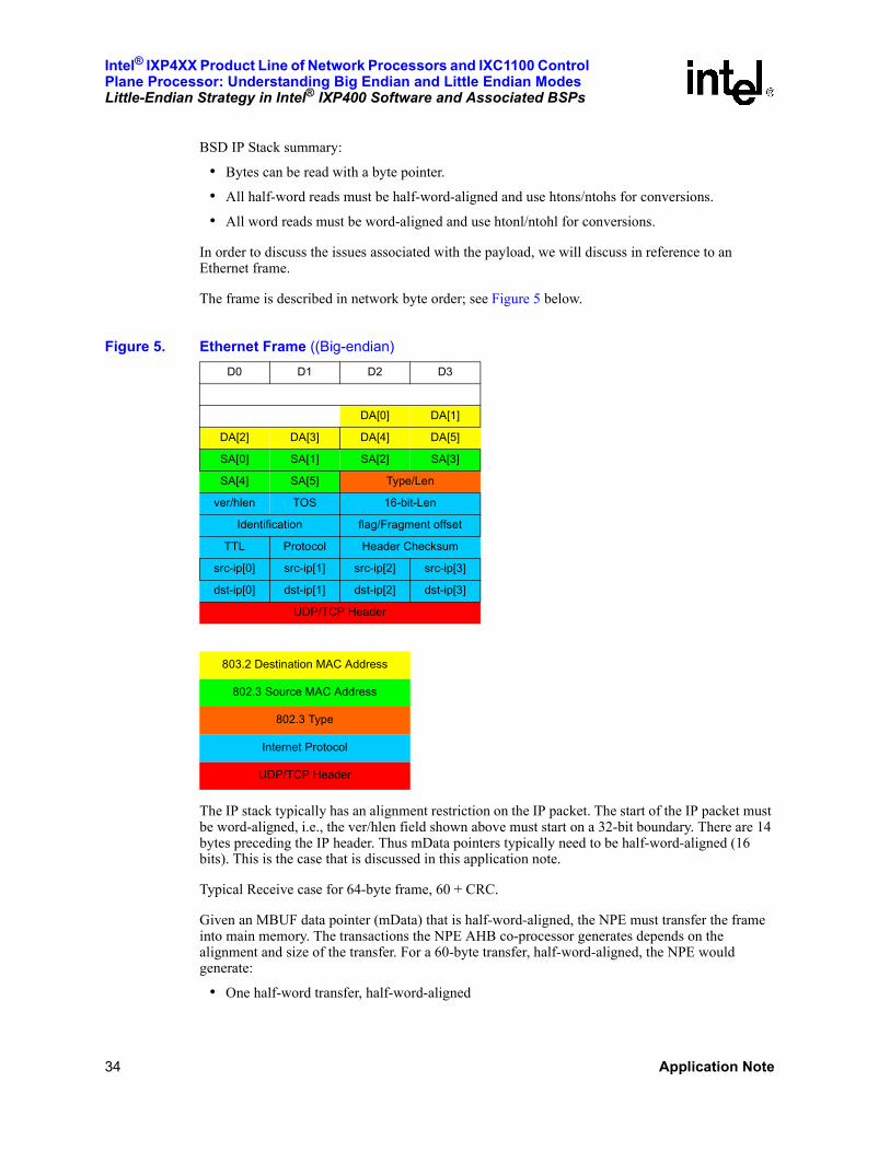
In order to discuss the issues associated with the payload, we will discuss in reference to an Ethernet frame.
The frame is described in network byte order; see Figure 5 below.
The IP stack typically has an alignment restriction on the IP packet. The start of the IP packet must be word-aligned, i.e., the ver/hlen field shown above must start on a 32-bit boundary. There are 14 bytes preceding the IP header. Thus mData pointers typically need to be half-word-aligned (16 bits). This is the case that is discussed in this application note.
Typical Receive case for 64-byte frame, 60 + CRC.
Given an MBUF data pointer (mData) that is half-word-aligned, the NPE must transfer the frame into main memory. The transactions the NPE AHB co-processor generates depends on the alignment and size of the transfer. For a 60-byte transfer, half-word-aligned, the NPE would generate:
• One half-word transfer, half-word-aligned
Figure 5. Ethernet Frame ((Big-endian)D0 D1 D2 D3
DA[0] DA[1]
DA[2] DA[3] DA[4] DA[5]
SA[0] SA[1] SA[2] SA[3]
SA[4] SA[5] Type/Len
ver/hlen TOS 16-bit-Len
Identification flag/Fragment offset
TTL Protocol Header Checksum
src-ip[0] src-ip[1] src-ip[2] src-ip[3]
dst-ip[0] dst-ip[1] dst-ip[2] dst-ip[3]
UDP/TCP Header
803.2 Destination MAC Address
802.3 Source MAC Address
802.3 Type
Internet Protocol
UDP/TCP Header

Intel® IXP4XX Product Line of Network Processors and IXC1100Control Plane Processor: Understanding Big Endian and Little Endian Modes
Little-Endian Strategy in Intel® IXP400 Software and Associated BSPs
Application Note 35
• 14 word burst transfers, word-aligned
• One half-word transfer, half-word-aligned.
This will result in the following payload (see Figure 6) written to SDRAM from the Intel XScale core (address-coherent).
The code below gives the read-out formation given the application of a conversion Macro. Effectively the header comes in Big-Endian and is then output in Little-Endian
The following shows the IP header structure and outlines how the payload would be read from the Intel XScale core in little endian data-coherent mode:struct iphdr {
__u8 version:4,
ihl:4; /* Offset 0*/
__u8 tos; /* Offset 1 byte*/
__u16 tot_len; /* Offset 2 bytes*/
__u16 id; /* Offset 4 bytes*/
__u16 frag_off; /* Offset 6 bytes*/
__u8 ttl; /* Offset 8 bytes*/
__u8 protocol; /* Offset 9 bytes*/
__u16 check; /* Offset 0xA bytes*/
Figure 6. One Half-Word-Aligned Ethernet Frame (LE Address-coherent)D0 D1 D2 D3
DA[1] DA[0]
DA[5] DA[4] DA[3] DA[2]
SA[3] SA[2] SA[1] SA[0]
Type/Len (swapped) SA[5] SA[4]
16-bit Total length (swapped) TOS ver/hlen
flag/Fragment offset (swap.) 16-bit Identif (swapped)
header checksum(swapped) Protocol TTL
src-ip[3] src-ip[2] src-ip[1] src-ip[0]
dst-ip[3] dst-ip[2] dst-ip[1] dst-ip[0]
UDP/TCP Header
803.2 Destination MAC Address
802.3 Source MAC Address
802.3 Type
Internet Protocol
UDP/TCP Header
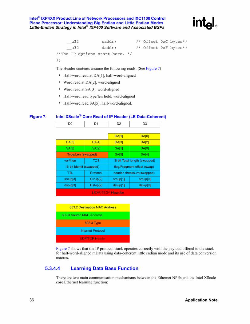
Intel® IXP4XX Product Line of Network Processors and IXC1100 Control Plane Processor: Understanding Big Endian and Little Endian ModesLittle-Endian Strategy in Intel® IXP400 Software and Associated BSPs
36 Application Note
__u32 saddr; /* Offset 0xC bytes*/
__u32 daddr; /* Offset 0xF bytes*/
/*The IP options start here. */
};
The Header contents assume the following reads: (See Figure 7)
• Half-word read at DA[1], half-word-aligned
• Word read at DA[2], word-aligned
• Word read at SA[3], word-aligned
• Half-word read type/len field, word-aligned
• Half-word read SA[5], half-word-aligned.
Figure 7 shows that the IP protocol stack operates correctly with the payload offered to the stack for half-word-aligned mData using data-coherent little endian mode and its use of data conversion macros.
5.3.4.4 Learning Data Base Function
There are two main communication mechanisms between the Ethernet NPEs and the Intel XScale core Ethernet learning function:
Figure 7. Intel XScale® Core Read of IP Header (LE Data-Coherent)D0 D1 D2 D3
DA[1] DA[0]
DA[5] DA[4] DA[3] DA[2]
SA[3] SA[2] SA[1] SA[0]
Type/Len (swapped) SA[5] SA[4]
ver/hlen TOS 16-bit Total length (swapped)
16-bit Identif (swapped) flag/Fragment offset (swap)
TTL Protocol header checksum(swapped)
src-ip[3] Src-ip[2] src-ip[1] src-ip[0]
dst-ip[3] Dst-ip[2] dst-ip[1] dst-ip[0]
UDP/TCP Header
803.2 Destination MAC Address
802.3 Source MAC Address
802.3 Type
Internet Protocol
UDP/TCP Header

Intel® IXP4XX Product Line of Network Processors and IXC1100Control Plane Processor: Understanding Big Endian and Little Endian Modes
Little-Endian Strategy in Intel® IXP400 Software and Associated BSPs
Application Note 37
• Message Handler interface
• Ethernet learning tree
The message passed to/from the NPE and Intel XScale core are transferred via the NPE Message Handler interface. All messages are word-wide entries, and as such will be transmitted correctly by calling the Message Handler interface. The messages are multi-word, and should be validated when transmission/decode.
The Ethernet learning tree is, however, stored in memory in data-coherent LE format. All words in the learning tree are swapped before transferring ownership to the NPE.
5.3.4.5 Ethernet Access MIB Statistics
The Ethernet NPEs maintain error statistics. The ixEthAccMibIIStatsGet & ixEthAccMibIIStatsGetClear. The statistics are recovered from the NPE via an SDRAM buffer. The buffer will be populated from the NPEs in big endian mode. As such, all words undergo a big endian to little endian (data-coherent) conversion before the results are returned to the user.
5.3.4.6 Ethernet MAC
All registers are mapped to the APB, and are accessed in word mode only (32 bits). Each OS will map the same.
• VxWorks: In general, the APB memory map is address-coherent, except for the Ethernet MACs. The decision was made to have the MACs use the same coherency modes for each OS. Thus the Ethernet MACs is accessed in data-coherent mode and has data swapping on all registers reads/writes.
• WinCE: The APB memory map is data-coherent and has data swapping on all registers reads/writes.
Src/ethAcc/include/ IxEthAccMac_p.h macros defined:
REG_READ()
REG_WRITE()
5.3.4.7 Intel® IXP400 Software EthAcc Summary
This is a summary of the changes that were made to the Ethernet access component, assuming NPE is big-endian and all SDRAM is in LE data-coherent mode.
• MBUF word pointers must be swapped prior to submission to the NPE.ixEthAccPortTxFrameSubmit
Note: The MBUF chain is walked and all MBUFs in a chain are updated.ixEthAccPortRxFreeReplenish
• MBUF word pointers are swapped on reception from the NPE before calling
— User functions registered via ixEthAccPortTxDoneCallbackRegister
— User function registered via ixEthAccTxBufferDoneCallbackRegister
• Ethernet Data Base (EthDB)

Intel® IXP4XX Product Line of Network Processors and IXC1100 Control Plane Processor: Understanding Big Endian and Little Endian ModesLittle-Endian Strategy in Intel® IXP400 Software and Associated BSPs
38 Application Note
— Endianness conversion of the Ethernet learning trees when ownership is transferred to/from the XScale <-> Ethernet NPEs
— Tree Writes : update ixEthDBNPETreeWrite
— Tree uploads : ixEthDBNPESyncScan
— Display : ixEthELTDumpTree
• MAC Statistics
— The memory used to return statistics from the NPE is endian converted before returning the data.
• Ethernet MAC registers are mapped in LE data-coherent mode.
Note: The coherency modes chosen for Intel’s LE implemenations for VxWorks and WinCE are summarized in Table 9.
5.3.5 ATM and HSS
Both ATM and HSS components pass descriptors between the Intel XScale core and NPEs. These descriptors undergo similar changes to those described above.
5.4 PCIThe primary consideration for PCI network drivers is the configuration of the byte swapping within the PCI controller itself; see Table 5.
The configuration is dependant on the-coherent mode of the SDRAM memory area. Both WinCE and VxWorks have the SDRAM memory controller in data-coherent mode.
5.4.1 WinCE* and VxWorks*
Importantly the PCI memory space must be configured in LE data-coherent mode. This is the physical memory area 0x4800,0000.
The PCI Configuration Space Register has PCI_CSR_IC, PCI_CSR_ABE, PCI_CSR_PDS, PCI_CSR_ADS set to ‘1’.
5.4.2 Eboot
Eboot SDRAM is configured in address-coherent mode, and requires the following set up.
The PCI memory space is configured in LE address-coherent mode. This is the physical memory area 0x4800,0000.
The PCI Configuration Space Register has PCI_CSR_ABE set to ‘1’ and PCI_CSR_PDS, PCI_CSR_ADS set to ‘0’.
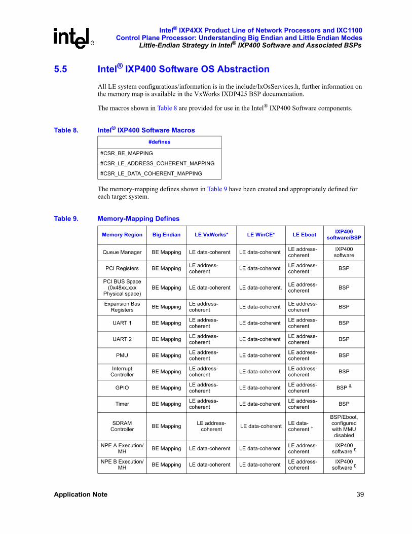
Intel® IXP4XX Product Line of Network Processors and IXC1100Control Plane Processor: Understanding Big Endian and Little Endian Modes
Little-Endian Strategy in Intel® IXP400 Software and Associated BSPs
Application Note 39
5.5 Intel® IXP400 Software OS AbstractionAll LE system configurations/information is in the include/IxOsServices.h, further information on the memory map is available in the VxWorks IXDP425 BSP documentation.
The macros shown in Table 8 are provided for use in the Intel® IXP400 Software components.
The memory-mapping defines shown in Table 9 have been created and appropriately defined for each target system.
Table 8. Intel® IXP400 Software Macros#defines
#CSR_BE_MAPPING
#CSR_LE_ADDRESS_COHERENT_MAPPING
#CSR_LE_DATA_COHERENT_MAPPING
Table 9. Memory-Mapping Defines
Memory Region Big Endian LE VxWorks* LE WinCE* LE Eboot IXP400 software/BSP
Queue Manager BE Mapping LE data-coherent LE data-coherent LE address-coherent
IXP400 software
PCI Registers BE Mapping LE address-coherent LE data-coherent LE address-
coherent BSP
PCI BUS Space (0x48xx,xxx
Physical space)BE Mapping LE data-coherent LE data-coherent. LE address-
coherent BSP
Expansion Bus Registers BE Mapping LE address-
coherent LE data-coherent LE address-coherent BSP
UART 1 BE Mapping LE address-coherent LE data-coherent LE address-
coherent BSP
UART 2 BE Mapping LE address-coherent LE data-coherent LE address-
coherent BSP
PMU BE Mapping LE address-coherent LE data-coherent LE address-
coherent BSP
Interrupt Controller BE Mapping LE address-
coherent LE data-coherent LE address-coherent BSP
GPIO BE Mapping LE address-coherent LE data-coherent LE address-
coherent BSP &
Timer BE Mapping LE address-coherent LE data-coherent LE address-
coherent BSP
SDRAM Controller BE Mapping LE address-
coherent LE data-coherent LE data-coherent +
BSP/Eboot, configured with MMU disabled
NPE A Execution/MH BE Mapping LE data-coherent LE data-coherent LE address-
coherentIXP400
software £
NPE B Execution/MH BE Mapping LE data-coherent LE data-coherent LE address-
coherentIXP400
software £

Intel® IXP4XX Product Line of Network Processors and IXC1100 Control Plane Processor: Understanding Big Endian and Little Endian ModesLittle-Endian Strategy in Intel® IXP400 Software and Associated BSPs
40 Application Note
NOTES:+ See Section 5.7.1 for further detail.& unchanged to minimize porting effort from Big Endian.£ Changed to permit validation under both VxWorks-LE and WinCE at the same time.
Table 10 shows the endian conversion macros that need to be mapped for developer usage.
5.6 VxWorks* ConsiderationsBoth the QM and NPE debug control registers (NPE message handler component - ixNpeMh) are placed in data-coherent LE mode. As the NPE debug registers are in APB space, and other APB registers are mapped in address-coherent mode, a data-coherent alias for the APB bus is defined.
NPE C Execution/MH BE Mapping LE data-coherent LE data-coherent LE address-
coherentIXP400
software £
Ethernet MAC 1 BE Mapping LE data-coherent LE data-coherent LE address-coherent
IXP400 software
Ethernet MAC 2 BE Mapping LE data-coherent LE data-coherent LE address-coherent
IXP400 software
USB Controller BE Mapping LE data-coherent LE data-coherent LE address-coherent
IXP400 software/BSP
SDRAM BE Mapping LE data-coherent LE data-coherentLE address and data-coherent +
IXP400 software/BSP
Table 9. Memory-Mapping Defines (Continued)
Memory Region Big Endian LE VxWorks* LE WinCE* LE Eboot IXP400 software/BSP
Table 10. Endian Conversion Macros
Macro Behavior Description
BE_XSTOBUSL() No swap Big Endian XScale to Bus Long
BE_XSTOBUSS() No swap Big Endian XScale to Bus Short
BE_BUSTOXSL() No swap Big Endian Bus to XScale Long
BE_BUSTOXSS() No swap Big Endian Bus to XScale Short
LE_AC_ XSTOBUSL() No swap Little Endian Address-Coherent XScale to Bus Long
LE_AC_ XSTOBUSS() Address Swap Little Endian Address-Coherent XScale to Bus Short
LE_AC_ BUSTOXSL() No swap Little Endian Address-Coherent Bus to XScale Long
LE_AC_ BUSTOXSS() Address Swap Little Endian Address-Coherent Bus to XScale Short
LE_DC_ XSTOBUSL() Data Word swap Little Endian Data-Coherent XScale to Bus Long
LE_DC_ XSTOBUSS() ½ Data Word swap Little Endian Data-Coherent Bus to XScale Short
LE_DC_ BUSTOXSL() Data Word swap Little Endian Data-Coherent Bus to XScale Long
LE_DC_ BUSTOXSS() ½ Data Word swap Little Endian Data-Coherent XScale to Bus Short
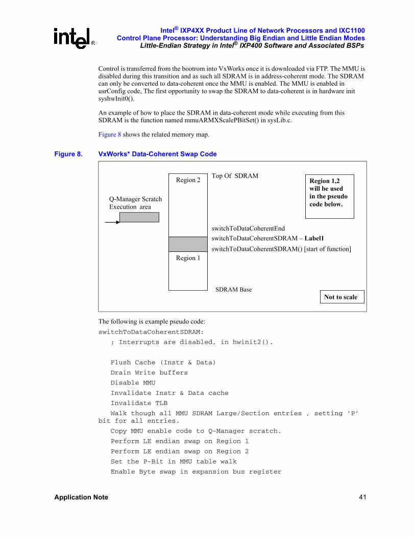
Intel® IXP4XX Product Line of Network Processors and IXC1100Control Plane Processor: Understanding Big Endian and Little Endian Modes
Little-Endian Strategy in Intel® IXP400 Software and Associated BSPs
Application Note 41
Control is transferred from the bootrom into VxWorks once it is downloaded via FTP. The MMU is disabled during this transition and as such all SDRAM is in address-coherent mode. The SDRAM can only be converted to data-coherent once the MMU is enabled. The MMU is enabled in usrConfig code, The first opportunity to swap the SDRAM to data-coherent is in hardware init syshwInit0().
An example of how to place the SDRAM in data-coherent mode while executing from this SDRAM is the function named mmuARMXScalePBitSet() in sysLib.c.
Figure 8 shows the related memory map.
The following is example pseudo code:switchToDataCoherentSDRAM:
; Interrupts are disabled, in hwinit2().
Flush Cache (Instr & Data)
Drain Write buffers
Disable MMU
Invalidate Instr & Data cache
Invalidate TLB
Walk though all MMU SDRAM Large/Section entries , setting ‘P’ bit for all entries.
Copy MMU enable code to Q-Manager scratch.
Perform LE endian swap on Region 1
Perform LE endian swap on Region 2
Set the P-Bit in MMU table walk
Enable Byte swap in expansion bus register
Figure 8. VxWorks* Data-Coherent Swap Code
switchToDataCoherentEnd switchToDataCoherentSDRAM – Label1 switchToDataCoherentSDRAM() [start of function]
SDRAM Base
Top Of SDRAM
Q-Manager Scratch Execution area
Region 1
Region 2 Region 1,2 will be used in the pseudo code below.
Not to scale
Intel® IXP4XX Product Line of Network Processors and IXC1100 Control Plane Processor: Understanding Big Endian and Little Endian ModesLittle-Endian Strategy in Intel® IXP400 Software and Associated BSPs
42 Application Note
Jump to scratch memory location
Enable MMU
Wait for action to complete
Jump to switchToDataCoherentSDRAM – Label1
Label1:
Enable Instr & Data cache.
Enable Branch Target buffer.
return
A similar implementation was required for execution in the VxWorks bootrom. The only caveat is that the SDRAM used to load the VxWorks image must be kept in address-coherent mode, as execution control will be transferred to that image with the MMU disabled.
5.7 Microsoft* Windows* CE (WinCE*)The following sections simply outline the implementation issues specific to WinCE. The principles outlined in the sections above still stand.
5.7.1 WinCE* Eboot
The use of data-coherent mode requires the MMU to be enabled. There are several implementation issues with enabling data-coherent operation for all of the SDRAM.There are no specific buffer management libraries supplied for operation within Eboot. As such it is reasonable to create a specific “payload buffer area” and set the attributes of this memory to data-coherent mode.
There is considerable flexibility in the MMU mappings for use within Eboot; it does not have the same considerations as those found in the kernel.
The address map is created via the declaration of OEMAddressTable found in Mempap.inc. The XScale startup code FwXS1.s create the MMU tables based on the contents of the OEMAddressTable.
The startup code creates the following virtual mappings:[8000 0000 --> 9FFF FFFF] = Cacheable, Bufferable
[A000 0000 --> BFFF FFFF] = Non Cacheable, non Bufferable
[C000 0000 --> D000 0000] = Non Cacheable, Non Bufferable, LE data coherent.
Driver Globals
There are a number of configuration items shared between Eboot and WinCE. These items are stored in the area defined by DRIVER_GLOBALS. The data is populated by Eboot and retrieved by WinCE. As the data will be retrieved via a data-coherent SDRAM mapping, Eboot must write to the driver globals area via the data-coherent alias.
Note: A key feature of Eboot is the transferring of the kernel image from a networked server into memory and subsequently transferring control to it, i.e., ‘jumping’ to the downloaded code. To do this, Eboot must disable the MMU and jump to the physical location of the kernel image. When the MMU is disabled, all SDRAM will be seen in address-coherent memory. As such, all instructions
Intel® IXP4XX Product Line of Network Processors and IXC1100Control Plane Processor: Understanding Big Endian and Little Endian Modes
Little-Endian Strategy in Intel® IXP400 Software and Associated BSPs
Application Note 43
fetched would be invalid. The work-around used in this scenario was to instead create a buffer area, allowing coherency to be resolved.
5.7.2 WinCE* BSP
The entire memory map must be placed in data-coherent LE mode. This is due to the sophisticated use of the MMU by WinCE. All Intel® IXP400 Software access components/codelets must be run in user mode. Each IXP400 software component would get a virtual address for a particular hardware resource via VirtualAlloc call. Multpile hardware resources could be mapped within a single 1-Mbyte, first-level descriptor. As a result we cannot define the ‘P’ bit attribute per hardware component. This forces us to have the ‘P’ = 1 for all memory, i.e., the entire system must run in data-coherent mode.
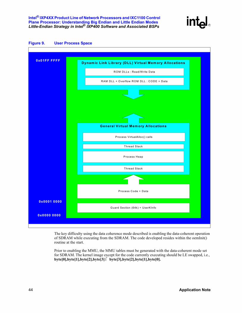
Intel® IXP4XX Product Line of Network Processors and IXC1100 Control Plane Processor: Understanding Big Endian and Little Endian ModesLittle-Endian Strategy in Intel® IXP400 Software and Associated BSPs
44 Application Note
The key difficulty using the data coherence mode described is enabling the data-coherent operation of SDRAM while executing from the SDRAM. The code developed resides within the oemInit() routine at the start.
Prior to enabling the MMU, the MMU tables must be generated with the data-coherent mode set for SDRAM. The kernel image except for the code currently executing should be LE swapped, i.e., byte[0],byte[1],byte[2],byte[3] ⌠ byte[3],byte[2],byte[1],byte[0].
Figure 9. User Process Space
Dynam ic Link Library (DLL) Virtual M em ory A llocations
General Virtual M em ory A llocations
Process Code + Data
Guard Section (64k) + UserKInfo
Process V irtualA lloc() calls
Thread Stack
P rocess Heap
Thread Stack
RO M DLLs : Read/W rite Data
RAM DLL + O verflow ROM DLL : CO DE + Data
0x01FF FFFF
0x0000 0000
0x0001 0000
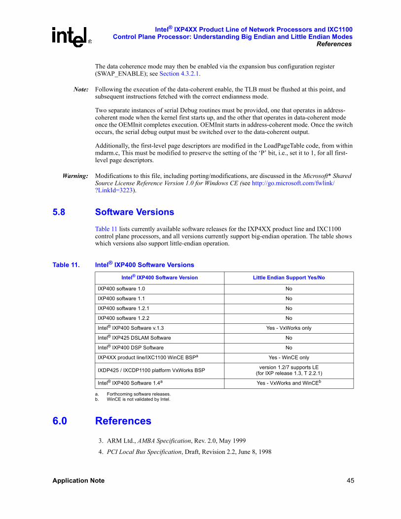
Intel® IXP4XX Product Line of Network Processors and IXC1100Control Plane Processor: Understanding Big Endian and Little Endian Modes
References
Application Note 45
The data coherence mode may then be enabled via the expansion bus configuration register (SWAP_ENABLE); see Section 4.3.2.1.
Note: Following the execution of the data-coherent enable, the TLB must be flushed at this point, and subsequent instructions fetched with the correct endianness mode.
Two separate instances of serial Debug routines must be provided, one that operates in address-coherent mode when the kernel first starts up, and the other that operates in data-coherent mode once the OEMInit completes execution. OEMInit starts in address-coherent mode. Once the switch occurs, the serial debug output must be switched over to the data-coherent output.
Additionally, the first-level page descriptors are modified in the LoadPageTable code, from within mdarm.c, This must be modified to preserve the setting of the ‘P’ bit, i.e., set it to 1, for all first-level page descriptors.
Warning: Modifications to this file, including porting/modifications, are discussed in the Microsoft* Shared Source License Reference Version 1.0 for Windows CE (see http://go.microsoft.com/fwlink/?LinkId=3223).
5.8 Software VersionsTable 11 lists currently available software releases for the IXP4XX product line and IXC1100 control plane processors, and all versions currently support big-endian operation. The table shows which versions also support little-endian operation.
6.0 References3. ARM Ltd., AMBA Specification, Rev. 2.0, May 1999
4. PCI Local Bus Specification, Draft, Revision 2.2, June 8, 1998
Table 11. Intel® IXP400 Software Versions
Intel® IXP400 Software Version Little Endian Support Yes/No
IXP400 software 1.0 No
IXP400 software 1.1 No
IXP400 software 1.2.1 No
IXP400 software 1.2.2 No
Intel® IXP400 Software v.1.3 Yes - VxWorks only
Intel® IXP425 DSLAM Software No
Intel® IXP400 DSP Software No
IXP4XX product line/IXC1100 WinCE BSPa
a. Forthcoming software releases.
Yes - WinCE only
IXDP425 / IXCDP1100 platform VxWorks BSP version 1.2/7 supports LE (for IXP release 1.3, T 2.2.1)
Intel® IXP400 Software 1.4a Yes - VxWorks and WinCEb
b. WinCE is not validated by Intel.

Intel® IXP4XX Product Line of Network Processors and IXC1100 Control Plane Processor: Understanding Big Endian and Little Endian ModesReferences
46 Application Note
5. http://www.pcisig.com/reflector/msg01668.html, a discussion on PCI bridge between little and big endian devices
6. Intel® IXP4XX Product Line and IXC1100 Control Plane Processors Developer’s Manual
7. Intel® IXP4XX Product Line and IXC1100 Control Plane Processors Datasheet
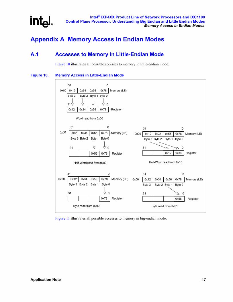
Intel® IXP4XX Product Line of Network Processors and IXC1100Control Plane Processor: Understanding Big Endian and Little Endian Modes
Memory Access in Endian Modes
Application Note 47
Appendix A Memory Access in Endian Modes
A.1 Accesses to Memory in Little-Endian ModeFigure 10 illustrates all possible accesses to memory in little-endian mode.
Figure 11 illustrates all possible accesses to memory in big-endian mode.
Figure 10. Memory Access in Little-Endian Mode
0
0x780x560x340x12
0
Memory (LE)0x12
31
31
0x00
Register
Byte 3 Byte 2 Byte 1 Byte 0
0x56 0x780x34
Word read from 0x00
0
0x780x56
0
Memory (LE)0x12
31
31
0x00
Register
Byte 3 Byte 2 Byte 1 Byte 0
0x56 0x780x34
Half-Word read from 0x00
0
0x340x12
0
Memory (LE)0x12
31
31
0x00
Register
Byte 3 Byte 2 Byte 1 Byte 0
0x56 0x780x34
Half-Word read from 0x10
0
0x78
0
Memory (LE)0x12
31
31
0x00
Register
Byte 3 Byte 2 Byte 1 Byte 0
0x56 0x780x34
Byte read from 0x00
0
0x56
0
Memory (LE)0x12
31
31
0x00
Register
Byte 3 Byte 2 Byte 1 Byte 0
0x56 0x780x34
Byte read from 0x01

Intel® IXP4XX Product Line of Network Processors and IXC1100 Control Plane Processor: Understanding Big Endian and Little Endian ModesMemory Access in Endian Modes
48 Application Note
This page is intentionally left blank.
Figure 11. Memory Access in Big-Endian Mode
0
0x780x560x340x12
0
Memory (BE)0x12
31
31
0x00
Register
Byte 0 Byte 1 Byte 2 Byte 3
0x56 0x780x34
Word read from 0x00
0
0x340x12
0
Memory (BE)0x12
31
31
0x00
Register
Byte 0 Byte 1 Byte 2 Byte 3
0x56 0x780x34
Half-Word read from 0x00
0
0x340x12
0
Memory (BE)0x12
31
31
0x00
Register
Byte 0 Byte 1 Byte 2 Byte 3
0x56 0x780x34
Half-Word read from 0x10
0
0x12
0
Memory (BE)0x12
31
31
0x00
Register
Byte 0 Byte 1 Byte 2 Byte 3
0x56 0x780x34
Byte read from 0x00
0
0x56
0
Memory (BE)0x12
31
31
0x00
Register
Byte 0 Byte 1 Byte 2 Byte 3
0x56 0x780x34
Byte read from 0x01
0
0x56
0
Memory (BE)0x12
31
31
0x00
Register
Byte 0 Byte 1 Byte 2 Byte 3
0x56 0x780x34
Byte read from 0x10
0
0x78
0
Memory (BE)0x12
31
31
0x00
Register
Byte 0 Byte 1 Byte 2 Byte 3
0x56 0x780x34
Byte read from 0x11