intel opensource hd graphics prm -...
TRANSCRIPT

Doc Ref #: IHD_OS_V1Pt5_3_10
Intel® OpenSource HD Graphics PRM
Volume 1 Part 5: Graphics Core - Blitter Engine
For the all new 2010 Intel Core Processor Family Programmer’s Reference Manual (PRM)
March 2010 Revision 1.0

2 Doc Ref #: IHD_OS_V1Pt5_3_10
Creative Commons License
You are free:
to Share — to copy, distribute, display, and perform the work
Under the following conditions:
Attribution. You must attribute the work in the manner specified by the author or licensor (but not in any
way that suggests that they endorse you or your use of the work).
No Derivative Works. You may not alter, transform, or build upon this work.
INFORMATION IN THIS DOCUMENT IS PROVIDED IN CONNECTION WITH INTEL® PRODUCTS. NO LICENSE, EXPRESS OR IMPLIED, BY ESTOPPEL OR OTHERWISE, TO ANY INTELLECTUAL PROPERTY RIGHTS IS GRANTED BY THIS DOCUMENT. EXCEPT AS PROVIDED IN INTEL’S TERMS AND CONDITIONS OF SALE FOR SUCH PRODUCTS, INTEL ASSUMES NO LIABILITY WHATSOEVER, AND INTEL DISCLAIMS ANY EXPRESS OR IMPLIED WARRANTY, RELATING TO SALE AND/OR USE OF INTEL PRODUCTS INCLUDING LIABILITY OR WARRANTIES RELATING TO FITNESS FOR A PARTICULAR PURPOSE, MERCHANTABILITY, OR INFRINGEMENT OF ANY PATENT, COPYRIGHT OR OTHER INTELLECTUAL PROPERTY RIGHT. Intel products are not intended for use in medical, life saving, or life sustaining applications. Intel may make changes to specifications and product descriptions at any time, without notice. Designers must not rely on the absence or characteristics of any features or instructions marked "reserved" or "undefined." Intel reserves these for future definition and shall have no responsibility whatsoever for conflicts or incompatibilities arising from future changes to them. The Sandy Bridge chipset family, Havendale/Auburndale chipset family, Intel® 965 Express Chipset Family, Intel® G35 Express Chipset, and Intel® 965GMx Chipset Mobile Family Graphics Controller may contain design defects or errors known as errata which may cause the product to deviate from published specifications. Current characterized errata are available on request. Contact your local Intel sales office or your distributor to obtain the latest specifications and before placing your product order. I2C is a two-wire communications bus/protocol developed by Philips. SMBus is a subset of the I2C bus/protocol and was developed by Intel. Implementations of the I2C bus/protocol may require licenses from various entities, including Philips Electronics N.V. and North American Philips Corporation. Intel and the Intel are trademarks of Intel Corporation in the U.S. and other countries. *Other names and brands may be claimed as the property of others. Copyright © 2010, Intel Corporation. All rights reserved.

Doc Ref #: IHD_OS_V1Pt5_3_10 3
Revision History
Document Number Revision Number
Description Re vision Date
IHD_OS_V1Pt5_3_10 1.0 First Release. March 2010
§§

4 Doc Ref #: IHD_OS_V1Pt5_3_10
Contents 1. BLT Engine.............................................................................................................................................6
1.1 Introduction...........................................................................................................................................6 1.2 Classical BLT Engine Functional Description ......................................................................................6
1.2.1 Basic BLT Functional Considerations ............................................................................................8 1.2.2 Basic Graphics Data Considerations............................................................................................18 1.2.3 BLT Programming Examples........................................................................................................23
1.3 BLT Instruction Overview ...................................................................................................................29 1.4 BLT Engine State ...............................................................................................................................30 1.5 Cacheable Memory Support...............................................................................................................30 1.6 Device Cache Coherency: Render & Texture Caches.......................................................................30 1.7 BLT Engine Instructions .....................................................................................................................31
1.7.1 Blt Programming Restrictions .......................................................................................................31 1.8 Fill/Move Instructions..........................................................................................................................32
1.8.1 COLOR_BLT (Fill) ........................................................................................................................32 1.8.2 SRC_COPY_BLT (Move) .............................................................................................................33
1.9 2D (X,Y) BLT Instructions...................................................................................................................34 1.9.1 XY_SETUP_BLT ..........................................................................................................................36 1.9.2 XY_SETUP_MONO_PATTERN_SL_BLT....................................................................................37 1.9.3 XY_SETUP_CLIP_ BLT ...............................................................................................................38 1.9.4 XY_PIXEL_BLT ............................................................................................................................38 1.9.5 XY_SCANLINES_BLT..................................................................................................................39 1.9.6 XY_TEXT_BLT .............................................................................................................................40 1.9.7 XY_TEXT_IMMEDIATE_BLT.......................................................................................................41 1.9.8 XY_COLOR_BLT .........................................................................................................................42 1.9.9 XY_PAT_BLT ...............................................................................................................................43 1.9.10 XY_PAT_CHROMA_BLT ...........................................................................................................44 1.9.11 XY_PAT_BLT_IMMEDIATE .......................................................................................................45 1.9.12 XY_PAT_CHROMA_BLT_IMMEDIATE .....................................................................................46 1.9.13 XY_MONO_PAT_BLT ................................................................................................................47 1.9.14 XY_MONO_PAT_FIXED_BLT ...................................................................................................48 1.9.15 XY_SRC_COPY_BLT ................................................................................................................54 1.9.16 XY_SRC_COPY_CHROMA_BLT ..............................................................................................55 1.9.17 XY_MONO_SRC_COPY_BLT ...................................................................................................57 1.9.18 XY_MONO_SRC_COPY_ IMMEDIATE_BLT............................................................................58 1.9.19 XY_FULL_BLT............................................................................................................................60 1.9.20 XY_FULL_IMMEDIATE_PATTERN_BLT ..................................................................................61 1.9.21 XY_FULL_MONO_SRC_BLT.....................................................................................................64 1.9.22 XY_FULL_MONO_SRC_IMMEDIATE_PATTERN_BLT............................................................66 1.9.23 XY_FULL_MONO_PATTERN_BLT ...........................................................................................68 1.9.24 XY_FULL_MONO_PATTERN_MONO_SRC_BLT ....................................................................70
1.10 BLT Engine Instruction Field Definitions...........................................................................................72 1.10.1 BR00—BLT Opcode & Control...................................................................................................72 1.10.2 BR01—Setup BLT Raster OP, Control, and Destination Offset.................................................75 1.10.3 BR05—Setup Expansion Background Color..............................................................................77 1.10.4 BR06—Setup Expansion Foreground Color ..............................................................................78 1.10.5 BR07—Setup Color Pattern Address .........................................................................................79 1.10.6 BR09—Destination Address.......................................................................................................80 1.10.7 BR11—BLT Source Pitch (Offset) ..............................................................................................81 1.10.8 BR12—Source Address .............................................................................................................82

Doc Ref #: IHD_OS_V1Pt5_3_10 5
1.10.9 BR13—BLT Raster OP, Control, and Destination Pitch.............................................................83 1.10.10 BR14—Destination Width & Height..........................................................................................85 1.10.11 BR15—Color Pattern Address..................................................................................................86 1.10.12 BR16—Pattern Expansion Background & Solid Pattern Color ................................................87 1.10.13 BR18—Source Expansion Background, and Destination Color...............................................88 1.10.14 BR19—Source Expansion Foreground Color ..........................................................................88
2. Blitter (Blt) Engine Command Streamer............................................................................................89 2.1 Registers for Blitter Engine.................................................................................................................89
2.1.1 Introduction...................................................................................................................................89 2.1.2 Virtual Memory Control.................................................................................................................89 2.1.3 Mode and Misc Ctrl Registers ......................................................................................................91 2.1.4 Context Submission......................................................................................................................95 2.1.5 BCS_RINGBUF—Ring Buffer Registers ......................................................................................97 2.1.6 Interrupt Control Registers .........................................................................................................101 2.1.7 Logical Context Support .............................................................................................................108 2.1.8 Software Control Bit Definitions..................................................................................................109
2.2 Memory Interface Commands for Blitter Engine ..............................................................................109 2.2.1 Introduction.................................................................................................................................109 2.2.2 MI_ARB_CHECK........................................................................................................................109 2.2.3 MI_SUSPEND_FLUSH ..............................................................................................................110
§§

6 Doc Ref #: IHD_OS_V1Pt5_3_10
1. BLT Engine
1.1 Introduction
2D Rendering can be divided into 2 categories: classical BLTs, described here, and 3D BLTs. 3D BLTs are operations which can take advantage of the 3D drawing engine’s functionality and access patterns.
Functions such as Alpha BLTs, arithmetic (bilinear) stretch BLTs, rotations, transposing pixel maps, color space conversion, and DIBs are all considered 3D BLTs and are covered in the 3D rendering section. DIBs can be thought of as an indexed texture which uses the texture palette for performing the data translation. All drawing engines have swappable context. The same hardware can be used by multiple driver threads where the current state of the hardware is saved to memory and the appropriate state is loaded from memory on thread switches.
All operands for both 3D and classical BLTs can be in graphics aperture or cacheable system memory. Some operands can be immediates which are sent through the command stream. Immediate operands are: patterns, monochrome sources, DIB palettes, and DIB source operands. All non-monochrome operands which are not tiled have a stride granularity of a double-word (4 bytes).
The classical BLT commands support both linear addressing and X, Y coordinates with and without clipping. All X1 and Y1 destination and clipping coordinates are inclusive, while X2 and Y2 are exclusive. Currently, only destination coordinates can be negative. The source and clipping coordinates must be positive. If clipping is disabled, but a negative destination coordinate is specified, the negative coordinate is clipped to 0. Linear address BLT commands must supply a non-zero height and width. If either height or width = 0, then no accesses occur.
1.2 Classical BLT Engine Functional Description
The graphics controller provides a hardware-based BLT engine to off load the work of moving blocks of graphics data from the host CPU. Although the BLT engine is often used simply to copy a block of graphics data from the source to the destination, it also has the ability to perform more complex functions. The BLT engine is capable of receiving three different blocks of graphics data as input as shown in the figure below. The source data may exist in the frame buffer or the Graphics aperture. The pattern data always represents an 8x8 block of pixels that can be located in the frame buffer, Graphics aperture, or passed through a command packet. The pattern data must be located in linear memory.. The data already residing at the destination may also be used as an input. The destination data can also be located in the frame buffer or graphics aperture.

Doc Ref #: IHD_OS_V1Pt5_3_10 7
Figure 1-1. Block Diagram and Data Paths of the BLT Engine
B6755-01
128 bit Reg
Src/Dst (C/Z) Render Cache
128 bit Reg
128 bit Reg
128 bit Reg
128 bit Reg
128 bit Reg
Destination Registers128 bit Reg
128 bit Reg
Color Source
Registers
128 bit2 to 1 Mux
128 bit Reg
128 to 128 bit Byte Granularity Rotator
128 bit Reg
Src or Dst Transparency
Range Comparison
128 bit ROP(8 to 1 Mux)
128 bit Reg
Src/Dst (C/Z) Render Cache
Color PatternScan Line32 bytes = 4 QWs
Mono SRC and Pattern Expansion
Logic
Color Patterns Pass thru Expansion Logic
Color Sources, Color Patterns, Expanded Mono Sources and Mono Patterns are rotated through shared Rotation Logic to the Dst alignment.
Mono Sources and Mono Patterns are expanded to a bit per byte depending on Dst bpp and rotated to the Dst alignment for transparency.
Texture L2 Cache(128 bits)
Mono Source: memory based and Immediate (512 byte Max)
Color Patterns: memory based and Immediate (256 byte Max = 32bpp)
Almador Family Classical BLT
Data Path
The BLT engine may use any combination of these three different blocks of graphics data as operands, in both bit-wise logical operations to generate the actual data to be written to the destination, and in per-pixel write-masking to control the writing of data to the destination. It is intended that the BLT engine will perform these bit-wise and per-pixel operations on color graphics data that is at the same color depth that the rest of the graphics system has been set. However, if either the source or pattern data is monochrome, the BLT engine has the ability to put either block of graphics data through a process called “color expansion” that converts monochrome graphics data to color. Since the destination is often a location in the on-screen portion of the frame buffer, it is assumed that any data already at the destination will be of the appropriate color depth.

8 Doc Ref #: IHD_OS_V1Pt5_3_10
1.2.1 Basic BLT Functional Considerations
1.2.1.1 Color Depth Configuration and Color Expansion
The graphics system and BLT engine can be configured for color depths of 8, 16, and 32 bits per pixel.
The configuration of the BLT engine for a given color depth dictates the number of bytes of graphics data that the BLT engine will read and write for each pixel while performing a BLT operation. It is assumed that any graphics data already residing at the destination which is used as an input is already at the color depth to which the BLT engine is configured. Similarly, it is assumed that any source or pattern data used as an input has this same color depth, unless one or both is monochrome. If either the source or pattern data is monochrome, the BLT engine performs a process called “color expansion” to convert such monochrome data to color at the color depth to which the BLT engine has been set.
During “color expansion” the individual bits of monochrome source or pattern data that correspond to individual pixels are converted into 1, 2, or 4 bytes (which ever is appropriate for the color depth to which the BLT engine has been set). If a given bit of monochrome source or pattern data carries a value of 1, then the byte(s) of color data resulting from the conversion process are set to carry the value of a specified foreground color. If a given bit of monochrome source or pattern data carries a value of 0, the resulting byte(s) are set to the value of a specified background color or not written if transparency is selected.
The BLT engine is set to a default configuration color depth of 8, 16, or 32 bits per pixel through BLT command packets. Whether the source and pattern data are color or monochrome must be specified using command packets. Foreground and background colors for the color expansion of both monochrome source and pattern data are also specified through the command packets. The source foreground and background colors used in the color expansion of monochrome source data are specified independently of those used for the color expansion of monochrome pattern data.
1.2.1.2 Graphics Data Size Limitations
The BLT engine is capable of transferring very large quantities of graphics data. Any graphics data read from and written to the destination is permitted to represent a number of pixels that occupies up to 65,536 scan lines and up to 32,768 bytes per scan line at the destination. The maximum number of pixels that may be represented per scan line’s worth of graphics data depends on the color depth.
Any source data used as an input must represent the same number of pixels as is represented by any data read from or written to the destination, and it must be organized so as to occupy the same number of scan lines and pixels per scan line.
The actual number of scan lines and bytes per scan line required to accommodate data read from or written to the destination are set in the destination width & height registers or using X and Y coordinates within the command packets. These two values are essential in the programming of the BLT engine, because the engine uses these two values to determine when a given BLT operation has been completed.

Doc Ref #: IHD_OS_V1Pt5_3_10 9
1.2.1.3 Bit-Wise Operations
The BLT engine can perform any one of 256 possible bit-wise operations using various combinations of the three previously described blocks of graphics data that the BLT engine can receive as input. These 256 possible bit-wise operations are designed to be compatible with the manner in which raster operations are specified in the standard BLT parameter block without translation.
The choice of bit-wise operation selects which of the three inputs will be used, as well as the particular logical operation to be performed on corresponding bits from each of the selected inputs. The BLT engine automatically foregoes reading any form of graphics data that has not been specified as an input by the choice of bit-wise operation. An 8-bit code written to the raster operation field of the command packets chooses the bit-wise operation. The following table lists the available bit-wise operations and their corresponding 8-bit codes.
Table 1-1. Bit-Wise Operations and 8-Bit Codes (00-3F)
Code Value Written to Bits at Destination Code Value Written to Bits at Destination
00 writes all 0’s 20 D and ( P and ( notS )) 01 not( D or ( P or S ))) 21 not( S or( D xor P )) 02 D and ( not( P or S )) 22 D and ( notS ) 03 not( P or S ) 23 not( S or ( P and ( notD ))) 04 S and ( not( D or P )) 24 ( S xor P ) and ( D xor S ) 05 not( D or P ) 25 not( P xor ( D and ( not( S and P )))) 06 not( P or ( not( D xor S ))) 26 S xor ( D or ( P and S )) 07 not( P or ( D and S )) 27 S xor ( D or ( not( P xor S ))) 08 S and ( D and ( notP )) 28 D and ( P xor S ) 09 not( P or ( D xor S )) 29 not( P xor ( S xor ( D or ( P and S )))) 0A D and ( notP ) 2A D and ( not( P and S )) 0B not( P or ( S and ( notD ))) 2B not( S xor (( S xor P ) and ( P xor D ))) 0C S and ( notP ) 2C S xor ( P and ( D or S )) 0D not( P or ( D and ( notS ))) 2D P xor ( S or ( notD )) 0E not( P or ( not( D or S ))) 2E P xor ( S or ( D xor P )) 0F notP 2F not( P and ( S or ( notD ))) 10 P and ( not( D or S )) 30 P and ( notS ) 11 not( D or S ) 31 not( S or ( D and ( notP ))) 12 not( S or ( not( D xor P ))) 32 S xor ( D or ( P or S )) 13 not( S or ( D and P )) 33 notS 14 not( D or ( not( P xor S ))) 34 S xor ( P or ( D and S )) 15 not( D or ( P and S )) 35 S xor ( P or ( not( D xor S ))) 16 P xor ( S xor (D and ( not( P and S )))) 36 S xor ( D or P ) 17 not( S xor (( S xor P ) and ( D xor S ))) 37 not( S and ( D or P )) 18 ( S xor P ) and ( P xor D ) 38 P xor ( S and ( D or P )) 19 not( S xor ( D and ( not( P and S )))) 39 S xor ( P or ( notD )) 1A P xor ( D or ( S and P )) 3A S xor ( P or ( D xor S )) 1B not( S xor ( D and ( P xor S ))) 3B not( S and ( P or ( notD ))) 1C P xor ( S or ( D and P )) 3C P xor S 1D not( D xor ( S and ( P xor D ))) 3D S xor ( P or ( not( D or S ))) 1E P xor ( D or S ) 3E S xor ( P or ( D and ( notS ))) 1F not( P and ( D or S )) 3F not( P and S )
Notes: S = Source Data P = Pattern Data D = Data Already Existing at the Destination

10 Doc Ref #: IHD_OS_V1Pt5_3_10
Table 1-2. Bit-Wise Operations and 8-bit Codes (40 - 7F)
Code Value Written to Bits at Destination Code Value Written to Bits at Destination
40 P and ( S and ( notD )) 60 P and ( D xor S ) 41 not( D or ( P xor S )) 61 not( D xor ( S xor ( P or ( D and S )))) 42 ( S xor D ) and ( P xor D ) 62 D xor ( S and ( P or D )) 43 not( S xor ( P and ( not( D and S )))) 63 S xor ( D or ( notP )) 44 S and ( notD ) 64 S xor ( D and ( P or S )) 45 not( D or ( P and ( notS ))) 65 D xor ( S or ( notP )) 46 D xor ( S or ( P and D )) 66 D xor S 47 not( P xor ( S and ( D xor P ))) 67 S xor ( D or ( not( P or S ))) 48 S and ( D xor P ) 68 not( D xor ( S xor ( P or ( not( D or S
))))) 49 not( P xor ( D xor ( S or ( P and D )))) 69 not( P xor ( D xor S )) 4A D xor ( P and ( S or D )) 6A D xor ( P and S ) 4B P xor ( D or ( notS )) 6B not( P xor ( S xor ( D and ( P or S )))) 4C S and ( not( D and P )) 6C S xor ( D and P ) 4D not( S xor (( S xor P ) or ( D xor S ))) 6D not( P xor ( D xor ( S and ( P or D )))) 4E P xor ( D or ( S xor P )) 6E S xor ( D and ( P or ( notS ))) 4F not( P and ( D or ( notS ))) 6F not( P and ( not( D xor S ))) 50 P and ( notD ) 70 P and ( not( D and S )) 51 not( D or ( S and ( notP ))) 71 not( S xor (( S xor D ) and ( P xor D ))) 52 D xor (P or ( S and D )) 72 S xor ( D or ( P xor S )) 53 not( S xor ( P and ( D xor S ))) 73 not( S and ( D or ( notP ))) 54 not( D or ( not( P or S ))) 74 D xor ( S or ( P xor D )) 55 notD 75 not( D and ( S or ( notP ))) 56 D xor ( P or S ) 76 S xor ( D or ( P and ( notS ))) 57 not( D and ( P or S )) 77 not( D and S ) 58 P xor ( D and ( S or P )) 78 P xor ( D and S ) 59 D xor ( P or ( notS )) 79 not( D xor ( S xor ( P and ( D or S )))) 5A D xor P 7A D xor ( P and ( S or ( notD ))) 5B D xor ( P or ( not( S or D ))) 7B not( S and ( not( D xor P ))) 5C D xor ( P or ( S xor D )) 7C S xor ( P and ( D or ( notS ))) 5D not( D and ( P or ( notS ))) 7D not( D and ( not( P xor S ))) 5E D xor ( P or ( S and ( notD ))) 7E ( S xor P ) or ( D xor S ) 5F not( D and P ) 7F not( D and ( P and S ))
Notes: S = Source Data P = Pattern Data D = Data Already Existing at the Destination
Doc Ref #: IHD_OS_V1Pt5_3_10 11
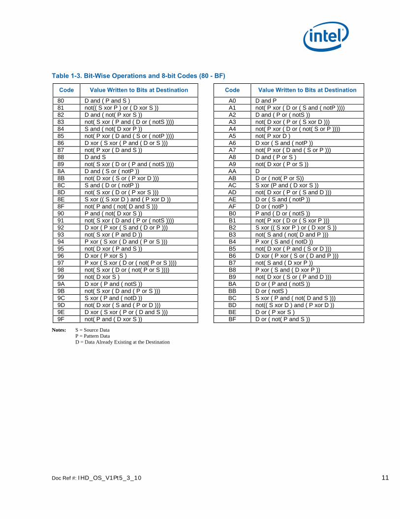
Table 1-3. Bit-Wise Operations and 8-bit Codes (80 - BF)
Code Value Written to Bits at Destination Code Value Written to Bits at Destination
80 D and ( P and S ) A0 D and P 81 not(( S xor P ) or ( D xor S )) A1 not( P xor ( D or ( S and ( notP )))) 82 D and ( not( P xor S )) A2 D and ( P or ( notS )) 83 not( S xor ( P and ( D or ( notS )))) A3 not( D xor ( P or ( S xor D ))) 84 S and ( not( D xor P )) A4 not( P xor ( D or ( not( S or P )))) 85 not( P xor ( D and ( S or ( notP )))) A5 not( P xor D ) 86 D xor ( S xor ( P and ( D or S ))) A6 D xor ( S and ( notP )) 87 not( P xor ( D and S )) A7 not( P xor ( D and ( S or P ))) 88 D and S A8 D and ( P or S ) 89 not( S xor ( D or ( P and ( notS )))) A9 not( D xor ( P or S )) 8A D and ( S or ( notP )) AA D 8B not( D xor ( S or ( P xor D ))) AB D or ( not( P or S)) 8C S and ( D or ( notP )) AC S xor (P and ( D xor S )) 8D not( S xor ( D or ( P xor S ))) AD not( D xor ( P or ( S and D ))) 8E S xor (( S xor D ) and ( P xor D )) AE D or ( S and ( notP )) 8F not( P and ( not( D and S ))) AF D or ( notP ) 90 P and ( not( D xor S )) B0 P and ( D or ( notS )) 91 not( S xor ( D and ( P or ( notS )))) B1 not( P xor ( D or ( S xor P ))) 92 D xor ( P xor ( S and ( D or P ))) B2 S xor (( S xor P ) or ( D xor S )) 93 not( S xor ( P and D )) B3 not( S and ( not( D and P ))) 94 P xor ( S xor ( D and ( P or S ))) B4 P xor ( S and ( notD )) 95 not( D xor ( P and S )) B5 not( D xor ( P and ( S or D ))) 96 D xor ( P xor S ) B6 D xor ( P xor ( S or ( D and P ))) 97 P xor ( S xor ( D or ( not( P or S )))) B7 not( S and ( D xor P )) 98 not( S xor ( D or ( not( P or S )))) B8 P xor ( S and ( D xor P )) 99 not( D xor S ) B9 not( D xor ( S or ( P and D ))) 9A D xor ( P and ( notS )) BA D or ( P and ( notS )) 9B not( S xor ( D and ( P or S ))) BB D or ( notS ) 9C S xor ( P and ( notD )) BC S xor ( P and ( not( D and S ))) 9D not( D xor ( S and ( P or D ))) BD not(( S xor D ) and ( P xor D )) 9E D xor ( S xor ( P or ( D and S ))) BE D or ( P xor S ) 9F not( P and ( D xor S )) BF D or ( not( P and S ))
Notes: S = Source Data P = Pattern Data D = Data Already Existing at the Destination

12 Doc Ref #: IHD_OS_V1Pt5_3_10
Table 1-4. Bit-Wise Operations and 8-bit Codes (C0 - FF)
Code Value Written to Bits at Destination Code Value Written to Bits at Destination
C0 P and S E0 P and ( D or S ) C1 not( S xor ( P or ( D and ( notS )))) E1 not( P xor ( D or S )) C2 not( S xor ( P or ( not( D or S )))) E2 D xor ( S and ( P xor D )) C3 not( P xor S ) E3 not( P xor ( S or ( D and P ))) C4 S and ( P or ( notD )) E4 S xor ( D and ( P xor S )) C5 not( S xor ( P or ( D xor S ))) E5 not( P xor ( D or ( S and P ))) C6 S xor ( D and ( notP )) E6 S xor ( D and ( not( P and S ))) C7 not( P xor ( S and ( D or P ))) E7 not(( S xor P ) and ( P xor D )) C8 S and ( D or P ) E8 S xor (( S xor P ) and ( D xor S )) C9 not( S xor ( P or D )) E9 not( D xor ( S xor ( P and ( not( D and S
))))) CA D xor ( P and ( S xor D )) EA D or ( P and S ) CB not( S xor ( P or ( D and S ))) EB D or ( not( P xor S )) CC S EC S or ( D and P ) CD S or ( not( D or P )) ED S or ( not( D xor P )) CE S or ( D and ( notP )) EE D or S CF S or ( notP ) EF S or ( D or ( notP )) D0 P and ( S or ( notD )) F0 P D1 not( P xor ( S or ( D xor P ))) F1 P or ( not( D or S )) D2 P xor ( D and ( notS )) F2 P or ( D and ( notS )) D3 not( S xor ( P and ( D or S ))) F3 P or ( notS ) D4 S xor (( S xor P ) and ( P xor D )) F4 P or ( S and ( notD )) D5 not( D and ( not( P and S ))) F5 P or ( notD ) D6 P xor ( S xor ( D or ( P and S ))) F6 P or ( D xor S ) D7 not( D and ( P xor S )) F7 P or ( not( D and S )) D8 P xor ( D and ( S xor P )) F8 P or ( D and S ) D9 not( S xor ( D or ( P and S ))) F9 P or ( not( D xor S )) DA D xor ( P and ( not( S and D ))) FA D or P DB not(( S xor P ) and ( D xor S )) FB D or ( P or ( notS )) DC S or ( P and ( notD )) FC P or S DD S or ( notD ) FD P or ( S or ( notD )) DE S or ( D xor P ) FE D or ( P or S ) DF S or ( not( D and P )) FF writes all 1’s
Notes: S = Source Data P = Pattern Data D = Data Already Existing at the Destination

Doc Ref #: IHD_OS_V1Pt5_3_10 13
1.2.1.4 Per-Pixel Write-Masking Operations
The BLT engine is able to perform per-pixel write-masking with various data sources used as pixel masks to constrain which pixels at the destination are to be written to by the BLT engine. As shown in the figure below, either monochrome source or monochrome pattern data may be used as pixel masks. Color pattern data cannot be used. Another available pixel mask is derived by comparing a particular color range per color channel to either the color already specified for a given pixel at the destination or source.
Figure 1-2. Block Diagram and Data Paths of the BLT Engine
128 bit ROP(8 to 1 Mux)
Src or DstTransparency
RangeComparison
128 bit Reg
Color PatternScan Line Storage32 bytes = 4 QWs
128 bit Reg
128 bit Reg
Mono SRC& Pattern
ExpansionLogic
Texture L2 Cache (128 bits)
128 bit Reg
Src/Dst (C/Z)Render Cache
Mono Source:memory based &Immediate (512 byte Max)Color Patterns:memory based &Immediate (256 byte Max = 32bpp)
128 bit Reg
128 bit Reg
128 bit Reg
128 bit Reg
128 bit Reg
DestinationRegisters
ColorSource
Registers
128 to 128 bitByte Granularity
Rotator
Almador FamilyClassical BLT
Data Path
128 bit Reg
128 bit 2 to 1Mux
Color PatternsPass thru
Expansion Logic
Color Sources,Color Patterns,
ExpandedMono Sources and
Mono Patternsare rotated through shared
Rotation Logicto the Dst alignment
128 bit Reg
Src/Dst (C/Z)Render Cache
Mono Sources andMono Patterns are
expanded to a bit per bytedepending on DST bppand rotated to the DST
alignment for transparency
The command packets can specify the monochrome source or the monochrome pattern data as a pixel mask. When this feature is used, the bits that carry a value of 0 cause the bytes of the corresponding pixel at the destination to not be written to by the BLT engine, thereby preserving whatever data was originally carried within those bytes. This feature can be used in writing characters to the display, while also preserving the pre-existing backgrounds behind those characters. When both operands are in the transparent mode, the logical AND of the 2 operands are used for the write enables per pixel.
The 3-bit field, destination transparency mode, within the command packets can select per-pixel write-masking with a mask based on the results of color comparisons. The monochrome source background and foreground are range compared with either the bytes for the pixels at the destination or the source operand. This operation is described in the BLT command packet and register descriptions.

14 Doc Ref #: IHD_OS_V1Pt5_3_10
1.2.1.5 When the Source and Destination Locations Overlap
It is possible to have BLT operations in which the locations of the source and destination data overlap. This frequently occurs in BLT operations where a user is shifting the position of a graphical item on the display by only a few pixels. In these situations, the BLT engine must be programmed so that destination data is not written into destination locations that overlap with source locations before the source data at those locations has been read. Otherwise, the source data will become corrupted. The XY commands determine whether there is an overlap and perform the accesses in the proper direction to avoid data corruption.
The following figure shows how the source data can be corrupted when a rectangular block is copied from a source location to an overlapping destination location. The BLT engine typically reads from the source location and writes to the destination location starting with the left-most pixel in the top-most line of both, as shown in step (a). As shown in step (b), corruption of the source data has already started with the copying of the top-most line in step (a) — part of the source that originally contained lighter-colored pixels has now been overwritten with darker-colored pixels. More source data corruption occurs as steps (b) through (d) are performed. At step (e), another line of the source data is read, but the two right-most pixels of this line are in the region where the source and destination locations overlap, and where the source has already been overwritten as a result of the copying of the top-most line in step (a). Starting in step (f), darker-colored pixels can be seen in the destination where lighter-colored pixels should be. This errant effect occurs repeatedly throughout the remaining steps in this BLT operation. As more lines are copied from the source location to the destination location, it becomes clear that the end result is not what was originally intended.

Doc Ref #: IHD_OS_V1Pt5_3_10 15
Figure 1-3. Source Corruption in BLT with Overlapping Source and Destination Locations
B6756-01
Source
Destination(a)
(c)
(b)
(h)
(d)
(e)
(f)
(g)
Source
Destination(i)

16 Doc Ref #: IHD_OS_V1Pt5_3_10
The BLT engine can alter the order in which source data is read and destination data is written when necessary to avoid source data corruption problems when the source and destination locations overlap. The command packets provide the ability to change the point at which the BLT engine begins reading and writing data from the upper left-hand corner (the usual starting point) to one of the other three corners. The BLT engine may be set to read data from the source and write it to the destination starting at any of the four corners of the panel.
The XY command packets perform the necessary comparisons and start at the proper corner of each operand which avoids data corruption.
Figure 1-4. Correctly Performed BLT with Overlapping Source and Destination Locations
B6757-01
Source
Destination(a)
(c)
(b)
(h)
(d)
(e)
(f)
(g)
Source
Destination(i)

Doc Ref #: IHD_OS_V1Pt5_3_10 17
The following figure illustrates how this feature of the BLT engine can be used to perform the same BLT operation as was illustrated in the figure above, while avoiding the corruption of source data. As shown in the figure below, the BLT engine reads the source data and writes the data to the destination starting with the right-most pixel of the bottom-most line. By doing this, no pixel existing where the source and destination locations overlap will ever be written to before it is read from by the BLT engine. By the time the BLT operation has reached step (e) where two pixels existing where the source and destination locations overlap are about to be over written, the source data for those two pixels has already been read.
Figure 1-5. Suggested Starting Points for Possible Source and Destination Overlap Situations
B6758-01
Source
Destination DestinationDestination
Source Source Source
Destination
OR
SourceDestination
OR
Source Destination
OR
SourceDestination Source Destination
OR
Source Source Source Source
DestinationDestination DestinationDestination
The figure above shows the recommended lines and pixels to be used as starting points in each of 8 possible ways in which the source and destination locations may overlap. In general, the starting point should be within the area in which the source and destination overlap.

18 Doc Ref #: IHD_OS_V1Pt5_3_10
1.2.2 Basic Graphics Data Considerations
1.2.2.1 Contiguous vs. Discontinuous Graphics Data
Graphics data stored in memory, particularly in the frame buffer of a graphics system, has organizational characteristics that often distinguish it from other varieties of data. The main distinctive feature is the tendency for graphics data to be organized in a discontinuous block of graphics data made up of multiple sub-blocks of bytes, instead of a single contiguous block of bytes.
Figure 1-6. Representation of On-Screen Single 6-Pixel Line in the Frame Buffer
B6761-01
(0, 479) (639, 479)
(0, 0) (639, 0)
63 32 31 0
270F8h28100h28108h
261, 256256, 256
256th Scan Line
The figure above shows an example of contiguous graphics data — a horizontal line made up of six adjacent pixels within a single scan line on a display with a resolution of 640x480. Presuming that the graphics system driving this display has been set to 8 bits per pixel and that the frame buffer’s starting address of 0h corresponds to the upper left-most pixel of this display, then the six pixels that make this horizontal line starting at coordinates (256, 256) occupies the six bytes starting at frame buffer address 28100h, and ending at address 28105h.
In this case, there is only one scan line’s worth of graphics data in this single horizontal line, so the block of graphics data for all six of these pixels exists as a single, contiguous block comprised of only these six bytes. The starting address and the number of bytes are the only pieces of information that a BLT engine would require to read this block of data.
The simplicity of the above example of a single horizontal line contrasts sharply to the example of discontinuous graphics data depicted in the figure below. The simple six-pixel line of the figure above is now accompanied by three more six-pixel lines placed on subsequent scan lines, resulting in the 6x4 block of pixels shown.

Doc Ref #: IHD_OS_V1Pt5_3_10 19
Figure 1-7. Representation of On-Screen 6x4 Array of Pixels in the Frame Buffer
B6762-01
(0, 479) (639, 479)
(0, 0) (639, 0)
63 32 31 0
270F8h28100h28108h
261, 256256, 256
256th Scan Line
270F8h28100h28108h
270F8h28100h28108h
257th Scan Line258th Scan Line259th Scan Line
Note: Drawing is not to scale
261, 259256, 259
270F8h28100h28108h
Since there are other pixels on each of the scan lines on which this 6x4 block exists that are not part of this 6x4 block, what appears to be a single 6x4 block of pixels on the display must be represented by a discontinuous block of graphics data made up of 4 separate sub-blocks of six bytes apiece in the frame buffer at addresses 28100h, 28380h, 28600h, and 28880h. This situation makes the task of reading what appears to be a simple 6x4 block of pixels more complex. However, there are two characteristics of this 6x4 block of pixels that help simplify the task of specifying the locations of all 24 bytes of this discontinuous block of graphics data: all four of the sub-blocks are of the same length, and the four sub-blocks are separated from each other at equal intervals.
The BLT engine is designed to make use of these characteristics of graphics data to simplify the programming required to handle discontinuous blocks of graphics data. For such a situation, the BLT engine requires only four pieces of information: the starting address of the first sub-block, the length of a sub-block, the offset (in bytes), pitch, of the starting address of each subsequent sub-block, and the quantity of sub-blocks.
1.2.2.2 Source Data
The source data may exist in the frame buffer or elsewhere in the graphics aperture where the BLT engine may read it directly, or it may be provided to the BLT engine by the host CPU through the command packets. The block of source graphics data may be either contiguous or discontinuous, and may be either in color (with a color depth that matches that to which the BLT engine has been set) or monochrome.
The source select bit in the command packets specifies whether the source data exists in the frame buffer or is provided through the command packets. Monochrome source data is always specified as being supplied through an immediate command packet.
If the color source data resides within the frame buffer or elsewhere in the graphics aperture, then the Source Address Register, specified in the command packets is used to specify the address of the source.

20 Doc Ref #: IHD_OS_V1Pt5_3_10
In cases where the host CPU provides the source data, it does so by writing the source data to ring buffer directly after the BLT command that requires the data or uses an IMMEDIATE_INDIRECT_BLT command packet which has a size and pointer to the operand in Graphics aperture.
The block of bytes sent by the host CPU through the command packets must be quadword-aligned and the source data contained within the block of bytes must also be aligned.
To accommodate discontinuous source data, the source and destination pitch registers can be used to specify the offset in bytes from the beginning of one scan line’s worth source data to the next. Otherwise, if the source data is contiguous, then an offset equal to the length of a scan line’s worth of source data should be specified.
1.2.2.3 Monochrome Source Data
The opcode of the command packet specifies whether the source data is color or monochrome. Since monochrome graphics data only uses one bit per pixel, each byte of monochrome source data typically carries data for 8 pixels which hinders the use of byte-oriented parameters when specifying the location and size of valid source data. Some additional parameters must be specified to ensure the proper reading and use of monochrome source data by the BLT engine. The BLT engine also provides additional options for the manipulation of monochrome source data versus color source data.
The various bit-wise logical operations and per-pixel write-masking operations were designed to work with color data. In order to use monochrome data, the BLT engine converts it into color through a process called color expansion, which takes place as a BLT operation is performed. In color expansion the single bits of monochrome source data are converted into one, two, or four bytes (depending on the color depth) of color data that are set to carry value corresponding to either the foreground or background color that have been specified for use in this conversion process. If a given bit of monochrome source data carries a value of 1, then the byte(s) of color data resulting from the conversion process will be set to carry the value of the foreground color. If a given bit of monochrome source data carries a value of 0, then the resulting byte(s) will be set to the value of the background color. The foreground and background colors used in the color expansion of monochrome source data can be set in the source expansion foreground color register and the source expansion background color register.
The BLT Engine requires that the bit alignment of each scan line’s worth of monochrome source data be specified. Each scan line’s worth of monochrome source data is word aligned but can actually start on any bit boundary of the first byte. Monochrome text is special cased and it is bit or byte packed, where in bit packed there are no invalid pixels (bits) between scan lines. There is a 3 bit field which indicates the starting pixel position within the first byte for each scan line, Mono Source Start.
The BLT engine also provides various clipping options for use with specific BLT commands (BLT_TEXT) with a monochrome source. Clipping is supported through: Clip rectangle Y addresses or coordinates and X coordinates along with scan line starting and ending addresses (with Y addresses) along with X starting and ending coordinates.
The maximum immediate source size is 128 bytes.
1.2.2.4 Pattern Data
The color pattern data must exist within the frame buffer or Graphics aperture where the BLT engine may read it directly or it can be sent through the command stream. The pattern data must be located in linear memory. Monochrome pattern data is supplied by the command packet when it is to be used. As shown in figure below, the block of pattern graphics data always represents a block of 8x8 pixels. The bits or bytes of a block of pattern data may be organized in the frame buffer memory in only one of three ways, depending upon its color depth which may be 8, 16, or 32 bits per pixel (whichever matches the color depth to which the BLT engine has been set), or monochrome.
The maximum color pattern size is 256 bytes.

Doc Ref #: IHD_OS_V1Pt5_3_10 21
Figure 1-8. Pattern Data -- Always an 8x8 Array of Pixels
B6763-01
63 57 56
Pixel (7, 7)Pixel (0, 7)
Pixel (0, 0)
Pixel(0, 0)
Pixel(7, 0)
Pixel(0, 7)
Pixel(7, 7)
Pixel (7, 0)
48 47 40 39 32 31 24 23 16 15 8 7 0
The Pattern Address Register is used to specify the address of the color pattern data at which the block of pattern data begins. The three least significant bits of the address written to this register are ignored, because the address must be in terms of quadwords. This is because the pattern must always be located on an address boundary equal to its size. Monochrome patterns take up 8 bytes, or a single quadword of space, and are loaded through the command packet that uses it. Similarly, color patterns with color depths of 8, 16, and 32 bits per pixel must start on 64-byte, 128-byte and 256-byte boundaries, respectively. The next 3 figures show how monochrome, 8bpp, 16bpp, and 32bpp pattern data , respectively, is organized in memory.
Figure 1-9. 8bpp Pattern Data -- Occupies 64 Bytes (8 quadwords)
B6764-01
063 57 56 48 47 40 39 24 2332 31 16 15 8 7
Pixel (0, 7) Pixel (0, 0)
Pixel (7, 7) Pixel (7, 0)
00h
28h
08h
10h
18h
20h
30h
38h
22 Doc Ref #: IHD_OS_V1Pt5_3_10
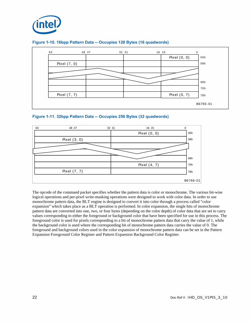
Figure 1-10. 16bpp Pattern Data -- Occupies 128 Bytes (16 quadwords)
B6765-01
063 48 47 32 31 16 15
Pixel (0, 0)
Pixel (7, 0)
Pixel (7, 7)
00h
70h
08h
68h
78hPixel (0, 7)
Figure 1-11. 32bpp Pattern Data -- Occupies 256 Bytes (32 quadwords)
B6766-01
063 48 47 32 31 16 15
Pixel (0, 0)
Pixel (3, 0)
Pixel (7, 7)
00h
70h
08h
68h
78h
Pixel (4, 7)
The opcode of the command packet specifies whether the pattern data is color or monochrome. The various bit-wise logical operations and per-pixel write-masking operations were designed to work with color data. In order to use monochrome pattern data, the BLT engine is designed to convert it into color through a process called “color expansion” which takes place as a BLT operation is performed. In color expansion, the single bits of monochrome pattern data are converted into one, two, or four bytes (depending on the color depth) of color data that are set to carry values corresponding to either the foreground or background color that have been specified for use in this process. The foreground color is used for pixels corresponding to a bit of monochrome pattern data that carry the value of 1, while the background color is used where the corresponding bit of monochrome pattern data carries the value of 0. The foreground and background colors used in the color expansion of monochrome pattern data can be set in the Pattern Expansion Foreground Color Register and Pattern Expansion Background Color Register.

Doc Ref #: IHD_OS_V1Pt5_3_10 23
1.2.2.5 Destination Data
There are actually two different types of “destination data”: the graphics data already residing at the location that is designated as the destination, and the data that is to be written into that very same location as a result of a BLT operation.
The location designated as the destination must be within the frame buffer or Graphics aperture where the BLT engine can read from it and write to it directly. The blocks of destination data to be read from and written to the destination may be either contiguous or discontinuous. All data written to the destination will have the color depth to which the BLT engine has been set. It is presumed that any data already existing at the destination which will be read by the BLT engine will also be of this same color depth — the BLT engine neither reads nor writes monochrome destination data.
The Destination Address Register is used to specify the address of the destination.
To accommodate discontinuous destination data, the Source and Destination Pitch Registers can be used to specify the offset in bytes from the beginning of one scan line’s worth of destination data to the next. Otherwise, if the destination data is contiguous, then an offset equal to the length of a scan line’s worth of destination data should be specified.
1.2.3 BLT Programming Examples
1.2.3.1 Pattern Fill — A Very Simple BLT
In this example, a rectangular area on the screen is to be filled with a color pattern stored as pattern data in off-screen memory. The screen has a resolution of 1024x768 and the graphics system has been set to a color depth of 8 bits per pixel.
24 Doc Ref #: IHD_OS_V1Pt5_3_10
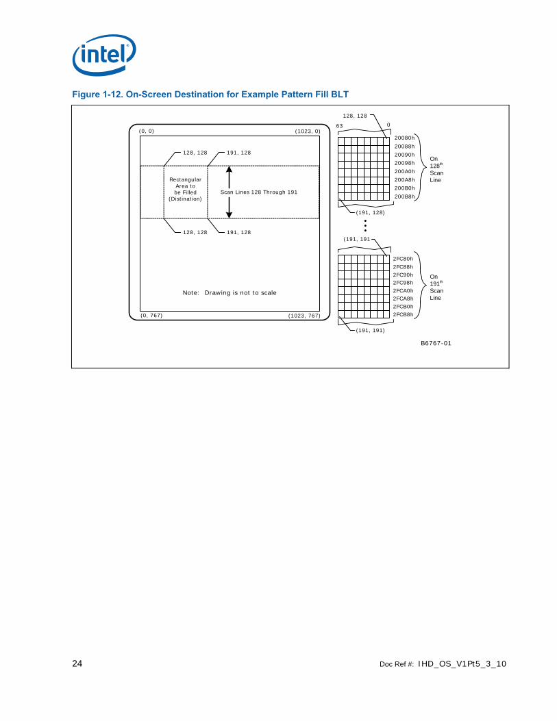
Figure 1-12. On-Screen Destination for Example Pattern Fill BLT
B6767-01
On 128th
Scan Line
20080h
20088h
20090h
20098h
200A0h
200A8h
200B0h
200B8h
(191, 128)
63 0
128, 128
On 191th
Scan Line
2FC80h
2FC88h2FC90h2FC98h2FCA0h2FCA8h2FCB0h2FCB8h
(191, 191)
(191, 191
(0, 767) (1023, 767)
(0, 0) (1023, 0)
Note: Drawing is not to scale
RectangularArea tobe Filled
(Distination)
128, 128 191, 128
128, 128 191, 128
Scan Lines 128 Through 191

Doc Ref #: IHD_OS_V1Pt5_3_10 25
As shown in the figure above, the rectangular area to be filled has its upper left-hand corner at coordinates (128, 128) and its lower right-hand corner at coordinates (191, 191). These coordinates define a rectangle covering 64 scan lines, each scan line’s worth of which is 64 pixels in length — in other words, an array of 64x64 pixels. Presuming that the pixel at coordinates (0, 0) corresponds to the byte at address 00h in the frame buffer memory, the pixel at (128, 128) corresponds to the byte at address 20080h.
Figure 1-13. Pattern Data for Example Pattern Fill BLT
B6768-01
63 0
100000h100008h100010h100018h100020h100028h100030h100038h
(0, 0)
(0, 7)
(7, 0)
(7, 7)
Pattern Data(0, 0)(7, 0)
(0, 7)(7, 7)
As shown in figure above, the pattern data occupies 64 bytes starting at address 100000h. As always, the pattern data represents an 8x8 array of pixels.
The BLT command packet is used to select the features to be used in this BLT operation, and must be programmed carefully. The vertical alignment field should be set to 0 to select the top-most horizontal row of the pattern as the starting row used in drawing the pattern starting with the top-most scan line covered by the destination. The pattern data is in color with a color depth of 8 bits per pixel, so the dynamic color enable should be asserted with the dynamic color depth field should be set to 0. Since this BLT operation does not use per-pixel write-masking (destination transparency mode), this field should be set to 0. Finally, the raster operation field should be programmed with the 8-bit value of F0h to select the bit-wise logical operation in which a simple copy of the pattern data to the destination takes place. Selecting this bit-wise operation in which no source data is used as an input causes the BLT engine to automatically forego either reading source data from the frame buffer.
The Destination Pitch Register must be programmed with number of bytes in the interval from the start of one scan line’s worth of destination data to the next. Since the color depth is 8 bits per pixel and the horizontal resolution of the display is 1024, the value to be programmed into these bits is 400h, which is equal to the decimal value of 1024.
Bits [31:3] of the Pattern Address Register must be programmed with the address of the pattern data.
Similarly, bits [31:0] of the Destination Address Register must be programmed with the byte address at the destination that will be written to first. In this case, the address is 20080h, which corresponds to the byte representing the pixel at coordinates (128, 128).
This BLT operation does not use the values in the Source Address Register or the Source Expansion Background or Foreground Color Registers.
26 Doc Ref #: IHD_OS_V1Pt5_3_10
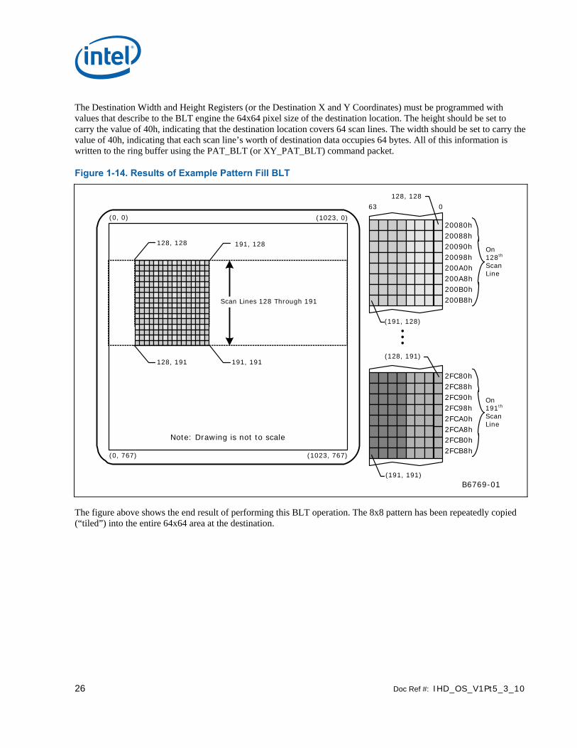
The Destination Width and Height Registers (or the Destination X and Y Coordinates) must be programmed with values that describe to the BLT engine the 64x64 pixel size of the destination location. The height should be set to carry the value of 40h, indicating that the destination location covers 64 scan lines. The width should be set to carry the value of 40h, indicating that each scan line’s worth of destination data occupies 64 bytes. All of this information is written to the ring buffer using the PAT_BLT (or XY_PAT_BLT) command packet.
Figure 1-14. Results of Example Pattern Fill BLT
B6769-01
Note: Drawing is not to scale
63 0
20080h20088h20090h20098h200A0h200A8h200B0h200B8h
On 128th
Scan Line
(191, 128)
(128, 191)
2FC80h2FC88h2FC90h2FC98h2FCA0h2FCA8h2FCB0h2FCB8h
(191, 191)
128, 128
On 191th
Scan Line
2FC80h2FC88h2FC90h2FC98h2FCA0h2FCA8h2FCB0h2FCB8h
(0, 767) (1023, 767)
(0, 0) (1023, 0)
128, 191 191, 191
Scan Lines 128 Through 191
128, 128 191, 128
The figure above shows the end result of performing this BLT operation. The 8x8 pattern has been repeatedly copied (“tiled”) into the entire 64x64 area at the destination.

Doc Ref #: IHD_OS_V1Pt5_3_10 27
1.2.3.2 Drawing Characters Using a Font Stored in System Memory
In this example BLT operation, a lowercase letter “f” is to be drawn in black on a display with a gray background. The resolution of the display is 1024x768, and the graphics system has been set to a color depth of 8 bits per pixel.
Figure 1-15. On-Screen Destination for Example Character Drawing BLT
B6770-01
Note: Drawing is not to scale
(0, 767) (1023, 767)
(0, 0) (1023, 0)
128, 191
Scan Lines 128 Through 135
128, 128
128, 128
63 0
128, 128
20080h(128th Scan Line)
20480h
20880h
20C80h
21080h
21480h
21880h
21C80h
135, 135135, 135
(129th Scan Line)
(130th Scan Line)
(131th Scan Line)
(132nd Scan Line)
(133rd Scan Line)
(134th Scan Line)
(135th Scan Line)
Destination
The figure above shows the display on which this letter “f” is to be drawn. As shown in this figure, the entire display has been filled with a gray color. The letter “f” is to be drawn into an 8x8 region on the display with the upper left-hand corner at the coordinates (128, 128).
Figure 1-16. Source Data in System Memory for Example Character Drawing BLT
B6771-01
Pixel (0, 0)
Pixel (7, 7)
063 57
00000000 00010000 00010000 00111100 00010000 00010000 00001100 00000000
(0, 7)(7, 7) (7, 0)
(0, 0)
Source Data
56 4847 40 39 32 31 24 23 16 15 8 7
Pixel (0, 7)
Pixel (7, 0)
The figure above shows both the 8x8 pattern making up the letter “f” and how it is represented somewhere in the host’s system memory — the actual address in system memory is not important. The letter “f” is represented in system memory by a block of monochrome graphics data that occupies 8 bytes. Each byte carries the 8 bits needed to represent the 8 pixels in each scan line’s worth of this graphics data. This type of pattern is often used to store character fonts in system memory.
28 Doc Ref #: IHD_OS_V1Pt5_3_10
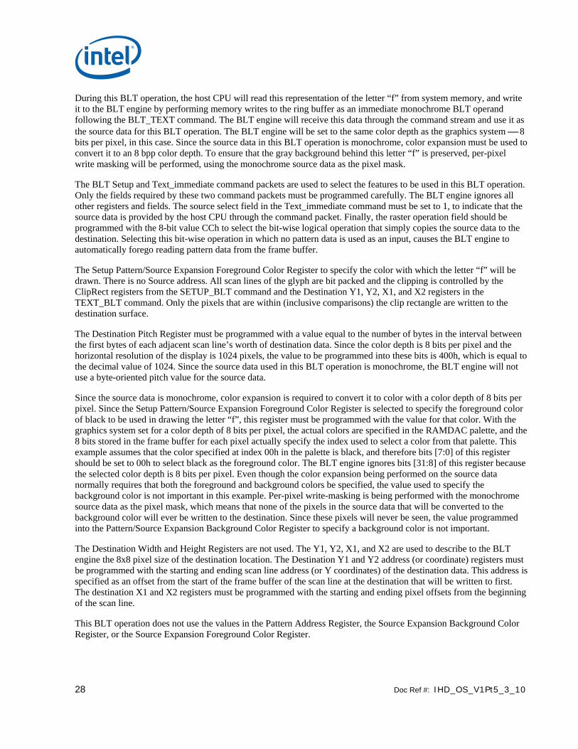
During this BLT operation, the host CPU will read this representation of the letter “f” from system memory, and write it to the BLT engine by performing memory writes to the ring buffer as an immediate monochrome BLT operand following the BLT_TEXT command. The BLT engine will receive this data through the command stream and use it as the source data for this BLT operation. The BLT engine will be set to the same color depth as the graphics system ⎯ 8 bits per pixel, in this case. Since the source data in this BLT operation is monochrome, color expansion must be used to convert it to an 8 bpp color depth. To ensure that the gray background behind this letter “f” is preserved, per-pixel write masking will be performed, using the monochrome source data as the pixel mask.
The BLT Setup and Text_immediate command packets are used to select the features to be used in this BLT operation. Only the fields required by these two command packets must be programmed carefully. The BLT engine ignores all other registers and fields. The source select field in the Text_immediate command must be set to 1, to indicate that the source data is provided by the host CPU through the command packet. Finally, the raster operation field should be programmed with the 8-bit value CCh to select the bit-wise logical operation that simply copies the source data to the destination. Selecting this bit-wise operation in which no pattern data is used as an input, causes the BLT engine to automatically forego reading pattern data from the frame buffer.
The Setup Pattern/Source Expansion Foreground Color Register to specify the color with which the letter “f” will be drawn. There is no Source address. All scan lines of the glyph are bit packed and the clipping is controlled by the ClipRect registers from the SETUP_BLT command and the Destination Y1, Y2, X1, and X2 registers in the TEXT_BLT command. Only the pixels that are within (inclusive comparisons) the clip rectangle are written to the destination surface.
The Destination Pitch Register must be programmed with a value equal to the number of bytes in the interval between the first bytes of each adjacent scan line’s worth of destination data. Since the color depth is 8 bits per pixel and the horizontal resolution of the display is 1024 pixels, the value to be programmed into these bits is 400h, which is equal to the decimal value of 1024. Since the source data used in this BLT operation is monochrome, the BLT engine will not use a byte-oriented pitch value for the source data.
Since the source data is monochrome, color expansion is required to convert it to color with a color depth of 8 bits per pixel. Since the Setup Pattern/Source Expansion Foreground Color Register is selected to specify the foreground color of black to be used in drawing the letter “f”, this register must be programmed with the value for that color. With the graphics system set for a color depth of 8 bits per pixel, the actual colors are specified in the RAMDAC palette, and the 8 bits stored in the frame buffer for each pixel actually specify the index used to select a color from that palette. This example assumes that the color specified at index 00h in the palette is black, and therefore bits [7:0] of this register should be set to 00h to select black as the foreground color. The BLT engine ignores bits [31:8] of this register because the selected color depth is 8 bits per pixel. Even though the color expansion being performed on the source data normally requires that both the foreground and background colors be specified, the value used to specify the background color is not important in this example. Per-pixel write-masking is being performed with the monochrome source data as the pixel mask, which means that none of the pixels in the source data that will be converted to the background color will ever be written to the destination. Since these pixels will never be seen, the value programmed into the Pattern/Source Expansion Background Color Register to specify a background color is not important.
The Destination Width and Height Registers are not used. The Y1, Y2, X1, and X2 are used to describe to the BLT engine the 8x8 pixel size of the destination location. The Destination Y1 and Y2 address (or coordinate) registers must be programmed with the starting and ending scan line address (or Y coordinates) of the destination data. This address is specified as an offset from the start of the frame buffer of the scan line at the destination that will be written to first. The destination X1 and X2 registers must be programmed with the starting and ending pixel offsets from the beginning of the scan line.
This BLT operation does not use the values in the Pattern Address Register, the Source Expansion Background Color Register, or the Source Expansion Foreground Color Register.

Doc Ref #: IHD_OS_V1Pt5_3_10 29
Figure 1-17. Results of Example Character Drawing BLT
B6772-01
Note: Drawing is not to scale
(0, 767) (1023, 767)
(0, 0) (1023, 0)
128, 191
Scan Lines 128 Through 135
128, 128
128, 128
63 0
128, 128
20080h(128th Scan Line)
20480h
20880h
20C80h
21080h
21480h
21880h
21C80h
135, 135135, 135
(129th Scan Line)
(130th Scan Line)
(131th Scan Line)
(132nd Scan Line)
(133rd Scan Line)
(134th Scan Line)
(135th Scan Line)
Destination
The preceding shows the end result of performing this BLT operation. Only the pixels that form part of the actual letter “f” have been drawn into the 8x8 destination location on the display, leaving the other pixels within the destination with their original gray color.
1.3 BLT Instruction Overview
This chapter defines the instructions used to control the 2D (BLT) rendering function.
The instructions detailed in this chapter are used across devices. However, slight changes may be present in some instructions (i.e., for features added or removed), or some instructions may be removed entirely. Refer to the Device Dependencies chapter for summary information regarding device-specific behaviors/interfaces/features.
The XY instructions offload the drivers by providing X and Y coordinates and taking care of the access directions for overlapping BLTs without fields specified by the driver.
Color pixel sizes supported are 8, 16, and 32 bits per pixel (bpp). All pixels are naturally aligned.
30 Doc Ref #: IHD_OS_V1Pt5_3_10
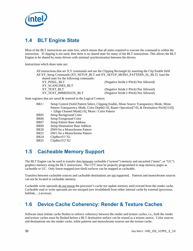
1.4 BLT Engine State
Most of the BLT instructions are state-free, which means that all states required to execute the command is within the instruction. If clipping is not used, then there is no shared state for many of the BLT instructions. This allows the BLT Engine to be shared by many drivers with minimal synchronization between the drivers.
Instructions which share state are:
All instructions that are X,Y commands and use the Clipping Rectangle by asserting the Clip Enable field All XY_Setup Commands (XY_SETUP_BLT and XY_SETUP_MONO_PATTERN_SL_BLT) load the
shared state for the following commands: XY_PIXEL_BLT (Negative Stride (=Pitch) Not Allowed) XY_SCANLINES_BLT XY_TEXT_BLT (Negative Stride (=Pitch) Not Allowed) XY_TEXT_IMMEDIATE_BLT (Negative Stride (=Pitch) Not Allowed)
State registers that are saved & restored in the Logical Context:
BR1+ Setup Control (Solid Pattern Select, Clipping Enable, Mono Source Transparency Mode, Mono Pattern Transparency Mode, Color Depth[1:0], Raster Operation[7:0], & Destination Pitch[15:0]) + 32bpp Channel Mask[1:0], Mono / Color Pattern
BR05 Setup Background Color BR06 Setup Foreground Color BR07 Setup Pattern Base Address BR09 Setup Destination Base Address BR20 DW0 for a Monochrome Pattern BR21 DW1 for a Monochrome Pattern BR24 ClipRectY1’X1 BR25 ClipRectY2’X2
1.5 Cacheable Memory Support
The BLT Engine can be used to transfer data between cacheable (“system”) memory and uncached (“main”, or “UC”) graphics memory using the BLT instructions. The GTT must be properly programmed to map memory pages as cacheable or UC. Only linear-mapped (not tiled) surfaces can be mapped as cacheable.
Transfers between cacheable sources and cacheable destinations are not supported. Patterns and monochrome sources can not be located in cacheable memory.
Cacheable write operands do not snoop the processor’s cache nor update memory until evicted from the render cache. Cacheable read or write operands are not snooped (nor invalidated) from either internal cache by external (processor, hublink,…) accesses.
1.6 Device Cache Coherency: Render & Texture Caches
Software must initiate cache flushes to enforce coherency between the render and texture caches, i.e., both the render and texture caches must be flushed before a BLT destination surface can be reused as a texture source. Color sources and destinations use the render cache, while patterns and monochrome sources use the texture cache.

Doc Ref #: IHD_OS_V1Pt5_3_10 31
1.7 BLT Engine Instructions
The Instruction Target field is used as an opcode by the BLT Engine state machine to qualify the control bits that are relevant for executing the instruction. The descriptions for each DWord and bit field are contained in the BLT Engine Instruction Field Definition section. Each DWord field is described as a register, but none of these registers can be written of read through a memory mapped location – they are internal state only.
1.7.1 Blt Programming Restrictions
Overlapping Source/Destination BLTs: The following condition must be avoided when programming the Blt engine: Linear surfaces with a cache line in scan line Y for the source stream overlapping with a cache line in scan line Y-1 for the dest stream (=> non-aligned surface pitches). The cache coherency rules combined with the Blitter data consumption rules result in UNDEFINED operation. (Note that this restriction will likely follow forward to future products due to architectural complexities.) There are two suggested software workarounds:
In order to perform coherent overlapping Blts, (a) the Source and Destination Base Address registers must hold the same value (without alignment restriction), and (b) the Source and Destination Pitch registers (BR11,BR13) must both be a multiple of 64 bytes.
If (a) isn’t possible, do overlapping source copy BLTs as two blits, using a separate intermediate surface.
All reserved fields must be programmed to 0s.
When using monosource or text data (bit/byte/word aligned): do not program pixel widths greater than 32,745 pixels.
Ring Buffer Programming[Dev ILK]: Driver should make sure the first 3D command after the engine switch from BLT not to be
1. DrawCall. 2. Curbe 3. Media Object.
The other way to do this is driver should always program a dummy 3D
NON-PIPELINE state following the BLT commands.

32 Doc Ref #: IHD_OS_V1Pt5_3_10
1.8 Fill/Move Instructions
These instructions use linear addresses with width and height. BLT clipping is not supported.
1.8.1 COLOR_BLT (Fill)
COLOR_BLT is the simplest BLT operation. It performs a color fill to the destination (with a possible ROP). The only operand is the destination operand which is written dependent on the raster operation. The solid pattern color is stored in the pattern background register.
This instruction is optimized to run at the maximum memory write bandwidth.
The typical Raster operation code = F0 which performs a copy of the pattern background register to the destination.
DWord Bit Description
0 = BR00 31:29 Client: 02h - 2D Processor
28:22 Instruction Target (Opcode) : 40h
21:20 32 bpp byte mask: (21 =1= write alpha channel; 20=1= write RGB channels)
19:05 Reserved. Note no tiling specification allowed for this non-XY blit command. Only linear blits are allowed.
04:00 DWord Length: 03h
1 = BR13 31:26 Reserved.
25:24 Color Depth: 00 = 8 bit color. 01 = 16 bit color (656). 10 = 16 bit color (1555). 11 = 32 bit color
23:16 Raster Operation:
15:00 Destination Pitch (signed): Destination pitch in bytes (Same as before).
2 = BR14 31:16 Destination Height (in scan lines):
15:00 Destination Width (in bytes):
3 = BR09 31:00 Destination Address: Address of the first byte to be written
4 = BR16 31:00 Solid Pattern Color: 8 bit = [7:0], 16 bit = [15:0], 32 bit = [31:0]

Doc Ref #: IHD_OS_V1Pt5_3_10 33
1.8.2 SRC_COPY_BLT (Move)
This BLT instruction performs a color source copy where the only operands involved is a color source and destination of the same bit width.
The source and destination operands may overlap. The command must indicate the horizontal and vertical directions: either forward or backwards to avoid data corruption. The X direction (horizontal) field applies to both the destination and source operands. The source and destination pitches (stride) are signed.
DWord Bit Description
0 = BR00 31:29 Client: 02h – 2D Processor
28:22 Instruction Target (Opcode) : 43h
21:20 32 bpp byte mask: (21 =1= write alpha channel; 20=1= write RGB channels)
19:05 Reserved. Note no tiling specification allowed for this non-XY blit command. Only linear blits are allowed.
04:00 Dword Length: 04h
1 = BR13 31 Reserved.
30 X Direction (1 = written from right to left (decrementing = backwards); 0 = incrementing)
29:26 Reserved.
25:24 Color Depth: 00 = 8 bit color 01 = 16 bit color (565) 10 = 16 bit color (1555) 11 = 32 bit color
23:16 Raster Operation:
15:00 Destination Pitch (signed): Destination pitch in bytes (Same as before).
2 = BR14 31:16 Destination Height (in scan lines):
15:00 Destination Width (in bytes):
3 = BR09 31:00 Destination Address: Address of the first byte to be written
31:14 Reserved.
4 = BR11 15:00 Source Pitch: (double word aligned and signed)
5 = BR12 31:00 Source Address: Address of the first byte to be read.

34 Doc Ref #: IHD_OS_V1Pt5_3_10
1.9 2D (X,Y) BLT Instructions
Most BLT instructions (prefixed with “XY_”) use 2D X,Y coordinate specifications vs. lower-level linear addresses. These instructions also support simple 2D clipping against a clip rectangle.
The top and left Clipping coordinates are inclusive. The bottom and right coordinates are exclusive. The BLT Engine performs a trivial reject for all CLIP BLT instructions before performing any accesses.
Negative destination and source coordinates are supported. In the case of negative source coordinates, the destination X1 and Y1 are modified by the absolute value of the negative source coordinate before the destination clip checking and final drawing coordinates are calculated. The absolute value of the source negative coordinate is added to the corresponding destination coordinate. The BLT engine clipping also checks for (DX2 [ or = DX1) or (DY2 [ or = DY1) after this calculation and if true, then the BLT is totally rejected.
B6773-01
D(X1 Y1)
C(X2 Y2)
DBA(DX=0,DY=0)SRA
(SX=0,SY=0)
S(X1 Y1)
Dest. PitchSource Pitch
Source SurfaceDestination Surface
Some Equalities & Inequalities for Source Clipping:
Src. TD = Dst. TD (Top discard in SL)Src LD = LD (Left Discard in Pixels)Src Height = Dst. Height in SLSrc Width = Dst. Width in Pixels
Note: Src. Pitch is not equal to Dst. Pitch
Src
. TD
Src. LD Src. Width
Src
. H
eig
ht
Lower SL
Upper SLC(X1 Y1)
Dst. WidthLDD
st.
TD
Dst
. H
eig
ht
D(X2 Y2)
Left Pixel
Right Pixel
DX1, DY1, CX1, and CY1 are inclusive, while DX2, DY2, CX2, and CY2 are exclusive.
Doc Ref #: IHD_OS_V1Pt5_3_10 35
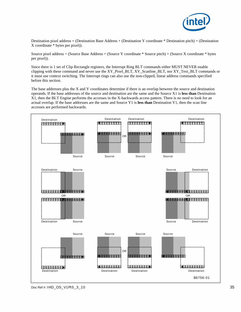
Destination pixel address = (Destination Base Address + (Destination Y coordinate * Destination pitch) + (Destination X coordinate * bytes per pixel)).
Source pixel address = (Source Base Address + (Source Y coordinate * Source pitch) + (Source X coordinate * bytes per pixel)).
Since there is 1 set of Clip Rectangle registers, the Interrupt Ring BLT commands either MUST NEVER enable clipping with these command and never use the XY_Pixel_BLT, XY_Scanline_BLT, nor XY_Text_BLT commands or it must use context switching. The Interrupt rings can also use the non-clipped, linear address commands specified before this section.
The base addresses plus the X and Y coordinates determine if there is an overlap between the source and destination operands. If the base addresses of the source and destination are the same and the Source X1 is less than Destination X1, then the BLT Engine performs the accesses in the X-backwards access pattern. There is no need to look for an actual overlap. If the base addresses are the same and Source Y1 is less than Destination Y1, then the scan line accesses are performed backwards.
B6758-01
Source
Destination DestinationDestination
Source Source Source
Destination
OR
SourceDestination
OR
Source Destination
OR
SourceDestination Source Destination
OR
Source Source Source Source
DestinationDestination DestinationDestination
36 Doc Ref #: IHD_OS_V1Pt5_3_10
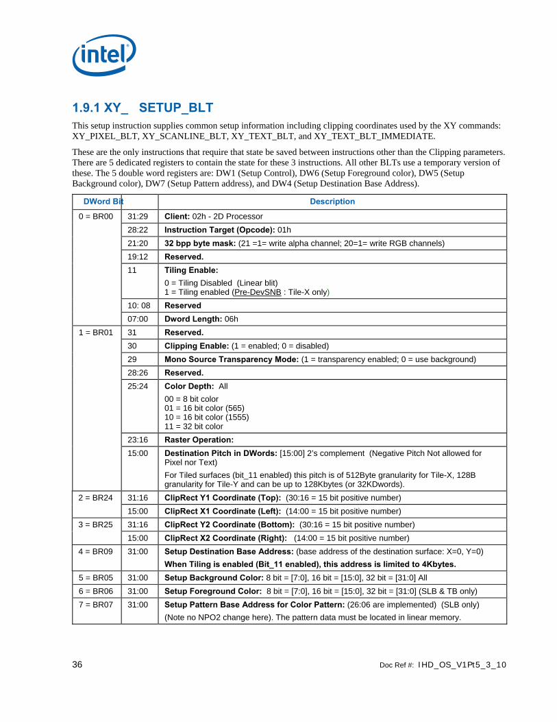
1.9.1 XY_ SETUP_BLT This setup instruction supplies common setup information including clipping coordinates used by the XY commands: XY_PIXEL_BLT, XY_SCANLINE_BLT, XY_TEXT_BLT, and XY_TEXT_BLT_IMMEDIATE.
These are the only instructions that require that state be saved between instructions other than the Clipping parameters. There are 5 dedicated registers to contain the state for these 3 instructions. All other BLTs use a temporary version of these. The 5 double word registers are: DW1 (Setup Control), DW6 (Setup Foreground color), DW5 (Setup Background color), DW7 (Setup Pattern address), and DW4 (Setup Destination Base Address).
DWord Bit Description
0 = BR00 31:29 Client: 02h - 2D Processor 28:22 Instruction Target (Opcode): 01h 21:20 32 bpp byte mask: (21 =1= write alpha channel; 20=1= write RGB channels) 19:12 Reserved. 11 Tiling Enable:
0 = Tiling Disabled (Linear blit) 1 = Tiling enabled (Pre-DevSNB : Tile-X only)
10: 08 Reserved 07:00 Dword Length: 06h 1 = BR01 31 Reserved. 30 Clipping Enable: (1 = enabled; 0 = disabled) 29 Mono Source Transparency Mode: (1 = transparency enabled; 0 = use background) 28:26 Reserved. 25:24 Color Depth: All
00 = 8 bit color 01 = 16 bit color (565) 10 = 16 bit color (1555) 11 = 32 bit color
23:16 Raster Operation: 15:00 Destination Pitch in DWords: [15:00] 2’s complement (Negative Pitch Not allowed for
Pixel nor Text) For Tiled surfaces (bit_11 enabled) this pitch is of 512Byte granularity for Tile-X, 128B granularity for Tile-Y and can be up to 128Kbytes (or 32KDwords).
2 = BR24 31:16 ClipRect Y1 Coordinate (Top): (30:16 = 15 bit positive number) 15:00 ClipRect X1 Coordinate (Left): (14:00 = 15 bit positive number) 3 = BR25 31:16 ClipRect Y2 Coordinate (Bottom): (30:16 = 15 bit positive number) 15:00 ClipRect X2 Coordinate (Right): (14:00 = 15 bit positive number) 4 = BR09 31:00 Setup Destination Base Address: (base address of the destination surface: X=0, Y=0)
When Tiling is enabled (Bit_11 enabled), this address is limited to 4Kbytes. 5 = BR05 31:00 Setup Background Color: 8 bit = [7:0], 16 bit = [15:0], 32 bit = [31:0] All 6 = BR06 31:00 Setup Foreground Color: 8 bit = [7:0], 16 bit = [15:0], 32 bit = [31:0] (SLB & TB only) 7 = BR07 31:00 Setup Pattern Base Address for Color Pattern: (26:06 are implemented) (SLB only)
(Note no NPO2 change here). The pattern data must be located in linear memory.

Doc Ref #: IHD_OS_V1Pt5_3_10 37
1.9.2 XY_SETUP_MONO_PATTERN_SL_BLT This setup instruction supplies common setup information including clipping coordinates used exclusively with the following instruction: XY_SCANLINE_BLT (SLB) - 1 scan line of monochrome pattern and destination are the only operands allowed.
DWord Bit Description
0 = BR00 31:29 Client: 02h - 2D Processor 28:22 Instruction Target (Opcode): 11h 21:20 32 bpp byte mask: (21 =1= write alpha channel; 20=1= write RGB channels) 19:12 Reserved. 11 Tiling Enable:
0 = Tiling Disabled (Linear blit) 1 = Tiling enabled (Pre-DevSNB : Tile-X only.)
10: 08 Reserved 07:00 Dword Length: 07h 1 = BR01 31 Solid Pattern Select: (1 = solid pattern; 0 = no solid pattern) - (SLB & Pixel only) 30 Clipping Enable: (1 = enabled; 0 = disabled) 29 Reserved. 28 Mono Pattern Transparency Mode: (1 = transparency enabled; 0 = use background) 27:26 Reserved. 25:24 Color Depth:
00 = 8 bit color 01 = 16 bit color (565) 10 = 16 bit color (1555) 11 = 32 bit color
23:16 Raster Operation: 15:00 Destination Pitch in DWords: [15:00] 2’s complement (Negative Pitch Not allowed for
Pixel nor Text) For Tiled surfaces (bit_11 enabled) this pitch is of 512Byte granularity for Tile-X, 128B granularity for Tile-Y and can be up to 128Kbytes (or 32KDwords).
2 = BR24 31:16 ClipRect Y1 Coordinate (Top): (30:16 = 15 bit positive number) 15:00 ClipRect X1 Coordinate (Left): (14:00 = 15 bit positive number) 3 = BR25 31:16 ClipRect Y2 Coordinate (Bottom): (30:16 = 15 bit positive number) 15:00 ClipRect X2 Coordinate (Right): (14:00 = 15 bit positive number) 4 = BR09 31:00 Setup Destination Base Address: (base address of the destination surface: X=0, Y=0)
When Tiling is enabled (Bit_11 enabled), this address is limited to 4Kbytes. 5 = BR05 31:00 Setup Background Color: 8 bit = [7:0], 16 bit = [15:0], 32 bit = [31:0] 6 = BR06 31:00 Setup Foreground Color: 8 bit = [7:0], 16 bit = [15:0], 32 bit = [31:0] 7 = BR20 31:00 DW0 (least significant) for a Monochrome Pattern: 8 = BR21 31:00 DW1 (most significant) for a Monochrome Pattern:

38 Doc Ref #: IHD_OS_V1Pt5_3_10
1.9.3 XY_ SETUP_CLIP_ BLT This command is used to only change the clip coordinate registers. These are the same clipping registers as the Setup clipping registers above.
DWord Bit Description
0 = BR00 31:29 Client: 02h - 2D Processor 28:22 Instruction Target (Opcode): 03h 21:12 Reserved. 11 Tiling Enable:
0 = Tiling Disabled (Linear blit) 1 = Tiling enabled (Pre-DevSNB : Tile-X only)
10: 08 Reserved 07:00 Dword Length: 01h 1 = BR24 31:16 ClipRect Y1 Coordinate (Top): (30:16 = 15 bit positive number) 15:00 ClipRect X1 Coordinate (Left): (14:00 = 15 bit positive number) 2 = BR25 31:16 ClipRect Y2 Coordinate (Bottom): (30:16 = 15 bit positive number) 15:00 ClipRect X2 Coordinate (Right): (14:00 = 15 bit positive number)
1.9.4 XY_PIXEL_BLT
The Destination X coordinate and Destination Y coordinate is compared with the ClipRect registers. If it is within all 4 comparisons, then the pixel supplied in the XY_SETUP_BLT instruction is written with the raster operation to (Destination Y Address + (Destination Y coordinate * Destination pitch) + (Destination X coordinate * bytes per pixel)).
ROP field must specify pattern or fill with 0’s or 1’s. There is no source operand.
Negative Stride (= Pitch) specified in the Setup command is Not Allowed
DWord Bit Description
0 = BR00 31:29 Client: 02h - 2D Processor 28:22 Instruction Target (Opcode): 24h 21:12 Reserved. 11 Tiling Enable:
0 = Tiling Disabled (Linear blit) 1 = Tiling enabled (Pre-DevSNB : Tile-X only.)
10: 08 Reserved 07:00 Dword Length : 00h 1 = BR22 31:16 Destination Y1 Coordinate (Top): (31:16 = 16 bit signed number) 15:00 Destination X1 Coordinate (Left): (15:00 = 16 bit signed number)

Doc Ref #: IHD_OS_V1Pt5_3_10 39
1.9.5 XY_ SCANLINES_BLT
All scan lines and pixels that fall within the ClipRect Y and X coordinates are written. Only pixels within the ClipRectX coordinates and the Destination X coordinates are written using the raster operation.
The Pattern Seeds correspond to Destination X = 0 (horizontal) and Y = 0 (vertical). The alignment is relative to the destination coordinates. The pixel of the pattern used / scan line is the (destination X coordinate + horizontal seed) modulo 8. The scan line of the pattern used is the (destination Y coordinate + vertical seed) modulo 8.
Solid pattern should use the XY_SETUP_MONO_PATTERN_SL_BLT instruction.
ROP field must specify pattern or fill with 0’s or 1’s. There is no source operand.
DWord Bit Description
0 = BR00 31:29 Client: 02h - 2D Processor
28:22 Instruction Target (Opcode): 25h
21:15 Reserved.
14:12 Pattern Horizontal Seed: (pixel of the scan line to start on corresponding to DST X=0)
11 Tiling Enable:
0 = Tiling Disabled (Linear blit)
1 = Tiling enabled (Pre-DevSNB : Tile-X only.)
10:08 Pattern Vertical Seed: (scan line of the 8x8 pattern to start on corresponding to DST Y=0)
07:00 Dword Length: 01h
1 = BR22 31:16 Destination Y1 Coordinate (Top): (31:16 = 16 bit signed number)
15:00 Destination X1 Coordinate (Left): (15:00 = 16 bit signed number)
2 = BR23 31:16 Destination Y2 Coordinate (Bottom): (31:16 = 16 bit signed number)
15:00 Destination X2 Coordinate (Right): (15:00 = 16 bit signed number)
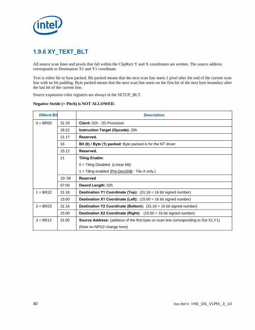
40 Doc Ref #: IHD_OS_V1Pt5_3_10
1.9.6 XY_TEXT_BLT
All source scan lines and pixels that fall within the ClipRect Y and X coordinates are written. The source address corresponds to Destination X1 and Y1 coordinate.
Text is either bit or byte packed. Bit packed means that the next scan line starts 1 pixel after the end of the current scan line with no bit padding. Byte packed means that the next scan line starts on the first bit of the next byte boundary after the last bit of the current line.
Source expansion color registers are always in the SETUP_BLT.
Negative Stride (= Pitch) is NOT ALLOWED.
DWord Bit Description
0 = BR00 31:29 Client: 02h - 2D Processor
28:22 Instruction Target (Opcode): 26h
21:17 Reserved.
16 Bit (0) / Byte (1) packed: Byte packed is for the NT driver
15:12 Reserved.
11 Tiling Enable:
0 = Tiling Disabled (Linear blit)
1 = Tiling enabled (Pre-DevSNB : Tile-X only.)
10: 08 Reserved
07:00 Dword Length: 02h
1 = BR22 31:16 Destination Y1 Coordinate (Top): (31:16 = 16 bit signed number)
15:00 Destination X1 Coordinate (Left): (15:00 = 16 bit signed number)
2 = BR23 31:16 Destination Y2 Coordinate (Bottom): (31:16 = 16 bit signed number)
15:00 Destination X2 Coordinate (Right): (15:00 = 16 bit signed number)
3 = BR12 31:00 Source Address: (address of the first byte on scan line corresponding to Dst X1,Y1)
(Note no NPO2 change here)

Doc Ref #: IHD_OS_V1Pt5_3_10 41
1.9.7 XY_TEXT_IMMEDIATE_BLT
This instruction allows the Driver to send data through the instruction stream that eliminates the read latency of reading a source from memory. If an operand is in system cacheable memory and either small or only accessed once, it can be copied directly to the instruction stream versus to graphics accessible memory.
The IMMEDIATE_BLT data MUST transfer an even number of doublewords. The BLT engine will hang if it does not get an even number of doublewords.
All source scan lines and pixels that fall within the ClipRect X and Y coordinates are written. The source data corresponds to Destination X1 and Y1 coordinate.
Source expansion color registers are always in the SETUP_BLT.
NEGATIVE STRIDE (= PITCH) IS NOT ALLOWED.
DWord Bit Description
0 = BR00 31:29 Client: 02h – 2D Processor
28:22 Instruction Target (Opcode): 31h
21:17 Reserved.
16 Bit (0) / Byte (1) packed: Byte packed is for the NT driver
15:12 Reserved.
11 Tiling Enable:
0 = Tiling Disabled (Linear blit)
1 = Tiling enabled (Pre-DevSNB : Tile-X only.)
10: 08 Reserved
07:00 Dword Length : 01+ DWL = (Number of Immediate double words)h
1 = BR22 31:16 Destination Y1 Coordinate (Top): (31:16 = 16 bit signed number)
15:00 Destination X1 Coordinate (Left): (15:00 = 16 bit signed number)
2 = BR23 31:16 Destination Y2 Coordinate (Bottom): (31:16 = 16 bit signed number)
15:00 Destination X2 Coordinate (Right): (15:00 = 16 bit signed number)
3 31:00 Immediate Data DW 0:
4 31:00 Immediate Data DW 1:
5 thru DWL+3
S Immediate Data DWs 2 through DWORD_LENGTH (DWL):

42 Doc Ref #: IHD_OS_V1Pt5_3_10
1.9.8 XY_COLOR_BLT
COLOR_BLT is the simplest BLT operation. It performs a color fill to the destination (with a possible ROP). The only operand is the destination operand which is written dependent on the raster operation. The solid pattern color is stored in the pattern background register.
This instruction is optimized to run at the maximum memory write bandwidth.
The typical (and fastest) Raster operation code = F0 which performs a copy of the pattern background register to the destination.
DWord Bit Description
0 = BR00 31:29 Client: 02h - 2D Processor
28:22 Instruction Target (Opcode): 50h
21:20 32 bpp byte mask: (21 =1= write alpha channel; 20=1= write RGB channels)
19:12 Reserved.
11 Tiling Enable:
0 = Tiling Disabled (Linear blit)
1 = Tiling enabled (Pre-DevSNB : Tile-X only)
10: 08 Reserved
07:00 Dword Length: 04h
1 = BR13 31 Reserved.
30 Clipping Enable: (1 = enabled; 0 = disabled)
29:26 Reserved.
25:24 Color Depth: 00 = 8 bit color 01 = 16 bit color (565) 10 = 16 bit color (1555) 11 = 32 bit color
23:16 Raster Operation:
15:00 Destination Pitch in DWords: [15:00] 2’s complement
For Tiled surfaces (bit_11 enabled) this ptich is of 512Byte granularity FOR Tile-X, 128B granularity for Tile-Y, and can be upto 128Kbytes (or 32KDwords).
2 = BR22 31:16 Destination Y1 Coordinate (Top): (31:16 = 16 bit signed number)
15:00 Destination X1 Coordinate (Left): (15:00 = 16 bit signed number)
3 = BR23 31:16 Destination Y2 Coordinate (Bottom): (31:16 = 16 bit signed number)
15:00 Destination X2 Coordinate (Right): (15:00 = 16 bit signed number)
4 = BR09 31:00 Destination Base Address: (base address of the destination surface: X=0, Y=0)
When Tiling is enabled (Bit_11 enabled), this address is limited to 4Kbytes.
5 = BR16 31:00 Solid Pattern Color: 8 bit = [7:0], 16 bit = [15:0], 32 bit = [31:0]
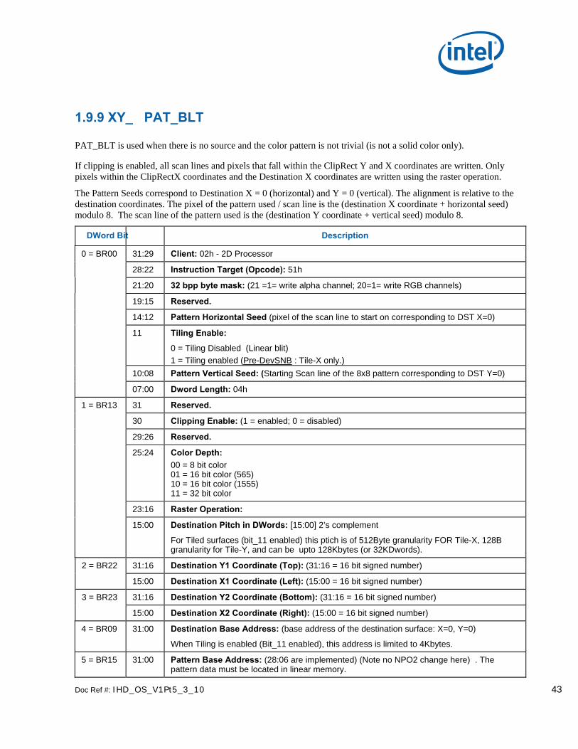
Doc Ref #: IHD_OS_V1Pt5_3_10 43
1.9.9 XY_ PAT_BLT
PAT_BLT is used when there is no source and the color pattern is not trivial (is not a solid color only).
If clipping is enabled, all scan lines and pixels that fall within the ClipRect Y and X coordinates are written. Only pixels within the ClipRectX coordinates and the Destination X coordinates are written using the raster operation.
The Pattern Seeds correspond to Destination X = 0 (horizontal) and Y = 0 (vertical). The alignment is relative to the destination coordinates. The pixel of the pattern used / scan line is the (destination X coordinate + horizontal seed) modulo 8. The scan line of the pattern used is the (destination Y coordinate + vertical seed) modulo 8.
DWord Bit Description
0 = BR00 31:29 Client: 02h - 2D Processor
28:22 Instruction Target (Opcode): 51h
21:20 32 bpp byte mask: (21 =1= write alpha channel; 20=1= write RGB channels)
19:15 Reserved.
14:12 Pattern Horizontal Seed (pixel of the scan line to start on corresponding to DST X=0)
11 Tiling Enable:
0 = Tiling Disabled (Linear blit) 1 = Tiling enabled (Pre-DevSNB : Tile-X only.)
10:08 Pattern Vertical Seed: (Starting Scan line of the 8x8 pattern corresponding to DST Y=0)
07:00 Dword Length: 04h
1 = BR13 31 Reserved.
30 Clipping Enable: (1 = enabled; 0 = disabled)
29:26 Reserved.
25:24 Color Depth: 00 = 8 bit color 01 = 16 bit color (565) 10 = 16 bit color (1555) 11 = 32 bit color
23:16 Raster Operation:
15:00 Destination Pitch in DWords: [15:00] 2’s complement
For Tiled surfaces (bit_11 enabled) this ptich is of 512Byte granularity FOR Tile-X, 128B granularity for Tile-Y, and can be upto 128Kbytes (or 32KDwords).
2 = BR22 31:16 Destination Y1 Coordinate (Top): (31:16 = 16 bit signed number)
15:00 Destination X1 Coordinate (Left): (15:00 = 16 bit signed number)
3 = BR23 31:16 Destination Y2 Coordinate (Bottom): (31:16 = 16 bit signed number)
15:00 Destination X2 Coordinate (Right): (15:00 = 16 bit signed number)
4 = BR09 31:00 Destination Base Address: (base address of the destination surface: X=0, Y=0)
When Tiling is enabled (Bit_11 enabled), this address is limited to 4Kbytes.
5 = BR15 31:00 Pattern Base Address: (28:06 are implemented) (Note no NPO2 change here) . The pattern data must be located in linear memory.

44 Doc Ref #: IHD_OS_V1Pt5_3_10
1.9.10 XY_ PAT_CHROMA_BLT
PAT_BLT is used when there is no source and the color pattern is not trivial (is not a solid color only).
All scan lines and pixels that fall within the ClipRect Y and X coordinates are written. Only pixels within the ClipRectX coordinates and the Destination X coordinates are written using the raster operation.
The Pattern Seeds correspond to Destination X = 0 (horizontal) and Y = 0 (vertical). The alignment is relative to the destination coordinates. The pixel of the pattern used / scan line is the (destination X coordinate + horizontal seed) modulo 8. The scan line of the pattern used is the (destination Y coordinate + vertical seed) modulo 8.
DWord Bit Description
0 = BR00 31:29 Client: 02h - 2D Processor 28:22 Instruction Target (Opcode): 76h 21:20 32 bpp byte mask: (21 =1= write alpha channel; 20=1= write RGB channels) 19:17 Transparency Range Mode: (chroma-key) – Dst Chroma-key modes ONLY (SRC ILLEGAL) 16:15 Reserved. 14:12 Pattern Horizontal Seed (pixel of the scan line to start on corresponding to DST X=0) 11 Tiling Enable:
0 = Tiling Disabled (Linear blit) 1 = Tiling enabled (Pre-DevSNB : Tile-X only.)
10:08 Pattern Vertical Seed: (Starting Scan line of the 8x8 pattern corresponding to DST Y=0) 07:00 Dword Length: 06h 1 = BR13 31 Reserved. 30 Clipping Enable: (1 = enabled; 0 = disabled) 29:26 Reserved.
25:24 Color Depth: 00 = 8 bit color 01 = 16 bit color (565) 10 = 16 bit color (1555) 11 = 32 bit color
23:16 Raster Operation: 15:00 Destination Pitch in DWords: [15:00] 2’s complement
For Tiled surfaces (bit_11 enabled) this ptich is of 512Byte granularity FOR Tile-X, 128B granularity for Tile-Y, and can be upto 128Kbytes (or 32KDwords).
2 = BR22 31:16 Destination Y1 Coordinate (Top): (31:16 = 16 bit signed number)
15:00 Destination X1 Coordinate (Left): (15:00 = 16 bit signed number)
3 = BR23 31:16 Destination Y2 Coordinate (Bottom): (31:16 = 16 bit signed number)
15:00 Destination X2 Coordinate (Right): (15:00 = 16 bit signed number)
4 = BR09 31:00 Destination Base Address: (base address of the destination surface: X=0, Y=0)
When Tiling is enabled (Bit_11 enabled), this address is limited to 4Kbytes.
5 = BR15 31:00 Pattern Base Address: (26:06 are used, other bits are ignored) (Note no NPO2 change here). The pattern data must be located in linear memory.
6 = BR18 31:00 Transparency Color Low: (Chroma-key Low = Pixel Greater or Equal) 7 = BR19 31:00 Transparency Color High: (Chroma-key High = Pixel Less or Equal)

Doc Ref #: IHD_OS_V1Pt5_3_10 45
1.9.11 XY_ PAT_BLT_IMMEDIATE
PAT_BLT_IMMEDIATE is used when there is no source and the color pattern is not trivial (is not a solid color only) and the pattern is pulled through the command stream. The immediate data sizes are 64 bytes (16 DWs), 128 bytes (32 DWs), or 256 (64DWs) for 8, 16, and 32 bpp color patterns.
All scan lines and pixels that fall within the ClipRect Y and X coordinates are written. Only pixels within the ClipRectX coordinates and the Destination X coordinates are written using the raster operation.
The Pattern Seeds correspond to Destination X = 0 (horizontal) and Y = 0 (vertical). The alignment is relative to the destination coordinates. The pixel of the pattern used / scan line is the (destination X coordinate + horizontal seed) modulo 8. The scan line of the pattern used is the (destination Y coordinate + vertical seed) modulo 8.
DWord Bit Description
0 = BR00 31:29 Client: 02h - 2D Processor 28:22 Instruction Target (Opcode): 72h 21:20 32 bpp byte mask: (21 =1= write alpha channel; 20=1= write RGB channels) 19:15 Reserved. 14:12 Pattern Horizontal Seed (pixel of the scan line to start on corresponding to DST X=0) 11 Tiling Enable:
0 = Tiling Disabled (Linear blit) 1 = Tiling enabled (Pre-DevSNB : Tile-X only.)
10:08 Pattern Vertical Seed: (starting scan line of the 8x8 pattern corresponding to DST Y=0) 07:00 Dword Length: 03+ DWL = (Number of Immediate double)h 1 = BR13 31 Reserved 30 Clipping Enable: (1 = enabled; 0 = disabled) 29:26 Reserved.
25:24 Color Depth: 00 = 8 bit color 01 = 16 bit color (565) 10 = 16 bit color (1555) 11 = 32 bit color
23:16 Raster Operation: 15:00 Destination Pitch in DWords: [15:00] 2’s complement
For Tiled surfaces (bit_11 enabled) this ptich is of 512Byte granularity FOR Tile-X, 128B granularity for Tile-Y, and can be upto 128Kbytes (or 32KDwords).
2 = BR22 31:16 Destination Y1 Coordinate (Top): (31:16 = 16 bit signed number) 15:00 Destination X1 Coordinate (Left): (15:00 = 16 bit signed number) 3 = BR23 31:16 Destination Y2 Coordinate (Bottom): (31:16 = 16 bit signed number) 15:00 Destination X2 Coordinate (Right): (15:00 = 16 bit signed number) 4 = BR09 31:00 Destination Base Address: (base address of the destination surface: X=0, Y=0)
When Tiling is enabled (Bit_11 enabled), this address is limited to 4Kbytes. 5 31:00 Immediate Data DW 0: 6 31:00 Immediate Data DW 1: 7 thru DWL+3
S Immediate Data DWs 2 through DWORD_LENGTH (DWL):
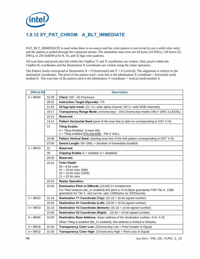
46 Doc Ref #: IHD_OS_V1Pt5_3_10
1.9.12 XY_PAT_CHROM A_BLT_IMMEDIATE
PAT_BLT_IMMEDIATE is used when there is no source and the color pattern is not trivial (is not a solid color only) and the pattern is pulled through the command stream. The immediate data sizes are 64 bytes (16 DWs), 128 bytes (32 DWs), or 256 (64DWs) for 8, 16, and 32 bpp color patterns.
All scan lines and pixels that fall within the ClipRect Y and X coordinates are written. Only pixels within the ClipRectX coordinates and the Destination X coordinates are written using the raster operation.
The Pattern Seeds correspond to Destination X = 0 (horizontal) and Y = 0 (vertical). The alignment is relative to the destination coordinates. The pixel of the pattern used / scan line is the (destination X coordinate + horizontal seed) modulo 8. The scan line of the pattern used is the (destination Y coordinate + vertical seed) modulo 8.
DWord Bit Description 0 = BR00 31:29 Client: 02h - 2D Processor 28:22 Instruction Target (Opcode): 77h 21:20 32 bpp byte mask: (21 =1= write alpha channel; 20=1= write RGB channels) 19:17 Transparency Range Mode: (chroma-key) – Dst Chroma-key modes ONLY (SRC ILLEGAL) 16:15 Reserved. 14:12 Pattern Horizontal Seed (pixel of the scan line to start on corresponding to DST X=0) 11 Tiling Enable:
0 = Tiling Disabled (Linear blit) 1 = Tiling enabled (Pre-DevSNB : Tile-X only.)
10:08 Pattern Vertical Seed: (starting scan line of the 8x8 pattern corresponding to DST Y=0) 07:00 Dword Length: 05+ DWL = (Number of Immediate double)h 1 = BR13 31 Reserved. 30 Clipping Enable (1 = enabled; 0 = disabled) 29:26 Reserved.
25:24 Color Depth: 00 = 8 bit color 01 = 16 bit color (565) 10 = 16 bit color (1555) 11 = 32 bit color
23:16 Raster Operation: 15:00 Destination Pitch in DWords: [15:00] 2’s complement
For Tiled surfaces (bit_11 enabled) this ptich is of 512Byte granularity FOR Tile-X, 128B granularity for Tile-Y, and can be upto 128Kbytes (or 32KDwords).
2 = BR22 31:16 Destination Y1 Coordinate (Top): (31:16 = 16 bit signed number) 15:00 Destination X1 Coordinate (Left): (15:00 = 16 bit signed number) 3 = BR23 31:16 Destination Y2 Coordinate (Bottom): (31:16 = 16 bit signed number) 15:00 Destination X2 Coordinate (Right): (15:00 = 16 bit signed number) 4 = BR09 31:00 Destination Base Address: (base address of the destination surface: X=0, Y=0)
When Tiling is enabled (Bit_11 enabled), this address is limited to 4Kbytes. 5 = BR18 31:00 Transparency Color Low: (Chroma-key Low = Pixel Greater or Equal) 6 = BR19 31:00 Transparency Color High: (Chroma-key High = Pixel Less or Equal)

Doc Ref #: IHD_OS_V1Pt5_3_10 47
DWord Bit Description 7 31:00 Immediate Data DW 0: 8 31:00 Immediate Data DW 1: 9 thru DWL+3
S Immediate Data DWs 2 through DWORD_LENGTH (DWL):
1.9.13 XY_MONO_PAT_BLT MONO_PAT_BLT is used when we have no source and the monochrome pattern is not trivial (is not a solid color only). The monochrome pattern is loaded from the instruction stream.
All scan lines and pixels that fall within the ClipRect Y and X coordinates are written. Only pixels within the ClipRectX coordinates and the Destination X coordinates are written using the raster operation.
The Pattern Seeds correspond to Destination X = 0 (horizontal) and Y = 0 (vertical). The alignment is relative to the destination coordinates. The pixel of the pattern used / scan line is the (destination X coordinate + horizontal seed) modulo 8. The scan line of the pattern used is the (destination Y coordinate + vertical seed) modulo 8.
The monochrome pattern transparency mode indicates whether to use the pattern background color or de-assert the write enables when the bit in the pattern is 0. When the pattern bit is 1, then the pattern foreground color is used in the ROP operation.
DWord Bit Description
0 = BR00 31:29 Client: 02h - 2D Processor 28:22 Instruction Target (Opcode) : 52h 21:20 32 bpp byte mask: (21 =1= write alpha channel; 20=1= write RGB channels) 19:15 Reserved. 14:12 Pattern Horizontal Seed: (pixel of the scan line to start on corresponding to DST X=0) 11 Tiling Enable:
0 = Tiling Disabled (Linear blit)
1 = Tiling enabled (Pre-DevSNB : Tile-X only.) 10:08 Pattern Vertical Seed: (starting scan line of the 8x8 pattern corresponding to DST Y=0) 07:00 Dword Length: 07h 1 = BR13 31 Reserved. 30 Clipping Enable (1 = enabled; 0 = disabled) 29 Reserved. 28 Mono Pattern Transparency Mode: (1 = transparency enabled; 0 = use background) 27:26 Reserved.
25:24 Color Depth: 00 = 8 bit color 01 = 16 bit color (565) 10 = 16 bit color (1555) 11 = 32 bit color
23:16 Raster Operation:
15:00 Destination Pitch in DWords: [15:00] 2’s complement
For Tiled surfaces (bit_11 enabled) this ptich is of 512Byte granularity FOR Tile-X, 128B granularity for Tile-Y, and can be upto 128Kbytes (or 32KDwords).

48 Doc Ref #: IHD_OS_V1Pt5_3_10
DWord Bit Description
2 = BR22 31:16 Destination Y1 Coordinate (Top): 31:16 = 16 bit signed number)
15:00 Destination X1 Coordinate (Left): (15:00 = 16 bit signed number)
3 = BR23 31:16 Destination Y2 Coordinate (Bottom): (31:16 = 16 bit signed number)
15:00 Destination X2 Coordinate (Right): (15:00 = 16 bit signed number)
4 = BR09 31:00 Destination Base Address: (base address of the destination surface: X=0, Y=0)
When Tiling is enabled (Bit_11 enabled), this address is limited to 4Kbytes.
5 = BR16 31:00 Pattern Background Color: 8 bit = [7:0], 16 bit = [15:0], 32 bit = [31:0]
6 = BR17 31:00 Pattern Foreground Color: 8 bit = [7:0], 16 bit = [15:0], 32 bit = [31:0]
7 = BR20 31:00 Pattern Data 0: (least significant DW)
8 = BR21 31:00 Pattern Data 1: (most significant DW)
1.9.14 XY_MONO_PAT_FIXED_BLT MONO_PAT_FIXED_BLT is used when we have no source and the monochrome pattern is not trivial (is not a solid color only). The monochrome pattern is one of 10 fixed patterns described below. The pattern seeds can still be used with the fixed patterns, creating even more fixed patterns. This eliminates 2 doublewords compared to the XY_MONO_PAT_BLT command packet.
All scan lines and pixels that fall within the ClipRect Y and X coordinates are written. Only pixels within the ClipRectX coordinates and the Destination X coordinates are written using the raster operation.
The Pattern Seeds correspond to Destination X = 0 (horizontal) and Y = 0 (vertical). The alignment is relative to the destination coordinates. The pixel of the pattern used / scan line is the (destination X coordinate + horizontal seed) modulo 8. The scan line of the pattern used is the (destination Y coordinate + vertical seed) modulo 8.
The monochrome pattern transparency mode indicates whether to use the pattern background color or de-assert the write enables when the bit in the pattern is 0. When the pattern bit is 1, then the pattern foreground color is used in the ROP operation.
DWord Bit Description
0 = BR00 31:29 Client: 02h - 2D Processor
28:22 Instruction Target (Opcode): 59h
21:20 32 bpp byte mask: (21 =1= write alpha channel; 20=1= write RGB channels)
19 Reserved.
18:15 Fixed Pattern: 0000 HS_HORIZONTAL 0001 HS_VERTICAL 0010 HS_FDIAGONAL 0011 HS_BDIAGONAL 0100 HS_CROSS 0101 HS_DIAGCROSS 0110 Reserved 0111 Reserved 1000 Screen Door 1001 SD Wide 1010 Walking Bit (one) 1011 Walking Zero 1100 Reserved

Doc Ref #: IHD_OS_V1Pt5_3_10 49
DWord Bit Description
1101 Reserved 1110 Reserved
14:12 Pattern Horizontal Seed: (pixel of the scan line to start on corresponding to DST X=0)
11 Tiling Enable:
0 = Tiling Disabled (Linear blit)
1 = Tiling enabled (Pre-DevSNB : Tile-X only.)
10:08 Pattern Vertical Seed: (starting scan line of the 8x8 pattern corresponding to DST Y=0)
07:00 Dword Length: 05h
1 = BR13 31 Reserved.
30 Clipping Enable (1 = enabled; 0 = disabled)
29 Reserved.
28 Mono Pattern Transparency Mode: (1 = transparency enabled; 0 = use background)
27 Bit Mask Enable: (1 = use bit mask register for bit writes; 0 = disabled)
27:26 Reserved.
25:24 Color Depth: 00 = 8 bit color 01 = 16 bit color (565) 10 = 16 bit color (1555) 11 = 32 bit color
23:16 Raster Operation:
15:00 Destination Pitch in DWords: [15:00] 2’s complement
For Tiled surfaces (bit_11 enabled) this ptich is of 512Byte granularity FOR Tile-X, 128B granularity for Tile-Y, and can be upto 128Kbytes (or 32KDwords).
2 = BR22 31:16 Destination Y1 Coordinate (Top): (31:16 = 16 bit signed number)
15:00 Destination X1 Coordinate (Left): (15:00 = 16 bit signed number)
3 = BR23 31:16 Destination Y2 Coordinate (Bottom): (31:16 = 16 bit signed number)
15:00 Destination X2 Coordinate (Right): (15:00 = 16 bit signed number)
4 = BR09 31:00 Destination Base Address: (base address of the destination surface: X=0, Y=0)
When Tiling is enabled (Bit_11 enabled), this address is limited to 4Kbytes.
5 = BR16 31:00 Pattern Background Color: 8 bit = [7:0], 16 bit = [15:0], 32 bit = [31:0]
6 = BR17 31:00 Pattern Foreground Color: 8 bit = [7:0], 16 bit = [15:0], 32 bit = [31:0]
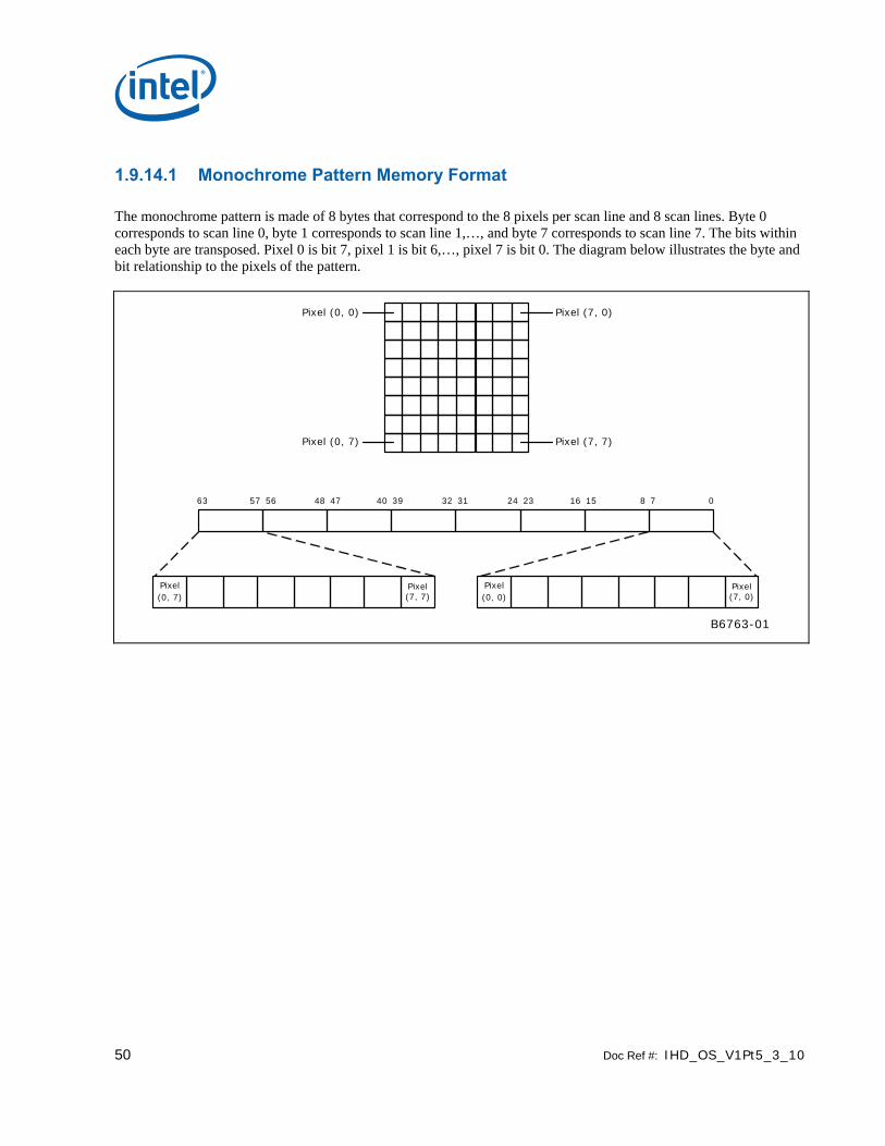
50 Doc Ref #: IHD_OS_V1Pt5_3_10
1.9.14.1 Monochrome Pattern Memory Format
The monochrome pattern is made of 8 bytes that correspond to the 8 pixels per scan line and 8 scan lines. Byte 0 corresponds to scan line 0, byte 1 corresponds to scan line 1,…, and byte 7 corresponds to scan line 7. The bits within each byte are transposed. Pixel 0 is bit 7, pixel 1 is bit 6,…, pixel 7 is bit 0. The diagram below illustrates the byte and bit relationship to the pixels of the pattern.
B6763-01
63 57 56
Pixel (7, 7)Pixel (0, 7)
Pixel (0, 0)
Pixel(0, 0)
Pixel(7, 0)
Pixel(0, 7)
Pixel(7, 7)
Pixel (7, 0)
48 47 40 39 32 31 24 23 16 15 8 7 0

Doc Ref #: IHD_OS_V1Pt5_3_10 51
1.9.14.2 HS_HORIZ ONTAL 0 Bit 7 0 0,0 7,0
0 0 0 0 0 0 0 00 0 0 0 0 0 0 00 0 0 0 0 0 0 01 1 1 1 1 1 1 10 0 0 0 0 0 0 00 0 0 0 0 0 0 00 0 0 0 0 0 0 00 0 0 0 0 0 0 0
1.9.14.3 HS_VERTI CAL 1 Bit 7 0 0,0 7,0
0 0 0 0 1 0 0 00 0 0 0 1 0 0 00 0 0 0 1 0 0 00 0 0 0 1 0 0 00 0 0 0 1 0 0 00 0 0 0 1 0 0 00 0 0 0 1 0 0 00 0 0 0 1 0 0 0
1.9.14.4 HS_F DIAGONAL 2 Bit 7 0 0,0 7,0
1 0 0 0 0 0 0 00 1 0 0 0 0 0 00 0 1 0 0 0 0 00 0 0 1 0 0 0 00 0 0 0 1 0 0 00 0 0 0 0 1 0 00 0 0 0 0 0 1 00 0 0 0 0 0 0 1
1.9.14.5 HS_BDIAGONAL 3 Bit 7 0 0,0 7,0
0 0 0 0 0 0 0 10 0 0 0 0 0 1 00 0 0 0 0 1 0 00 0 0 0 1 0 0 00 0 0 1 0 0 0 00 0 1 0 0 0 0 00 1 0 0 0 0 0 01 0 0 0 0 0 0 0

52 Doc Ref #: IHD_OS_V1Pt5_3_10
1.9.14.6 HS_CROSS 4 Bit 7 0 0,0 7,0
0 0 0 0 1 0 0 00 0 0 0 1 0 0 00 0 0 0 1 0 0 01 1 1 1 1 1 1 10 0 0 0 1 0 0 00 0 0 0 1 0 0 00 0 0 0 1 0 0 00 0 0 0 1 0 0 0
1.9.14.7 HS_DIAG CROSS 5 Bit 7 0 0,0 7,0
1 0 0 0 0 0 0 10 1 0 0 0 0 1 00 0 1 0 0 1 0 00 0 0 1 1 0 0 00 0 0 1 1 0 0 00 0 1 0 0 1 0 00 1 0 0 0 0 1 01 0 0 0 0 0 0 1
1.9.14.8 Screen Door 8 Bit 7 0 0,0 7,0
0 1 0 1 0 1 0 11 0 1 0 1 0 1 00 1 0 1 0 1 0 11 0 1 0 1 0 1 00 1 0 1 0 1 0 11 0 1 0 1 0 1 00 1 0 1 0 1 0 11 0 1 0 1 0 1 0
1.9.14.9 SD Wide 9 Bit 7 0 0,0 7,0
1 1 0 0 1 1 0 00 0 1 1 0 0 1 11 1 0 0 1 1 0 00 0 1 1 0 0 1 11 1 0 0 1 1 0 00 0 1 1 0 0 1 11 1 0 0 1 1 0 00 0 1 1 0 0 1 1

Doc Ref #: IHD_OS_V1Pt5_3_10 53
1.9.14.10 Walking Bit (One) A Bit 7 0 0,0 7,0
1 0 0 0 1 0 0 00 1 0 0 0 1 0 00 0 1 0 0 0 1 00 0 0 1 0 0 0 11 0 0 0 1 0 0 00 1 0 0 0 1 0 00 0 1 0 0 0 1 00 0 0 1 0 0 0 1
1.9.14.11 Walking Zero B Bit 7 0 0,0 7,0
0 1 1 1 0 1 1 11 0 1 1 1 0 1 11 1 0 1 1 1 0 11 1 1 0 1 1 1 00 1 1 1 0 1 1 11 0 1 1 1 0 1 11 1 0 1 1 1 0 11 1 1 0 1 1 1 0
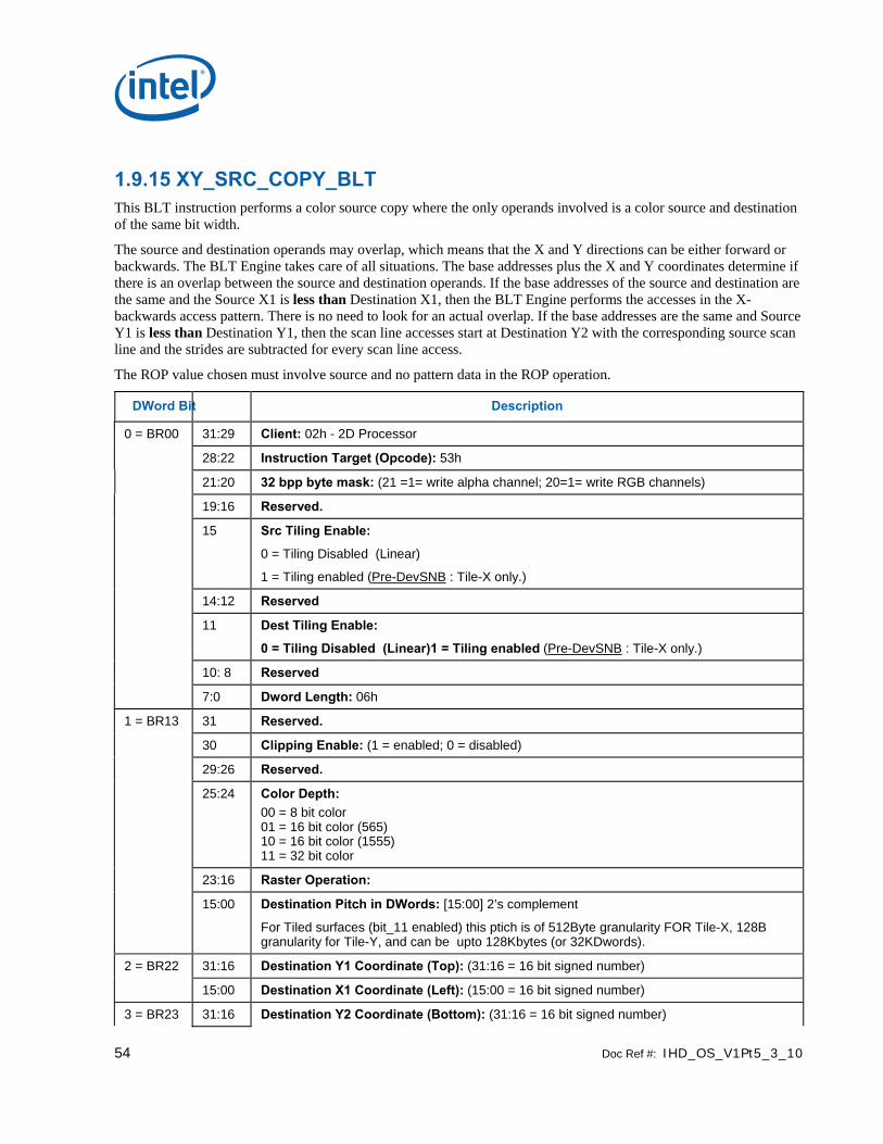
54 Doc Ref #: IHD_OS_V1Pt5_3_10
1.9.15 XY_SRC_COPY_BLT This BLT instruction performs a color source copy where the only operands involved is a color source and destination of the same bit width.
The source and destination operands may overlap, which means that the X and Y directions can be either forward or backwards. The BLT Engine takes care of all situations. The base addresses plus the X and Y coordinates determine if there is an overlap between the source and destination operands. If the base addresses of the source and destination are the same and the Source X1 is less than Destination X1, then the BLT Engine performs the accesses in the X-backwards access pattern. There is no need to look for an actual overlap. If the base addresses are the same and Source Y1 is less than Destination Y1, then the scan line accesses start at Destination Y2 with the corresponding source scan line and the strides are subtracted for every scan line access.
The ROP value chosen must involve source and no pattern data in the ROP operation.
DWord Bit Description
0 = BR00 31:29 Client: 02h - 2D Processor
28:22 Instruction Target (Opcode): 53h
21:20 32 bpp byte mask: (21 =1= write alpha channel; 20=1= write RGB channels)
19:16 Reserved.
15 Src Tiling Enable:
0 = Tiling Disabled (Linear)
1 = Tiling enabled (Pre-DevSNB : Tile-X only.)
14:12 Reserved
11 Dest Tiling Enable:
0 = Tiling Disabled (Linear)1 = Tiling enabled (Pre-DevSNB : Tile-X only.)
10: 8 Reserved
7:0 Dword Length: 06h
1 = BR13 31 Reserved.
30 Clipping Enable: (1 = enabled; 0 = disabled)
29:26 Reserved.
25:24 Color Depth: 00 = 8 bit color 01 = 16 bit color (565) 10 = 16 bit color (1555) 11 = 32 bit color
23:16 Raster Operation:
15:00 Destination Pitch in DWords: [15:00] 2’s complement
For Tiled surfaces (bit_11 enabled) this ptich is of 512Byte granularity FOR Tile-X, 128B granularity for Tile-Y, and can be upto 128Kbytes (or 32KDwords).
2 = BR22 31:16 Destination Y1 Coordinate (Top): (31:16 = 16 bit signed number)
15:00 Destination X1 Coordinate (Left): (15:00 = 16 bit signed number)
3 = BR23 31:16 Destination Y2 Coordinate (Bottom): (31:16 = 16 bit signed number)

Doc Ref #: IHD_OS_V1Pt5_3_10 55
DWord Bit Description
15:00 Destination X2 Coordinate (Right): (15:00 = 16 bit signed number)
4 = BR09 31:00 Destination Base Address: (base address of the destination surface: X=0, Y=0)
When Dest Tiling is enabled (Bit 11 enabled), this address is limited to 4Kbytes.
5 = BR26 31:16 Source Y1 Coordinate (Top): (31:16 = 16 bit signed number)
15:00 Source X1 Coordinate (Left): (15:00 = 16 bit signed number)
31:16 Reserved
6 = BR11 15:00 Source Pitch (double word aligned) and in DWords: [15:00] 2’s complement.
For Tiled surfaces (bit_11 enabled) this ptich is of 512Byte granularity FOR Tile-X, 128B granularity for Tile-Y, and can be upto 128Kbytes (or 32KDwords).
7 = BR12 31:00 Source Base Address: (base address of the source surface: X=0, Y=0)
When Src Tiling is enabled (Bit 15 enabled), this address is limited to 4Kbytes.
1.9.16 XY_ SRC_COPY_CHROMA_BLT This BLT instruction performs a color source copy with chroma-keying where the only operands involved is a color source and destination of the same bit width.
The source and destination operands may overlap, which means that the X and Y directions can be either forward or backwards. The BLT Engine takes care of all situations. The base addresses plus the X and Y coordinates determine if there is an overlap between the source and destination operands. If the base addresses of the source and destination are the same and the Source X1 is less than Destination X1, then the BLT Engine performs the accesses in the X-backwards access pattern. There is no need to look for an actual overlap. If the base addresses are the same and Source Y1 is less than Destination Y1, then the scan line accesses start at Destination Y2 with the corresponding source scan line and the strides are subtracted for every scan line access.
The ROP value chosen must involve source and no pattern data in the ROP operation.
DWord Bit Description
0 = BR00 31:29 Client: 02h - 2D Processor
28:22 Instruction Target (Opcode): 73h
21:20 32 bpp byte mask: (21 =1= write alpha channel; 20=1= write RGB channels)
19:17 Transparency Range Mode: (chroma-key)
16 Reserved
15 Src Tiling Enable:
0 = Tiling Disabled (Linear)
1 = Tiling enabled (Pre-DevSNB : Tile-X only.)
14:12 Reserved
11 Dest Tiling Enable:
0 = Tiling Disabled (Linear)
1 = Tiling enabled (Pre-DevSNB : Tile-X only.)
10: 08 Reserved

56 Doc Ref #: IHD_OS_V1Pt5_3_10
DWord Bit Description
07:00 Dword Length: 08h
1 = BR13 31 Reserved.
30 Clipping Enable: (1 = enabled; 0 = disabled)
29:26 Reserved.
25:24 Color Depth: 00 = 8 bit color 01 = 16 bit color (565) 10 = 16 bit color (1555) 11 = 32 bit color
23:16 Raster Operation:
15:00 Destination Pitch in DWords: [15:00] 2’s complement
For Tiled surfaces (bit_11 enabled) this ptich is of 512Byte granularity FOR Tile-X, 128B granularity for Tile-Y, and can be upto 128Kbytes (or 32KDwords).
2 = BR22 31:16 Destination Y1 Coordinate (Top): (31:16 = 16 bit signed number)
15:00 Destination X1 Coordinate (Left): (15:00 = 16 bit signed number)
3 = BR23 31:16 Destination Y2 Coordinate (Bottom): (31:16 = 16 bit signed number)
15:00 Destination X2 Coordinate (Right): (15:00 = 16 bit signed number)
4 = BR09 31:00 Destination Base Address: (base address of the destination surface: X=0, Y=0)
When Dest Tiling is enabled (Bit 11 enabled), this address is limited to 4Kbytes.
5 = BR26 31:16 Source Y1 Coordinate (Top): (31:16 = 16 bit signed number)
15:00 Source X1 Coordinate (Left): (15:00 = 16 bit signed number)
31:16 Reserved.
6 = BR11 15:00 Source Pitch (double word aligned) and in DWords: [15:00] 2’s complement.
For Tiled surfaces (bit_11 enabled) this ptich is of 512Byte granularity FOR Tile-X, 128B granularity for Tile-Y, and can be upto 128Kbytes (or 32KDwords).
7 = BR12 31:00 Source Base Address: (base address of the source surface: X=0, Y=0)
When Src Tiling is enabled (Bit 15 enabled), this address is limited to 4Kbytes.
8 = BR18 31:00 Transparency Color Low: (Chroma-key Low = Pixel Greater or Equal)
9 = BR19 31:00 Transparency Color High: (Chroma-key High = Pixel Less or Equal)

Doc Ref #: IHD_OS_V1Pt5_3_10 57
1.9.17 XY_MONO_SRC_COPY_BLT This BLT instruction performs a monochrome source copy where the only operands involved is a monochrome source and destination. The source and destination operands cannot overlap therefore the X and Y directions are always forward.
All non-text monochrome sources are word aligned. At the end of a scan line of monochrome source, all bits until the next word boundary are ignored. The monochrome source data bit position field [2:0] indicates the bit position within the first byte of the scan line that should be used as the first source pixel which corresponds to the destination X1 coordinate.
The monochrome source transparency mode indicates whether to use the source background color or de-assert the write enables when the bit in the source is 0. When the source bit is 1, then the source foreground color is used in the ROP operation. The ROP value chosen must involve source and no pattern data in the ROP operation. Negative Stride (= Pitch) is NOT ALLOWED.
DWord Bit Description
0 = BR00 31:29 Client: 02h - 2D Processor
28:22 Instruction Target (Opcode): 54h
21:20 32 bpp byte mask: (21 =1= write alpha channel; 20=1= write RGB channels)
19:17 Monochrome source data bit position of the first pixel within a byte per scan line.
16:12 Reserved.
11 Tiling Enable:
0 = Tiling Disabled (Linear blit)
1 = Tiling enabled (Pre-DevSNB : Tile-X only.)
10: 08 Reserved
07:00 Doubleword Length: 06h
1 = BR13 31 Reserved.
30 Clipping Enable: (1 = enabled; 0 = disabled)
29 Mono Source Transparency Mode: (1 = transparency enabled; 0 = use background)
28:26 Reserved.
25:24 Color Depth: 00 = 8 bit color 01 = 16 bit color (565) 10 = 16 bit color (1555) 11 = 32 bit color
23:16 Raster Operation:
15:00 Destination Pitch in DWords: [15:00] 2’s complement
For Tiled surfaces (bit_11 enabled) this ptich is of 512Byte granularity FOR Tile-X, 128B granularity for Tile-Y, and can be upto 128Kbytes (or 32KDwords).
2 = BR22 31:16 Destination Y1 Coordinate (Top): (31:16 = 16 bit signed number)
15:00 Destination X1 Coordinate (Left): (15:00 = 16 bit signed number)
3 = BR23 31:16 Destination Y2 Coordinate (Bottom): (31:16 = 16 bit signed number)

58 Doc Ref #: IHD_OS_V1Pt5_3_10
DWord Bit Description
15:00 Destination X2 Coordinate (Right): (15:00 = 16 bit signed number)
4 = BR09 31:00 Destination Base Address: (base address of the destination surface: X=0, Y=0)
When Tiling is enabled (Bit_11 enabled), this address is limited to 4Kbytes.
5 = BR12 31:00 Source Address: (address corresponding to DST X1,Y1) (Note no NPO2 change here)
6 = BR18 31:00 Source Background Color: 8 bit = [7:0], 16 bit = [15:0], 32 bit = [31:0]
7 = BR19 31:00 Source Foreground Color: 8 bit = [7:0], 16 bit = [15:0], 32 bit = [31:0]
1.9.18 XY_MONO_SRC_COPY_ IMMEDIATE_BLT This instruction allows the Driver to send monochrome data through the instruction stream, eliminating the read latency of the source during command execution.
The IMMEDIATE_BLT data MUST transfer an even number of doublewords and the exact number of quadwords.
All non-text monochrome sources are word aligned. At the end of a scan line of monochrome source, all bits until the next word boundary are ignored. The Monochrome source data bit position field [2:0] indicates the bit position within the first byte of the scan line that should be used as the first source pixel which corresponds to the destination X1 coordinate.
The monochrome source transparency mode indicates whether to use the source background color or de-assert the write enables when the bit in the source is 0. When the source bit is 1, then the source foreground color is used in the ROP operation. The ROP value chosen must involve source and no pattern data in the ROP operation.
The monochrome source data supplied corresponds to the Destination X1 and Y1 coordinates.
Negative Stride (= Pitch) is NOT ALLOWED.

Doc Ref #: IHD_OS_V1Pt5_3_10 59
DWord Bit Description
0 = BR00 31:29 Client: 02h - 2D Processor
28:22 Instruction Target (Opcode): 71h
21:20 32 bpp byte mask: (21 =1= write alpha channel; 20=1= write RGB channels)
19:17 Monochrome source data bit position of the first pixel within a byte per scan line.
16:12 Reserved.
11 Tiling Enable:
0 = Tiling Disabled (Linear blit)
1 = Tiling enabled (Pre-DevSNB : Tile-X only.)
10: 08 Reserved
07:00 Dword Length: 05+ DWL = (Number of Immediate double words)h
1 = BR13 31 Reserved.
30 Clipping Enable: (1 = enabled; 0 = disabled)
29 Mono Source Transparency Mode: (1 = transparency enabled; 0 = use background)
28:26 Reserved.
25:24 Color Depth: 00 = 8 bit color 01 = 16 bit color (565) 10 = 16 bit color (1555) 11 = 32 bit color
23:16 Raster Operation:
15:00 Destination Pitch in DWords: [15:00] 2’s complement
For Tiled surfaces (bit_11 enabled) this ptich is of 512Byte granularity FOR Tile-X, 128B granularity for Tile-Y, and can be upto 128Kbytes (or 32KDwords).
2 = BR22 31:16 Destination Y1 Coordinate (Top): (31:16 = 16 bit signed number)
15:00 Destination X1 Coordinate (Left): (15:00 = 16 bit signed number)
3 = BR23 31:16 Destination Y2 Coordinate (Bottom): (31:16 = 16 bit signed number)
15:00 Destination X2 Coordinate (Right): (15:00 = 16 bit signed number)
4 = BR09 31:00 Destination Base Address: (base address of the destination surface: X=0, Y=0)
When Tiling is enabled (Bit_11 enabled), this address is limited to 4Kbytes.
5 = BR18 31:00 Source Background Color: 8 bit = [7:0], 16 bit = [15:0], 32 bit = [31:0]
6 = BR19 31:00 Source Foreground Color: 8 bit = [7:0], 16 bit = [15:0], 32 bit = [31:0]
7 31:00 Immediate Data DW 0:
8 31:00 Immediate Data DW 1:
9 thru DWL+4
S Immediate Data DWs 2 through DWORD_LENGTH (DWL):

60 Doc Ref #: IHD_OS_V1Pt5_3_10
1.9.19 XY_FULL_BLT The full BLT is the most comprehensive BLT instruction. It provides the ability to specify all 3 operands: destination, source, and pattern. The source and pattern operands are the same bit width as the destination operand.
The source and destination operands may overlap, which means that the X and Y directions can be either forward or backwards. The BLT Engine takes care of all situations. The base addresses plus the X and Y coordinates determine if there is an overlap between the source and destination operands. If the base addresses of the source and destination are the same and the Source X1 is less than Destination X1, then the BLT Engine performs the accesses in the X-backwards access pattern. There is no need to look for an actual overlap. If the base addresses are the same and Source Y1 is less than Destination Y1, then the scan line accesses start at Destination Y2 with the corresponding source scan line and the strides are subtracted for every scan line access.
All scan lines and pixels that fall within the ClipRect Y and X coordinates are written. Only pixels within the ClipRectX coordinates and the Destination X coordinates are written using the raster operation.
The Pattern Seeds correspond to Destination X = 0 (horizontal) and Y = 0 (vertical). The alignment is relative to the destination coordinates. The pixel of the pattern used / scan line is the (destination X coordinate + horizontal seed) modulo 8. The scan line of the pattern used is the (destination Y coordinate + vertical seed) modulo 8.
DWord Bit Description
0 = BR00 31:29 Client: 02h - 2D Processor
28:22 Instruction Target (Opcode): 55h
21:20 32 bpp byte mask: (21 =1= write alpha channel; 20=1= write RGB channels)
19:16 Reserved.
15 Src Tiling Enable:
0 = Tiling Disabled (Linear)
1 = Tiling enabled (Pre-DevSNB : Tile-X only.)
14:12 Pattern Horizontal Seed (pixel of the scan line to start on corresponding to DST X=0)
11 Dest Tiling Enable:
0 = Tiling Disabled (Linear blit)
1 = Tiling enabled (Pre-DevSNB : Tile-X only.)
10:08 Pattern Vertical Seed: (starting scan line of the 8x8 pattern corresponding to DST Y=0)
07:00 Doubleword Length: 07h
1 = BR13 31 Reserved.
30 Clipping Enable: (1 = enabled; 0 = disabled)
29:26 Reserved.
25:24 Color Depth: 00 = 8 bit color 01 = 16 bit color (565) 10 = 16 bit color (1555) 11 = 32 bit color
23:16 Raster Operation:
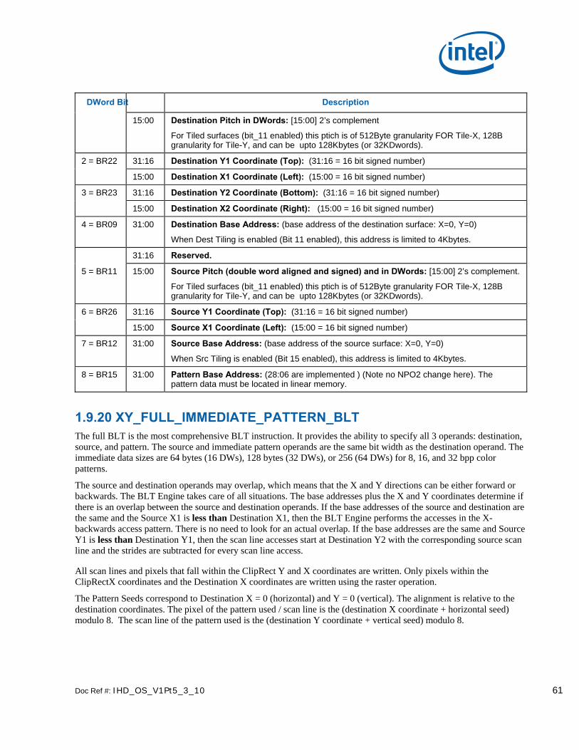
Doc Ref #: IHD_OS_V1Pt5_3_10 61
DWord Bit Description
15:00 Destination Pitch in DWords: [15:00] 2’s complement
For Tiled surfaces (bit_11 enabled) this ptich is of 512Byte granularity FOR Tile-X, 128B granularity for Tile-Y, and can be upto 128Kbytes (or 32KDwords).
2 = BR22 31:16 Destination Y1 Coordinate (Top): (31:16 = 16 bit signed number)
15:00 Destination X1 Coordinate (Left): (15:00 = 16 bit signed number)
3 = BR23 31:16 Destination Y2 Coordinate (Bottom): (31:16 = 16 bit signed number)
15:00 Destination X2 Coordinate (Right): (15:00 = 16 bit signed number)
4 = BR09 31:00 Destination Base Address: (base address of the destination surface: X=0, Y=0)
When Dest Tiling is enabled (Bit 11 enabled), this address is limited to 4Kbytes.
31:16 Reserved.
5 = BR11 15:00 Source Pitch (double word aligned and signed) and in DWords: [15:00] 2’s complement.
For Tiled surfaces (bit_11 enabled) this ptich is of 512Byte granularity FOR Tile-X, 128B granularity for Tile-Y, and can be upto 128Kbytes (or 32KDwords).
6 = BR26 31:16 Source Y1 Coordinate (Top): (31:16 = 16 bit signed number)
15:00 Source X1 Coordinate (Left): (15:00 = 16 bit signed number)
7 = BR12 31:00 Source Base Address: (base address of the source surface: X=0, Y=0)
When Src Tiling is enabled (Bit 15 enabled), this address is limited to 4Kbytes.
8 = BR15 31:00 Pattern Base Address: (28:06 are implemented ) (Note no NPO2 change here). The pattern data must be located in linear memory.
1.9.20 XY_FULL_IMMEDIATE_PATTERN_BLT The full BLT is the most comprehensive BLT instruction. It provides the ability to specify all 3 operands: destination, source, and pattern. The source and immediate pattern operands are the same bit width as the destination operand. The immediate data sizes are 64 bytes (16 DWs), 128 bytes (32 DWs), or 256 (64 DWs) for 8, 16, and 32 bpp color patterns.
The source and destination operands may overlap, which means that the X and Y directions can be either forward or backwards. The BLT Engine takes care of all situations. The base addresses plus the X and Y coordinates determine if there is an overlap between the source and destination operands. If the base addresses of the source and destination are the same and the Source X1 is less than Destination X1, then the BLT Engine performs the accesses in the X-backwards access pattern. There is no need to look for an actual overlap. If the base addresses are the same and Source Y1 is less than Destination Y1, then the scan line accesses start at Destination Y2 with the corresponding source scan line and the strides are subtracted for every scan line access.
All scan lines and pixels that fall within the ClipRect Y and X coordinates are written. Only pixels within the ClipRectX coordinates and the Destination X coordinates are written using the raster operation.
The Pattern Seeds correspond to Destination X = 0 (horizontal) and Y = 0 (vertical). The alignment is relative to the destination coordinates. The pixel of the pattern used / scan line is the (destination X coordinate + horizontal seed) modulo 8. The scan line of the pattern used is the (destination Y coordinate + vertical seed) modulo 8.

62 Doc Ref #: IHD_OS_V1Pt5_3_10
DWord Bit Description
0 = BR00 31:29 Client: 02h - 2D Processor
28:22 Instruction Target (Opcode): 74h
21:20 32 bpp byte mask: (21 =1= write alpha channel; 20=1= write RGB channels)
19:16 Reserved.
15 Src Tiling Enable:
0 = Tiling Disabled (Linear)
1 = Tiling enabled (Pre-DevSNB : Tile-X only.)
14:12 Pattern Horizontal Seed: (pixel of the scan line to start on corresponding to DST X=0)
11 Dest Tiling Enable:
0 = Tiling Disabled (Linear)
1 = Tiling enabled (Pre-DevSNB : Tile-X only.)
10:8 Pattern Vertical Seed: (starting scan line of the 8x8 pattern corresponding to DST Y=0)
7:0 Doubleword Length: 06+ DWL = (Number of Immediate double words)h
1 = BR13 31 Reserved.
30 Clipping Enable: (1 = enabled; 0 = disabled)
29:26 Reserved.
25:24 Color Depth: 00 = 8 bit color 01 = 16 bit color (565) 10 = 16 bit color (1555) 11 = 32 bit color
23:16 Raster Operation:
15:00 Destination Pitch in DWords: [15:00] 2’s complement
For Tiled surfaces (bit_11 enabled) this ptich is of 512Byte granularity FOR Tile-X, 128B granularity for Tile-Y, and can be upto 128Kbytes (or 32KDwords).
2 = BR22 31:16 Destination Y1 Coordinate (Top): (31:16 = 16 bit signed number)
15:00 Destination X1 Coordinate (Left): (15:00 = 16 bit signed number)
3 = BR23 31:16 Destination Y2 Coordinate (Bottom): (31:16 = 16 bit signed number)
15:00 Destination X2 Coordinate (Right): (15:00 = 16 bit signed number)
4 = BR09 31:00 Destination Base Address: (base address of the destination surface: X=0, Y=0)
When Dest Tiling is enabled (Bit 11 enabled), this address is limited to 4Kbytes.
31:16 Reserved.
5 = BR11 15:00 Source Pitch (double word aligned and signed) and in DWords: [15:00] 2’s complement.
For Tiled surfaces (bit_11 enabled) this ptich is of 512Byte granularity FOR Tile-X, 128B granularity for Tile-Y, and can be upto 128Kbytes (or 32KDwords).
6 = BR26 31:16 Source Y1 Coordinate (Top): (31:16 = 16 bit signed number)
15:00 Source X1 Coordinate (Left): (15:00 = 16 bit signed number)

Doc Ref #: IHD_OS_V1Pt5_3_10 63
DWord Bit Description
7 = BR12 31:00 Source Base Address: (base address of the source surface: X=0, Y=0)
When Src Tiling is enabled (Bit 15 enabled), this address is limited to 4Kbytes.
8 31:00 Immediate Data DW 0:
9 31:00 Immediate Data DW 1:
A thru DWL+4
S Immediate Data DWs 2 through DWORD_LENGTH (DWL):

64 Doc Ref #: IHD_OS_V1Pt5_3_10
1.9.21 XY_FULL_MONO_SRC_BLT The full BLT is the most comprehensive BLT instruction. It provides the ability to specify all 3 operands: destination, source, and pattern. The source operand is monochrome and the pattern operand is the same bit width as the destination.
The monochrome source transparency mode indicates whether to use the source background color or de-assert the write enables when the bit in the source is 0. When the source bit is 1, then the source foreground color is used in the ROP operation.
All non-text and non-immediate monochrome sources are word aligned. At the end of a scan line the monochrome source, the remaining bits until the next word boundary are ignored. The Monochrome source data bit position field [2:0] indicates which bit position within the first byte should be used as the first source pixel which corresponds to the Destination X1 coordinate.
All scan lines and pixels that fall within the ClipRect Y and X coordinates are written. Only pixels within the ClipRectX coordinates and the Destination X coordinates are written using the raster operation.
The Pattern Seeds correspond to Destination X = 0 (horizontal) and Y = 0 (vertical). The alignment is relative to the destination coordinates. The pixel of the pattern used / scan line is the (destination X coordinate + horizontal seed) modulo 8. The scan line of the pattern used is the (destination Y coordinate + vertical seed) modulo 8.
Negative Stride (= Pitch) is NOT ALLOWED
DWord Bit Description
0 = BR00 31:29 Client: 02h - 2D Processor
28:22 Instruction Target (Opcode): 56h
21:20 32 bpp byte mask: (21 =1= write alpha channel; 20=1= write RGB channels)
19:17 Monochrome source data bit position of the first pixel within a byte per scan line.
16:15 Reserved.
14:12 Pattern Horizontal Seed: (pixel of the scan line to start on corresponding to DST X=0)
11 Tiling Enable:
0 = Tiling Disabled (Linear blit)
1 = Tiling enabled (Pre-DevSNB : Tile-X only.)
10:08 Pattern Vertical Seed: (starting address of the 8x8 pattern corresponding to DST Y=0)
07:00 Doubleword Length : 07h
1 = BR13 31 Reserved.
30 Clipping Enable: (1 = enabled; 0 = disabled)
29 Mono Source Transparency Mode: (1 = transparency enabled; 0 = use background)
28:27 Reserved.
26 Reserved.

Doc Ref #: IHD_OS_V1Pt5_3_10 65
DWord Bit Description
25:24 Color Depth: 00 = 8 bit color 01 = 16 bit color (565) 10 = 16 bit color (1555) 11 = 32 bit color
23:16 Raster operation:
15:00 Destination Pitch in DWords: [15:00] 2’s complement
For Tiled surfaces (bit_11 enabled) this ptich is of 512Byte granularity FOR Tile-X, 128B granularity for Tile-Y, and can be upto 128Kbytes (or 32KDwords).
2 = BR22 31:16 Destination Y1 Coordinate (Top): (31:16 = 16 bit signed number)
15:00 Destination X1 Coordinate (Left): (15:00 = 16 bit signed number)
3 = BR23 31:16 Destination Y2 Coordinate (Bottom): (31:16 = 16 bit signed number)
15:00 Destination X2 Coordinate (Right): (15:00 = 16 bit signed number)
4 = BR09 31:00 Destination Base Address: (base address of the destination surface: X=0, Y=0)
When Tiling is enabled (Bit_11 enabled), this address is limited to 4Kbytes.
5 = BR12 31:00 Mono Source Address: (address corresponds to DST X1, Y1) (Note no NPO2 change here)
6 = BR18 31:00 Source Background Color: 8 bit = [7:0], 16 bit = [15:0], 32 bit = [31:0]
7 = BR19 31:00 Source Foreground Color: 8 bit = [7:0], 16 bit = [15:0], 32 bit = [31:0]
8 = BR15 31:00 Pattern Base Address: (28:06 are implemented ) (Note no NPO2 change here). The pattern data must be located in linear memory.

66 Doc Ref #: IHD_OS_V1Pt5_3_10
1.9.22 XY_FULL_MONO_SRC_ IMMEDIATE_PATTERN_BLT
The full BLT is the most comprehensive BLT instruction. It provides the ability to specify all 3 operands: destination, source, and pattern. The source operand is a monochrome and the immediate pattern operand is the same bit width as the destination. The immediate data sizes are 64 bytes (16 DWs), 128 bytes (32 DWs), or 256 (64DWs) for 8, 16, and 32 bpp color patterns.
The monochrome source transparency mode indicates whether to use the source background color or de-assert the write enables when the bit in the source is 0. When the source bit is 1, then the source foreground color is used in the ROP operation.
All non-text monochrome sources are word aligned. At the end of a scan line the monochrome source, the remaining bits until the next word boundary are ignored. The Monochrome source data bit position field [2:0] indicates which bit position within the first byte should be used as the first source pixel which corresponds to the destination X1 coordinate.
All scan lines and pixels that fall within the ClipRect Y and X coordinates are written. Only pixels within the ClipRectX coordinates and the Destination X coordinates are written using the raster operation.
The Pattern Seeds correspond to Destination X = 0 (horizontal) and Y = 0 (vertical). The alignment is relative to the destination coordinates. The pixel of the pattern used / scan line is the (destination X coordinate + horizontal seed) modulo 8. The scan line of the pattern used is the (destination Y coordinate + vertical seed) modulo 8.
Negative Stride (= Pitch) is NOT ALLOWED.
DWord Bit Description
0 = BR00 31:29 Client: 02h - 2D Processor
28:22 Instruction Target (Opcode): 75h
21:20 32 bpp byte mask: (21 =1= write alpha channel; 20=1= write RGB channels)
19:17 Monochrome source data bit position of the first pixel within a byte per scan line.
16:15 Reserved.
14:12 Pattern Horizontal Seed: (pixel of the scan line to start on corresponding to DST X=0)
11 Tiling Enable:
0 = Tiling Disabled (Linear blit)
1 = Tiling enabled (Pre-DevSNB : Tile-X only.)
10:08 Pattern Vertical Seed: (starting address of the 8x8 pattern corresponding to DST Y=0)
07:00 Doubleword Length : 06+ DWL = (Number of Immediate double words)h
1 = BR13 31 Reserved.
30 Clipping Enable: (1 = enabled; 0 = disabled)
29 Mono Source Transparency Mode: (1 = transparency enabled; 0 = use background)
28:26 Reserved.

Doc Ref #: IHD_OS_V1Pt5_3_10 67
DWord Bit Description
25:24 Color Depth: 00 = 8 bit color 01 = 16 bit color (565) 10 = 16 bit color (1555) 11 = 32 bit color
23:16 Raster operation:
15:00 Destination Pitch in DWords: [15:00] 2’s complement
For Tiled surfaces (bit_11 enabled) this ptich is of 512Byte granularity FOR Tile-X, 128B granularity for Tile-Y, and can be upto 128Kbytes (or 32KDwords).
2 = BR22 31:16 Destination Y1 Coordinate (Top): (31:16 = 16 bit signed number)
15:00 Destination X1 Coordinate (Left): (15:00 = 16 bit signed number)
3 = BR23 31:16 Destination Y2 Coordinate (Bottom): (31:16 = 16 bit signed number)
15:00 Destination X2 Coordinate (Right): (15:00 = 16 bit signed number)
4 = BR09 31:00 Destination Base Address: (base address of the destination surface: X=0, Y=0)
When Tiling is enabled (Bit_11 enabled), this address is limited to 4Kbytes.
5 = BR12 31:00 Mono Source Address: (address corresponds to DST X1, Y1) (Note no NPO2 change here)
6 = BR18 31:00 Source Background Color: 8 bit = [7:0], 16 bit = [15:0], 32 bit = [31:0]
7 = BR19 31:00 Source Foreground Color: 8 bit = [7:0], 16 bit = [15:0], 32 bit = [31:0]
8 31:00 Immediate Data DW 0:
9 31:00 Immediate Data DW 1:
A thru DWL+4
S Immediate Data DWs 2 through DWORD_LENGTH (DWL):

68 Doc Ref #: IHD_OS_V1Pt5_3_10
1.9.23 XY_FULL_MONO_PATTERN_BLT
The full BLT is the most comprehensive BLT instruction. It provides the ability to specify all 3 operands: destination, source, and pattern. The pattern operand is monochrome and the source operand is the same bit width as the destination operand.
The source and destination operands may overlap, which means that the X and Y directions can be either forward or backwards. The BLT Engine takes care of all situations. The base addresses plus the X and Y coordinates determine if there is an overlap between the source and destination operands. If the base addresses of the source and destination are the same and the Source X1 is less than Destination X1, then the BLT Engine performs the accesses in the X-backwards access pattern. There is no need to look for an actual overlap. If the base addresses are the same and Source Y1 is less than Destination Y1, then the scan line accesses start at Destination Y2 with the corresponding source scan line and the strides are subtracted for every scan line access.
The monochrome pattern transparency mode indicates whether to use the pattern background color or de-assert the write enables when the bit in the source is 0. When the source bit is 1, then the pattern foreground color is used in the ROP operation.
All scan lines and pixels that fall within the ClipRect Y and X coordinates are written. Only pixels within the ClipRectX coordinates and the Destination X coordinates are written using the raster operation.
The Pattern Seeds correspond to Destination X = 0 (horizontal) and Y = 0 (vertical). The alignment is relative to the destination coordinates. The pixel of the pattern used / scan line is the (destination X coordinate + horizontal seed) modulo 8. The scan line of the pattern used is the (destination Y coordinate + vertical seed) modulo 8.
Setting both Solid Pattern Select =1 & Mono Pattern Transparency = 1 is mutually exclusive. The device implementation results in NO PIXELs DRAWN.
DWord Bit Description
0 = BR00 31:29 Client: 02h - 2D Processor 28:22 Instruction Target (Opcode): 57h 21:20 32 bpp byte mask: (21 =1= write alpha channel; 20=1= write RGB channels) 19:16 Reserved. 15 Src Tiling Enable:
0 = Tiling Disabled (Linear) 1 = Tiling enabled (Pre-DevSNB : Tile-X only.)
14:12 Pattern Horizontal Seed: (pixel of the scan line to start on corresponding to DST X=0) 11 Dest Tiling Enable:
0 = Tiling Disabled (Linear)
1 = Tiling enabled (Pre-DevSNB : Tile-X only.) 10:08 Pattern Vertical Seed: (starting scan line of the 8x8 pattern corresponding to DST Y=0) 07:00 Dword Length : 0Ah 1 = BR13 31 Solid Pattern Select: (1 = solid pattern; 0 = no solid pattern) 30 Clipping Enable: (1 = enabled; 0 = disabled) 29 Reserved. 28:27 Mono Pattern Transparency Mode: (1 = transparency enabled; 0 = use background) 26 Reserved.

Doc Ref #: IHD_OS_V1Pt5_3_10 69
DWord Bit Description
25:24 Color Depth: 00 = 8 bit color 01 = 16 bit color 10 = 16 bit color (1555) 11 = 32 bit color (565)
23:16 Raster Operation:
15:00 Destination Pitch in DWords: [15:00] 2’s complement
For Tiled surfaces (bit_11 enabled) this ptich is of 512Byte granularity FOR Tile-X, 128B granularity for Tile-Y, and can be upto 128Kbytes (or 32KDwords).
2 = BR22 31:16 Destination Y1 Coordinate (Top): (31:16 = 16 bit signed number)
15:00 Destination X1 Coordinate (Left): (15:00 = 16 bit signed number)
3 = BR23 31:16 Destination Y2 Coordinate (Bottom): (31:16 = 16 bit signed number)
15:00 Destination X2 Coordinate (Right): (15:00 = 16 bit signed number)
4 = BR09 31:00 Destination Base Address: (base address of the destination surface: X=0, Y=0)
When Dest Tiling is enabled (Bit 11 enabled), this address is limited to 4Kbytes.
31:16 Reserved.
5 = BR11 15:00 Source Pitch (double word aligned and signed) and in DWords: [15:00] 2’s complement.
For Tiled surfaces (bit_11 enabled) this ptich is of 512Byte granularity FOR Tile-X, 128B granularity for Tile-Y, and can be upto 128Kbytes (or 32KDwords).
6 = BR26 31:16 Source Y1 Coordinate (Top): (31:16 = 16 bit signed number)
15:00 Source X1 Coordinate (Left): (15:00 = 16 bit signed number)
7 = BR12 31:00 Source Base Address: (base address of the source surface: X=0, Y=0)
When Src Tiling is enabled (Bit 15 enabled), this address is limited to 4Kbytes.
8 = BR16 31:00 Pattern Background Color: 8 bit = [7:0], 16 bit = [15:0], 32 bit = [31:0]
9 = BR17 31:00 Pattern Foreground Color: 8 bit = [7:0], 16 bit = [15:0], 32 bit = [31:0]
A = BR20 31:00 Pattern Data 0: (least significant DW)
B = BR21 31:00 Pattern Data 1: (most significant DW)

70 Doc Ref #: IHD_OS_V1Pt5_3_10
1.9.24 XY_FULL_MONO_ PATTERN_MONO_SRC_BLT
The full BLT provides the ability to specify all 3 operands: destination, source, and pattern. The pattern and source operands are monochrome.
The monochrome source transparency mode indicates whether to use the source background color or de-assert the write enables when the bit in the source is 0. When the source bit is 1, then the source foreground color is used in the ROP operation.
All non-text monochrome sources are word aligned. At the end of a scan line the monochrome source, the remaining bits until the next word boundary are ignored. The Monochrome source data bit position field [2:0] indicates which bit position within the first byte should be used as the first source pixel which corresponds to the destination X1 coordinate.
The monochrome pattern transparency mode indicates whether to use the pattern background color or de-assert the write enables when the bit in the pattern is 0. When the source bit is 1, then the pattern foreground color is used in the ROP operation. The monochrome source transparency mode works identical to the pattern transparency mode.
All scan lines and pixels that fall within the ClipRect Y and X coordinates are written. Only pixels within the ClipRectX coordinates and the Destination X coordinates are written using the raster operation.
The Pattern Seeds correspond to Destination X = 0 (horizontal) and Y = 0 (vertical). The alignment is relative to the destination coordinates. The pixel of the pattern used / scan line is the (destination X coordinate + horizontal seed) modulo 8. The scan line of the pattern used is the (destination Y coordinate + vertical seed) modulo 8.
Setting both Solid Pattern Select =1 & Mono Pattern Transparency = 1 is mutually exclusive. The device implementation results in NO PIXELs DRAWN.
Negative Stride (= Pitch) is NOT ALLOWED.
DWord Bit Description
0 = BR00 31:29 Client: 02h - 2D Processor
28:22 Instruction Target (Opcode): 58h
21:20 32 bpp byte mask: (21 = 1 = write alpha channel; 20 = 1 = write RGB channels)
19:17 Monochrome source data bit position of the first pixel within a byte per scan line.
16:15 Reserved.
14:12 Pattern Horizontal Seed: (pixel of the scan line to start on corresponding to DST X = 0)
11 Tiling Enable:
0 = Tiling Disabled (Linear blit)
1 = Tiling enabled (Pre-DevSNB : Tile-X only.)
10:08 Pattern Vertical Seed: (starting scan line of the 8x8 pattern corresponding to DST Y = 0)
07:00 Doubleword Length : 0Ah
1 = BR13 31 Solid Pattern Select: (1 = solid pattern; 0 = no solid pattern)
30 Clipping Enable (1 = enabled; 0 = disabled)
29 Mono Source Transparency Mode: (1 = transparency enabled; 0 = use background)
28 Mono Pattern Transparency Mode: (1 = transparency enabled; 0 = use background)

Doc Ref #: IHD_OS_V1Pt5_3_10 71
DWord Bit Description
27:26 Reserved.
25:24 Color Depth: 00 = 8 bit color 01 = 16 bit color (565) 10 = 16 bit color (1555) 11 = 32 bit color
23:16 Raster Operation:
15:00 Destination Pitch in DWords: [15:00] 2’s complement
For Tiled surfaces (bit_11 enabled) this ptich is of 512Byte granularity FOR Tile-X, 128B granularity for Tile-Y, and can be upto 128Kbytes (or 32KDwords).
2 = BR22 31:16 Destination Y1 Coordinate (Top): (31:16 = 16 bit signed number)
15:00 Destination X1 Coordinate (Left): (15:00 = 16 bit signed number)
3 = BR23 31:16 Destination Y2 Coordinate (Bottom): (31:16 = 16 bit signed number)
15:00 Destination X2 Coordinate (Right): (15:00 = 16 bit signed number)
4 = BR09 31:00 Destination Base Address: (base address of the destination surface: X=0, Y=0)
When Tiling is enabled (Bit_11 enabled), this address is limited to 4Kbytes.
5 = BR12 31:00 Source Address: (address corresponding to Dst X1,Y1) (Note no NPO2 change here)
6 = BR18 31:00 Source Background Color: 8 bit = [7:0], 16 bit = [15:0], 32 bit = [31:0]
7 = BR19 31:00 Source Foreground Color: 8 bit = [7:0], 16 bit = [15:0], 32 bit = [31:0]
8 = BR16 31:00 Pattern Background Color: 8 bit = [7:0], 16 bit = [15:0], 32 bit = [31:0]
9 = BR17 31:00 Pattern Foreground Color: 8 bit = [7:0], 16 bit = [15:0], 32 bit = [31:0]
A =BR20 31:00 Pattern Data 0: (least significant DW)
B =BR21 31:00 Pattern Data 1: (most significant DW)

72 Doc Ref #: IHD_OS_V1Pt5_3_10
1.10 BLT Engine Instruction Field Definitions
This section describes the BLT Engine instruction fields. These descriptions are in the format of register descriptions. These registers are internal and are not readable. Some of these registers are state that is saved and restored for supporting separate software threads.
1.10.1 BR00—BLT Opcode & Control Memory Offset Address: none Default: 0000 0000 Attributes: not accessible
BR00 is the last executed instruction DWord 0. Bits [22:5] are written by every DW0 of every instruction. Bits [31:30] and [4:0] are status bits. Bits [28:27] are written from the DW0 [15:14] of a Setup instruction and Bit 29 is written with a 1 when ever a Setup instruction is written. Bit 29 is a decode of the Setup instruction Opcode.
31 30 29 28 24
Rsvd Clip Inst
Setup Mono
Pattern
Instruction Target (Opcode)
23 22 21 20 19 17 16
Instruction Target (Opcode)
32 bpp byte mask Monochrome Source Start Bit (0) / Byte (1) Packed
15 14 12 11 10 8
Rsvd Pattern Horizontal Seed Tiling Enable
Transparency Range Mode
7 5 4 3 2 1 0
PatternVertical Seed DST RMW
Color Source
Mono Source
Color Pattern
Mono Pattern
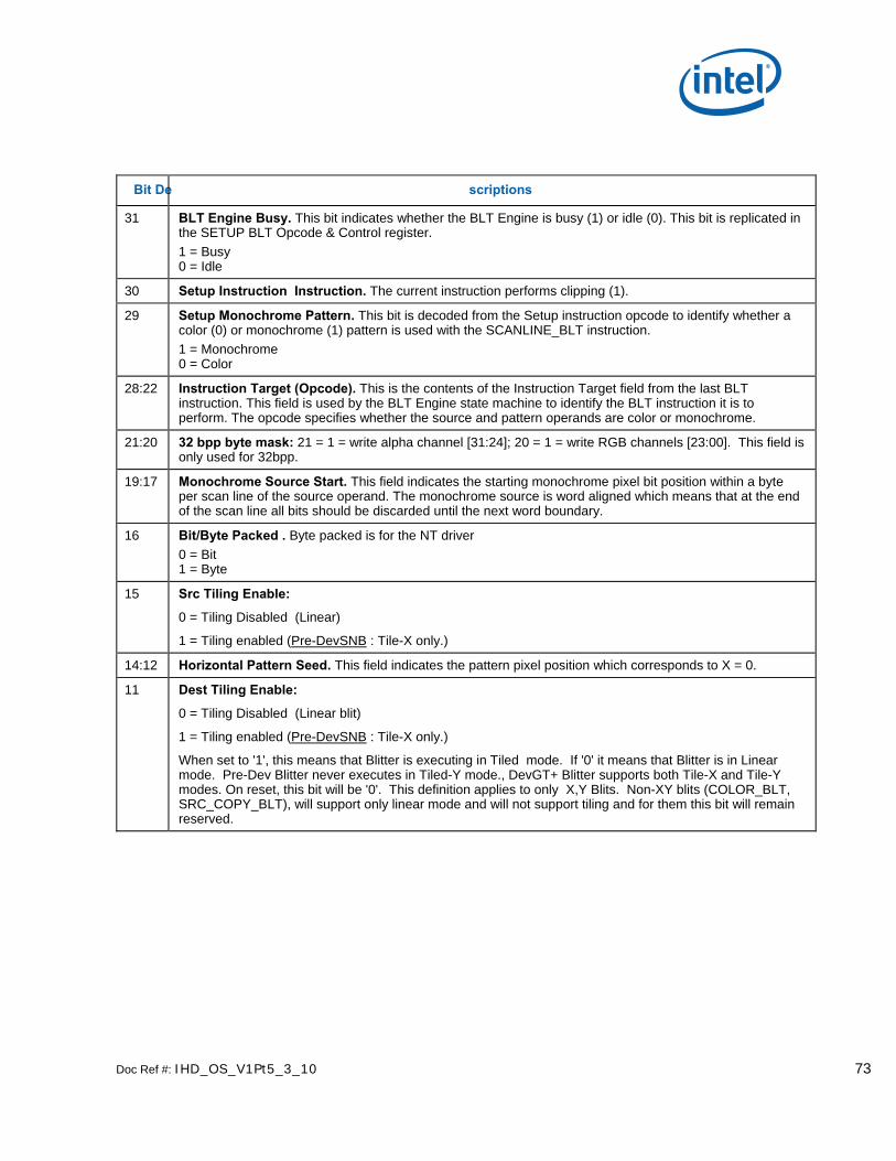
Doc Ref #: IHD_OS_V1Pt5_3_10 73
Bit De scriptions
31 BLT Engine Busy. This bit indicates whether the BLT Engine is busy (1) or idle (0). This bit is replicated in the SETUP BLT Opcode & Control register. 1 = Busy 0 = Idle
30 Setup Instruction Instruction. The current instruction performs clipping (1).
29 Setup Monochrome Pattern. This bit is decoded from the Setup instruction opcode to identify whether a color (0) or monochrome (1) pattern is used with the SCANLINE_BLT instruction. 1 = Monochrome 0 = Color
28:22 Instruction Target (Opcode). This is the contents of the Instruction Target field from the last BLT instruction. This field is used by the BLT Engine state machine to identify the BLT instruction it is to perform. The opcode specifies whether the source and pattern operands are color or monochrome.
21:20 32 bpp byte mask: 21 = 1 = write alpha channel [31:24]; 20 = 1 = write RGB channels [23:00]. This field is only used for 32bpp.
19:17 Monochrome Source Start. This field indicates the starting monochrome pixel bit position within a byte per scan line of the source operand. The monochrome source is word aligned which means that at the end of the scan line all bits should be discarded until the next word boundary.
16 Bit/Byte Packed . Byte packed is for the NT driver 0 = Bit 1 = Byte
15 Src Tiling Enable:
0 = Tiling Disabled (Linear)
1 = Tiling enabled (Pre-DevSNB : Tile-X only.)
14:12 Horizontal Pattern Seed. This field indicates the pattern pixel position which corresponds to X = 0.
11 Dest Tiling Enable:
0 = Tiling Disabled (Linear blit)
1 = Tiling enabled (Pre-DevSNB : Tile-X only.)
When set to '1', this means that Blitter is executing in Tiled mode. If '0' it means that Blitter is in Linear mode. Pre-Dev Blitter never executes in Tiled-Y mode., DevGT+ Blitter supports both Tile-X and Tile-Y modes. On reset, this bit will be '0'. This definition applies to only X,Y Blits. Non-XY blits (COLOR_BLT, SRC_COPY_BLT), will support only linear mode and will not support tiling and for them this bit will remain reserved.

74 Doc Ref #: IHD_OS_V1Pt5_3_10
Bit De scriptions
10:8 Transparency Range Mode. These bits control whether or not the byte(s) at the destination corresponding to a given pixel will be conditionally written, and what those conditions are. This feature can make it possible to perform various masking functions in order to selectively write or preserve graphics data already at the destination.
XX0 = No color transparency mode enabled. This causes normal operation with regard to writing data to the destination.
001 = [Source color transparency] The Transparency Color Low: (Pixel Greater or Equal) (source background register) and the Transparency Color High: (Pixel Less or Equal) (source foreground register) are compared to the source pixels. The range comparisons are done on each component (R,G,B) and then logically ANDed. If the source pixel components are not within the range defined by the Transparency Color registers, then the byte(s) at the destination corresponding to the current pixel are written with the result of the bit-wise operation.
011 = [Source and Alpha color transparency] The Transparency Color Low: (Pixel Greater or Equal) (source background register) and the Transparency Color High: (Pixel Less or Equal) (source foreground register) are compared to the source pixels. The range comparisons are done on each component (A,R,G,B) and then logically ANDed. If the source pixel components are not within the range defined by the Transparency Color registers, then the byte(s) at the destination corresponding to the current pixel are written with the result of the bit-wise operation.
101 = [Destination and Alpha color transparency] The Transparency Color Low: (Pixel Greater or Equal) (source background register) and the Transparency Color High: (Pixel Less or Equal) (source foreground register) are compared to the destination pixels. The range comparisons are done on each component (A,R,G,B) and then logically ANDed. If the destination pixels are within the range, then the byte(s) at the destination corresponding to the current pixel are written with the result of the bit-wise operation.
111 = [Destination color transparency] The Transparency Color Low: (Pixel Greater or Equal) (source background register) and the Transparency Color High: (Pixel Less or Equal) (source foreground register) are compared to the destination pixels. The range comparisons are done on each component (R,G,B) and then logically ANDed. If the destination pixels are within the range, then the byte(s) at the destination corresponding to the current pixel are written with the result of the bit-wise operation.
7:5 Pattern Vertical Seed. This field specifies the pattern scan line which corresponds to Y=0.
4 Destination Read Modify Write. This bit is decoded from the last instruction’s opcode field and Destination Transparency Mode to identify whether a Destination read is needed.
3 Color Source. This bit is decoded from the last instructions opcode field to identify whether a color (1) source is used.
2 Monochrome Source. This bit is decoded from the last instructions opcode field to identify whether a monochrome (1) source is used.
1 Color Pattern. This bit is decoded from the last instructions opcode field to identify whether a color (1) pattern is used.
0 Monochrome Pattern. This bit is decoded from the last instructions opcode field to identify whether a monochrome (1) pattern is used.

Doc Ref #: IHD_OS_V1Pt5_3_10 75
1.10.2 BR01—Setup BLT Raster OP, Control, and Destination Offset Memory Offset Address: none Default: 0000 xxxx Attributes: State accessible
BR01 contains the contents of the last Setup instruction DWord 1. It is identical to the BLT Raster OP, Control, and Destination Offset definition, but it is used with the following instructions: PIXEL_BLT, SCANLINE_BLT, and TEXT_BLT.
31 30 29 28 27 26 25 24
Solid Pattern
Clipping Enable
Mono Src Trans
Mono Pat Trans
32 bpp byte mask Color Depth
23 16
Raster Operation
15 0
Destination Pitch (Offset)
Bit De scriptions
31 Solid Pattern Select. This bit applies only when the pattern data is monochrome. This bit determines whether or not the BLT Engine actually performs read operations from the frame buffer in order to load the pattern data. Use of this feature to prevent these read operations can increase BLT Engine performance, if use of the pattern data is indeed not necessary. The BLT Engine is configured to accept either monochrome or color pattern data via the opcode field.
0 = This causes normal operation with regard to the use of the pattern data. The BLT Engine proceeds with the process of reading the pattern data, and the pattern data is used as the pattern operand for all bit-wise operations.
1 = The BLT Engine forgoes the process of reading the pattern data, the presumption is made that all of the bits of the pattern data are set to 0, and the pattern operand for all bit-wise operations is forced to the background color specified in the Color Expansion Background Color Register.
30 Clipping Enabled: 1 = Enabled; 0 = Disabled

76 Doc Ref #: IHD_OS_V1Pt5_3_10
Bit De scriptions
29 Monochrome Source Transparency Mode. This bit applies only when the source data is in monochrome. This bit determines whether or not the byte(s) at the destination corresponding to the pixel to which a given bit of the source data also corresponds will actually be written if that source data bit has the value of 0. This feature can make it possible to use the source as a transparency mask. The BLT Engine is configured to accepted either monochrome or color source data via the opcode field.
0 = This causes normal operation with regard to the use of the source data. Wherever a bit in the source data has the value of 0, the color specified in the background color register is used as the source operand in the bit-wise operation for the pixel corresponding to the source data bit, and the bytes at the destination corresponding to that pixel are written with the result.
1 = Wherever a bit in the source data has the value of 0, the byte(s) at the destination corresponding to the pixel to which the source data bit also corresponds are simply not written, and the data at those byte(s) at the destination are allowed to remain unchanged.
28 Monochrome Pattern Transparency Mode. This bit applies only when the pattern data is monochrome. This bit determines whether or not the byte(s) at the destination corresponding to the pixel to which a given bit of the pattern data also corresponds will actually be written if that pattern data bit has the value of 1. This feature can make it possible to use the pattern as a transparency mask. The BLT Engine is configured to accepted either monochrome or color pattern data via the opcode field.
0 = This causes normal operation with regard to the use of the pattern data. Wherever a bit in the pattern data has the value of 0, the color specified in the background color register is used as the pattern operand in the bit-wise operation for the pixel corresponding to the pattern data bit, and the bytes at the destination corresponding to that pixel are written with the result.
1 = Wherever a bit in the pattern data has the value of 0, the byte(s) at the destination corresponding to the pixel to which the pattern data bit also corresponds are simply not written, and the data at those byte(s) at the destination are allowed to remain unchanged.
27:26 32 bpp byte mask. 21 = 1 = write alpha channel [31:24]; 20 = 1 = write RGB channels [23:00]. This field is only used for 32bpp.
25:24 Color Depth. 00 = 8 Bit Color Depth 01 = 16 Bit Color Depth 10 = 16 Bit Color Depth 11 = 32 Bit Color Depth
23:16 Raster Operation Select. These 8 bits are used to select which one of 256 possible raster operations is to be performed by the BLT Engine. The 8-bit values, and their corresponding raster operations, are intended to correspond to the 256 possible raster operations specified for graphics device drivers. The opcode field must indicate a monochrome source if ROP = F0.

Doc Ref #: IHD_OS_V1Pt5_3_10 77
Bit De scriptions
15:0 Destination Pitch (Offset).
For non-XY Blits, the signed 16bit field allows for specifying upto + 32Kbytes signed pitches in bytes (same as before).
For X, Y Blits with tiled-X surfaces, the pitch for Destination will be 512Byte aligned and should be programmable upto + 128Kbytes. For X, Y Blits with Tiled-Y surfaces, the pitch for Destination will be 128Byte aligned and should be programmable upto + 128Kbytes. In this case, this 16bit signed pitch field is used to specify upto + 32KDWords. For X, Y blits with nontiled surfaces (linear surfaces), this 16bit field can be programmed to byte specification of upto + 32Kbytes (same as before).
These 16 bits store the signed memory address offset value by which the destination address originally specified in the Destination Address Register is incremented or decremented as each scan line’s worth of destination data is written into the frame buffer by the BLT Engine, so that the destination address will point to the next memory address to which the next scan line’s worth of destination data is to be written.
If the intended destination of a BLT operation is within on-screen frame buffer memory, this offset is normally set so that each subsequent scan line’s worth of destination data lines up vertically with the destination data in the scan line, above. However, if the intended destination of a BLT operation is within off-screen memory, this offset can be set so that each subsequent scan line’s worth of destination data is stored at a location immediately after the location where the destination data for the last scan line ended, in order to create a single contiguous block of bytes of destination data at the destination.
1.10.3 BR05—Setup Expansion Background Color Memory Offset Address: none Default: None Attributes: State accessible
31 0
Setup Expansion Background Color Bits [31:0]
Bit De scriptions
31:0 Setup Expansion Background Color Bits [31:0]. These bits provide the one, two, or four bytes worth of color data that select the background color to be used in the color expansion of monochrome pattern or source data for either the SCANLINE_BLT or TEXT_BLT instructions. BR05 is also used as the solid pattern for the PIXEL_BLT instruction.
Whether one, two, or three bytes worth of color data is needed depends upon the color depth to which the BLT Engine has been set. For a color depth of 32bpp, 16bpp and 8bpp, bits [31:0], [15:0] and [7:0], respectively, are used.

78 Doc Ref #: IHD_OS_V1Pt5_3_10
1.10.4 BR06—Setup Expansion Foreground Color Memory Offset Address: none Default: None Attributes: State accessible
31 0
Setup Expansion Foreground Color Bits [31:0]
Bit De scriptions
31:24 Reserved.
31:0 Setup Expansion Foreground Color Bits [31:0]. These bits provide the one, two, or four bytes worth of color data that select the foreground color to be used in the color expansion of monochrome pattern or source data for either the SCANLINE_BLT or TEXT_BLT instructions.
Whether one, two, or three bytes worth of color data is needed depends upon the color depth to which the BLT Engine has been set. For a color depth of 32bpp, 16bpp and 8bpp, bits [31:0], [15:0] and [7:0], respectively, are used.

Doc Ref #: IHD_OS_V1Pt5_3_10 79
1.10.5 BR07—Setup Color Pattern Address Memory Offset Address: none Default: None Attributes: State accessible
31 29 28 16
Reserved Setup Color Pattern Address Bits [28:16]
15 6 5 0
Setup Color Pattern Address Bits [15:6] Reserved
Bit De scriptions
31:29 Reserved. The maximum GC graphics address is 512 MBs.
28:6 Pattern Address. These 23 bits specify the starting address of the color pattern from the SETUP_BLT instruction. This register works identically to the Pattern Address register, but this version is only used with the SCANLINE_BLT instruction execution. The pattern data must be located in linear memory.
The pattern data must be located on a pattern-size boundary. The pattern is always of 8x8 pixels, and therefore, its size is dependent upon its pixel depth. The pixel depth may be 8, 16, or 32 bits per pixel if the pattern is in color (the pixel depth of a color pattern must match the pixel depth to which the graphics system has been set). Monochrome patterns require 8 bytes and is supplied through the instruction. Color patterns of 8, 16, and 32 bits per pixel color depth must start on 64-byte, 128-byte and 256-byte boundaries, respectively.
5:0 Reserved. These bits always return 0 when read.

80 Doc Ref #: IHD_OS_V1Pt5_3_10
1.10.6 BR09—Destination Address Memory Offset Address: None Default: None Attributes: State accessible
31 29 28 0
Reserved Destination and Destination Y1 and Y Address Bits [28:0]
Bit De scriptions
31:29 Reserved.
28:0 Destination Address Bits. When tiling is enabled for XY-blits, this base address should be limited to 4KB. Otherwise for XY blits, there is no restriction and it is same as before.
These 29 bits specify the starting pixel address of the destination data. This register is also the working destination address register and changes as the BLT Engine performs the accesses.
Used as the scan line address (Destination Y Address & Destination Y1 Address) for BLT instructions: PIXEL_BLT, SCANLINE_BLT, and TEXT_BLT. In this case the address points to the first pixel in a scan line and is compared with the ClipRect Y1 & Y2 address registers to determine whether the scan line should be written or not. The Destination Y1 address is the top scan line to be written for text.
Note that for non-XY blits (COLOR_BLT, SRC_COPY_BLT), this address points to the first byte to be written.
This register is always the last register written for a BLT drawing instruction. Writing BR09 starts the BLT engine execution.
Note: Some instructions affect only one scan line (requiring only one coordinate); other instructions affect multiple scan lines and need both coordinates.

Doc Ref #: IHD_OS_V1Pt5_3_10 81
1.10.7 BR11—BLT Source Pitch (Offset) Memory Offset Address: None Default: None Attributes: Not accessible
31 16 15 0
BLT Engine Status - TBS Source Pitch (Offset)
Bit De scriptions
15:0 Source Pitch (Offset) For non-XY Blits with color source operand (SRC_COPY_BLT), the signed 16bit field allows for specifying upto + 32Kbytes signed pitch in bytes (same as before).
For X, Y Blits with tiled-X surfaces, the pitch for Color Source will be 512Byte aligned and should be programmable upto + 128Kbytes. For X, Y Blits with tiled-Y surfaces, the pitch for Color Source will be 128Byte aligned and should be programmable upto + 128Kbytes. In this case, this 16bit signed pitch field is used to specify up to upto + 32KDWords. For X, Y blits with nontiled color source surfaces (linear surfaces), this 16bit field can be programmed to byte specification of upto + 32Kbytes (same as before).
When the color source data is located within the frame buffer or AGP aperture, these signed 16 bits store the memory address offset (pitch) value by which the source address originally specified in the Source Address Register is incremented or decremented as each scan line’s worth of source data is read from the frame buffer by the BLT Engine, so that the source address will point to the next memory address from which the next scan line’s worth of source data is to be read.
Note that if the intended source of a BLT operation is within on-screen frame buffer memory, this offset is normally set to accommodate the fact that each subsequent scan line’s worth of source data lines up vertically with the source data in the scan line, above. However, if the intended source of a BLT operation is within off-screen memory, this offset can be set to accommodate a situation in which the source data exists as a single contiguous block of bytes where in each subsequent scan line’s worth of source data is stored at a location immediately after the location where the source data for the last scan line ended.

82 Doc Ref #: IHD_OS_V1Pt5_3_10
1.10.8 BR12—Source Address Memory Offset Address: None Default: None Attributes: Not accessible
31 29 28 0
Reserved Source Address Bits [28:0]
Bit De scriptions
31:29 Reserved. The maximum GC Graphics address is 512 MBs.
28:0 Source Address Bits [28:0]. When tiling is enabled for XY-blits with Color source surfaces, this base address should be limited to 4KB. Otherwise for XY blits, there is no restriction and it is same as before, including for monosource and text blits.
Note that for non-XY blit with Color Source (SRC_COPY_BLT), this address points to the first byte to be read.
These 29 bits are used to specify the starting pixel address of the color source data. The lower 3 bits are used to indicate the position of the first valid byte within the first Quadword of the source data.

Doc Ref #: IHD_OS_V1Pt5_3_10 83
1.10.9 BR13—BLT Raster OP, Control, and Destination Pitch Memory Offset Address: None Default: 0000 xxxx Attributes: Not accessible
31 30 29 28 27 26 25 24
Solid Pattern
Clipping Enable
Mono Src Trans
Mono Pat Trans
32 bpp byte mask Color Depth
23 16
Raster Operation
15 0
Destination Pitch (Offset)
Bit De scriptions
31 Solid Pattern Select. This bit applies only when the pattern data is monochrome. This bit determines whether or not the BLT Engine actually performs read operations from the frame buffer in order to load the pattern data. Use of this feature to prevent these read operations can increase BLT Engine performance, if use of the pattern data is indeed not necessary. The BLT Engine is configured to accept either monochrome or color pattern data via the opcode field.
0 = This causes normal operation with regard to the use of the pattern data. The BLT Engine proceeds with the process of reading the pattern data, and the pattern data is used as the pattern operand for all bit-wise operations.
1 = The BLT Engine forgoes the process of reading the pattern data, the presumption is made that all of the bits of the pattern data are set to 0, and the pattern operand for all bit-wise operations is forced to the background color specified in the Color Expansion Background Color Register.
30 Clipping Enabled: 1 = Enabled; 0 = Disabled
29 Monochrome Source Transparency Mode. This bit applies only when the source data is in monochrome. This bit determines whether or not the byte(s) at the destination corresponding to the pixel to which a given bit of the source data also corresponds will actually be written if that source data bit has the value of 0. This feature can make it possible to use the source as a transparency mask. The BLT Engine is configured to accepted either monochrome or color source data via the opcode field.
0 = This causes normal operation with regard to the use of the source data. Wherever a bit in the source data has the value of 0, the color specified in the background color register is used as the source operand in the bit-wise operation for the pixel corresponding to the source data bit, and the bytes at the destination corresponding to that pixel are written with the result.
1 = Where a bit in the source data has the value of 0, the byte(s) at the destination corresponding to the pixel to which the source data bit also corresponds are simply not written, and the data at those byte(s) at the destination are allowed to remain unchanged.

84 Doc Ref #: IHD_OS_V1Pt5_3_10
Bit De scriptions
28 Monochrome Pattern Transparency Mode. This bit applies only when the pattern data is monochrome. This bit determines whether or not the byte(s) at the destination corresponding to the pixel to which a given bit of the pattern data also corresponds will actually be written if that pattern data bit has the value of 1. This feature can make it possible to use the pattern as a transparency mask. The BLT Engine is configured to accepted either monochrome or color pattern data via the opcode in the Opcode and Control register.
0 = This causes normal operation with regard to the use of the pattern data. Where a bit in the pattern data has the value of 0, the color specified in the background color register is used as the pattern operand in the bit-wise operation for the pixel corresponding to the pattern data bit, and the bytes at the destination corresponding to that pixel are written with the result.
1= Wherever a bit in the pattern data has the value of 0, the byte(s) at the destination corresponding to the pixel to which the pattern data bit also corresponds are simply not written, and the data at those byte(s) at the destination are allowed to remain unchanged.
25:24 Color Depth. 00 = 8 Bit Color Depth 01 = 16 Bit Color Depth 10 = 24 Bit Color Depth 11 = Reserved
23:16 Raster Operation Select. These 8 bits are used to select which one of 256 possible raster operations is to be performed by the BLT Engine. The 8-bit values, and their corresponding raster operations, are intended to correspond to the 256 possible raster operations specified for graphics device drivers. The opcode must indicate a monochrome source operand if ROP = F0.
15:0 Destination Pitch (Offset). These 16 bits store the signed memory address offset value by which the destination address originally specified in the Destination Address Register is incremented or decremented as each scan line’s worth of destination data is written into the frame buffer by the BLT Engine, so that the destination address will point to the next memory address to which the next scan line’s worth of destination data is to be written.
If the intended destination of a BLT operation is within on-screen frame buffer memory, this offset is normally set so that each subsequent scan line’s worth of destination data lines up vertically with the destination data in the scan line, above. However, if the intended destination of a BLT operation is within off-screen memory, this offset can be set so that each subsequent scan line’s worth of destination data is stored at a location immediately after the location where the destination data for the last scan line ended, in order to create a single contiguous block of bytes of destination data at the destination.

Doc Ref #: IHD_OS_V1Pt5_3_10 85
1.10.10 BR14—Destination Width & Height Memory Offset Address: None Default: None Attributes: Not accessible
BR14 contains the values for the height and width of the data to be BLT. If these values are not correct, such that the BLT Engine is either expecting data it does not receive or receives data it did not expect, the system can hang.
31 29 28 16
Reserved Destination Height
15 13 12 0
Reserved Destination Byte Width
Bit De scriptions
31:29 Reserved.
28:16 Destination Height. These 13 bits specify the height of the destination data in terms of the number of scan lines. This is a working register.
15:13 Reserved.
12:0 Destination Byte Width. These 13 bits specify the width of the destination data in terms of the number of bytes per scan line. The number of pixels per scan line into which this value translates depends upon the color depth to which the graphics system has been set.

86 Doc Ref #: IHD_OS_V1Pt5_3_10
1.10.11 BR15—Color Pattern Address Memory Offset Address: None Default: None Attributes: Not accessible
31 29 28 16
Reserved Color Pattern Address Bits [28:16]
15 6 5 0
Color Pattern Address Bits [15:6] Reserved
. Bit De scriptions
31:29 Reserved. The maximum GC graphics address is 512 MBs.
28:6 Color Pattern Address. There is no change to the Color Pattern address specification due to Non-Power-of-2 change. It remains the same as before. The pattern data must be located in linear memory.
These 23 bits specify the starting address of the pattern.
The pattern data must be located on a pattern-size boundary. The pattern is always of 8x8 pixels, and therefore, its size is dependent upon its pixel depth. The pixel depth may be 8, 16, or 32 bits per pixel if the pattern is in color (the pixel depth of a color pattern must match the pixel depth to which the graphics system has been set). Monochrome patterns require 8 bytes and are applied through the instruction. Color patterns of 8, 16, and 32 bits per pixel color depth must start on 64-byte, 128-byte and 256-byte boundaries, respectively.
5:0 Reserved. These bits always return 0 when read.

Doc Ref #: IHD_OS_V1Pt5_3_10 87
1.10.12 BR16—Pattern Expansion Background & Solid Pattern Color Memory Offset Address: 40040h Default: None Attributes: RO; DWord accessible
31 0
Pattern Expansion Background Color Bits [31:0]
. Bit De scriptions
31:0 Pattern Expansion Background Color Bits [31:0]. These bits provide the one, two, or four bytes worth of color data that select the background color to be used in the color expansion of monochrome pattern data during BLT operations.
Whether one, two, or four bytes worth of color data is needed depends upon the color depth to which the BLT Engine has been set. For a color depth of 32bpp, 16bpp and 8bpp, bits [31:0], [15:0] and [7:0], respectively, are used.
1.10.12.1 BR17—Pattern Expansion Foreground Color Memory Offset Address: None Default: None Attributes: Not accessible
31 0
Pattern Expansion Foreground Color Bits [31:0]
Bit De scriptions
31:0 Pattern Expansion Foreground Color Bits [31:0]. These bits provide the one, two, or four bytes worth of color data that select the foreground color to be used in the color expansion of monochrome pattern data during BLT operations.
Whether one, two, or four bytes worth of color data is needed depends upon the color depth to which the BLT Engine has been set. For a color depth of 32bpp, 16bpp and 8bpp, bits [31:0], [15:0] and [7:0], respectively, are used.

88 Doc Ref #: IHD_OS_V1Pt5_3_10
1.10.13 BR18—Source Expansion Background, and Destination Color Memory Offset Address: None Default: None Attributes: Not accessible
31 0
Source Expansion Background Color Bits [31:0]
Bit De scriptions
31:0 Source Expansion Background Color Bits [31:0]. These bits provide the one, two, or four bytes worth of color data that select the background color to be used in the color expansion of monochrome source data during BLT operations.
This register is also used to support destination transparency mode and Solid color fill.
Whether one, two, three, or four bytes worth of color data is needed depends upon the color depth to which the BLT Engine has been set. For a color depth of 32bpp, 16bpp and 8bpp, bits [31:0], [15:0] and [7:0], respectively, are used.
1.10.14 BR19—Source Expansion Foreground Color Memory Offset Address: None Default: None Attributes: Not accessible
31 0
Pattern Expansion Foreground Color Bits [31:0]
Bit De scriptions
31:0 Pattern/Source Expansion Foreground Color Bits [31:0]. These bits provide the one, two, or four bytes worth of color data that select the foreground color to be used in the color expansion of monochrome source data during BLT operations.
Whether one, two, or four bytes worth of color data is needed depends upon the color depth to which the BLT Engine has been set. For a color depth of 32bpp, 16bpp and 8bpp, bits [31:0], [15:0] and [7:0], respectively, are used.

Doc Ref #: IHD_OS_V1Pt5_3_10 89
2. Blitter (Blt) Engine Command Streamer
2.1 Registers for Blitter Engine
2.1.1 Introduct ion
Each register is at the same offset from 020000h as its primary counterpart is offset from 02000h.
2.1.2 Virtual Memory Control
2.1.2.1 BLT_PP_DIR_BASE – Page Directory Base Register
BLT_PP_DIR_BASE – Page Directory Base Register Register Type: MMIO_BCS Address Offset: 22390h Project: All Default Value: 00000000h Access: R/W Size (in bits): 32 Trusted Type: 1 This register contains the offset into the GGTT where the (current context’s) PPGTT page directory begins. This register is restored with context
Bit De scription
31:16 Page Directory Base Offset Project: All Security: None Default Value: 0h DefaultVaueDesc Format: U15 Address: GraphicsAddress[31:16] Range [0,PPGTT Size - 1 in cachelines]
Contains the cacheline (64-byte) address into the GGTT where the page directory begins.
15:0 Reserved Project: All Format: MBZ
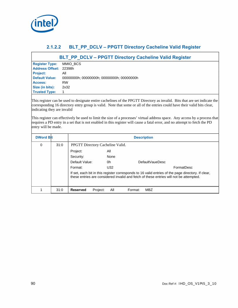
90 Doc Ref #: IHD_OS_V1Pt5_3_10
2.1.2.2 BLT_PP_DCLV – PPGTT Directory Cacheline Valid Register
BLT_PP_DCLV – PPGTT Directory Cacheline Valid Register Register Type: MMIO_BCS Address Offset: 22398h Project: All Default Value: 00000000h; 00000000h; 00000000h; 00000000h Access: RW Size (in bits): 2x32 Trusted Type: 1
This register can be used to designate entire cachelines of the PPGTT Directory as invalid. Bits that are set indicate the corresponding 16 directory entry group is valid. Note that some or all of the entries could have their valid bits clear, indicating they are invalid
This register can effectively be used to limit the size of a processes’ virtual address space. Any access by a process that requires a PD entry in a set that is not enabled in this register will cause a fatal error, and no attempt to fetch the PD entry will be made.
DWord Bit Description
0 31:0 PPGTT Directory Cacheline Valid. Project: All Security: None Default Value: 0h DefaultVaueDesc Format: U32 FormatDesc If set, each bit in this register corresponds to 16 valid entries of the page directory. If clear, these entries are considered invalid and fetch of these entries will not be attempted.
1 31:0 Reserved Project: All Format: MBZ

Doc Ref #: IHD_OS_V1Pt5_3_10 91
2.1.3 Mode and Misc Ctrl Registers
2.1.3.1 BCS_MI_MODE — Mode Register for Software Interface Address Offset: 2209Ch–2209Fh Default Value: 0000 0000h Access: Read/Write Size: 32 bits
The MI_MODE register contains information that controls software interface aspects of the command parser.
Bit De scription
31:16 Masks: A “1” in a bit in this field allows the modification of the corresponding bit in Bits 15:0
15:12 Reserved Read/Write
11 Invalidate UHPTR enable: If bit set H/W clears the valid bit of BCS_UHPTR (4134h, bit 0) when current active head pointer is equal to UHPTR.
10 Reserved Read/Write
9 Ring Idle (Read Only Status bit)
0 = Parser not Idle
1 = Parser Idle
Writes to this bit are not allowed.
8 Stop Ring
0 = Normal Operation.
1 = Parser is turned off.
Software must set this bit to force the Ring and Command Parser to Idle. Software must read a “1” in Ring Idle bit after setting this bit to ensure that the hardware is idle.
Software must clear this bit for Ring to resume normal operation.
7:0 Reserved Read/Write
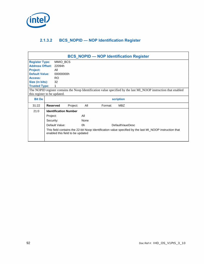
92 Doc Ref #: IHD_OS_V1Pt5_3_10
2.1.3.2 BCS_NOPID — NOP Identification Register
BCS_NOPID — NOP Identification Register Register Type: MMIO_BCS Address Offset: 22094h Project: All Default Value: 00000000h Access: RO Size (in bits): 32 Trusted Type: 1 The NOPID register contains the Noop Identification value specified by the last MI_NOOP instruction that enabled this register to be updated.
Bit De scription
31:22 Reserved Project: All Format: MBZ 21:0 Identification Number
Project: All Security: None Default Value: 0h DefaultVaueDesc This field contains the 22-bit Noop Identification value specified by the last MI_NOOP instruction that enabled this field to be updated

Doc Ref #: IHD_OS_V1Pt5_3_10 93
2.1.3.3 BCS_INST PM—Instruction Parser Mode Register Address Offset: 220C0h–220C3h Default Value: 0000 0000h Access: Read/Write Size: 32 bits
The BCS_INSTPM register is used to control the operation of the BCS Instruction Parser. Certain classes of instructions can be disabled (ignored) – often useful for detecting performance bottlenecks. Also, “Synchronizing Flush” operations can be initiated – useful for ensuring the completion (vs. only parsing) of rendering instructions.
Programming Notes:
• All Reserved bits are implemented
2.1.3.4 BCS_EXCC—Execute Condition Code Register
BCS_EXCC—Execute Condition Code Register Register Type: MMIO_BCS Address Offset: 22028h Project: All Default Value: 00000000h Access: R/W,RO Size (in bits): 32 Trusted Type: 1 This register contains user defined and hardware generated conditions that are used by MI_WAIT_FOR_EVENT commands. An MI_WAIT_FOR_EVENT instruction excludes the executing ring from arbitration if the selected event evaluates to a “1”, while instruction is discarded if the condition evaluates to a “0”. Once excluded a ring is enabled into arbitration when the selected condition evaluates to a “0”.
Bit De scription
31:18 Reserved Project: All Format: MBZ 17 Mask Bits
Format: Mask[1]
This bit serves as a write enable for bit 1. If this register is written with this bit clear the corresponding bit in the field 1 will not be modified. Reading these bits always returns 0s.
16 Mask Bits Format: Mask[0]
These bits serves as a write enable for bit 0. If this register is written with any of these bits clear the corresponding bit in the field 0 will not be modified. Reading these bits always returns 0s.
15:2 Reserved Project: All Format: MBZ 1 Video Command Streamer Condition Codes
The software may signal a Stream Semaphore by setting the Mask bit and Signal Bit together to match the bit field specified in a WAIT_FOR_EVENT (Semaphore).

94 Doc Ref #: IHD_OS_V1Pt5_3_10
BCS_EXCC—Execute Condition Code Register 0 Render Command Streamer Condition Codes
The software may signal a Stream Semaphore by setting the Mask bit and Signal Bit together to match the bit field specified in a WAIT_FOR_EVENT (Semaphore).
2.1.3.5 BRSYNC – Blitter/Render Semaphore Sync Register
BRSYNC – Blitter/Render Semaphore Sync Register Register Type: MMIO_BCS Address Offset: 22040h Project: All Default Value: 00000000h Access: R/W Size (in bits): 32 Trusted Type: 1 This register is written by CS, read by BCS.
Bit De scription
31:0 Semaphore Data Semaphore data for synchronization between blitter engine and render engine..
2.1.3.6 VSYNC – Blitter/Video Semaphore Sync Register
BVSYNC – Blitter/Video Semaphore Sync Register Register Type: MMIO_BCS Address Offset: 22044h Project: All Default Value: 00000000h Access: R/W Size (in bits): 32 Trusted Type: 1 This register is written by VCS, read by BCS.
Bit De scription
31:0 Semaphore Data Semaphore data for synchronization between blitter engine and video codec engine.

Doc Ref #: IHD_OS_V1Pt5_3_10 95
2.1.4 Context Submission
Before submitting a context for the first time, the context image must be properly initialized. Proper initialization includes the ring context registers (ring location, head/tail pointers, etc.) and the page directory.
2.1.4.1 BCS_RCCID—Ring Buffer Current Context ID Register Address Offset: 227C0h–227C4h Default Value: 00 00 00 00h Access: Read/Write Size: 32 bits
This register contains the current “ring context ID” associated with the ring buffer.
Programming Notes:
• The current context registers must not be written directly (via MMIO). The RCCID register should only be updated indirectly from RNCID.
Bit Des cription
63:0 See Context Descriptor for BCS
2.1.4.2 VCS_RNCID—Ring Buffer Next Context ID Register
Address Offset: 22700h–22708h Default Value: 00 00 00 00h Access: Read/Write Size: 64 bits
This register contains the next “ring context ID” associated with the ring buffer.
Programming Notes:
• The current context (RCCID) register can be updated indirectly from this register on a context switch event. Note that the only time a context switch can occur is when MI_ARB_CHECK enables preemption or the current context runs dry (head pointer becomes equal to tail pointer).
Bit Des cription
63:0 See Context Descriptor for BCS

96 Doc Ref #: IHD_OS_V1Pt5_3_10
2.1.4.3 Context Status
A context switch interrupt will be sent anytime a context switch change occurs. This is documented in the “GPU Overview” volume, “Memory Data Formats” chapter. A status DW for the context that was just switched away from will be written to the Context Status Buffer in the Global Hardware Status Page. The status contains the context ID and the reason for the context switch. Note that since there will have been no running contexts when the very first (after reset) context is submitted, the Context ID in the first Context Status DWord will be UNDEFINED.
Bit De scription
31:12 Context ID. Contains the context ID copied from the submitted context.
11:8 Reserved: MBZ
7 Reserved: MBZ
6 Reserved: MBZ
5 Reserved: MBZ
4 Ring Buffer Becoming Empty Caused context to Switch.
3 Reserved: MBZ
2 Reserved: MBZ
1 Waiting on a Semaphore Caused Context to Switch.
0 Reserved: MBZ

Doc Ref #: IHD_OS_V1Pt5_3_10 97
2.1.5 BCS_RINGBUF—Ring Buffer Registers
RINGBUF—Ring Buffer Registers Register Type: MMIO_BCS Address Offset: 22030h Project: All Default Value: 00000000h; 00000000h; 00000000h; 00000000h Access: R/W Size (in bits): 4x32 Trusted Type: 1
These registers are used to define and operate the “ring buffer” mechanism which can be used to pass instructions to the command interface. The buffer itself is located in a physical memory region. The ring buffer is defined by a 4 Dword register set that includes starting address, length, head offset, tail offset, and control information. Refer to the Programming Interface chapter for a detailed description of the parameters specified in this ring buffer register set, restrictions on the placement of ring buffer memory, arbitration rules, and in how the ring buffer can be used to pass instructions.
Ring Buffer Head and Tail Offsets must be properly programmed before it is enabled. A Ring Buffer can be enabled when empty.
DWord Bit Description
0 31:21 Reserved Project: All Format: MBZ 20:3 Tail Offset Project: All Format: U18
This field is written by software to specify where the valid instructions placed in the ring buffer end. The value written points to the QWord past the last valid QWord of instructions. In other words, it can be defined as the next QWord that software will write instructions into. Software must write subsequent instructions to QWords following the Tail Offset, possibly wrapping around to the top of the buffer (i.e., software can’t skip around within the buffer). Note that all DWords prior to the location indicated by the Tail Offset must contain valid instruction data – which may require instruction padding by software. See Head Offset for more information.
QWord Offset 2:0 Reserved Project: All Format: MBZ
1 31:21 Wrap Count Project: All Format: U11 This field is incremented by 1 whenever the Head Offset wraps from the end of the buffer back to the start (i.e., whenever it wraps back to 0). Appending this field to the Head Offset field effectively creates a virtual 4GB Head “Pointer” which can be used as a tag associated with instructions placed in a ring buffer. The Wrap Count itself will wrap to 0 upon overflow.
The Wrap Count will get cleared as a result of writes of the Starting Address field.

98 Doc Ref #: IHD_OS_V1Pt5_3_10
RINGBUF—Ring Buffer Registers 20:2 Head Offset Project: All Format: U19
This field indicates the offset of the next instruction DWord to be parsed. Software will initialize this field to select the first DWord to be parsed once the RB is enabled. (Writing the Head Offset while the RB is enabled is UNDEFINED). Subsequently, the device will increment this offset as it executes instructions – until it reaches the QWord specified by the Tail Offset. At this point the ring buffer is considered “empty”.
Programming Notes: • A RB can be enabled empty or containing some number of valid instructions. • Head Offset is cleared as a result of writes of the Starting Address field.
1:0 Reserved Project: All Format: MBZ
2 31:12 Starting Address Project: All Format: Graphics Address[31:12] This field specifies Bits 31:12 of the 4KB-aligned starting Graphics Address of the ring buffer. Address bits 31 down to 29 must be zero.
Writing this register also causes the Head Offset to be reset to zero, and the Wrap Count to be reset to zero.
All ring buffer pages must map to Main Memory (uncached) pages.
Ring Buffer addresses are always translated through the global GTT. Per-process address space can only be used via a batch buffer with the appropriate Memory Space Select.
11:0 Reserved Project: All Format: MBZ 3 31:21 Reserved Project: All Format: MBZ
20:12 Buffer Length Project: All Format: U9 This field is written by SW to specify the length of the ring buffer in 4 KB Pages.
Range = [0 = 1 page = 4 KB, 1FFh = 512 pages = 2 MB] 11 RB Wait Project: All Format: Boolean
Indicates that this ring has executed a WAIT_FOR_EVENT instruction and is currently waiting. Software can write a “1” to clear this bit, write of “0” has no effect. When the RB is waiting for an event and this bit is cleared, the wait will be terminated and the RB will be returned to arbitration.
9:3 Reserved Project: All Format: MBZ

Doc Ref #: IHD_OS_V1Pt5_3_10 99
RINGBUF—Ring Buffer Registers 2:1 Automatic Report
Head Pointer Project: All Format: U2
This field is written by software to control the automatic “reporting” (write) of this ring buffer’s “Head Pointer” register (register DWord 1) to the corresponding location within the Hardware Status Page. Automatic reporting can either be disabled or enabled at 4KB, 64KB or 128KB boundaries within the ring buffer.
Format =
0: MI_AUTOREPORT_OFF – Automatic reporting disabled
1: MI_AUTOREPORT_64KB – Report every 16 pages (64KB)
2: MI_AUTOREPORT_4KB – Report every page (4KB)
3: MI_AUTOREPORT_128KB – Report every 32 pages (128KB) When the Per-Process Virtual Address Space Enable bit is set and automatic head reporting is desired, this field must be set to option 2 since the ring buffer will be only 16KB in size. The head pointer will be reported to the head pointer location in the PP HW Status Page when it passes each 4KB page boundary.
0 Ring Buffer Enable Project: All Format: Enable
This field is used to enable or disable this ring buffer. It can be enabled or disabled regardless of whether there are valid instructions pending.
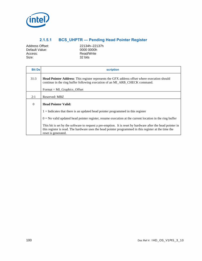
100 Doc Ref #: IHD_OS_V1Pt5_3_10
2.1.5.1 BCS_UHPTR — Pending Head Pointer Register Address Offset: 22134h–22137h Default Value: 0000 0000h Access: Read/Write Size: 32 bits
Bit De scription
31:3 Head Pointer Address: This register represents the GFX address offset where execution should continue in the ring buffer following execution of an MI_ARB_CHECK command.
Format = MI_Graphics_Offset
2:1 Reserved: MBZ
0 Head Pointer Valid:
1 = Indicates that there is an updated head pointer programmed in this register
0 = No valid updated head pointer register, resume execution at the current location in the ring buffer
This bit is set by the software to request a pre-emption. It is reset by hardware after the head pointer in this register is read. The hardware uses the head pointer programmed in this register at the time the reset is generated.
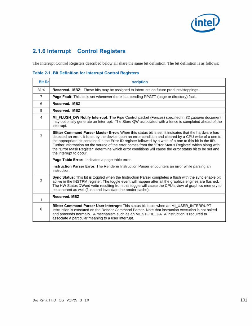
Doc Ref #: IHD_OS_V1Pt5_3_10 101
2.1.6 Interrupt Control Registers
The Interrupt Control Registers described below all share the same bit definition. The bit definition is as follows:
Table 2-1. Bit Definition for Interrupt Control Registers
Bit De scription
31:4 Reserved. MBZ: These bits may be assigned to interrupts on future products/steppings.
7 Page Fault: This bit is set whenever there is a pending PPGTT (page or directory) fault.
6 Reserved. MBZ
5 Reserved. MBZ
4 MI_FLUSH_DW Notify Interrupt: The Pipe Control packet (Fences) specified in 3D pipeline document may optionally generate an Interrupt. The Store QW associated with a fence is completed ahead of the interrupt.
3 Blitter Command Parser Master Error: When this status bit is set, it indicates that the hardware has detected an error. It is set by the device upon an error condition and cleared by a CPU write of a one to the appropriate bit contained in the Error ID register followed by a write of a one to this bit in the IIR. Further information on the source of the error comes from the “Error Status Register” which along with the “Error Mask Register” determine which error conditions will cause the error status bit to be set and the interrupt to occur.
Page Table Error: Indicates a page table error.
Instruction Parser Error: The Renderer Instruction Parser encounters an error while parsing an instruction.
2 Sync Status: This bit is toggled when the Instruction Parser completes a flush with the sync enable bit active in the INSTPM register. The toggle event will happen after all the graphics engines are flushed. The HW Status DWord write resulting from this toggle will cause the CPU’s view of graphics memory to be coherent as well (flush and invalidate the render cache).
1 Reserved. MBZ
0 Blitter Command Parser User Interrupt: This status bit is set when an MI_USER_INTERRUPT instruction is executed on the Render Command Parser. Note that instruction execution is not halted and proceeds normally. A mechanism such as an MI_STORE_DATA instruction is required to associate a particular meaning to a user interrupt.
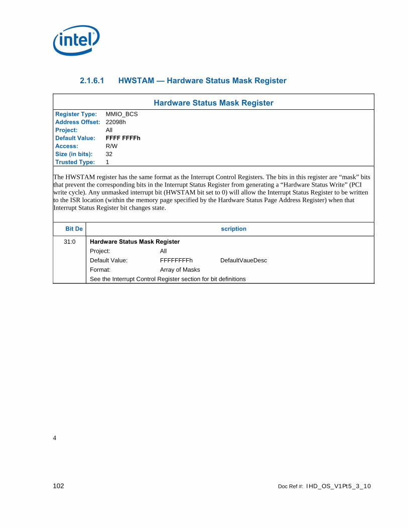
102 Doc Ref #: IHD_OS_V1Pt5_3_10
2.1.6.1 HWSTAM — Hardware Status Mask Register
Hardware Status Mask Register Register Type: MMIO_BCS Address Offset: 22098h Project: All Default Value: FFFF FFFFh Access: R/W Size (in bits): 32 Trusted Type: 1
The HWSTAM register has the same format as the Interrupt Control Registers. The bits in this register are “mask” bits that prevent the corresponding bits in the Interrupt Status Register from generating a “Hardware Status Write” (PCI write cycle). Any unmasked interrupt bit (HWSTAM bit set to 0) will allow the Interrupt Status Register to be written to the ISR location (within the memory page specified by the Hardware Status Page Address Register) when that Interrupt Status Register bit changes state.
Bit De scription
31:0 Hardware Status Mask Register Project: All Default Value: FFFFFFFFh DefaultVaueDesc Format: Array of Masks See the Interrupt Control Register section for bit definitions
4

Doc Ref #: IHD_OS_V1Pt5_3_10 103
2.1.6.2 IMR—Interrupt Mask Register
IMR—Interrupt Mask Register Register Type: MMIO_BCS Address Offset: 220A8h Project: All Default Value: FFFF FFFFh Access: R/W Size (in bits): 32 The IMR register is used by software to control which Interrupt Status Register bits are “masked” or “unmasked”. “Unmasked” bits will be reported in the IIR, possibly triggering a CPU interrupt, and will persist in the IIR until cleared by software. “Masked” bits will not be reported in the IIR and therefore cannot generate CPU interrupts.
Bit De scription
31:0 Interrupt Mask Bits Project: All Default Value: FFFF FFFFh Format: Array of interrupt
mask bits Refer to Table 1 4 in Interrupt Control Register section for bit definitions
This field contains a bit mask which selects which interrupt bits (from the ISR) are reported in the IIR. Value Na me Description Project
0h Not Masked Will be reported in the IIR All
1h Masked Will not be reported in the IIR All

104 Doc Ref #: IHD_OS_V1Pt5_3_10
2.1.6.3 Hardware-Detected Error Bit Definitions (for EIR, EMR, ESR)
This section defines the Hardware-Detected Error bit definitions and ordering that is common to the EIR, EMR and ESR registers. The EMR selects which error conditions (bits) in the ESR are reported in the EIR. Any bit set in the EIR will cause the Master Error bit in the ISR to be set. EIR bits will remain set until the appropriate bit(s) in the EIR is cleared by writing the appropriate EIR bits with ‘1’.
The following table describes the Hardware-Detected Error bits:
Table 2-2. Hardware-Detected Error Bits
Bit De scription
15:5 Reserved: MBZ
4 Page Table Error: This bit is set when a Graphics Memory Mapping Error is detected. The cause of the error is indicated (to some extent) in the PGTBL_ER register.
Note: This error indications can not be cleared except by reset (i.e., it is a fatal error).
1 = Page table error
1 Reserved.
0 Instruction Error: This bit is set when the Renderer Instruction Parser detects an error while parsing an instruction.
Instruction errors include:
1) Client ID value (Bits 31:29 of the Header) is not supported (only MI, 2D and 3D are supported).
2) Defeatured MI Instruction Opcodes:
1: Instruction Error detected
Programming Note:
[DevBW][DevCL]: The bit for the error mask of this register is reserved. The mask should be set to a value of 1.

Doc Ref #: IHD_OS_V1Pt5_3_10 105
2.1.6.3.1 EIR — Error Identity Register
EIR — Error Identity Register Register Type: MMIO_BCS Address Offset: 220B0h Project: All Default Value: 0000 0000h Access: R/WC Size (in bits): 32 The EIR register contains the persistent values of Hardware-Detected Error Condition bits. Any bit set in this register will cause the Master Error bit in the ISR to be set. The EIR register is also used by software to clear detected errors (by writing a ‘1’ to the appropriate bit(s)).
Bit De scription
31:16 Reserved Project: All Format: MBZ 15:0 Error Identity Bits
Project: All Default Value: 0h Format: Array of Error
condition bits See Table 1 5. Hardware-Detected Error Bits
This register contains the persistent values of ESR error status bits that are unmasked via the EMR register. The logical OR of all (defined) bits in this register is reported in the Master Error bit of the Interrupt Status Register. In order to clear an error condition, software must first clear the error by writing a ‘1’ to the appropriate bit(s) in this field. If required, software should then proceed to clear the Master Error bit of the IIR. Value Na me Description Project
1h Error occurred Error occurred All Programming Notes Project
Writing a ‘1’ to a set bit will cause that error condition to be cleared. However, the Page Table Error bit (Bit 4) can not be cleared except by reset (i.e., it is a fatal error).
All

106 Doc Ref #: IHD_OS_V1Pt5_3_10
2.1.6.3.2 EMR—Error Mask Register
EMR—Error Mask Register Register Type: MMIO_BCS Address Offset: 220B4h Project: All Default Value: FFFF FFFFh Access: R/W Size (in bits): 32 The EMR register is used by software to control which Error Status Register bits are “masked” or “unmasked”. “Unmasked” bits will be reported in the EIR, thus setting the Master Error ISR bit and possibly triggering a CPU interrupt, and will persist in the EIR until cleared by software. “Masked” bits will not be reported in the EIR and therefore cannot generate Master Error conditions or CPU interrupts.
Bit De scription
31:16 Reserved Project: All Format: MBZ 15:0 Error Mask Bits
Project: All Default Value: FFFF FFFFh Format: Array of error
condition mask bits See Table 1 5. Hardware-Detected Error Bits
This register contains a bit mask that selects which error condition bits (from the ESR) are reported in the EIR. Value Na me Description Project
0h Not Masked Will be reported in the EIR All
1h Masked Will not be reported in the EIR All

Doc Ref #: IHD_OS_V1Pt5_3_10 107
2.1.6.3.3 ESR—Error Status Register
ESR—Error Status Register Register Type: MMIO_BCS Address Offset: 220B8h Project: All Default Value: 0000 0000h Access: RO Size (in bits): 32 The ESR register contains the current values of all Hardware-Detected Error condition bits (these are all by definition “persistent”). The EMR register selects which of these error conditions are reported in the persistent EIR (i.e., set bits must be cleared by software) and thereby causing a Master Error interrupt condition to be reported in the ISR.
Bit De scription
31:16 Reserved Project: All Format: MBZ 15:0 Error Status Bits
Project: All Default Value: 0h Format: Array of error
condition bits See Table 1 5. Hardware-Detected Error Bits
This register contains the non-persistent values of all hardware-detected error condition bits. Value Na me Description Project
1h Error Condition Detected
Error Condition detected All

108 Doc Ref #: IHD_OS_V1Pt5_3_10
2.1.7 Logical Context Support
2.1.7.1 BCS_BB_ADDR—Batch Buffer Head Pointer Register Address Offset: 022140h–022147h Default Value: 0000 0000 0000 0000h Access: Read-Only Size: 64 bits
This register contains the current QWord Graphics Memory Address of the last-initiated batch buffer.
Bit De scription
63:32 Reserved: MBZ
31:3 Batch Buffer Head Pointer: This field specifies the QWord-aligned Graphics Memory Address where the last initiated Batch Buffer is currently fetching commands. If no batch buffer is currently active, the Valid bit will be 0 and this field will be meaningless. .
2:1 Reserved: MBZ
0 Valid:
1 = Batch buffer Valid
0 = Batch buffer Invalid

Doc Ref #: IHD_OS_V1Pt5_3_10 109
2.1.8 Software Control Bit Definitions
Registers in the range 22XX are not protected from the load register immediate instruction if the command is executed in the non-secure batch buffer.
2.2 Memory Interface Commands for Blitter Engine
2.2.1 Introduct ion
This chapter describes the formats of the “Memory Interface” commands, including brief descriptions of their use. The functions performed by these commands are discussed fully in the Memory Interface Functions Device Programming Environment chapter.
This chapter describes MI Commands for the blitter graphics processing engine. The term “for Blitter Engine” in the title has been added to differentiate this chapter from a similar one describing the MI commands for the Media Decode Engine and the Rendering Engine.
The commands detailed in this chapter are used across products within the Gen4 family. However, slight changes may be present in some commands (i.e., for features added or removed), or some commands may be removed entirely. Refer to the Preface chapter for product specific summary.
2.2.2 MI_ARB_CHECK
The MI_ARB_CHECK instruction is used to check the ring buffer next context ID register (RNCID) or the UHPTR register. This instruction can be used to pre-empt the current execution of the ring buffer. Note that the valid bit in the RNCID register or the UHPTR register needs to be set for the command streamer to be pre-empted.
Programming Note:
• This instruction can be placed only in a ring buffer, never in a batch buffer.
The instruction format is:
DWord Bits Description
31:29 Instruction Type = MI_INSTRUCTION = 0h
28:23 MI Instruction Opcode = MI_ARB_CHECK = 05h
0
22:0 Reserved: MBZ

110 Doc Ref #: IHD_OS_V1Pt5_3_10
2.2.3 MI_SUSPEND_FLUSH
MI_SUSPEND_FLUSH Project: All Length Bias: 1 Blocks MMIO sync flush or any flushes related to VT-d while enabled.
DWord Bit Description
0 31:29 Command Type Default Value: 0h MI_COMMAND Format: OpCode
28:23 MI Command Opcode Default Value: 0Bh MI_SUSPEND_FLUSH Format: OpCode
22:1 Reserved Project: All Format: MBZ 0 Suspend Flush
Project: All Default Value: 0h DefaultVaueDesc Format: Enable FormatDesc This field suspends flush due to sync flush or implicit flush generated during VTD enable, disable and IOTLB invalidation. Value Na me Description Project
0h Disable All
1h Enable All