intel raid expander card res3fv288 · intel® raid expander card res3fv288 . hardware user's...
TRANSCRIPT
Intel® RAID Expander Card RES3FV288 Hardware User's Guide
Intel Order Number: H34798-004
Rev 2.0 January 2016
Intel Server Boards and Systems

<This page is intentionally left blank.>

Intel® RAID Expander Card RES3FV288 Hardware User’s Guide
i
Document Revision History Date Published Revision Revision Change Description Jun 2014 1.0 Production version. Jan 2016 2.0 • Applied to the new format.
• Corrected the SAS connector description • Corrected verbiage about wide ports • Removed reference to activity and fault indicators

Intel® RAID Expander Card RES3FV288 Hardware User’s Guide
ii
DISCLAIMER No license (express or implied, by estoppel or otherwise) to any intellectual property rights is granted by this document. Intel disclaims all express and implied warranties, including without limitation, the implied warranties of merchantability, fitness for a particular purpose, and non-infringement, as well as any warranty arising from course of performance, course of dealing, or usage in trade. This document contains information on products, services and/or processes in development. All information provided here is subject to change without notice. Contact your Intel representative to obtain the Hardware Users Guide. The products and services described may contain defects or errors known as errata which may cause deviations from published specifications. Current characterized errata are available on request. Intel, the Intel logo, are trademarks of Intel Corporation in the U.S. and/or other countries. *Other names and brands may be claimed as the property of others © 2016 Intel Corporation
Intel® RAID Expander Card RES3FV288 Hardware User’s Guide
iii
Intel Use only with the listed ITE:
RES3FV288
Regulatory Compliance Statements
Federal Communications Commission Radio Frequency Interference Statement
Attention: Changes or modifications to this unit not expressly approved by the party responsible for compliance could void the user’s authority to operate the equipment. This equipment has been tested and found to comply with the limits for a Class B digital device, pursuant to Part 15 of the FCC rules. These limits are designed to provide reasonable protection against harmful interference in a residential installation. This equipment generates, uses, and can radiate radio frequency energy, and if not installed and used in accordance with the instruction manual, may cause harmful interference to radio communications. However, there is no guarantee that interference will not occur in a particular installation. However, if this equipment does cause interference to radio or television equipment reception, which can be determined by turning the equipment off and on, the user is encouraged to try to correct the interference by one or more of the following measures: • Reorient or relocate the receiving antenna. • Increase the separation between equipment and receiver. • Connect the equipment to an outlet on a circuit different from that to which the receiver is connected. • Consult the dealer or an experienced radio/television technician for help. • Use a shielded and properly grounded I/O cable and power cable to ensure compliance of this unit to the
specified limits of the rules. This device complies with part 15 of the FCC rules. Operation is subject to the following two conditions: (1) this device may not cause harmful interference and (2) this device must accept any interference received, including interference that may cause undesired operation.
UL Compliance Statement
Intel® products are tested and listed by Underwriters Laboratories, Inc. to UL 60950-1 Second Edition and IEC-60950-1 Second Edition standards, file numbers E175975.
These products are for use only with UL listed ITE.
Special International Committee on Radio Interference Compliance Statement
(CISPR 22)
This product has been found to comply with the requirements of the Information Technology Equipment -- Radio Disturbance Characteristics -- Limits and Methods of Measurement (CISPR 22).
Intel® RAID Expander Card RES3FV288 Hardware User’s Guide
iv
European Union Compliance Statement
This Information Technology Equipment has been tested and found to comply with EMC Directive 89/336/EEC, as amended by 92/31/EEC and 93/68/EEC, in accordance with:
• EN55022 (1998+A1:2000+A2:2007) Emissions: - Class B ITE radiated and conducted emissions
• EN55024 (1998+A1:2001+A2:2010) Immunity: - EN61000-4-2 (2009) Electrostatic discharge: ±4 kV contact, ±8 kV air - EN61000-4-3 (2010) Radiated immunity: 3V/m - EN61000-4-4 (2004) Electrical fast transients/burst: ±1 kV AC, ±0.5 kV I/O - EN61000-4-5 (2006) Surges: ±1 kV differential mode, ±2 kV common mode - EN61000-4-6 (2009) Conducted immunity: 3 V - EN61000-4-11 (2004) Supply dips and variations: 30% and 100%
• EN50581 (2012) Technical Documentation: - For the assessment of electrical and electronic products with respect to the restriction of hazardous
substances In addition, all equipment requiring U.L. listing has been found to comply with EMC Directive 73/23/EEC as amended by 93/68/EEC in accordance with EN60950 with amendments A1, A2, A3, A4, A11.
Australian/New Zealand Compliance Statement
This device has been tested and found to comply with the limits for a Class B digital device, pursuant to the Australian/New Zealand standard AS/NZS 3548 set out by the Spectrum Management Agency.
Canadian Compliance Statement
This Class B digital apparatus meets all requirements of the Canadian Interference- Causing Equipment Regulations (ICES-003).
Cet appareil numérique de la classe B respecte toutes les exigences du Règlement sur le matériel brouilleur du Canada (ICES-003).
Japanese Compliance (Voluntary Control Council Initiative)
This equipment complies to class B Information Technology equipment based on VCCI (Voluntary Control Council for Interface). This equipment is designed for home use but it may causes radio frequency interference problem if used too near to a television or radio. Please handle it correctly per this documentation.
Korean Compliance (KCC) Statement
Intel® products are tested and certified by KCC: RES3FV288
Intel® RAID Expander Card RES3FV288 Hardware User’s Guide
v
This equipment is home use (Class B) electromagnetic wave suitability equipment and to be used mainly at home and it can be used in all areas.
Taiwan Compliance
This equipment complies to class B Information Technology equipment based on VCCI (Voluntary Control Council for Interface). This equipment is designed for home use but it may causes radio frequency interference
problem if used too near to a television or radio. Please handle it correctly per this documentation.
Intel® RAID Expander Card RES3FV288 Hardware User’s Guide
vi
Table of Contents Regulatory Compliance Statements .................................................................................................................................................... iii
1 About This Guide ..................................................................................................................................................................................................1 1.1 What You Need to Know Before You Begin .................................................................................................................................1 1.2 Terminology Used in this Guide ......................................................................................................................................................1
2 Kit Contents and System Requirements ....................................................................................................................................................2 2.1 Kit Contents ............................................................................................................................................................................................2 2.2 System Requirements .........................................................................................................................................................................2
3 About Your RAID Expander ..............................................................................................................................................................................3 3.1 Standard RAID Expander Features..................................................................................................................................................3 3.2 Major Components ..............................................................................................................................................................................3 3.3 Compatible Devices .............................................................................................................................................................................5 3.4 Block Diagram ........................................................................................................................................................................................5 3.5 Board Dimensions ...............................................................................................................................................................................6 3.6 Mechanical Information ....................................................................................................................................................................6 3.7 About the Intel®
RAID Expander Card RES3FV288 ...............................................................................................................7
4 Installing and Connecting the RAID Expander ........................................................................................................................................8 4.1 Before You Begin ...................................................................................................................................................................................8 4.2 Replacing the Full-Height Bracket with a Low- Profile Bracket ..........................................................................................8 4.3 Selecting Disk Drives and Cables ................................................................................................................................................ 10
4.3.1 Disk Drives ............................................................................................................................................................................ 10 4.3.2 Cables ..................................................................................................................................................................................... 10 4.3.3 SAS Connectors .................................................................................................................................................................. 11
4.4 Installing the RAID Expander ........................................................................................................................................................ 12 5 Configuring the RAID Expander .................................................................................................................................................................. 14 6 Solving Problems .............................................................................................................................................................................................. 15
6.1 Troubleshooting Checklist ............................................................................................................................................................. 15 Appendix A: Safety Information ....................................................................................................................................................................... 16
Electrostatic Discharge (ESD) ........................................................................................................................................................................ 16 Appendix B: Technical Specifications ............................................................................................................................................................. 17
Environmental Specifications ........................................................................................................................................................................ 17 DC Power Requirements .................................................................................................................................................................................. 17 Current Requirements ...................................................................................................................................................................................... 17
Intel® RAID Expander Card RES3FV288 Hardware User’s Guide
1
1 About This Guide
This Installation and User's Guide explains how to install and configure your RAID Expander RES3FV288 in a RAID system.
1.1 What You Need to Know Before You Begin
You should be familiar with computer hardware, data storage, and Serial Attached SCSI (SAS) and Serial ATA (SATA) technology. You should also be familiar with RAID controllers, modules, expanders, and related support devices.
1.2 Terminology Used in this Guide
Many of the terms and concepts referred to in this guide are known to computer users by multiple names. This guide uses these terms: • Expander Card (also known as adapter, board, or I/O card) • Disk drive (also known as hard disk, hard drive, or hard disk drive) • Solid State Drive (also known as SSD or non-rotating storage media) • Enclosure (also known as storage enclosure, JBOD enclosure, or expander)
Intel® RAID Expander Card RES3FV288 Hardware User’s Guide
2
2 Kit Contents and System Requirements
This section lists the contents of your kit and the system requirements for successfully installing and using your expander card.
2.1 Kit Contents
• RAID Expander • Low-profile bracket • Cables to connect to HBA
2.2 System Requirements
• An Intel® Server Board based on the Intel® Xeon® processor E5-2600 v3 product family • Available compatible PCI Express* x4 connector or available RA 4-pin power connector • SAS or SATA hard drives allowing bandwidths up to 12 Gb/s • Full height or low profile brackets
Intel® RAID Expander Card RES3FV288 Hardware User’s Guide
3
3 About Your RAID Expander
This section provides an overview of the features of your RAID Expander.
3.1 Standard RAID Expander Features
• Support for both SAS and SATA devices • Data transfer rate of 12 Gb/s, 6 Gb/s, 3 Gb/s, or 1.5 Gb/s • Seven SFF-8643 mini-SAS-HD internal and two external SFF-8644 connectors providing 36 SAS/SATA ports • Support for the configuration of up to 8 inputs and 28 outputs • Output mini-SAS connectors supporting sideband SGPIO per the SFF-8485 specification • Power from a standard PCI Express* x4 connector or RA 4-pin power connector • Board functioning either in PCI Express slot or remotely in system • On-board screw holes allowing the expander card to be mounted on a chassis wall inside a server system • Low profile and MD2 compliance • Provides a low-latency connection to create and maintain transparent access to each connected SAS/SATA
physical drive. • Staggered spin-up • Native Command Queuing • Allows multiple initiators to address a single target. • Supports cascaded expander products. • Each port on the expander card supports SAS devices, SATA II devices, or both using SSP, SMP, and STP:
- Serial SCSI Protocol (SSP) to enable communication with other SAS devices - Serial Management Protocol (SMP) to share topology management information with expanders - Serial Tunneling Protocol (STP) support for SATA II through expander interfaces - SAS protocol, described in the Serial Attached SCSI (SAS) Standard, version 2.0 - SFF-8485 protocol, using the Serial GPIO (SGPIO) interface provided by the expander
• Enclosure Management - On-board temperature sensor - SGPIO
3.2 Major Components
• 36-Port 12 Gb/s SAS-3 Expander Chip - Provides 36 PHYs.
Any input PHYs may be combined into wide port(s). Any output PHY can be SAS or SATA attached.
- Supports multiple data rates and auto-negotiation between the following: 3.0 Gb/s, 6.0 Gb/s, and 12.0 Gb/s SAS 3.0 Gb/s and 6.0 Gb/s SATA
- Supports SSP, STP, and SMP. - Supports the SAS protocol described in the Serial Attached SCSI (SAS) Standard, version 3.0r5. - Provides a low-latency connection router to efficiently create and maintain connections. - Supports T10-Based and PHY-Based Zoning for storage partitioning. - Provides up to 12 I2C interfaces.
• Flash ROM – A 128-Mbit Quad SPI flash ROM is used to accommodate expander card firmware. • Heartbeat LED – A green LED provides a heartbeat with a 1 second blink rate to indicate the expander has booted
properly. SAS connectors – The RES3FV288 RAID Expander provides internal and external SAS connectors as shown in Section 0

Intel® RAID Expander Card RES3FV288 Hardware User’s Guide
4
Intel® RAID Expander Card RES3FV288 Hardware User’s Guide
5
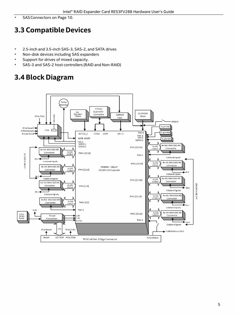
• SAS Connectors on Page 10.
3.3 Compatible Devices
• 2.5-inch and 3.5-inch SAS-3, SAS-2, and SATA drives • Non-disk devices including SAS expanders • Support for drives of mixed capacity. • SAS-3 and SAS-2 host controllers (RAID and Non-RAID)
3.4 Block Diagram
Intel® RAID Expander Card RES3FV288 Hardware User’s Guide
6
3.5 Board Dimensions
The table below lists the board dimensions of your RAID Expander RES3FV288. Dimension RAID Expander RES3FV288
Height 2.535”
Length 6.00”
PCB Thickness 0.062”
Max Component Height, Top Side 0.570”
Max Component Height, Bottom Side 0.105”
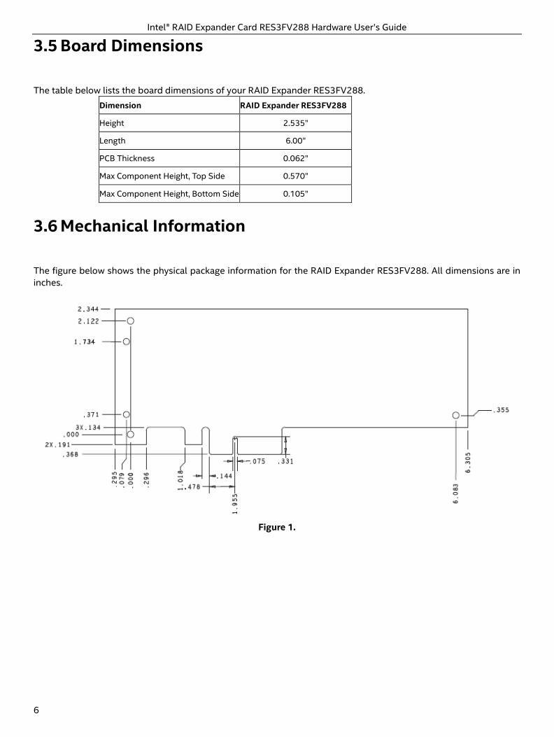
3.6 Mechanical Information
The figure below shows the physical package information for the RAID Expander RES3FV288. All dimensions are in inches.
Figure 1.
Intel® RAID Expander Card RES3FV288 Hardware User’s Guide
7
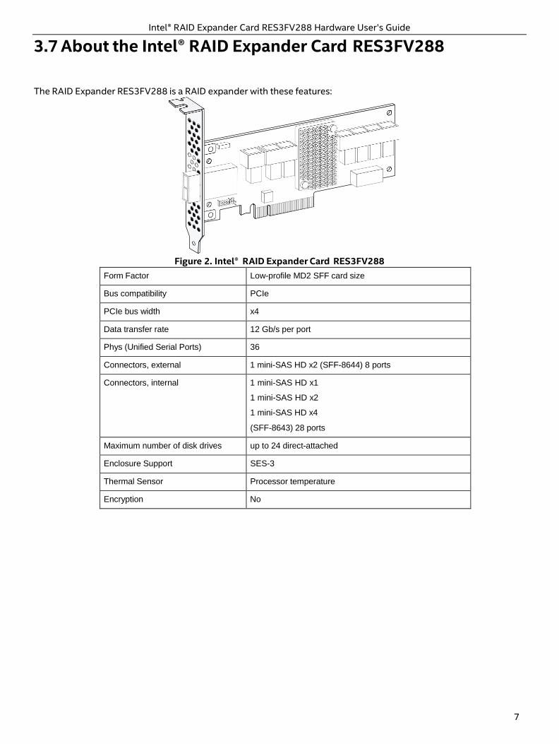
3.7 About the Intel® RAID Expander Card RES3FV288
The RAID Expander RES3FV288 is a RAID expander with these features:
Figure 2. Intel®
RAID Expander Card RES3FV288
Form Factor Low-profile MD2 SFF card size
Bus compatibility PCIe
PCIe bus width x4
Data transfer rate 12 Gb/s per port
Phys (Unified Serial Ports) 36
Connectors, external 1 mini-SAS HD x2 (SFF-8644) 8 ports
Connectors, internal 1 mini-SAS HD x1
1 mini-SAS HD x2
1 mini-SAS HD x4
(SFF-8643) 28 ports
Maximum number of disk drives up to 24 direct-attached
Enclosure Support SES-3
Thermal Sensor Processor temperature
Encryption No
Intel® RAID Expander Card RES3FV288 Hardware User’s Guide
8
4 Installing and Connecting the RAID Expander
This section explains how to install your RAID Expander and connect it to internal and external disk drives.
4.1 Before You Begin
• Read Appendix A: Safety Information. • Familiarize yourself with your product's physical features (see Section 3.1 Standard RAID Expander Features on
Page 3). • Ensure that you have the right number of drives and cables for your application (see Section 4.3 Selecting Disk
Drives and Cables on Page 9).
4.2 Replacing the Full-Height Bracket with a Low- Profile
Bracket
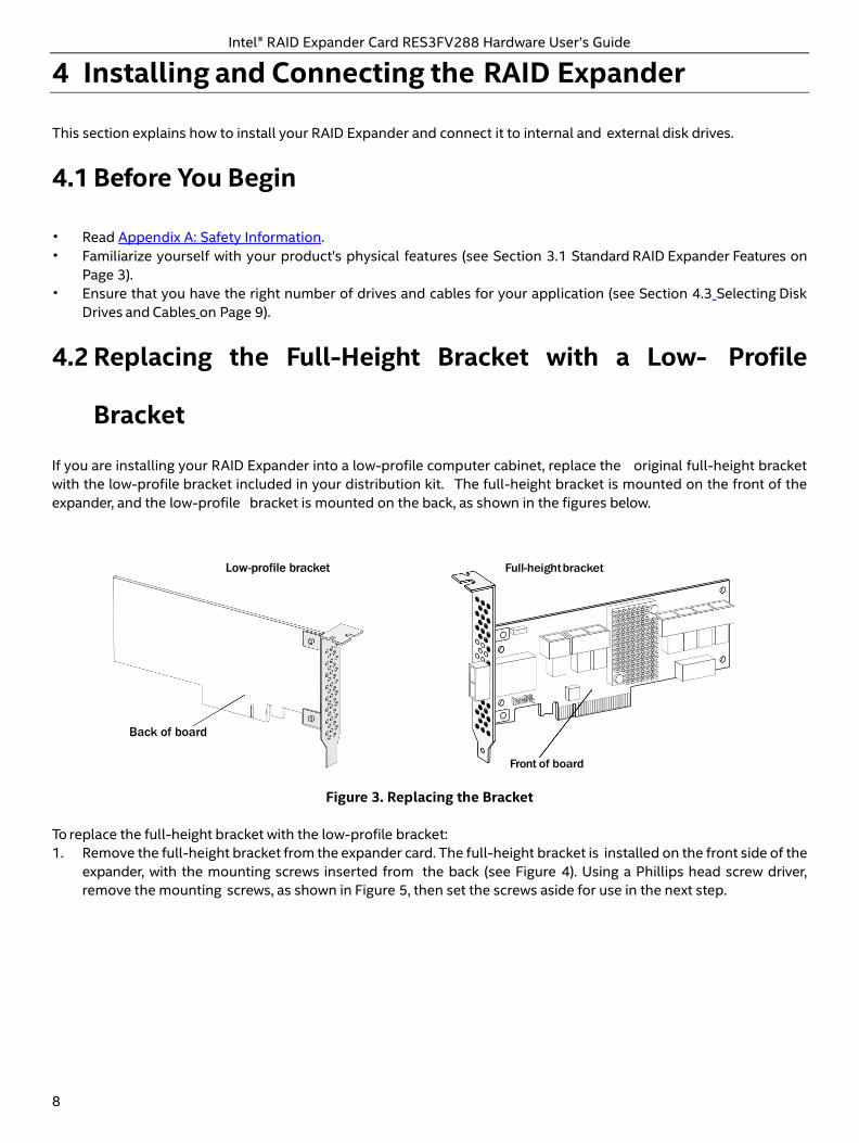
If you are installing your RAID Expander into a low-profile computer cabinet, replace the original full-height bracket with the low-profile bracket included in your distribution kit. The full-height bracket is mounted on the front of the expander, and the low-profile bracket is mounted on the back, as shown in the figures below.
Low-profile bracket
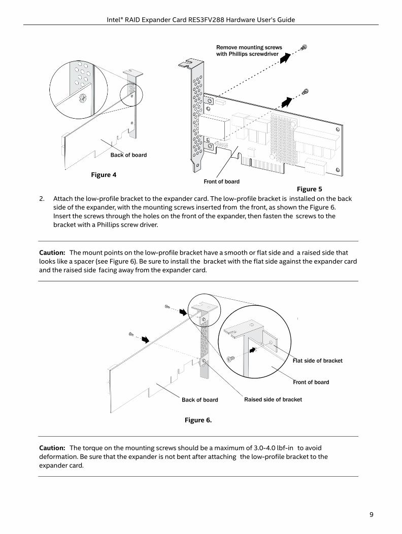
Figure 3. Replacing the Bracket To replace the full-height bracket with the low-profile bracket: 1. Remove the full-height bracket from the expander card. The full-height bracket is installed on the front side of the
expander, with the mounting screws inserted from the back (see Figure 4). Using a Phillips head screw driver, remove the mounting screws, as shown in Figure 5, then set the screws aside for use in the next step.
Back of board
Intel® RAID Expander Card RES3FV288 Hardware User’s Guide
9
Back of board Raised side of bracket
Back of board
Figure 4
Front of board
Figure 5 2. Attach the low-profile bracket to the expander card. The low-profile bracket is installed on the back
side of the expander, with the mounting screws inserted from the front, as shown the Figure 6. Insert the screws through the holes on the front of the expander, then fasten the screws to the bracket with a Phillips screw driver.
Caution: The mount points on the low-profile bracket have a smooth or flat side and a raised side that looks like a spacer (see Figure 6). Be sure to install the bracket with the flat side against the expander card and the raised side facing away from the expander card.
Flat side of bracket
Front of board
Figure 6.
Caution: The torque on the mounting screws should be a maximum of 3.0-4.0 lbf-in to avoid deformation. Be sure that the expander is not bent after attaching the low-profile bracket to the expander card.
Remove mounting screws with Phillips screwdriver
10 Intel® RAID Expander Card RES3FV288 Hardware User’s Guide
Intel® RAID Expander Card RES3FV288 Hardware User’s Guide
4.3 Selecting Disk Drives and Cables
4.3.1 Disk Drives
Your RAID Expander supports SAS and SATA disk drives, Solid State Drives (SSDs), and SAS tape drives.
4.3.2 Cables
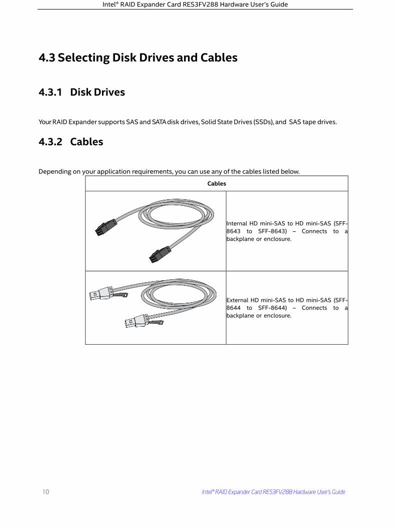
Depending on your application requirements, you can use any of the cables listed below.
Cables
Internal HD mini-SAS to HD mini-SAS (SFF-8643 to SFF-8643) – Connects to a backplane or enclosure.
External HD mini-SAS to HD mini-SAS (SFF-8644 to SFF-8644) – Connects to a backplane or enclosure.
Intel® RAID Expander Card RES3FV288 Hardware User’s Guide 9
Intel® RAID Expander Card RES3FV288 Hardware User’s Guide
4.3.3 SAS Connectors
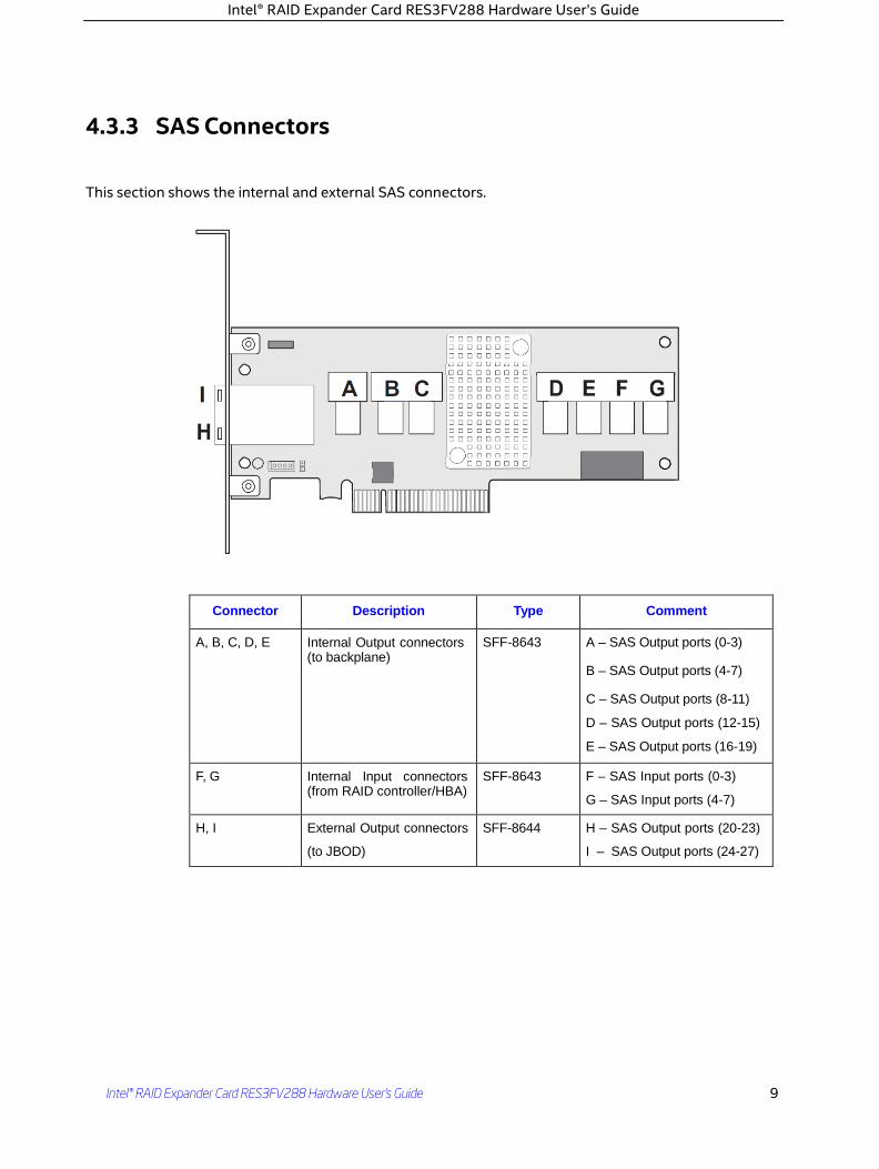
This section shows the internal and external SAS connectors.
Connector Description Type Comment
A, B, C, D, E Internal Output connectors (to backplane)
SFF-8643 A – SAS Output ports (0-3)
B – SAS Output ports (4-7)
C – SAS Output ports (8-11)
D – SAS Output ports (12-15)
E – SAS Output ports (16-19)
F, G Internal Input connectors (from RAID controller/HBA)
SFF-8643 F – SAS Input ports (0-3)
G – SAS Input ports (4-7)
H, I External Output connectors
(to JBOD)
SFF-8644 H – SAS Output ports (20-23)
I – SAS Output ports (24-27)
Intel® RAID Expander Card RES3FV288 Hardware User’s Guide
12
4.4 Installing the RAID Expander
This section describes how to install the RAID Expander into your computer cabinet or server. The RAID Expander comes in two configurations: • Expanders with internal connectivity • Expanders with external connectivity Follow the steps below to install your RAID Expander card and connect your internal or external storage devices.
Caution: Be sure to handle the expander by its bracket or edges only.
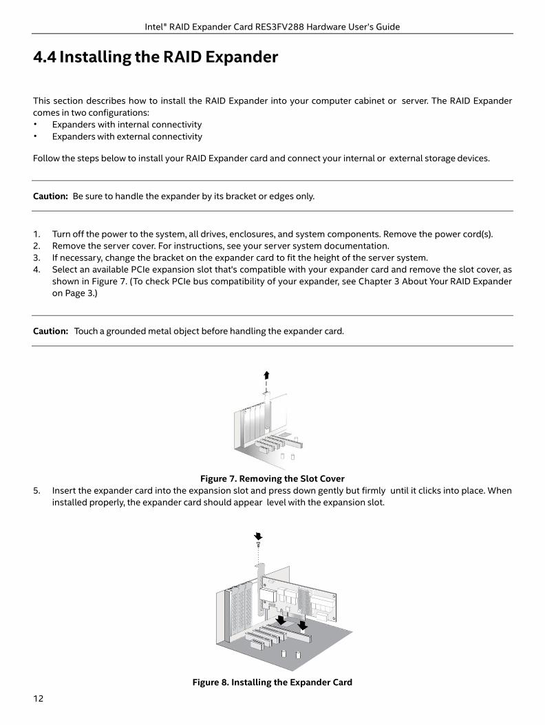
1. Turn off the power to the system, all drives, enclosures, and system components. Remove the power cord(s). 2. Remove the server cover. For instructions, see your server system documentation. 3. If necessary, change the bracket on the expander card to fit the height of the server system. 4. Select an available PCIe expansion slot that's compatible with your expander card and remove the slot cover, as
shown in Figure 7. (To check PCIe bus compatibility of your expander, see Chapter 3 About Your RAID Expander on Page 3.)
Caution: Touch a grounded metal object before handling the expander card.
Figure 7. Removing the Slot Cover
5. Insert the expander card into the expansion slot and press down gently but firmly until it clicks into place. When installed properly, the expander card should appear level with the expansion slot.
Figure 8. Installing the Expander Card
Intel® RAID Expander Card RES3FV288 Hardware User’s Guide
13
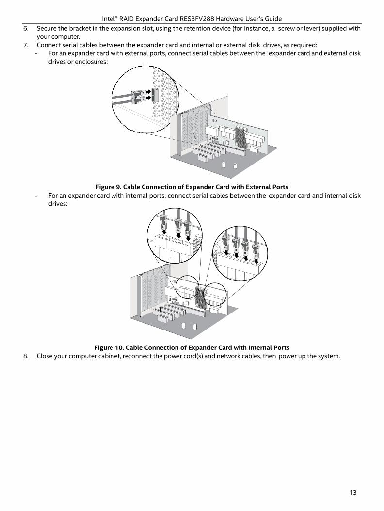
6. Secure the bracket in the expansion slot, using the retention device (for instance, a screw or lever) supplied with your computer.
7. Connect serial cables between the expander card and internal or external disk drives, as required: - For an expander card with external ports, connect serial cables between the expander card and external disk
drives or enclosures:
Figure 9. Cable Connection of Expander Card with External Ports
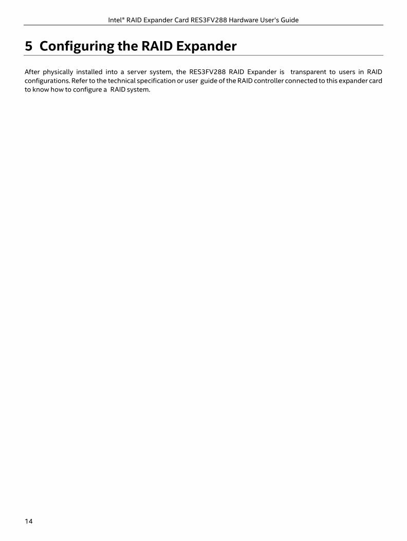
- For an expander card with internal ports, connect serial cables between the expander card and internal disk drives:
Figure 10. Cable Connection of Expander Card with Internal Ports
8. Close your computer cabinet, reconnect the power cord(s) and network cables, then power up the system.
Intel® RAID Expander Card RES3FV288 Hardware User’s Guide
14
5 Configuring the RAID Expander
After physically installed into a server system, the RES3FV288 RAID Expander is transparent to users in RAID configurations. Refer to the technical specification or user guide of the RAID controller connected to this expander card to know how to configure a RAID system.
Intel® RAID Expander Card RES3FV288 Hardware User’s Guide
15
6 Solving Problems
This section provides basic troubleshooting information and solutions for solving problems with your RAID Expander.
6.1 Troubleshooting Checklist
If you encounter difficulties installing or using your RAID Expander, check these items first: • Ensure that your expander is connected to a RAID controller correctly, check the input and output ports on page 10. • With your computer powered off, check the connections to each disk drive, power supply, LED connector, and so
on. • Try disconnecting and reconnecting disk drives from the expander. • Check that your expander is installed in a compatible PCIe expansion slot. To double-check the bus compatibility
of your expander, see Chapter 3 About Your RAID Expander on Page 3. • Ensure that your expander is firmly seated and secured in the PCIe expansion slot. • If your expander is not detected during system boot, try installing it in a different compatible expansion slot. (See
Section 4.4 Installing the RAID Expander on Page 12 for instructions.) • If you have external disk drives (or other devices), are they powered on and working?
Intel® RAID Expander Card RES3FV288 Hardware User’s Guide
16
Appendix A: Safety Information
To ensure your personal safety and the safety of your equipment: • Keep your work area and the computer clean and clear of debris. • Before opening the system cabinet, unplug the power cord(s).
Electrostatic Discharge (ESD)
Caution: ESD can damage electronic components when they are improperly handled, and can result in total or intermittent failures. Always follow ESD-prevention procedures when removing and replacing components.
To prevent ESD damage: • Use an ESD wrist or ankle strap and ensure that it makes skin contact. Connect the equipment end of the strap to
an unpainted metal surface on the chassis. • Avoid touching the expander against your clothing. The wrist strap protects components from ESD on the body
only. • Handle the expander by its bracket or edges only. Avoid touching the printed circuit board or the connectors. • Put the expander down only on an anti-static surface such as the bag supplied in your kit. If a wrist strap is not available, ground yourself by touching the metal chassis before handling the expander or any other part of the computer.
Intel® RAID Expander Card RES3FV288 Hardware User’s Guide
17
Appendix B: Technical Specifications
Environmental Specifications
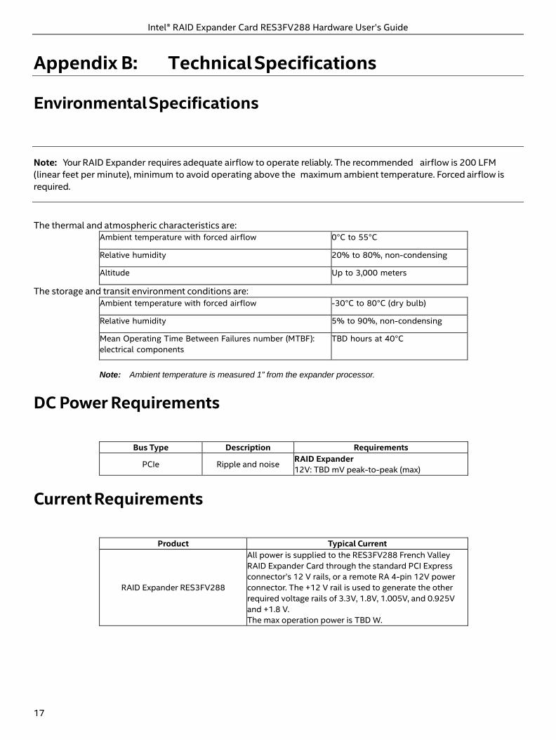
Note: Your RAID Expander requires adequate airflow to operate reliably. The recommended airflow is 200 LFM (linear feet per minute), minimum to avoid operating above the maximum ambient temperature. Forced airflow is required.
The thermal and atmospheric characteristics are: Ambient temperature with forced airflow 0°C to 55°C
Relative humidity 20% to 80%, non-condensing
Altitude Up to 3,000 meters
The storage and transit environment conditions are: Ambient temperature with forced airflow -30°C to 80°C (dry bulb)
Relative humidity 5% to 90%, non-condensing
Mean Operating Time Between Failures number (MTBF): electrical components
TBD hours at 40°C
Note: Ambient temperature is measured 1” from the expander processor.
DC Power Requirements
Bus Type Description Requirements
PCIe Ripple and noise RAID Expander 12V: TBD mV peak-to-peak (max)
Current Requirements
Product Typical Current
RAID Expander RES3FV288
All power is supplied to the RES3FV288 French Valley RAID Expander Card through the standard PCI Express connector’s 12 V rails, or a remote RA 4-pin 12V power connector. The +12 V rail is used to generate the other required voltage rails of 3.3V, 1.8V, 1.005V, and 0.925V and +1.8 V. The max operation power is TBD W.