intel true scale fabric switches 12000 series...intel® true scale fabric switches 12000 series july...
TRANSCRIPT

Doc. Number: G91930 Revision: 005US
Intel® True Scale Fabric Switches 12000 SeriesUser Guide
July 2015

Intel® True Scale Fabric Switches 12000 SeriesUser Guide July 20152 Doc. Number: G91930 Revision: 005US
No license (express or implied, by estoppel or otherwise) to any intellectual property rights is granted by this document.Intel disclaims all express and implied warranties, including without limitation, the implied warranties of merchantability, fitness for a particular purpose, and non-infringement, as well as any warranty arising from course of performance, course of dealing, or usage in trade.This document contains information on products, services and/or processes in development. All information provided here is subject to change without notice. Contact your Intel representative to obtain the latest forecast, schedule, specifications and roadmaps.The products and services described may contain defects or errors which may cause deviations from published specifications. You may not use or facilitate the use of this document in connection with any infringement or other legal analysis concerning Intel products described herein. You agree to grant Intel a non-exclusive, royalty-free license to any patent claim thereafter drafted which includes subject matter disclosed herein.Copies of documents which have an order number and are referenced in this document, or other Intel literature, may be obtained by calling 1-800-548-4725, or by visiting: http://www.intel.com/design/literature.htm Intel and the Intel logo are trademarks of Intel Corporation in the U.S. and/or other countries.*Other names and brands may be claimed as the property of others.Copyright © 2015, Intel Corporation. All rights reserved.

Intel® True Scale Fabric Switches 12000 SeriesJuly 2015 User GuideDoc. Number: G91930 Revision: 005US 3
Contents
1.0 Introduction ..............................................................................................................91.1 Intended Audience.............................................................................................91.2 Related Materials...............................................................................................91.3 Documentation Conventions................................................................................91.4 Laser Safety Information .................................................................................. 101.5 Electrostatic Discharge Sensitivity (ESDS) Precautions.......................................... 101.6 License Agreements......................................................................................... 101.7 Technical Support............................................................................................ 11
2.0 Chassis Viewer Overview......................................................................................... 132.1 Home Page..................................................................................................... 132.2 Displaying the Chassis View .............................................................................. 14
2.2.1 Leaf Module View ............................................................................. 142.2.2 Management Module View ............................................................... 152.2.3 Home Page Toolbar .......................................................................... 16
2.3 Displaying the Leaf, Spine, and Management Module Views................................... 162.3.1 Leaf Module View................................................................................ 162.3.2 Spine Module View .............................................................................. 172.3.3 Management Module View.................................................................... 17
2.4 Component Details Area ................................................................................... 182.4.1 Details Header.................................................................................... 182.4.2 Module Information Area...................................................................... 192.4.3 Chassis View Component Information Area............................................. 192.4.4 Modifying Switch Component Information............................................... 202.4.5 Chassis View Component Information Area Tabs ..................................... 21
3.0 Configuration and Monitoring .................................................................................. 253.1 Chassis View Menu .......................................................................................... 253.2 Logging.......................................................................................................... 25
3.2.1 Set Level ........................................................................................... 263.2.2 Reset Log Levels................................................................................. 30
3.3 Maintenance ................................................................................................... 313.3.1 Firmware Update ................................................................................ 313.3.2 LDAP Configuration ............................................................................. 323.3.3 HTTP/CLI Session Configuration ............................................................ 33
3.4 SNMP............................................................................................................. 353.4.1 Target Configuration ........................................................................... 363.4.2 Filter Status ....................................................................................... 393.4.3 Set Community Strings........................................................................ 40
3.5 Configuration File Administration ....................................................................... 413.5.1 Administer ......................................................................................... 423.5.2 Host Upload/Download ........................................................................ 433.5.3 Trap Control....................................................................................... 443.5.4 Subnet Manager Configuration File ........................................................ 46
3.6 Chassis Traps.................................................................................................. 473.7 Port Statistics ................................................................................................. 50
3.7.1 Understanding Port Naming Conventions................................................ 503.7.2 Port Statistics Field Descriptions............................................................ 513.7.3 IB Statistics Field Descriptions .............................................................. 523.7.4 Leaf and Spine Module IB Port Statistics................................................. 533.7.5 Set Field Thresholds ............................................................................ 553.7.6 Port Beacon ....................................................................................... 57

Intel® True Scale Fabric Switches 12000 SeriesUser Guide July 20154 Doc. Number: G91930 Revision: 005US
3.8 Time Service ...................................................................................................593.9 OOB LAN IP Submenu ......................................................................................62
3.9.1 Configuring the Switch OOB IP Address ..................................................623.9.2 Configuring the Switch Default Gateway IP Address .................................64
3.10 Fabric Manager Configuration ............................................................................653.10.1 Automatically starting the Fabric Manager...............................................65
3.11 Management Module Menu................................................................................663.11.1 Logging..............................................................................................663.11.2 Viewing the Log ..................................................................................663.11.3 Purging the Log...................................................................................673.11.4 Select Boot Image ...............................................................................683.11.5 Post Diagnostics..................................................................................69
3.12 Fabric Manager Control .....................................................................................703.12.1 Accessing the Subnet Manager Control Window .......................................70
3.13 License Keys; Key Administration.......................................................................723.13.1 Adding a New License Key ....................................................................723.13.2 Deleting a License Key .........................................................................72
Figures1 User Authentication ..............................................................................................132 Intel® 12300 Home Page ......................................................................................143 Intel® 12800-040 Home Page................................................................................144 Help Button.........................................................................................................145 Leaf Module View Mouseover .................................................................................156 Management Module View Mouseover .....................................................................157 12800-040 Chassis View .......................................................................................168 Leaf Module Mouseover.........................................................................................169 Leaf Module View .................................................................................................1710 Spine Module Mouseover.......................................................................................1711 Spine Module View ...............................................................................................1712 Management Module Mouseover.............................................................................1813 Management Module View .....................................................................................1814 Component Details Area........................................................................................1815 Details Header .....................................................................................................1916 Module Information Area.......................................................................................1917 Chassis View Component Information Area ..............................................................2018 Reboot Window....................................................................................................2019 Reboot Window....................................................................................................2120 Chassis View Component Information Area, Showing LEDs and Sensors Tab.................2221 Chassis View Menu ...............................................................................................2522 Logging Submenu ................................................................................................2623 Set Level Button ..................................................................................................2624 Log System Configurator: Device Tab .....................................................................2625 Device Tab: Software Module Configurator ..............................................................2726 Log System Configurator: Preset Tab ......................................................................2927 Log System Configurator: Syslog Host Tab ..............................................................3028 Reset Levels Button..............................................................................................3029 Reset Log Levels Window ......................................................................................3130 Maintenance Menu ...............................................................................................3131 Firmware Update Button .......................................................................................3232 Firmware Update Window......................................................................................3233 LDAP Configuration Button ....................................................................................3334 LDAP Authentication Window .................................................................................33

Intel® True Scale Fabric Switches 12000 SeriesJuly 2015 User GuideDoc. Number: G91930 Revision: 005US 5
35 HTTP/CLI Session Config Button ............................................................................ 3436 HTTP/CLI Session Configuration Window ................................................................. 3437 User Authentication Dropdown List......................................................................... 3438 HTTP Mode Dropdown List..................................................................................... 3539 HTTPs Mode Dropdown List ................................................................................... 3540 SNMP Submenu................................................................................................... 3641 Target Configuration Button .................................................................................. 3642 SNMP Target Configuration Window........................................................................ 3743 Filter Status Button.............................................................................................. 4044 SNMP Filter Status Window ................................................................................... 4045 Set Community Strings Button .............................................................................. 4146 Set Community Strings Window............................................................................. 4147 Configuration File Administration Menu ................................................................... 4148 Configuration File Administration - Administer ......................................................... 4249 Configuration File Administration Window................................................................ 4250 Configuration File Administration - Mode Drop-down................................................. 4351 Configuration File Administration - Host Up/Down .................................................... 4352 Configuration File Upload/Download Window ........................................................... 4453 Upload Window ................................................................................................... 4454 Trap Control........................................................................................................ 4555 Configuration File Trap Control Window................................................................... 4556 Subnet Manager Configuration File ......................................................................... 4657 Subnet Manager Configuration File Window ............................................................. 4658 Subnet Manager Configuration File Save As............................................................. 4759 Chassis Trap Control ............................................................................................ 4760 Chassis Trap Control Window ................................................................................ 4861 IB Port Statistics.................................................................................................. 5062 Chassis IB Port Statistics ...................................................................................... 5063 Leaf IB Port Stats Menu ........................................................................................ 5364 Leaf Port Statistics Window ................................................................................... 5465 Spine IB Port Stats Menu ...................................................................................... 5466 Spine Port Statistics Window ................................................................................. 5567 Set Field Thresholds............................................................................................. 5568 Set Field Thresholds Window ................................................................................. 5669 Port Beacon ........................................................................................................ 5870 Port Beacon Window ............................................................................................ 5871 Port Beacon Highlight ........................................................................................... 5972 Switch Time Service............................................................................................. 5973 System Time Information Window.......................................................................... 6074 Time Service - NTP Setup ..................................................................................... 6175 Time Service - Manual Setup................................................................................. 6176 Time Service - Time Zone/Daylight Saving Time Setup ............................................. 6277 Set Switch OOB IP Address Button ......................................................................... 6278 Set OOB LAN IP Window ....................................................................................... 6379 Set OOB LAN IPv6 Window.................................................................................... 6480 Set Switch Default Gateway IP Address Button ........................................................ 6481 Set Default Gateway IP Window............................................................................. 6582 Subnet Manager Submenu .................................................................................... 6583 Subnet Manager Configuration Window................................................................... 6584 Management Module Menu.................................................................................... 6685 View Log Button .................................................................................................. 6686 Sample Message Log............................................................................................ 6787 Purge Log Button................................................................................................. 6788 Purge Log Confirmation Window ............................................................................ 6889 Select Boot Image Button ..................................................................................... 68

Intel® True Scale Fabric Switches 12000 SeriesUser Guide July 20156 Doc. Number: G91930 Revision: 005US
90 Boot Image Selection Window................................................................................6891 Boot Image File Pop Up.........................................................................................6992 Post Diagnostics Button ........................................................................................6993 Post Diagnostics Window.......................................................................................7094 Post Diagnostics Results Output .............................................................................7095 Subnet Manager Control Button .............................................................................7096 Subnet Manager Control Window............................................................................7197 License Key Submenu...........................................................................................7298 Key Management Window .....................................................................................7299 License Key Management Information Window .........................................................72100 Key Management Delete .......................................................................................73101 License Key Delete Prompt ....................................................................................73
Tables1 System, Chassis FRU, Power, Fan, and Backplane Tabs .............................................22

Intel® True Scale Fabric Switches 12000 SeriesJuly 2015 User GuideDoc. Number: G91930 Revision: 005US 7
Revision History
§ §
Date Revision Description
May, 2013 001US Initial release
January, 2014 002US Added information for downloading the current subnet manager configuration file. See “Subnet Manager Configuration File” on page 44.
August 2014 003US Updated Support link in Section 1.7, “Technical Support” on page 11.
January 2015 004US Added 12300-18 six port upgrade information to “License Keys; Key Administration” on page 72
July 2015 005US Document revision incremented for release 7.4

Intel® True Scale Fabric Switches 12000 SeriesUser Guide July 20158 Doc. Number: G91930 Revision: 005US
Intel® True Scale Fabric Switches 12000 SeriesJuly 2015 User GuideDoc. Number: G91930 Revision: 005US 9
1.0 Introduction
This manual describes the configuration and administration tasks for the Intel® True Scale Fabric Switches12000 Series, which includes:
• The 12200 36-port switch with embedded management• 12200-BS01-MM• 12200-BS23-MM• The 12300 36-port configurable switch• The 12300 18-port configurable switch• The 12800 Director Series:
— 12800-040— 12800-120— 12800-180— 12800-360
1.1 Intended AudienceThis manual is intended to provide network administrators and other qualified personnel a reference for configuration and administration task information for the switches.
1.2 Related Materials• Intel® True Scale Fabric Switches 12000 Series Hardware Installation Guide• Intel® True Scale Fabric Switches 12000 Series CLI Reference Guide• Intel® True Scale Fabric Switches 12000 Series Release Notes• Intel® True Scale Fabric Switch 12200 Release Notes
1.3 Documentation ConventionsThis guide uses the following documentation conventions:
• Note: provides additional information.• Caution: indicates the presence of a hazard that has the potential of causing
damage to data or equipment.• Warning: indicates the presence of a hazard that has the potential of causing
personal injury.• Text in blue font indicates a hyperlink (jump) to a figure, table, or section in this
guide, and links to Web sites are also shown in blue. For example:— Table 2 lists problems related to the user interface and remote agent.— See “Installation Checklist” on page 6.

Intel® True Scale Fabric Switches 12000 SeriesUser Guide July 201510 Doc. Number: G91930 Revision: 005US
— For more information, visit www.intel.com.• Text in bold font indicates user interface elements such as a menu items, buttons,
check boxes, or column headings. For example:— Click the Start button, point to Programs, point to Accessories, and then
click Command Prompt. — Under Notification Options, select the Warning Alarms check box.
• Text in Courier font indicates a file name, directory path, or command line text. For example:— To return to the root directory from anywhere in the file structure:
Type cd /root and press ENTER. — Enter the following command: sh ./install.bin
• Key names and key strokes are indicated with UPPERCASE:— Press CTRL+P.— Press the UP ARROW key.
• Text in italics indicates terms, emphasis, variables, or document titles. For example:— For a complete listing of license agreements, refer to the Intel Software End
User License Agreement.— What are shortcut keys?— To enter the date type mm/dd/yyyy (where mm is the month, dd is the day,
and yyyy is the year).• Topic titles between quotation marks identify related topics either within this
manual or in the online help throughout this document.
1.4 Laser Safety InformationThis product may use Class 1 laser optical transceivers to communicate over the fiber optic conductors. The U.S. Department of Health and Human Services (DHHS) does not consider Class 1 lasers to be hazardous. The International Electrotechnical Commission (IEC) 825 Laser Safety Standard requires labeling in English, German, Finnish, and French stating that the product uses Class 1 lasers. Because it is impractical to label the transceivers, the following label is provided in this manual.
1.5 Electrostatic Discharge Sensitivity (ESDS) PrecautionsThe assemblies used in the switch chassis are ESD sensitive. Observe ESD handling procedures when handling any assembly used in the switch chassis.

Intel® True Scale Fabric Switches 12000 SeriesJuly 2015 User GuideDoc. Number: G91930 Revision: 005US 11
1.6 License AgreementsRefer to the Intel® Software End User License Agreement for a complete listing of all license agreements affecting this product.
1.7 Technical SupportIntel True Scale Technical Support for products under warranty is available during local standard working hours excluding Intel Observed Holidays. For customers with extended service, consult your plan for available hours. For Support information, see the Support link at www.intel.com/truescale.
§ §

Intel® True Scale Fabric Switches 12000 SeriesUser Guide July 201512 Doc. Number: G91930 Revision: 005US

Intel® True Scale Fabric Switches 12000 SeriesJuly 2015 User GuideDoc. Number: G91930 Revision: 005US 13
2.0 Chassis Viewer Overview
Chassis Viewer is Intel®’s browser-based device management software. Chassis Viewer provides the primary management interface for the Intel® 12000 switches, allowing the user to perform management, configuration, and monitoring tasks related to IB networks.
The Chassis Viewer runs on the firmware of the 12300 and each management module of the 12800 series. The browser must be on a workstation that has IP connectivity to the LAN port (RJ-45 connector) on the switch.
• To access Chassis Viewer, point a browser to the IP address of the switch.For a list of supported browsers, please refer to the Intel® 12000 Release Notes.
• If user authentication is enabled, the User Authentication window shown in Figure 2-1 is displayed:
— The default user name and password need to be entered:• User name: admin• Password: adminpass
The Chassis Viewer home page is displayed.
The Chassis Viewer manages:• The switch chassis• Each director-class leaf module• Each director-class spine module• Each director-class management module• Logging and monitoring functionality
Figure 2-1. User Authentication

Intel® True Scale Fabric Switches 12000 SeriesUser Guide July 201514 Doc. Number: G91930 Revision: 005US
2.1 Home PageChassis Viewer’s home page (Figure 2-2 and 2-3) provides a high-level overview of the switch. This area is the starting point to more detailed information for the chassis and components (fans and power supplies), leaf modules, spine modules, and management modules. The selected component provides hyperlinks to related menus and information where the user can perform configuration and monitoring tasks.
The ? (HELP) button (Figure 2-4) displays online help. Each help window gives the user a high-level, topic-specific description.
Figure 2-2. Intel® 12300 Home Page
Figure 2-3. Intel® 12800-040 Home Page
Figure 2-4. Help Button

Intel® True Scale Fabric Switches 12000 SeriesJuly 2015 User GuideDoc. Number: G91930 Revision: 005US 15
2.2 Displaying the Chassis ViewThere are three ways to display the chassis view for the 12800 switches.
2.2.1 Leaf Module View
1. Mouse over the outer region of the leaf module view. The edges of the chassis are highlighted green as shown in Figure 2-5:
2. Click the outer region of the leaf module view. The chassis view is displayed (Figure 2-7).
2.2.2 Management Module View
1. Mouse over the outer region of the management module view. The edges of the chassis are highlighted green as shown in Figure 2-6:
2. Click the outer region of the management module view. The chassis view is displayed (Figure 2-7).
Figure 2-5. Leaf Module View Mouseover
Figure 2-6. Management Module View Mouseover

Intel® True Scale Fabric Switches 12000 SeriesUser Guide July 201516 Doc. Number: G91930 Revision: 005US
2.2.3 Home Page Toolbar
1. Select the Chassis button from the Home Page toolbar.
2.3 Displaying the Leaf, Spine, and Management Module Views
2.3.1 Leaf Module View
To display the leaf module views:1. Mouse over the leaf module to display.
The edges of the leaf module are highlighted green as shown in Figure 2-8:
2. Click the leaf module. The leaf module view is displayed (Figure 2-9).
Figure 2-7. 12800-040 Chassis View
Figure 2-8. Leaf Module Mouseover
Intel® True Scale Fabric Switches 12000 SeriesJuly 2015 User GuideDoc. Number: G91930 Revision: 005US 17
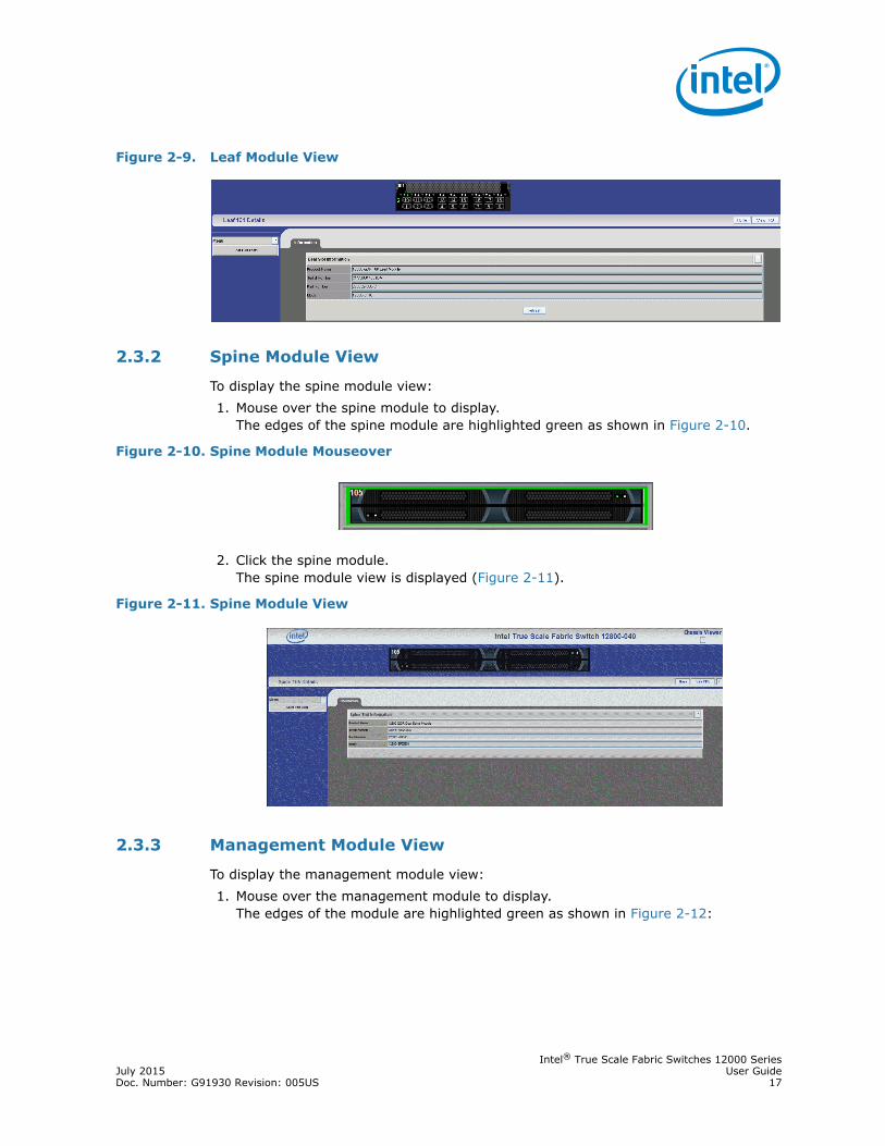
2.3.2 Spine Module View
To display the spine module view:1. Mouse over the spine module to display.
The edges of the spine module are highlighted green as shown in Figure 2-10.
2. Click the spine module. The spine module view is displayed (Figure 2-11).
2.3.3 Management Module View
To display the management module view:1. Mouse over the management module to display.
The edges of the module are highlighted green as shown in Figure 2-12:
Figure 2-9. Leaf Module View
Figure 2-10. Spine Module Mouseover
Figure 2-11. Spine Module View

Intel® True Scale Fabric Switches 12000 SeriesUser Guide July 201518 Doc. Number: G91930 Revision: 005US
2. Click the management module. The management module view is displayed (Figure 2-13).
2.4 Component Details AreaThe Component Details Area (Figure 2-14) for the chassis, spine, leaf, and management module has three areas.
• Details Header• Information area• Menu
2.4.1 Details Header
The Details Header (Figure 2-15) allows the user to execute command tasks for each hardware component. The figure below displays the 12300 Details Header as an example.
Figure 2-12. Management Module Mouseover
Figure 2-13. Management Module View
Figure 2-14. Component Details Area
Intel® True Scale Fabric Switches 12000 SeriesJuly 2015 User GuideDoc. Number: G91930 Revision: 005US 19
All component Details Headers contain the following buttons:• Logout
Note: The Logout button is only displayed if the user has set the User Authentication parameter to Login Enabled through the HTTP Session Configuration submenu. Refer to Section 3.3.3, “HTTP/CLI Session Configuration” on page 33 for more information.
• Reboot• View Field Replaceable Unit (FRU) Information• View Log• Home (12800 series)• Help (12800 series)
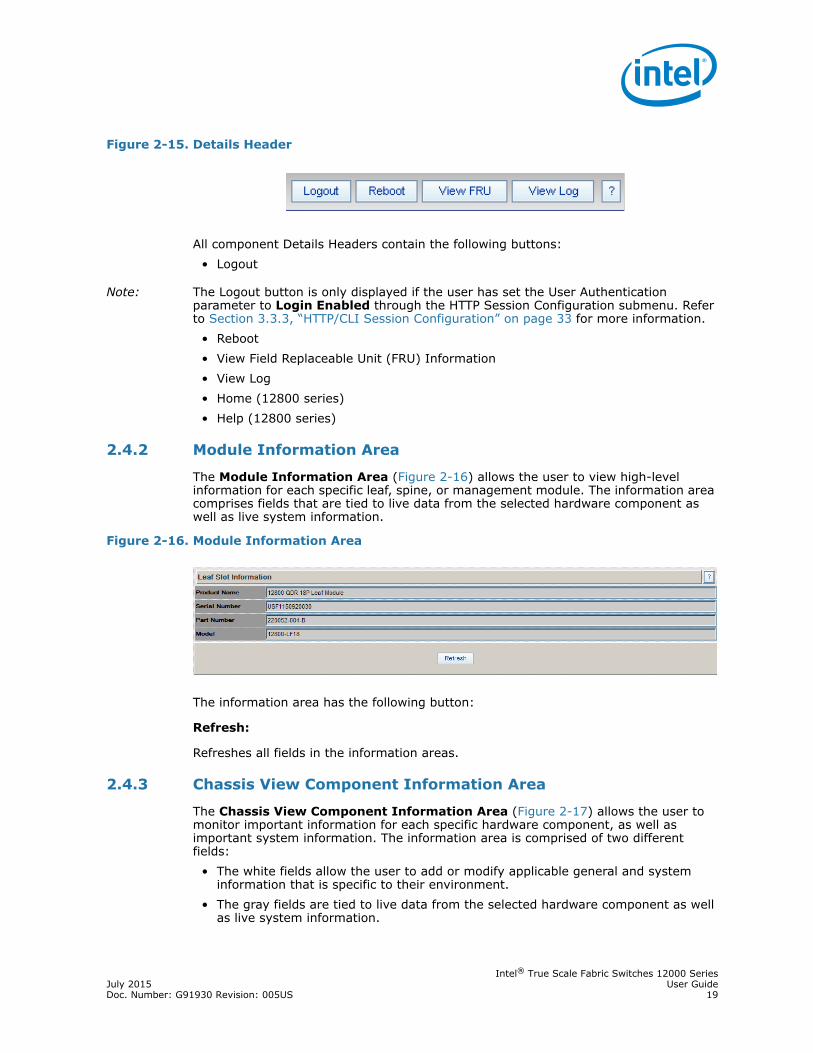
2.4.2 Module Information Area
The Module Information Area (Figure 2-16) allows the user to view high-level information for each specific leaf, spine, or management module. The information area comprises fields that are tied to live data from the selected hardware component as well as live system information.
The information area has the following button:
Refresh:
Refreshes all fields in the information areas.
2.4.3 Chassis View Component Information Area
The Chassis View Component Information Area (Figure 2-17) allows the user to monitor important information for each specific hardware component, as well as important system information. The information area is comprised of two different fields:
• The white fields allow the user to add or modify applicable general and system information that is specific to their environment.
• The gray fields are tied to live data from the selected hardware component as well as live system information.
Figure 2-15. Details Header
Figure 2-16. Module Information Area
Intel® True Scale Fabric Switches 12000 SeriesUser Guide July 201520 Doc. Number: G91930 Revision: 005US
2.4.4 Modifying Switch Component Information
Use the following procedure to modify the fields for switch components:1. Select the applicable tab: LED and Sensors, System, Chassis FRU, Power, Fan,
or Backplane.2. Click on the row to be modified.3. In the text boxes, enter information that is applicable to the existing network
environment.4. To save, click the Apply button at the bottom of the window.
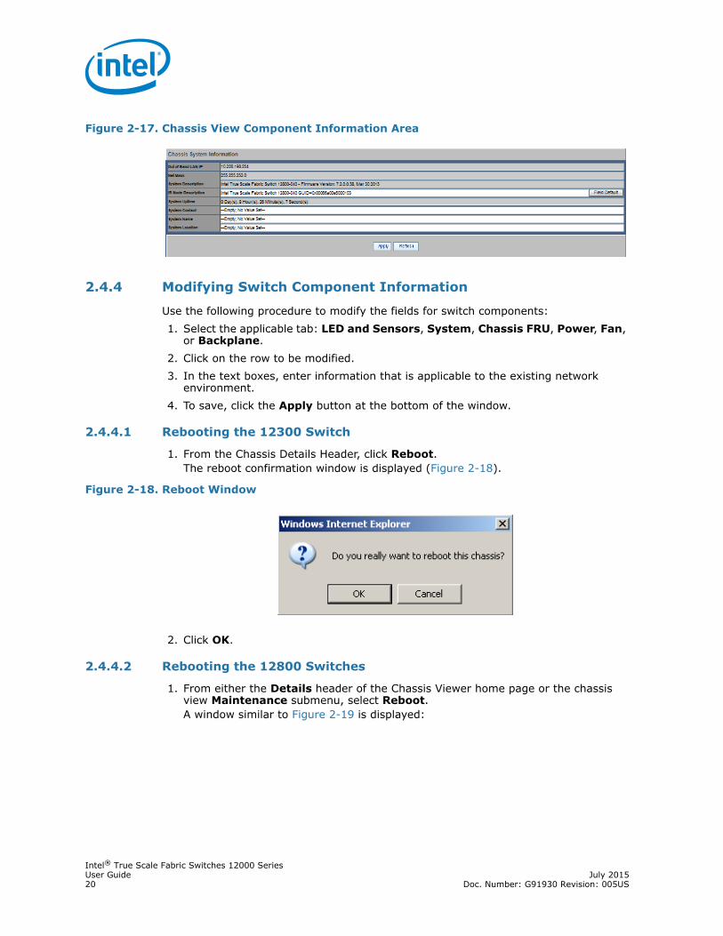
2.4.4.1 Rebooting the 12300 Switch
1. From the Chassis Details Header, click Reboot. The reboot confirmation window is displayed (Figure 2-18).
2. Click OK.
2.4.4.2 Rebooting the 12800 Switches
1. From either the Details header of the Chassis Viewer home page or the chassis view Maintenance submenu, select Reboot. A window similar to Figure 2-19 is displayed:
Figure 2-17. Chassis View Component Information Area
Figure 2-18. Reboot Window

Intel® True Scale Fabric Switches 12000 SeriesJuly 2015 User GuideDoc. Number: G91930 Revision: 005US 21
2. Select the radio button of the management module(s) to be rebooted, or select the Reboot Entire Chassis radio button to reboot the switch and all management modules.
3. Click Reboot.
2.4.5 Chassis View Component Information Area Tabs
The tabs along the top of the information area present information about the following components:
• LED and sensor information• Overall system information• Switch Field Replaceable Unit (FRU) Information• Power supply information• Fan information• Switch backplane information
2.4.5.1 LEDs and Sensors Tab
The LEDs and Sensors tab (Figure 2-20) displays the following information:• Switch component LED information for chassis status, fan, and power supplies.• Slot-based temperature and AC-power sensor data for the internal switching
complex.
Figure 2-19. Reboot Window

Intel® True Scale Fabric Switches 12000 SeriesUser Guide July 201522 Doc. Number: G91930 Revision: 005US
Note: For a detailed explanation of physical LEDs on the hardware components, please refer to the Intel® True Scale Fabric Switches 12000 Series Hardware Installation Guide.
2.4.5.2 System, Chassis FRU, Power, Fan, and Backplane Tabs
Table 2-1 is a list of the System, Chassis FRU, Power, Fan, and Backplane tabs in the Chassis View Component Information Area (Figure 2-20).
Figure 2-20. Chassis View Component Information Area, Showing LEDs and Sensors Tab
Table 2-1. System, Chassis FRU, Power, Fan, and Backplane Tabs
Tab/Information Description
System Tab The System tab displays overall system information for the applicable switch chassis. This information includes the following items:
Out of Band LAN IP The IP address of the switch. The IP address of the switch can be changed by the administrator.
Net Mask The current net mask settings for the Chassis. The net mask of the chassis can be changed by the administrator.
System Description A read-only textual description of the system.
IB Node Description
Assigned by the administrator, the IB node description is an IB fabric-applicable name that will be displayed within the Intel® Fabric Viewer. To reset this field to the default setting, click the Field Default button. Note: If the IB Node Description field has been changed since the last reboot of either management module, the next reboot will be treated as disruptive.
System Uptime The elapsed time since the master management module was re-initialized.
System Contact The textual identification of the contact person and their contact information for this system, assigned by the administrator.
System Name The name for the system, assigned by an administrator. One convention is to use the system's fully qualified domain name.
System Location The location of the system, assigned by an administrator.
Apply Button Saves any changes made by the user in the System tab to memory.

Intel® True Scale Fabric Switches 12000 SeriesJuly 2015 User GuideDoc. Number: G91930 Revision: 005US 23
§ §
Refresh Button Refreshes all fields in the System tab.
Chassis FRU Tab The Chassis FRU tab displays switch Field Replaceable Unit (FRU) information. This information includes the following items:
Type The type of component.
Description A description of the component, assigned by an administrator.
Alias Name Name of the component, assigned by an administrator.
Serial Num Component serial number
DetailA button for each row that displays additional detail about the component. Additional details include: Part Number, Model, Version, Manufacturer Name, Product Name, Manufacturer Identification, and Manufactured Date (if available).
Apply Button Saves any changes made by the user in the Chassis FRU tab to memory.
Refresh Button Refreshes all fields in the Chassis FRU tab.
Power Tab The Power tab displays switch power supply information. This information includes the following items:
Description A description of the component, assigned by an administrator.
Status Displays the status of the component.
Part Num Displays the part number of the component.
DetailA button for each row that displays additional detail about the component. Additional details include: Description, Status, Part Number, Manufacturing Name, Product Name and Manufacturing ID.
Apply Button Saves any changes made by the user in the Power tab to memory.
Refresh Button Refreshes all fields in the Power tab.
Fan Tab The Fan tab displays switch fan information. For descriptions of the fields, see the Power Tab.
Backplane Tab
The Backplane tab displays switch backplane information. The Backplane details button includes the following additional information:• Description• Serial Number• Part Number• Model• Version• Manufacturing Name• Product Name• Manufacturing ID• Manufacturing Date
Additionally, the user can modify the Description field, adding information specific to their network environment.
Table 2-1. System, Chassis FRU, Power, Fan, and Backplane Tabs
Tab/Information Description

Intel® True Scale Fabric Switches 12000 SeriesUser Guide July 201524 Doc. Number: G91930 Revision: 005US

Intel® True Scale Fabric Switches 12000 SeriesJuly 2015 User GuideDoc. Number: G91930 Revision: 005US 25
3.0 Configuration and Monitoring
This section provides detailed, task-oriented descriptions for configuring and monitoring the 12000 switches and their feature functionality.
3.1 Chassis View MenuThe Chassis View Menu (Figure 3-1) allows the user to:
• Set and reset levels for log message files (Refer to “Logging” on page 26)• Perform maintenance (Refer to “Maintenance” on page 31)• View and modify SNMP trap configuration information (Refer to “SNMP” on
page 35)• Perform various administrative tasks related to configuration (Refer to
“Configuration File Administration” on page 41)• Set default trap scenarios related to the switch (Refer to “Chassis Traps” on
page 47)• Obtain IB port information (Refer to “Port Statistics” on page 50)• Set the system time (Refer to “Time Service” on page 59)• Set the OOB LAN IP (Refer to “OOB LAN IP Submenu” on page 62)• Configure the Subnet Manager (Refer to “Fabric Manager Configuration” on
page 65)
Figure 3-1. Chassis View Menu

Intel® True Scale Fabric Switches 12000 SeriesUser Guide July 201526 Doc. Number: G91930 Revision: 005US
3.2 LoggingThe Logging submenu (Figure 3-2) allows the user to set and reset levels for log message files.
3.2.1 Set Level
To efficiently set up Log filtering, enable only those levels that need to appear in the log. The levels are handled by two layers.
The first layer is the Preset Layer. This layer allows the user to select the levels of messages the switch will generate. If the level is selected here, it could be logged into Ram Device or the Syslog Device. Any unselected levels will not be logged to any Device.
The second layer is the Device Levels. This allows the user to select the levels of log messages to be saved.
Note: To save log message levels, select the log level in the Device tab and Preset tab.
The Set Level button allows the user to set log level configuration parameters for all software modules.
To set log levels:1. From the menu, select Logging.
The Set Level button is displayed (Figure 3-3).
2. Click Set Level. 3. The Log System Configurator (Device Tab) window is displayed (Figure 3-4).
Figure 3-2. Logging Submenu
Figure 3-3. Set Level Button

Intel® True Scale Fabric Switches 12000 SeriesJuly 2015 User GuideDoc. Number: G91930 Revision: 005US 27
3.2.1.1 Device Tab
The Device tab (Figure 3-5) presents current log level configuration settings for the following software modules:
• RAM – The circular log buffer contained in memory. To access the contents of this buffer, use the Chassis Viewer View Log button.
• Syslog – Messages that are sent to the syslog host specified on the Syslog tab.
From this window, the user can change any of the log level settings for a specific software module by clicking on the Configure button, which displays a configuration window:
To change any Log Level settings:1. Click the On-Off check box to the right of the setting.2. Click the Apply button to save any changes.
The following list describes each of the Log Level configuration parameters.
Figure 3-4. Log System Configurator: Device Tab
Figure 3-5. Device Tab: Software Module Configurator
Intel® True Scale Fabric Switches 12000 SeriesUser Guide July 201528 Doc. Number: G91930 Revision: 005US
• DUMP – Indicates that a problem has caused the system to produce a system dump file. In most circumstances, it is recommended that the user retrieve the dump that was produced. Support engineers may require the information contained in the dump file to diagnose the cause of the problem.
• FATAL – Indicates that a non-recoverable system problem has occurred. The user should reboot the system or component and verify that the subsystem is fully functional to determine whether the fault has been corrected. If the problem persists, the user should contact the supplier.
• ERROR – Indicates that a serious system error has occurred which might be recoverable. If the system exhibits any instability, the user should reboot the system or component. If errors persist, the user should immediately contact the supplier's technical support.
• ALARM – Indicates that a serious problem has occurred which degrades capacity or service. If the error is recoverable, the user should correct the failure. If the alarm/failure persists, the user should reboot the system at a convenient time. If the problem is still not cleared, the user should contact the supplier.
• WARNING – Indicates that a recoverable problem has occurred. The user does not need to take action.
• PARTIAL – When more information is available, Partial causes additional message-related details to be displayed.
• CONFIGURATION – An informational message indicating changes that a user has made to the system configuration. The user does not need to take any action.
• INFO – Informational messages that occur during a system or component boot. The user does not need to take any action.
• PERIODIC – An informational message containing periodic statistics. The user does not need to take action.
• NOTICE – Notice is used for failures that could be a result of “frequent” user actions, such as a server reboot.
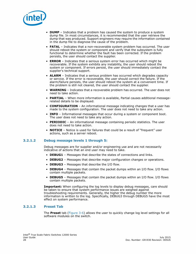
3.2.1.2 Debug message levels 1 through 5:
Debug messages are for supplier and/or engineering use and are not necessarily indicative of actions that an end user may need to take.
• DEBUG1 – Messages that describe the states of connections and links.• DEBUG2 – Messages that describe major configuration changes or operations.• DEBUG3 – Messages that describe the I/O flow. • DEBUG4 – Messages that contain the packet dumps within an I/O flow. I/O flows
contain multiple packets. • DEBUG5 – Messages that contain the packet dumps within an I/O flow. I/O flows
contain multiple packets.
Important: When configuring the log levels to display debug messages, care should be taken to ensure that system performance issues are weighed against troubleshooting requirements. Generally, the higher the debug number the more information is written to the log. Specifically, DEBUG3 through DEBUG5 have the most effect on system performance.
3.2.1.3 Preset Tab
The Preset tab (Figure 3-6) allows the user to quickly change log level settings for all software modules on the switch.

Intel® True Scale Fabric Switches 12000 SeriesJuly 2015 User GuideDoc. Number: G91930 Revision: 005US 29
To change the log level settings:1. Click the On-Off check box to the right of the setting(s). 2. Click the Apply button to save any changes.
3.2.1.4 Syslog Host Tab
The Syslog Host tab (Figure 3-7) allows the user to configure logging messages to be sent to a syslog host through an IP address or domain name server (DNS) host name.
Note: In order to avoid losing log information in the event of a hardware failure, users should configure a syslog server. The switch only saves the in-memory log when it is able to gracefully shutdown, and restore the log from the persistent state when it boots. Power cycling the switch, removing/resetting the management card or any hardware failure that causes an ASYNC reboot will not persistently save the in-memory log.
Note: If the Host IP address is 0.0.0.0, no syslog host is configured, otherwise log messages are sent to the syslog server at a specified IP address and port.
Figure 3-6. Log System Configurator: Preset Tab

Intel® True Scale Fabric Switches 12000 SeriesUser Guide July 201530 Doc. Number: G91930 Revision: 005US
To set up the syslog host:1. In the Hostname or IP text box, enter either the host name or IP address of the
syslog host where the log files are to be saved.2. Click the Apply button to save the IP address.
3.2.1.5 Configure Syslog on the Syslog Server
1. Edit the /etc/sysconfig/syslog file and ensure that the -r is included in the SYSLOGD_OPTIONS. This allows logging from a remote system. For example:
SYSLOGD_OPTIONS="-r -m 0" 2. Type /etc/init.d/syslog restart, and press Enter.
Note: To centralize logging for all switches in an IB fabric, the user can configure each switch to point to the same syslog server, which has the syslog daemon (syslogd) running.
3.2.2 Reset Log Levels
The Reset Levels button resets the logging levels to their factory default values.
To reset the logging levels:1. From the menu, select Logging.
The Reset Levels button is displayed (Figure 3-8).
2. Click Reset Levels. The Reset Levels window is displayed (Figure 3-9).
Figure 3-7. Log System Configurator: Syslog Host Tab
Figure 3-8. Reset Levels Button

Intel® True Scale Fabric Switches 12000 SeriesJuly 2015 User GuideDoc. Number: G91930 Revision: 005US 31
3. To reset the logging levels, click OK.
3.3 MaintenanceThe Maintenance menu (Figure 3-10) allows the user to select an alternate firmware file for the switch, reboot the switch, set and configure authentications for the switch, and set HTTP and CLI session time out parameters, as well as set security requirements for the switch.
Note: For rebooting information, see Section 2.4.4.2, “Rebooting the 12800 Switches” on page 20.
3.3.1 Firmware Update
The Firmware Update button allows the user to select an alternate firmware file for the switch. These alternate files are reflected in the drop-down lists in the Firmware Update window.
To download firmware:1. From the menu, select Maintenance.
The Firmware Update button is displayed (Figure 3-11).
Figure 3-9. Reset Log Levels Window
Figure 3-10. Maintenance Menu
Intel® True Scale Fabric Switches 12000 SeriesUser Guide July 201532 Doc. Number: G91930 Revision: 005US
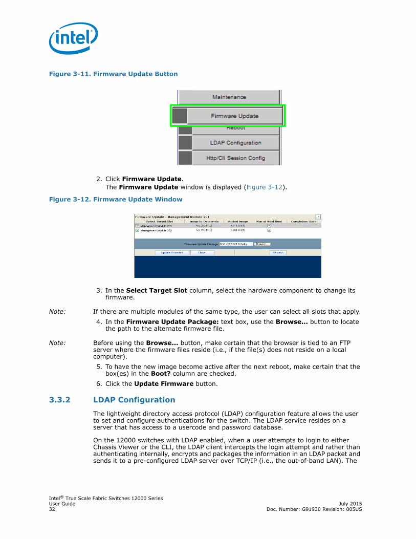
2. Click Firmware Update. The Firmware Update window is displayed (Figure 3-12).
3. In the Select Target Slot column, select the hardware component to change its firmware.
Note: If there are multiple modules of the same type, the user can select all slots that apply.4. In the Firmware Update Package: text box, use the Browse... button to locate
the path to the alternate firmware file.
Note: Before using the Browse... button, make certain that the browser is tied to an FTP server where the firmware files reside (i.e., if the file(s) does not reside on a local computer).5. To have the new image become active after the next reboot, make certain that the
box(es) in the Boot? column are checked.6. Click the Update Firmware button.
3.3.2 LDAP Configuration
The lightweight directory access protocol (LDAP) configuration feature allows the user to set and configure authentications for the switch. The LDAP service resides on a server that has access to a usercode and password database.
On the 12000 switches with LDAP enabled, when a user attempts to login to either Chassis Viewer or the CLI, the LDAP client intercepts the login attempt and rather than authenticating internally, encrypts and packages the information in an LDAP packet and sends it to a pre-configured LDAP server over TCP/IP (i.e., the out-of-band LAN). The
Figure 3-11. Firmware Update Button
Figure 3-12. Firmware Update Window

Intel® True Scale Fabric Switches 12000 SeriesJuly 2015 User GuideDoc. Number: G91930 Revision: 005US 33
LDAP server receives the request, passes it on to the authentication services, and responds to the client with a yes or no, either allowing or denying the user access to the box.
When LDAP is disabled internal authentication becomes the default.
To set up LDAP authentication:1. From the menu, select Maintenance.
The LDAP Configuration button is displayed (Figure 3-13).
2. Click LDAP Configuration. The LDAP Authentication window is displayed (Figure 3-14).
3. In the LDAP Server IP Address box, enter the address of the applicable LDAP server.
4. In the LDAP Server Port box, enter the applicable server port number (the default is 389).
5. Click Apply.
3.3.3 HTTP/CLI Session Configuration
The hyper text transfer protocol (HTTP) and command line interface (CLI) session configuration feature allows the user to set HTTP and CLI session time out parameters, as well as set security requirements for the switch.
The session time out duration is the length of time that a session remains active if there is no GUI activity. If a session is inactive for a time exceeding the time out duration, the user will be logged out.
Figure 3-13. LDAP Configuration Button
Figure 3-14. LDAP Authentication Window

Intel® True Scale Fabric Switches 12000 SeriesUser Guide July 201534 Doc. Number: G91930 Revision: 005US
To modify the HTTP and CLI configurations:1. From the menu, select Maintenance.
The HTTP/CLI Session Config button is displayed (Figure 3-15).
2. Click HTTP/CLI Session Config. The HTTP/CLI Session Configuration window is displayed (Figure 3-16).
3. To modify the session time out duration (in seconds), click on the existing configuration. The row changes to orange.
4. In the HTTP Timeout Duration field, enter the new timeout duration (in seconds). The default is 0 seconds (i.e., no timeout).
5. In the CLI Timeout Duration field, enter the new timeout duration (in seconds). The default is 600 seconds.
6. To change the User Authentication parameter, click on the User Authentication list (Figure 3-17).
7. Select the preferred user authentication method.• Login Enabled - UserName and Password must be entered, and must match what
is in the database of the local switch.
Figure 3-15. HTTP/CLI Session Config Button
Figure 3-16. HTTP/CLI Session Configuration Window
Figure 3-17. User Authentication Dropdown List

Intel® True Scale Fabric Switches 12000 SeriesJuly 2015 User GuideDoc. Number: G91930 Revision: 005US 35
• User Only Required - According to the local switch database, a valid username must be entered. A password is not required.
• Login Disabled - Does not require username or password.• LDAP - Use an LDAP server. If the user name/password validation fails to complete
successfully, check the database of the local switch.8. To change the HTTP Mode parameter, click on the HTTP Mode list (Figure 3-18).
9. Select Enabled or Disabled.10. To change the HTTPs Mode parameter, click on the HTTPs Mode list
(Figure 3-19).
11. Select Enabled or Disabled.12. Click Apply.
3.4 SNMPThe SNMP submenu (Figure 3-20) allows the user to view and modify SNMP trap configuration information.
Note: The following Chassis SNMP MIBs are provided:• icsChassisMib• icsChassisTrapMib• icsConfigFileTrapMib• icsIBStatMib• icsKeyMgmtMib• icsLogConfigMIB• icsMasterMib• icsSmMib
Figure 3-18. HTTP Mode Dropdown List
Figure 3-19. HTTPs Mode Dropdown List
Intel® True Scale Fabric Switches 12000 SeriesUser Guide July 201536 Doc. Number: G91930 Revision: 005US
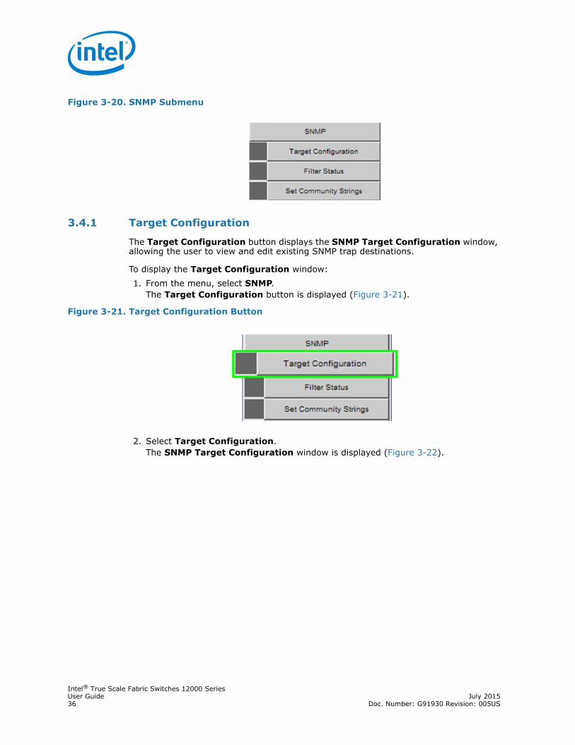
3.4.1 Target Configuration
The Target Configuration button displays the SNMP Target Configuration window, allowing the user to view and edit existing SNMP trap destinations.
To display the Target Configuration window:1. From the menu, select SNMP.
The Target Configuration button is displayed (Figure 3-21).
2. Select Target Configuration.The SNMP Target Configuration window is displayed (Figure 3-22).
Figure 3-20. SNMP Submenu
Figure 3-21. Target Configuration Button

Intel® True Scale Fabric Switches 12000 SeriesJuly 2015 User GuideDoc. Number: G91930 Revision: 005US 37
The top section of the window, SNMP Target Addresses, allows the user to determine what type of SNMP traps are sent, and where they are sent. The rows provide an area for specifying multiple trap destinations. The middle section, SNMP Address Form, allows the user to record new SNMP address information for the applicable module. The bottom section of the window, SNMP Target Parameters, allows the user to configure each trap destination with version, optional security information, and filtering mechanisms.
The Apply button applies the current settings to either the SNMP Target Addresses or SNMP Target Parameters section. The Add button saves changes made to the SNMP Address Form section.
Note: The Target Configuration window is used for viewing and modifying existing SNMP target entries. It is not used for creating new target entries.
To create a new target entry, use the following CLI command:
snmpTargetAddr add -n name -a addr [-p port] [-t timeout] [-r retry_count] [-l tag_list] [-v parameters] [-s storage_type]For example, to add a trap target with the IP address 192.168.0.123 that accepts SNMP v2c style traps:
snmpTargetAddr add -n traphost1 -a 192.168.0.123 -v "v2 params"
Or, to add the same target except using SNMP v1 traps:
snmpTargetAddr add -n traphost1 -a 192.168.0.123 -v "v1 params"
3.4.1.1 Target Configuration Window Field Descriptions
The following are descriptions for each field in the Target Configuration window:
Figure 3-22. SNMP Target Configuration Window

Intel® True Scale Fabric Switches 12000 SeriesUser Guide July 201538 Doc. Number: G91930 Revision: 005US
SNMP Target Addresses:• Address Name
Specifies a unique, administrator-defined name the system uses to identify a row. • Transport Domain
Specifies the transport type of the address contained in the snmpTargetAddrTAddress object (e.g., 1.3.6.1.6.1.1 = udp, 1.3.6.1.4.1.1977.200.1 = tcp).
• Transport AddressSpecifies the IP address in dotted decimal format.
Note: The combination of the Transport Domain and the Transport Address determines the trap destination.• Port
Specifies the TCP or UDP port where the SNMP trap is sent.• Timeout
Specifies the time (in milliseconds) that the trap sender waits on a response before re-sending the trap.
• Retry CountSpecifies the number of attempts to be made to send the trap after a timeout condition occurs.
Note: Timeout and Retry Count are SNMP v2.c and above (not applicable for v1 traps).• Tag List
Specifies which traps should be sent to this particular destination.
Note: RFC2233 specifies the link up/down traps. Including RFC2233 in the Tag List specifies that the trap receiver will get link up/down traps.• Parameters
Specifies a mapping to an entry in the SNMP Target Parameters table, determining the version of SNMP to use.
• Storage TypeThis field determines whether or not the entry is saved for each reboot of the switch.— Nonvolatile means that the value is saved, and remains after each subsequent
reboot. — Volatile or Other indicates it will not be saved.
• StatusIndicates the current status of the row. The row may be in one of three states:— Active— Not in service— Not Ready
Note: A status of not in service indicates that the current row will not be used in the event a trap is generated by the system. Toggling a trap to not in service, which temporarily suspends trap forwarding, may be useful to keep values intact.
SNMP Target Parameters:
Note: Changes can only be made to rows that have a status of not in service.• Parameter Name

Intel® True Scale Fabric Switches 12000 SeriesJuly 2015 User GuideDoc. Number: G91930 Revision: 005US 39
Specifies a mapping to an entry in the SNMP Target Parameters table, determining the version of SNMP to use.
• MP ModelThe Message Processing Model to be used when generating SNMP messages for entry. Values for this field are 0 for SNMP v1, 1 for SNMP v2 and 3 for SNMP v3.
• Security ModelThe Security Model to be used when generating SNMP messages using this entry. Values for this field are 1 for SNMP v1, 2 for SNMP v2, or 3 for SNMP v3.
• Security NameSecurity name identifies the entity for whom SNMP messages will be generated.
Note: This is equivalent to the community string in an SNMP get.• Security Level
One of three options:— NoAuthNoPriv: No Authentication, no privacy.— AuthNoPriv: Authentication, no privacy.— AuthPriv: Authentication and privacy
• Storage TypeThis field determines whether or not the entry is saved for each reboot of the switch.— Nonvolatile means that the value is saved, and remains after each subsequent
reboot. — Volatile or Other indicates it will not be saved.
• StatusIndicates the current status of the row. The row may be in one of three states:— Active— Not in service— Not Ready
Note: A status of not in service indicates that the current row will not be used in the event a trap is generated by the system. Toggling a trap to not in service, which temporarily suspends trap forwarding, may be useful to keep values intact.
3.4.2 Filter Status
The SNMP Filter Status window allows the user to view parameters for rfc2273 (SNMP-NOTIFICATION-MIB).
To view SNMP filter status:1. From the menu, select SNMP
The Filter Status button is displayed (Figure 3-23).

Intel® True Scale Fabric Switches 12000 SeriesUser Guide July 201540 Doc. Number: G91930 Revision: 005US
2. Click Filter Status. The SNMP Filter Status window is displayed (Figure 3-24).
3.4.3 Set Community Strings
The Set Community Strings window allows the user to set two SNMP community names:
• Read Only Community Name• Read/Write Community Name
To set the Community Strings:1. From the menu, select SNMP.
The Set Community Strings button is displayed (Figure 3-25).
Figure 3-23. Filter Status Button
Figure 3-24. SNMP Filter Status Window

Intel® True Scale Fabric Switches 12000 SeriesJuly 2015 User GuideDoc. Number: G91930 Revision: 005US 41
2. Click Set Community Strings. The Set Community Strings window is displayed (Figure 3-26).
The first field, Read Only Comm. Name is the community string that when specified in an SNMP client, allows read-only access to SNMP fields exported by the SNMP server. The second field, Read/Write Comm. Name is the community string that when specified in an SNMP client, allows read and write access to SNMP fields exported by the SNMP server.
3. In each text box, enter a meaningful name (such as public and private displayed in Figure 3-26), and click on Apply.
3.5 Configuration File AdministrationThe Config File Admin menu (Figure 3-27) allows the user to perform various administrative tasks related to the configuration files for each module populating the switch.
Figure 3-25. Set Community Strings Button
Figure 3-26. Set Community Strings Window
Figure 3-27. Configuration File Administration Menu

Intel® True Scale Fabric Switches 12000 SeriesUser Guide July 201542 Doc. Number: G91930 Revision: 005US
3.5.1 Administer
The Administer window allows the user to set backup and restore scenarios for the configuration file of applicable switch modules.1. From the Chassis View menu (Figure 3-1), select Config File Admin.
The Administer button is displayed (Figure 3-28).
2. Click Administer. The Configuration File Administration window is displayed (Figure 3-29).
3. Click on the module to be modified. 4. The row changes to orange.5. In the Mode column, click the drop-down and select the configuration file
administration mode for a module (Figure 3-30).
Figure 3-28. Configuration File Administration - Administer
Figure 3-29. Configuration File Administration Window

Intel® True Scale Fabric Switches 12000 SeriesJuly 2015 User GuideDoc. Number: G91930 Revision: 005US 43
The following is a description of each mode option:• Disabled
Following an Auto Restore of a configuration file to a module, the system sets the module mode to Disabled. This allows the user to verify that the configuration file is correct, before returning the module to Auto Backup mode. In the Disabled mode, use the Backup and Restore buttons to either back up or restore a configuration file.
• Auto BackupAll configuration changes to a module are automatically backed up.
• Auto RestoreThe most recent configuration file is restored to a module inserted into a specific Chassis slot. This is useful as a prerequisite to hot swapping a module.
6. To save, click Apply.
Note: The Clear button deletes the configuration file from the switch.
3.5.2 Host Upload/Download
The Host Up/Download windows allows the user to:• Upload configuration files from a server.• Download saved configuration files from the switch to a server.1. From the Chassis View menu (Figure 3-1), select Config File Admin.
The Host Up/Down button is displayed (Figure 3-31).
Figure 3-30. Configuration File Administration - Mode Drop-down
Figure 3-31. Configuration File Administration - Host Up/Down

Intel® True Scale Fabric Switches 12000 SeriesUser Guide July 201544 Doc. Number: G91930 Revision: 005US
2. Click Host Up/Down. The Configuration File Upload/Download window is displayed (Figure 3-32).
To upload a configuration file from a server to the switch:1. For a selected module, click the Upload button.
The Upload window is displayed (Figure 3-33).
2. Type the path to the desired server location, or click Browse to locate the correct path.
3. Click Submit.
To download a configuration file from the switch to a server:1. For a selected module, click the Download button. The File Download window is
displayed.2. Click Save.3. In the Save As window, locate the correct path to the desired server location, and
click Save.
3.5.3 Trap Control
The Trap Control window allows the user to set default trap scenarios related to configuration files.1. From the Chassis View menu (Figure 3-1), select Config File Admin.
The Trap Control button is displayed (Figure 3-34).
Figure 3-32. Configuration File Upload/Download Window
Figure 3-33. Upload Window

Intel® True Scale Fabric Switches 12000 SeriesJuly 2015 User GuideDoc. Number: G91930 Revision: 005US 45
2. Click Trap Control. The Trap Control window is displayed (Figure 3-35).
3. Select or deselect the desired trap(s).
Note: To generate an immediate trap, click the applicable Gen Trap button.4. To save settings, click on Apply.
Note: If the trap is not selected, the Gen Trap button will not generate a trap.
The following are definitions for each configuration file trap:• CfgSrvBackupFailed
The server was instructed to back up a file for a particular slot, which failed.• CfgSrvSyncError
Synchronization to the slave Management Module failed. The problem should be resolved and attempted manually.
• CfgSrvGenErrorA general error has occurred.
• CfgSrvFileRestoredThe configuration files have been restored to a particular slot.
• CfgSrvFileBackedupThe configuration files have been successfully backed up for a particular slot.
• CfgSrvModeDisabled
Figure 3-34. Trap Control
Figure 3-35. Configuration File Trap Control Window

Intel® True Scale Fabric Switches 12000 SeriesUser Guide July 201546 Doc. Number: G91930 Revision: 005US
An event has occurred that has caused the slot mode to be set to disabled. The user should resolve the error and reset the mode to the proper value for the affected slot.
Note: The default settings for this window are as shown above. The user should not change the defaults unless instructed by Technical Support.
3.5.4 Subnet Manager Configuration File
The Subnet Manager Configuration File window allows the user to upload and download new Intel® Fabric Manager embedded subnet manager files, as well as start and restart all applicable master and standby subnet managers using the new file.1. From the Chassis View menu (Figure 3-1), select Config File Admin.
The Subnet Manager Config File button is displayed (Figure 3-36).
2. Click Subnet Manager Config File. The Subnet Manager Configuration window is displayed (Figure 3-37).
3. To download the current configuration file, right-click on the file name in the Current config file text box, then choose either Save Target As or Save Link As (depending upon which browser is being used) as displayed in Figure 3-38.
Figure 3-36. Subnet Manager Configuration File
Figure 3-37. Subnet Manager Configuration File Window

Intel® True Scale Fabric Switches 12000 SeriesJuly 2015 User GuideDoc. Number: G91930 Revision: 005US 47
4. To upload a configuration file, in the Upload Config File text box: enter the path to the alternate embedded subnet manager file (intel_fm.xml). If the path is not known, the user can use the Browse... button to locate it.
5. Once the new file is located, click the Upload button.6. In the Subnet Manager Control window for the master subnet manager, click
Stop, Refresh, then Restart to have the new file become active.7. If applicable in the Subnet Manager Control window for the slave subnet
manager, click Refresh to have the new file become active.
3.6 Chassis TrapsThe Chassis Trap Control window allows the user to set default trap scenarios related to the switch.1. From the Chassis View menu (Figure 3-1), select Chassis Traps.
The Trap Control button is displayed (Figure 3-39).
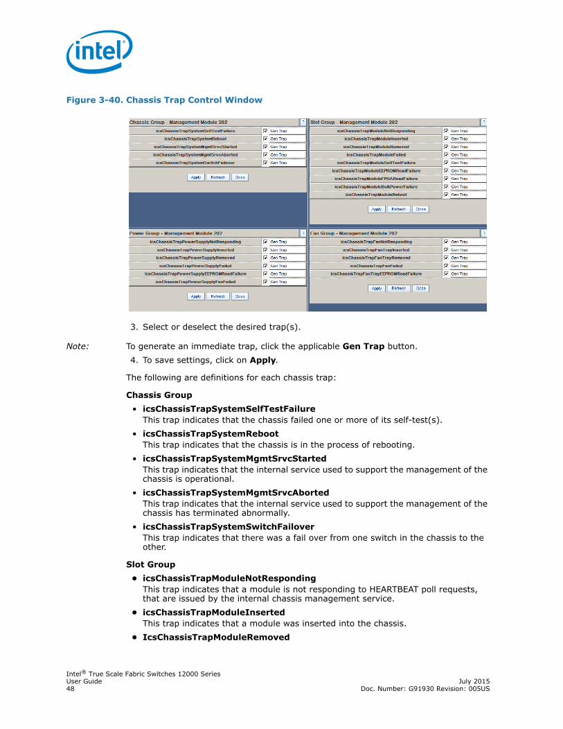
2. Click Trap Control. The Chassis Trap Control window is displayed (Figure 3-40).
Figure 3-38. Subnet Manager Configuration File Save As
Figure 3-39. Chassis Trap Control
Intel® True Scale Fabric Switches 12000 SeriesUser Guide July 201548 Doc. Number: G91930 Revision: 005US
3. Select or deselect the desired trap(s).
Note: To generate an immediate trap, click the applicable Gen Trap button.4. To save settings, click on Apply.
The following are definitions for each chassis trap:
Chassis Group• icsChassisTrapSystemSelfTestFailure
This trap indicates that the chassis failed one or more of its self-test(s).• icsChassisTrapSystemReboot
This trap indicates that the chassis is in the process of rebooting.• icsChassisTrapSystemMgmtSrvcStarted
This trap indicates that the internal service used to support the management of the chassis is operational.
• icsChassisTrapSystemMgmtSrvcAborted This trap indicates that the internal service used to support the management of the chassis has terminated abnormally.
• icsChassisTrapSystemSwitchFailover This trap indicates that there was a fail over from one switch in the chassis to the other.
Slot Group• icsChassisTrapModuleNotResponding
This trap indicates that a module is not responding to HEARTBEAT poll requests, that are issued by the internal chassis management service.
• icsChassisTrapModuleInsertedThis trap indicates that a module was inserted into the chassis.
• IcsChassisTrapModuleRemoved
Figure 3-40. Chassis Trap Control Window
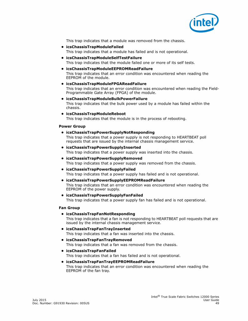
Intel® True Scale Fabric Switches 12000 SeriesJuly 2015 User GuideDoc. Number: G91930 Revision: 005US 49
This trap indicates that a module was removed from the chassis.• icsChassisTrapModuleFailed
This trap indicates that a module has failed and is not operational.• icsChassisTrapModuleSelfTestFailure
This trap indicates that the module failed one or more of its self tests.• icsChassisTrapModuleEEPROMReadFailure
This trap indicates that an error condition was encountered when reading the EEPROM of the module.
• icsChassisTrapModuleFPGAReadFailureThis trap indicates that an error condition was encountered when reading the Field-Programmable Gate Array (FPGA) of the module.
• icsChassisTrapModuleBulkPowerFailureThis trap indicates that the bulk power used by a module has failed within the chassis.
• icsChassisTrapModuleRebootThis trap indicates that the module is in the process of rebooting.
Power Group• icsChassisTrapPowerSupplyNotResponding
This trap indicates that a power supply is not responding to HEARTBEAT poll requests that are issued by the internal chassis management service.
• icsChassisTrapPowerSupplyInsertedThis trap indicates that a power supply was inserted into the chassis.
• icsChassisTrapPowerSupplyRemovedThis trap indicates that a power supply was removed from the chassis.
• icsChassisTrapPowerSupplyFailedThis trap indicates that a power supply has failed and is not operational.
• icsChassisTrapPowerSupplyEEPROMReadFailureThis trap indicates that an error condition was encountered when reading the EEPROM of the power supply.
• icsChassisTrapPowerSupplyFanFailedThis trap indicates that a power supply fan has failed and is not operational.
Fan Group• icsChassisTrapFanNotResponding
This trap indicates that a fan is not responding to HEARTBEAT poll requests that are issued by the internal chassis management service.
• icsChassisTrapFanTrayInsertedThis trap indicates that a fan was inserted into the chassis.
• icsChassisTrapFanTrayRemovedThis trap indicates that a fan was removed from the chassis.
• icsChassisTrapFanFailedThis trap indicates that a fan has failed and is not operational.
• icsChassisTrapFanTrayEEPROMReadFailureThis trap indicates that an error condition was encountered when reading the EEPROM of the fan tray.

Intel® True Scale Fabric Switches 12000 SeriesUser Guide July 201550 Doc. Number: G91930 Revision: 005US
3.7 Port StatisticsThe Chassis View Port Statistics provides IB port information for all of the external and internal ports of the switch.
To view port statistical information, do the following:1. From the Chassis View menu (Figure 3-1), click Port Stats.
The IB Port Stats button is displayed (Figure 3-41).
2. Click IB Port Stats. The IB Port Statistics window is displayed (Figure 3-42).
3.7.1 Understanding Port Naming Conventions
The following is an explanation of the conventions used in the Port Name column.Leaf modules/ports:
L = Leaf module numberP = Leaf module port numberExample: L101P01 is leaf module 101 port number 1.
Interswitch Link (ISL) Ports:S = Spine module number
Figure 3-41. IB Port Statistics
Figure 3-42. Chassis IB Port Statistics

Intel® True Scale Fabric Switches 12000 SeriesJuly 2015 User GuideDoc. Number: G91930 Revision: 005US 51
L = Leaf module numberA = Spine module switch chip AB = Spine module switch chip BExample: S113AP13L225P24 is the ISL between spine module 113, switch chip A, port 13 and leaf module 225, port 24.
Note: Spine chips are referenced by the spine number and the switch chip identifier. Each spine module contains two switch chips (Switch chip A and B).
3.7.2 Port Statistics Field Descriptions
Link State:
Indicates whether the IB link associated with the physical port is up or down. Possible values are no state change, down, init, armed, active, and unknown.
Physical State:
Indicates whether the internal connection to the IB port is up or down. Possible values are No State Change, Sleep, Polling, Disabled, Training, Up, and Error Recovery.
Link Down Default:
Indicates the default down state as set by the Fabric Manager. Possible values are No State Change, Sleep, Polling, and Unknown.
Active Link Width:
Indicates the number of full duplex serial links that are currently being used on a port. The current bandwidth capability of a port is determined by multiplying this value by the Active Link Speed of this port. For instance a 4X DDR link has a bandwidth capability of 20Gb/s.
Note: Values of 1X are possible in this field with 4X IB cables if poor cable connections or defective 4X IB cables are used.
Link Width Enabled:
Link Width Enabled is the allowed link width(s) that a port can arbitrate to. Normally, this defaults to the Link Width Supported value, but can be overridden by the subnet manager.
Link Width Supported:
Indicates the link width in terms of multipliers of 2.5 Gbit/sec full duplex serial links supported by the port.
Active Link Speed:
Indicates the speed of the full duplex serial link. This is either 2.5Gbps (single data rate, or SDR), or 5.0Gbps (double data rate, or DDR), or 10.0Gbps (quad data rate, or QDR).
Link Speed Enabled:
Link Speed Enabled is the allowed link speed(s) that a port can arbitrate to. Normally this defaults to the Link Speed Supported value, but can be overridden by the subnet manager.

Intel® True Scale Fabric Switches 12000 SeriesUser Guide July 201552 Doc. Number: G91930 Revision: 005US
Link Speed Supported:
The supported link speed of the port. This could be 2.5Gbps (SDR), 5.0Gbps (DDR), 10Gbps (QDR) or a combination.
3.7.3 IB Statistics Field Descriptions
Transmit 32 Bit Words:
The number of 32-bit data words transmitted by the port, not including flow control and VCRC data.
Receive 32 Bit Words:
The number of 32-bit data words received by the port, not including flow control and VCRC data.
Transmit Packets:
The number of data packets transmitted by the port, not including flow control packets.
Receive Packets:
The number of data packets received by the port, not including flow control packets.
Symbol Errors:
The number of times a 8B10B encoding violation, or a disparity violation was detected. If multiple errors are detected simultaneously (in more than one lane), the counter only increments by one. The value of the counter is not incremented past 65535. The Performance Manager may reset and/or consolidate the results of this counter.
Link Error Recovery:
Indicates the number of times the link error recovery process happened successfully. The value of the counter is not incremented past 65535. The Performance Manager may reset and/or consolidate the results of this counter.
Link Downed:
The number of times the link error recovery process failed. The value of the counter is not incremented past 65535. The Performance Manager may reset and/or consolidate the results of this counter.
Receive Errors:
Number of errors received on the port.
Remote Physical Errors Received:
Indicates bit errors on a link other than the physically attached link.
Transmit Discards:
Number of port transmit discards.
Local Link Integrity Errors:
An error caused by a marginal link. Depending upon the number of code violations, physical switch problems are detected at the physical layer. These errors are based on a count of local physical errors.

Intel® True Scale Fabric Switches 12000 SeriesJuly 2015 User GuideDoc. Number: G91930 Revision: 005US 53
Excessive Buffer Overrun:
This error is detected when the Overrun Errors threshold is exceeded by the number of consecutive flow control update periods with at least one overrun error in each period given in the PortInfo attribute.
Pkey Violations Inbound:
Indicates the number of times an invalid partition key (PKey) was received. PKeys support an advanced IB feature for logically partitioning a physical subnet into logical access domains.
Pkey Violations Outbound:
Indicates the number of times an invalid PKey was sent. PKeys support an advanced IB feature for logically partitioning a physical subnet into logical access domains.
Raw Violations Inbound:
Number of times raw inbound packet discarded.
Raw Violations Outbound:
Number of times raw outbound packet was discarded.
3.7.4 Leaf and Spine Module IB Port Statistics
To access IB port statistics for a specific leaf or spine module, perform the following steps.
3.7.4.1 Leaf Modules
1. Select a leaf module. The leaf module view is displayed.
2. From the Leaf menu, select Leaf Port Stats. The IB Port Stats button is displayed (Figure 3-43).
3. Click IB Port Stats. The IB Port Statistics - Leaf window is displayed (Figure 3-44).
Figure 3-43. Leaf IB Port Stats Menu

Intel® True Scale Fabric Switches 12000 SeriesUser Guide July 201554 Doc. Number: G91930 Revision: 005US
For information on the each IB port statistic field, refer to the section “Port Statistics Field Descriptions” on page 51.
3.7.4.2 Spine Modules
1. Select a spine module. The spine module view is displayed.
2. From the Spine menu, select Spine Port Stats. The IB Port Stats button is displayed (Figure 3-45).
3. Click IB Port Stats. The IB Port Statistics - Spine window is displayed (Figure 3-46).
Figure 3-44. Leaf Port Statistics Window
Figure 3-45. Spine IB Port Stats Menu

Intel® True Scale Fabric Switches 12000 SeriesJuly 2015 User GuideDoc. Number: G91930 Revision: 005US 55
For information on the each IB port statistic field, refer to the section “Port Statistics Field Descriptions” on page 51.
3.7.5 Set Field Thresholds
The Set Field Thresholds window allows the user to set, for a specific parameter(s), an error message threshold for the cable ports on the switch.
To change error reporting thresholds, do the following:1. Click on Port Stats.
The Set Field Thresholds button is displayed (Figure 3-47).
2. Click on Set Field Thresholds. The Set Field Thresholds window is displayed (Figure 3-48).
Figure 3-46. Spine Port Statistics Window
Figure 3-47. Set Field Thresholds
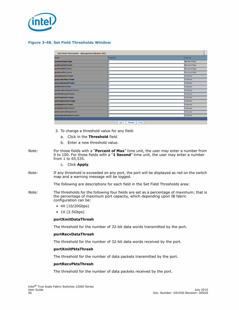
Intel® True Scale Fabric Switches 12000 SeriesUser Guide July 201556 Doc. Number: G91930 Revision: 005US
3. To change a threshold value for any field: a. Click in the Threshold field.b. Enter a new threshold value.
Note: For those fields with a “Percent of Max” time unit, the user may enter a number from 0 to 100. For those fields with a “1 Second” time unit, the user may enter a number from 1 to 65,535.
c. Click Apply.
Note: If any threshold is exceeded on any port, the port will be displayed as red on the switch map and a warning message will be logged.
The following are descriptions for each field in the Set Field Thresholds area:
Note: The thresholds for the following four fields are set as a percentage of maximum; that is the percentage of maximum port capacity, which depending upon IB fabric configuration can be:
• 4X (10/20Gbps)• 1X (2.5Gbps)
portXmitDataThresh
The threshold for the number of 32-bit data words transmitted by the port.
portRecvDataThresh
The threshold for the number of 32-bit data words received by the port.
portXmitPktsThresh
The threshold for the number of data packets transmitted by the port.
portRecvPktsThresh
The threshold for the number of data packets received by the port.
Figure 3-48. Set Field Thresholds Window

Intel® True Scale Fabric Switches 12000 SeriesJuly 2015 User GuideDoc. Number: G91930 Revision: 005US 57
Note: The thresholds for the following fields are set based upon the number of error messages which can occur in one second. The value can be from 1 to 65,535.
portSymbolErrThresh
The threshold for the number of times a 8B10B encoding violation, or a disparity violation was detected on the port.
portLinkErrRecvThresh
The threshold for the number of times the link error recovery process happened successfully on the port.
portLinkDownedThresh
The threshold for the number of times the link error recovery process failed on the port.
portRecvErrThresh
The threshold for the number of errors received on the port.
portRecvRemPhysErrThresh
The threshold for the number of remote physical errors received on the port.
portXmitDiscardThresh
The threshold for the number of transmit discards received on the port.
portPKeyViolInThresh
The threshold for the number of times PKey inbound was invalid on the port.
portPKeyViolOutThresh
The threshold for the number of times PKey outbound was invalid on the port.
portRawViolInThresh
The threshold for the number of times a raw inbound packet was discarded by the port.
portRawViolOutThresh
The threshold for the number of times a raw outbound packet was discarded by the port.
portLocalLinkIntegThresh
The threshold for the number of local link integrity errors on the port.
portExcBufferOverrunThresh
The threshold for the number of excessive buffer overrun errors on the port.
3.7.6 Port Beacon
The Port Beacon feature allows the user to enable IB port(s) LEDs to flash, assisting a user in locating a port.
Note: The Port Beacon feature can also be accessed via the Leaf Module menu.

Intel® True Scale Fabric Switches 12000 SeriesUser Guide July 201558 Doc. Number: G91930 Revision: 005US
1. From the Chassis menu, click Port Stats.The Port Beacon button is displayed (Figure 3-49).
2. Click Port Beacon. The Port Beacon window is displayed (Figure 3-50).
3. For the desired leaf or 12300 IB port, select the Beacon Enabled check box. 4. Click Apply.
The physical port will blink. In Chassis Viewer, the IB Link Status LED for the port is outlined as shown in Figure 3-51.
Figure 3-49. Port Beacon
Figure 3-50. Port Beacon Window
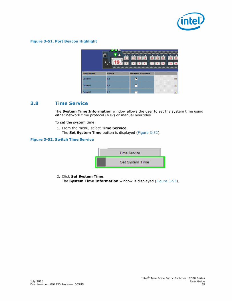
Intel® True Scale Fabric Switches 12000 SeriesJuly 2015 User GuideDoc. Number: G91930 Revision: 005US 59
3.8 Time ServiceThe System Time Information window allows the user to set the system time using either network time protocol (NTP) or manual overrides.
To set the system time:1. From the menu, select Time Service.
The Set System Time button is displayed (Figure 3-52).
2. Click Set System Time. The System Time Information window is displayed (Figure 3-53).
Figure 3-51. Port Beacon Highlight
Figure 3-52. Switch Time Service

Intel® True Scale Fabric Switches 12000 SeriesUser Guide July 201560 Doc. Number: G91930 Revision: 005US
Note: If using Network Time Protocol (NTP) and host names (instead of IP addresses), DNS information must first be set up using the CLI command dnsParamsSet. Remember to reboot the switch after executing this command.
Note: For detailed information, refer to the Intel® True Scale Fabric Switches 12000 Series CLI Reference Guide.
To use NTP:1. Click the Use Network Time Protocol? check box (Figure 3-54).
Figure 3-53. System Time Information Window
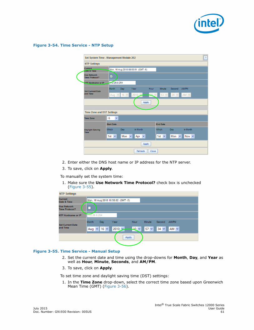
Intel® True Scale Fabric Switches 12000 SeriesJuly 2015 User GuideDoc. Number: G91930 Revision: 005US 61
2. Enter either the DNS host name or IP address for the NTP server.3. To save, click on Apply.
To manually set the system time:1. Make sure the Use Network Time Protocol? check box is unchecked
(Figure 3-55).
Figure 3-55. Time Service - Manual Setup2. Set the current date and time using the drop-downs for Month, Day, and Year as
well as Hour, Minute, Seconds, and AM/PM.3. To save, click on Apply.
To set time zone and daylight saving time (DST) settings:1. In the Time Zone drop-down, select the correct time zone based upon Greenwich
Mean Time (GMT) (Figure 3-56).
Figure 3-54. Time Service - NTP Setup

Intel® True Scale Fabric Switches 12000 SeriesUser Guide July 201562 Doc. Number: G91930 Revision: 005US
2. Using the Which, Day, and in Month drop-downs, set the start and end dates for daylight saving time.
3. To save, click on Apply.
Time Zone Tips:
In the U.S. the following time zones are in effect:• Eastern Standard Time = GMT –5• Central Standard Time = GMT –6• Mountain Standard Time = GMT –7• Pacific Standard Time = GMT -8
Daylight Saving Time Tips:
For most of the United States, Daylight Saving Time (DST) begins at 2 a.m. on the second Sunday of March, and ends at 2 a.m. on the first Sunday in November.
Additionally, for those regions in the United States that do not observe DST, the start and end dates in the Which, Day, and in Month settings should be set to the exact same date.
3.9 OOB LAN IP Submenu
3.9.1 Configuring the Switch OOB IP Address
To configure the Switch IP address:1. From the menu, select OOB LAN IP
The Set OOB LAN IP button is displayed (Figure 3-57).
Figure 3-56. Time Service - Time Zone/Daylight Saving Time Setup
Figure 3-57. Set Switch OOB IP Address Button
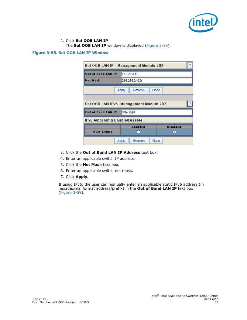
Intel® True Scale Fabric Switches 12000 SeriesJuly 2015 User GuideDoc. Number: G91930 Revision: 005US 63
2. Click Set OOB LAN IP.The Set OOB LAN IP window is displayed (Figure 3-58).
3. Click the Out of Band LAN IP Address text box.4. Enter an applicable switch IP address.5. Click the Net Mask text box.6. Enter an applicable switch net mask.7. Click Apply.
If using IPv6, the user can manually enter an applicable static IPv6 address (in hexadecimal format address/prefix) in the Out of Band LAN IP text box (Figure 3-59).
Figure 3-58. Set OOB LAN IP Window

Intel® True Scale Fabric Switches 12000 SeriesUser Guide July 201564 Doc. Number: G91930 Revision: 005US
8. To automatically configure and assign addresses from an IPv6 router, click the Auto Config Enabled radio button.
Note: The IPv6 router must be configured to assign addresses using stateless address auto configuration.9. Click Apply.
3.9.2 Configuring the Switch Default Gateway IP Address
The Set Default Gateway IP window allows the user to configure the IP address for the default gateway to route packets from the OOB management port to an external network.
To configure the Switch default gateway IP address:1. From the menu, select OOB LAN IP.
The Set Default Gateway IP button is displayed (Figure 3-60).
2. Click Set Default Gateway IP.The Set Default Gateway IP window is displayed (Figure 3-61).
Figure 3-59. Set OOB LAN IPv6 Window
Figure 3-60. Set Switch Default Gateway IP Address Button

Intel® True Scale Fabric Switches 12000 SeriesJuly 2015 User GuideDoc. Number: G91930 Revision: 005US 65
3. Click the Gateway address text box.4. Type in the correct switch default gateway IP address.5. Click Apply.
Note: If the DHCP option is selected, no gateway address is necessary.
3.10 Fabric Manager Configuration
Note: This section assumes the user has purchased and activated the embedded version of the Fabric Manager.
3.10.1 Automatically starting the Fabric Manager
To enable the Fabric Manager to automatically start at boot time:1. From the menu, select Subnet Manager.
The Configuration button is displayed (Figure 3-62).
2. Click Configuration. The Subnet Manager Configuration window is displayed (Figure 3-63).
3. To configure the Fabric Manager to automatically start with each boot, click Enabled.
Note: If the user wants to manually activate the Fabric Manager, click Disabled.
Figure 3-61. Set Default Gateway IP Window
Figure 3-62. Subnet Manager Submenu
Figure 3-63. Subnet Manager Configuration Window

Intel® True Scale Fabric Switches 12000 SeriesUser Guide July 201566 Doc. Number: G91930 Revision: 005US
4. For switches in a redundant management configuration, the Start On Slave option should be set to Disabled. In the event that the Fabric Manager on the master Management Module is disabled, the Fabric Manager on the slave Management Module will turn on automatically when it becomes the chassis management module.
5. Click Apply.
3.11 Management Module MenuThe Management Module Menu contains selections for logging, maintenance, subnet manager, and license keys (Figure 3-64).
3.11.1 Logging
The Logging submenu allows the user to view and purge the log message file.
3.11.2 Viewing the Log
Each management module maintains a separate log. The View Log button allows the user to view the message log.
To view the message log:1. From the menu, select Logging.
The View Log button is displayed (Figure 3-65).
2. Click View Log. The Log Message window is displayed (Figure 3-66).
Figure 3-64. Management Module Menu
Figure 3-65. View Log Button

Intel® True Scale Fabric Switches 12000 SeriesJuly 2015 User GuideDoc. Number: G91930 Revision: 005US 67
To save a log message for further analysis, perform the following steps:1. From the Log Messages window, select Edit, Select All (or CTRL + A).2. Select Edit, Copy (or CTRL + C).3. Open a text editing package, such as Notepad.4. Select Edit, Paste (or CTRL + V).5. Save as a plain text (.txt) file.
3.11.3 Purging the Log
The Purge Log button purges the RAM, clearing the log file(s).
To purge the log:1. From the menu, click Logging.
The Purge Log button is displayed (Figure 3-67).
2. Click Purge Log. 3. The Purge Log confirmation window is displayed (Figure 3-68).
Figure 3-66. Sample Message Log
Figure 3-67. Purge Log Button

Intel® True Scale Fabric Switches 12000 SeriesUser Guide July 201568 Doc. Number: G91930 Revision: 005US
4. Click OK. 5. The message log file is now purged.
3.11.4 Select Boot Image
The Select Boot Image button allows the user to choose an alternative boot image for the switch. To select a boot image:1. From the menu, select Maintenance.
The Select Boot Image button is displayed (Figure 3-69).
2. Click Select Boot Image. The Boot Image Selection window is displayed (Figure 3-70).
By mousing over either radio button in the Boot Image Selection window, the user can glean additional information about each file, as shown in Figure 3-71.
Figure 3-68. Purge Log Confirmation Window
Figure 3-69. Select Boot Image Button
Figure 3-70. Boot Image Selection Window

Intel® True Scale Fabric Switches 12000 SeriesJuly 2015 User GuideDoc. Number: G91930 Revision: 005US 69
To choose a new boot image:1. Click on a radio button of the new boot image.2. Click Apply.
This is the image that will run after the next reboot.
3.11.5 Post Diagnostics
The Post Diagnostic feature allows the user to choose tests for various switch components that can be run in real time. These are tests that are not run during the power-on phase.1. From the menu, select Maintenance.
The Post Diagnostics button is displayed (Figure 3-72).
2. Click Post Diagnostics.3. The Post Diagnostics window is displayed (Figure 3-73).
Figure 3-71. Boot Image File Pop Up
Figure 3-72. Post Diagnostics Button

Intel® True Scale Fabric Switches 12000 SeriesUser Guide July 201570 Doc. Number: G91930 Revision: 005US
4. Select the test(s) to be run and click Run Tests. The test results are displayed in the Test Result column (Figure 3-74). Additional information is posted to the Result-Ext column:
3.12 Fabric Manager ControlThis section assumes the user has purchased and activated the embedded version of the Fabric Manager.
3.12.1 Accessing the Subnet Manager Control Window
The Subnet Manager Control window presents status information relating to the Fabric Manager and provides a mechanism for starting, restarting, and stopping the Fabric Manager.1. From the Management Module menu, click Subnet Manager.
The Control button is displayed (Figure 3-75).
2. Click Control. The Subnet Manager Control window is displayed (Figure 3-76).
Figure 3-73. Post Diagnostics Window
Figure 3-74. Post Diagnostics Results Output
Figure 3-75. Subnet Manager Control Button
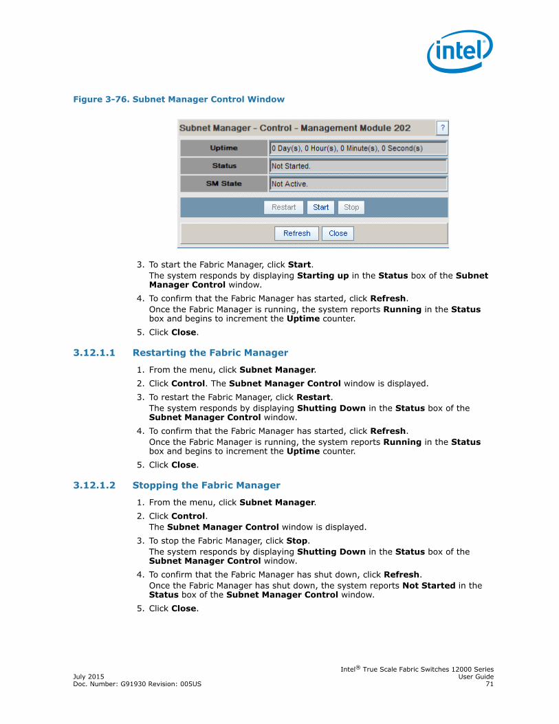
Intel® True Scale Fabric Switches 12000 SeriesJuly 2015 User GuideDoc. Number: G91930 Revision: 005US 71
3. To start the Fabric Manager, click Start. The system responds by displaying Starting up in the Status box of the Subnet Manager Control window.
4. To confirm that the Fabric Manager has started, click Refresh. Once the Fabric Manager is running, the system reports Running in the Status box and begins to increment the Uptime counter.
5. Click Close.
3.12.1.1 Restarting the Fabric Manager
1. From the menu, click Subnet Manager.2. Click Control. The Subnet Manager Control window is displayed.3. To restart the Fabric Manager, click Restart.
The system responds by displaying Shutting Down in the Status box of the Subnet Manager Control window.
4. To confirm that the Fabric Manager has started, click Refresh. Once the Fabric Manager is running, the system reports Running in the Status box and begins to increment the Uptime counter.
5. Click Close.
3.12.1.2 Stopping the Fabric Manager
1. From the menu, click Subnet Manager.2. Click Control.
The Subnet Manager Control window is displayed.3. To stop the Fabric Manager, click Stop.
The system responds by displaying Shutting Down in the Status box of the Subnet Manager Control window.
4. To confirm that the Fabric Manager has shut down, click Refresh. Once the Fabric Manager has shut down, the system reports Not Started in the Status box of the Subnet Manager Control window.
5. Click Close.
Figure 3-76. Subnet Manager Control Window
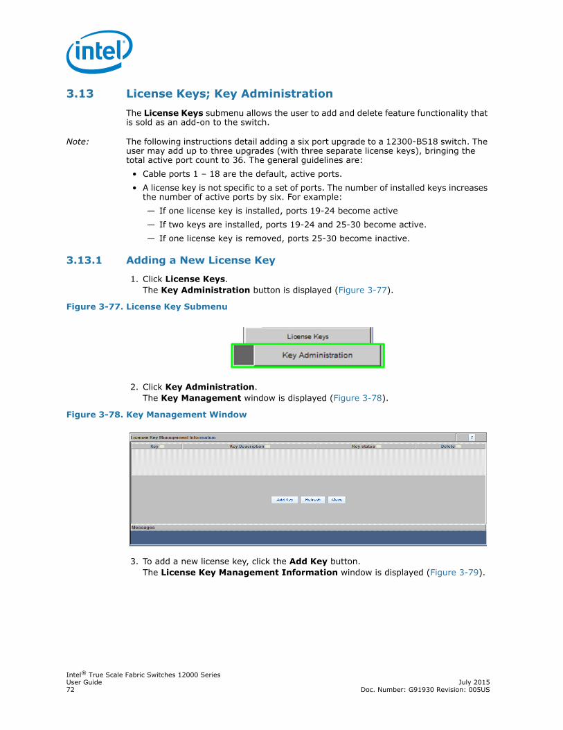
Intel® True Scale Fabric Switches 12000 SeriesUser Guide July 201572 Doc. Number: G91930 Revision: 005US
3.13 License Keys; Key AdministrationThe License Keys submenu allows the user to add and delete feature functionality that is sold as an add-on to the switch.
Note: The following instructions detail adding a six port upgrade to a 12300-BS18 switch. The user may add up to three upgrades (with three separate license keys), bringing the total active port count to 36. The general guidelines are:
• Cable ports 1 – 18 are the default, active ports.• A license key is not specific to a set of ports. The number of installed keys increases
the number of active ports by six. For example:— If one license key is installed, ports 19-24 become active— If two keys are installed, ports 19-24 and 25-30 become active.— If one license key is removed, ports 25-30 become inactive.
3.13.1 Adding a New License Key
1. Click License Keys. The Key Administration button is displayed (Figure 3-77).
2. Click Key Administration. The Key Management window is displayed (Figure 3-78).
3. To add a new license key, click the Add Key button. The License Key Management Information window is displayed (Figure 3-79).
Figure 3-77. License Key Submenu
Figure 3-78. Key Management Window

Intel® True Scale Fabric Switches 12000 SeriesJuly 2015 User GuideDoc. Number: G91930 Revision: 005US 73
4. Enter the license key information in the New Key text box, and click Apply.
3.13.2 Deleting a License Key
1. Click on the License Keys submenu.2. Click on Key Administration.
The Key Management window is displayed (Figure 3-80).
3. To delete a license key, click the Delete button. The system prompts with Are you sure you want to clear key: ()? dialog box (Figure 3-81).
4. Click OK to delete.
§ §
Figure 3-79. License Key Management Information Window
Figure 3-80. Key Management Delete
Figure 3-81. License Key Delete Prompt