intelligent antenna solutions for umts: algorithms and...
TRANSCRIPT
IEEE Communications Magazine • October 20042 0163-6804/04/$20.00 © 2004 IEEE
ADAPTIVE ANTENNAS ANDMIMO SYSTEMS FOR WIRELESS SYSTEMS
INTRODUCTION
The use of multi-antenna arrays in wireless com-munications coupled with “intelligent” process-ing algorithms of their signals has recently beendubbed intelligent antennas (IAs). IAs continueto be a hot topic of research and development inan effort to boost the performance of wirelesscommunications and provide competitive advan-tage to equipment vendors and operators. In thisarticle we focus on Universal Mobile Telecom-munications System (UMTS) frequency-divisionduplex (FDD) standards (R99, R4, and R5).Before addressing UMTS-specific issues, theconcept of beamforming is explained next.
As shown in Fig. 1 the mobile, in most envi-ronments, may be modeled as embedded in acluster of local scatterers (cluster 0) [1]; forexample, the body of the user, the ground, ornearby cars. When the base station antennas areelevated, the base station may be modeled asbeing far away from scatterers. The signal origi-nating from the mobile station or user equip-ment (UE) transmitter is reflected by clusters inthe far field of the base station antennas (clus-ters 1 and 2). Associated with each reflection isa time delayed and phase shifted version of thetransmit signal that arrives at the mobile via adifferent direction of arrival (DoA). The loca-tions of scatterers are assumed to be identicalbetween uplink and downlink. This symmetry isfundamental to the operation of IA in FDD sys-tems.
When multiple antenna elements at the basestation are closely spaced, the received signalsfrom a particular mobile are correlated at thebase station antennas. Thus, the base station canestimate long-term statistics — more specifically,second order moments such as the correlationmatrix of the channel. These estimates can beused to calculate weights that satisfy an optimali-ty criterion (e.g., minimizing the uncoded symbolerror rate seen by the mobile. When theseweights multiply the transmitted signal, the sig-nals arrive co-phased at the terminal location,
Pantelis Monogioudis, Keith Conner, Deepak Das, Sridhar Gollamudi, Jung Ah C. Lee, Aris L. Moustakas,
Shirish Nagaraj, Anil M. Rao, Robert A. Soni, and Yifei Yuan, Lucent Technologies
ABSTRACT
This article outlines the development of intel-ligent antenna (IA) solutions for UMTS, a third-generation W-CDMA system. Since the selectionof an antenna configuration paired with realiz-able uplink/downlink algorithms that can satisfyall operating environments is a broad task, thisarticle focus is on cost-effective antenna arraysfor macrocells. Algorithms that exploit theantenna configurations and act at both the physi-cal and MAC layers are highlighted and support-ed by simulation results. Two solutions stand outfor UMTS: a universal beamforming algorithmthat unifies user-specific and fixed beamformingunder one framework, and multibeam schedul-ing (MBS) that significantly increases downlinkpacket data throughput using the concept ofcode reuse in conjunction with beamforming.The article summarizes the critical issues thatwere faced in the development of an IA solutioncapable of delivering the theoretically promisedbenefits to end users.
Intelligent Antenna Solutions for UMTS:Algorithms and Simulation Results
� Table 1. An explanation of base station antenna configurations.
Antenna configuration Fig. Description
1V (a) 1 column with vertical polarization (V-pol)
ULA-2V (b) 2 closely spaced V-pol columns
ULA-4V (c) 4 V-pol columns
DIV-1X (d) 1 column with dual-slant polarization (X-pol)
CLA-2X (e) 2 closely spaced X-pol columns
CLA-3X (f) 1 X-pol middle column with two closelyspaced columns of +45-pol
BM-4X (g) 4 X-pol columns with dual Butler matrix
DIV-2X (h) 2 widely spaced X-pol columns

IEEE Communications Magazine • October 2004 3
resulting in immediate signal-to- interferenceratio (SIR) benefits. The SIR benefits translateto reduced power consumption at the base sta-tion for power-controlled channels. For sharedchannels, the SIR benefits result in improvedthroughput and delay metrics.
Figure 2 shows the antenna configurations abase station constrained by 12 radio frequency(RF) cables. Twelve RF cables can support 4antennas per sector for a 3-sector base stationand 2 antennas per sector for a 6-sector base sta-tion. Each configuration is explained in Table 1.
Only IA solutions that can be implemented incost-effective baseband processing are consid-ered in this article. “Applique” analog solutionssuch as BM-4X are not considered. Since DIV-2X is most suitable in the downlink for BLASTand BLAST is not being considered for inclusionin UMTS until after Release 5, BLAST is notconsidered in this article. For mobile terminals,antenna configurations are related to terminaltypes.
Voice terminals are assumed to have one ortwo antennas, and high-speed packet-data-ori-ented terminals — such as those serving theUMTS high-speed downlink packet access(HSDPA) markets — are assumed to have morethan two antennas (as allowed by the form factorand the cost of materials budget).
STANDARDS SUPPORT OFINTELLIGENT ANTENNAS
The third-generation wideband code-divisionmultiple acces (W-CDMA) standard drafted inthe Third Generation Partnership Project(3GPP) has been designed to allow multipleantenna configurations in both the base stationand the mobile. The specifications support IAvia two primary means. First, pilot channels aredefined to provide reference signals that canhelp the estimation and detection functions ofthe receiver. Second, protocols are defined tohandle measurements necessary for allocatingpilot channels, configuring radio links, and trans-ferring measurements so that radio resourceswithin the access network can be allocated opti-mally.
In the uplink, all 3G systems employ a dedi-cated pilot that is multiplexed with the datachannel. Although the uplink pilot can be dis-continued for short periods of time, the long-term second order statistics estimated at the
base station are relatively unaffected. The uplinkpilot adds coherent gain and significantlyimproves not only the estimation of spatial cor-relation across the antenna array but also theestimation of multipath delay.
In the downlink, three pilot channels havebeen defined:• Primary common pilot channel (P-CPICH)• Secondary common pilot channel (S-
CPICH)• DPCCH PILOT (DPILOT) (known as dedi-
cated pilot)In many situations, the IA solution is propri-
etary to the base station vendor, and the mobileis, in principle, unaware of beamforming. Fur-thermore, not all physical channels can be beam-formed. For example, users that do not have anestablished dedicated connection cannot bebeamformed.
The P-CPICH allows a terminal (without anestablished dedicated connection) to select thebest sector and decode the broadcast informa-
� Figure 1. The symmetry of the scattering information between uplink anddownlink is a key enabler for beamforming in FDD.
Cluster 1
Cluster 2
Cluster 0
Per-cluster angle-spread
Composite angle-spread
Mean DOA ofeach cluster
� Figure 2. Base station antenna configurations.
(a) (b) (d)(c) (e) (f) (g) (h)
Dual butler matrix

IEEE Communications Magazine • October 20044
tion necessary to establish a connection to thenetwork. The P-CPICH is usually transmittedwith a sector pattern that has a (3 dB)beamwidth of 65˚ or 90˚.1 The P-CPICH servesas a phase reference allowing the CDMA recep-tion functions at the terminal.
The use of P-CPICH for beamformed usersmay seem infeasible at first as the user-specificbeam and sector patterns are quite different,leading to a mismatch between the phases of thetraffic signal and the pilot reference. However,as proposed in this article and earlier in [2],beamforming algorithms can be made adaptiveto widen the mobile directed beam dependingon the composite angle spread of the uplink andminimize this mismatch. The proposed algo-rithms optimize beamforming gain in the pres-ence of pilot-traffic mismatch. UMTS providesthe capability to configure the terminal not touse P-CPICH as a phase reference but to useeither S-CPICH or dedicated PILOT or a com-
bination of both.The DPILOT in UMTS appears to be an
excellent pilot source for beamforming since it istime-multiplexed with the data stream and goesthrough the same channel as the traffic. Howev-er, for achieving quality similar to commonpilots, the DPILOT power must be increased.Thus, as the number of users increase, the totalincrease in power consumption makes the use ofthe DPILOT inefficient.
Figure 3 shows an example of four orthogo-nal S-CPICHs resulting from a ULA-4V antennaconfiguration using an antenna beamwidth of90˚. Each of the four beams is supported by anS-CPICH that can be allocated as a phase refer-ence. The allocation of S-CPICH per user ismade on the basis of uplink measurements per-formed at the BS. Higher-layer signaling isinvolved when the S-CPICH phase referenceneeds to change due to movement of the termi-nal.
SIMULATION METHODOLOGYRealistic simulation modelsthat capture not onlythe performance of the physical layer but alsothe performance of the MAC and radio resourcecontrol layers are necessary for developing IAalgorithms and determining antenna configura-tions that optimize system capacity. The Wire-less Algorithm Validation Environment(WAVE) is an internal Lucent simulation tool,developed to support performance studies for avariety of radio interfaces. Key components ofthe adopted simulation methodology are theconcept of a virtual decoder and the elaboratespatial channel model described next.
THE VIRTUAL DECODERFigure 4 depicts a multitiered cloverleaf cell lay-out simulation snapshot. Within this environ-ment the air interface abstractions of both thelink and system levels are accessible, denoted co-simulation. Co-simulation provides verificationof the system-level abstraction using the link-level capabilities and vice versa. A link-level useris simulated at an oversampled chip rate. At thesystem level, multiple users are simulated at arate of 1 sample/time slot.2 At this rate theinstantaneous SIR (at the reference point shownin Fig. 5) is calculated, assuming a block-fadingmodel over a time slot. The reference point ofthe measurement is at the input to the virtualdecoder (VD), after despreading, channel com-pensation, and spatiotemporal combining orequalization.
A VD uses a metric extracted from the vectorof SIR measurements and implements the map-ping from this metric to a block error decision(cyclic redundancy check, CRC, result). TheCRC decision drives the link adaptation loopssuch as outer-loop power control for dedicatedchannel communications and rate control forhigh-speed packet data over shared channelcommunications. The designed VD metricproves to be very accurate for both convolution-al and turbo coded transport channels. A singleuser simulated at either 1 sample/slot or 1 sam-ple/chip exhibits identical statistical perfor-mance. This instantaneous value interface (IVI)
� Figure 3. Fixed beam pattern for ULA-4V. Solidlines are the fixed beams, and the dotted line isthe per-column antenna pattern.
Antenna pattern file name = Kathrien 741989 M45 OTAntenna pattern = Kathrein Cross-PolBeam width = 90°Frequency = 2140 MHzPeak gain = 14.85 dBd
180 0
90 30
20
10
90
30
330
300240
210
150
120
270
� Table 2. Power-delay profile (PDP) mixture.
PDP Relative power to first path (dB) Velocity OccurrenceRelative delay (ns) (km/h) prob (%)
Pedestrian A [0.0, –9.7, –19.2] 3.0 30[0.0, 110.0, 190.0 ]
Pedestrian B [0.0, –0.9, –4.9, –8.0, –7.8] 10.0 30[0.0, 200.0, 800.0, 1200.0, 2300.0]
Vehicular A [0.0, –1.0, –9.0, –10.0, –15.0] 30.0 20[0.0, 310.0, 710.0, 1090.0, 1730.0]
Vehicular B [0.0, –2.5, –12.8, – 10.0, –16.0] 120.0 10[0.0, 300.0, 8900.0, 12900.0, 20000.0] &
Single path [0.0] 3.0 10[0.0]
1 For most practical casesit is not transmitted usinga single element butshaped before being trans-mitted by the antennaarray.
2 One time-slot = 0.667µs for UMTS.

IEEE Communications Magazine • October 2004 5
methodology allows flexibility in determiningrealistic capacity achieving criteria. For example,capacity can now be ascertained from system-level quality of service (QoS) statistics ratherthan exclusive use of transmit power outagestatistics or received noise rise.
THE SPATIAL CHANNEL MODELThe channel model is a critical factor in deter-mining the relative performance of IA tech-niques. The extent to which beamforming iseffective is determined by the angular width ofthe incoming energy — the composite root meansquare (RMS) angle spread. As shown in Fig. 1,typically each cluster has a different angle ofarrival (AoA) at the base station. Thus, the AoAof each cluster is modeled as a random variablechosen from a Gaussian distribution with vari-ance equal to the composite angle spread. Eachcluster associated with a path has an inherentRMS angle spread of its own, which is assumedto be fixed at 5˚. Shadow fading follows theGudmunson model [3] — with decorrelationlength of 50 m and inter-BS correlation of 0.5.These assumptions are a simplified set of thoseadopted by the 3GPP standards bodies [1]. Inaddition to the spatial structure of the channel,the temporal behavior of the channel, describedby the delay spread, must be considered. Thisquantity characterizes the temporal width overwhich the incoming energy is distributed. Largedelay spread can be exploited by the receiver toprovide diversity gain. For the purposes of thisarticle, we have used a discrete set of channelpower-delay profiles (PDP) and a set of associat-ed maximum Doppler frequencies. The PDPmixture is shown in Table 2.
THE IA SOLUTION FOR DEDICATEDAND CONNECTIONLESS CHANNELS
This section presents simulated IA performanceresults for power controlled dedicated and com-mon control channels. The most widespread ser-vice carried over dedicated channels for UMTSis adaptive multirate (AMR) coded voice andassociated radio resource control signaling. In allcases, 12.2 kb/s AMR and 3.4 kb/s associated sig-naling were assumed with the latter exhibitingthe same activity factor as the voice traffic — aworst case assumption in terms of power con-sumption. Out of the common control channels,the random access channel (RACH) providesthe primary method for connectionless transportof both signaling as well as low to moderateoffered loads of packet data traffic in the uplink.As such it is not closed-loop power controlledand represents, depending on the cell configura-tion, a significant source of uplink noise rise.
UPLINK DEDICATED CHANNEL BEAMFORMINGIn the uplink, IA signal processing is done on aper path basis. Minimum mean squared error(MMSE) spatial combiners attempt to removethe spatially correlated interference. PracticalMMSE algorithms are limited by the number ofantennas and the Doppler frequency of themobile of interest. This spatial processor iscalled a precombiner as it precedes the final tem-
poral RAKE combining. A block diagram of thisprocessing is shown in Fig. 6.
Practical BSs feature routing of receiveduplink signals to the baseband demodulator,(i.e., multipath searching is being performedover multiple sectors). The antenna interfaceblock represents this routing function that pre-sents to each MMSE precombiner only theantennas that correspond to the same sector.
Two spatial correlation matrices are used tocalculate the precombiner weights. The firstmatrix is the global correlation matrix, referencedat the antenna connectors. This matrix containsthe spatial correlations of the total signal plusinterference in the sector that result fromCDMA transmissions. The second correlationmatrix is user-specific, referenced at the outputof the user despreader. The effects of channelestimation noise are reduced by averaging overrelatively short periods of time. The weight vec-tor for the MMSE precombiner is given by theprincipal eigenvector of the product of theinverse of the global correlation matrix and theuser-specific correlation matrix. The complexityof the weight calculation can be reduced to anacceptable implementation cost. The RAKEcombining process follows the application of theweight vector and combines the signals tempo-rally into the final log-likelihood ratio metricused by the decoder.
The determination of the capacity limits in
� Figure 4. A simulation snapshot showing a dedi-cated channel user-specific beamforming sce-nario (beams shown are directed to the user ofinterest only).
Cell 0 Cell ixx x
x
xx
xx
xxx
xx
x
xxxxx
xx x
xxx x
xxxx
xxx
x
xxxx
xx
xx
x xx
xx
xx
x xxxx
Cell i + 1
UE 0
� Figure 5. The SIR estimation model for Rake receivers.
Reference pointfor instantaneous
SIR estimation
Transmitter Channel Rakereceiver
Virtualdecoder

IEEE Communications Magazine • October 20046
the uplink are based on the following criteria:• Noise rise limit: The noise rise averaged
over one slot does not exceed 7 dB morethan 1 percent of the time [4].
• QoS limit: The fraction of terminals in QoSoutage (defined as the per-user outage [4])is less than 5 percent.The uplink capacity limits for voice are shown
in Fig. 7. The following observations can bemade:• The CLA-2X antenna configuration which
exploits receive diversity performs betterthan ULA-4V. Simulations show that theaverage noise rise of ULA-4V is about 0.3dB higher than that of CLA-2X. Similarly,the fraction of mobiles in QoS outage islower for the CLA-2X configuration.
• The six-sector BS with receive diversity pro-vides a gain of 167 percent over that of athree-sector BS with receive diversity.
RACH CHANNEL BEAMFORMINGEnhancing the RACH preamble detection aswell as message reception is more of a require-
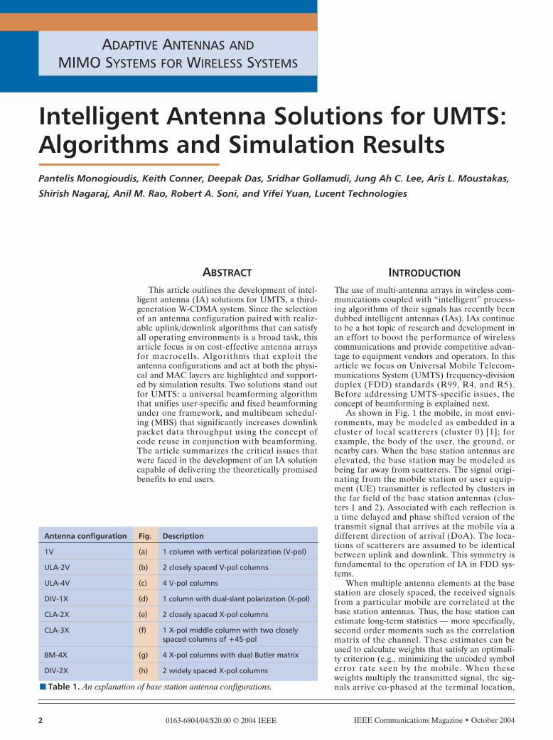
ment than an option for IA-enhanced dedicatedchannels. The RACH preamble carries a patternknown to the receiver, called a signature, and thejob of the detector is to acknowledge successfulreception of the preamble, paving the way forfurther signaling exchange and final admission ofthe user to the network. Detection structuresbased on the generalized likelihood ratio test(GLRT) lead to detectors that work either onthe principle of maximum eigenvalue of thereceived correlation matrix or by selecting thebest beam out of a set of fixed beams. The gener-ic RACH detector structure is shown in Fig. 8.
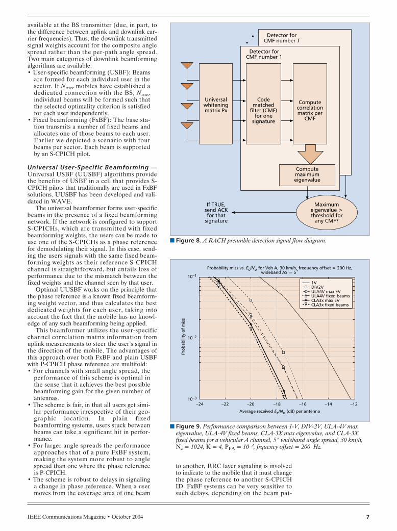
The signal flow diagram resembles the dedi-cated channel signal flow in the pre-whiteningstep, but the despreading part is implementedvia code matched filters (CMFs) rather thanserial correlators. The CMF span covers themaximum delay spread associated with the cellcoverage determined by the link budget. Link-level simulation results that quantify the proba-bility of missed detection are shown in Fig. 9.
The results indicate that searching over afinite set of beams (fixed beam detector) givesreasonably good results in a variety of spatialinterference scenarios. Thus, a fixed beam detec-tor can be a good trade-off against the maximumeigenvalue solution. The penalty of ULA overCLA configurations is less than 2 dB for the sce-nario presented. System-level results not pre-sented in this article also indicate that the mobilestation transmit power for the ULA-4V configu-ration is higher by less than 1 dB than that forthe CLA-3X configuration, notably because theRACH has inherent retransmission diversity.
DOWNLINK DEDICATEDCHANNEL BEAMFORMING
Uplink receiver processing is performed on a perpath basis. This approach is affordable due tothe inherent multipath diversity of spread spec-trum signals and the capability of the receiver toestimate the uplink channel. In the downlink,the knowledge of the downlink channel is not
� Figure 6. An MMSE spatial precombiner signal flow diagram.
Downlinkweight
calculation
Estimateshort-term Ryy
Calculateuplink weightsMaxElg(Rxx Ryy)
Antennaprecombiner
(L fingers)
Rakefinger
combiner Todecoder
To searcher/preambledetector
Long-termaveraging
Estimateshort-term Rxx
Choleskydecomposition
Rxx1/2Rxx
1/2
Antennasource
interfaceDespreaders(L fingers)
Long-termaveraging
� Figure 7. Uplink capacity limits of IA technologies for 12.2 kb/s.
Gain (%)
Uplink capacity gain over DIV1X for AMR 12.2 kb/s,angle spread per path = 5˚
(Ped-A 3 km/h 30%, Ped-B 10 km/h 30%, Veh-A 30 km/h 20%,Veh-B 120 km/h 10%, 1-path K = 10 3 kmph 10%)
180
122
0DIV1X-k65
ULA4V-k65
DIV1X-n33(6-cell)
CLA2X-k65
200160140120100806040200
167
192
IEEE Communications Magazine • October 2004 7
available at the BS transmitter (due, in part, tothe difference between uplink and downlink car-rier frequencies). Thus, the downlink transmittedsignal weights account for the composite anglespread rather than the per-path angle spread.Two main categories of downlink beamformingalgorithms are available:• User-specific beamforming (USBF): Beams
are formed for each individual user in thesector. If Nuser mobiles have established adedicated connection with the BS, Nuserindividual beams will be formed such thatthe selected optimality criterion is satisfiedfor each user independently.
• Fixed beamforming (FxBF): The base sta-tion transmits a number of fixed beams andallocates one of those beams to each user.Earlier we depicted a scenario with fourbeams per sector. Each beam is supportedby an S-CPICH pilot.
Universal User-Specific Beamforming —Universal USBF (UUSBF) algorithms providethe benefits of USBF in a cell that provides S-CPICH pilots that traditionally are used in FxBFsolutions. UUSBF has been developed and vali-dated in WAVE.
The universal beamformer forms user-specificbeams in the presence of a fixed beamformingnetwork. If the network is configured to supportS-CPICHs, which are transmitted with fixedbeamforming weights, the users can be made touse one of the S-CPICHs as a phase referencefor demodulating their signal. In this case, send-ing the users signals with the same fixed beam-forming weights as their reference S-CPICHchannel is straightforward, but entails loss ofperformance due to the mismatch between thefixed weights and the channel seen by that user.
Optimal UUSBF works on the principle thatthe phase reference is a known fixed beamform-ing weight vector, and thus calculates the bestdedicated weights for each user, taking intoaccount the fact that the mobile has no knowl-edge of any such beamforming being applied.
This beamformer utilizes the user-specificchannel correlation matrix information fromuplink measurements to steer the user’s signal inthe direction of the mobile. The advantages ofthis approach over both FxBF and plain USBFwith P-CPICH phase reference are multifold:• For channels with small angle spread, the
performance of this scheme is optimal inthe sense that it achieves the best possiblebeamforming gain for the given number ofantennas.
• The scheme is fair, in that all users get simi-lar performance irrespective of their geo-graphic location. In plain fixedbeamforming systems, users stuck betweenbeams can take a significant hit in perfor-mance.
• For larger angle spreads the performanceapproaches that of a pure FxBF system,making the system more robust to anglespread than one where the phase referenceis P-CPICH.
• The scheme is robust to delays in signalinga change in phase reference. When a usermoves from the coverage area of one beam
to another, RRC layer signaling is involvedto indicate to the mobile that it must changethe phase reference to another S-CPICHID. FxBF systems can be very sensitive tosuch delays, depending on the beam pat-
� Figure 8. A RACH preamble detection signal flow diagram.
Detector forCMF number T
Computecorrelationmatrix per
CMF
Maximumeigenvalue >threshold for
any CMF?
If TRUE,send ACKfor that
signature
Computemaximumeigenvalue
Codematched
filter (CMF)for one
signature
Universalwhiteningmatrix Px
Detector forCMF number 1
� Figure 9. Performance comparison between 1-V, DIV-2V, ULA-4V maxeigenvalue, ULA-4V fixed beams, CLA-3X max eigenvalue, and CLA-3Xfixed beams for a vehicular A channel, 5˚ wideband angle spread, 30 km/h,Nc = 1024, K = 4, PFA = 10–3, frquency offset = 200 Hz.
Average received Ec/No (dB) per antenna
Probability miss vs. Ec/No for Veh A, 30 km/h, frequency offset = 200 Hz,wideband AS = 5˚
–14 –12–24
10–2
10–3
Prob
abili
ty o
f m
iss
10–1
–16–18–20–22
1VDIV2VULA4V max EVULA4V fixed beamsCLA3x max EVCLA3x fixed beams

IEEE Communications Magazine • October 20048
tern. UUSBF is much more robust to suchdelays.
• In an attempt to eliminate scalloping lossesother solutions define many nonorthogonalbeams per sector [5] or apply beam sweep-ing, a concept similar to phase sweep trans-mit diversity (PSTD).UUSBF avoids the scalloping losses inherent-
ly, without the added complexity and cost associ-ated with the other solutions. In addition, theoptimal beam sweeping frequency for dedicatedchannels can differ significantly from the optimalfrequency for shared channels, a problem inmixed traffic environments.
The computational complexity of thisapproach is comparable to that of USBF and isrealizable in baseband. The performance ofUUSBF is illustrated in Fig. 10 for a ULA-4Vantenna configuration for a single user with apedestrian A channel profile. For this illustra-tion, the per-path or wideband angle spread is2°, and the composite or narrowband angle
spread is fixed at 10°. The required Tx Ec/Ior isplotted as a function of AoA. FxBF gains followthe beam patterns exhibiting associated scallop-ing losses, whereas the UUSBF algorithm (thatuses the best fixed beam as an S-CPICH phasereference) is able to maintain a 5.5 dB gain overthe single antenna case over almost all AoAs.
The determination of the capacity limits forthe downlink are based on the following criteria:• Transmit power limit: The 10 min average
transmit power does not exceed the amplifi-er rating of 43 dBm.
• Overload limit: The average aggregate over-load control (AOC) gain is greater than0.95.
• QoS limit: The fraction of terminals in QoSoutage (defined as the per-user outage in[4]) is less than 5 percent.Figure 11 illustrates the downlink perfor-
mance comparison of all multi-antenna tech-niques considered in this article. All cases shownrefer to a single antenna at the mobile exceptthe bar labeled 1V-k65 MRxD MMSE, whichcorresponds to the case of two;antenna receivediversity at the mobile using MMSE combining:• A three-sector cloverleaf layout with ULA-
4V antennas is capable of achieving highercapacity than a six-sector layout with aDIV-1X antenna configuration by a marginof 3050 percent, which is generically trueirrespective of the beamforming algorithmor transmit diversity type.
• The ULA-4V fixed beam solution appearsto be quite robust to per-path angle spread.The ULA-4V fixed beam solution providesa 90–100 percent improvement in capacityover the best performing algorithm with atraditional DIV-1X antenna configuration.Compared to the single transmit antenna,the ULA-4V fixed beam solution provides175 percent improvement in capacity.
• The ULA-4V with UUSBF provides morethan 200 percent increase in capacity gainsover the baseline 1V-k65, while the applica-tion of USBF over the FxBF provided again of almost 30 percent.
• Although not evident by the results in Fig.11, the performance of ULA-4V USBFwith P-CPICH reference degrades signifi-cantly with increasing angle spread. Howev-er, use of the P-CPICH reference stilloutperforms a single transmit antenna sincethe beamformer algorithm will adaptivelywiden the beam based on uplink measure-ments.
THE IA SOLUTION FOR HIGH-SPEEDDOWNLINK SHARED CHANNELS
Many of the insights gained on the benefits ofmulti-antenna solutions for dedicated voice traf-fic do not directly carry over to the case ofHSDSC data systems. This is primarily due tothe scheduled nature of transmissions, wherebyonly one or a few users3 are selected for trans-mission at a time based on their instantaneouschannel conditions. Such systems enjoy a richsource of diversity not found in dedicated chan-nel systems, known as multi-user diversity. Multi-
� Figure 10. A comparison of universal user-specific beamforming and fixedbeamforming as the azimuth angle of the user of interest is varied (ULA-4V).
Angle of arrival (degree)
Comparison of beamforming options for ULA-4V: Ped A (10˚ path angledifference), wideband AS 2˚, Vel 3 km/h, geometry 6 dB
50
–25
Tx E
c/N
o (d
B)
–26
–24
–23
–22
–21
–20
–19
–18
–17
454035302520151050
No BFFxBF with SCPICHUS plus FxBF with SCPICH
� Figure 11. Downlink capacity limits of IA technologies for AMR voice,mixed channel path profile, per path angle spread = 5˚.
Gain (%)
Downlink capacity gain over 1V for AMR12.2 kb/s,angle spread per path = 5˚
(Ped-A 3 km/h 30%, Ped-B 10 km/h 30%, Veh-A 30 km/h 20%,Veh-B 120 km/h 10%, 1-path K = 10 3 km/h 10%)
38
1V-k65
DIV1X-k65 PSTD
DIV1X-k65 STTD
DIV1X-k65 CLTD M1
DIV1X-n33 (6 cell)
ULA4V-k65 USBF
CLA2x-k65 MRxD STTD
CLA2x-k65 USBF CLTD M1
DIV1X-n33 STTD (6 cell)
DIV1X-n33 CLTD M1 (6 cell)
ULA4V-k65 FxBF
ULA4V-k65 US+FxBF
1V-k65 MRxD MMSE
0
38
44
69
113
113
125
125
131
138
175
213
200 250150100500
3 It is possible to simulta-neously schedule morethan one user at a time bycode multiplexing. Thenumber of code multi-plexed users is limited to amaximum of 15.
IEEE Communications Magazine • October 2004 9
user diversity refers to the increase in systemthroughput as the number of users is increased,due to the fact that the likelihood of the sched-uled user experiencing a peak of the individualchannel SIR distribution increases with the num-ber of users in the system. Naturally, multi-userdiversity is higher when the individual channelSIR distributions have large peaks. Mobiles sendchannel quality information (CQI) to the entityof the medium access control (MAC) layer thatis responsible for scheduling and rate control,which are the two resource management func-tions of interest. CQI is a quantized function ofSIR present in the antenna connector of themobile and as such is a function of the channelquality. The MAC layer based on CQI and otherside information is then able to trade off latencyand data rate by scheduling users as close aspossible to the time they would experience favor-able channel quality. One other notable featureof the MAC layer for high-speed shared chan-nels is Hybrid Automatic Repeat Request (H-ARQ)-based retransmission supported by a Stopand Wait protocol. HARQ implemented withasynchronous ph incremental ph redundancy(IR) significantly boosts the time diversity of theradio link and helps quicken recovery from erro-neous transmissions without the delay penaltiesassociated with ARQ Type I/II protocols. Thepower allocated to the shared channel is deter-mined by radio access network controller algo-rithms that determine the priority betweenpower controlled dedicated channels and sharedchannels. For best effort HSDPA services shar-ing the same carrier with delay-intolerant real-time services such as circuit-switched voice, thepower assigned to HSDPA is that left over fromdedicated and common channels such as P-CPICH. Before presenting the impact of IA onHSDPA performance, Table 3 reviews theHSDPA configuration parameters used in thesimulations. All aspects of HSDPA at the MACand physical layers as detailed in the 3GPP spec-ifications have been modeled.
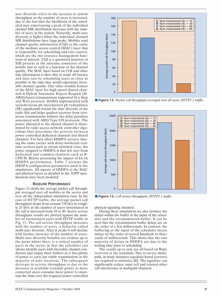
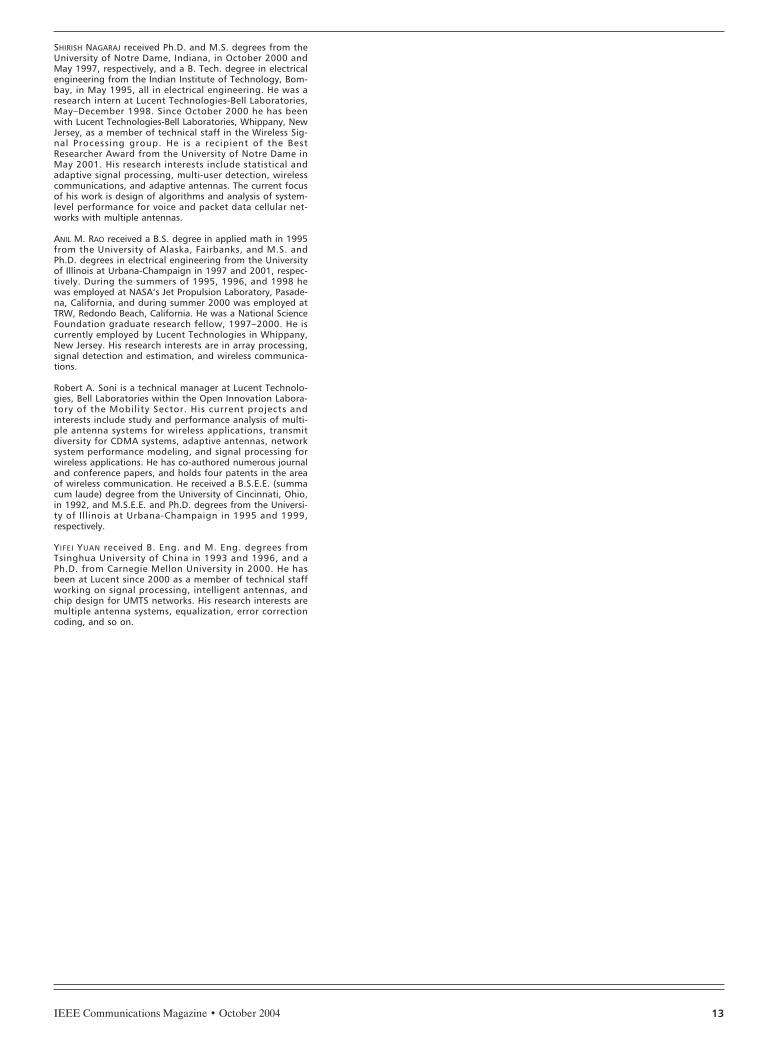
BASELINE PERFORMANCEFigure 12 shows the average packet call through-put averaged over all mobiles in the sector andover all the independent simulation runs. In thecase of HTTP traffic, the average packet callthroughput drops from around 170 kb/s to rough-ly 25 kb/s as the number of users instantiated inthe cell is increased from 10 to 80. Sector servicethroughput results are plotted against the num-ber of instantiated users with HTTP traffic inFig. 13. The cell service throughput increaseswith the number of users, a behavior calledmulti-user diversity. After it peaks it will declinewith further increase of the number of users.Multi-user diversity benefits are evident up tothe point where there is a critical number ofusers in the sector in that the scheduler canalways identify users with favorable channel con-ditions and empty their buffers as it has plentyof power to carry out viable transmissions in themajority of user locations. The subsequentdecrease in service throughput is due to thedecrease in available transmit power as moreconnected users consume more power to main-tain the links over the required power-controlled
physical signaling channels.During these simulations we also monitor the
delays within the buffer at the input of the sched-uler and the retransmission buffer. It can beseen that the retransmission buffer delays are onthe order of a few milliseconds. In contrast, thebuffering at the input of the scheduler incursdelays on the order of several hundreds to thou-sands of milliseconds. This shows that the vastmajority of delays in HSDPA are due to thewaiting time prior to scheduling.
The results up to now are all based on Rakereceivers at the terminals. Due to severe multi-path, in many instances equalizer-based receiversare required to minimize ISI. The equalizer cansignificantly reduce same cell and colored othercell interference in multipath channels.
� Figure 12. Packet call throughput averaged over all users; HTTP1.1 traffic.
0
20
Ave
rage
pac
ket
call
thro
ughp
ut (
kb/s
)
40
60
80
100
120
140
160
180Num instantiated UEs = 10Num instantiated UEs = 20Num instantiated UEs = 40Num instantiated UEs = 80
� Figure 13. Cell service throughput; HTTP1.1 traffic.
Num instantiated UEs = 10Num instantiated UEs = 20Num instantiated UEs = 40Num instantiated UEs = 80
0
500
Ave
rage
cel
l ser
vice
thr
ough
put
(kb/
s)
1000
1500
2000
2500

IEEE Communications Magazine • October 200410
THE ROLE OF TRANSMIT DIVERSITY
Transmit diversity techniques such as STTD,CLTD, and PSTD alter the individual SNR dis-tribution in a way that makes it more unlikelyfor a user to experience deep fades or high
peaks. This has a very desirable effect in dedicat-ed channels due to the fact that the user is notstuck in a deep fade very often. However, due tomulti-user diversity in scheduled shared data sys-tems, it is the peaks of the distribution, not thefades, that largely determine the total systemperformance. Moreover, in 3G shared data sys-tems such as HSDPA, other sources of diversityare available in the form of multipath propaga-tion and HARQ retransmissions, in addition tomulti-user diversity. Therefore, transmit diversitytechniques do not provide as much benefit inshared data systems as in dedicated channels.Transmit diversity techniques based on space-time coding, such as STTD, result in the averageof the SNR distribution being the same as withsingle antenna transmission. However, STTDshortens the tails of the distribution. With a suf-ficiently large number of users, this can actuallydegrade performance relative to single antennatransmission due to the reasons mentionedabove. Closed-loop transmit diversity techniquesthat are based on co-phasing the multiple anten-na signals, such as CLTD, also shorten the tailsof the SNR distribution. However, they alsoincrease the average SNR; thus, they offer somegain over single antenna transmission. Figure 14shows the beneficial effect of CLTD on averageservice throughput for Rake receivers.
The use of CLTD causes some side effects.The power allocated in shared packet data chan-nels is high enough that the common pilot SIR isaffected from time slot to time slot. This resultsin multipath channels in what is called CQI con-tamination, a phenomenon that can also beattributed to CLTD operation in nearby BSs. Asa result of this contamination, an increased num-ber of HARQ retransmissions have beenobserved that affects QoS. In addition, CLTDcan also affect the equalizer gain and/ormarginalize their benefit. The explanation ofthese losses has to do with equalizer training andare outside the scope of this article.
Finally, although PSTD does not necessarilyshorten the tails of the SNR distribution, whileincreasing its average, the existence of multi-userdiversity in addition to fading erodes any possi-ble gains of its use. The results of the applicationof PSTD are summarized in Fig. 15. Two anten-na configurations have been employed, DIV-1Xand ULA-2V. In the first case, there are essen-tially no gains even with very small Doppler fad-ing (3 km/h). With ULA-2V, the setup resemblesa rotating beam. Interestingly, in this case thecell service throughput is lowered for a largenumber of users, due to the fact that there is asignificant number of users away from the centerof the beam, resulting in reduced beamforminggains and higher delays. Similar results havebeen seen elsewhere [6].
CODE REUSE WITHBEAMFORMING ANTENNA CONFIGURATIONS
It is clear that a desirable multiple antennatransmission scheme should increase the averageSNR and not decrease SNR peaks. Beamform-ing with closely spaced antennas is one tech-nique that increases the average SNR without
� Figure 14. The benefit of CLTD compared to the single-input single-outputconfiguration on cell service throughput for the HTTP1.1 traffic model andRake UE receivers.
Number of instantiated UEs70 8010
1000
1500
Ave
rage
ser
vice
thr
ough
put
(kb/
s)
2000
2500
3000
3500
6050403020
SISO, rakeCLTD, rake
� Table 3. HSDPA simulation parameters.
Parameter Value and remarks
Simulation duration for each run 1000 s
Number of runs 600/number of instantiated UEs
Channel estimation Nonideal (P-CPICH-based)
Receiver type Rake or equalizer
Number of equalizer Tc/2 taps 12
Maximum transmit power in the cell 43 dBm
P-CPICH transmit power 31 dBm
Num. of HS-SCCHs/cell 4
HS-SCCH power offset 13dB over associated DPCH Tx power
Soft handoff Off
Associated DPCH ILPC On
Associated DPCH OLPC On
HSDPA UE category 6
No. of HARQ processes per UE 7
Criterion for termination of TSN sliding window in MAC-hs Txretransmissions for a MAC-hs PDU
MAC-hs Window size 8 (for both transmitter and receiver)
MAC-hs T1 UE timer 80 ms
MAC-hs scheduling algorithm Proportional Fairness
PF algorithm window size 1 s
Ack/Nack delay 5 TTI (10 ms)
CQI averaging window size 3 slots (2 ms)
CQI feedback delay 8 slots (5.33 ms)

IEEE Communications Magazine • October 2004 11
changing the shape of the distribution,4 thus notshortening the tails. Consequently, beamformingprovides a larger increase in system throughputthan transmit diversity techniques.
Although the SNR improvement due tobeamforming results in throughput enhance-ment, a more dramatic benefit comes from thefact that beamforming enables simultaneouslyscheduled users, separated spatially using beams,to share the same bandwidth (or codes) and splitthe available power. This is due to the fact thatwhile throughput increases logarithmically withSNR, it increases linearly with bandwidth. Wecan understand this with the help of the follow-ing idealized example. If the symbol rate is Rssymbols/s and there are W codes available, auser whose instantaneous SNR is ρ with a singleantenna transmission can achieve an instanta-neous rate of roughly WRs log (1 + ρ) b/s. Thesame user can roughly achieve an instantaneousrate of WRs log (1 + Nρ) with the help of beam-forming with N closely spaced antennas. If twosuch users split the available power in half andare spatially separated using beams formed withN transmit antennas, the combined throughputthey can achieve is 2WRs log (1 + Nρ/2), whichis larger than the one-user throughput withbeamforming. We shall refer to the technique ofscheduling multiple spatially separated userswith code reuse as multibeam scheduling (MBS).
In a practical system, gains from MBS aretempered by interference between beams due tooverlapping beam patterns and angle spreadseen at the BS. Our MBS solution for HSDPAinvolves optimal scheduling of users based onpriority, channel quality and spatial location, andoptimal power, bandwidth, and beam allocationto the scheduled users.
In order to evaluate the improvement in airinterface performance due to beamforming with-out constraints imposed by traffic models, thesimulation results presented next assume fullbuffers at the MAChs of all active users. Figure16 shows the average cell service throughput fordifferent numbers of users in the cell and differ-ent antenna technologies. All quantities, (cellthroughput and number of users) are scaled torefer to the area of one cell in a three-cell cellu-lar layout.
Figure 16 shows that fixed beamforming pro-vides 30–35 percent improvement in cell servicethroughput over that of single antenna transmis-sion. Also, a narrower element pattern with 65°beamwidth provides higher throughput than a90° pattern in a three-cell layout. The through-put per unit area from a six-cell layout with onetransmit antenna is slightly less than two timesthat from a three-cell layout with one transmitantenna. This can be explained as follows: whileantenna gain of the 33° pattern used in the six-cell layout roughly compensates for the 3 dBdecrease in the transmit power per cell, there iscomplete reuse of bandwidth between the twocells in a six-cell layout that correspond to onecell in the three-cell layout. Gains for individualusers can be inferred from Fig. 17, which showsthe probability distribution of user-perceived ser-vice throughput using different antenna tech-nologies.
The more striking result is that when MBSwith code reuse is used in a three-cell layout, itexploits code reuse without need for a six-celldeployment, and provides 80 percent improve-ment in cell and user throughputs over usingfixed beamforming without code reuse.
CONCLUSIONSWe have evaluated a wide range of IA deploy-ment scenarios based on practical antenna con-figurations that can significantly enhance thebaseline performance of UMTS in both uplinkand downlink. Extensive simulation results werepresented that verified the benefits of intelligentantennas to dedicated, connectionless, and
� Figure 15. The effects of various opportunistic beamforming (PSTD) config-urations on cell service throughput for no code multiplexing and a full buffertraffic model with Rake UE receivers.
Number of users in 120° area35 4010
1000
1200
Cel
l ser
vice
thr
ough
put
(kb/
s)
1400
1600
1800
2000
2200
2600
2800
2400
30252015
1 antennaPSTD freq = 2 Hz; BF configurationPSTD freq = 2 Hz; DIV configurationPSTD freq = 5 Hz; BF configurationPSTD freq = 5 Hz; DIV configuration
� Figure 16. Cell service throughput; full buffer traffic; Rake receiver.
Number of users in 120° area18 206
0
1000
Cel
l ser
vice
thr
ough
put
(kb/
s)
2000
3000
4000
5000
6000
7000
8000
9000
10000
161412108
3-cell, MBS, 5 beams3-cell, MBS, 4 beams6-cell, CLTD6-cell, 1 Tx3-cell, FxBF, 5 beams3-cell, FxBF, 4 beams3-cell, 1 Tx
4 This assumes that theangle spread seen at thebase station antenna arrayis small.

IEEE Communications Magazine • October 200412
HSPSD channels. Universal beamforming andmultibeam scheduling paired with RF optimiza-tion techniques in the field can significantlyimprove system capacity. The challenging prob-lem of implementing a practical IA solution suit-able for macrocellular environments wasaddressed by combining practical choices on theantenna configuration and innovative design onboth physical and MAC layer algorithms.
ACKNOWLEDGMENTSThe authors would like to thank Roger Benning,Paul Polakos, Kam Wu, and AndrewZaporozhets for their help and support.
REFERENCES[1] “Spatial Channel Model for Multiple-Input Multiple Out-
put Simulations,” 3GPP TR 25.996 v. 6.1.0, Sept. 2003.[2] R. A. Soni, R. M. Buehrer, and R. D. Benning, “An Intel-
ligent Antenna System for CDMA2000,” IEEE Trans. Sig.Proc., vol. 19, Jul. 2002, pp. 54–67.
[3] M. Gudmundson, “Correlation Model for Shadow Fad-ing in Mobile Radio Systems,” Elect. Lett., vol. 27, no.23, Nov. 1991, pp. 2145–46.
[4] “1xEV-DV Evaluation Methodology Rev. 26,” 3GPP2WG5 Eval. AHG, 2002.
[5] K. Pedersen, P. Mogensen, and J. Ramiro-Moreno,“Application and Performance of Downlink Beamform-ing Techniques in UMTS,” IEEE Commun. Mag., vol. 41,no. 10, Oct. 2003, pp. 134–43.
[6] M. Gurelli and R. H. Etkin, “Capacity Simulation ofCDMA2000 1xEV-DO Forward Link with OpportunisticBeam Forming,” IEEE GLOBECOM 2003, vol.2, Dec.2003, pp. 1136–40.
BIOGRAPHIESKEITH CONNER received a .B.S.E.E with honors from Missis-sippi State University, and his M.S.E.E. and Ph.D. fromClemson University. He works for the Open Innovation Lab-oratory of Lucent Technologies. His past work includesalgorithm research, network optimization, protocolenhancements, product development, and standards activi-ties in TDMA, GSM, GPRS, EDGE, and UMTS. He currentlydevelops efficient flexible software architectures for algo-rithm and product development and verification.
DEEPAK DAS [M] received a B.E. (Hons.) degree in electrical
and electronics engineering from the Birla Institute ofTechnology and Science, Pilani, India, in 1992, and M.S.and Ph.D. degrees in electrical and computer engineeringfrom the University of Colorado, Boulder, in 1997 and2000, respectively. From 1992 to 1995 he was a softwareconsultant with Mahindra-British Telecom, and worked atBritish Telecom, London, United Kingdom. He is currently amember of technical staff with the Open Innovation Labo-ratory, Lucent Technologies, Whippany, New Jersey. Hisresearch interests include wireless communications withfocus on multi-user detection, power control, intelligentantennas, and cross-layer optimization.
SRIDHAR GOLLAMUDI received a B.Tech. degree in electricalengineering from the Indian Institute of Technology, Bom-bay, in May 1994, and M.S.E.E. and Ph.D. degrees fromthe University of Notre Dame in January 1996 and May,2000, respectively. From May to December 1997 he was anintern at Lucent Technologies, Whippany, New Jersey,where he worked on interference suppression for wirelessCDMA systems. He was with the Advanced Receiver Devel-opment group at Motorola, Arlington Heights, Illinois,from October 1999 to November 2000. Since November2000 he has been with Lucent Technologies at Whippany,where he has worked on various signal processing andresource allocation aspects of 3G cellular networks. Hisresearch interests are in the areas of statistical and adap-tive signal processing, digital communications theory,space-time coding, multi-user communications, and anten-na array processing.
JUNG AH C. LEE received the B.S. and M.S. degrees in elec-tronics engineering from Seoul National University, Korea,in 1987 and 1989, respectively. From 1992 to 1997 shewas a research assistant at the Coordinated Science Labo-ratory, University of Illinois at Urbana-Champaign, whereshe received a Ph.D. degree in electrical and computerengineering in 1997. She is currently with Lucent Technolo-gies as a member of technical staff. Her research interestsare signal processing for wireless communication systems,image formation algorithms for synthetic aperture radar,and multidimensional signal processing.
PANTELIS MONOGIOUDIS ([email protected]) received hisPh.D. and M.Sc. from the University of Surrey, United King-dom, in 1994 and 1991, respectively. He received hisB.Eng. with honors degree from the Technological Educa-tional Institute (TEI) of Athens, Greece, in 1989. From 1991to 1993 he was a research scientist at Philips Research Lab-oratories, Redhill, United Kingdom. During this time heparticipated in the EU R& D project CODIT project that ledto the prototyping of Europe’s first W-CDMA prototypeaccess network and mobile terminal. Between 1994 and1996 he was with Intracom SA, Athens, Greece, where heworked on DECT radio local loop and EU funded projectsunder the ACTS R&D framework, such as RAINBOW andEXODUS. During this time he was also employed part-timeat the European Telecommunications Standards Institute(ETSI), Sophia Antipolis, France, as a technical wxpert inProject Team 10 that standardized DECT. In 1997 he joinedLucent Technologies where he served as a member of tech-nical staff, initially in the United Kingdom and subsequent-ly in Bell Laboratories, Holmdel, New Jersey. At Lucent heworked on the project that delivered W-CDMA prototypeequipment to NTT DoCoMo, and also various generationsof W-CDMA ASICs currently used in Lucent’s Node-B equip-ment. He currently works as a Distinguished Member ofTechnical Staff in Whippany New Jersey, where he isengaged in R&D projects related to HSDPA and IA tech-nologies. He has an extensive publication record and hasco-authored 21 patent applications (four granted) in thearea of wireless communications.
ARIS L. MOUSTAKAS [M’02] received a B.S. degree in physicsfrom the California Institute of Technology in 1990, andM.S. and Ph.D. degrees in theoretical condensed matterphysics from Harvard University in 1992 and 1996, respec-tively. In 1998, after a two-year stint in the Greek Navy, hejoined Bell Labs, Lucent Technologies, first in the PhysicalSciences Division in Murray Hill, New Jersey, and then alsoin the Wireless Advanced Technology Laboratory in Whip-pany, New Jersey. His current research interests lie in theareas of multiple antenna systems, signal processing forsmart antennas, and wideband channel modeling; he isparticularly interested in the applications of physical ideasto the theory of communications. He has authored severalpapers and patents on these topics.
� Figure 17. Statistics of user service throughput; full buffer traffic; Rake receiver.
Service throughput for each UE (kb/s)18000
0
0.1
CD
F
0.2
0.3
0.4
0.5
0.6
0.7
0.8
0.9
1
1600140012001000800600400200
3 cell, MBS, 5 beams3 cell, MBS, 4 beams6 cell, CLTD6 cell, 1Tx3 cell, FxBF, 5 beams3 cell, FxBS, 4 beams3 cell, 1 Tx
IEEE Communications Magazine • October 2004 13
SHIRISH NAGARAJ received Ph.D. and M.S. degrees from theUniversity of Notre Dame, Indiana, in October 2000 andMay 1997, respectively, and a B. Tech. degree in electricalengineering from the Indian Institute of Technology, Bom-bay, in May 1995, all in electrical engineering. He was aresearch intern at Lucent Technologies-Bell Laboratories,May–December 1998. Since October 2000 he has beenwith Lucent Technologies-Bell Laboratories, Whippany, NewJersey, as a member of technical staff in the Wireless Sig-nal Processing group. He is a recipient of the BestResearcher Award from the University of Notre Dame inMay 2001. His research interests include statistical andadaptive signal processing, multi-user detection, wirelesscommunications, and adaptive antennas. The current focusof his work is design of algorithms and analysis of system-level performance for voice and packet data cellular net-works with multiple antennas.
ANIL M. RAO received a B.S. degree in applied math in 1995from the University of Alaska, Fairbanks, and M.S. andPh.D. degrees in electrical engineering from the Universityof Illinois at Urbana-Champaign in 1997 and 2001, respec-tively. During the summers of 1995, 1996, and 1998 hewas employed at NASA’s Jet Propulsion Laboratory, Pasade-na, California, and during summer 2000 was employed atTRW, Redondo Beach, California. He was a National ScienceFoundation graduate research fellow, 1997–2000. He iscurrently employed by Lucent Technologies in Whippany,New Jersey. His research interests are in array processing,signal detection and estimation, and wireless communica-tions.
Robert A. Soni is a technical manager at Lucent Technolo-gies, Bell Laboratories within the Open Innovation Labora-tory of the Mobility Sector. His current projects andinterests include study and performance analysis of multi-ple antenna systems for wireless applications, transmitdiversity for CDMA systems, adaptive antennas, networksystem performance modeling, and signal processing forwireless applications. He has co-authored numerous journaland conference papers, and holds four patents in the areaof wireless communication. He received a B.S.E.E. (summacum laude) degree from the University of Cincinnati, Ohio,in 1992, and M.S.E.E. and Ph.D. degrees from the Universi-ty of Illinois at Urbana-Champaign in 1995 and 1999,respectively.
YIFEI YUAN received B. Eng. and M. Eng. degrees fromTsinghua University of China in 1993 and 1996, and aPh.D. from Carnegie Mellon University in 2000. He hasbeen at Lucent since 2000 as a member of technical staffworking on signal processing, intelligent antennas, andchip design for UMTS networks. His research interests aremultiple antenna systems, equalization, error correctioncoding, and so on.