intelligent risk assessment for dewatering of metro...
TRANSCRIPT
Hindawi Publishing CorporationMathematical Problems in EngineeringVolume 2012, Article ID 618979, 13 pagesdoi:10.1155/2012/618979
Research ArticleIntelligent Risk Assessment for Dewatering ofMetro-Tunnel Deep Excavations
X. W. Ye,1 L. Ran,2 T. H. Yi,3 and X. B. Dong2
1 Institute of Transportation Engineering, College of Civil Engineering and Architecture,Zhejiang University, Hangzhou 310058, China
2 Hangzhou Metro Group Co., Ltd., Hangzhou 310020, China3 Research Center for Structural Health Monitoring and Control, School of Civil Engineering,Dalian University of Technology, Dalian 116023, China
Correspondence should be addressed to T. H. Yi, [email protected]
Received 14 October 2012; Accepted 4 November 2012
Academic Editor: Sheng-yong Chen
Copyright q 2012 X. W. Ye et al. This is an open access article distributed under the CreativeCommons Attribution License, which permits unrestricted use, distribution, and reproduction inany medium, provided the original work is properly cited.
In recent years, China has been undergoing ametro railway construction boom in order to alleviatethe urban traffic congestion problem resulting from the rapid urbanization and population growthin many metropolises. In the construction of metro systems, deep excavations and continuousdewatering for construction of the metro tunnels and stations remain a challenging and high risktask in densely populated urban areas. Intelligent computational methods and techniques haveexhibited the exceptional talent in dealing with the complicated problems inherent in the deepexcavation and dewatering practice. In this paper, an intelligent risk assessment system for deepexcavation dewatering is developed and has been applied in the project of HangzhouMetro Line 1which is the first metro line of the urban rapid rail transit system in Hangzhou, China. The specificcharacteristics and great challenges in deep excavation dewatering of the metro-tunnel airshaftof Hangzhou Metro Line 1 are addressed. A novel design method based on the coupled three-dimensional flow theory for dewatering of the deep excavation is introduced. The modularlydesigned system for excavation dewatering risk assessment is described, and the field observationsin dewatering risk assessment of the airshaft excavation of Hangzhou Metro Line 1 are also pre-sented.
1. Introduction
With the rapid expansion of industrialization and urbanization, traffic congestion has becomea serious social problem in most of the large cities in China. Establishment of a large-scalemetro network has been recognized to be a most effective way in alleviating the urban trafficcongestion problem [1, 2]. In recent years, a large amount of metro railway construction
2 Mathematical Problems in Engineering
accompanied by deep excavations in densely populated areas has been undergone in themetropolises of China. For the metro-tunnel excavation to be opened below the groundwaterlevel, a reasonable and robust dewatering system is always desired to obtain the requiredworking condition during the excavation construction period. An effective and efficientdewatering system can be achieved through the integration of groundwater flow modeling,inverse simulation analysis, and optimization formulation to minimize the total amount ofwater pumpage or implementation cost while satisfying the design criteria [3–5].
It has been well known that the dewatering of the confined aquifer for deep exca-vations may bring adverse impacts on the surrounding buildings and environments, suchas consolidation and compression of the soil layers, settlement and deformation of the piles,cracking and inclination of the buildings, and so forth [6]. Therefore, it becomes essential anddesirable to investigate the hydraulic characteristics of deep excavation dewatering as wellas the interactions of the underground continuous wall, the seepage well, and the soil layers,which have attracted a great deal of academic and industrial attention from numerousinvestigators and practitioners worldwide [7–11].
Chen and Xiang [12] proposed a procedure for estimation of dewatering-induced pilesettlement through four steps including a pumping model, a simplified consolidation evalua-tion, a pile-soil interaction model, and a semitheoretical pile settlement prediction. Schroederet al. [13] presented the practice of planning and execution of dewatering for a deep excava-tion in coarse alluvium containing cobbles and boulders. Wang et al. [14] developed a deci-sion support system for dewatering systems selection (DSSDSS) for determination of themost appropriate dewatering system for a project. Forth [15] reported the groundwater con-trol for deep excavations and geotechnical aspects in Hong Kong.
Up to now, a set of nature-inspired computational methodologies and approaches,such as artificial neural networks, fuzzy logic systems, genetic algorithms, and so forth, havebeen developed and are being powerful tools for quantitatively identifying the constitutiveparameters and solving the optimization problems in various engineering fields [16–23]. Inthis study, an intelligent risk assessment system for deep excavation dewatering construc-tion is developed with integration of the novel computational intelligence and has beenexemplified to implement dewatering risk assessment of the airshaft excavation of HangzhouMetro Line 1.
2. Deep Excavation Dewatering of Metro-Tunnel Airshaft
2.1. Metro-Tunnel Airshaft
Hangzhou Metro Line 1 is the first metro line of the urban rapid rail transit system inHangzhou, China, which is one of the largest municipal projects of Hangzhou and is beingconstructed starting from 28 March 2007 and will be officially put into operation in the endof October 2012. This metro line has a total length of 48 km and 34 stations, connectingHangzhou downtown with suburban area of the city. It starts from the south at the XianghuStation in Xiaoshan District, stretches northwards to the Binjiang Station adjacent to theQiantang River, crosses beneath the Qiantang River to the Fuchun Road Station, passesthrough Hangzhou downtown, and ends in the Linping Station, with a branch line ending inXiasha District which diverges from the main line at the Jiubao Station. The 2nd constructionsegment of Hangzhou Metro Line 1 covers from the Binjiang Station to the Jiubao Stationwith a length of 25 km. In this construction section, a two-lane single-bore shield tunnel has
Mathematical Problems in Engineering 3
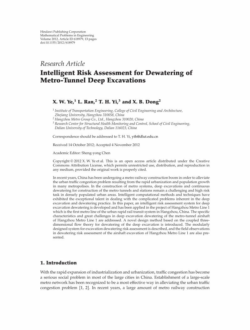
BinjiangStation
Metro tunnelQiantang River
Northern airshaft Southern airshaft
Fuchun RoadStation
Figure 1: River-crossing metro tunnel and airshafts.
been constructed under the Qiantang River to link the Binjiang Station and the Fuchun RoadStation, with two airshafts (the southern airshaft and the northern airshaft) being settled atboth sides of the Qiantang River, as illustrated in Figure 1.
2.2. Dewatering of Airshaft Excavation
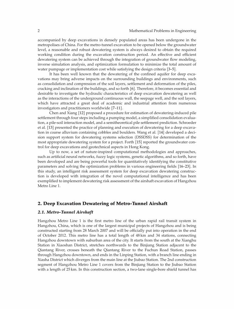
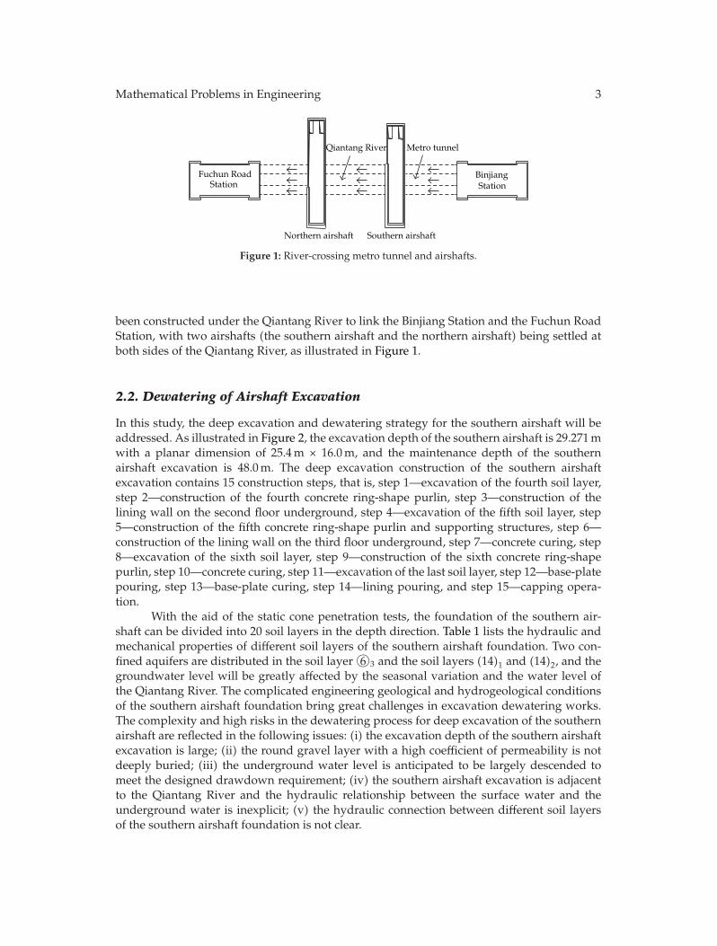
In this study, the deep excavation and dewatering strategy for the southern airshaft will beaddressed. As illustrated in Figure 2, the excavation depth of the southern airshaft is 29.271mwith a planar dimension of 25.4m × 16.0m, and the maintenance depth of the southernairshaft excavation is 48.0m. The deep excavation construction of the southern airshaftexcavation contains 15 construction steps, that is, step 1—excavation of the fourth soil layer,step 2—construction of the fourth concrete ring-shape purlin, step 3—construction of thelining wall on the second floor underground, step 4—excavation of the fifth soil layer, step5—construction of the fifth concrete ring-shape purlin and supporting structures, step 6—construction of the lining wall on the third floor underground, step 7—concrete curing, step8—excavation of the sixth soil layer, step 9—construction of the sixth concrete ring-shapepurlin, step 10—concrete curing, step 11—excavation of the last soil layer, step 12—base-platepouring, step 13—base-plate curing, step 14—lining pouring, and step 15—capping opera-tion.
With the aid of the static cone penetration tests, the foundation of the southern air-shaft can be divided into 20 soil layers in the depth direction. Table 1 lists the hydraulic andmechanical properties of different soil layers of the southern airshaft foundation. Two con-fined aquifers are distributed in the soil layer �6 3 and the soil layers (14)1 and (14)2, and thegroundwater level will be greatly affected by the seasonal variation and the water level ofthe Qiantang River. The complicated engineering geological and hydrogeological conditionsof the southern airshaft foundation bring great challenges in excavation dewatering works.The complexity and high risks in the dewatering process for deep excavation of the southernairshaft are reflected in the following issues: (i) the excavation depth of the southern airshaftexcavation is large; (ii) the round gravel layer with a high coefficient of permeability is notdeeply buried; (iii) the underground water level is anticipated to be largely descended tomeet the designed drawdown requirement; (iv) the southern airshaft excavation is adjacentto the Qiantang River and the hydraulic relationship between the surface water and theunderground water is inexplicit; (v) the hydraulic connection between different soil layersof the southern airshaft foundation is not clear.
4 Mathematical Problems in Engineering
25400 15600
Accessory structure
1600
0
1 2 3 4
W12-14
W12-1 W12-2 W12-3 W12-4 W12-5 W12-6 W6-1 W6-2 W6-3
W6-6W6-7W6-8
W6-
4W
6-5
W12
-15
W12
-16
W12-13 W12-12 W12-11 W12-10 W12-9
W12
-8W
12-7
Shield area
(a) Plan view
4800
0
2927
118
729
(b) Cross-sectional view
Figure 2: Schematic of southern airshaft excavation (unit: mm).

Mathematical Problems in Engineering 5
Table 1: Hydraulic and mechanical properties of soil layers of southern airshaft foundation.
No. Soil layer Thickness of soil layer(m)
Coefficient ofpermeability (cm/s)
Modulus ofcompressibility (MPa)
�1 1 Miscellaneous fill soil 0.70 ∼ 3.10 5.0E − 03 —�1 2 Plain fill soil 0.30 ∼ 6.00 8.0E − 04 6.5�3 1 Sandy silt 3.4 4.0E − 04 7.0�3 2 Sandy silt 3.50 ∼ 9.70 7.0E − 04 8.5�3 4 Sandy silt 1.00 ∼ 5.90 6.5E − 04 5.5�3 5 Silty sand and sandy silt 1.60 ∼ 7.00 3.0E − 03 7.0�3 6 Silt 4.20 ∼ 10.95 4.0E − 03 10.0�3 7 Sandy silt 0.80 ∼ 6.20 2.0E − 04 5.5�3 8 Silt — 4.5E − 03 10.5�4 3 Silty soft clay 2.60 ∼ 6.70 3.0E − 06 2.6�6 1 Silty soft clay 1.50 ∼ 3.70 2.0E − 06 2.7�6 2 Silty soft clay 1.00 ∼ 8.30 5.0E − 06 2.8�6 3 Silt 0.50 ∼ 3.85 3.0E − 03 8.0�8 2 Silty soft clay 0.80 ∼ 8.20 4.0E − 05 3.0�8 3 Silty-fine sand 1.80 ∼ 8.50 5.0E − 03 8.5�10 1 Silty clay 1.90 ∼ 4.30 8.0E − 06 3.2
�10 2 Silty clay 2.80 ∼ 4.60 4.0E − 06 4.5(14)1 Medium sand — 6.0E − 03 11.0(14)2 Rounded pebble — 3.5E − 01 —
3. Intelligent Dewatering Risk Assessment System
3.1. Novel Design Method of Deep Excavation Dewatering
During the dewatering process of the deep excavation, one of the key problems is how tohandle the issue of confined water decompression which is the most critical risk sources inthe deep excavation practices. Currently existent design methods for dewatering of the deepexcavation are primarily based on the theory of groundwater dynamics and have the fol-lowing limitations: (i) the existing design methods for dewatering of the deep excavationare originated from the water supply theory and have not sufficiently taken into account thefunction of the waterproof curtain of the supporting structure; (ii) the empirical equations orthe analytical methods are mainly adopted in the existing design methods for dewatering ofthe deep excavation with the fact of ignoring the detouring flow effect of the undergroundwall; (iii) both the anisotropic property of the soil layer and the three-dimensional flow effectof the partially penetrating well near the underground wall are neglected in the existingdesign methods for dewatering of the deep excavation.
For deep excavation construction of the southern airshaft of Hangzhou Metro Line 1,the traditional dewatering method is lack of robustness in fulfilling the targeted drawdownrequirement. In this connection, a novel design method based on the coupled three-dimen-sional flow theory for dewatering of the airshaft excavation is developed in recognition thatthe implementation of the full waterproof curtain is highly difficult and costly. In the pro-posed method, the coupling effects amongst the underground continuous wall, the seepage
6 Mathematical Problems in Engineering
Excavation conditions
Excavation depth
Penetration depth of underground wall
Maintenance depth of underground wall
- -
resisting layerHydraulic properties Mechanical properties
Conceptual model
Field experiment Settlement monitoring
Settlement analysis of surrounding environment
Technical design parameters of confined water decompression and surrounding environment control
Construction technology of confined water decompression and
surrounding environment control
Project applications and market promotion
Engineering hydrogeological conditions
Structure of water Structure of waterbearing layer
Water-level monitoring
3D numerical simulation and inverse analysis
3D numerical simulation and forward analysis
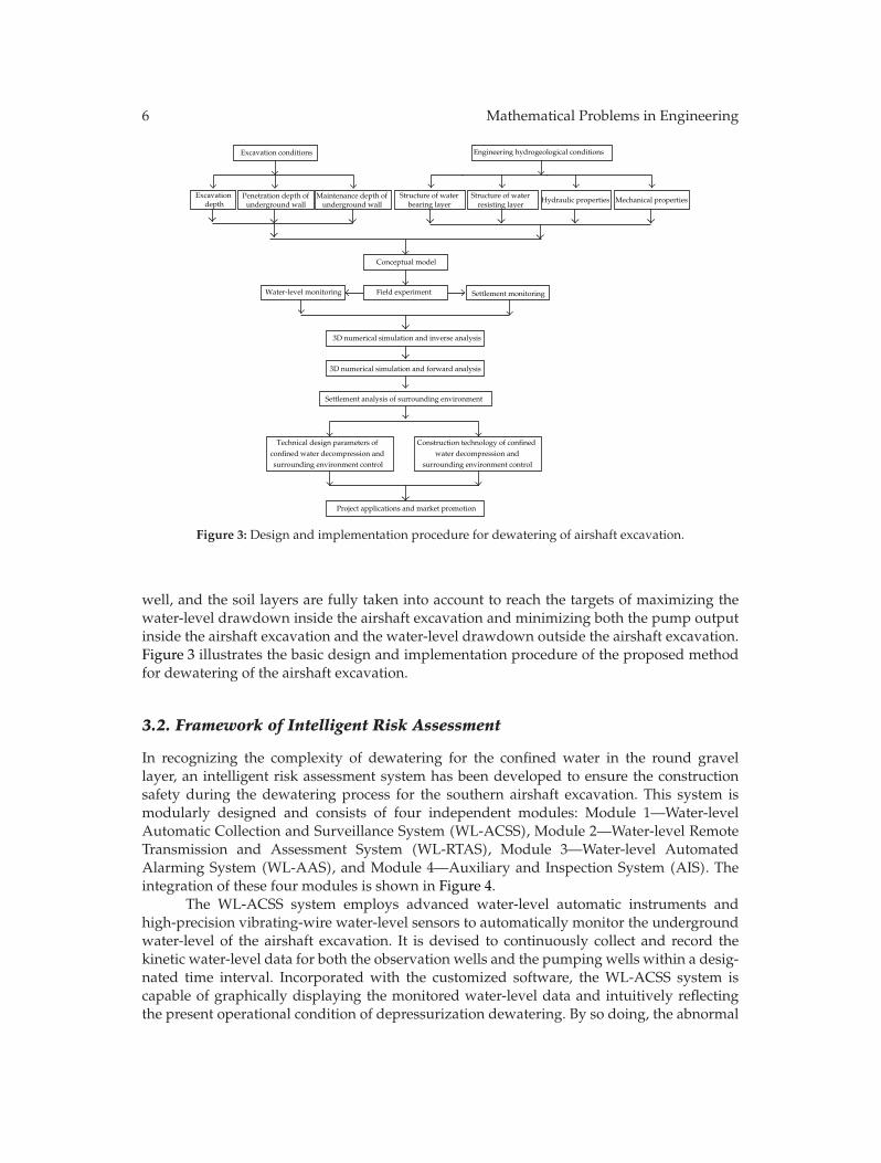
Figure 3: Design and implementation procedure for dewatering of airshaft excavation.
well, and the soil layers are fully taken into account to reach the targets of maximizing thewater-level drawdown inside the airshaft excavation and minimizing both the pump outputinside the airshaft excavation and the water-level drawdown outside the airshaft excavation.Figure 3 illustrates the basic design and implementation procedure of the proposed methodfor dewatering of the airshaft excavation.
3.2. Framework of Intelligent Risk Assessment
In recognizing the complexity of dewatering for the confined water in the round gravellayer, an intelligent risk assessment system has been developed to ensure the constructionsafety during the dewatering process for the southern airshaft excavation. This system ismodularly designed and consists of four independent modules: Module 1—Water-levelAutomatic Collection and Surveillance System (WL-ACSS), Module 2—Water-level RemoteTransmission and Assessment System (WL-RTAS), Module 3—Water-level AutomatedAlarming System (WL-AAS), and Module 4—Auxiliary and Inspection System (AIS). Theintegration of these four modules is shown in Figure 4.
The WL-ACSS system employs advanced water-level automatic instruments andhigh-precision vibrating-wire water-level sensors to automatically monitor the undergroundwater-level of the airshaft excavation. It is devised to continuously collect and record thekinetic water-level data for both the observation wells and the pumping wells within a desig-nated time interval. Incorporated with the customized software, the WL-ACSS system iscapable of graphically displaying the monitored water-level data and intuitively reflectingthe present operational condition of depressurization dewatering. By so doing, the abnormal

Mathematical Problems in Engineering 7
Transmission and Assessment SystemModule 1: Water level Automatic
Collection and Surveillance SystemModule 2: Water level Remote
Module 4: Auxiliary and InspectionSystem Alarming System
Module 3: Water level Automated
Figure 4: Modular architecture of intelligent risk assessment system.
phenomenon during the dewatering for the airshaft excavation could be readily seized andsurveilled in real time to facilitate decision making on timely actions in the event of anemergency.
The WL-RTAS system compiles the monitored water-level data acquired by the WL-ACSS system and generates the specified files suitable for remote transmission throughtethered and/or wireless networks. Once the client computers receive the transmitted files,the real-time water-level data will be evaluated with the aid of the coupled three-dimensionalflow model which can be expressed by
∂
∂x
(kxx
∂h
∂x
)+
∂
∂y
(kyy
∂h
∂y
)+
∂
∂z
(kzz
∂h
∂z
)−W = Ss
∂h
∂t,
kxx∂h
∂nx+ kyy
∂h
∂ny+ kzz
∂h
∂nz
∣∣∣∣∣Γ2
= q(x, y, z, t
),
h(x, y, z, t
)∣∣t=t0
= h0(x, y, z
),
(3.1)
where kxx, kyy, and kzz represent the coefficients of permeability in x, y, and z direction,respectively; h is the water head in time t; W is the source/sink term; Ss is the water storagerate; Γ2 is the boundary condition; nx, ny, and nz denote the unit vectors of the external nor-mal lines along x, y, and z directions, respectively; q is the water recharge per unit area.
The WL-AAS system includes the water-level anomaly alarming system and thepower-supply interruption alarming system. For the water-level anomaly alarming system,the warning facilities are allocated at the wellheads and the control room for generatingthe alarm bumming with light signals. The dynamic variation of the water-level of the air-shaft excavation will be tracked and the alarm trigger will be activated once the abnormalwater-level is identified by use of a novel threshold detection algorithm. The power-supplyinterruption alarming system will promptly notify the site managers to inspect or switch theelectric circuits when the power goes out.
The AIS system provides the accessory equipment for the intelligent risk assessmentsystem and a laptop-computer-aided portable system for inspecting andmaintaining sensors,data acquisition units, and cable networks.
8 Mathematical Problems in Engineering
S2S1
S4 S3
25400 15600
63006300 87008700
1600
0
7700
4300
4300
7700
1480
0
Y1
Y3
G1
Y4
Y2
YGl
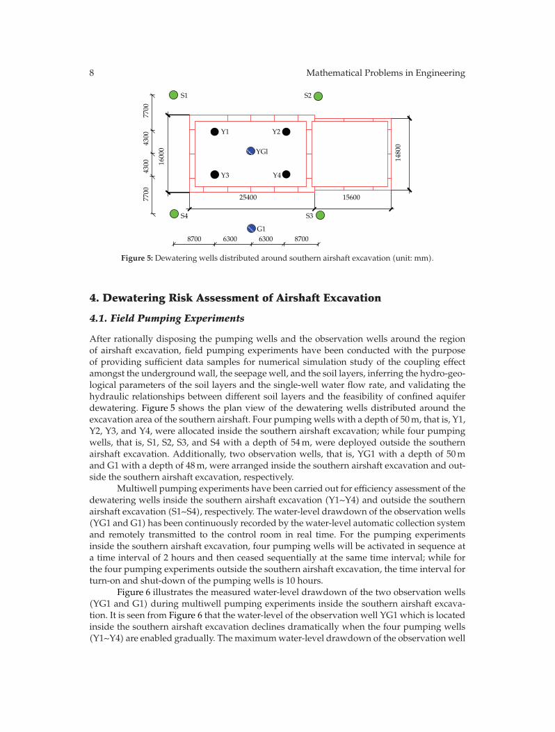
Figure 5: Dewatering wells distributed around southern airshaft excavation (unit: mm).
4. Dewatering Risk Assessment of Airshaft Excavation
4.1. Field Pumping Experiments
After rationally disposing the pumping wells and the observation wells around the regionof airshaft excavation, field pumping experiments have been conducted with the purposeof providing sufficient data samples for numerical simulation study of the coupling effectamongst the undergroundwall, the seepage well, and the soil layers, inferring the hydro-geo-logical parameters of the soil layers and the single-well water flow rate, and validating thehydraulic relationships between different soil layers and the feasibility of confined aquiferdewatering. Figure 5 shows the plan view of the dewatering wells distributed around theexcavation area of the southern airshaft. Four pumping wells with a depth of 50m, that is, Y1,Y2, Y3, and Y4, were allocated inside the southern airshaft excavation; while four pumpingwells, that is, S1, S2, S3, and S4 with a depth of 54m, were deployed outside the southernairshaft excavation. Additionally, two observation wells, that is, YG1 with a depth of 50mand G1 with a depth of 48m, were arranged inside the southern airshaft excavation and out-side the southern airshaft excavation, respectively.
Multiwell pumping experiments have been carried out for efficiency assessment of thedewatering wells inside the southern airshaft excavation (Y1∼Y4) and outside the southernairshaft excavation (S1∼S4), respectively. The water-level drawdown of the observation wells(YG1 and G1) has been continuously recorded by the water-level automatic collection systemand remotely transmitted to the control room in real time. For the pumping experimentsinside the southern airshaft excavation, four pumping wells will be activated in sequence ata time interval of 2 hours and then ceased sequentially at the same time interval; while forthe four pumping experiments outside the southern airshaft excavation, the time interval forturn-on and shut-down of the pumping wells is 10 hours.
Figure 6 illustrates the measured water-level drawdown of the two observation wells(YG1 and G1) during multiwell pumping experiments inside the southern airshaft excava-tion. It is seen from Figure 6 that the water-level of the observation well YG1 which is locatedinside the southern airshaft excavation declines dramatically when the four pumping wells(Y1∼Y4) are enabled gradually. The maximumwater-level drawdown of the observation well

Mathematical Problems in Engineering 9
0
5
10
15
20
0 500 1000 1500 2000
YG1G1
Wat
er-l
evel
dra
wd
own
(m)
Time (min)
Figure 6: Water-level drawdown of observation wells during multiwell pumping experiments insidesouthern airshaft excavation.
0
0.5
1
1.5
2
2.5
3
0
YG1G1
120
240
360
480
600
720
840
960
1200
1320
1440
1560
1680
1800
1920
2040
2160
2280
2400
2520
2640
2760
2880
3000
1080
Time (min)
Wat
er-l
evel
dra
wd
own
(m)
Figure 7: Water-level drawdown of observation wells during multiwell pumping experiments outsidesouthern airshaft excavation.
YG1 reaches 18.00m which is larger than the targeted water-level drawdown of 11.72m.On the other hand, the water-level of the observation well G1 outside the southern airshaftexcavation declines slowly and the maximum water-level drawdown of the observation wellG1 is only 1.92m. The main reason for the great difference of water-level drawdown betweenthe two observation wells is because the underground continuous wall obstructs the hyd-raulic connection between the confined aquifers inside and outside the southern airshaftexcavation.
Figure 7 shows the measured water-level drawdown of the two observation wells(YG1 and G1) during multiwell pumping experiments outside the southern airshaft excava-tion. It is observed from Figure 7 that the water-levels of the two observation wells declinealmost synchronously. The maximum water-level drawdown of the two observation wellsis 2.75m which is much less than the targeted water-level drawdown of 11.72m. Therefore,
10 Mathematical Problems in Engineering
Conceptual model
Numerical modeling Numerical experimentsField pumping experiments
Excavation depth
Supporting structur
Surrounding environment
Geological parameters
Inverse numerical analysis Experimental scenarios
Insertion depth of underground continuous wall
Water output volume
Dewatering optimization design
Hydrogeologicalparameters
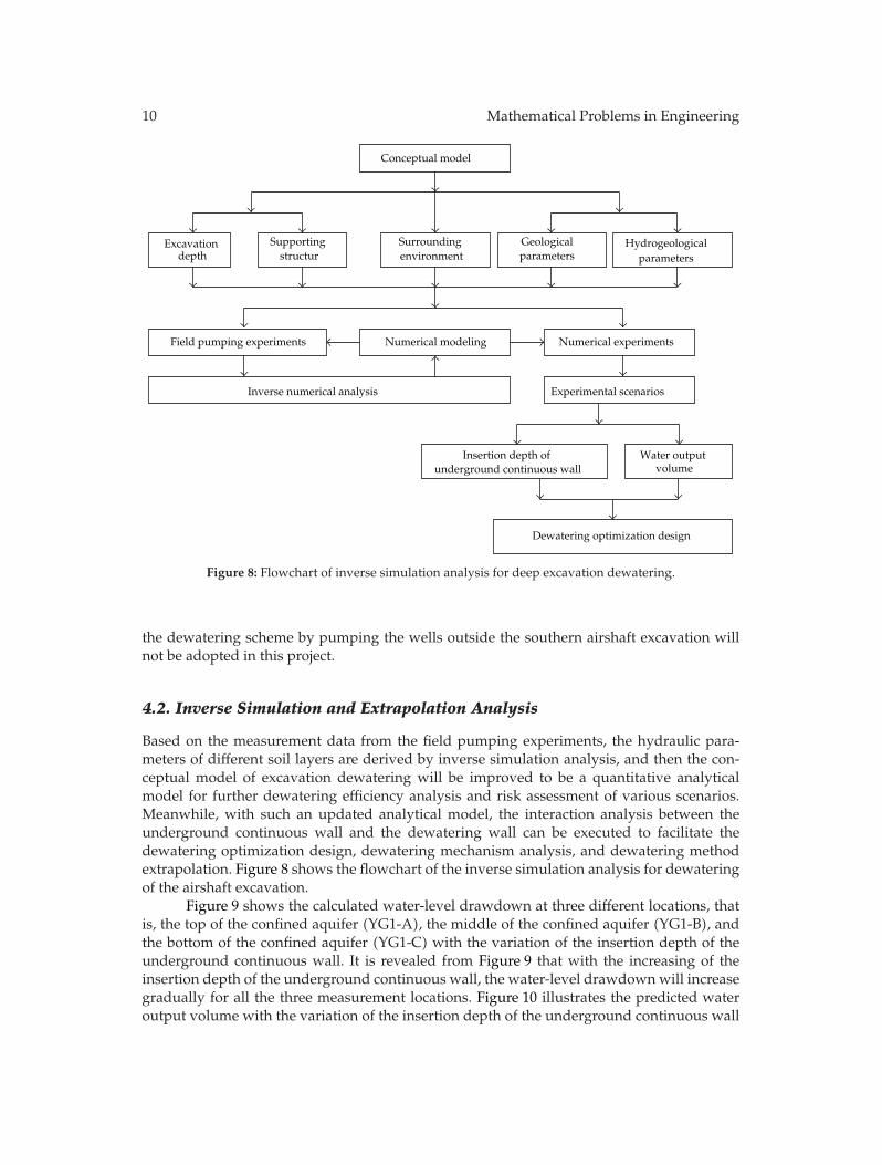
Figure 8: Flowchart of inverse simulation analysis for deep excavation dewatering.
the dewatering scheme by pumping the wells outside the southern airshaft excavation willnot be adopted in this project.
4.2. Inverse Simulation and Extrapolation Analysis
Based on the measurement data from the field pumping experiments, the hydraulic para-meters of different soil layers are derived by inverse simulation analysis, and then the con-ceptual model of excavation dewatering will be improved to be a quantitative analyticalmodel for further dewatering efficiency analysis and risk assessment of various scenarios.Meanwhile, with such an updated analytical model, the interaction analysis between theunderground continuous wall and the dewatering wall can be executed to facilitate thedewatering optimization design, dewatering mechanism analysis, and dewatering methodextrapolation. Figure 8 shows the flowchart of the inverse simulation analysis for dewateringof the airshaft excavation.
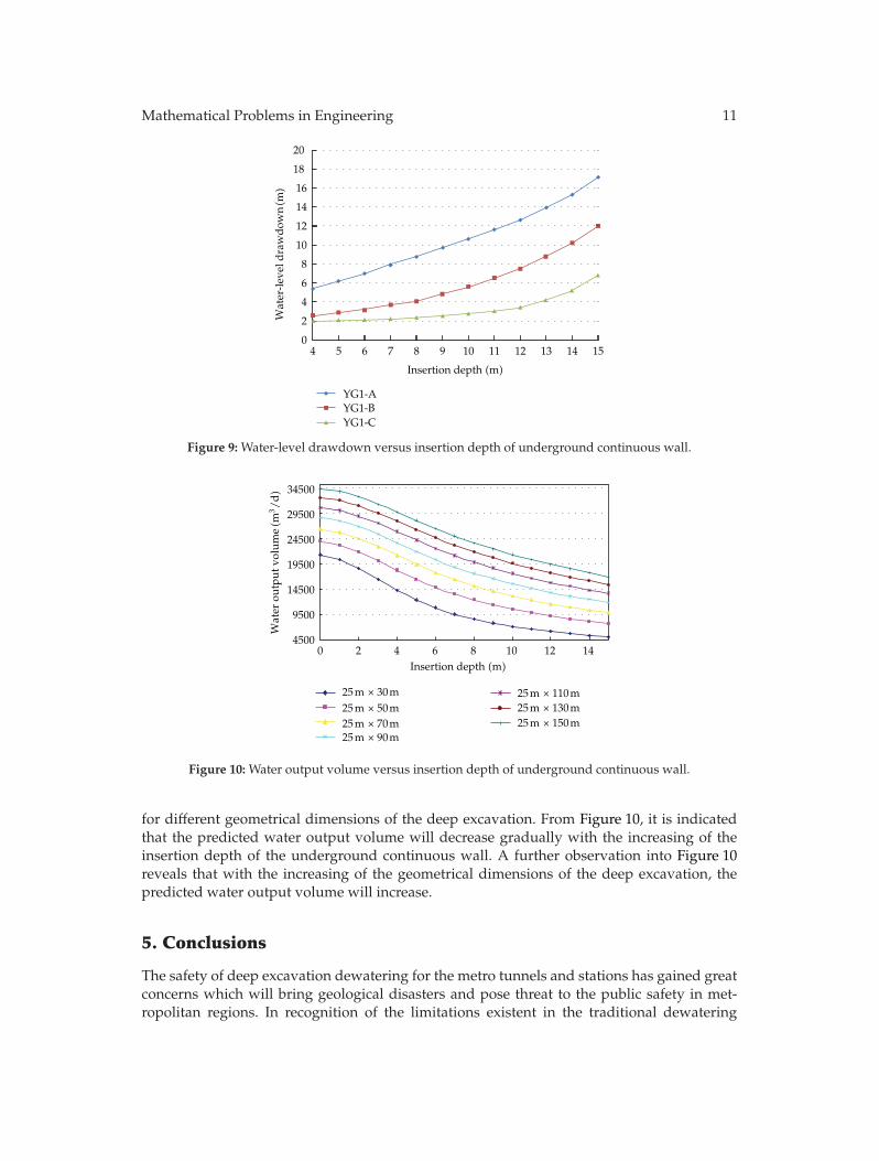
Figure 9 shows the calculated water-level drawdown at three different locations, thatis, the top of the confined aquifer (YG1-A), the middle of the confined aquifer (YG1-B), andthe bottom of the confined aquifer (YG1-C) with the variation of the insertion depth of theunderground continuous wall. It is revealed from Figure 9 that with the increasing of theinsertion depth of the underground continuous wall, the water-level drawdown will increasegradually for all the three measurement locations. Figure 10 illustrates the predicted wateroutput volume with the variation of the insertion depth of the underground continuous wall
Mathematical Problems in Engineering 11
0
2
4
6
8
10
12
14
16
18
20
4 5 6 7 8 9 10 11 12 13 14 15
YG1-AYG1-BYG1-C
Insertion depth (m)
Wat
er-l
evel
dra
wd
own(m
)
Figure 9: Water-level drawdown versus insertion depth of underground continuous wall.
4500
9500
14500
19500
24500
29500
34500
0 2 4 6 8 10 12 14
25 m × 30 m 25 m × 110 m25 m × 130 m25 m × 150 m
25 m × 50 m25 m × 70 m25 m × 90 m
Insertion depth (m)
Wat
er o
utpu
t vol
ume(m
3 /d)
Figure 10: Water output volume versus insertion depth of underground continuous wall.
for different geometrical dimensions of the deep excavation. From Figure 10, it is indicatedthat the predicted water output volume will decrease gradually with the increasing of theinsertion depth of the underground continuous wall. A further observation into Figure 10reveals that with the increasing of the geometrical dimensions of the deep excavation, thepredicted water output volume will increase.
5. Conclusions
The safety of deep excavation dewatering for the metro tunnels and stations has gained greatconcerns which will bring geological disasters and pose threat to the public safety in met-ropolitan regions. In recognition of the limitations existent in the traditional dewatering
12 Mathematical Problems in Engineering
method, a novel design method for excavation dewatering has been developed on the basisof the coupled three-dimensional flow theory. An intelligent risk assessment system has beendeveloped in modular architecture and applied to evaluate the safety of excavation dewater-ing for the metro-tunnel airshaft of Hangzhou Metro Line 1.
In this study, the following specific conclusions are drawn: (i) there is a great differenceof water-level drawdown between the observation well inside the airshaft excavation andthat outside the airshaft excavation during multiwell pumping experiments inside the air-shaft excavation; this is because the underground continuous wall obstructs the hydraulicconnection between the confined aquifers inside and outside the airshaft excavation; (ii)the water-level drawdown results of the observation wells during multiwell pumping expe-riments outside the airshaft excavation reveal that the dewatering scheme by pumping thewells outside the airshaft excavation is inappropriate; (iii) with the increasing of the inser-tion depth of the underground continuous wall, the water-level drawdown will increase gra-dually while the predicted water output volume will decrease.
Acknowledgments
This research work was jointly supported by the Science Fund for Creative Research Groupsof the NSFC (Grant no. 51121005), the National Natural Science Foundation of China (Grantno. 51178083, 51222806), and the Program for New Century Excellent Talents in University(Grant no. NCET-10-0287). The authors also wish to express their thanks to the HangzhouMetro Group Co., Ltd., for permission to publish this paper.
References
[1] Y. Y. Kim and K. K. Lee, “Disturbance of groundwater table by subway construction in the Seoul area,Korea,” Geosciences Journal, vol. 7, no. 1, pp. 37–46, 2003.
[2] J. C. Ni and W. C. Cheng, “Shield machine disassembly in grouted soils outside the ventilation shaft:a case history in Taipei Rapid Transit System (TRTS),” Tunnelling and Underground Space Technology,vol. 26, no. 2, pp. 435–443, 2011.
[3] M. Tokgoz, K. K. Yilmaz, and H. Yazicigil, “Optimal aquifer dewatering schemes for excavation ofcollector line,” Journal of Water Resources Planning and Management, vol. 128, no. 4, pp. 248–261, 2002.
[4] D. Roy and K. E. Robinson, “Surface settlements at a soft soil site due to bedrock dewatering,” Engi-neering Geology, vol. 107, no. 3-4, pp. 109–117, 2009.
[5] K. Demirbas, A. B. Altan-Sakarya, and H. Onder, “Optimal dewatering of an excavation site,” Pro-ceedings of the Institution of Civil Engineers. Water Management, vol. 165, no. 6, pp. 327–337, 2012.
[6] N. Zhou, P. A. Vermeer, R. Lou, Y. Tang, and S. Jiang, “Numerical simulation of deep foundation pitdewatering and optimization of controlling land subsidence,” Engineering Geology, vol. 114, no. 3-4,pp. 251–260, 2010.
[7] M. Preene and W. Powrie, “Steady-state performance of construction dewatering systems in finesoils,” Geotechnique, vol. 43, no. 2, pp. 191–205, 1993.
[8] W. Powrie and T. O. L. Roberts, “Case history of a dewatering and recharge system in chalk,” Geo-technique, vol. 45, no. 4, pp. 599–609, 1995.
[9] C. I. Mansur and S. G. Durrett, “Dewatering cofferdam for construction of Olmsted Locks,” Journal ofGeotechnical and Geoenvironmental Engineering, vol. 128, no. 6, pp. 496–510, 2002.
[10] A. Aryafar and F. D. Ardejani, “Anisotropy and bedding effects on the hydro geological regime in aconfined aquifer to design an appropriate dewatering system,” International Journal of EnvironmentalScience and Technology, vol. 6, no. 4, pp. 563–570, 2009.
[11] M. A. Bevan, W. Powrie, and T. O. L. Roberts, “Influence of large-scale inhomogeneities on a cons-truction dewatering system in chalk,” Geotechnique, vol. 60, no. 8, pp. 635–649, 2010.
[12] S. Chen and Y. Xiang, “A procedure for theoretical estimation of dewatering-induced pile settlement,”Computers and Geotechnics, vol. 33, no. 4-5, pp. 278–282, 2006.
Mathematical Problems in Engineering 13
[13] W. L. Schroeder, V.W. Rybel, and L. Cochran, “Dewatering for Opal Springs Powerhouse excavation,”Journal of Construction Engineering and Management, vol. 112, no. 3, pp. 440–451, 1986.
[14] S. Q. Wang, Y. P. Wee, and G. Ofori, “DSSDSS: a decision support system for dewatering systemsselection,” Building and Environment, vol. 37, no. 6, pp. 625–645, 2002.
[15] R. A. Forth, “Groundwater and geotechnical aspects of deep excavations in Hong Kong,” EngineeringGeology, vol. 72, no. 3-4, pp. 253–260, 2004.
[16] C. Rechea, S. Levasseur, and R. Finno, “Inverse analysis techniques for parameter identification insimulation of excavation support systems,” Computers and Geotechnics, vol. 35, no. 3, pp. 331–345,2008.
[17] S. Y. Chen and Y. F. Li, “Vision sensor planning for 3-D model acquisition,” IEEE Transactions on Sys-tems, Man, and Cybernetics, Part B, vol. 35, no. 5, pp. 894–904, 2005.
[18] S. Y. Chen, Y. F. Li, and J. Zhang, “Vision processing for realtime 3-D data acquisition based on codedstructured light,” IEEE Transactions on Image Processing, vol. 17, no. 2, pp. 167–176, 2008.
[19] F. Kang, J. Li, and Q. Xu, “Structural inverse analysis by hybrid simplex artificial bee colony algo-rithms,” Computers and Structures, vol. 87, no. 13-14, pp. 861–870, 2009.
[20] Y. Q. Ni, X. W. Ye, and J. M. Ko, “Monitoring-based fatigue reliability assessment of steel bridges:analytical model and application,” Journal of Structural Engineering, vol. 136, no. 12, pp. 1563–1573,2010.
[21] S. Y. Chen, “Kalman filter for robot vision: a survey,” IEEE Transactions on Industrial Electronics, vol.59, no. 11, pp. 4409–4420, 2012.
[22] S. Y. Chen, H. Tong, and C. Cattani, “Markov models for image labeling,” Mathematical Problems inEngineering, vol. 2012, Article ID 814356, 18 pages, 2012.
[23] Y. Q. Ni, X. W. Ye, and J. M. Ko, “Modeling of stress spectrum using long-term monitoring data andfinite mixture distributions,” Journal of Engineering Mechanics, vol. 138, no. 2, pp. 175–183, 2012.

Submit your manuscripts athttp://www.hindawi.com
Hindawi Publishing Corporationhttp://www.hindawi.com Volume 2014
MathematicsJournal of
Hindawi Publishing Corporationhttp://www.hindawi.com Volume 2014
Mathematical Problems in Engineering
Hindawi Publishing Corporationhttp://www.hindawi.com
Differential EquationsInternational Journal of
Volume 2014
Applied MathematicsJournal of
Hindawi Publishing Corporationhttp://www.hindawi.com Volume 2014
Probability and StatisticsHindawi Publishing Corporationhttp://www.hindawi.com Volume 2014
Journal of
Hindawi Publishing Corporationhttp://www.hindawi.com Volume 2014
Mathematical PhysicsAdvances in
Complex AnalysisJournal of
Hindawi Publishing Corporationhttp://www.hindawi.com Volume 2014
OptimizationJournal of
Hindawi Publishing Corporationhttp://www.hindawi.com Volume 2014
CombinatoricsHindawi Publishing Corporationhttp://www.hindawi.com Volume 2014
International Journal of
Hindawi Publishing Corporationhttp://www.hindawi.com Volume 2014
Operations ResearchAdvances in
Journal of
Hindawi Publishing Corporationhttp://www.hindawi.com Volume 2014
Function Spaces
Abstract and Applied AnalysisHindawi Publishing Corporationhttp://www.hindawi.com Volume 2014
International Journal of Mathematics and Mathematical Sciences
Hindawi Publishing Corporationhttp://www.hindawi.com Volume 2014
The Scientific World JournalHindawi Publishing Corporation http://www.hindawi.com Volume 2014
Hindawi Publishing Corporationhttp://www.hindawi.com Volume 2014
Algebra
Discrete Dynamics in Nature and Society
Hindawi Publishing Corporationhttp://www.hindawi.com Volume 2014
Hindawi Publishing Corporationhttp://www.hindawi.com Volume 2014
Decision SciencesAdvances in
Discrete MathematicsJournal of
Hindawi Publishing Corporationhttp://www.hindawi.com
Volume 2014 Hindawi Publishing Corporationhttp://www.hindawi.com Volume 2014
Stochastic AnalysisInternational Journal of