intelligent slicing of radio resource control layer for
TRANSCRIPT
1
Intelligent Slicing of Radio Resource Control Layerfor Cellular IoT: Design and Implementation
Lian Cao, Rongpeng Li, Jon Crowcroft, Zhifeng Zhao, and Honggang Zhang
Abstract—The cellular internet of things (CIoT) has becomean important branch to cater various applications of IoT de-vices. Within CIoT, the radio resource control (RRC) layer isresponsible for fundamental functionalities such as connectioncontrol and bearer establishment in radio access network (RAN).The emergence of various IoT scenarios and diversified servicerequirements have made both RAN slicing and intelligent controlimperative requirement in RRC layer. This paper focuses onenhancing standardized capabilities of CIoT RRC layer, bydesigning and implementing a new architecture which accommo-date RRC slicing and intelligent controller. The architecture aimsto realize functionalities of creating, modifying, and deleting slicesin RRC layer, while the intelligent controller is added to satisfyvarious and dynamic service requirements of different IoT de-vices smartly. The proposed architecture is further implementedon an open-source software platform OpenAirInterface (OAI),on top of which the effectiveness of RRC slicing is validatedand one proof-of-concept case to adopt reinforcement learning todynamically tune discontinuous reception parameters therein ispresented. Simulation results have demonstrated the effectivenessof the proposed intelligent RRC slicing architecture.
Index Terms—CIoT, RRC, RAN slicing, reinforcementlearning, OAI.
I. INTRODUCTION
AS the emerging of various IoT services, communicationtechnology designed for machines instead of humans has
attracted a lot of attention. Since 2014, 3GPP began to studya new cellular system, namely cellular internet of things soas to better support ultra-low complexity and low throughputIoT devices [1]. So far, CIoT family have already containedthree standards, that is, Extended Coverage Global Systemfor Mobile Communications Internet of Things (EC-GSM-IoT), enhanced Machine Type Communications (eMTC) andNarrow Band Internet of Things (NB-IoT).
EC-GSM-IoT, which inherits from GSM and can bedeployed by upgrading GSM network, satisfies the specificCIoT needs like extended coverage and reduced cost. BothNB-IoT and eMTC are modified and tailored from Long TermEvolution (LTE) technology, and can coexist with legacy LTEinfrastructure, spectrum, and devices [2]. NB-IoT is specifi-cally designed for low-power and low-throughput devices with
Lian Cao and Honggang Zhang are with the College of Information Scienceand Electronic Engineering, Zhejiang University, Hangzhou 310027, China (e-mail: [email protected], [email protected]).
Rongpeng Li is with Zhejiang University, Hangzhou 310027, China as wellas University of Cambridge, 15 JJ Thomson Avenue, Cambridge, UK CB30FD ([email protected]).
Jon Crowcroft is with University of Cambridge, 15 JJ Thomson Avenue,Cambridge, UK CB3 0FD ([email protected]).
Zhifeng Zhao is with Zhejiang Lab, Hangzhou 310027, China (e-mail:[email protected]).
180kHz uplink and downlink bandwidth respectively, whileeMTC has more bandwidth and mainly focuses on providingtransmission for medium volume data services, such as voiceservice.
Unfortunately, the distinct requirements in terms of la-tency, bandwidth, power consumption implies that it is chal-lenging to tackle them simultaneously using one single net-work. Thus, in addition to exploring the limits of network per-formance, CIoT network needs to be flexible and intelligent.In this regard, network slicing (NS) and artificial intelligent(AI) are regarded as promising enablers [3].
A. Related Works
With the commercialization of NB-IoT and eMTC, thereare still many shortcomings and challenges in current CIoTsystems, especially in terms of power consumption and systemflexibility. In this regard, it has been proven that energyconsumption of IoT devices mainly comes from the transceiver[4]–[6]. Therefore, discontinuous reception (DRX) and itsenchanced mechanism are adopted to reduce the power con-sumption by reducing the time spent on listening to the channel[7], [8]. Accordingly, there are also solutions trying to reducepower consumption by simplifying the signaling procedures[9] and designing the scheduling algorithm rationally [10],[11]. Meanwhile, previous design of 3GPP system tends toprovide a ‘one size fits all’ system, which is only applicableto some specific services. However, future CIoT system is ex-pected to be able to simultaneously provide optimized supportfor different configurations through various means. Flexibilityand adaptability on network functionality and service arekey features as the existence of various requirements. Forexample, vehicles and industrial devices may need low latencywhile others may not [12], and some devices may requirecomparatively higher level security than others [13]. For themoment, NS and AI solutions are incorporated into the cellularnetwork to solve the aforementioned problems.
End-to-end network slicing, which aims to meet specificservice requirements by carefully arranging essential functionsand excluding redundant parts, implies to slice both the corenetwork part and radio access network (RAN) part. 3GPP hasalready completed the specifications to support the serviceand operational requirements of network slicing [14]. More-over, standardization of NS system architecture [15] and NSmanagement and orchestration (MANO) capabilities [16] hasalso begun. Technically, a complete network slicing solutioninvolves multiple aspects, including various virtualization tech-nologies (such as abstraction and sharing of radio resources
arX
iv:2
004.
0693
5v1
[cs
.IT
] 1
5 A
pr 2
020
2
[17]–[20]), lifecycle management for slices (e.g. 5G networkslicing broker in [21]). However, most of research on networkslicing focuses on the core network, while sheds little attentionon the RAN. The current discussion and research of corenetwork slicing are based on the assumption that the RANpart has already motivated the needs of network functionsand quality of service (QoS) required by different servicessimultaneously. In fact, existing radio access technologies(RAT) are independent of each other, providing different trans-mission support for different types of UEs, and they also haveindependent protocol stacks. For example, Cellular Vehicle ToEverything (C-V2X) and NB-IoT are the symbolic technologyof two main scenarios for 5G (i.e., URLLC and mMTC).They are deployed independent of each other, and operatein different frequency bands, with different RAN protocoldesigns. Therefore, it is necessary to coordinate heterogeneousresources and use network slicing to provision diversified useror service access, so that CIoT RATs such as NB-IoT canform different virtual networks in a logically single CIoTinfrastructure and work as separate slices to provide servicesfor different type of users. Correspondingly, a unified set ofRAN customization and management standards need to be for-mulated in the access network as a whole. Besides, a flexibleaccess network architecture should be further implemented tomeet the functional requirements of RAN slices and provideadaptive radio resource management and control for diversifiedapplications or services in 5G/6G.
In the field of RAN slicing, Ksentini et al. referred tothe design of software-defined networks (SDN) and added aneNodeB controller into the RAN which exchanges messageswith the eNodeB through the southbound interface [22]. Fromthe perspective of wireless access protocol characteristics andconfiguration, Ferrus et al. proposed to use slice configurationdescriptors to manage the characteristics, policies, and radioresources [23]. However, though the RAN slicing should solvethe problems of radio resource abstraction and managementand provide a flexible and configurable access network for var-ious types of terminals in the coverage area, RAN slicing lagsbehind the research progress on implementing core networkslicing and is still at an early stage of conceptual proposal anddesign. The technical trends of resource sharing and RAN as aservice (RaaS) is unclear [24]. Therefore, the implementationof RAN network slices for cellular IoT remains a challenge.
From the perspective of vendors and operators, thewide variety of network requirements, paired with a growingnumber of control parameters of modern RANs, has givenrise to an overly complex system which is difficult to writemaintenance, operation and fast-control software [25]. Thereemerges an imperative need to both simplify the managementand provisioning of different services and guarantee the qualityof services. In this regard, introducing AI to the RAN ispromising to improve network performance and user expe-rience and reduce complexity [26]. There are usually twotypes of architectures to implant AI for RAN, including AIon top of the RAN and AI embedded in the RAN [27]. Inaddition to the aforementioned research, there have also beena large number of R&D staff who invest in other key buildingblocks, including RAN interfaces, middleware, and machine
learning platforms or toolkits. Unfortunately, the RAN, whichwas almost void of any realistic AI simulation platforms, stillhas a long way to go towards intelligence.
B. Contributions
In this paper, we focus on the intelligent RRC slicing inCIoT, motivated by the fact that the RRC layer is responsiblefor implementing radio resource control protocol in the RAN,such as connection control between the UE and the network aswell as management of UE states and contexts, and it impactsnot only the implementation of the basic protocol functionsdefined in the standard, but also the network performance anduser experience.
Briefly speaking, the contributions of this paper can besummarized as follows.1) We propose a flexible and agile RRC architecture for CIoT
which incorporates the slicing inside an RRC layer and anintelligent controller on top.
2) The proposed architecture is successfully implementedand validated on the OpenAirInterface (OAI) platform,which is an open-source software platform for constructingcommunication systems and emulation of new architecturesand technologies.
3) Inspired by studies which have demonstrated that RRCstates and corresponding transmission mechanisms withdifferent transceiver power have a very complex impacton network performance [28], [29], we take the DRXmode as a proof-of-concept case to illustrate and verifythe effectiveness of the proposed architecture.
The remainder of this paper is organized as follows. InSection II, we present the purposed architecture for CIoT RRCslicing and describe the RRC slicing and intelligent controllerin detail. In Section III, we provide an overview of the overallimplementation. We take the DRX parameters optimization asa typical case and apply reinforcement learning algorithm fordynamic DRX parameter adaptation in Section IV, followedby a description of our experiments and results in Section V.Finally we conclude the paper and provide some insights forfuture work in Section VI.
II. INTELLIGENT RRC ARCHITECTURAL FRAMEWORKFOR RAN SLICING
In this section, we explain the design of RRC layer en-forcing RAN slicing, and describe the details of the proposedintelligent RRC architecture for RAN slicing, as depicted inFig. 1.
It can be observed from Fig. 1, inside the RRC layer,slices are separately instantiated with each other and identifiedby unique slice identifiers which could be designed based onspecific rules. Furthermore, an intelligent RRC slicing con-troller is added to the framework to guarantee the intelligentarrangement of different slices. The intelligent controller cannot only transmit slice configurations to RRC layer through thesouthbound interface but also control the RRC related parame-ters intelligently. In addition, a specific designed configurationprotocol is defined in the southbound interface to transfercontrol messages between the slicing controller and RRC

3
PHY
MAC
RLC
PDCP
IP/
Non IP
DRBs
SRBs
Collaboration Center
-procedure control
-slice scheduler
-parameters management
...
Message Processing
generate
ASN.1 format
UPER encode
ASN.1 unformat
UPER decode
parse
-PDCP interface
-RLC interface
-MAC interface
-PHY interface
Control Interface
RRC Slicing Interface
Configuration-functions
-parameters
-policies
...
Slice Aware-Slice ID
-UE management
...
Control flow
Message flow
Internal interface
RRC
specific configuration
protocol
Data Management
UE-UEID
-RRC_state
-T300
...
eNodeB-grid_schedule_map
-connected_ue
-slice_no
...
Slice-sllice_id
-func_desc
-character_desc
-policy_desc
...
Slice 1
Slice 2
Slice 3
RRC
• Slice Management-sllice_id
-func_desc
...
Intelligent RAN/RRC Slicing Controller
• AI enabled algorithms-Reinforcement Learning
-Deep Neural Networks
...
Fig. 1. Architectural framework for the realization of RRC slicing in CIoT network.
layer. The protocol should fulfill essential functions of adding,deleting, and modifying RRC slices, and be able to conveysufficient control information to ensure diversified functionalcontrol of different slices. Notably, the slicing controller canbe in charge of both RRC slices and slices of other layers inthe RAN. In other words, the intelligent RRC slicing controllercan be extended to the much-broader RAN slicing easily byadding related interfaces to other layers.
A. RRC Layer
The RRC layer is located on the top of the access stratumof the control plane and is responsible for the control andmanagement of various resources of the air interface, includingtransmission mode, logical channel, timers, constants, andetc., by means of different parameters [30]. The functionsof the RRC layer consist of connection control, resource
reservation, broadcast of system information, management ofradio bearers, and security control of the access stratum. Mostimportantly, RRC layer realizes the above functions not onlyby itself but also through the configuration and managementof the parameters to layers below it. In terms of the protocol,the control procedures of the RRC layer between UEs andbase station (BS, e.g., eNodeB) is mainly achieved througha series of RRC messages, which consist of commands andconfiguration parameters for broadcast, multicast or unicast.The RRC layer entities of the BS and UE implement resourcescontrol to lower layers based on the information elements (IE)from the RRC messages.
Based on the functional requirement of RRC protocoland links with slicing controller, the RRC layer contains themodules as shown in Fig. 1.
- The RRC mesage processing module is responsible for

4
generating and parsing RRC messages, which are de-scribed according to the abstract syntax notation one(ASN.1) standard and encoded with unaligned packetencoding rule (UPER).
- The collaboration management is a centralized manage-ment and scheduling module of the RRC layer. On onehand, it is in charge of all procedures in RRC layer, suchas RRC connection setup. On the other hand, it interactswith other modules to realize slicing and parametersmanagement.
- The inter-layer control interface is designed for config-uring the various protocol layers below the RRC layer,including packet data convergence protocol (PDCP) layer,radio link control (RLC) layer, medium access control(MAC) layer, and physical (PHY) layer. The configu-ration is implemented by transmitting control signalinginside the protocol stack like configuring the transmissionmode of the RLC layer by informing acknowledged mode(AM), transparent mode (TM) or unacknowledged mode(UM).
- The data management module is specifically used tostore the required contexts of all UEs in the network,and related network information of the BS such asconfiguration sets of network slicing. It can also recordsupplementary information such as resource usage statusand traffic contexts in the BS.
- The RRC slicing interface in the layer is oriented to theRAN slicing controller and responsible for performingmanagement functions of the slices in RRC layer. Asthe research on network slicing in the field of RANis still in its infancy, many contents have not yet beenstandardized, so the RRC slicing in this paper is basedon a customized RAN slicing framework consisting ofcontroller and actuator. The RRC slicing interface moduleplays the role of actuator in RRC layer, as shown in Fig.1. It can meet the basic requirements of slice operations,including slice awareness, functions arrangement, QoSmanagement, and isolation among slices at the RRC layer[31].
B. Intelligent RRC Slicing Controller
The intelligent RRC slicing controller is located outsideof RRC layer and may also be independent of the BS ifnecessary during the deployment. The controller is mainlyresponsible for the intelligent and flexible management ofthe slices, which could be RRC slices or even other layer’sslices. It can also flexibly and dynamically configure differentslices by accommodating interfaces for radio access networkfunctions, management policies, and related parameters. Thepaper mainly focuses on the realization of creating, modifyingand deleting slices with the aid of AI algorithms in thecontroller. Therefore, the northbound interface of the slicingcontroller and how the controller receive commands will notbe discussed in this paper. The key purpose of the intelligentRRC slicing controller can be summarized as:• Flexibility: Support flexible radio resource control among
slices.
• Scalability: Easily add and delete the slices withoutinfluencing other slices.
• Efficiency: Appropriately manage the functions and pa-rameters to make the slice efficient to both UE and theRAN.In a word, the intelligent controller plays a key role in our
proposed architecture by enabling flexible slices managementand helping optimize the network and user performance.
III. OAI BASED IMPLEMENTATION OF RRC SLICING
The implementation of the proposed architecture is fur-ther explained in this section. We establish the experimentalprototype of our solution on the OAI platform, by modifyingthe current RRC design in OAI and enabling RRC slicing. Wealso reserve interfaces for implanting intelligent algorithms tohelp improve the effeciency of the architecture.
A. OpenAirInterface
OpenAirInterface is an open-source project for 4G/5Gmobile communication systems that implements 3GPP tech-nology and can run on general-purpose processors (i.e. serversand personal computers) [32]. It provides a testbed for mobilecommunication systems when combined with off-the-shelfsoftware defined radio devices like USRP series. Due tothe implementation of comprehensive 3GPP protocols andmultiplex simulation environments, it serves a solid basis onwhich we could build the prototype, validate our solutions andevaluate the performance.
The OAI platform is mainly programmed with C languageand developed under the Linux system. It has implementedthe core functions and protocols of eNodeB, UE, and EPC ofLTE in accordance with 3GPP standards, and can constructmature and stable LTE system. In addition, the OAI platformalso contains a large number of simulation environmentsand analysis tools for verification of various communicationalgorithms [33]. Currently, multiple organizations, institutions,and individuals are working together to implement 5G com-munication system with OAI.
The RAN slicing-oriented CIoT RRC layer implementedin this paper is developed and implemented based on the OAIplatform. The operating system is the Ubuntu 14.04 release ofthe Linux which runs on an Intel Core i7-7700 processor (4cores). Both the BS side and the UE side of the RRC layer areimplemented on the platform. As other layers are not includedin the architecture and slices of other layers or entities havenot been completely realized in OAI, so our prototype onlyruns under the simulation environment oaisim, but it is veryclose to the runtime situation with intact protocols and controlfunctions.
B. Prototype Implementation
As the prototype of our architecture is built up on anOAI platform, NB-IoT is selected as one typical RAT of CIoTtechnologies. Considering the existing cellular IoT standards,the control plane (CP) and the user plane (UP) optimizationscheme of NB-IoT EPS is different and cannot run at the same

5
TABLE. I Implementation comparation between existing RRC architecture and our architecture
Aspects Existing RRC layer in OAI Our Prototype
RRC slicing Not support Supported and slices running separately
Modules Simple RRC layer integrated with other layers in the BS,which incorporates basic functions for one single RAT
Including intelligent RAN/RRC slicing controller and mod-ule partition in RRC layer to enable flexible management forslices
Data storage Network contexts for UEs and eNodeB (Single RAT) Network contexts and traffic contexts for UEs and slices,managed according to slice id
Number of threads Single thread for one layer Multiple threads for different slices and flexible managementbased on slicing configuration commands
RRC interface formanagement
Fixed parameters, fixed policies and unable to modify whenrunning
Capable to modify RRC parameters and policies by anintelligent controller
Lower layer APIs Transfer parameters and messages, unable to distinguishbetween slices
Including slice id into all APIs to construct logical interfacesfor different slices, enabling the interface to be customizedbased on slice
Intelligent algorithms None Reserving interface for implanting algorithms, easy for intel-ligent controller to configure RRC parameters dynamically
time in a device. Thus, they can barely be regarded as twodifferent slices that can be implemented in software. In oursolution, LTE technology, which is quite similar to LTE-Mstandard, can be regarded as another type of slice available inthe CIoT slicing pool. The RRC functions of all three type ofslices mentioned above are implemented in our prototype.
As highlighted in Table I, our prototype is quite differentfrom existing RRC architecture on the OAI platform. First,in our solution, we not only add a new entity named in-telligent RRC slicing controller outside RRC layer, but alsoreorganized the RRC layer through module partition to enablethe flexibility management of different slices. Therefore, itbecomes accessible to control the parameters for differentslices intelligently and specifically. Second, data stored in ourprototype also include traffic contexts, and are managed ac-cording to the belonging slice, thus requiring slice-aware inter-layer interfaces. Third, to realize the RRC slicing in software,we use multiple threads in RRC layer and each represents asingle task for one slice, so the slices run separately from eachother and will have a minimum effects to others. Furthermore,through the application interface from intelligent RRC/RANslicing controller, the RRC layer can receive configurationcommands and manage RRC slices. Considering the impor-tance of the whole life cycle, the identifier slice id is addedinto the intertask interface (ITTI) as a necessary parameterand make the original ITTI tool slice-aware. For each RRCslice in the BS, it has own task according to the RAT andconfigurations from intelligent RRC slicing controller. As aresult, RRC slices operate separately and process their ownmessages. Fig. 2 provides an illustrative thread on how theBS could initialize the RRC slicing and create different slices.
From the architecture design, it can been seen that all themodules need to be realized in OAI. And different from thetraditional protocol realization on the platform, RAN slicingimplies that all functions, parameters and procedures are slice-specific. In other words, each slice can have its own characters
and orchestrate customized functions according to the RANslicing controller.
C. Module Implementation Details
In this part, the details of prototyping and realizing themodules in Fig. 1 is carefully provided.
1) Message Processing: The RRC message processingis the core element of the RRC layer in CIoT system. TheUEs and the BS exchange control information through RRCmessages, which can only be parsed and understood at theRRC layer. No matter in CIoT networks or other cellular net-works, RRC messages are represented by ASN.1 and encodedwith UPER. Therefore, the message processing module mainlycontains two functions, that is, using the ASN.1 programminglanguage to represent RRC messages and UPER codec. Specif-ically, this module implements conversion between controlplane data (such as context and other information) and UPERbinary encoding from or to layers below. This module firstgenerates the required RRC message in accordance with theRAT standard. Then the module sends the message to thecorresponding logical channels and signalling radio bearer(SRB) for further transmission. At the same time, the modulealso parses and converts the received UPER-encoded messageinto a program-usable data structure. The PDU data that themessage processing module outputs to or receives from lowerlayers is defined as logicalchannel msg RRC PDU, wherelogicalchannel represents the name of logical channel throughwhich the RRC message is transmitted. Grouping messagesbased on logical channels can facilitate lower-layer modulesto handle different link layer operations, and also simplify themessage parsing process of the RRC layer. In this module,ASN.1 codec is implemented with the help of the tool ASN1C,an open source ASN.1 compiler [34]. It can convert ASN.1specification text into C language source code. The code gen-erated by ASN1C consists of both type definition and codec

6
Main_thread
rrc_bs_task (Slice_ID = Z)rrc_bs_task (Slice_ID = Y)
ITTI
BS_app_task
get_configurations() rrc_slice_init() trigger_bs_configuration
CIoT BS RRC Process
itti_msg(RRC_CONFIGURATION_REQ)slice_id=xxx
get_options()
start_background_system()
create_tasks()
base_station_init()
rrc_bs_task (Slice_ID = X)
itti_receive_msg(slice_id)
System information broadcast
itti_msg(RRC_CONFIGURATION_REQ)slice_id=X
logical channel
process message from UEs
CCCH message
DCCH message
process & respond
itti_msg(RRC_DCCH_DATA_IND),slice_id=Xitti_msg(RRC_CCCH_DATA_IND), slice_id=X
itti_msg(RRC_CCCH_DATA_IND),slice_id=X
itti_msg(RRC_DCCH_DATA_IND),slice_id=X
...
Fig. 2. RRC layer process implementing RRC slicing
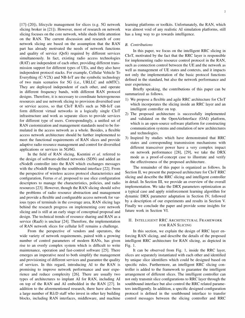
function. The type definition is generated after the ASN.1data structure initialization, and contains all the data typesdescribed in ASN.1. The ASN.1 data structure initializationscheme for RRC slices involved in this paper is shown inFig. 3. Based on different RRC slices, the message processingmodule generates data structure files corresponding to the RRCmessages of the current slice RAT during the initializationphase, right after that the command of adding a new sliceis received. After the slice initialization is completed, the datastructure prototype in the relevant source files can be accessedthrough the identifier slice id to implement the function ofgenerating and processing the RRC message content. Thecodec function can realize the conversion between this datatype and the encoded data stream, i.e., encoding and decodingprocess. In addition to the ASN.1 compiler mentioned above,the codec function also involves a general runtime library thatcontains the basic rules for encoding and decoding ASN.1primitives.
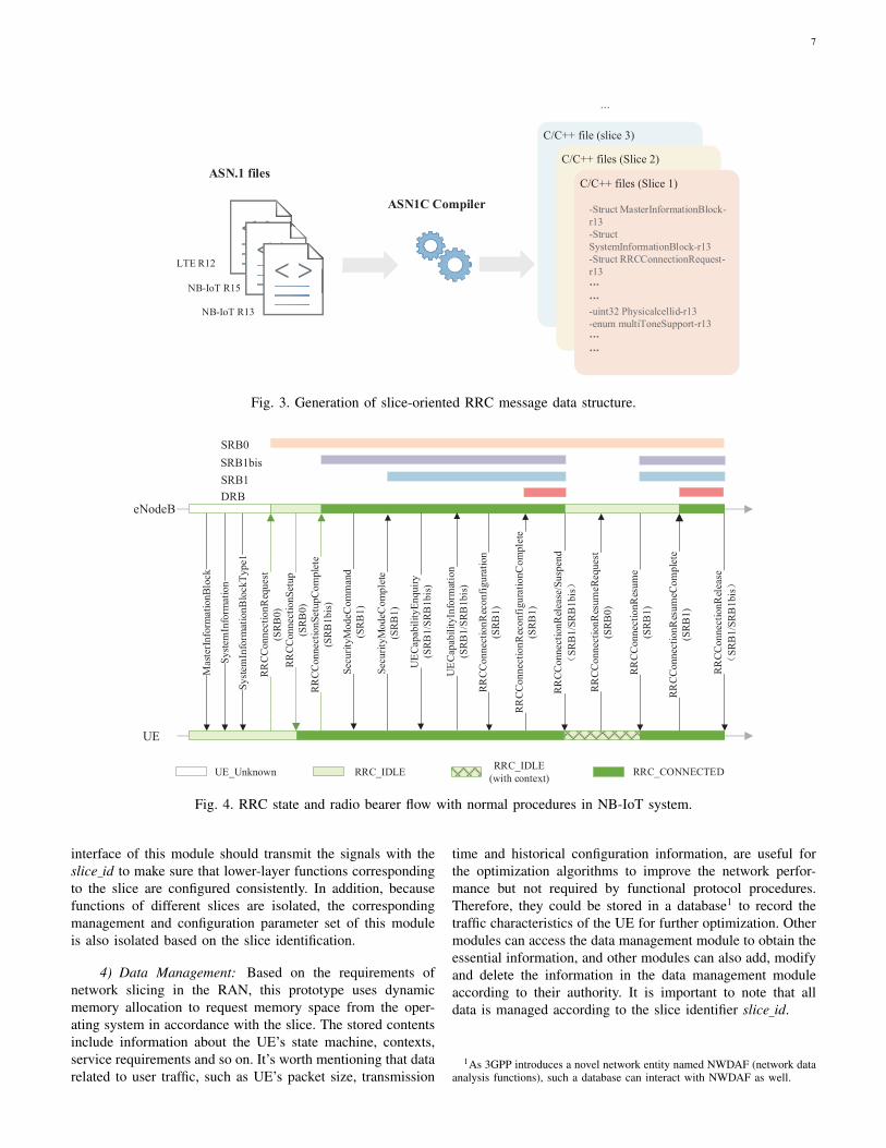
2) Collaboration Management: The collaboration man-agement module is very important in managing differenttasks. On one hand, this module includes the thread poolmanagement of all the main functions in the RRC layer,manages the communication between threads, and controlsdifferent slices according to the command received from RRCslicing interface. On the other hand, it is also responsiblefor the scheduling, execution and management of variousRRC functions and other modules, and cooperatively managesthe implementation of various contexts, procedures and statemachine. As the execution of RRC procedures, the connectionstate machine and related bearers changes accordingly with
the management of the module. An example of NB-IoT stateand radio bearer flow under normal RRC procedures is shownin Fig. 4. Procedure management is the main function of theRRC layer in CIoT and is implemented by the collaborativemanagement module. Besides managing the RRC messagetransmission between the BS and the UEs, it is also responsiblefor the management of RRC status and contexts. RRC mes-sages scheduled by the module are roughly divided into threecategories: system information, paging and connection controlmessages. The system information broadcasting and pagingprocedures are initiated by the BS while UE is responsible forreceiving and processing the indication information containedin the message. The connection control includes both uplinkand downlink signalings.
3) Control Interface: Through the definition of the inter-layer interface and the transfer of configuration parameters,communication between layers can be realized and RRC layercan achieve the purpose of controlling the functions of lowerlayers. From 3GPP TS 36.331, we can know that most ofthese inter-layer parameters involved the management andconfiguration of each layer are defined in RadioResource-ConfigDedicated IE which belongs to several specific RRCsignallings. The particular content of this IE can be seen inFig. 5. It contains many parameters related to power control,transmission reliability, and connection resource allocation,such as DRXCycle in MAC layer and DiscardTimer in PDCPlayer, which represents the discontinous reception cycle andthe maximum time to wait before discarding a PDCP packetrespectively. As slice division is independent of each other indifferent protocol layers under the proposed framework, the
7
ASN1C Compiler
C/C++ file (slice 3)
-service type-RAT type-priority-function set-rrc capacity set-rrc msg list-rrm policy-rrc requirements
C/C++ files (Slice 2)
-service type-RAT type-priority-function set-rrc capacity set-rrc msg list-rrm policy-rrc requirements
C/C++ files (Slice 1)
-Struct MasterInformationBlock-r13-StructSystemInformationBlock-r13-Struct RRCConnectionRequest-r13
-uint32 Physicalcellid-r13-enum multiToneSupport-r13
...
NB-IoT R15
LTE R12
NB-IoT R13
ASN.1 files
Fig. 3. Generation of slice-oriented RRC message data structure.
RRCC
onne
ctio
nReq
uest
(SRB
0)RR
CCon
nect
ionS
etup
(SRB
0)RR
CCon
nect
ionS
etup
Com
plet
e(S
RB1b
is)
Syste
mIn
form
atio
nBlo
ckTy
pe1
Syste
mIn
form
atio
n
Secu
rityM
odeC
ompl
ete
(SRB
1)
Secu
rityM
odeC
omm
and
(SRB
1)
RRCC
onne
ctio
nRec
onfig
urat
ion
(SRB
1)
RRCC
onne
ctio
nRec
onfig
urat
ionC
ompl
ete
(SRB
1)
RRCC
onne
ctio
nRel
ease
/Sus
pend
SRB
1/SR
B1b
is
RRCC
onne
ctio
nRes
umeR
eque
st(S
RB0)
RRCC
onne
ctio
nRes
umeC
ompl
ete
(SRB
1)
RRCC
onne
ctio
nRes
ume
(SRB
1)
RRCC
onne
ctio
nRel
ease
SRB
1/SR
B1b
is
Mas
terIn
form
atio
nBlo
ck
eNodeB
UE
SRB0SRB1bisSRB1
RRC_CONNECTEDRRC_IDLE RRC_IDLE(with context)UE_Unknown
UEC
apab
ility
Enqu
iry(S
RB1/
SRB
1bis)
UEC
apab
ility
Info
rmat
ion
(SRB
1/SR
B1b
is)
DRB
Fig. 4. RRC state and radio bearer flow with normal procedures in NB-IoT system.
interface of this module should transmit the signals with theslice id to make sure that lower-layer functions correspondingto the slice are configured consistently. In addition, becausefunctions of different slices are isolated, the correspondingmanagement and configuration parameter set of this moduleis also isolated based on the slice identification.
4) Data Management: Based on the requirements ofnetwork slicing in the RAN, this prototype uses dynamicmemory allocation to request memory space from the oper-ating system in accordance with the slice. The stored contentsinclude information about the UE’s state machine, contexts,service requirements and so on. It’s worth mentioning that datarelated to user traffic, such as UE’s packet size, transmission
time and historical configuration information, are useful forthe optimization algorithms to improve the network perfor-mance but not required by functional protocol procedures.Therefore, they could be stored in a database1 to record thetraffic characteristics of the UE for further optimization. Othermodules can access the data management module to obtain theessential information, and other modules can also add, modifyand delete the information in the data management moduleaccording to their authority. It is important to note that alldata is managed according to the slice identifier slice id.
1As 3GPP introduces a novel network entity named NWDAF (network dataanalysis functions), such a database can interact with NWDAF as well.

8
PDCP
RLC
MAC
PHY
SRB-ToAddModList
-RLC-Config
-LogicalChannelConfig
DRB-ToAddModList
-EPS-BearerIdentity
-DRB-Identity
DRB-ToReleaseList
-DRB-Identity
MAC-MainConfig
-UL-SCH-Config
-DRX-Config
PhysicalConfigDedicated
-CarrierConfigDedicated
-NPDCCH-ConfigDedicated
RLF-TimersAndConstants
-T301
-T310
-PDCP-Config
-RLC-Config
-LogicalChannelConfig
-LogicalChannelIdentity
-TimeAlignmentTimer
-logicalChannelSR-Config
-NPUSCH-ConfigDedicated
-N310
-T311
-N311
Fig. 5. Parameters in RadioResourceConfigDedicated IE re-lated with lower-layer configurations
5) RRC Slicing Interface: When the intelligentRRC/RAN slicing controller sends a command to the RRClayer through this interface, the RRC slicing interface parsesthe command and completes corresponding functions suchas slice establishment, configuration, maintenance, andmodification based on the command. The format of thecontrol command may be defined as a dedicated protocolwith specially-designed descriptors, which are used to definethe parameters, policies and functions of the slice. Once theslice defined by the intelligent RRC/RAN slicing controlleris established, other modules in this layer also executethe corresponding processes and functions correspondingto the RRC slice based on slice id, so as to achieve themutual isolation. From the perspective of RRC slicing, thesouthbound interface of the slicing controller is simplified inthe implementation, rather than based on a series of rigorousand unified control signals. Therefore, in our prototype,simply-defined control commands will be transmittedbetween the RRC slicing controller and RRC layer withcustomized functions and attribute descriptors to meet therequirements of managing multiple RRC slices logically. Inour solution, each specific RRC slice manifests itself as asingle thread running independently with each other.
6) Intelligent RRC Slicing Controller: The module isused as a smart manager to slices and can receive policiesfrom the northbound interface. However, in our prototype,we simplify the implementation of the northbound interfaceand only realize the controller as an entity which can sendcommands to the RRC layer. We also add primitives tocontrol RRC parameters and functions in this module toenable the flexible transplant of intelligent algorithms. Dueto the separation of RRC layer, the algorithms will not impactthe normal protocol flows except functions and parametersconfiguration. It is also slice-specific like other RRC modules.
Our prototype only incorporates the controller for RRC slicingand intelligent control, but it can be extended to other layerseasily.
IV. INTELLIGENT ALGORITHM FOR DRX IN CIOT SYSTEM
As depicted in Fig. 1, the RAN slicing controller isdesigned with APIs reserved for implanting algorithms whichcould intelligently control slices and accordingly influence theperformance of network and UEs. As mentioned before, RRClayer can affect many aspects of connections between the UEand the BS by adjusting functions and timers. Thus, it isessential for intelligent RAN slicing controller to control theslices with related algorithms. In this section, we take accountof the problem of energy efficiency and downlink transmissionlatency optimization under DRX mode as an example, so as toillustrate the effects of implementing reinforcement learning inRRC slicing controller and demonstrate how the reinforcementlearning algorithm can optimize the configuration of DRXparameters.
A. DRX Model
The DRX mode is an effective way to decrease the powercomsumption of the UEs in CIoT. This mode reduces theenergy consumed by enforcing the UE go to sleep periodically.As mentioned in Section III, the RadioResourceConfigDedi-cated IE is used to realize the configuration of parametersrelated to the connection, bearer and lower layer functionsno matter in the process of establishing, reconfiguring, or re-establishing RRC connections. DRX parameters are includedin this IE and transfered to UEs through RRC messages. Inother words, the RRC layer configures these DRX parametersand controls the DRX mode of the UEs.
When the BS manages the terminal under CIoT UPscheme, it needs to establish an RRC connection betweenUE and itself first before it can perform subsequent signalingprocesses and user data transmission. For UE accessing thenetwork for the first time, UE-specific RRC parameters needto be configured through the RRC connection reconfigurationprocedure. Subsequently, UE periodically enters the idle statebased on the DRX parameters from the configuration message.If the traffic mode of the UE changes, the RRC layer on theBS side should intelligently inform the UE with the dynami-cally adjusted DRX parameters through the RRC connectionreconfiguration signaling. The DRX parameter configurationalgorithm should be based on statistical data of user trafficrecorded by the storage module in the RRC layer. The intelli-gent RRC slicing controller, as the decision-making entity, cantake advantage of its historical traffic characteristics to performservice analysis and reconfigure parameters accordingly. Theconfiguration is transferred to the RRC layer through thesouthbound interface. During this process, the BS continuouslymonitors and updates the downlink service transmission statusof the UE as input information for the algorithm. Then, theslicing control makes decision in time with the execution of theservice and enforces RRC layer to adjust the DRX parametersof the UE to fit in the traffic mode.
9
!"# $ 10 +!%"
# &%'(# = 0
UE DRX state
!" !" !"
! ! ! ! !
!" !" !" Downlink
packet arrival
redetermine DRX parameters
! = 6
!" !"# !"
!"#
!" # 10 +!$"%%&' = 0
1 Inactivity timer is running 0 UE receives downlink data
2 Active state under DRX mode 3 Idle state under DRX mode
Fig. 6. UE state transition under DRX mechanism
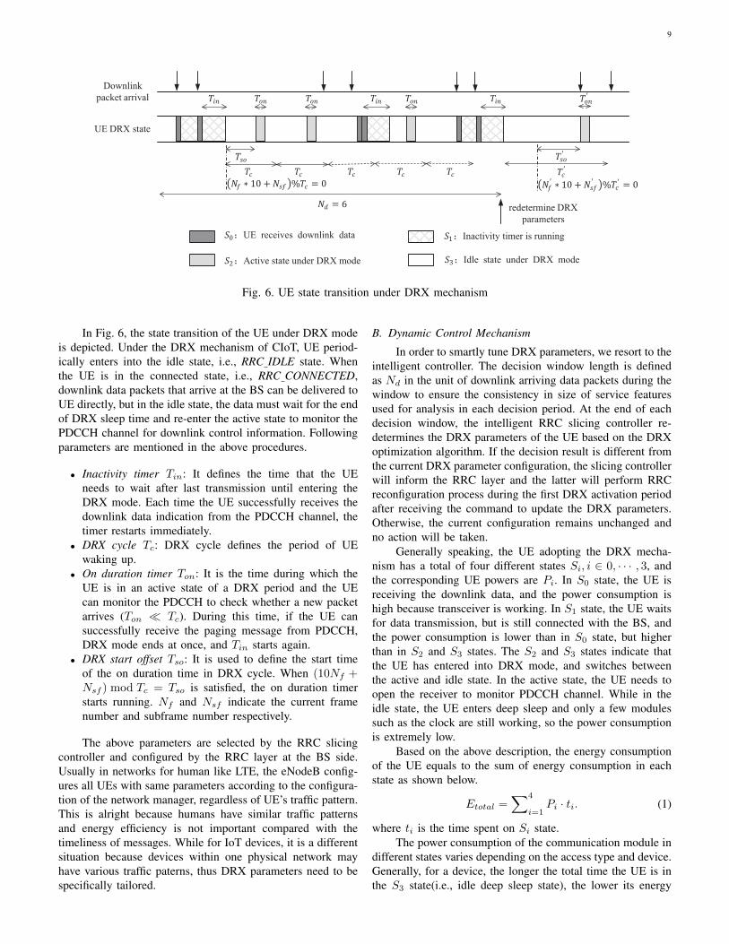
In Fig. 6, the state transition of the UE under DRX modeis depicted. Under the DRX mechanism of CIoT, UE period-ically enters into the idle state, i.e., RRC IDLE state. Whenthe UE is in the connected state, i.e., RRC CONNECTED,downlink data packets that arrive at the BS can be delivered toUE directly, but in the idle state, the data must wait for the endof DRX sleep time and re-enter the active state to monitor thePDCCH channel for downlink control information. Followingparameters are mentioned in the above procedures.
• Inactivity timer Tin: It defines the time that the UEneeds to wait after last transmission until entering theDRX mode. Each time the UE successfully receives thedownlink data indication from the PDCCH channel, thetimer restarts immediately.
• DRX cycle Tc: DRX cycle defines the period of UEwaking up.
• On duration timer Ton: It is the time during which theUE is in an active state of a DRX period and the UEcan monitor the PDCCH to check whether a new packetarrives (Ton � Tc). During this time, if the UE cansuccessfully receive the paging message from PDCCH,DRX mode ends at once, and Tin starts again.
• DRX start offset Tso: It is used to define the start timeof the on duration time in DRX cycle. When (10Nf +Nsf ) mod Tc = Tso is satisfied, the on duration timerstarts running. Nf and Nsf indicate the current framenumber and subframe number respectively.
The above parameters are selected by the RRC slicingcontroller and configured by the RRC layer at the BS side.Usually in networks for human like LTE, the eNodeB config-ures all UEs with same parameters according to the configura-tion of the network manager, regardless of UE’s traffic pattern.This is alright because humans have similar traffic patternsand energy efficiency is not important compared with thetimeliness of messages. While for IoT devices, it is a differentsituation because devices within one physical network mayhave various traffic paterns, thus DRX parameters need to bespecifically tailored.
B. Dynamic Control Mechanism
In order to smartly tune DRX parameters, we resort to theintelligent controller. The decision window length is definedas Nd in the unit of downlink arriving data packets during thewindow to ensure the consistency in size of service featuresused for analysis in each decision period. At the end of eachdecision window, the intelligent RRC slicing controller re-determines the DRX parameters of the UE based on the DRXoptimization algorithm. If the decision result is different fromthe current DRX parameter configuration, the slicing controllerwill inform the RRC layer and the latter will perform RRCreconfiguration process during the first DRX activation periodafter receiving the command to update the DRX parameters.Otherwise, the current configuration remains unchanged andno action will be taken.
Generally speaking, the UE adopting the DRX mecha-nism has a total of four different states Si, i ∈ 0, · · · , 3, andthe corresponding UE powers are Pi. In S0 state, the UE isreceiving the downlink data, and the power consumption ishigh because transceiver is working. In S1 state, the UE waitsfor data transmission, but is still connected with the BS, andthe power consumption is lower than in S0 state, but higherthan in S2 and S3 states. The S2 and S3 states indicate thatthe UE has entered into DRX mode, and switches betweenthe active and idle state. In the active state, the UE needs toopen the receiver to monitor PDCCH channel. While in theidle state, the UE enters deep sleep and only a few modulessuch as the clock are still working, so the power consumptionis extremely low.
Based on the above description, the energy consumptionof the UE equals to the sum of energy consumption in eachstate as shown below.
Etotal =∑4
i=1Pi · ti. (1)
where ti is the time spent on Si state.The power consumption of the communication module in
different states varies depending on the access type and device.Generally, for a device, the longer the total time the UE is inthe S3 state(i.e., idle deep sleep state), the lower its energy

10
consumption is. Considering the generality of the algorithmapplied to different types of CIoT devices, and the lack ofreliable measured power data of UE devices, the UE’s energyefficiency measurement indicator is simplified as the ratio oftime taken by the UE in the DRX sleep state to the total timeof the decision interval:
α =Toffset +Nc(Tc − Ton)
Td, (2)
where Td is the time interval for making DRX decisions, whichis related to the arrival of the downlink data; Toffset indicatesthe length of the first DRX sleep phase in the decision interval;Nc is the number of DRX cycles in the interval.
The average transmission delay of UE data packets isgiven as:
β =
∑Nd
j=1 ∆tj
Nd, (3)
where the transmission delay of the j-th downlink data packet∆tj is the time difference between the arrival and actualtransmission of the data packet, i.e. ∆tj = tjtx − tjarrive.Compared to the DRX cycle, the transmission processing timeis very short and can be ignored, so we assume that when theUE is in the S0, S1, S2 state, the downlink transmission delayequels zero.
According to the specification, the DRX parameters areall discrete values. There is a trade-off relationship betweenenergy efficiency and downlink transmission delay. If the DRXcycle is small and the UE frequently listens to the channel,the downlink data transmission delay is small but the averagepower of the UE is high. In contrast, if the DRX cycle islong, the UE is dormant for a long time and the averagepower is low, but the downlink data transmission delay willincrease. Meanwhile, in the actual IoT application scenarios,different types of services have different requirements forlatency and power consumption. For example, low-frequencydata collection services such as water metering have low la-tency requirements but strict power consumption requirements,and instant services such as traffic guidance signals are time-sensitive due to the timeliness of information. Therefore, wedefines an energy efficiency and delay (ED) indicator forevaluating the energy efficiency and delay of different CIoTUEs. This indicator is defined as:
fED(λ, Tmax) = λα+ (1− λ)(1− β
Tmax), (4)
where λ ∈ [0, 1] is a parameter used to define the relative im-portance between power consumption and delay in ED index.Tmax represents the maximum average delay that the UE cantolerate. When the average delay of the UE exceeds Tmax, thedelay part of the ED index has a negative impact on the overallvalue. The objective is to find a suitable DRX parameterconfiguration DRXp for the UE to maximize the ED indexwhile meeting the transmission delay requirements at the sametime. DRXp is the configuration set of (Tc, Ton, Tin, Tso).Thus, it can be summarized as:
DRXp = arg maxDRXp
fED(λ, Tmax). (5)
C. DRX Optimization Algorithm based on Q-learning
The arrival times of all downlink data packets are observ-able by the BS, and the state of the UE upon arrival is indeedaffected by DRX parameters. In other words, different DRXparameters (Tc, Ton, Tin, Tso) may result in different states ofthe UE even if downlink services arrive at the same time, andtherefore affect the power consumption and delay of the UE. Inthis way, the selection of certain DRX parameters will generatesome rewards by reducing the power consumption, and alsoaffect the state of the UE when the downlink data arrives.The reward and environmental state changes are feedbackand used by the intelligent controller to make the decisionat the end of the period, which is passed to the collaborativemanagement module for connection reconfiguration when theDRX parameter set changes. This process can be modeled asa Markov decision process (MDP) and can be solved by usingalgorithms based on reinforcement learning.
As the model involves discrete state and discrete actionspace, so the MDP can be defined as M =< S,A, T,R >,where S, A, T and R are the set of states, actions, transitionprobabilities, and reward respectively. To be specific, the RRClayer executes the action of RRC reconfiguration a ∈ Aafter the intelligent controller makes the decision and passesDRX parameters through the interface. Then the state willchange from s ∈ S during the last window to s′ ∈ S ofthe next window. The controller will also receive a real-timereward R(s, a) to evaluate the chosen action. When eachdata packet arrives, the UE must be in one of four statesSi, i ∈ {0, 1, 2, 3}, which is defined as sni , n is the sequencenumber of the downlink packet in the decision window. Soin our solution, the state s is indeed a series of downlinkpackets’ arrival states, so we define the environment stateduring kth decision window as sk = {s1i , s2i , ..., s
Ndi }k ∈ S ,
where i ∈ {0, 1, 2, 3}. Based on the environmental state, theintelligent controller makes action decisions to reconfigure theparameter set DRXp. According to the TS 36.331 document[30], the action space is like follows.
Tc = 256ncTsf ,
nc ∈ {1, 2, 4, 6, 8, 12, 16, 18, 24, 30, 32, 36},(6)
where nc denotes the number of groups containing 256 sub-frames in a period, Tsf denotes the time of a subframe, usually1ms in CIoT.
Ton=nonTpp, non ∈ {1, 2, 3, 4, 8, 16, 32}, (7)
where non is the numbers of PDCCH periods in on durationtimer, Tpp represents the length of an PDCCH period. In orderto simplify the calculation, this paper regards a PDCCH periodas 16ms.
Tin = ninTpp, nin ∈ {0, 1, 2, 3, 4, 8, 16, 32}, (8)
where nin is the numbers of PDCCH periods of inactivitytimer.
Tso =nso256
Tc, nso ∈ {0, 1, ..., 255}, (9)
where nso is the number of subframes by step of Tc
256 .The Q-learning algorithm [35] in reinforcement learning
can be used to dynamically configure these parameters to meet

11
the UE’s requirements on latency and power consumption asshown in Algorithm 1.
Algorithm 1 DRX parameters configuration based on Q-learning
Input: Initialize the Q value table, discount factor γ, learningrate α and DRX parameters DRXp(Tc, Ton, Tin, Tso).
Output: A series of DRX parameters.1: repeat2: Calculate the reward r and state s′ of the last decision
cycle (tn−Nd∼ tn).
3: if in exploit mode then4: Perform feedback value fading detection.5: if R(s, a)− r < rth then6: switch to explore mode7: else8: keep the current parameter configuration un-
changed.9: end if
10: else if in explore mode then11: update Q-table: Q(s, a) ← Q(s, a) + α[r +
γmaxaQ(s′, a)−Q(s, a)];12: update the current status: s← s′;13: use ε − greedy strategy to select the action a
to get the corresponding Tc, Ton, and T k+1so =
1Nd
i=kNd∑i=(k−1)Nd+1
((fi + sfi) mod T k+1c )/T k+1
c , we
get the new parameters DRX ′p(Tc, Ton, Tin, Tso);14: if DRX ′p(Tc, Ton, Tin, Tso) 6=
DRXp(Tc, Ton, Tin, Tso) then15: the BS performs the RRC connection reconfig-
uration procedure in the next activation state toreconfigures DRX parameters.
16: end if17: end if18: until UE detaches the current cell.
The algorithm mentioned can be regarded as the dynamiccontrol problem of DRX parameters. As the four parameters(Tc, Ton, Tin, Tso) work together, and they have an impacton the ED index of the UE. In order to reduce dimensionsof action space and accelerate the rapid convergence of thealgorithm in practical application scenarios, the algorithm isprocessed as follows:1) According to the discrete characteristics of DRX param-
eters, these parameters are encoded and mapped to thecorresponding action space except the start offset Tso. Tsois not a typical discrete variable, and it can be changed inreal time, so we simply update it based on the new DRXcycle and the data arrival time in last decision period.
2) We define a measurement criterion that can reflect theenergy efficiency and downlink transmission delay of theIoT devices. The algorithm learns continuously based onthe goal of maximizing this index.
3) In CIoT network, there are often changes in data patternscaused by human or special environmental changes. There-fore, for cases where the reward has dynamic changes, afeedback value fading detection is added to the algorithm
to determine the attenuation of real-time feedback underthe same state and action. If a certain degree of declineis detected, it indicates that the UE’s traffic model hassignificantly changed. As a result, the predicted rewardvalue needs to be updated, and exploration mode restartsto learn and adapt to the new traffic pattern.
V. EXPERIMENTS AND RESULTS
Due to the lack of integrated protocol stacks for oursolution, we use oaisim [36] to test the procedures and impactsof RRC slicing. oaisim is an emulator in OAI and can be usedto establish simulated interactions between the UE and the BSwhile compliant with communication protocols. We verify thecontent of protocol messages and the correctness of proceduresunder the OAI simulation environment, and the performance ofthe implemented RRC slicing is also presented. Moreover, thedynamic algorithm to configure DRX parameters mentionedabove is also evaluated.
A. RRC slicing
In the solution proposed, RRC slicing is implemented inthe OAI software, and the RRC layer can be informed byintelligent RRC slicing controller to create, modify and deleteslices. For this purpose, the main process of the RRC layeris implemented as a single process with multi-threads. Theprogram parses a configuration file and executes correspondingfunctions. It supports the initialization, modification and dele-tion of RRC slices through configuration files. After the mainthread for colaborative management is initialized, other threadscan be created to perform tasks such as the BS configurationand different RRC slice threads.
In our experiment, three IoT scenarios for water metering,bicycle-sharing communication, and video data transmissionare chosen to verify the functions of RRC slicing. Threetypes of RRC slices that meet the requirements of the abovescenarios are correspondingly instantiated, namely the NB-IoT with the CIoT CP optimization, and NB-IoT with theCIoT UP optimization and LTE. On one hand, time costto establish uplink transmission under different number ofslices are measured. On the other hand, the impact of adding,modifying or deleting slice on other slices is also validated.
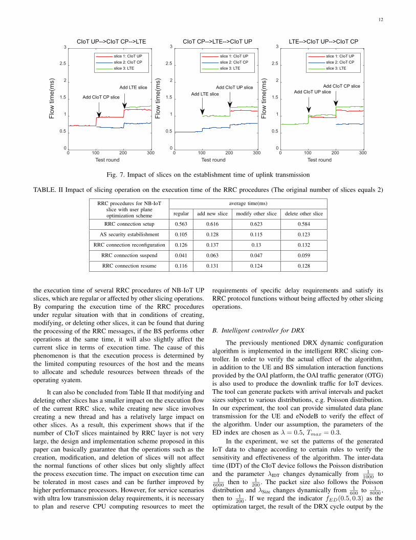
As the number of network slices increases, the processingtime required to establish an RRC uplink transmission isshown in Fig. 7. Notably, these experiments run on a 4-core CPU with a main frequency of 3.6GHz. The NB-IoTCP optimization solution can piggyback user data through theNAS message, so the processing time consumed is lower thanthe other two slices. It can also be seen from the figure that nomatter which type of slice, as the number of RRC layer slicesincreases, the time it takes for a single slice to execute theprotocol processing flow will increase slightly. When RRClayer supports 3 network slices, a normal 4-core CPU canguarantee that the processing delay of a one-way flow of eachRRC slice does not exceed 200us.
Furthermore, for RRC slices, it is also necessary to meetthe needs to minimize the impact on other existing sliceswhen creating, deleting and modifying slice. Table II records
12
0 100 200 300
Test round
0
0.5
1
1.5
2
2.5
3F
low
tim
e(m
s)
CIoT UP-->CIoT CP-->LTE
slice 1: CIoT UP
slice 2: CIoT CP
slice 3: LTE
0 100 200 300
Test round
0
0.5
1
1.5
2
2.5
3
Flo
w tim
e(m
s)
CIoT CP-->LTE-->CIoT UP
slice 1: CIoT UP
slice 2: CIoT CP
slice 3: LTE
0 100 200 300
Test round
0
0.5
1
1.5
2
2.5
3
Flo
w tim
e(m
s)
LTE-->CIoT UP-->CIoT CP
slice 1: CIoT UP
slice 2: CIoT CP
slice 3: LTE
Add CIoT CP slice
Add LTE slice
Add LTE slice
Add CIoT UP sliceAdd CIoT UP slice
Add CIoT CP slice
Fig. 7. Impact of slices on the establishment time of uplink transmission
TABLE. II Impact of slicing operation on the execution time of the RRC procedures (The original number of slices equals 2)
RRC procedures for NB-IoTslice with user planeoptimization scheme
average time(ms)
regular add new slice modify other slice delete other slice
RRC connection setup 0.563 0.616 0.623 0.584
AS security estabilishment 0.105 0.128 0.115 0.123
RRC connection reconfiguration 0.126 0.137 0.13 0.132
RRC connection suspend 0.041 0.063 0.047 0.059
RRC connection resume 0.116 0.131 0.124 0.128
the execution time of several RRC procedures of NB-IoT UPslices, which are regular or affected by other slicing operations.By comparing the execution time of the RRC proceduresunder regular situation with that in conditions of creating,modifying, or deleting other slices, it can be found that duringthe processing of the RRC messages, if the BS performs otheroperations at the same time, it will also slightly affect thecurrent slice in terms of execution time. The cause of thisphenomenon is that the execution process is determined bythe limited computing resources of the host and the meansto allocate and schedule resources between threads of theoperating syatem.
It can also be concluded from Table II that modifying anddeleting other slices has a smaller impact on the execution flowof the current RRC slice, while creating new slice involvescreating a new thread and has a relatively large impact onother slices. As a result, this experiment shows that if thenumber of CIoT slices maintained by RRC layer is not verylarge, the design and implementation scheme proposed in thispaper can basically guarantee that the operations such as thecreation, modification, and deletion of slices will not affectthe normal functions of other slices but only slightly affectthe process execution time. The impact on execution time canbe tolerated in most cases and can be further improved byhigher performance processors. However, for service scenarioswith ultra low transmission delay requirements, it is necessaryto plan and reserve CPU computing resources to meet the
requirements of specific delay requirements and satisfy itsRRC protocol functions without being affected by other slicingoperations.
B. Intelligent controller for DRX
The previously mentioned DRX dynamic configurationalgorithm is implemented in the intelligent RRC slicing con-troller. In order to verify the actual effect of the algorithm,in addition to the UE and BS simulation interaction functionsprovided by the OAI platform, the OAI traffic generator (OTG)is also used to produce the downlink traffic for IoT devices.The tool can generate packets with arrival intervals and packetsizes subject to various distributions, e.g. Poisson distribution.In our experiment, the tool can provide simulated data planetransmission for the UE and eNodeB to verify the effect ofthe algorithm. Under our assumption, the parameters of theED index are chosen as λ = 0.5, Tmax = 0.3.
In the experiment, we set the patterns of the generatedIoT data to change according to certain rules to verify thesensitivity and effectiveness of the algorithm. The inter-datatime (IDT) of the CIoT device follows the Poisson distributionand the parameter λIDT changes dynamically from 1
1000 to1
6000 then to 1200 . The packet size also follows the Poisson
distribution and λSize changes dynamically from 1600 to 1
8000 ,then to 1
200 . If we regard the indicator fED(0.5, 0.3) as theoptimization target, the result of the DRX cycle output by the

13
0 100 200 300 400 500 600
Episode
256512
1024
1536
2048
3072
4096
4608
6144
7680
8192
9216
DR
X c
ycle
(su
bfr
am
e)
lambda=1/1000 lambda=1/6000 lambda=1/200
Fig. 8. Dynamic parameter control for DRX cycle (IDTsubjects to Poisson distribution)
0 100 200 300 400 500 600
Episode
1234
8
16
32
On
Du
ratio
n T
ime
r(P
DC
CH
Pe
rio
d)
lambda=1/600 lambda=1/8000 lambda=1/200
Fig. 9. Dynamic parameter control for on duration timer (IDTsubjects to Poisson distribution)
dynamic configuration algorithm is shown in Fig. 8, and theresults of the DRX on duration timer is shown in Fig. 9.
From the results, we can see that the BS is able to adjustthe DRX cycle according to the traffic pattern. As the IDT inthe UE’s traffic model changes, the controller can detect themismatch of the current DRX cycle from the feedback result,then it re-learns a new DRX cycle. After several rounds oflearning (usually no more than 100 iterations) of the decisioncycle, the algorithm converges to a new value. Thus theRRC layer of the BS maintains the parameter configurationconsistent with the current traffic model. In other words, theoptimal configuration is maintained under the stable trafficmodel. Similarly, the BS can also detect the UE’s current DRXon duration timer mismatch in time and re-learn a new valuefor DRX on duration timer.
At the same time, the ED index of the UE is shown inFig. 10. It can be seen that the proposed algorithm based on Q-learning can effectively learn the appropriate DRX parametersto ensure that the ED index value of the UE stay at highlevel for a long time. Each time the traffic model changes,the process of learning again will make the ED index valuefluctuate for a while to explore the suitable parameters.
VI. CONCLUSIONS AND FUTURE CHALLENGES
This paper has presented a CIoT RRC framework toenable the RRC slicing and intelligent control, which is imple-mented and evaluated in the OAI platform. More specifically,
0 100 200 300 400 500 600
Episode
0
0.2
0.4
0.6
0.8
1
1.2
f ED(0.5,0.3)
Fig. 10. Dynamic optimization process for fED(0.5, 0.3) (IDTsubjects to Poisson distribution)
we have presented the implementation methodologies andvalidated the basic functions of RRC slicing as a proof-of-concept. We have also incorporated an intelligent controllerto manage the slices smartly in accordance with the servicerequirements. The Q-learning based algorithm for DRX pa-rameters configuration is selected as a typical case to manifestthe effect of the proposed intelligent RRC slicing architecture.Experiments have shown that the proposed architecture cannot only manage differently slices correctly but also customizeradio resource control intelligently and dynamically to adaptto the service changes.
We boldly argue that RAN slicing is highly important inthe future network and it will change the traditional networkarchitecture that has lasted for decades. Further investigationneeds to be conducted in related areas. This calls for notonly the evolution in network theory but also efforts fromengineering supporters. Moreover, as AI has already beenon its way towards maturation, related applications in CIoTsystems are an irreversible trend especially in areas of radioresource management and diversified services. In our futurework, we will further refine the proposed architecture tobetter match the practical network configurations and servicerequirements, and introduce other intelligent algorithms intothe system. Similar intelligent algorithms can also be appliedin other fields of radio resource control and management.For example, the retransmission times of the physical layerchannel in CIoT can be similarly configured based on real-time feedback from the UE, to ensure that UE can adaptivelyadjust retransmission times according to the channel qualityand it’s coverage condition. These aspects will be investigatedunder the framework in the near future.
REFERENCES
[1] 3GPP, “Cellular System Support for Ultra-Low Complexity and LowThroughput Internet of Things (CIoT),” 3rd Generation PartnershipProject (3GPP), Technical Report (TR) 45.820, 11 2015, version 13.1.0.[Online]. Available: https://portal.3gpp.org/desktopmodules/Specifications/SpecificationDetails.aspx?specificationId=2719
[2] M. El Soussi, P. Zand, F. Pasveer, and G. Dolmans, “Evaluating thePerformance of eMTC and NB-IoT for Smart City Applications,” in2018 IEEE International Conference on Communications (ICC). IEEE,2018, pp. 1–7.

14
[3] 3GPP, “Feasibility Study on New Services and Markets TechnologyEnablers - Network Operation; Stage 1,” 3rd Generation PartnershipProject (3GPP), Technical Report (TR) 22.864, 9 2016, version 15.0.0.[Online]. Available: https://portal.3gpp.org/desktopmodules/Specifications/SpecificationDetails.aspx?specificationId=3016
[4] H. Karl and A. Willig, Protocols and Architectures for Wireless SensorNetworks. John Wiley & Sons, 2007.
[5] C. Y. Yeoh, A. bin Man, Q. M. Ashraf, and A. K. Samingan, “Exper-imental Assessment of Battery Lifetime for Commercial off-the-shelfNB-IoT Module,” in 2018 20th International Conference on AdvancedCommunication Technology (ICACT). IEEE, 2018, pp. 223–228.
[6] S.-M. Oh, K.-R. Jung, M. Bae, and J. Shin, “Performance Analysis forthe Battery Consumption of the 3GPP NB-IoT Device,” in 2017 In-ternational Conference on Information and Communication TechnologyConvergence (ICTC). IEEE, 2017, pp. 981–983.
[7] B. Martinez, F. Adelantado, A. Bartoli, and X. Vilajosana, “Exploringthe Performance Boundaries of NB-IoT,” IEEE Internet of ThingsJournal, vol. 6, no. 3, pp. 5702–5712, 2019.
[8] P. Jorke, R. Falkenberg, and C. Wietfeld, “Power Consumption Analysisof NB-IoT and eMTC in Challenging Smart City Environments,” in 2018IEEE Globecom Workshops (GC Wkshps). IEEE, 2018, pp. 1–6.
[9] S.-M. Oh and J. Shin, “An Efficient Small Data Transmission Schemein the 3GPP NB-IoT System,” IEEE Communications Letters, vol. 21,no. 3, pp. 660–663, 2016.
[10] B.-Z. Hsieh, Y.-H. Chao, R.-G. Cheng, and N. Nikaein, “Design of a UE-specific Uplink Scheduler for Narrowband Internet-of-Things (NB-IoT)Systems,” in 2018 3rd International Conference on Intelligent GreenBuilding and Smart Grid (IGBSG). IEEE, 2018, pp. 1–5.
[11] W. Ejaz, M. Naeem, A. Shahid, A. Anpalagan, and M. Jo, “EfficientEnergy Management for the Internet of Things in Smart Cities,” IEEECommunications Magazine, vol. 55, no. 1, pp. 84–91, 2017.
[12] 3GPP, “Feasibility Study on New Services and Markets TechnologyEna-blers for Critical Communications; Stage 1,” 3rd GenerationPartnership Project (3GPP), Technical Report (TR) 22.862, 10 2016,version 14.1.0. [Online]. Available: https://portal.3gpp.org/desktopmodules/Specifications/SpecificationDetails.aspx?specificationId=3014
[13] J. Frahim, C. Pignataro, J. Apcar, and M. Morrow, “Securing the Internetof Things: A Proposed Framework,” Cisco White Paper, 2015.
[14] 3GPP, “Service Requirements for the 5G System; Stage 1,” 3rdGeneration Partnership Project (3GPP), Technical Specification(TS) 22.261, 10 2019, version 17.0.1. [Online]. Available:
https://portal.3gpp.org/desktopmodules/Specifications/SpecificationDetails.aspx?specificationId=3107
[15] ——, “System Architecture for the 5G System; Stage 2,” 3rd GenerationPartnership Project (3GPP), Technical Specification (TS) 23.501, 3 2018,version 15.1.0. [Online]. Available: https://portal.3gpp.org/desktopmodules/Specifications/SpecificationDetails.aspx?specificationId=3144
[16] ——, “Study on Management and Orchestration of Network Slicing forNext Generation Network,” 3rd Generation Partnership Project (3GPP),Technical Specification (TS) 28.801, 3 2018, version 15.1.0. [Online].Available: https://portal.3gpp.org/desktopmodules/Specifications/SpecificationDetails.aspx?specificationId=3091
[17] X. Costa-Perez, J. Swetina, T. Guo, R. Mahindra, and S. Rangarajan,“Radio Access Network Virtualization for Future Mobile Carrier Net-works,” IEEE Communications Magazine, vol. 51, no. 7, pp. 27–35,2013.
[18] Y. Hua, R. Li, Z. Zhao, X. Chen, and H. Zhang, “GAN-powered DeepDistributional Reinforcement Learning for Resource Management inNetwork Slicing,” IEEE Journal on Selected Areas in Communications,2019.
[19] C. Qi, Y. Hua, R. Li, Z. Zhao, and H. Zhang, “Deep Reinforce-ment Learning with Discrete Normalized Advantage Functions for Re-source Management in Network Slicing,” IEEE Communications Letters,vol. 23, no. 8, pp. 1337–1341, 2019.
[20] R. Li, Z. Zhao, Q. Sun, I. Chih-Lin, C. Yang, X. Chen, M. Zhao, andH. Zhang, “Deep Reinforcement Learning for Resource Management inNetwork Slicing,” IEEE Access, vol. 6, pp. 74 429–74 441, 2018.
[21] K. Samdanis, X. Costa-Perez, and V. Sciancalepore, “From NetworkSharing to Multi-Tenancy: The 5G Network Slice Broker,” IEEE Com-munications Magazine, vol. 54, no. 7, pp. 32–39, 2016.
[22] A. Ksentini and N. Nikaein, “Toward Enforcing Network Slicing onRAN: Flexibility and Resources Abstraction,” IEEE CommunicationsMagazine, vol. 55, no. 6, pp. 102–108, 2017.
[23] R. Ferrus, O. Sallent, J. Perez-Romero, and R. Agusti, “On 5G RadioAccess Network Slicing: Radio Interface Protocol Features and Config-uration,” IEEE Communications Magazine, vol. 56, no. 5, pp. 184–192,2018.
[24] X. Foukas, G. Patounas, A. Elmokashfi, and M. K. Marina, “NetworkSlicing in 5G: Survey and Challenges,” IEEE Communications Maga-zine, vol. 55, no. 5, pp. 94–100, 2017.
[25] D. C. Francesco, F. Philipp, G. Euhanna, C. Ursula, andS. Pablo, “Enhancing RAN Performance with AI,” Ericsson,Ericsson Technology Review, 1 2020. [Online]. Available:
https://www.ericsson.com/493ce3/assets/local/reports-papers/ericsson-technology-review/docs/2020/enhancing-ran-performance-with-ai.pdf
[26] R. Li, Z. Zhao, X. Zhou, G. Ding, Y. Chen, Z. Wang, and H. Zhang,“Intelligent 5G: When Cellular Networks Meet Artificial Intelligence,”IEEE Wireless Communications, vol. 24, no. 5, pp. 175–183, 2017.
[27] R. Agrawal, “Machine Learning for 5G RAN,” Algorithm Innovations,Mobile Networks ATF, Tech. Rep., 08 2018. [Online]. Available:
https://www.itu.int/en/ITU-T/Workshops-and-Seminars/20180807/Documents/Ran ML.pdf
[28] J. Huang, F. Qian, A. Gerber, Z. M. Mao, S. Sen, and O. Spatscheck,“A Close Examination of Performance and Power Characteristics of 4GLTE networks,” in Proceedings of the 10th International Conference onMobile Systems, Applications, and Services, 2012, pp. 225–238.
[29] S. Rosen, H. Luo, Q. A. Chen, Z. M. Mao, J. Hui, A. Drake, andK. Lau, “Discovering Fine-Grained RRC State Dynamics and Perfor-mance Impacts in Cellular Networks,” in Proceedings of the 20th AnnualInternational Conference on Mobile Computing and Networking, 2014,pp. 177–188.
[30] 3GPP, “Evolved Universal Terrestrial Radio Access (E-UTRA);Radio Resource Control (RRC); Protocol specification,” 3rdGeneration Partnership Project (3GPP), Technical Specification(TS) 36.331, 09 2018, version 15.3.0. [Online]. Available:
https://portal.3gpp.org/desktopmodules/Specifications/SpecificationDetails.aspx?specificationId=2440
[31] ——, “Study on New Radio Access Technology: Radio AccessArchitecture and Interfaces,” 3rd Generation Partnership Project(3GPP), Technical Report (TR) 38.801, 3 2017, version 14.0.0.[Online]. Available: https://portal.3gpp.org/desktopmodules/Specifications/SpecificationDetails.aspx?specificationId=3056
[32] The OpenAirInterface (OAI) Platform, Website, https://www.openairinterface.org/.
[33] N. Nikaein, R. Knopp, F. Kaltenberger, L. Gauthier, C. Bonnet, D. Nuss-baum, and R. Ghaddab, “OpenAirInterface: An Open LTE Network ina PC,” in Proceedings of the 20th annual international conference onMobile computing and networking, 2014, pp. 305–308.
[34] ASN.1 Compiler (ASN1C), Website, https://www.obj-sys.com/products/asn1c/.
[35] C. J. Watkins and P. Dayan, “Q-learning,” Machine learning, vol. 8, no.3-4, pp. 279–292, 1992.
[36] OpenAirInterface System Emulation, Website, https://gitlab.eurecom.fr/oai/openairinterface5g/wikis/OpenAirLTEEmulation/.