intellitouch pool and spa control system - poolplaza
TRANSCRIPT

IntelliTouch® Pool and SpaControl System
IMPORTANT SAFETY INSTRUCTIONSREAD AND FOLLOW ALL INSTRUCTIONSSAVE THESE INSTRUCTIONS
pool/spa control system
User’s Guide

© 2009 Pentair Water Pool and Spa, Inc. All rights reserved
This document is subject to change without notice
1620 Hawkins Ave., Sanford, NC 27330 • (919) 566-800010951 West Los Angeles Ave., Moorpark, CA 93021 • (805) 523-2400
Trademarks and disclaimers
IntelliTouch®, MagicStream®, ScreenLogic®, IntelliChlor®, IntelliFlo®, MobileTouch®, QuickTouch®, IntelliBrite®,SAm®, SAL®, FIBERworks®, Amerlite®, SpaBrite®, Photon Generator®, and Pentair Water Pool and Spa® aretrademarks and/or registered trademarks of Pentair Water Pool and Spa, Inc. Aqua Rite™ is a trademark of HaywardIndustries, Inc. AutoClear® is a registered trademark of Zodiac Pool Care. Crestron® is a registered trademark ofCrestron Electronics. Liton™ is trademark of Liton Lighting. LLC and Pool Pilot® is a registered trademark of AutopilotSystems Inc. Unless noted, names and brands of others that may be used in this document are not used to indicate anaffiliation or endorsement between the proprietors of these names and brands and Pentair Water Pool and Spa, Inc.Those names and brands may be the trademarks or registered trademarks of those parties or others.
P/N 520102 Rev H 02/04/09

i
IntelliTouch Pool and Spa Control System User’s Guide
ContentsImportant Safety Precautions ........................................................................................................................... vIn this User’s Guide ..............................................................................................................................................vi
Technical Support ..........................................................................................................................................viRelated IntelliTouch Manuals .........................................................................................................................vi
SECTION 1 - INTELLITOUCH SYSTEM OVERVIEW ....................................................................................... 1
Introduction .......................................................................................................................................................... 1IntelliTouch System Overview .............................................................................................................................. 1 In the home.................................................................................................................................................... 1 Around the pool ............................................................................................................................................. 1 At the equipment pad..................................................................................................................................... 1IntelliTouch System Components ......................................................................................................................... 2 Load or Power Center ................................................................................................................................... 2 IntelliTouch Personality Kits ........................................................................................................................... 2 IntelliTouch Interfaces .................................................................................................................................... 3 IntelliTouch in your home ............................................................................................................................... 4IntelliTouch Interface Kits ..................................................................................................................................... 5 PC Interface (iTC15 Kit - P/N 520500) .......................................................................................................... 5 Personal Digital Assistant (PDA) (iTC25 Kit - P/N 520501) .......................................................................... 5 In-Wall Touch Screen (iTC35 Kit - P/N 520502) ............................................................................................ 5 Digital Wireless Tablet (iTC45 Kit - P/N 520503) ........................................................................................... 5IntelliTouch ScreenLogic Interface Accessory Kits .............................................................................................. 5
SECTION 2 - OPERATING THE INTELLITOUCH SYSTEM ............................................................................. 7
Main Screen (Indoor Control Panel and MobileTouch wireless control panel) ...................................................... 7IntelliTouch Menus ................................................................................................................................................ 8 Indoor Control Panel Menus .......................................................................................................................... 9Heating your Spa and Pool ................................................................................................................................. 10 Adjust Spa or Pool Heat Settings ................................................................................................................ 10 Selecting the Heating System ..................................................................................................................... 11Switching on Lights Manually ............................................................................................................................. 12Special Lighting Features ................................................................................................................................... 13Dimming Lights ................................................................................................................................................... 14Setting ON/OFF Times for Equipment (PROGRAM) ......................................................................................... 14 Smart Start (Setting up SAm, SAL and IntelliBrite lights) ............................................................................ 15 Using the Once Only Timer ......................................................................................................................... 16 Setting the Egg Timer Function ................................................................................................................... 17iS10 Spa-Side Remote Controller ...................................................................................................................... 18iS4 Spa-Side Remote Controller ........................................................................................................................ 19MobileTouch Wireless Controller ........................................................................................................................ 19 Charging the MobileTouch Wireless Controller ............................................................................................ 20 Using the MobileTouch Wireless Controller ................................................................................................. 20QuickTouch Wireless QT4 Remote Controller ................................................................................................... 21IntelliChlor Salt Chlorine Generator (Accessory) ............................................................................................... 21IntelliFlo VF Variable Flow Pump Accessory ...................................................................................................... 22IntelliFlo VS (4x160) Variable Speed Pump (Accessory) ................................................................................... 22

IntelliTouch Pool and Spa Control System User’s Guide
ii
Contents (Continued)
SECTION 3 - PREPARING THE SYSTEM FOR INITIAL START-UP ............................................................. 23
Setting up the IntelliTouch System ..................................................................................................................... 23Automatically Enabled Wired Controllers ........................................................................................................... 25Adding Multiple iS10 Spa-Side remotes and Expansion Centers ....................................................................... 25Adding a MobileTouch Wireless Controller ......................................................................................................... 25 Manually Enabling Expansion Centers........................................................................................................ 26 Assigning Additional Expansion Centers .................................................................................................... 27Setting up the MobileTouch Wireless Controller ................................................................................................. 28Adding an iS10 Spa-Side Remote Controller ..................................................................................................... 30Prepare the System for Operation ..................................................................................................................... 31 Checking the Main Load Center .................................................................................................................. 31 Setting up the IntelliTouch System using the Indoor Control Panel or MobileTouch .................................... 33 The Preference Screen Options .................................................................................................................. 33 Set the System Clock ................................................................................................................................. 34 Assigning Circuit Names (for Display 1, 2, 3, and 4) .................................................................................. 34 Selecting DISPLAY Screen 1, 2, 3, or 4 ...................................................................................................... 35Assigning Circuit Names.................................................................................................................................... 35Selecting the Display Screens ........................................................................................................................... 36IntelliTouch Circuit Names.................................................................................................................................. 37Creating Custom Names for Auxiliary Circuits .................................................................................................. 38Assign Circuit Functions and Freeze Protection ................................................................................................ 39Freeze Protection ............................................................................................................................................... 39Assigning a function and freeze protection to a circuit ....................................................................................... 39Special Functions for Circuits ............................................................................................................................ 41Setting up Lighting Options (Color Swim and Color Set) .................................................................................... 42 Color Swim and Color Set ........................................................................................................................... 42 Setting up Color Swim and Color Set with SAm, SAL, or FIBERworks ...................................................... 42 Setting up Color Swim and Color Set lights ................................................................................................. 42Setting up IntelliBrite LED lights ......................................................................................................................... 46 Selecting IntelliBrite Modes ......................................................................................................................... 48 Modes screen ......................................................................................................................................... 48 Modes: Color light shows ........................................................................................................................ 48 Feature: Swim ............................................................................................................................................. 48 Feature: Color set ........................................................................................................................................ 49 Fixed Colors Screen ................................................................................................................................... 49 Fixed Colors: Hold/Recall Feature .............................................................................................................. 49Setting up MagicStream Laminars ..................................................................................................................... 50 Using the MagicStream Laminar Features ..................................................................................................... 52Setting up Equipment (from the Equipment Screen) .......................................................................................... 53Manual Priority Override of Timed Program Circuits .......................................................................................... 53Chlorine Generator ............................................................................................................................................. 54 Activating the Chlorinator ............................................................................................................................... 54 Adjusting the Chlorine Output Level ............................................................................................................... 54 Super Chlorinate the Pool Water ..................................................................................................................... 55IntelliFlo (model VF) and IntelliFlo 4x160 (VS) pump setup ................................................................................ 56 Setting up IntelliFlo ......................................................................................................................................... 56 How many pumps will IntelliTouch support? ................................................................................................. 56 Connecting power to an IntelliFlo pump......................................................................................................... 56 Assigning an IntelliFlo pump address ............................................................................................................. 56

iii
IntelliTouch Pool and Spa Control System User’s Guide
Contents (Continued)
IntelliFlo menu options .................................................................................................................................... 57 IntelliFlo main pump assignment screens ...................................................................................................... 57 IntelliFlo Set Parameters screens .................................................................................................................. 58 Assign or change a pump circuit name .......................................................................................................... 58 Filtering parameters........................................................................................................................................ 59 Priming parameters ........................................................................................................................................ 60 Backwash parameters ................................................................................................................................... 61 Vacuum parameters ....................................................................................................................................... 62 Assign custom flows ...................................................................................................................................... 63 IntelliFlo status screen ................................................................................................................................... 64IntelliFlo 4 (VS) pump setup ............................................................................................................................... 65 Setting up IntelliFlo 4 (VS) .............................................................................................................................. 65 Assigning an IntelliFlo 4 pump address .......................................................................................................... 65 Setting up an IntelliFlo 4 pump in the IntelliTouch menu ................................................................................. 66 Priming Parameters ........................................................................................................................................ 67 Assign custom speeds................................................................................................................................... 68 IntelliFlo 4 status screen ................................................................................................................................ 69Setting up a ThermalFlo Heat Pump................................................................................................................... 70 ThermalFlo screen ......................................................................................................................................... 70Setup Solar Equipment and Heat pump option ................................................................................................... 71 Setting up solar equipment ............................................................................................................................. 71 Setting up a heat pump and gas heater .......................................................................................................... 71Setting up a 2-Speed Pump ............................................................................................................................... 72Delay for Valves and Pumps (Heater Cool-Down Cycle) .................................................................................. 72Delay Cancel Feature ........................................................................................................................................ 73SPA Options Set Automatic Spa Heating When the Spa is Manually Switched On ............................................................ 74 Freeze Override 30-240 minutes .................................................................................................................... 74Changing the Display to Show Fahrenheit to Celsius ........................................................................................ 74Configuring Valve Actuators (Controlled by AUX or Feature Circuit) ................................................................. 75Feature Circuits .................................................................................................................................................. 76Assign a Circuit Name to a Feature Circuit ........................................................................................................ 76Creating a Macro Circuit .................................................................................................................................... 77Configuring Remote Control Button Circuits
(iS4, iS10, QT4 QuickTouch, and Phone Remote) ....................................................................................... 78Setting up the Remote Control Telephone Feature ............................................................................................. 79Disable/Enable iS10 and iS4 Spa-Side Remote ................................................................................................. 80Keypad Lock ...................................................................................................................................................... 80
SECTION 4 - SERVICE AND MAINTENANCE ............................................................................................... 81
Calibrating Temperature Sensors ....................................................................................................................... 81Using the Service Personnel Screen ................................................................................................................. 82Checking Firmware Version ............................................................................................................................... 82Manually Updating Between Indoor and Outdoor Control Panels ...................................................................... 83Erasing the System Memory .............................................................................................................................. 84System Worksheet Overview ............................................................................................................................ 85The Main Outdoor Control Panel ........................................................................................................................ 92Shared Equipment Systems i5+3, i7+3, i9+3 ..................................................................................................... 92Erasing Outdoor Control Panel Memory (Factory Default) ................................................................................. 94

IntelliTouch Pool and Spa Control System User’s Guide
iv
Contents (Continued)
SECTION 5 - TROUBLESHOOTING ............................................................................................................... 95
System Start-Up ................................................................................................................................................ 95 Check Electronics .......................................................................................................................................... 95 System Test .................................................................................................................................................... 95Troubleshooting .................................................................................................................................................. 96Frequently Asked Questions (FAQ) ................................................................................................................... 96 What does a ‘+3’ IntelliTouch system mean? .................................................................................................. 96 How Do I Setup/Configure/Program the 2-Speed Pump? .............................................................................. 96 Can I turn the Heater On and Change the temperature from the Spa? .......................................................... 96 How do I get Solar to switch on?.................................................................................................................... 96 What are Color Swim and Color Set? ............................................................................................................. 97 How do I get SAm/SAL/PG2000 to Synchronize? ......................................................................................... 97 Can I copy a standard configuration to all the systems I install? ................................................................... 97 Fixing mismatched system personalities ....................................................................................................... 98 Indoor Control Panel and Outdoor Control Panel Connection Problem .......................................................... 98 MobileTouch Temperature Readout Not Accurate (20 to 30 Degrees off) ...................................................... 98System Problem Diagnosis ................................................................................................................................ 99 Problem: The system works in Service Mode, but Indoor Control Panel fails to operate. .............................. 99 Problem: Indoor and Outdoor Control Panels work, but iS4 fails to operate. ............................................... 100 Problem: Indoor and Outdoor Control Panels work, but iS10 fails to operate. ............................................. 101 Problem: The Mobile Control Panel will not work, or will not work dependably. ........................................... 102 Problem: The Quick Touch remote will not work, or will not work dependably. ............................................ 103 Problem: The Quick Touch remote will not work, or will not work dependably (Continued). ........................ 104IntelliFlo Alerts and Warnings ........................................................................................................................... 105 Suction Blockage ......................................................................................................................................... 105IntelliFlo 4x160 Warning and Alarm Conditions ................................................................................................ 106 Alarm and warning LED sequence ............................................................................................................... 106Wiring IntelliTouch to a Salt Chlorine Generator ............................................................................................... 109Wiring ThermalFlo to IntelliTouch ...................................................................................................................... 109
Glossary .......................................................................................................................................................... 110

v
IntelliTouch Pool and Spa Control System User’s Guide
Important Notice:
Attention Installer: This manual contains important information about the installation, operation andsafe use of this product. This information should be given to the owner and/or operator of thisequipment.
WARNING - Before installing this product, read and follow all warning notices and instructionswhich are included. Failure to follow safety warnings and instructions can result in severe injury, death,or property damage. Call (800) 831-7133 for additional free copies of these instructions.
WARNING - Water temperature in excess of 100 degrees Fahrenheit may be hazardous to yourhealth. Prolonged immersion in hot water may induce hyperthermia. Hyperthermia occurs when theinternal temperature of the body reaches a level several degrees above normal body temperature of98.6° F (37° C). The symptoms of hyperthermia include drowsiness, lethargy, dizziness, fainting, and anincrease in the internal temperature of the body.
The effects of hyperthermia include: 1) Unawareness of impending danger. 2) Failure to perceive heat.3) Failure to recognize the need to leave the spa. 4) Physical inability to exit the spa. 5) Fetal damage inpregnant women. 6) Unconsciousness resulting in danger of drowning.
WARNING - To reduce the risk of injury, do not permit children to use this product unless they areclosely supervised at all times.
WARNING - The use of alcohol, drugs, or medication can greatly increase the risk of fatalhyperthermia in hot tubs and spas.
WARNING - Control System is intended to control heaters with built-in high limit circuits ONLY.Failure to do so may cause property damage or personal injury.
WARNING - Do not use this product to control an automatic pool cover. Swimmers may becomeentrapped underneath the cover.
WARNING - For units intended for use in other than single-family dwellings, a clearly labeledemergency switch shall be provided as part of the installation. The switch shall be readily accessible tothe occupants and shall be installed at least 10 feet (3.05 m) away, adjacent to, and within sight of, theunit.
CAUTION - Except for listed spa-side remote controls, install a minimum of five (5) feet from theinside wall of the pool and spa.
IMPORTANT SAFETY PRECAUTIONS
Two Speed Pump Controls Notice (Title 20 Compliance)Please read the following important Safety Instructions (See page 63, 67, and 72 for pumpspeed setup) When using two-speed pumps manufactured on or after January 1, 2008, the pump’sdefault circulation speed MUST be set to the LOWEST SPEED, with a high speed overide capabilitybeing for a temporary period not to exceed one normal cycle, or two hours, whichever is less.

IntelliTouch Pool and Spa Control System User’s Guide
vi
IMPORTANT SAFETY PRECAUTIONS (CONTINUED)
FCC Regulatory Safety Notice - The MobileTouch wireless control panel device has beentested and found to comply with the limits for a Class B digital device, pursuant to Part 15 of theFCC Rules. These limits are designed to provide reasonable protection against harmful interferencein a residential installation. This device generates, uses and can radiate radio frequency energy and,if not installed and used in accordance with the instructions, may cause harmful interference to radiocommunications. However, there is no guarantee that interference will not occur in a particularinstallation. If this equipment does cause harmful interference to radio or television reception, whichcan be determined by turning the equipment off and on, the user is encouraged to try to correct theinterference by one or more of the following measures:
• Reorient or relocate the receiving antenna.• Increase the separation between the equipment and receiver.• Connect the equipment into an outlet on a circuit different from that to which the receiver is
connected.• Consult the dealer or an experienced radio/TV technician for help.• Modifications not expressly approved by the party responsible for FCC compliance could
void the user’s authority to operate the equipment.
General Installation Information
1. All work must be performed by a licensed electrician, and must conform to the NationalElectric Code and all national, state, and local codes.
2. Install to provide drainage of compartment for electrical components.
3. If this system is used to control underwater lighting fixtures, a ground-fault circuit interrupter(GFCI) must be provided for these fixtures. Conductors on the load side of the ground-faultcircuit-interrupter shall not occupy conduit, junction boxes or enclosures containing otherconductors unless such conductors are also protected by a ground-fault circuit-interrupter.Refer to local codes for details.
4. A terminal bar stamped is located inside the supply terminal box. To reduce the risk ofelectric shock, this terminal must be connected to the grounding means provided in theelectric supply service panel with a continuous copper wire equivalent in size to the circuitconductors supplying this equipment (no smaller than 12 AWG or 3.3 mm). The bondinglug(s) provided on this unit are intended to connect a minimum of one No. 8 AWG for USinstallation and two No. 6 AWG for Canadian installations solid copper conductor betweenthis unit and any metal equipment, metal enclosures or electrical equipment, metal waterpipe, or conduit within 5 feet (1.5 m) of the unit.
5. The electrical supply for this product must include a suitably rated switch or circuit breakerto open all ungrounded supply conductors to comply with Section 422-20 of the NationalElectrical Code, ANSI/NFPA 70.1987. The disconnecting means must be readily accessibleto the tub occupant but installed at least 10 ft. (3.05 m) from the inside wall of the pool.
6. Supply conductor must be sized to support all loads. Maximum supply conductor currentmust be 125 Amps at 125 VAC or 63 Amps at 240 VAC.

vii
IntelliTouch Pool and Spa Control System User’s Guide
In this User’s GuideThis manual describes the how to operate the IntelliTouch® system to control pool pumps, heaters, spa lights,and other functions. Described are basic everyday operations that can be easily automated, to the advancedsetup functions that only need to be performed once.
This manual consists of the following sections:
Section 1: IntelliTouch System Overview (page 1)
Section 2: Operating the IntelliTouch System (page 7)
Section 3: Preparing the System for Initial Start-Up (page 23)
Section 4: Service and Maintenance (page 81)
Section 5: Troubleshooting (page 95)
Technical Support
Sanford, North Carolina (8 A.M. to 5 P.M. ET.)
Moorpark, California (8 A.M. to 5 P.M. PS.)
Phone: (800) 831-7133
Fax: (800) 284-4151
Web siteshttp://www.pentairpool.com and staritepool.com
Download the IntelliTouch User’s Guide (PDF) from the Web
Related IntelliTouch Manuals
IntelliTouch Personality Kit User’s Guide (P/N 520101)
IntelliTouch Load Center and Power Center User’s Guide (P/N 520100)
IntelliTouch Expansion Center Kit User’s Guide (P/N 520471)
IntelliTouch i-Link Protocol Interface Adapter User’s Guide (P/N 520450)
ScreenLogic® User’s Guide (P/N 520493)
ScreenLogic® Video & Lighting Protocol Adapter User’s Guide (P/N 520936)
http://www.http://www.pentairpool.com/pdfs/IntelliTouchUG.pdf

IntelliTouch Pool and Spa Control System User’s Guide
viii
Blank Page
1
IntelliTouch Pool and Spa Control System User’s Guide
Section 1IntelliTouch® System Overview
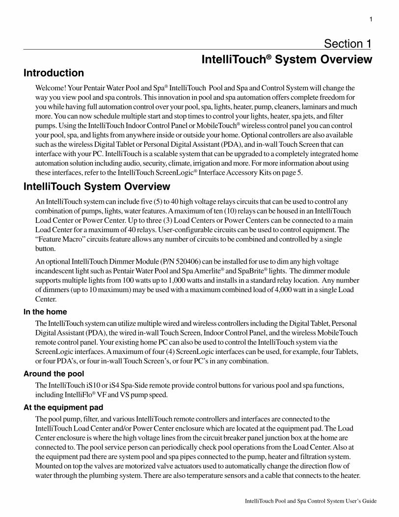
IntroductionWelcome! Your Pentair Water Pool and Spa® IntelliTouch Pool and Spa and Control System will change theway you view pool and spa controls. This innovation in pool and spa automation offers complete freedom foryou while having full automation control over your pool, spa, lights, heater, pump, cleaners, laminars and muchmore. You can now schedule multiple start and stop times to control your lights, heater, spa jets, and filterpumps. Using the IntelliTouch Indoor Control Panel or MobileTouch® wireless control panel you can controlyour pool, spa, and lights from anywhere inside or outside your home. Optional controllers are also availablesuch as the wireless Digital Tablet or Personal Digital Assistant (PDA), and in-wall Touch Screen that caninterface with your PC. IntelliTouch is a scalable system that can be upgraded to a completely integrated homeautomation solution including audio, security, climate, irrigation and more. For more information about usingthese interfaces, refer to the IntelliTouch ScreenLogic® Interface Accessory Kits on page 5.
IntelliTouch System OverviewAn IntelliTouch system can include five (5) to 40 high voltage relays circuits that can be used to control anycombination of pumps, lights, water features. A maximum of ten (10) relays can be housed in an IntelliTouchLoad Center or Power Center. Up to three (3) Load Centers or Power Centers can be connected to a mainLoad Center for a maximum of 40 relays. User-configurable circuits can be used to control equipment. The“Feature Macro” circuits feature allows any number of circuits to be combined and controlled by a singlebutton.
An optional IntelliTouch Dimmer Module (P/N 520406) can be installed for use to dim any high voltageincandescent light such as Pentair Water Pool and Spa Amerlite® and SpaBrite® lights. The dimmer modulesupports multiple lights from 100 watts up to 1,000 watts and installs in a standard relay location. Any numberof dimmers (up to 10 maximum) may be used with a maximum combined load of 4,000 watt in a single LoadCenter.
In the homeThe IntelliTouch system can utilize multiple wired and wireless controllers including the Digital Tablet, PersonalDigital Assistant (PDA), the wired in-wall Touch Screen, Indoor Control Panel, and the wireless MobileTouchremote control panel. Your existing home PC can also be used to control the IntelliTouch system via theScreenLogic interfaces. A maximum of four (4) ScreenLogic interfaces can be used, for example, four Tablets,or four PDA’s, or four in-wall Touch Screen’s, or four PC’s in any combination.
Around the poolThe IntelliTouch iS10 or iS4 Spa-Side remote provide control buttons for various pool and spa functions,including IntelliFlo® VF and VS pump speed.
At the equipment padThe pool pump, filter, and various IntelliTouch remote controllers and interfaces are connected to theIntelliTouch Load Center and/or Power Center enclosure which are located at the equipment pad. The LoadCenter enclosure is where the high voltage lines from the circuit breaker panel junction box at the home areconnected to. The pool service person can periodically check pool operations from the Load Center. Also atthe equipment pad there are system pool and spa pipes connected to the pump, heater and filtration system.Mounted on top the valves are motorized valve actuators used to automatically change the direction flow ofwater through the plumbing system. There are also temperature sensors and a cable that connects to the heater.

IntelliTouch Pool and Spa Control System User’s Guide
2
IntelliTouch System ComponentsThe main required components of an IntelliTouch system is a Load Center or Power Center, IntelliTouchPersonality Kit, and Interface:
Load or Power Center• Load Center: Provides a larger footprint (17" W x 23" H) Includes built-in sub panel (125 AMPS) capable
of holding up to eight 1” breakers. Also includes five 25 AMP three HP relays, 110/240 V transformer withsecondary side circuit protection. Multiple knockouts for different sizes of conduit are supplied as well as aGFCI side knockout. The Load Center provides ample space for all high and low voltage wiring needs.
• Power Center: Offers a smaller footprint (17" W x 17" H) than the Load Center. The Power Center doesnot include a circuit breaker base. Users should choose this enclosure if they already have existing circuitbreakers/sub-panel for their equipment.
• Expansion Kits: Models i5X and i10X, offer five or ten additional Auxiliary Circuits for systems i9+3,i9+3S and i10+3D. Each IntelliTouch Expansion Kit requires a Load Center (P/N 520136) or Power Center(P/N 520137). Up to three Expansion Kits and Load or Power Centers may be added to a system, forcontrol of up to 38 Auxiliary Circuits (40 auxiliary circuits for i10+3D).
IntelliTouch Personality KitsThere are several types of IntelliTouch control systems available for different pool/spa configurations:
• Shared Equipment: Pool and spa combinations with shared filtration system – Pool owners can enjoythe convenience of motorized valves for water flow separation between pool and spa. The Personality Kitmodels are:
• i5+3 (P/N 520505) – Four auxiliary circuits plus filter pump operation (create a Feature circuitfor valve actuators without using an existing output auxiliary circuit, and special light functions forcolor lighting). Five relays are included in the Load Center.
• i7+3 (P/N 520507) – Six auxiliary circuits plus filter pump operation and the +3 option (create aFeature circuit for valve actuators without using an existing output auxiliary circuit, and speciallight functions for color lighting). Two relays are included in the kit and five in the Load Center.
• i9+3 (P/N 520509) – Eight auxiliary circuits plus filter pump operation and the +3 option (createa Feature circuit for valve actuators without using an existing output auxiliary circuit, and speciallight functions for color lighting). Four relays are included in the kit and five in the Load Center.
• Dual Equipment: Pool and Spa with Dual Sets of Equipment – The IntelliTouch i10+3D(P/N 520510) is designed to operate two sets of pool equipment. Each set of a equipment (Pool or Spa) cancontrol one temperature setting. This IntelliTouch Personality Kit can control up to 10 pumps and/or lightingcircuits, plus two heater circuits. The Personality Kit includes, eight auxiliary circuits plus a filter pump.The +3 option (create a Feature Macro circuit for valve actuators without using an existing output auxiliarycircuit). Five relays are included in the kit and five in the Load Center. You can create a Feature circuit forvalve actuators without using an existing output auxiliary circuit, and special light functions for color lighting.
• Single Equipment: Pool Only or Spa Only Applications – The IntelliTouch i5S+3 (P/N 520506) andi9+3S provide advanced automation for a single body of water. The i5S+3 Personality Kits includes fourauxiliary circuits plus filter pump operation. Five relays are included in the Load Center. The i9+3S (P/N520508) Personality Kits includes eight auxiliary circuits plus filter pump operation and the +3 option (createa Feature Macro circuit for valve actuators without using an existing output aux circuit). Four relays areincluded in the kit and five in the Load Center. You can create a Feature circuit for valve actuators withoutusing an existing output auxiliary circuit, and special light functions for color lighting. This model also allowsHI-TEMP and LO-TEMP settings.

3
IntelliTouch Pool and Spa Control System User’s Guide
In-Wall Touch Screen
PDA
Indoor Control PanelMobileTouch Wireless Controller
IntelliTouch InterfacesChoose one or more of the following interface options to control pool and spa operations.
• iTC15 Kit (P/N 520500) – Includes Protocol Interface Adapter and wireless router that connects to existingDesktop or Laptop PC. This allows control of IntelliTouch pool and spa systems via PC (requires PC withan Ethernet connection, and Windows XP operating system).
• iTC25 Kit (P/N 520501) – Includes Wireless Personal Digital Assistant (PDA) with3.5" color touch screen custom configured for IntelliTouch systems, wireless router, anda Protocol Interface Adapter.
• iTC35 Kit (P/N 520502) – Includes in-wall color touch screen with Ethernet (RJ45)connection and Protocol Interface Adapter and wireless router. The in-wall Touchscreen is custom configured for IntelliTouch systems. Requires an Ethernet cable torouter.
• iTC45 Kit (P/N 520503) – Includes wireless Tablet with color touch screen, ProtocolInterface Adapter, and wireless router. The Tablet is custom configured for IntelliTouchsystems.
• Indoor Control Panel (P/N 520138) – 3.75’’ monochrome backlit LCDcontrol panel. Connects to the Personality board in the Load Center.
• MobileTouch Kit (P/N 520906) – 3.75’’ monochrome backlit LCD wirelesscontrol panel with Transceiver antenna. Allows any IntelliTouch wired systemto also have a wireless remote with all the capabilities of the Indoor ControlPanel. With an average range of 300 feet, pool owners have system controlanywhere around the home or yard. Powered by a rechargeable lithium-ionbattery. Includes a cradle for recharging. The MobileTouch control panelwithout the Transceiver antenna (P/N 520907) is also available.
• QuickTouch® Wireless Remote (QT4) - (P/N 520148): Four-functionwireless remote for pool and spa functions of your choice. Thiscontroller transmitter operates up to 150 feet range from the LoadCenter or Power Center.
• iS10 and iS4: 10-function (iS10) and 4-function (iS4) Spa-Sideremote controller for pool and spa functions, including increasing ordecreasing IntelliFlo VF or VS pump speed. The controllers canoperate up to 150 feet range from the Load or Power Center.
• i-Link™ Protocol Interface Adapter (P/N 520442): Allows homeautomation systems such as Crestron®, AMX®, Liton™ and others tocontrol IntelliTouch.
i-Link™ HomeAutomationProtocolInterfaceAdapter QuickTouch® wireless
remote (QT4)
Digital Tablet

IntelliTouch Pool and Spa Control System User’s Guide
4
Personal Computer (PC): Existing home owner’s PC or Laptop. Connects to a wireless router and the IntelliTouchProtocol adapter for control of IntelliTouch pool/spa systems. Requires a PC/Laptop (Windows XP) with Ethernet/RJ45 adapter installed.
Personal Digital Assistant (PDA): This wireless PDA with a color touch screen enables you to control your pooland spa features using the IntelliTouch ScreenLogic interface. The PDA is custom configured for IntelliTouchsystems.
In-wall Touch Screen: A color display with Ethernet (RJ45) connector. Connects to the provided wireless routerand Protocol adapter via Ethernet (RJ45) for control of IntelliTouch pool and spa systems. The in-wall TouchScreen is custom configured for IntelliTouch systems.
Wireless Tablet: This control panel consists of a color touch screen. Receives and transmits commands viawireless router and Protocol adapter for control of IntelliTouch pool/spa systems. The Tablet is custom configuredfor IntelliTouch systems.
Indoor Control Panel: This control panel consists of a 3.75’’ monochrome backlit LCD and connects to thePersonality Board in the Load Center or Power Center for control of IntelliTouch pool and spa systems.
MobileTouch: This wireless control panel has a 3.75’’ monochrome backlit LCD. Receives and transmitscommands via the Transceiver antenna located at the Load or Power Center.
Wireless router: Connects to the PC or Laptop via Ethernet connection to the Protocol adapter.
Protocol adapter: Connects to wireless router via Ethernet connection and to Personality board (Load/PowerCenter) via a four-wire 22-AWG cable.
Load Center or Power Center. The main control center. Includes the Outdoor Control Panel that controls pump,heater, and light relays. Receives commands via Protocol adapter, and wireless and wired control panelsconnected to the Personality board.
MobileTouch Transceiver antenna: Connects to the Personality circuit board. Sends and receives commands toand from the MobileTouch wireless control panel.
10
95
7
8
1
3
4
2 6
IntelliTouch in and around your home
1
2
3
4
5
6
7
8
9
10
5
IntelliTouch Pool and Spa Control System User’s Guide
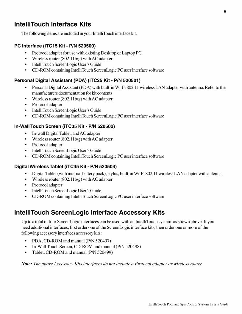
IntelliTouch Interface KitsThe following items are included in your IntelliTouch interface kit.
PC Interface (iTC15 Kit - P/N 520500)• Protocol adapter for use with existing Desktop or Laptop PC• Wireless router (802.11b/g) with AC adapter• IntelliTouch ScreenLogic User’s Guide• CD-ROM containing IntelliTouch ScreenLogic PC user interface software
Personal Digital Assistant (PDA) (iTC25 Kit - P/N 520501)• Personal Digital Assistant (PDA) with built-in Wi-Fi 802.11 wireless LAN adapter with antenna. Refer to the
manufacturers documentation for kit contents• Wireless router (802.11b/g) with AC adapter• Protocol adapter• IntelliTouch ScreenLogic User’s Guide• CD-ROM containing IntelliTouch ScreenLogic PC user interface software
In-Wall Touch Screen (iTC35 Kit - P/N 520502)• In-wall Digital Tablet, and AC adapter• Wireless router (802.11b/g) with AC adapter• Protocol adapter• IntelliTouch ScreenLogic User’s Guide• CD-ROM containing IntelliTouch ScreenLogic PC user interface software
Digital Wireless Tablet (iTC45 Kit - P/N 520503)• Digital Tablet (with internal battery pack), stylus, built-in Wi-Fi 802.11 wireless LAN adapter with antenna.• Wireless router (802.11b/g) with AC adapter• Protocol adapter• IntelliTouch ScreenLogic User’s Guide• CD-ROM containing IntelliTouch ScreenLogic PC user interface software
IntelliTouch ScreenLogic Interface Accessory KitsUp to a total of four ScreenLogic interfaces can be used with an IntelliTouch system, as shown above. If youneed additional interfaces, first order one of the ScreenLogic interface kits, then order one or more of thefollowing accessory interfaces accessory kits:
• PDA, CD-ROM and manual (P/N 520497)• In-Wall Touch Screen, CD-ROM and manual (P/N 520498)• Tablet, CD-ROM and manual (P/N 520499)
Note: The above Accessory Kits interfaces do not include a Protocol adapter or wireless router.

IntelliTouch Pool and Spa Control System User’s Guide
6
Blank Page
7
IntelliTouch Pool and Spa Control System User’s Guide
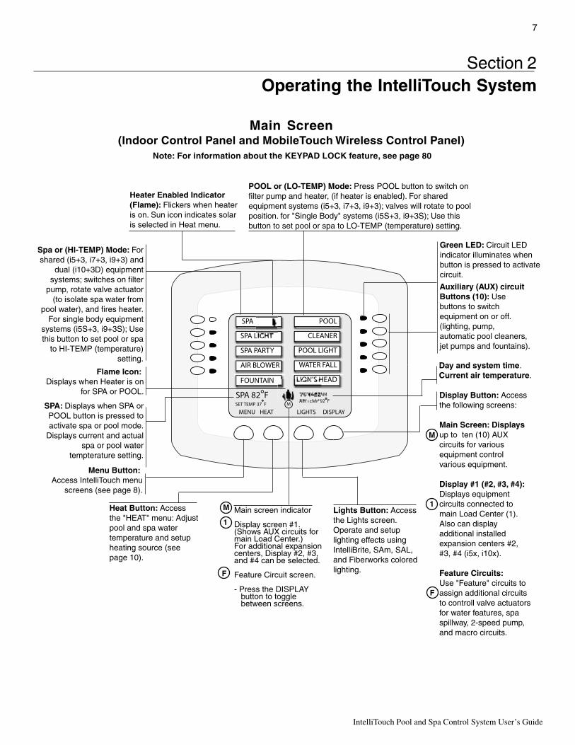
Heater Enabled Indicator(Flame): Flickers when heateris on. Sun icon indicates solaris selected in Heat menu.
Spa or (HI-TEMP) Mode: For shared (i5+3, i7+3, i9+3) and
dual (i10+3D) equipment systems; switches on filter
pump, rotate valve actuator (to isolate spa water from
pool water), and fires heater. For single body equipment
systems (i5S+3, i9+3S); Use this button to set pool or spa
to HI-TEMP (temperature) setting.
POOL or (LO-TEMP) Mode: Press POOL button to switch on filter pump and heater, (if heater is enabled). For shared equipment systems (i5+3, i7+3, i9+3); valves will rotate to pool position. for "Single Body" systems (i5S+3, i9+3S); Use this button to set pool or spa to LO-TEMP (temperature) setting.
Auxiliary (AUX) circuit Buttons (10): Use buttons to switch equipment on or off. (lighting, pump, automatic pool cleaners, jet pumps and fountains).
SPA: Displays when SPA or POOL button is pressed to activate spa or pool mode.
Displays current and actual spa or pool water
tempterature setting.
Menu Button: Access IntelliTouch menu
screens (see page 8).
Heat Button: Access the "HEAT" menu: Adjust pool and spa water temperature and setup heating source (see page 10).
Lights Button: Access the Lights screen. Operate and setup lighting effects using IntelliBrite, SAm, SAL, and Fiberworks colored lighting.
Display Button: Access the following screens:
Main Screen: Displays up to ten (10) AUX circuits for various equipment control various equipment.
Display #1 (#2, #3, #4): Displays equipment circuits connected to main Load Center (1). Also can display additional installed expansion centers #2, #3, #4 (i5x, i10x). Feature Circuits: Use "Feature" circuits to assign additional circuits to controll valve actuators for water features, spa spillway, 2-speed pump, and macro circuits.
1
F
Main screen indicator
Display screen #1. (Shows AUX circuits for main Load Center.) For additional expansion centers, Display #2, #3, and #4 can be selected.
Feature Circuit screen.
- Press the DISPLAY button to toggle between screens.
1
M
F
Flame Icon: Displays when Heater is on
for SPA or POOL.
M
Green LED: Circuit LED indicator illuminates when button is pressed to activate circuit.
Day and system time.Current air temperature.
Section 2Operating the IntelliTouch System
Main Screen(Indoor Control Panel and MobileTouch Wireless Control Panel)
Note: For information about the KEYPAD LOCK feature, see page 80
IntelliTouch Pool and Spa Control System User’s Guide
8
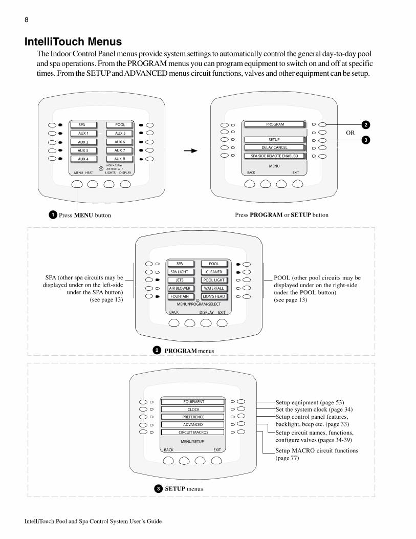
IntelliTouch MenusThe Indoor Control Panel menus provide system settings to automatically control the general day-to-day pooland spa operations. From the PROGRAM menus you can program equipment to switch on and off at specifictimes. From the SETUP and ADVANCED menus circuit functions, valves and other equipment can be setup.
7
8
MENU/PROGRAM/SELECT
DISPLAY EXITBACK
MENU/SETUP
BACK EXIT
EQUIPMENT
CLOCK
PREFERENCE
ADVANCED
CIRCUIT MACROS
Press MENU button
PROGRAM menus
SETUP menus
POOL (other pool circuits may bedisplayed under on the right-sideunder the POOL button)(see page 13)
Setup equipment (page 53)Set the system clock (page 34)Setup control panel features,backlight, beep etc. (page 33)Setup circuit names, functions,configure valves (pages 34-39)
1
2
3OR
SPA (other spa circuits may bedisplayed under on the left-side
under the SPA button)(see page 13)
Press PROGRAM or SETUP button
2
3
Setup MACRO circuit functions(page 77)

9
IntelliTouch Pool and Spa Control System User’s Guide
Indoor Control Panel Menus
14
53
34
33
7733
53
54
56-69
71
72
72
7
38
34
39
78
35
76
35-36
75
78
81
12
78
44 44
12
42
46
80
73
INTELLITOUCH INDOOR CONTROL PANEL BUTTONS
Pg.
Also see page 42
THERMALFLO - Pg. 70
SOLAR/MAN HEAT-Pg. 74
MAGIC STREAMTHUMPER - TOGGLE
RESET - HOLD / STOP
46
KEYPAD LOCKPg. 80
DEGREES C/F - Pg. 74

IntelliTouch Pool and Spa Control System User’s Guide
10
Heating your Spa and PoolFrom the Heat screen, use Spa button (left side) or Pool button (right side) to adjust the heat temperature foryour spa or pool. You can also switch the heater on or off from this screen. For single-body systems (modelsi5S+3 and i9+3S), spa and pool are replaced with HI-TEMP and LO-TEMP settings (for more informationsee page 7).
Adjust Spa or Pool Heat Settings
To adjust the spa or pool set point temperature, go to the Heat screen:
Note: Be sure the Spa Mode does not display “OFF.” If “OFF” is displayed, refer to “Configuringthe Heating System Options,” page 11, for more information.
To adjust the spa or pool set point temperature, press the HEAT button at the bottom of the screen:
• SPA: Press the spa Up or Down buttons (top left and right side) to raise or lower the spa water temperature.The set point water temperature is displayed in the middle of the screen. The spa temperature setting can beadjusted from 40° F to 104° F or (4° C to 40° C).
• POOL: Press the pool Up or Down buttons (third down from the top, left and right side) to raise or lowerthe pool temperature. The set point water temperature is displayed in the middle of the screen. The pooltemperature setting can be adjusted from 40° F to 104° F or (4° C to 40° C).
1. Press the Set button to save the set point temperature settings. The current spa and pool water temperaturesare displayed on the main screen (see page 7).
2. Press the Back button to return to the Main screen.
HEAT
Getting There
SPA
Press to lower SPA temperatureHi-Temp Mode for i5S and i9+3S
Press to increase SPA temperature
Press to lower POOL temperature Press to increase POOL temperatureHi-Temp Mode for i5S and i9+3S
Back button Set button

11
IntelliTouch Pool and Spa Control System User’s Guide
Selecting the Heating SystemUse the heat menu settings to specify the set point temperature and select the heat source to heat the pool andspa water. The water will begin to heat when the heater is manually switched on, by pressing the Pool, Spabutton on the Indoor Control Panel or the Valves (V) button on the Outdoor Control Panel, regardless of theheater selection (off) in the Heat menu. The optional iS10 Spa-Side remote, iS4 Spa Side remote orQuickTouch QT4 wireless remote can be used to switch the heater on. The IntelliTouch system supports gas,electric and solar heating systems. IntelliTouch will use the heating source that is selected. Multiple heaters aresupported. IntelliTouch automatically selects the heating system that is most effective for the user settings. Theheat source selections are:
To select the heating system, press the HEAT button at the bottom of the screen.
• SPA: Press the left or right side button next to SPA MODE to select the heating mode for the spa.
• POOL: Press the left or right side button next to POOL MODE to select the heating mode for the spa.
1. Press the Set button to save the heat settings.
2. Press the Back button to return to the Main screen.
The heat options are:
• OFF - No heating even though pump and other circuits may be operating.
• HEATER - Gas heater only. When the heater is active it will continue heating the water until the heater’scurrent highest set point temperature triggers the heater sensor (104° F or 40° C). Do not activate the heaterwithout running the pump. The heater will not run if water flow is not detected.
• HEAT PUMP - Heat pump only.
• H PUMP PREF. - For when a heat pump is in combination with other heating systems and you want to usethe heat pump only when it is most effective.
HEAT
Getting There
SPA Press to scroll through SPA Heatingoptions: OFF, HEATER. If solar isenabled (see page 71, 74) theoptions are HEAT PUMP, H PUMPPREF.Press to scroll through POOLHeating options: OFF, HEATER. Ifsolar is enabled the options areHEAT PUMP, H PUMP PREF.
Back button Set button
IntelliTouch Pool and Spa Control System User’s Guide
12
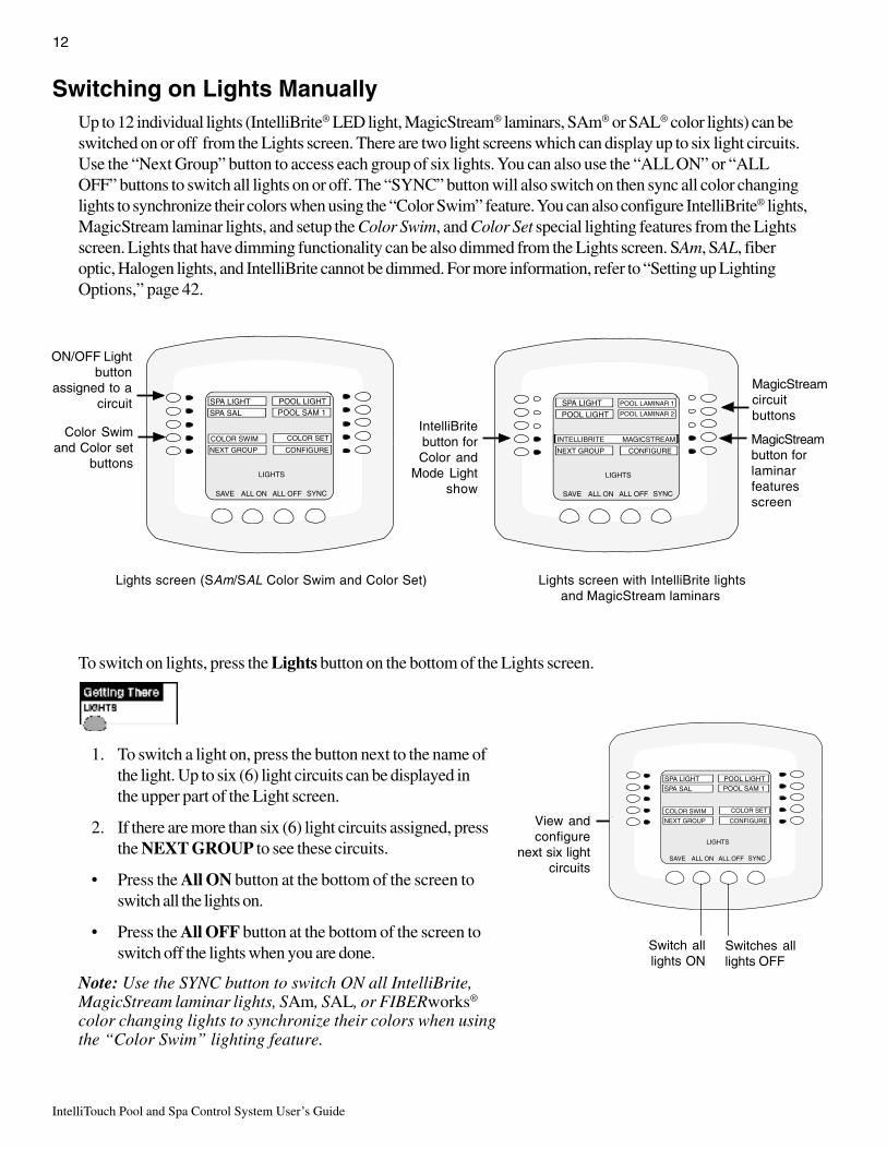
Switching on Lights ManuallyUp to 12 individual lights (IntelliBrite® LED light, MagicStream® laminars, SAm® or SAL® color lights) can beswitched on or off from the Lights screen. There are two light screens which can display up to six light circuits.Use the “Next Group” button to access each group of six lights. You can also use the “ALL ON” or “ALLOFF” buttons to switch all lights on or off. The “SYNC” button will also switch on then sync all color changinglights to synchronize their colors when using the “Color Swim” feature. You can also configure IntelliBrite® lights,MagicStream laminar lights, and setup the Color Swim, and Color Set special lighting features from the Lightsscreen. Lights that have dimming functionality can be also dimmed from the Lights screen. SAm, SAL, fiberoptic, Halogen lights, and IntelliBrite cannot be dimmed. For more information, refer to “Setting up LightingOptions,” page 42.
To switch on lights, press the Lights button on the bottom of the Lights screen.
1. To switch a light on, press the button next to the name ofthe light. Up to six (6) light circuits can be displayed inthe upper part of the Light screen.
2. If there are more than six (6) light circuits assigned, pressthe NEXT GROUP to see these circuits.
• Press the All ON button at the bottom of the screen toswitch all the lights on.
• Press the All OFF button at the bottom of the screen toswitch off the lights when you are done.
Note: Use the SYNC button to switch ON all IntelliBrite,MagicStream laminar lights, SAm, SAL, or FIBERworks®
color changing lights to synchronize their colors when usingthe “Color Swim” lighting feature.
View andconfigure
next six lightcircuits
LIGHTS
ALL OFF SYNCSAVE ALL ON
CONFIGURE
POOL SAM 1POOL LIGHT
NEXT GROUP
SPA LIGHTSPA SAL
COLOR SET COLOR SWIM
Switch alllights ON
Switches alllights OFF
LIGHTS
ALL OFF SYNCSAVE ALL ON
CONFIGURE
POOL SAM 1POOL LIGHT
NEXT GROUP
SPA LIGHTSPA SAL
COLOR SET COLOR SWIM
Lights screen (SAm/SAL Color Swim and Color Set)
ON/OFF Lightbutton
assigned to acircuit
Color Swimand Color set
buttons
MagicStreamcircuitbuttons
Lights screen with IntelliBrite lights and MagicStream laminars
IntelliBritebutton forColor and
Mode Lightshow
LIGHTS
ALL OFF SYNCSAVE ALL ON
CONFIGURE
POOL LIGHT
NEXT GROUP
INTELLIBRITE MAGICSTREAM
SPA LIGHT POOL LAMINAR 1
POOL LAMINAR 2
MagicStreambutton forlaminarfeaturesscreen

13
IntelliTouch Pool and Spa Control System User’s Guide
Special Lighting FeaturesAt least two (2) Pentair Water Pool and Spa IntelliBrite, SAm and/or SAL, and/or FIBERworks lightingsystems are required to use the Color Swim, Color Set and Sync special lighting features. Up to twelve (12)lights can be independently controlled from the Lights screen.
SAm, SAL, or FIBERworks lighting special lighting features:
Note: The IntelliBrite Color Swim and Color Set (SAm Style) feature is accessed from the Lightsscreen. See page 46 for more information.
• Color Swim - Presets the light circuit to transition through colors in sequence. This gives the appearance ofcolors dancing through the water. You can adjust the delay of each light to make the colors move at differentspeeds. This feature requires a separate relay for each light.
• Color Set - Presets the light circuit to a specific colors. This feature requires a separate relay for each light.
• Sync - Switches on all IntelliBrite, SAm, SAL, or FIBERworks color changing lights to synchronize theircolors.
Note: For SAm and SAL lighting setup information, see “Setting up Lighting Options,” on page 42.
To activate the special lighting features, press the Lights button on the bottom of the main screen.
Light buttons:
• Press the COLOR SWIM button to start the changing color lights feature.
• Press the COLOR SET button to set all lights to a pre-programmed color.
• Press the SYNC button to switch on all color changing lights to synchronize colors.
• To configure lights on this screen press the CONFIGURE button.
Note: Depending on what kind of light is being activated and what mode it was in previously, it maytake up to a minute or more after the Color Set, Color Swim, or Sync button is pressed to activatethe feature.
Switches all SAm, SAL andFiberworks lights ON andSynchronizes lights
Switch COLOR SWIM ON.Pressing the button again willnot switch COLOR SWIM OFF.
Use the ALL OFF button
Switch COLOR SET ON.Pressing the button again willnot switch COLOR SET OFF.Use the ALL OFF button
“Color Set” buttons for assignedlight circuits
LIGHTS
ALL OFF SYNCSAVE ALL ON
CONFIGURE
POOL SAM 1POOL LIGHT
NEXT GROUP
SPA LIGHTSPA SAL
COLOR SET COLOR SWIM
Switch on all color changinglights to synchronize colors

IntelliTouch Pool and Spa Control System User’s Guide
14
Dimming LightsIn order to dim lights, the Dimmer Module (P/N 520406) must be installed by a qualified electrician in theIntelliTouch Load Center or Power Center. Only incandescent tungsten filament lights can be dimmed (notHalogen lights). Lights that have dimming functionality can be dimmed from the Lights screen. SAm or SAL fiberoptic, Halogen lights, and IntelliBrite cannot be dimmed. For more information, refer to “Setting up LightingOptions,” page 42. The circuit must be assigned to the “Dimmer” circuit function (see page 41) in order tooperate correctly.
To dim lights, go to the assigned circuit name:
1. Press the button next to the circuit name. A light should comeon and be switched on at the specified dimming level.
2. To change the dimming level, hold the circuit button down untilthe Dimmer Level Settings screen displays as shown.
3. Press the button next to Decrease to decrease the dimminglevel, and the button next to Increase to increase the dimminglevel. The percent value displays the current dimming levelsetting.
4. Press Save when done. The light will adjust to the set dimminglevel.
Note: Macros can turn on light dimming circuits, but lights cannot be dimmed through the macro.The dimming level must be changed for each light dimming circuit.
Setting ON/OFF Times for Equipment (PROGRAM)You can create schedules to automatically run equipment like pool filtration or lights. Any circuit can be set toswitch on and off on every day of the week. When a relay is switched on manually, it remains on until you eitherswitch it off manually, or the next time the relay is scheduled to be switched off. For example, if the filter pump orany circuit is scheduled to run from 9AM to 4 PM and the programmed schedule is turned OFF at 1:00 PM andthen turned on at 1:10 PM, the circuit will turn OFF at its programmed OFF time of 4:00 PM. But if the circuit isturned on after 4:00 PM, the factory set Egg Timer of 12 hours is now engaged. So if the circuit was turned on at6:00 PM that circuit will turn off at 6:00 AM (12 hours later). If the circuit was turned ON at 5:00 PM andbecause a programmed OFF time had been set to turn off at 4:00 PM, the circuit would operate for 11 hours. Aspa or pool program can be overridden using the Spa or Pool button to switch the circuit on.
From the “Program” screen, you can schedule IntelliTouch to automatically run equipment like pool filtration orlights. Any circuit (auxiliary, feature, or macro) can be scheduled to switch on and off at a specific time and on aany day(s) of the week. Up to 99 total programs may be created for all circuits combined.
Schedule a program: The “Program” screen displays a program counter in the upper right (1/0) side of thescreen. This counter indicates the current number of scheduled programs. After setting the start and stop time andthe day(s) to run the first scheduled program, press Save to view the first program (1/1) and increment the counterto next program. To access the next program screen, press the button next to the counter label (2/1). Set the startand stop time and the day(s) to run the second scheduled program (2/1). Repeat this process to enter anotherprogram. For example, 2/3 indicates that you are viewing program 2 of 3 total programs saved for that circuit. 4/3 indicates that you are creating program 4 but only 3 are currently saved. After pressing the Save button, thecounter updates to 4/4. Press the button to the right of the label counter to step through each program first thendisplay the unsaved program screen. The following describes how to program equipment to run the pool filtrationsystem. This process is the same for any installed equipment listed on the screen.
MENU SETUP ADVANCED CIRCUIT FUNCTION (NAME)
Getting There
DIMMER LEVEL SETTINGS
60%
DIMMER CIRCUIT AUX1
EXIT

15
IntelliTouch Pool and Spa Control System User’s Guide
Go to the PROGRAM/SELECT equipment screen. From this screenyou can select SPA, POOL or any of the AUX equipment circuits toprogram.
1. Press the top right button next to POOL to access the “Program”screen to program the pool equipment.
2. To set the start time: Press the left side button next to HOURS(and the start flag icon) to set the start hour. Press the right sidebutton to set the minutes for the start time. To use the“EGGTIMER” feature, see page 17.
3. To set the stop time: Press the left side button to HOURS (andthe stop icon) to set the hour to stop the program. Press the rightside button to set the minutes for the stop time. To use the “ONCEONLY” feature, see page 16.
4. Press the left side button next to DAYS to specify the day(s) to runthe program one time. Choose “EVERYDAY” to run the programone time each day of the five days. To choose specific days to runthe program, press the button next to DAYS. The days of theweek screen displays. The LED lights next to the days of the weekwill all be lit. To switch off a day, press the button next to thedisplayed day. The light switches is off. To set all day on, all lightsshould be on. Press Save to save the setting. The previous screen will be displayed.
5. Press Save to save the current program. The program counter displays (1/1) indicating that you have savedone (1) program for the selected circuit. To erase a program press the Clear button then Save.
6. Press the Back button to return to the SPA, POOL and AUX equipment selection screen to choose otherequipment. Press the Exit button to return to the main screen.
Smart Start (Setting up SAm, SAL and IntelliBrite lights)Smart Start (SS_Yes/SS_No) - When a light circuit function is setup asa SAM , SAL or IntelliBrite light, use the Smart Start feature (SS_Yes) toautomatically begin changing colors when the light circuit is switch on.Smart Start can also be assigned to all other special light circuits(i.e. Color Wheel, Photon Generator®, Light, see page 41).
1. Press the top right button next to SAM LIGHT to program thelight circuit. For this example the SAL LIGHT circuit name hasalready been selected from the Circuit Names list (see page 37).
2. SS_Yes/SS_No displays next to the light circuit name.3. Smart Start displays at the bottom of the screen. Press the button
on the bottom of the screen to toggle between SS_Yes andSS_No. Select SS_Yes to automatically begin changing colorswhen the light circuit is switch on.
4. Setup each light circuit as described above in steps 2 - 5.
MENU PROGRAM POOL
Getting There
(or any other circuit)
SS_NO
SMARTSTART
SS_YESSAL LIGHT
SMARTSTART SAVE
MENU/PROGRAM/SAM LIGHT
CLEARBACK

IntelliTouch Pool and Spa Control System User’s Guide
16
Using the Once Only TimerThe “Once Only” programming feature enables IntelliTouch to automatically switch equipment on for one timeonly. For example, you can set to have the spa and heater switch on before you get home from work for oneevening. Unlike a regular scheduled program, the “Once Only” program does not repeat.
Go to the PROGRAM/SELECT equipment screen. From this screenyou can select SPA, POOL or any of the AUX equipment circuits toprogram.
The following example describes how to program the spa filter pump andheater to switch on at a specific time:
1. Press the button next to SPA to access the “Program/Select”screen. If this is the first program, the program counter displays(1/0). After this program is saved, (1/1) is displayed (see step 5).Up to 99 total programs may be created for all circuits combined.
2. Press the left side button next to HOURS and select ONCEONLY (Once Only is displayed one press after 11:00 PM).
3. Press the left side button next to HOURS to set the start time.
Note: Press the button under CLEAR to reset the default settings.
4. Press the left side button next to DAYS to specify the day(s) to runthe program one time. Choose “EVERYDAY” to run the programone time each day of the five days. If the time you are setting haspassed for today, the “Once Only” program is set for the next day.To choose specific days to run the program, press the button nextto DAYS. The days of the week screen displays. The LED lightsnext to the days of the week will all be lit. To switch off a day,press the button next to the displayed day. The light switches is off.To set all day on, all lights should be on. Press Save to save thesetting. The previous screen will be displayed.
5. Press Save to save the current program. The program counterdisplays (1/1) indicating that you have saved one (1) program forthe selected circuit.
6. Press the Back button to return to the SPA, POOL and AUX equipment selection screen to choose otherequipment.
7. Press the Exit button to return to the main screen.
SS_NO
SMARTSTART
SPA
ONCE ONLY
1/0
MENU/PROGRAM/SPA
MENU/PROGRAM/SELECT
DISPLAY EXITBACK

17
IntelliTouch Pool and Spa Control System User’s Guide
Setting the Egg Timer FunctionThe “Egg Timer” feature lets you manually switch on equipment and switch off automatically after a specifiedtime. You can set this timer feature for other equipment such as lighting, the spa, or the spa jets. Equipment canbe programmed to be switched on for one minute to 24 hours. You can also use the “Don’t Stop” feature tooverride the 12 hour default switch off time, and run continuously until manually switched off.. If you have neverset the timer for a specific piece of equipment, the factory default time is set to 12 hours.
If you have a power outage, this feature will not switch the equipment back on, you need to use set the systemin “Service” mode at the outdoor control panel center to switch the equipment back on. For more information,refer to “Using the Service Personnel Screen” on page 82.
Go to the PROGRAM/SELECT equipment screen. From this screenyou can select SPA, POOL or any of the AUX equipment circuits toprogram.
The following example describes how to program the spa equipmentusing the “Egg Timer” feature:
1. To program the spa filter pump and heater to switch on and off at aspecific time, press the button next to SPA to access the “Program/Select” screen. If this is the first program, the program counterdisplays (1/0). After this program is saved, (1/1) is displayed (seestep 6). Up to 99 total programs may be created for all circuitscombined.
2. Press the left side button next to HOURS until EGG TIMER isdisplayed. (EGG TIMER is displayed one press after 11:00 PM).
3. Press the left side button next to HOURS (under EGG TIMER)to set the count down run time in hours (from 00:00 to 23:00hours). You can also select “DON’T STOP” to run the circuitcontinuously until switched off manually. “DON’T STOP” isdisplayed one press after 23:00.
4. Press the right side button next to MINS to set the run timeminutes.
Note: Press the button under CLEAR to reset the default settings.
5. For the “Egg Timer” feature ALWAYS is displayed, indicating the program will run and automatically shut-offin the specified time.
6. Press Save to save the current program. The program counter displays (1/1) indicating that you have savedone (1) program for the selected circuit.
7. Press the Back button to return to the SPA, POOL and AUX equipment selection screen to program otherequipment.
8. Press the Exit button to return to the main screen.
SS_NO
SMARTSTART
ALWAYS
MENU/PROGRAM/SPA
1/0
EGGTIMER
SPA
MENU/PROGRAM/SELECT
DISPLAY EXITBACK

IntelliTouch Pool and Spa Control System User’s Guide
18
iS10 Spa-Side Remote ControllerAn iS10 Spa-Side remote controller can control up to ten functions including a spa temperature adjustment. Asmany as four iS10’s can be installed in i5+3, i5S+3, i7+3, i9+3, i9+3S, and i10+3D systems. The iS10 Spa-Side remote controller is listed UL (1563) for use with the IntelliTouch systems at the water’s edge. Five (5) in-line buttons control up to ten (10) system functions numbered one through five from left to right as shown (if thesystem allows). A label above or below the buttons identifies each circuit function. A “peanut-shaped” middlebutton toggles between which row of circuit functions will be activated when one of the five in-line buttons arepressed. A red status LED above and below the toggle button indicates which row (Top or Bottom) is active.When one of the in-line buttons is pressed, an adjacent red status LED will be on light, indicating that the circuithas been activated. The default circuits activated by each button are shown in the table below. The iS10includes an LED display shows the current spa water temperature. The spa temperature may be increased ordecreased by pressing the up or down arrow button located under the display. The temperature display willblink while being changed. After setting the desired temperature, the display will return to steady and show theactual temperature as it meets the set point. The temperature set by the iS10 is only temporary. Any twobuttons can be assigned to increase or decrease the IntelliFlo VF or VS pump’s flow (GPM) rate or speed(RPM). Each press of the button increases or decreases the pump’s flow rate or speed (see page 78) until theGPM or RPM is reached as specified in the IntelliFlo menu. When the Spa mode is switched OFF, thetemperature set at the Indoor Control Panel will resume the next time the spa mode is activated (see “ManualHeat” on page 74). The Spa Mode will automatically turn off after 24 hours. For iS10 setup and configurationinformation, see page 30 and 78.
iS10 Spa-Side Remote Controller
1nottuB,D3+01-,3+9i,3+7i,5i APS LOOP
S3+9i,S5i PMET-IH PMET-OL
nottuB 2 1XUA 5XUA
nottuB 3 2XUA 6XUA
nottuB 4 3XUA 7XUA
nottuB 5 4XUA 8XUA
Temperature LED Display
Temperature Down ButtonTemperature Up Button
Bottom Row Toggle Button
Top Row Toggle Button
Bottom RowLED Indicator
In-Line Button 1In-Line Button 2
In-Line Button 3In-Line Button 4
In-Line Button 5
Function LED Indicators
Top Row LED Indicator
Function LED Indicators
Note: IntelliFlo VF orVS pump flow rate(GPM) or speed(RPM) can becontrolled from anytwo iS10 buttons. Formore information, seepage 78.

19
IntelliTouch Pool and Spa Control System User’s Guide
MobileTouch Wireless ControllerThe MobileTouch wireless controller provides the same functionality as the IntelliTouch Indoor Control Panel. Ithas an operating range of up to 300 ft. from the MobileTouch transceiver antenna (line of sight) which istypically located near the IntelliTouch load center. The optimum wireless transmit and receive range may beaffected by physical obstructions, (especially those containing metal), weather conditions, and geographicalfeatures.
The MobileTouch controller screen is an LCD (liquid crystal display) which can be sensitive to sunlight. Whenexposed for extended periods the LCD screen will heat up and go black. If this happens, place the remote in ashaded area and allow the screen to cool down. Do not attempt to adjust the contrast or the screen will beunreadable when it eventually cools. When used outside, keep the remotecovered or in a shaded area. Prolonged exposure to sunlight maypermanently damage the unit.
WARNING! Do not plug in the AC adapter to a power source within five(5) feet of the pool and spa. Canadian installations require a minimum of (3)meters from pool water. Do not recharge outdoors. Only use Pentair WaterPool and Spa approved AC adapter transformer.
The MobileTouch wireless controller is water resistant and can be exposedto temporary splashing or wet hands. However, the controller is not intendedto be submersed. Remove unit immediately if it is dropped in the water orexposed to rain. Store the unit indoors in a dry environment. Be sure thegold charging contacts are dry before charging.
MobileTouch Wireless Controller (Previous Model)The previous model of the MobileTouch wireless controller and Transceiver antenna cannot be used with thelatest model of the MobileTouch wireless controller and Transceiver antenna. Both models cannot coexist in thesame IntelliTouch system.
iS4 Spa-Side Remote ControllerThe iS4 Spa-Side remote controller is a double-insulated, waterproof device that is UL (1563) listed forinstallation at the water’s edge. The iS4 is typically installed at the tile-line of the spa wall, or in the deck withinarm’s reach of a spa occupant. The iS4 provides remote switching of up to four control circuits from the spa ornearby location. Use the iS4 for switching on the spa pump and heater or other auxiliary equipment (i.e., lights,jet pump, air blower, etc.). The red LED status light glows steady when in spa mode and flashes while the spais heating. For iS4 button assignment information, see page 78.
iS4 Spa-Side Remote Controller(Wall or tile mount)
iS4 Spa-Side RemoteController (Deck mount)
1 2 3 4
Red power LEDindicator
3 2 1
Red powerLED indicator
4
MobileTouch WirelessController
Note: IntelliFlo VF or VS pumpflow rate (GPM) or speed(RPM) can be controlled fromany two iS4 buttons. For moreinformation, see page 78.

IntelliTouch Pool and Spa Control System User’s Guide
20
Charging the MobileTouch Wireless ControllerWhen you are not using the MobileTouch controller, place it in the cradle to recharge the battery. This allows thebattery to be fully charged at all times.
To charge the MobileTouch controller battery:
• Plug the AC adapter into an AC wall outlet. Insert the AC Adapter plug into the bottom of the cradle andplace the MobileTouch controller in the cradle. Note: When the MobileTouch controller is placed in thecradle the display and backlight will be on. After five minutes the backlight will shut off. TheMobileTouch controller and display are always on when seated in the cradle. To turn the backlight on,press any button.
Charging the battery:
• If the battery screen icon displays one or no bars or the screen is blank, this may indicate that the batterycannot power the device and needs recharging. During battery recharge, the battery icon bars scroll from rightto left. A complete battery charge takes about 3 to 4 hours. After a complete battery recharge, the batteryicon is replaced with a power plug icon, indicating the battery is fully charged and is now operating on ACpower from the cradle. Note: If the battery requires replacement, only use Pentair Water Pool and Spareplacement battery(P/N 520815Z).
Using the MobileTouch Wireless ControllerThe range of the MobileTouch wireless controller can be up to 300 feet from its transceiver antenna (line ofsight). The transceiver antenna is typically located outside near the IntelliTouch Load Center. The device can beused all day at full power with a complete battery charge (3 to 4 hours).
To use the MobileTouch wireless controller:
1. Remove the MobileTouch wireless controller from the cradle. The controller can also be used while seated inthe cradle with AC power connected to the cradle.
2. Press the Power button on the front right-side to switch the unit ON. The main screen is displayed. The LCDbacklight will turn off in five minutes if not in use. The battery icon displays three bars, indicating the battery isfully charged. Press the controller’s power switch to switch Off the device.
Sufficient charge left in thebatteries to operate device.
Cradle
Power On/Off button
MAIN SCREEN CHECK BATTERY ICONS
Ample battery charge. Barsscroll right to left duringbattery recharge.
Batteries will deplete soon.
Plug icon displays whenthe battery is fully chargedand device is operating onAC power from cradle.
MobileTouch Wireless Controller
Note: For details about enabling theMobileTouch wireless controller, refer to“Setting up the MobileTouch WirelessController,” page 28.

21
IntelliTouch Pool and Spa Control System User’s Guide
QuickTouch Wireless QT4 Remote ControllerThe QuickTouch QT4 wireless remote controller provides switching of up to fourcircuits. It is typically used for activating the spa circulation, and for operating threeauxiliary pieces of equipment (such as lights, jet pump, air blower, waterfall, etc.).
Each of the four functions on the QT4 remote controller has an ON and an OFFbutton. To switch a circuit on or off, press and hold the appropriate button for atleast a full second. For information about setting up the QT4 remote, see“Configuring Remote Control Button Circuits (iS4, iS10, QT4 QuickTouch, andPhone Remote), on page 78.
You can assign a circuit to any one of the four buttons. The factory default setup is::
• SPA button activates the spa circuit.
• A button activates Auxiliary 1 circuit.
• B button activates Auxiliary 2 circuit.
• C button activates Auxiliary 3 circuit.
Note: To control circuits other than Spa, AUX 1, AUX 2 and AUX 3, it is possible to makeadjustments through the Indoor Control Panel or MobileTouch wireless control panel.IMPORTANT: The QT4 remote may be used with wet hands, but should never be submersed inwater, as this could damage the unit. If accidental submersion occurs, dry unit out by removingbattery cover and removing battery. Position unit so that water can drain out. Replace the batterycover when the unit is completely dry.
QuickTouch QT4Wireless RemoteController
IntelliChlor® Salt Chlorine Generator(Accessory)
The IntelliChlor salt chlorinator uses a process known as electrolysisto produce Sodium Hypochlorite (liquid chlorine) from a lowconcentration of salt added to the pool water. Hypochlorite killsbacteria, oxidizes organic material, and kills algae, then reverts backto salt. IntelliChlor then reuses the salt and the process starts overagain. The IntelliChlor system is comprised of the Power Center andElectrolytic Cell. The IntelliChlor Electronic Chlorine Generatorsystem consists of one or more of the following:
Power Center (P/N 520556): Provides power and controls communication to and from the IntelliChlor cell.IC 20 Cell (P/N 520554): Designed for pools up to 20,000 U.S. gallons (75,000 liters). The cell will producethe equivalent of 0.70 pounds of pure chlorine per 24 hours of continuous pool pump run time. The IC20 celluses two terminal blades and five bi-polar blades.IC 40 Cell (P/N 520555): Designed for pools up to 40,000 U.S. gallons (150,000 liters). The cell willproduce the equivalent of 1.40 pounds of pure chlorine per 24 hours of continuous pool pump run time. The celluses three terminal blades and ten bi-polar blades.IC 60 Cell (P/N 521105): Designed for pools up to 60,000 U.S. gallons (227,124 liters). The cell will producethe equivalent of 2 lbs. of pure chlorine per 24 hours of continuous pool pump run time. The IC60 cell uses atotal of 15 blades (three terminal and twelve bi-polar blades).IntelliChlor “dummy” bypass cell (P/N 520588): Recommended for new pool start-up.
Note: For IntelliChlor setup information, see “Chlorine Generator,” on page 54.
IntelliChlor with Power Center

IntelliTouch Pool and Spa Control System User’s Guide
22
IntelliFlo VS (4x160) Variable Speed Pump (Accessory)The IntelliFlo VS variable speed pump is well suited for pool, spa, cleaner, waterfall and other waterapplications. Using the IntelliFlo’s control panel the pump can operate with one of the four selectable presetspeeds or the adjusted speeds. IntelliFlo out performs all conventional pumps in its class. Advanced energyconservation features ensure that your filtration system is operating at peak efficiency.
There are two IntelliFlo 4 models which operate identically with the exception of the maximum flow rate:
• IntelliFlo 4 160 operates at a maximum system flow of 160 gallons per minute (GPM)
• IntelliFlo 4 100 operates at a maximum system flow of 100 gallons per minute (GPM)
The IntelliFlo 4 variable speed pump can operate from 400 RPM to 3450 RPM with preset speeds of 750,1500, 2350, and 3110 RPM. The pump can be adjusted from the control panel to run at any speed between400 RPM to 3450 RPM for different applications. The IntelliFlo pump control panel alarm LED warns the useragainst under and over voltage, high temperature, over current and freeze protection.
Note: For IntelliFlo 4x160 setup information, see page 56.
IntelliFlo pump
IntelliFlo® VF Variable Flow Pump AccessoryThe IntelliFlo VF pump control system offers pool and spa filter automation and advanced features that includeenergy conservation and programmable scheduled water features for your pool, spa, cleaner, waterfall, andother applications.
The IntelliFlo VF pump can adapt to any application up to 130 gallons per minute, you simply program IntelliFloto suit the application. IntelliFlo then dials in the perfect operating conditions.
IntelliFlo VF can reduce energy cost by as much as 90% based on a pool size up to 15,000 gallons, one turnper day with a 24 hour cycle.
IntelliFlo VF constantly monitors water flow and electrical current to ensure that the filtration system is operatingat peak efficiency. This can result in maximum energy efficiency savings never before possible – up to 90% overconventional pumps. The system protects against loss of prime or impedance of flow, under and over voltagesituations, and thermal overload or freezing.
With IntelliFlo VF there is no need for pump curves and hydraulic calculations to determine the right pump forthe job. Just set the program for your pool size and desired turnover, and IntelliFlo VF does the rest.
Note: For IntelliFlo VF setup information, see page 56.

23
IntelliTouch Pool and Spa Control System User’s Guide
Section 3Preparing the System for Initial Start-up
Setting up the IntelliTouch SystemUse the following recommended steps to configure the IntelliTouch system using the Indoor Control Panel orMobileTouch wireless controller.
1. Main screen preference settings (page 33)Setup the Indoor Control Panel main screen. Set the system clock and what circuit names you wish to displayon the main screen.
2. Assign circuit names (pages 34-37)Assign circuit names for output auxiliary equipment.
3. Creating custom names for auxiliary circuits (page 38)There are twenty (20) user-defined circuit names available for identifying unique equipment (see page 38).
4. Assign a circuit function to a circuit name (page 39)From your worksheet Programmable Settings section, assign circuit functions to all circuits that are notmarked GENERIC. Nothing needs to be done if the circuit is GENERIC (simple ON/OFF when the button ispushed). From the Circuit Functions screen, you can also assign special logic (IntelliBrite, MagicStream,SAM, Floor Cleaner etc.) to a circuit by selecting one of the circuit functions. See page 41 for the complete listof circuit functions.
5. Create and assign a feature circuit name (page 76)Review the temporary circuit names from the worksheet (page 86), create and assign circuit names to theauxiliary (AUX) connections. On the Assign Circuit Screen, auxiliary circuit names are assigned throughDisplays 1 through 4. Displays 1 through 4 correspond to the main Load Center or Power Center (Display1) to which they are wired. Display 2 through 4 may be additional Expansion Centers. Note the original namespresented, AUX 1 through AUX 10, correspond to the plug-in location of the relay on the Outdoor ControlPanel in the main Load Center or Power Center. Feature circuits are assigned on the Feature Circuit screen.Select from the available list circuit names. For a complete list of circuit names see page 37. Up to 20 additionalcustom circuit names can may be custom created (see page 38). For Macro circuits see page 77.
6. Configure valve actuators controlled by AUX or feature circuit (page 75)Assign which circuits will activate which valves (A and B or optional C, D, E). If more than one circuit mustoperate the same valve, then one Feature Circuit may be created and configured to activate the valve. Thencreate Feature Circuits for all other circuits and use the Macro function to activate the valve along with any relayconnections.
IntelliTouch Pool and Spa Control System User’s Guide
24
7. Setting up additional equipment (pages 53)Configure the IntelliTouch system what special equipment the system may have installed.
• Is there an IntelliFlo pump installed?
• Is there an ThermalFlo heat pump installed?
• Is there an IntelliChlor salt chlorine generator installed?
• Is solar heating available? Is solar being used for a heat pump?
• What circuits will turn 2-Speed pumps to High Speed? Cool-down cycle for the heater
• Lets you set circuits that switch the filter pump to high speed - Do you want to delay turning off the filter pumpfor 10 minutes when the heater is turned off?
• Do you want the spa to heat whenever the Spa button is pressed?
8. Set up Solar Equipment, 2-speed pump, Set a heater cool-down cycle (page 72)Set up additional equipment if required such as solar equipment. Set up the chlorine generator
Set up the Indoor Control Panel to operate with optional salt chlorine generators.
9. Configuring the heater system options (page 11)Setup gas heater, heat pump or heat pump used in combination with other heating systems.
10. Create Macros and Feature Circuits (page 77)After the main circuits are set up, you can now combine circuits (Auxiliaries and Features) to maximize thesystem capability. Feature circuits that are assigned as Macros may also have all the same Circuit Functionsand Equipment capabilities as any other circuit.
11. Configure spa-side remote (iS4, iS10, QT4) buttons (page 78)Set which circuits will be operated by which button on each remote. Once you have checked all buttonsoperate properly, place labels on remote controls.
12. Set on/off times for circuit from the Program screen (pages 14-17)Set times for automatic circuit activation. Each system may have up to 99 total programs. All user createdprograms are active all the time; so check that there are not conflicting automated times.
13. Set up lights from the Lights screen (pages 42-52)From the lighting screen you can control the pool, spa and backyard lighting, such as the color IntelliBrite LEDlights, synchronized color changing SAm, SAL lights, FIBERworks lights and MagicStream laminars.

25
IntelliTouch Pool and Spa Control System User’s Guide
Adding Multiple iS10 Spa-Side remotes and Expansion CentersAdditional iS10 Spa-Side remotes, and Expansion Centers need to manually enable. To manually enable anadditional Expansion Center, see page 26, and an iS10 remote, see page 30.
Adding a MobileTouch Wireless ControllerBefore using a MobileTouch wireless controller with the IntelliTouch system, you must first manually enabled itfrom the Outdoor Control Panel. For details, refer to “Setting up the MobileTouch Wireless Controller,”page 28.
Automatically Enabled Wired ControllersWhen powered up for the first time, the IntelliTouch system will automatically enable one each of the followingwired controllers:
• Outdoor Control Panel (located in the main Load Center or Power Center)
• Indoor Control Panel (wired to the Personality board in Load Center). Note: Additional IndoorControl Panels are automatically enabled and do not require manual assignment.
• iS10 Spa-Side Remote (wired to the Personality board in Load Center). Note: Additional iS10remotes need to be manually assigned, see page 30).
• Expansion Center (includes Outdoor Control Panel, model i5x or i10x). Note: AdditionalExpansion centers need to be manually assigned, see page 26).
IntelliTouch System Controllers (automatically enabled)
ExpansionCenter (OutdoorControl Panelmodel i5x ori10x). Can beLoad Center orPower Center
Main Load Center orPower Center(Outdoor Control Panelmodel i5+3, i5S+3, i9+3,i9+3S, i10+3D)iS10 Spa-Side Remote
Indoor Control Panel

IntelliTouch Pool and Spa Control System User’s Guide
26
Manually Enabling Expansion CentersThe following describes how to manually enable an additional Expansion Center containing the Outdoor ControlPanel).
Note: For information about how the IntelliTouch automatically enables wired controllers, refer to the“Automatically Enabled Wired Controllers,’’ page 25.
Up to three (3) additional Expansion Centers can be installed in the IntelliTouch system. The IntelliTouch systemautomatically assigns the “main” Load Center or Power Center as number 1, and other additional ExpansionCenters as number 2, 3, or 4. An Expansion Center (Load Center or Power Center) includes an OutdoorControl Panel (model i5x or i10x) which is connected to the main Load Center or Power Center.
Note: If the first Expansion Center was installed at the same time as the main Load Center or Power Center, itwill automatically be assigned as number 2. Other additional Expansion Centers need to be manually assigned.
To manually enable additional Expansion Centers:
1. On the Outdoor Control Panel, press the Reset button.2. The three (3) red System Control LEDs will be lit (solid). Wait a few seconds then press auxiliary Button 1.
The three red System Control LEDs will begin flashing. The system is ready to enable additional ExpansionCenters.
3. On the Expansion Center, press the Reset button and wait a few seconds, and press Button 1. The SystemControl LEDs on the Expansion Center will begin flashing.
Main Outdoor Control Panel (Located in the Load Center or Power Center)
Reset buttonButton #1
Three SystemControl LEDs
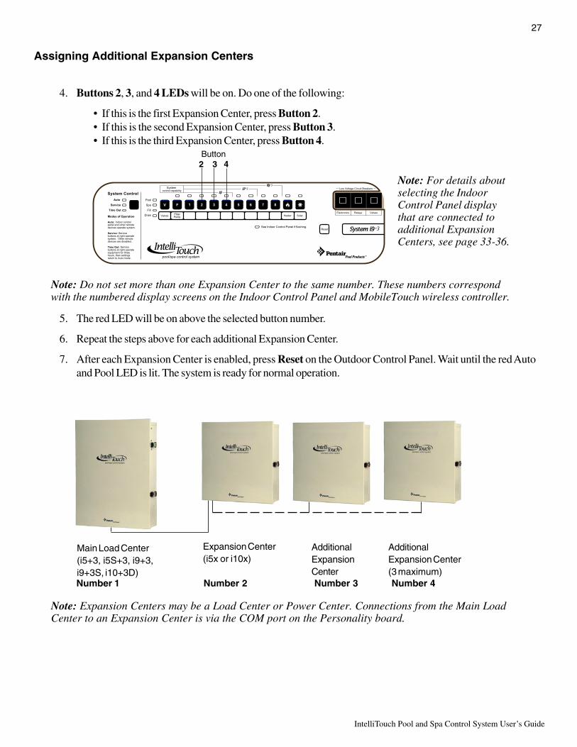
27
IntelliTouch Pool and Spa Control System User’s Guide
Assigning Additional Expansion Centers
4. Buttons 2, 3, and 4 LEDs will be on. Do one of the following:
• If this is the first Expansion Center, press Button 2.• If this is the second Expansion Center, press Button 3.• If this is the third Expansion Center, press Button 4.
Note: Do not set more than one Expansion Center to the same number. These numbers correspondwith the numbered display screens on the Indoor Control Panel and MobileTouch wireless controller.
5. The red LED will be on above the selected button number.
6. Repeat the steps above for each additional Expansion Center.
7. After each Expansion Center is enabled, press Reset on the Outdoor Control Panel. Wait until the red Autoand Pool LED is lit. The system is ready for normal operation.
AdditionalExpansion Center(3 maximum)
Main Load Center(i5+3, i5S+3, i9+3,i9+3S, i10+3D)
Expansion Center(i5x or i10x)
AdditionalExpansionCenter
Number 1 Number 2 Number 3 Number 4
Note: Expansion Centers may be a Load Center or Power Center. Connections from the Main LoadCenter to an Expansion Center is via the COM port on the Personality board.
Button2 3 4
Note: For details aboutselecting the IndoorControl Panel displaythat are connected toadditional ExpansionCenters, see page 33-36.
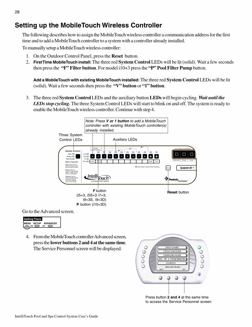
IntelliTouch Pool and Spa Control System User’s Guide
28
Setting up the MobileTouch Wireless ControllerThe following describes how to assign the MobileTouch wireless controller a communication address for the firsttime and to add a MobileTouch controller to a system with a controller already installed.
To manually setup a MobileTouch wireless controller:
1. On the Outdoor Control Panel, press the Reset button.2. First Time MobileTouch install: The three red System Control LEDs will be lit (solid). Wait a few seconds
then press the “F” Filter button. For model i10+3 press the “P” Pool Filter Pump button.
Add a MobileTouch with existing MobileTouch installed: The three red System Control LEDs will be lit(solid). Wait a few seconds then press the “V” button or “1” button.
3. The three red System Control LEDs and the auxiliary button LEDs will begin cycling. Wait until theLEDs stop cycling. The three System Control LEDs will start to blink on and off. The system is ready toenable the MobileTouch wireless controller. Continue with step 4.
Go to the Advanced screen.
4. From the MobileTouch controller Advanced screen,press the lower buttons 2 and 4 at the same time.The Service Personnel screen will be displayed.
MENU SETUP ADVANCED
Getting There
Press button 2 and 4 at the same timeto access the Service Personnel screen
Three SystemControl LEDs Auxiliary LEDs
Reset buttonF button(i5+3, i5S+3 i7+3,
i9+3S, i9+3D)P button (i10+3D)
Note: Press V or 1 button to add a MobileTouchcontroller with existing MobileTouch controller(s)already installed.

29
IntelliTouch Pool and Spa Control System User’s Guide
Setting up the MobileTouch Wireless Controller (Continued)
5. Press the button next to LOCK ON ADDRESS to access the next screen.
6. Press the button next to LOCK ON ADDRESS to assign a unique frequency for the MobileTouch controllerto avoid inference from other wireless devices within range of the MobileTouch transceiver.
7. After selecting “Lock On Address” the MobileTouch controller is now ready to operate the IntelliTouchsystem. The “Service Personnel” screen will be displayed.
8. Press Exit to return to the main screen or proceed with Step 9 if you are adding another MobileTouchcontroller while the IntelliTouch outdoor control panel LEDs are flashing.
9. To add another MobileTouch controller at this time, repeat Steps 4 through 8 for each controller, if not,continue with Step 10.
10. Return the Load Center or Power Center. The System Control LEDs will be flashing. Press the Reset button.When the “Auto” LED is illuminated the process is complete and the system is ready for operation.

IntelliTouch Pool and Spa Control System User’s Guide
30
Adding an iS10 Spa-Side Remote ControllerUp to four iS10 Spa-Side remote controllers can be installed to allow each iS10 to operate different functionsor to the same functions at different locations. Each iS10 can be assigned as number 1, 2, 3, or 4. If a differentnumber is not assigned to each installed iS10, then all iS10’s are assigned as number iS1. This is useful if youwish to have the same functions available at different iS10 locations.
The following steps describe how to manually assign each iS10 a number 2, 3, or 4 as required.
Note: If the first iS10 was installed with the main Load Center or Power Center, it will automatically beassigned as number IS1. Other additional iS10 remotes need to be manually assigned.
To assign additional iS10 remotes as iS2, iS3, or iS4:
1. On the IntelliTouch Outdoor Control Panel, press the Reset button, then press the 1 button. The three (3)System Control LEDs will start flashing.
2. On the iS10 remote, press the bottom part of the “peanut shaped” toggle switch and the 1 button at the sametime (while the Outdoor Control Panel LEDs are flashing).
3. SHA will be displayed on the iS10 temperature display. The four red iS10 LEDs adjacent to the in-linebuttons will be lit.
4. Assign the iS10 to one of the following:• If this is the second iS10, press button #2. The temperature display reads IS2.• If this is the third iS10, press button #3. The temperature display reads IS3.• If this is the fourth iS10, press button #4. The temperature display reads IS4.
5. The two iS10 red toggle switch LEDs will start to flash.6. On the Outdoor Control Panel, press the Reset button. The iS10 LEDs will stop flashing. Repeat steps 1-4
for additional iS10 remotes. To configure the iS10 buttons, see page 78.
Note: To disable or enable the iS10 Spa-Side Remote from the Indoor Control Panel orMobileTouch wireless control panel, refer to “Disable/Enable iS10 and iS4 Spa-Side Remote,” onpage 80.
3 LEDs (Auto,
Service andTime Out)
Reset buttonButton #1
Main Outdoor Control Panel and iS10 Spa-Side remote controller
Press Toggle switch and button #1 at the same time

31
IntelliTouch Pool and Spa Control System User’s Guide
Prepare the System for OperationIf there are more than one Indoor Control Panel, you only need to configure one of the panels. Other IndoorControl Panels will be configured using these same settings. Before you start, make sure you have:
• Pen and paper• Write in the circuit names in the provides labels under each button on the Outdoor Control Panel and the
Circuit ID label worksheet (see page 86-91). Use a permanent marker, or other permanent means of labeling.• If you are setting up a large system that covers a large area, ask your assistant to visually inspect the
equipment while you test the circuits from the Outdoor Control Panel.
Note: To reset the system to the factory defaults, see “Erasing Outdoor Control Panel Memory (FactoryDefault),” on page 94.
Checking the Main Load CenterUse the following steps to check that the system is working correctly.
1. Switch on the AC electrical power at the house breaker.
2. Switch on the Load Center or Power Center. You may need to switch on the breakers on the Load Center.
3. Wait for the following:
· On the Outdoor Control Panel check that the red Auto LED is on.· The LED next to See Indoor Control Panel if Flashing is not on.
4. Press the Service button to place the Load Center or Power Center in Service Mode for testing.
Note: for i5+3, i7+3, or i9+3 systems, go to step 5. If you are working with the i5S+3, i9+3S, or i10+3Dsystems, skip step 5 and go to step 6. The IntelliTouch system model ID is located on the front of the IndoorControl Panel below the low voltage circuit breakers.
5. Press the Valves (V) button. Step through all four valve positions: Pool, Spa, Fill, Drain. Make sure thevalves rotate to the correct position and the water is moving in the correct direction for each position. Ifnecessary, flip the actuator toggle switch to change the direction of the water. After setting the valves and thesystem is in “Auto” mode, do not change the toggle switches.
6. Press the Filter Pump (F) button. Make sure the filter pump turns on correctly. If the pump has two speeds:Press the button one time to run the pump in low speed. Press the button again to run the pump in high speed.Press the button again to switch the pump off. A Two-Speed pump has to be configured from theEQUIPMENT screen.
7. Press each of the AUX buttons. Notice which button turns on which equipment. You may need to walk theproperty to find what each button turns on.
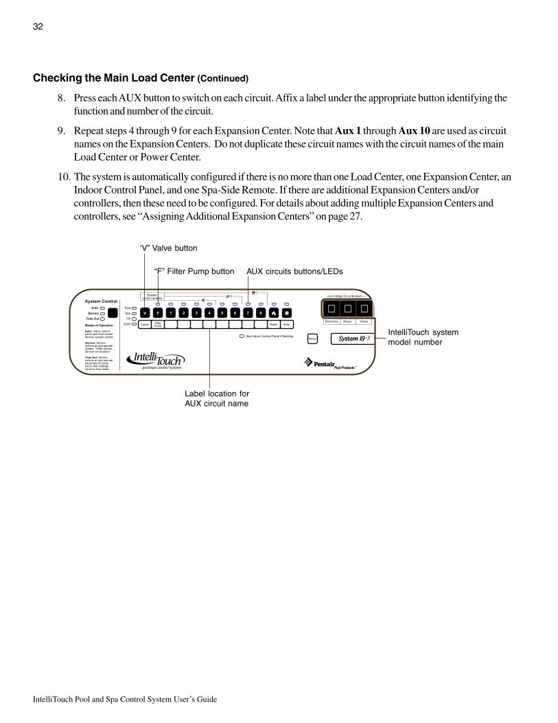
IntelliTouch Pool and Spa Control System User’s Guide
32
Checking the Main Load Center (Continued)
8. Press each AUX button to switch on each circuit. Affix a label under the appropriate button identifying thefunction and number of the circuit.
9. Repeat steps 4 through 9 for each Expansion Center. Note that Aux 1 through Aux 10 are used as circuitnames on the Expansion Centers. Do not duplicate these circuit names with the circuit names of the mainLoad Center or Power Center.
10. The system is automatically configured if there is no more than one Load Center, one Expansion Center, anIndoor Control Panel, and one Spa-Side Remote. If there are additional Expansion Centers and/orcontrollers, then these need to be configured. For details about adding multiple Expansion Centers andcontrollers, see “Assigning Additional Expansion Centers” on page 27.
‘V” Valve button
“F” Filter Pump button
IntelliTouch systemmodel number
Label location forAUX circuit name
AUX circuits buttons/LEDs

33
IntelliTouch Pool and Spa Control System User’s Guide
Setting up the IntelliTouch System using the Indoor Control Panel orMobileTouch
The following describes how to configure and set up the IntelliTouch system using the Indoor Control Panel orMobileTouch wireless control panel.
The Preference Screen OptionsFrom the Preference screen you can change various screen options.
To change the screen settings go to the Preferences screen.
1. To change the display backlight: Press the top left orright side button to select the following options: OFF IN 5MIN, BLANK IN 5 MIN, and ALWAYS ON.
2. To change the display contrast: Press the left button todecrease the display contrast level (lighter). Press the rightside button to increase the display contrast level (darker).
3. To change the brightness of the LED lights: Press eitherthe left or right side button to set the LED brightness level to100%, 75%, 50%, or 25%.
4. To change the display backlight brightness: Press eitherthe left or right side button to set the Backlight Brightnesslevel to 100%, 75%, 50%, or 25%.
5. To turn the button beeper sound off/on: Press the buttonnext to User Interface. From the next screen, press thebutton next to Beeper Level to OFF. To switch ON thesound, select HIGH. Press the Back button when finished.
Note about Key Repeat: It is recommended to leave theKey Repeat Delay and Rate set to the factory defaultsetting (1/2 and 15 PS). The Key Repeat Delay adjuststhe amount of time a key/button has to be held downbefore it starts auto-repeating. Key Repeat Rate adjuststhe number of times per second (5, 10, 15, or 20 keyrepeats per second) the key/button repeats once it is helddown.
6. When finished, to save the settings press the Exit button toreturn to the main screen.
15 PS

IntelliTouch Pool and Spa Control System User’s Guide
34
Set the System ClockIt’s important to set the IntelliTouch system clock to the current time and date to ensure all automatic poolfunctions to work correctly.
To set the system clock, go to the Clock screen.
1. Use the left or right side buttons to set each of the clocksettings.
2. Setting Daylight Savings:Set to Auto if you are in an area that observes DaylightSavings. Set to Manual if you are in an area that doesnot observe Daylight Savings.
3. Setting clock accuracy offset: To change the clockaccuracy offset by seconds, press the right-side button toincrease the offset and the left-side button to decreasethe value. The offset value can be set from-300 to +300 seconds. If the internal system clock timeis displaying ahead or behind the current time, use thisthe offset value to correct the clock.
4. Press the Set button to save the settings.
5. Press the Exit button to return to the main screen.
Assigning Circuit Names (for Display 1, 2, 3, and 4)There can be up to four (4) Display screens that can be accessed, depending on the number of expansion LoadCenters or Power Centers (see page 27 for more information). Assigning the system circuit names allows you toidentify equipment from the Indoor Control Panel or MobileTouch wireless control panel. There are almost 100preset equipment names to choose from (see page 37) to identify pool, spa and other related equipment. Thereare also 20 user-definable names to use for custom equipment if the preset circuit names are not suitable.Customizing names can also help identify unique system equipment. Assigning a custom circuit name to multiplecircuits which then can be switched on or off from one button on the Indoor Control Panel or MobileTouchcontrol panel. This method is called creating a MACRO (see page 77). For more information, refer to “CreatingCustom Names for Auxiliary Circuits,” page 38.
Note: The top left and right circuit names (SPA and POOL) on the main display DISPLAY #1) shouldnot be changed. These circuits have special reserved functionality that cannot be changed. The defaultcircuits may be given any name but always perform in the same manner. Be careful not to duplicatecircuit names with these circuits. These circuits may also be used to activate 2-speed pumps to highspeed, turn additional valves, etc.
A SUN 12
MENU SETUP CLOCK
Getting There

35
IntelliTouch Pool and Spa Control System User’s Guide
Selecting DISPLAY Screen 1, 2, 3, or 4The auxiliary circuits that control the pool and spa equipment can be accessed from the “Display” screen on theIndoor Control Panel or MobileTouch wireless control panel. Selecting the button next to Display 1, 2, 3, or 4displays the screen with circuits belonging to that particular expansion Load Center or Power Center. “FeatureCircuits” can also be assigned from this screen. For more information about “Feature Circuits,” see page 76.
To assign circuit names for a specific display screen:
MENU SETUP CIRCUIT NAMES ASSIGN CIRCUIT NAMES DISPLAYADVANCED
Getting There
Display #1 - This screen shows circuit names for the filter pump, pooland spa modes, and all high voltage auxiliary circuits connected to themain Load Center or Power Center.
Display #2 - This screen shows circuit names for the additional auxiliarycircuits connected to the first expansion center (Load Center or PowerCenter).
Display #3 - This screen shows circuit names for the additional auxiliarycircuits connected to the second expansion center (Load Center orPower Center)
Display #4 - This screen shows circuit names for the additional auxiliarycircuits connected to the third expansion center (Load Center or PowerCenter).
BACK EXIT
DISPLAY 1
DISPLAY 2
DISPLAY 3
DISPLAY 4
FEATURE
Assigning Circuit NamesIn order to identify the equipment connected to the auxiliary circuits (SPA, AUX 1, AUX 2) in the Load Center,you need to assign equipment names to the corresponding auxiliary circuits in the Indoor Control Panel.
Using the written list of circuit names (button 1, button 2, etc.) made while setting up the system. Match the labelname that was placed under each button (1, 2, etc.) on the Load Center Outdoor Control Panel with theselected circuit name that will be displayed on the “Main Display” screen.
Choose a circuit name from the preset list of names (see page 37) forequipment connected to the auxiliary relays installed in the main LoadCenter. There are also 20 user-definable names to use for other pool andspa related equipment if the preset circuit names are not suitable(see page 38).
To assign circuit names for the MAIN SCREEN:
1. Select the button next to Display #1 (Main Display screen, see page7). These are the circuit names that will be displayed on the MainScreen. Note: If there is an expansion Load Center or PowerCenter installed, select the appropriate Display #2, #3, or #4associated with that expansion Load Center or Power Center.
2. From the Main Display screen, press the button next to AUX 1.A small arrow pointing to AUX 1 is displayed.
3. Use the Up and Down buttons at the bottom of the screen to scroll through the alphabetical list of presetequipment names. Choose the equipment name that matches the label name for button number 1 on the LoadCenter Outdoor Control Panel.
BACK
MENU/SETUP/ADV/AUX/NAME/DISP #1
SAVE DOWN UP
FLOOR CLNR
FOUNTAIN
BBQ LIGHT
EDGE PUMP
CLEANER
BACK LIGHT
WATER FALL
LIONS HEAD
Down/Up button

IntelliTouch Pool and Spa Control System User’s Guide
36
4. Continue to name other auxiliary circuits (AUX2,AUX3, etc.): After selecting the equipment name youwant to use for AUX 1, press the button next to theAUX 2 and choose a circuit name. The small arrowindicates which circuit is selected for naming.
5. Repeat the process to assign the other equipment tocircuits on this screen.
6. When you have finished assigning equipment circuitnames, press the Save button.
7. Press the Exit button to return to the Main screen.
Selecting the Display ScreensThere are thee (3) screens to view and setup auxiliary circuits:
• Main Screen: Displays assigned auxiliary (AUX 1, AUX 2, etc.) circuit names. An M icon located inthe middle lower part of the screen indicates that the “Main Screen” is selected.
• Display #1: Displays the auxiliary (AUX 1, AUX 2, etc.) circuits connected to the main Load Center.The number 1 icon located in the middle lower part of the screen indicates that circuits for Display#1 is selected.
• Display #2, #3, or #4: Displays the auxiliary circuits connected to additional expansion Load orPower Centers. The number 2 icon located in the middle lower part of the screen indicates thatcircuits for Display #2 is selected.
• Feature: Displays auxiliary circuits configured as “Feature” circuits. The F icon located in themiddle lower part of the screen indicates that Feature circuits screen is selected.
To select the Display screens, press the lower right DISPLAY button to toggle through each of the screens. Formore information, see page 7.
1
MENU HEAT LIGHTS DISPLAY
EDGE PUMPALL LIGHTS
WATER FALL
CLEANERS
F MON 4:32AMAIR TEMP 92˚
Main screen Display #1, #2, #3, or #4 screen Feature circuits screen
Display button
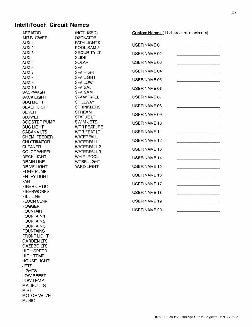
37
IntelliTouch Pool and Spa Control System User’s Guide
AERATORAIR BLOWERAUX 1AUX 2AUX 3AUX 4AUX 5AUX 6AUX 7AUX 8AUX 9AUX 10BACKWASHBACK LIGHTBBQ LIGHTBEACH LIGHTBENCHBLOWERBOOSTER PUMPBUG LIGHTCABANA LTSCHEM. FEEDERCHLORINATORCLEANERCOLOR WHEELDECK LIGHTDRAIN LINEDRIVE LIGHTEDGE PUMPENTRY LIGHTFANFIBER OPTICFIBERWORKSFILL LINEFLOOR CLNRFOGGERFOUNTAINFOUNTAIN 1FOUNTAIN 2FOUNTAIN 3FOUNTAINSFRONT LIGHTGARDEN LTSGAZEBO LTSHIGH SPEEDHIGH TEMPHOUSE LIGHTJETSLIGHTSLOW SPEEDLOW TEMPMALIBU LTSMISTMOTOR VALVEMUSIC
IntelliTouch Circuit NamesCustom Names (11 characters maximum)
USER NAME 01 ____________________
USER NAME 02 ____________________
USER NAME 03 ____________________
USER NAME 04 ____________________
USER NAME 05 ____________________
USER NAME 06 ____________________
USER NAME 07 ____________________
USER NAME 08 ____________________
USER NAME 09 ____________________
USER NAME 10 ____________________
USER NAME 11 ____________________
USER NAME 12 ____________________
USER NAME 13 ____________________
USER NAME 14 ____________________
USER NAME 15 ____________________
USER NAME 16 ____________________
USER NAME 17 ____________________
USER NAME 18 ____________________
USER NAME 19 ____________________
USER NAME 20 ____________________
(NOT USED)OZONATORPATH LIGHTSPOOL SAM 3SECURITY LTSLIDESOLARSPASPA HIGHSPA LIGHTSPA LOWSPA SALSPA SAMSPA WTRFLLSPILLWAYSPRINKLERSSTREAMSTATUE LTSWIM JETSWTR FEATUREWTR FEAT LTWATERFALLWATERFALL 1WATERFALL 2WATERFALL 3WHIRLPOOLWTRFL LGHTYARD LIGHT
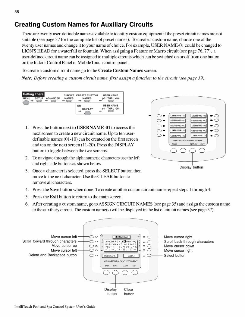
IntelliTouch Pool and Spa Control System User’s Guide
38
Creating Custom Names for Auxiliary CircuitsThere are twenty user-definable names available to identify custom equipment if the preset circuit names are notsuitable (see page 37 for the complete list of preset names). To create a custom name, choose one of thetwenty user names and change it to your name of choice. For example, USER NAME-01 could be changed toLION'S HEAD for a waterfall or fountain. When assigning a Feature or Macro circuit (see page 76, 77), auser-defined circuit name can be assigned to multiple circuits which can be switched on or off from one buttonon the Indoor Control Panel or MobileTouch control panel.
To create a custom circuit name go to the Create Custom Names screen.
Note: Before creating a custom circuit name, first assign a function to the circuit (see page 39).
1. Press the button next to USERNAME-01 to access thenext screen to create a new circuit name. Up to ten user-definable names (01-10) can be created on the first screenand ten on the next screen (11-20). Press the DISPLAYbutton to toggle between the two screens.
2. To navigate through the alphanumeric characters use the leftand right side buttons as shown below.
3. Once a character is selected, press the SELECT button thenmove to the next character. Use the CLEAR button toremove all characters.
4. Press the Save button when done. To create another custom circuit name repeat steps 1 through 4.
5. Press the Exit button to return to the main screen.
6. After creating a custom name, go to ASSIGN CIRCUIT NAMES (see page 35) and assign the custom nameto the auxiliary circuit. The custom name(s) will be displayed in the list of circuit names (see page 37).
N
Displaybutton
Delete and Backspace button Select buttonMove cursor rightMove cursor left
Move cursor up Move cursor downScroll forward through characters Scroll back through characters
Move cursor left Move cursor right
Clearbutton
USERNAME - 01
USERNAME - 01
USERNAME - 01
USERNAME - 01
USERNAME - 01
USERNAME - 01
USERNAME - 01
USERNAME - 01
USERNAME - 01
USERNAME - 01
MENU/SETUP/ADV/CUSTOM/SELECT
BACK DISPLAY EXIT
Display button

39
IntelliTouch Pool and Spa Control System User’s Guide
Assign Circuit Functions and Freeze ProtectionAssigning a function to an auxiliary circuit allows certain type of equipment to operate in a specific way. Forexample, when setting up an automatic pool cleaner pump, you would assign the circuit function to MASTERCLEANER. With this "Cleaner" logic, when the circuit is switched on the cleaner pump would force the filterpump on, and start the cleaner pump after a delay of five (5) minutes. The cleaner pump would automaticallyshut off whenever the spa and solar is switched on with the cleaner pump (after a delay of five (5) minutes) ifenergy from the solar is required.
Freeze ProtectionFreeze protection switches a circuit on if the outdoor air temperature sensor detects the temperature is gettingclose to freezing (below 36° F (2 ° C). The system switches on all circuits that have been assigned freezeprotection, and switches on the filter pump to circulate water throughout the system for 15 minutes to stop thepipes from freezing. This is especially important for a pool and spa combination (dual body shared equipment).If freeze protection is set to both the spa and pool circuits, the filter pump switches on and the pool and spavalves alternate every 15 minutes to keep the water moving through both the pool and spa. This processcontinues until the freeze condition is over.
Assigning a function and freeze protection to a circuit
To assign a function to an auxiliary circuit and to add circuit freeze protection:
1. Press the button next to the circuit name that requires a function.
2. Press the lower DISPLAY button to view the Feature circuits.Select the Feature circuit name to assign a function to it. Use thisbutton to toggle between the Feature circuit screen and the Circuitscreen.
MENU SETUP ADVANCED CIRCUIT FUNCTIONS SELECT DESIRED CIRCUITSELECT DESIRED SCREEN DISPLAY 1,2,3,4 or F
This Button appears onlywhen you have FEATUREcircuits or multiple DISPLAYS.
Getting There
AUX 2
AUX 4
AUX 7
AUX 6
AUX 5
AUX 8
BACK DISPLAY EXIT
FLOOR CLNR
FOUNTAIN
MENU/SETUP/ADV/FUNCTION/SELECT1
MENU HEAT LIGHTS DISPLAY
EDGE PUMPALL LIGHTS
WATER FALL
CLEANERS
F MON 4:32AMAIR TEMP 92˚

IntelliTouch Pool and Spa Control System User’s Guide
40
Assigning a function and freeze protection to a circuit (Continued)
To assign a function to an auxiliary circuit and to add circuit freeze protection:
1. Press the top right side button next to the displayed circuit names (i.e., CLEANER). The circuit displayed isselected from the previous screen.
2. Use the left and right side button next to PREV and NEXT to select the function for this circuit. For example,circuit function MASTER CLEANER selects the type of logic needed for a cleaner circuit. To assign a lightfunction, select IntelliBrite, SAM Light or SAL Light. For the complete list of circuit functions, see SpecialFunctions for Circuits, on page 41. Note: When using “pressure cleaners” assign the circuit to “MasterCleaner.”
3. Use the left and right side button next to ON WITH FREEZE to select YES for freeze protection. This willactivate the circuit if the air temperature drops below 36° F (2° C). Select NO for no freeze protection.Note: Freeze protection is automatically enabled for SPA, POOL, HI-TEMP, and LOW-TEMP circuits.
4. Press the SAVE button when finished.
5. Press the BACK button to return to the Circuits screen and repeat steps 1 through 4 to assign functions toother circuits.
6. Press EXIT button to return to the Main screen.
MENU/SETUP/ADV/FUNC/CLEANER
Note: Spa operation and freeze protect time:Using the “Spa Freeze Override” feature, thefreeze protect default time of 30 minutes canbe increase from 30 minutes to 240 minutesmaximum. For more information, see page 71.
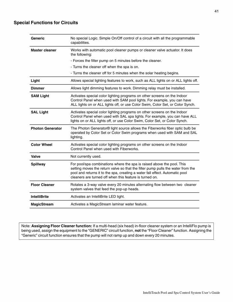
41
IntelliTouch Pool and Spa Control System User’s Guide
Special Functions for Circuits
cireneG elbammargorpehtllahtiwtiucricafolortnocffO/nOelpmiS.cigoLlaicepsoN.seitilibapac
renaelcretsaM seodtI.rotautcaevlavrenaelcrospmuprenaelcloopcitamotuahtiwskroW:gniwollofeht
.renaelcehterofebsetunim5nopmupretlifehtsecroF-
.nosiapsehtnehwfforenaelcehtsnruT-
.snigebgnitaehralosehtnehwsetunim5roffforenaelcehtsnruT-
thgiL .ffosthgilLLAronosthgilLLAsahcus,krowotserutaefgnithgillaicepsswollA
remmiD .dellatsniebtsumyalergnimmiD.krowotserutaefgnimmidthgilswollA
thgiLMAS roodnIehtnosneercsrehtonosmargorpgnithgilroloclaicepssetavitcAevahnacuoy,elpmaxeroF.sthgilloopMAShtiwdesunehwlenaPlortnoC
.hcnySroloCro,teSroloC,miwSroloCesuro,ffosthgilLLAronosthgilLLA
thgiLLAS roodnIehtnosneercsrehtonosmargorpgnithgilroloclaicepssetavitcAhtiwdesunehwlenaPlortnoC LAS evahnacuoy,elpmaxeroF.sthgilaps LLA
ro,ffosthgilLLAronosthgil .hcnySroloCro,teSroloC,miwSroloCesu
rotareneGnotohP ebblubcitporebifskrowrebiFehtswollaecruosthgil®rotareneGnotohPehTLASdnaMAShtiwdesunehwsmargorpmiwSroloCroteSroloCybdetarepo
.gnithgil
leehWroloC roodnIehtnosneercsrehtonosmargorpgnithgilroloclaicepssetavitcA.skrowrebiFhtiwdesunehwlenaPlortnoC
evlaV .desuyltnerructoN
yawllipS sihT.loopehtevobadesiarsiapsehterehwsnoitanibmocaps/looproFehtmorfretawehtslluppmupretlifehttahtosevlavnruterehtsevomgnittes
loopcitamotuA.tceffellafretawagnitaerc,apsehtottisnruterdnaloop.nodenrutsierutaefsihtnehwffodenruterasrenaelc
renaelCroolF renaelcowtneewtebwolfgnitanretlasetunim02yreveevlavyaw-3asetatoR.sdaehpu-popehtdeeftahtsevlavmetsys
etirBilletnI .thgilDELetirBilletnInasetavitcA
maertScigaM .erutaefretawranimalmaertScigaMasetavitcA
Note: Assigning Floor Cleaner function: If a multi-head (six head) in-floor cleaner system or an IntelliFlo pump isbeing used, assign the equipment to the “GENERIC” circuit function, not the “Floor Cleaner” function. Assigning the“Generic” circuit function ensures that the pump will not ramp up and down every 20 minutes.

IntelliTouch Pool and Spa Control System User’s Guide
42
Setting up Lighting Options (Color Swim and Color Set) - Requires use of at
least two SAm and/or SAL and/or Fiberworks Lighting products controlled by separate AUX circuits
There can be up to 12 light circuits on the main Lights screen. From this screen you can activate the “ColorSwim” and Color Set” special lighting features. These special features each must have their own relay andseparate circuits.
Color Swim and Color SetAlthough the same screen is used to program the Color Swim and Color Set features, these two special lightingeffects operate independently of each other. It may take up to a minute or more for Color Swim or Color Set tooperate as programmed, depending on what kind of light you are activating and what state it was in when theeffect was activated.
• Color Swim - Allows any combination of up to 12 SAm, SAL, and/or FIBERworks lighting circuits to bepreset to transition through colors in sequence, giving the appearance of the colors swimming across thewater. The delay in sequencing each light can be adjusted to customize the display for your pool. This featurerequires the use of at least two SAm, SAL, and/or FIBERworks lighting products controlled by separateAUX circuits and relays.
• Color Set - Allows any combination of up to 12 SAm, SAL, and/or FIBERworks lighting circuits to bepreset to specific colors. For example, you can set the colors for red, white, and blue, or red and green.
• Sync - Switches all color changing lights ON to synchronize their colors.
• Smart Start (SS_Yes and SS_No) - The Smart Start feature allows light circuits that are programmed to switchon at a specific time, automatically begin changing their colors. For more information see page 15.
Setting up Color Swim and Color Set with SAm, SAL, or FIBERworks
Both the Color Swim and Color Set feature can be configured and operated from the Lights screen, butoperate independently of each other. Depending on what kind of light is being switched on and what state it wasin when the lighting effect was activated, it may take up to a minute or more for Color Swim or Color Set tooperate as programmed. The Color Swim feature creates the illusion of bands of colors moving through thewater. This is accomplished by switching on each light with a specific color in a specified order at different timeintervals. The order and time delay between lights can be mixed and matched to create many different effects.For example, colors moving left to right, one body of water to another, from the middle outward, etc.
To assign light circuits to the Lights screen:
Before Starting: Be sure the auxiliary circuits that control the lights have been assigned names. Then verify thatSAm and SAL lights have been assigned in the “CIRCUIT FUNCTIONS” as SAM and SAL lights. IfFIBERworks lighting is being used, it also has to be set up as a PHOTON GENERATOR for the circuitcontrolling the light bulb, and COLOR WHEEL for the circuit controlling the color wheel (see page 41).
Setting up Color Swim and Color Set lights
The following steps (see next page) describes how to setup an AUX circuit to control the Color Swim andColor Set lighting features. The first step is to assign the circuit light function an auxiliary relay circuit (AUX 1),then assign the circuit name for that light circuit. The light circuit name will appear on the main screen. Each light(SAM or SAL) must also be assigned a circuit function. If the circuit function has been assigned, start at Step 5(see next page).
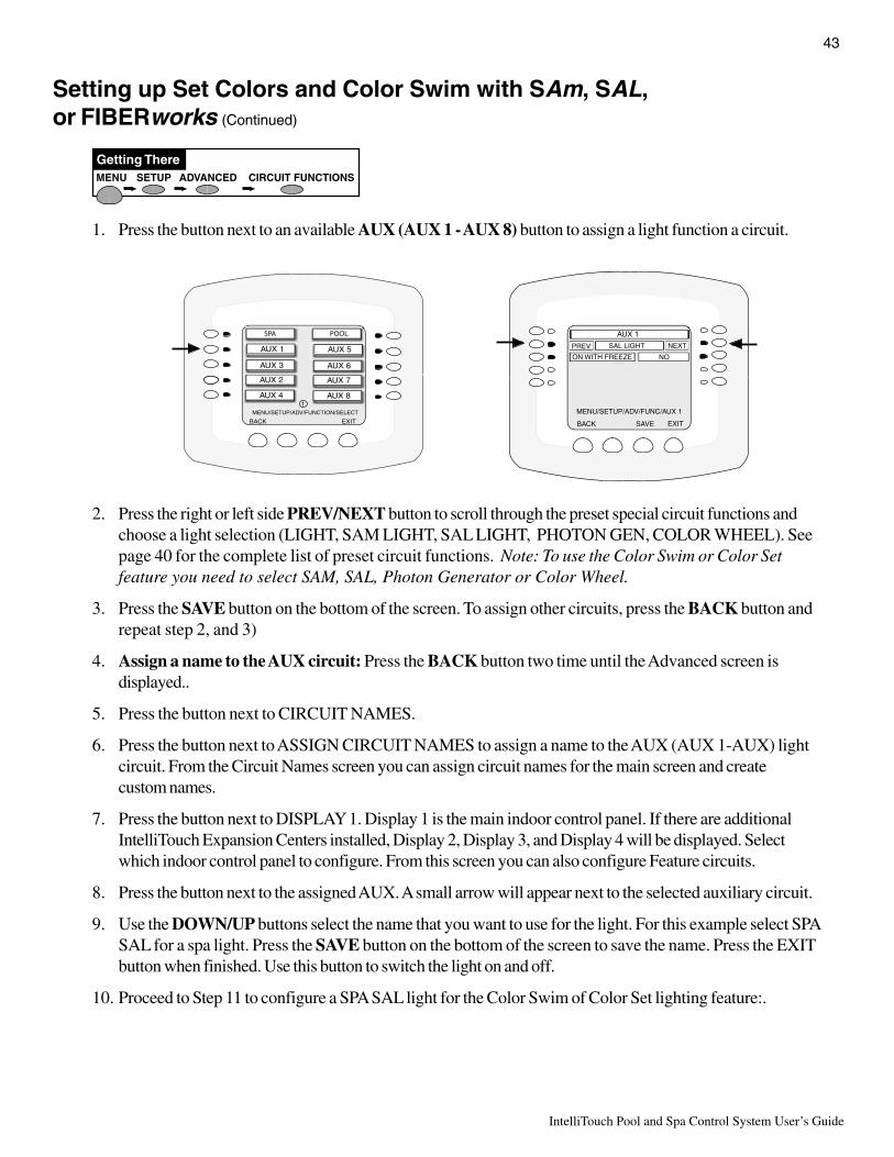
43
IntelliTouch Pool and Spa Control System User’s Guide
Setting up Set Colors and Color Swim with SAm, SAL,or FIBERworks (Continued)
MENU SETUP CIRCUIT FUNCTIONSADVANCED
Getting There
1. Press the button next to an available AUX (AUX 1 - AUX 8) button to assign a light function a circuit.
2. Press the right or left side PREV/NEXT button to scroll through the preset special circuit functions andchoose a light selection (LIGHT, SAM LIGHT, SAL LIGHT, PHOTON GEN, COLOR WHEEL). Seepage 40 for the complete list of preset circuit functions. Note: To use the Color Swim or Color Setfeature you need to select SAM, SAL, Photon Generator or Color Wheel.
3. Press the SAVE button on the bottom of the screen. To assign other circuits, press the BACK button andrepeat step 2, and 3)
4. Assign a name to the AUX circuit: Press the BACK button two time until the Advanced screen isdisplayed..
5. Press the button next to CIRCUIT NAMES.
6. Press the button next to ASSIGN CIRCUIT NAMES to assign a name to the AUX (AUX 1-AUX) lightcircuit. From the Circuit Names screen you can assign circuit names for the main screen and createcustom names.
7. Press the button next to DISPLAY 1. Display 1 is the main indoor control panel. If there are additionalIntelliTouch Expansion Centers installed, Display 2, Display 3, and Display 4 will be displayed. Selectwhich indoor control panel to configure. From this screen you can also configure Feature circuits.
8. Press the button next to the assigned AUX. A small arrow will appear next to the selected auxiliary circuit.
9. Use the DOWN/UP buttons select the name that you want to use for the light. For this example select SPASAL for a spa light. Press the SAVE button on the bottom of the screen to save the name. Press the EXITbutton when finished. Use this button to switch the light on and off.
10. Proceed to Step 11 to configure a SPA SAL light for the Color Swim of Color Set lighting feature:.
MENU/SETUP/ADV/FUNC/AUX 1
EXITBACK
NO
NEXT
AUX 1
PREV
ON WITH FREEZE
SAVE
SAL LIGHT
AUX 2
AUX 3
AUX 1
AUX 4
AUX 7
AUX 6
AUX 5
AUX 8
MENU/SETUP/ADV/FUNCTION/SELECT
BACK EXIT
1

IntelliTouch Pool and Spa Control System User’s Guide
44
LIGHTS CONFIGURE NEXT TO "NONE"PRESS BUTTON
Getting There
To configure the SPA SAL light for the Color Swim of Color Set lighting feature:
11. From the main screen, press the Lights button on the bottom of the screen.12. Press the right or left side button next to CONFIGURE.
13. Press the button next to NONE to assign a light circuit to the selected button. Light names can be setup todisplay on the left side for “Spa” features and on the right side for the “Pool” features.
Available lightcircuit for “SPA”
LIGHTS/CONFIG-SELECTION
EXITBACK
NONE
POOL SAM 1POOL LIGHT
NEXT GROUP
SPA SAL
NONE
NONE
Press this button to configure “Pool Sam 1” light
View/configure next sixlight circuits
Available light circuit for “POOL”
LIGHTS
ALL OFF SYNCSAVE ALL ON
CONFIGURENEXT GROUP
COLOR SET COLOR SWIM
Lights screen

45
IntelliTouch Pool and Spa Control System User’s Guide
Setting up Set Colors and Color Swim with SAm, SAL,or FIBERworks (Continued)
14. Press the top left or right side button to scroll through the available light circuits which can be used for theColor Set and Color Swim feature. Stop at the circuit name you wish to use. The displayed circuit namesselections are circuit names that were previously assigned (when assigning a circuit function). If there areno circuits available for selection, refer to “Assigning Circuit Names, ” on page 3, and “Assigning CircuitFunctions and Freeze Protection” on pages 39 for more information.
15. Using the Color Set feature: Press the second button down from the top to scroll through the colorchoices. Select the color of your choice. The selections are, White, Light Green, Cyan, Blue, Lavender,Magenta and Light Magenta.
16. Set Light Position: Press the third button down from the top to set the position of the first light in thesequence. Position 1 will lead all the other lights in the color changing sequence. Position 2 followsPosition 1 and so on. There are 12 position to choose from. More than one light may be assigned to thesame position number so that their colors may be synchronized. For example, to make the colors swimright to left, make your right most light POSITION 1. You may need to go back to Step 1 and scrollthrough your lights to find the right most light, and set it as POSITION 1.
17. Using the Color Swim feature: Press the forth button down from the top to set the time delay betweenthis light and the previous position. Use a higher delay time for lights spread further apart. Try five secondsfor all lights and observe the effect. Use different time settings to achieve unique lighting moods andeffects.
18. Press the Save button to save the current setting for the first light.The previous “CONFIGURE-SELECTION” screen isdisplayed. Continue to setup the light circuits. Press the buttonnext to “NEXT GROUP” to access the next screen for anadditional six circuits. Repeat step 1 through 5 to set the light forPOSITION 2 for Color Swim, and a new color choice for ColorSet. Press Save. Repeat this process until all desired lights haveset colors, positions and delays.
19. Press Back to view the Lights screen. “SPA SAL” on and offswitch is now assigned to the AUX 1 button.
LIGHTS
ALL OFF SYNCSAVE ALL ON
CONFIGURENEXT GROUP
SPA SAL
COLOR SET COLOR SWIM
LIGHTS/CONFIG/SPA SAL
PREV NEXT
PREV
PREV
PREV
NEXT
NEXT
NEXTSPA SAL
WHITE
1ST POSITION
DELAY 5 SECS
SAVE EXIT
Select the light circuitSelect the color
Select the light positionColor Swim: Set the delay time
between lights
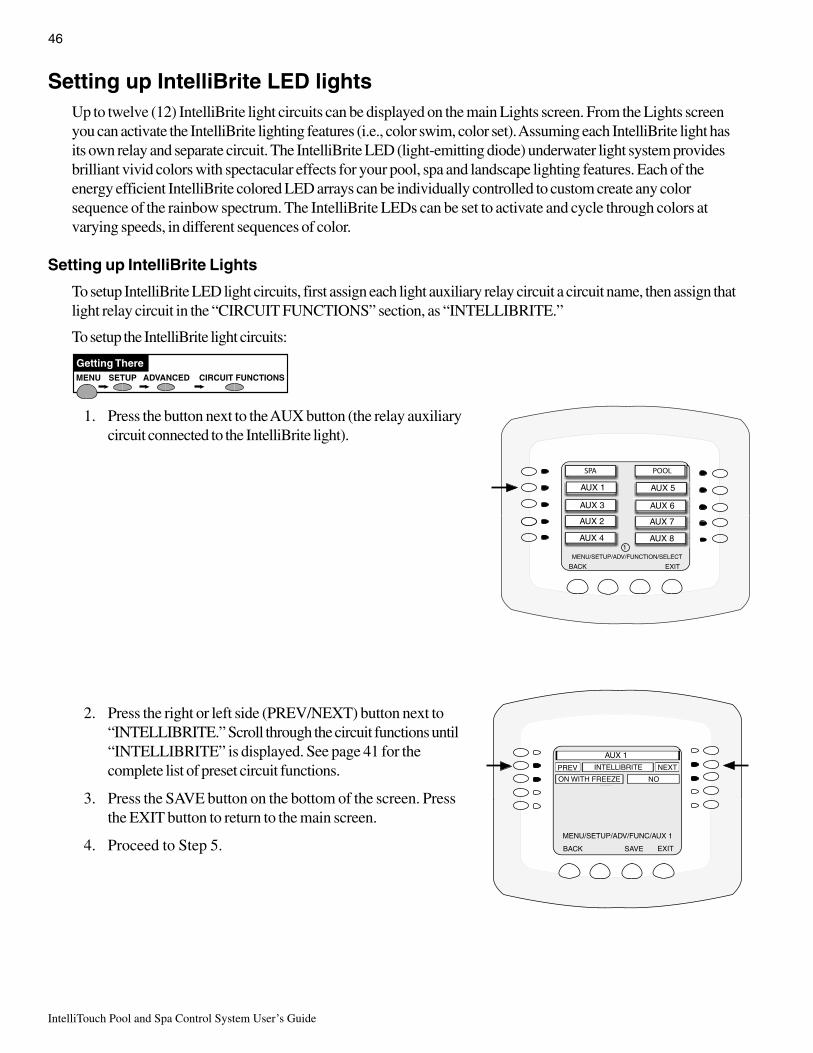
IntelliTouch Pool and Spa Control System User’s Guide
46
Setting up IntelliBrite LED lightsUp to twelve (12) IntelliBrite light circuits can be displayed on the main Lights screen. From the Lights screenyou can activate the IntelliBrite lighting features (i.e., color swim, color set). Assuming each IntelliBrite light hasits own relay and separate circuit. The IntelliBrite LED (light-emitting diode) underwater light system providesbrilliant vivid colors with spectacular effects for your pool, spa and landscape lighting features. Each of theenergy efficient IntelliBrite colored LED arrays can be individually controlled to custom create any colorsequence of the rainbow spectrum. The IntelliBrite LEDs can be set to activate and cycle through colors atvarying speeds, in different sequences of color.
Setting up IntelliBrite Lights
To setup IntelliBrite LED light circuits, first assign each light auxiliary relay circuit a circuit name, then assign thatlight relay circuit in the “CIRCUIT FUNCTIONS” section, as “INTELLIBRITE.”
To setup the IntelliBrite light circuits:
1. Press the button next to the AUX button (the relay auxiliarycircuit connected to the IntelliBrite light).
2. Press the right or left side (PREV/NEXT) button next to“INTELLIBRITE.” Scroll through the circuit functions until“INTELLIBRITE” is displayed. See page 41 for thecomplete list of preset circuit functions.
3. Press the SAVE button on the bottom of the screen. Pressthe EXIT button to return to the main screen.
4. Proceed to Step 5.
MENU SETUP CIRCUIT FUNCTIONSADVANCED
Getting There
AUX 2
AUX 3
AUX 1
AUX 4
AUX 7
AUX 6
AUX 5
AUX 8
MENU/SETUP/ADV/FUNCTION/SELECT
BACK EXIT
1
MENU/SETUP/ADV/FUNC/AUX 1
EXITBACK
NO
NEXT
AUX 1
PREV
ON WITH FREEZE
SAVE
INTELLIBRITE

47
IntelliTouch Pool and Spa Control System User’s Guide
Setting up IntelliBrite LED lights (Continued)
To assign IntelliBrite light circuits to the Lights screen:
5. Press the Lights button on the bottom ofthe screen.
6. Press the right side button next to“CONFIGURE.”
7. Press the button next to “NONE” to assignan IntelliBrite light circuit to the selectedbutton. Light names can be setup to displayon the left side for “Spa” features and onthe right side for the “Pool” features.
8. Press the top left or right side button to scroll through the available light circuits which can be used for theIntelliBrite lighting features. Select at the circuit name you wish to use. The displayed circuit names arecircuit names that were previously assigned when assigning a circuit function. If there are no circuitsavailable for selection, refer to “Assigning Circuit Names, ” on page 35, and “Assigning Circuit Functionsand Freeze Protection” on page 39 for more information.
LIGHTS CONFIGURE NEXT TO "NONE"PRESS BUTTON
Getting There
Available light circuit
LIGHTS/CONFIG-SELECTION
EXITBACK
NONE
POOL SAM 1POOL LIGHT
NEXT GROUP
SPA SAL
NONE
NONE
View/configure next sixlight circuits
Available light circuit
Lights screen using IntelliBrite lights
LIGHTS
ALL OFF SYNCSAVE ALL ON
CONFIGURENEXT GROUP
MODES INTELLIBRITE COLORS
No circuitsassigned to the
Lights screen
LIGHTS/CONFIG/POOL SAM 1
PREV NEXT
PREV
PREV
PREV
NEXT
NEXT
NEXTPOOL SAM 1
WHITE
1ST POSITION
DELAY 5 SECS
SAVE EXIT
Select the light circuitSelect the color
Color Swim: Set the delaytime between lights
Select the light position

IntelliTouch Pool and Spa Control System User’s Guide
48
Setting up IntelliBrite LED lights (Continued)
Selecting IntelliBrite Modes
From the “Modes” screen you can select various preset show color lighting effects, such as “American mode”and “Sunset mode,” and Sam Style (an emulation of the Pentair Water Pool and Spa SAm color scheme).Using the “Hold” and “Recall” feature (see page 49) you can also capture and save a unique color effect torecall at a later time.
Modes screen
To access the IntelliBrite “Modes” features from the Lights screen, press the Lights button on the bottom ofthe screen, then press the left side button next to “MODES.”
Modes: Color light shows
There are six pre-programmed color light shows available to enhance your backyard pool environment.Note: If the light was not previously on, after pressing a color show mode button, no illumination willoccur for up to ten (10) seconds (depending on the selection), then a white light will momentarilyilluminate, followed by the color show mode selection. If the light was previously on, pressing the a colorshow mode button will momentarily illuminate the previously selected color before changing to theselected color show.
• SAm mode: Emulates SAm lights color scheme• Party mode: Rapid color changing building the energy and excitement• Romance mode: Slow color transitions creating a mesmerizing and calming effect• Caribbean: Transitions between a variety of blues and greens• American Mode: Patriotic red, white and blue transition• Sunset Mode: Dramatic transitions of orange, red and magenta tones• Royalty Mode: Richer, deeper, color tones
Feature: Swim
The “Swim” SAm Style feature cycles through white, magenta, blue and green colors. This feature emulates thePentair Water Pool and Spa “Color Swim” feature (see page 42). Note: If the light was not previously on,after pressing the SWIM button, no illumination will occur for approximately six (6) seconds followed bythe “COLOR SWIM” feature selection. If the light was previously on, after pressing the SWIM button,the previously selected color will momentarily illuminate, no illumination will occur for approximatelysix (6) seconds followed by the “COLOR SWIM” feature selection.
WARNING - During the off/on switchingprocess, before the selected color isdisplayed, no illumination will occur. Thisoperating mode is normal during theswitching process. During this period thepool and spa will be dark and precautionsshould be taken to avoid unforeseenaccidents. Failure to observe this warningmay result in serious injury or death to pooland spa users.
Color lightshows
LIGHT/INTELLIBRITE/MODES
BACK EXIT
ROMANCE MODE SUNSET MODE
HOLD INTELLIBRITE RECALL
SWIM SAM STYLE COLOR SET
PARTY MODE AMERICAN MODE
CARIBBEAN ROYAL MODE
Color lightshows
HoldSwim
RecallColor Set

49
IntelliTouch Pool and Spa Control System User’s Guide
Setting up IntelliBrite LED lights (Continued)
Feature: Color Set
The “Color Set” SAm Style feature allows any combination of up to 12 IntelliBrite lights, and Pentair WaterPool and Spa SAm, SAL and or Fiberworks lighting (see page 42) to be preset to specific colors. To enablethis feature, first select the light color from the “Colors” screen, then press the button next to “Color Set” tochange the lights to the selected color. Note: If the light was not previously on, after pressing the COLORSET button, no illumination will occur for approximately six (6) seconds followed by the “COLOR SET”feature selection. If the light was previously on, after pressing the COLOR SET button, the previouslyselected color will momentarily illuminate, no illumination will occur for approximately six (6) secondsfollowed by the “COLOR SET” feature selection.
Fixed Colors Screen
There are five (5) fixed colors to choose from to create a spectacular underwater lighting effect. The fixedcolors are: Blue, Green, Red, White and Magenta. You can switch each light on or off from this screen (seeabove) by pressing the button next to the name of the color light. Note: If the light was not previously on,after pressing a color button, no illumination will occur for up to ten (10) seconds (depending on theselection), then a white light will momentarily illuminate, followed by the color selection. If the light waspreviously on, pressing the color button will momentarily illuminate the previously selected color beforechanging to the selected color mode.
To select a fixed color:
1. To access the IntelliBrite fixed “Colors” screen fromthe Main screen, press the Lights button on thebottom of the screen, then press the right side buttonnext to “COLORS.”
2. To activate a color, press the button next to the nameof the color.
Fixed Colors: Hold/Recall Feature
Use the “Hold” and “Recall” feature to capture and save the selected color and recall it at a later time. Note:After pressing the HOLD or RECALL button, no illumination will occur for up to 10 seconds, then awhite light will momentarily illuminate, followed by the saved color.
WARNING - During the off/on switchingprocess, before the selected color isdisplayed, no illumination will occur. Thisoperating mode is normal during theswitching process. During this period thepool and spa will be dark and precautionsshould be taken to avoid unforeseenaccidents. Failure to observe this warningmay result in serious injury or death to pooland spa users.
LIGHTS
ALL OFF SYNCSAVE ALL ON
CONFIGURE
POOL SAM 1POOL LIGHT
NEXT GROUP
MODES INTELLIBRITE COLORS
SPA LIGHTSPA SAL
PressColorsbutton forFixedColorsselection
LIGHT/INTELLIBRITE/COLORS
BACK EXIT
GREEN MAGENTA
HOLD INTELLIBRITE RECALL
SWIM SAM STYLE COLOR SET
BLUE WHITE
RED
Fixed ColorsFixed Colors
HoldSwim
RecallColor Set

IntelliTouch Pool and Spa Control System User’s Guide
50
Setting up MagicStream LaminarsThe MagicStream Laminar provide a clear, turbulence-free stream of water that is lit with a fiber optic cable, oran LED light for a dazzling nighttime effect. The 12 VAC powered LED light can generate a series ofmulticolored light shows, or can be set to display a continuous, single color. If desired, the built-in solenoid“thumper” can create a random “wrinkle,” in the Laminar’s stream, causing it to display a brilliant spot of lightthat moves along the stream’s arc. The light enhancer can be adjusted to maximize the light in the arc.
Up to twelve (12) MagicStream Laminar circuits can be displayed on the main Lights screen, assuming eachlaminar has its own relay and separate circuit.. From the Lights screen you can activate the MagicStreamlaminars (changing color modes, turn Thumper on/off, Hold and Reset). For more information, see theMagicStream Installation Guide, P/N 520969.
Setting up MagicStream Laminar LED Lights
To setup MagicStream laminar circuits, first assign each laminar auxiliary relay circuit a circuit name, thenassigned the laminar relay circuit name in the “CIRCUIT FUNCTIONS” menu, as “MAGICSTREAM.”
To setup the MagicStream laminar circuits:
1. Press the button next to the AUX button (the relay circuit connected to the laminar).
2. Press the right or left side (PREV/NEXT) button next to “MAGICSTREAM.” Scroll through the circuitfunctions until “MAGICSTREAM” is displayed. See page 41 for the complete list of preset circuitfunctions.
3. Press the SAVE button on the bottom of the screen. Press the EXIT button to return to the main screen.
4. Proceed to Step 5.
MENU/SETUP/ADV/FUNC/AUX 1
EXITBACK
NO
NEXT
AUX 4
PREV
ON WITH FREEZE
SAVE
MAGICSTREAM
AUX 2
AUX 3
AUX 1
AUX 4
AUX 7
AUX 6
AUX 5
AUX 8
MENU/SETUP/ADV/FUNCTION/SELECT
BACK EXIT
1
MENU SETUP CIRCUIT FUNCTIONSADVANCED
Getting There

51
IntelliTouch Pool and Spa Control System User’s Guide
To display the assigned MagicStream circuit on the Lights screen:
5. From the main screen, press the Lights button on the bottomof the screen.
6. Press the right side button next to “CONFIGURE” to assign thepreviously assigned MagicStream laminar circuits to the “Lights”screen. Note: The screen on right shows IntelliBrite light circuitsalready displayed on the “Lights” screen. The MagicStreamcircuits are not displayed until assigned to the “Lights” screen.
7. Press the button next to “NONE” to assign a laminar light circuitto the selected button.
8. Press the top left or right side button to scroll through theassigned light circuits. Select the previously assignedMagicStream circuit name (i.e. Pool Laminar 1) or AUX circuit.Repeat this step for other laminar circuits (i.e. Pool Laminar 1).If there are no circuits available for selection, refer to “AssigningCircuit Names, ” on page 35, and “Assigning Circuit Functionsand Freeze Protection” on page 39 for more information.
9. Press the SAVE button on the bottom of the screen. Press theBACK button to return to the main screen. The MagicStreamlaminar circuit will be displayed on the “Lights” screen, as shown below.
To activate the MagicStream features, see the next page.
MagicStream circuitbuttons
Lights screen using IntelliBrite lights and MagicStream laminars
IntelliBritebutton forColor and
Mode Lightshow
LIGHTS
ALL OFF SYNCSAVE ALL ON
CONFIGURE
POOL LIGHT
NEXT GROUP
INTELLIBRITE MAGICSTREAM
SPA LIGHT POOL LAMINAR 1
POOL LAMINAR 2
MagicStreambutton forlaminarfeaturesscreen
LIGHTS
ALL OFF SYNCSAVE ALL ON
CONFIGURE
POOL LIGHT
NEXT GROUP
INTELLIBRITE MAGICSTREAM
SPA LIGHT
LIGHTS/CONFIG/POOL LAMINAR 1
PREV NEXT
PREV
PREV
PREV
NEXT
NEXT
NEXTPOOL LAMINAR 1
NOT APPLICABLE
SAVE EXIT
NOT APPLICABLE
NOT APPLICABLE

IntelliTouch Pool and Spa Control System User’s Guide
52
Using the MagicStream Laminar Features
The MagicStream laminar features are displayed on the MagicStream screen. Each time the MagicStreamlaminar is switched on using the Light screen circuit buttons, it resumes with the same features in operation aswhen last switched off. The MagicStream features are as follows:
Thumper - Pressing this button creates a "wrinkle" in the laminar stream, producing a brilliant spot of light inthe laminar arc.
Reset - Pressing this button reverts to the Random color changing mode with the Thumper ON.
Toggle Mode - Pressing this button (each successive OFF/ON combination) will cycle through Sync, Randomand Party. Color changing mode - The color of the light changes automatically, according to one the followingthree programs:
Sync - Colors will change at ten second intervals. In this mode, multiple laminars will synchronizecolors together. Note: To sync multiple laminars (two or more AUX circuits), be sure to define the“MagicStream” circuits in the Circuit Functions screen and also define the AUX circuits in the Lightsscreen (CONFIGURE, 0-6 or 7-12).
Random - Colors will change at ten second intervals in a random sequence. In this mode, multiplelaminars will NOT synchronize colors together.
Party - Colors will change randomly and slowly at first, then speed up, until the sequence ends withquick flashes and strobes. The sequence then repeats, beginning with the slow changes. In thismode, multiple Laminars will NOT synchronize colors together.
Hold/Stop - Select Hold/Stop to capture the current color effect while colors are changing. The colors will stopchanging. Selecting Hold/Stop again will resume the color changing mode.
To access the MagicStream laminar features screen:
1. From the main screen, press the Lights button on the bottom of the screen.
2. Press the button next to MAGICSTREAM to access the laminar features screen.
3. To activate a laminar feature, press the button next to the desired feature.
MagicStream circuitbuttons
LIGHTS
ALL OFF SYNCSAVE ALL ON
CONFIGURE
POOL LIGHT
NEXT GROUP
INTELLIBRITE MAGICSTREAM
SPA LIGHT POOL LAMINAR 1
POOL LAMINAR 2
MagicStreambutton forlaminarfeaturesscreen
LIGHTS/MAGICSTREAM
EXITBACK
RESET
THUMPER TOGGLE MODE
HOLD / STOP
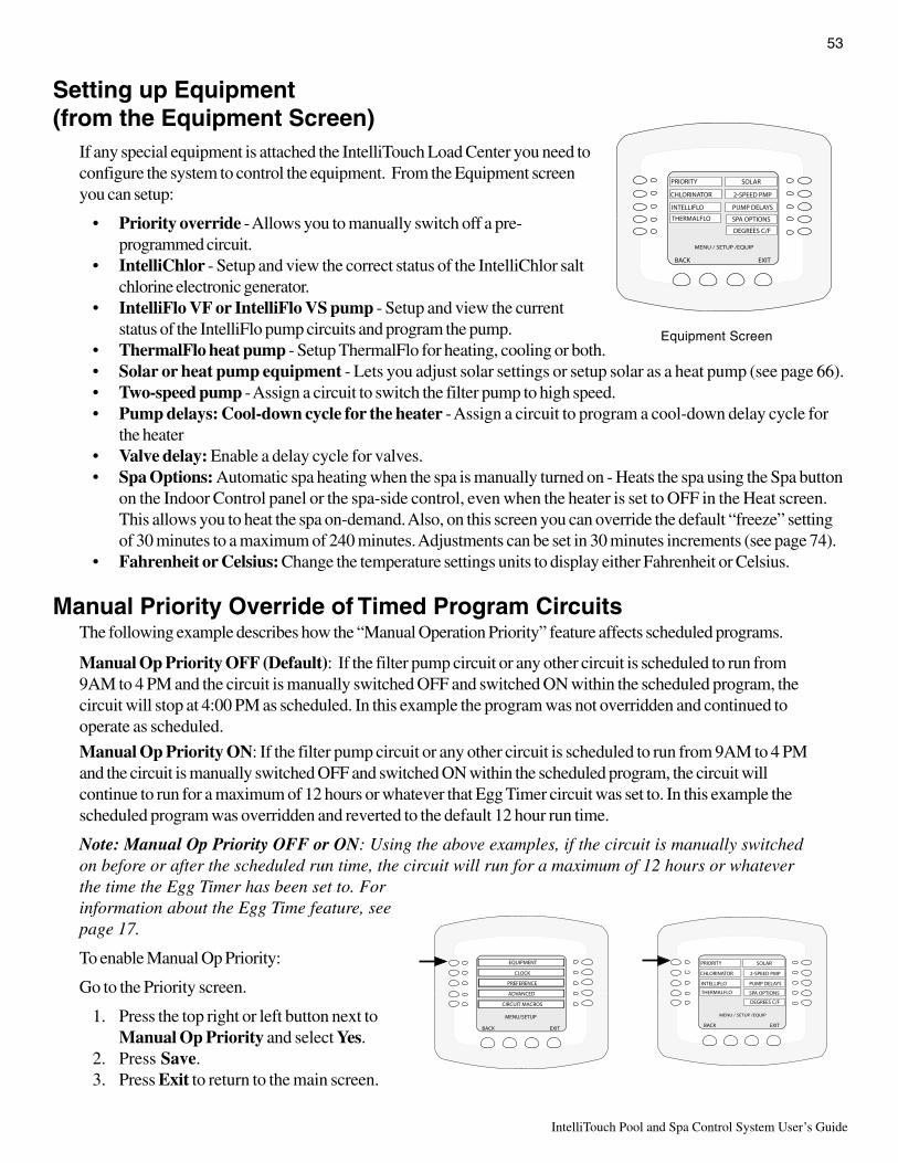
53
IntelliTouch Pool and Spa Control System User’s Guide
Setting up Equipment(from the Equipment Screen)
If any special equipment is attached the IntelliTouch Load Center you need toconfigure the system to control the equipment. From the Equipment screenyou can setup:
• Priority override - Allows you to manually switch off a pre-programmed circuit.
• IntelliChlor - Setup and view the correct status of the IntelliChlor saltchlorine electronic generator.
• IntelliFlo VF or IntelliFlo VS pump - Setup and view the currentstatus of the IntelliFlo pump circuits and program the pump.
• ThermalFlo heat pump - Setup ThermalFlo for heating, cooling or both.• Solar or heat pump equipment - Lets you adjust solar settings or setup solar as a heat pump (see page 66).• Two-speed pump - Assign a circuit to switch the filter pump to high speed.• Pump delays: Cool-down cycle for the heater - Assign a circuit to program a cool-down delay cycle for
the heater• Valve delay: Enable a delay cycle for valves.• Spa Options: Automatic spa heating when the spa is manually turned on - Heats the spa using the Spa button
on the Indoor Control panel or the spa-side control, even when the heater is set to OFF in the Heat screen.This allows you to heat the spa on-demand. Also, on this screen you can override the default “freeze” settingof 30 minutes to a maximum of 240 minutes. Adjustments can be set in 30 minutes increments (see page 74).
• Fahrenheit or Celsius: Change the temperature settings units to display either Fahrenheit or Celsius.
Manual Priority Override of Timed Program CircuitsThe following example describes how the “Manual Operation Priority” feature affects scheduled programs.
Manual Op Priority OFF (Default): If the filter pump circuit or any other circuit is scheduled to run from9AM to 4 PM and the circuit is manually switched OFF and switched ON within the scheduled program, thecircuit will stop at 4:00 PM as scheduled. In this example the program was not overridden and continued tooperate as scheduled.
Manual Op Priority ON: If the filter pump circuit or any other circuit is scheduled to run from 9AM to 4 PMand the circuit is manually switched OFF and switched ON within the scheduled program, the circuit willcontinue to run for a maximum of 12 hours or whatever that Egg Timer circuit was set to. In this example thescheduled program was overridden and reverted to the default 12 hour run time.
Note: Manual Op Priority OFF or ON: Using the above examples, if the circuit is manually switchedon before or after the scheduled run time, the circuit will run for a maximum of 12 hours or whateverthe time the Egg Timer has been set to. Forinformation about the Egg Time feature, seepage 17.
To enable Manual Op Priority:
Go to the Priority screen.
1. Press the top right or left button next toManual Op Priority and select Yes.
2. Press Save.3. Press Exit to return to the main screen.
MENU / SETUP /EQUIP
BACK EXIT
CHLORINATOR
PRIORITY
INTELLIFLO
SOLAR
2-SPEED PMP
PUMP DELAYS
SPA OPTIONS
DEGREES C/F
THERMALFLO
Equipment Screen
MENU/SETUP
BACK EXIT
EQUIPMENT
CLOCK
PREFERENCE
ADVANCED
CIRCUIT MACROS
MENU / SETUP /EQUIP
BACK EXIT
CHLORINATOR
PRIORITY
INTELLIFLO
SOLAR
2-SPEED PMP
PUMP DELAYS
SPA OPTIONS
DEGREES C/F
THERMALFLO

IntelliTouch Pool and Spa Control System User’s Guide
54
Chlorine GeneratorThe IntelliTouch system is designed to operate with the following salt chlorine generators:
• Pentair Water Pool and Spa IntelliChlor• GoldLine Aqua Rite™
• Clear Tech Automation AutoClear® Plus• AutoPilot Pool Pilot® Digital
Note: Call your manufacturer for compatibility with IntelliTouch systems.
Activating the ChlorinatorFor IntelliTouch to control and operate the chlorinator, first enable the chlorinator from the IntelliTouch IndoorControl Panel. If the chlorinator control is enabled, the controls on the chlorinator are disabled and can only beoperated by IntelliTouch. When the chlorinator control is disabled from IntelliTouch, the chlorinator will still berunning but must be controlled at the chlorinator control panel.
Go to the Chlorinator screen.
To view the chlorination status and adjust the spa or poolchlorination level:
• STATUS: Displays the current chlorinator operatingcondition. If a problem occurs with the chlorinator, anerror codes will be displayed on the status line.
• WATER SALT LEVEL: Displays how much salt (inparts per million (ppm) is in the water. See chlorinatormanufacturer’s instructions for recommended salt levels.
• SPA / POOL (0 -100%): Displays the current spa andpool chlorination output level from 0 to 100%.
• CONTROL ENABLED: Press the button next to YES until NO is displayed to disable thecontrol of the chlorination interface from the Indoor Control Panel.
• To enable or disable the chlorinator: Press the button next to CONTROL ENABLED and select YES toallow IntelliTouch to control of the chlorinator. Select NO to disable IntelliTouch control. Press Save whendone to return to the Equipment screen.
Adjusting the Chlorine Output LevelIn an effort to prevent over chlorination of the spa, theIntelliTouch system will automatically drop the chlorineoutput levels to 1/20th of the current pool output when thespa is switched on. For example, if the pool output level isset to 60%, when the spa is switched on, the chlorinationlevel is reduced to 3%.
• To adjust the spa or pool chlorine output level:Press the button next to SPA / POOL. Press the (-) or(+) button to decrease or increase the chlorine outputlevel (from 0 to 100%) for the spa or pool water.Press Save when done to return to the Equipmentscreen. Press Exit to return to the main screen.
MENU SETUP EQUIPMENT CHLORINATOR
Getting There
MENU/SETP/EQUIP/INTELLICHLOR
BACK EXIT
MODEL NAME HERE
STATUS
CONTROL ENABLED
WATER SALT LEVEL
CHLOR
OK - NO ERRORS
2900 PPM
YES
SUPER
SPA 0% POOL 50%
MENU/SETUP/EQUIP/CHLOR/OUTPUT
BACK EXIT
- SPA 0% +
- POOL 50% +
Spa and Pool Chlorine Output Level Screen
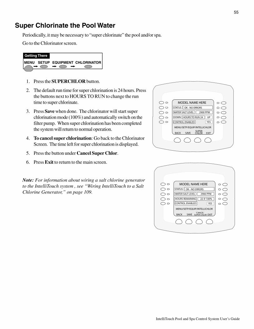
55
IntelliTouch Pool and Spa Control System User’s Guide
MENU/SETP/EQUIP/INTELLICHLOR
BACK EXIT
MODEL NAME HERE
STATUS
DOWN
CONTROL ENABLED
WATER SALT LEVEL
CHLOR
OK - NO ERRORS
2900 PPM
UPHOURS TO RUN 24
YES
SUPERSAVE
MENU/SETP/EQUIP/INTELLICHLOR
BACK EXIT
MODEL NAME HERE
STATUS
CONTROL ENABLED
WATER SALT LEVEL
SUPER CHLOR
OK - NO ERRORS
2900 PPM
22 @ 100%HOURS REMAINING
YES
'CANCEL'SAVE
MENU SETUP EQUIPMENT CHLORINATOR
Getting There
Super Chlorinate the Pool WaterPeriodically, it may be necessary to “super chlorinate” the pool and/or spa.
Go to the Chlorinator screen.
1. Press the SUPERCHLOR button.
2. The default run time for super chlorination is 24 hours. Pressthe buttons next to HOURS TO RUN to change the runtime to super chlorinate.
3. Press Save when done. The chlorinator will start superchlorination mode (100%) and automatically switch on thefilter pump. When super chlorination has been completedthe system will return to normal operation.
4. To cancel super chlorination: Go back to the ChlorinatorScreen. The time left for super chlorination is displayed.
5. Press the button under Cancel Super Chlor.
6. Press Exit to return to the main screen.
Note: For information about wiring a salt chlorine generatorto the IntelliTouch system , see “Wiring IntelliTouch to a SaltChlorine Generator,” on page 109.

IntelliTouch Pool and Spa Control System User’s Guide
56
IntelliFlo (model VF) and IntelliFlo 4x160 (VS) pump setup
Setting up IntelliFloThe IntelliFlo pump can be remotely controlled by an IntelliTouch system using the two-wire 50 foot RS-485communication cable (P/N 350122). IntelliFlo operations can be adjusted from the IntelliTouch indoor controlpanel or MobileTouch wireless remote. For more information refer to the IntelliFlo Installation and User’s Guide(P/N 350075) and the IntelliFlo 4x160 Installation and User’s Guide (P/N 357269).
How many pumps will IntelliTouch support?IntelliTouch can support up to eight IntelliFlo and four IntelliFlo 4 pumps in any combination with up to eightGPMs or RPMs per pump. For example pumps can be connected to IntelliTouch as follows:
• 8 IntelliFlo• 7 IntelliFlo + 1 IntelliFlo 4• 5 IntelliFlo + 3 IntelliFlo 4• 4 IntelliFlo + 4 IntelliFlo 4 (or only 4 IntelliFlo 4 pumps)
Connecting power to an IntelliFlo pumpThe IntelliFlo pump is designed to be permanently connected to its power source. Typically the pump receivespower directly from the circuit breaker. No contactor or motor starter is required. The drive controls thestarting and stopping of the pump. If the IntelliFlo pump is connected to an automation system, such as theIntelliTouch automation system, the drive must be powered up to receive and respond to the RS-485 serialcommunication from the automation system. However, the pump can be operated in “stand-alone” mode,starting and stopping when power is applied or removed. When the drive powers up it will return to the modeand run status that it was in when power was removed. This setup maybe appropriate if you need to use existingrelays or timers.
Assigning an IntelliFlo pump addressBefore assigning a pump address in the IntelliTouch indoor control panel, first set the address onthe pump itself. If there is only one pump, it is always seen as pump #1 by IntelliTouch. In thiscase you do not need to set the pump address. When using multiple IntelliFlo pumps withIntelliTouch you need to assign an address to each pump. The address can be set to #1, #2, #3,#4, #5, #6, #7, or #,8. The address set at the pump must match the IntelliFlo pump numberselected in the IntelliTouch indoor control panel.
Note: IntelliFlo 4 pumps cannot be connected in series with other pumps.Check valves must be used when a pump is used in parallel with other pumps.
To assign an IntelliFlo pump address:
1. Press the Start/Stop button to stop the pump. Be sure that the green power LED is on andthe pump is stopped.
2. Press the Menu button.3. Press the Up and Down arrow buttons to scroll through the menu items. Press the Select
button to access the “Pool Data” menu.4. Press the Select button to access the “Pump Address” setting.5. Press the Select button to change the current pump address.6. To enter the new address number, press the Left and Right arrows to select which digit to
modify, then use the Up and Down arrows to change the selected digit.7. When you are done assigning the pump address number, press the Enter button to save
the changes. To cancel any changes, press the Escape button to exit edit mode without saving.
Filter VacuumBackWash
Manual
Enter
Select
ResetFeature2
Feature1
Menu
Escape
On
Warn.
Alarm
IntelliFlo®
MENU 12:15
Pool Data
StartStop
Filter VacuumBackWash
Manual
Enter
Select
StartStop ResetFeature
2Feature
1
Menu
Escape
On
Warn.
Alarm
IntelliFlo®
Pool DataPool Data 12:0112:01
Pump AddressPump Address
1

57
IntelliTouch Pool and Spa Control System User’s Guide
IntelliFlo VF pump setup (Continued)
IntelliFlo menu optionsThe following screens are available in the EQUIPMENT > INTELLIFLO menu:
• IntelliFlo main pump status screens: Two status screens (pumps 1-4, pumps 5-8), each displaying theIntelliFlo pump number assignments and assigned circuit name for each pump
• IntelliFlo Set Parameters screen (page 58-62): From these screens you can set up the pump parameters(filtering, priming, backwash, vacuum), assign a circuit name, assign up eight pump flows (GPM), or view thecurrent pump status
IntelliFlo main pump assignment screensFrom these screens you can view the current pump address and circuit name for each pump.
MENU SETUP EQUIPMENT INTELLIFLO
Getting There
MENU/SETP/EQUIP/IFLO/SELECT
BACK EXIT
INTELLIFLO #6 NONE
NEXT GROUP OF PUMPS
INTELLIFLO #5 NONE
INTELLIFLO #8 NONE
INTELLIFLO #7 NONE
MENU/SETP/EQUIP/IFLO/SELECT
BACK EXIT
INTELLIFLO #2 NONE
NEXT GROUP OF PUMPS
INTELLIFLO 4 #1
INTELLIFLO 4 #4
INTELLIFLO #3 NONE
Press thisbutton to view
pumps 5-8
To access thepump
parameters,press selected
pump button
NOTE: INTELLIFLO “FREEZE” PROTECTION - If the IntelliFlo pump is ondue to a freeze condition (not switch on from a relay circuit state), and if afreeze speed/flow is set in IntelliTouch, this setting takes priority even if theprevious setting is lower than the default circuit speed. If no “freeze” protectionis set, the pump will be forced on at the default circuit speed/flow. Anyprogrammed or manual operation that actually switches on a circuit, will causethe pump to run at that speed if it is higher.
NOTE: INTELLIFLO IN “SERVICE MODE” - IntelliFlo VF and VS pumps willSTOP when IntelliTouch is in ‘Service” mode.
NOTE: INTELLIFLO VF PUMPS - If the IntelliFlo VF pump is just starting(requiring a prime) and SOLAR is available, solar will be delayed for five (5)minutes to allow the pump to prime. This only applies for IntelliFlo pump(s)assigned as to a “pool” pump.
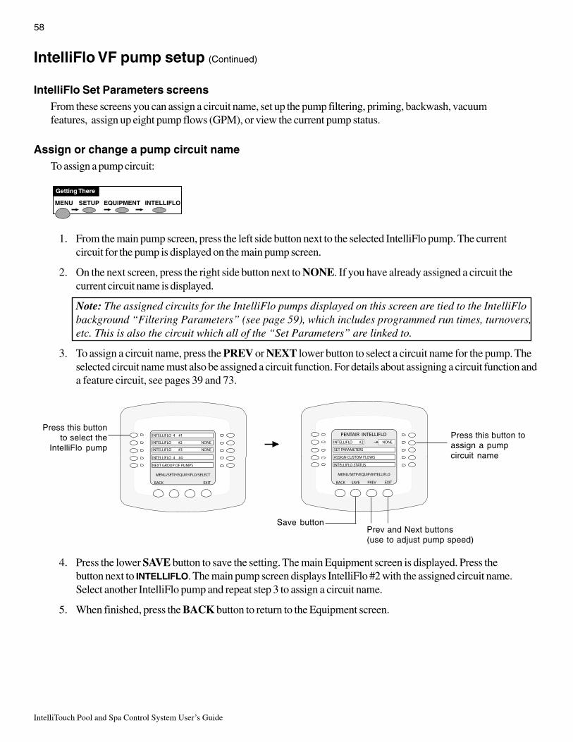
IntelliTouch Pool and Spa Control System User’s Guide
58
IntelliFlo VF pump setup (Continued)
IntelliFlo Set Parameters screensFrom these screens you can assign a circuit name, set up the pump filtering, priming, backwash, vacuumfeatures, assign up eight pump flows (GPM), or view the current pump status.
Assign or change a pump circuit nameTo assign a pump circuit:
1. From the main pump screen, press the left side button next to the selected IntelliFlo pump. The currentcircuit for the pump is displayed on the main pump screen.
2. On the next screen, press the right side button next to NONE. If you have already assigned a circuit thecurrent circuit name is displayed.
Note: The assigned circuits for the IntelliFlo pumps displayed on this screen are tied to the IntelliFlobackground “Filtering Parameters” (see page 59), which includes programmed run times, turnovers,etc. This is also the circuit which all of the “Set Parameters” are linked to.
3. To assign a circuit name, press the PREV or NEXT lower button to select a circuit name for the pump. Theselected circuit name must also be assigned a circuit function. For details about assigning a circuit function anda feature circuit, see pages 39 and 73.
4. Press the lower SAVE button to save the setting. The main Equipment screen is displayed. Press thebutton next to INTELLIFLO. The main pump screen displays IntelliFlo #2 with the assigned circuit name.Select another IntelliFlo pump and repeat step 3 to assign a circuit name.
5. When finished, press the BACK button to return to the Equipment screen.
MENU SETUP EQUIPMENT INTELLIFLO
Getting There
MENU/SETP/EQUIP/INTELLIFLO
BACK EXIT
PENTAIR INTELLIFLO
INTELLIFLO #2 NONE
ASSIGN CUSTOM FLOWS
INTELLIFLO STATUS
SET PARAMETERS
SAVE PREV
MENU/SETP/EQUIP/IFLO/SELECT
BACK EXIT
INTELLIFLO #2 NONE
NEXT GROUP OF PUMPS
INTELLIFLO 4 #1
INTELLIFLO 4 #4
INTELLIFLO #3 NONE
Press this button toassign a pumpcircuit name
Press this buttonto select the
IntelliFlo pump
Prev and Next buttons(use to adjust pump speed)
Save button

59
IntelliTouch Pool and Spa Control System User’s Guide
IntelliFlo VF pump setup (Continued)
Filtering parametersThe filtering parameters (pool size, turns per day) allows IntelliFlo to calculate the required flow rate whichcontrols the motor speed to keep a constant flow. You can set up to eight turns per day. It is recommended thatone turn per day for energy conservation be performed for most common residential pools. The “Manual Filter”option allows you to set the GPM to clean the filer by performing a “Backwash” cycle (see page 61).
MENU SETUP EQUIPMENT INTELLIFLO
Getting There
To set filtering parameters:
1. From the main pump screen, press the left side button next to the select IntelliFlo pump.
2. On the next screen, press the left side button next to SET PARAMETERS then on the following screenselect FILTERING PARAMETERS.
3. To adjust one of the parameters, use the right button to increase and the left button to decrease the parametervalue.
MENU/SETP/EQUIP/IFLO/PARAMS
BACK EXIT
PRIMING PARAMETERS
FILTERING PARAMETERS
VACUUM PARAMETERS
BACKWASH PARAMETERS
MENU/SETP/EQUIP/INTELLIFLO
BACK EXIT
PENTAIR INTELLIFLO
INTELLIFLO #2 NONE
ASSIGN CUSTOM FLOWS
INTELLIFLO STATUS
SET PARAMETERS
SAVE PREV
noitpircseD eulaV
snollaG/eziSlooP.)lagK(snollagfos’0001sadesserpxesieulavezisloopehT
emulovehT.emulovloopehtroflagK0001ot1morfretnEetaruccaeromehthguohtla,etamitseesolcaebnacrebmun.edomretlifgniyolpmenehwenodeblliwsnrutehtrettebeht
ehthtiwnoitanidroocnieulavsihtsesuedomretliFdna,swolf,setarnrutniatsusotedomretliFmorfsretemarap
.semit
552-0
yadrepsrevonruTsitI.yadrepsnrutthgieotpuotputesnacuoY
ygrenerofyadrepnrutenotesotdednemmocerrefer,oslA.slooplaitnedisernommoctsomrofnoitavresnoc.noitamrofnilanoitiddarofnoitadnemmocerrezitinasruoyot
8-1
MPGretliFlaunaM )MPG03sitluafeD(sitifinurlliwpmupehthcihwtawolfehtstesretliFlaunaM
ehtninurylnolliwpmupolFilletnIehT.yllaunamnodenrutfi,elpmaxeroF.semitdemmargorpehtgnirudedom'retliF'
tiucricloopehtrof)semitpots/trats(demmargorpsipmupehtromargorpsihT.yadyreveMP00:4otMA00:8morfnurot
tideepstahwtaetaluclacotolFilletnIybdesuerasmargorprof)s(revonrutehteveihcaotsemit’NO‘esohtnevignurtsum
.edomretlifcisabehtrofloopdezistaht
031-51
MENU/SETP/EQUIP/IFLO/PARAMS/FILTER
BACK EXIT
TURNOVERS PER DAY 2
MANUAL FILTER GPM 130
NEXT PAGE
POOL SIZE/GALLONS 35,000
SAVE
Press thisbutton toincrease
value
Press thisbutton todecreasevalue
Savebutton
4. When finished, press the lower SAVE button to savethe setting. The previous pump parameters screen isdisplayed. To modify another parameter select afeature from the parameter list. To exit, press theEXIT button to return to the Equipment screen.

IntelliTouch Pool and Spa Control System User’s Guide
60
IntelliFlo VF pump setup (Continued)
Priming parametersTo “prime” a pump means filling the pump and suction pipe with water. This process evacuates the air from allthe suction lines and the pump. It may take several minutes to prime depending on the depth of water, pipe sizeand length. It is easier to prime a pump if you allow all the air to escape from the pump and pipes. The watercannot enter unless the air can escape. Pumps do not hold prime, the pool piping system has that task. Primingis a function used every time the motor is started with a flow as reference. The “Priming Flow” function ensuresthe proper operation of the pump. The “System Priming Time” function ensures proper operation of the wholepool system. When the pump is priming, the control panel LCD displays “Priming” and then for a momentdisplays “Primed” when priming is complete.
To set the priming parameters:
1. From the main pump screen, press the left side button next to the select IntelliFlo pump.2. On the next screen, press the left side button next to SET PARAMETERS then on the following screen
select PRIMING PARAMETERS.3. To adjust one of the parameters, use the right button to increase and the left button to decrease the parameter
value.4. When finished, press the lower SAVE button to save the setting. The previous pump parameters screen is
displayed. To modify another parameter select a feature from the parameter list. To exit, press the EXITbutton to return to the Equipment screen.
noitpircseD eulaV
MPGwolFemirPxaM )MPG55sitluafeD(-ehtetaitogenlliwretemarapsihtstratspmupehtemityrevE
egamadtnempiuqe,hgihootsiwolfehtfI.pmupehtfowolfmumixamsi”wolf“sihT.emirptonlliwpmupehtwolotsiwolfehtfI.rucconac
revenlliwpmupehT.tnemtsujdaeriuqeryamdnatnednepedmetsysehtrofnommocsiti,revewoh,ottessiretemarapsihtnahteromwolfpeekotyrtsyawlA.gnimirpelihwylkciuqnwoddnapupmarotpmup
.ytefasdnasgnivastsocrofelbissopsawolsawolfsiht
031-51MPG
emiTemirPxaM ).nim51sitluafeD(-dnayrtolFilletnItnawuoytahtemitehttesotretemarapsihtesUlliwolFilletnIehttahtrebmemeR.rorrenastropertierofebemirpehT.elcycsihthguorhtseogdnastratstiemityreveemirpniattaerofebsetunim51tuobadnatshtiwnaclaeslacinahcemolFilletnI
ateglliwuoyrekciuqehtemitehtrewolehT.sruccoegamaderevesloopdebmulpllewA.emirpottluciffidsimetsysehtfirorregnimirp
03nahtsselniemirpdluohsdevomerreniartsehtgnivahtuohtiwadnagninaelcrofdevomerneebsahreniartsehtfI.sdnoces
06tuobaniemirpdluohstimetsysehtnisiriafotnuomalaitnatsbus.tnereffideblliwsmetsyslla,revewoh,egarevaehtnosdnoces09ot
51-1setunim
emiTemirPmetsyS ).nim0sitluafeD(-emitfodoireptrohsaniemirplliwtinuegarevaehttahtrebmemeR
sitierusekamotflestirotinomotytilibaehtsaholFilletnIehtesuacebswolfhgiheriuqertahtsmetsysrofsi”emiTemirPmetsyS“.demirp
siemiteromtahtdemeedsititubedivorpnacwolfgnimirptahterpamargorpnacredliubehT.riaehtllaeveileryllufotdedeen
riaehtgniveilernidiaot,setunim5otpu,emitfotnuomadenimretedmetsyS“ehT.gnibmulplacitrevxelpmocrosretliftluciffidmorf
emocebspartriaegralerehwdesuebylnodluohs”emiTemirPsihtnehwresuehtmrofnilliwyalpsidehT.metsysehtnihtiwsmelborp
hcaetaelcycgnimirpehtgniruddehsinifsitinehwdnadegagnesi.elcycputrats
5-0setunim
MENU/SETP/EQUIP/IFLO/PARAMS/PRIMING
BACK EXIT
MAX PRIME TIME 15
SYSTEM PRIME TIME 5
MAX PRIME FLOW GPM 130
SAVE
Press thisbutton toincrease
value
Press thisbutton todecreasevalue
Savebutton
MENU SETUP EQUIPMENT INTELLIFLO
Getting There
MENU/SETP/EQUIP/IFLO/PARAMS
BACK EXIT
PRIMING PARAMETERS
FILTERING PARAMETERS
VACUUM PARAMETERS
BACKWASH PARAMETERS
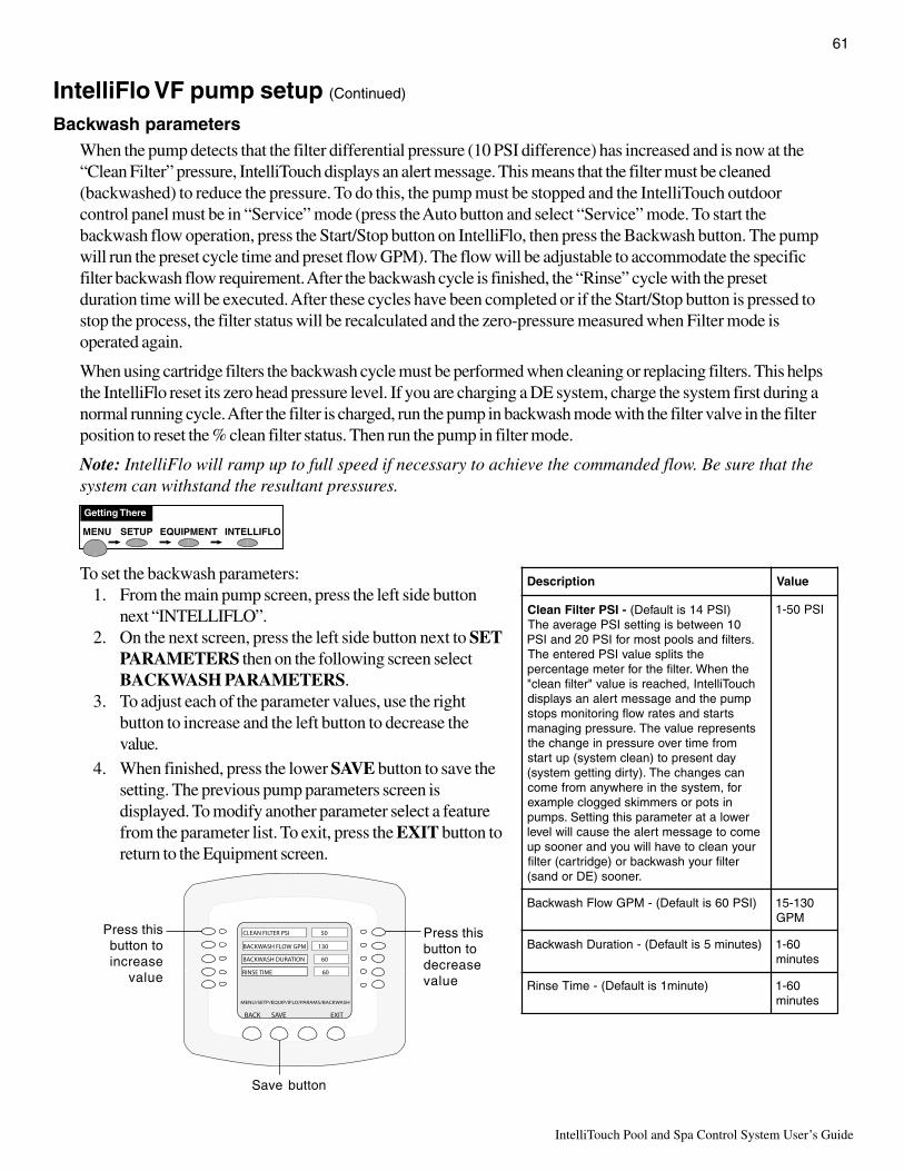
61
IntelliTouch Pool and Spa Control System User’s Guide
IntelliFlo VF pump setup (Continued)
Backwash parametersWhen the pump detects that the filter differential pressure (10 PSI difference) has increased and is now at the“Clean Filter” pressure, IntelliTouch displays an alert message. This means that the filter must be cleaned(backwashed) to reduce the pressure. To do this, the pump must be stopped and the IntelliTouch outdoorcontrol panel must be in “Service” mode (press the Auto button and select “Service” mode. To start thebackwash flow operation, press the Start/Stop button on IntelliFlo, then press the Backwash button. The pumpwill run the preset cycle time and preset flow GPM). The flow will be adjustable to accommodate the specificfilter backwash flow requirement. After the backwash cycle is finished, the “Rinse” cycle with the presetduration time will be executed. After these cycles have been completed or if the Start/Stop button is pressed tostop the process, the filter status will be recalculated and the zero-pressure measured when Filter mode isoperated again.
When using cartridge filters the backwash cycle must be performed when cleaning or replacing filters. This helpsthe IntelliFlo reset its zero head pressure level. If you are charging a DE system, charge the system first during anormal running cycle. After the filter is charged, run the pump in backwash mode with the filter valve in the filterposition to reset the % clean filter status. Then run the pump in filter mode.
Note: IntelliFlo will ramp up to full speed if necessary to achieve the commanded flow. Be sure that thesystem can withstand the resultant pressures.
To set the backwash parameters:1. From the main pump screen, press the left side button
next “INTELLIFLO”.2. On the next screen, press the left side button next to SET
PARAMETERS then on the following screen selectBACKWASH PARAMETERS.
3. To adjust each of the parameter values, use the rightbutton to increase and the left button to decrease thevalue.
noitpircseD eulaV
-ISPretliFnaelC )ISP41sitluafeD(01neewtebsignittesISPegarevaehT
.sretlifdnaslooptsomrofISP02dnaISPehtstilpseulavISPderetneehT
ehtnehW.retlifehtrofretemegatnecrephcuoTilletnI,dehcaersieulav"retlifnaelc"
pmupehtdnaegassemtrelanasyalpsidstratsdnasetarwolfgnirotinomspots
stneserpereulavehT.erusserpgniganammorfemitrevoerusserpniegnahcehtyadtneserpot)naelcmetsys(putrats
nacsegnahcehT.)ytridgnittegmetsys(rof,metsysehtnierehwynamorfemoc
nistoprosremmiksdeggolcelpmaxerewolataretemarapsihtgnitteS.spmup
emocotegassemtrelaehtesuaclliwlevelruoynaelcotevahlliwuoydnarenoospu
retlifruoyhsawkcabro)egdirtrac(retlif.renoos)EDrodnas(
ISP05-1
-MPGwolFhsawkcaB )ISP06sitluafeD( 031-51MPG
-noitaruDhsawkcaB )setunim5sitluafeD( 06-1setunim
-emiTesniR )etunim1sitluafeD( 06-1setunim
MENU SETUP EQUIPMENT INTELLIFLO
Getting There
4. When finished, press the lower SAVE button to save thesetting. The previous pump parameters screen isdisplayed. To modify another parameter select a featurefrom the parameter list. To exit, press the EXIT button toreturn to the Equipment screen.
MENU/SETP/EQUIP/IFLO/PARAMS/BACKWASH
BACK EXIT
BACKWASH FLOW GPM 130
RINSE TIME 60
CLEAN FILTER PSI 50
SAVE
BACKWASH DURATION 60
Press thisbutton toincrease
value
Press thisbutton todecreasevalue
Save button
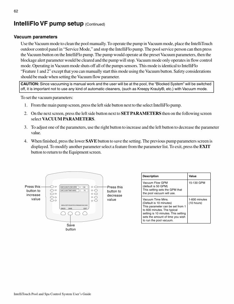
IntelliTouch Pool and Spa Control System User’s Guide
62
IntelliFlo VF pump setup (Continued)
Vacuum parametersUse the Vacuum mode to clean the pool manually. To operate the pump in Vacuum mode, place the IntelliTouchoutdoor control panel in “Service Mode,” and stop the IntelliFlo pump. The pool service person can then pressthe Vacuum button on the IntelliFlo pump. The pump would operate at the preset Vacuum parameters, then theblockage alert parameter would be cleared and the pump will stop. Vacuum mode only operates in flow controlmode. Operating in Vacuum mode shuts off all of the pumps sensors. This mode is identical to IntelliFlo“Feature 1 and 2” except that you can manually start this mode using the Vacuum button. Safety considerationsshould be made when setting the Vacuum flow parameter.
CAUTION: Since vacuuming is manual work and the user will be at the pool, the “Blocked System” will be switchedoff, it is important not to use any kind of automatic cleaners, (such as Kreepy Krauly®, etc.) with Vacuum mode.
To set the vacuum parameters:
1. From the main pump screen, press the left side button next to the select IntelliFlo pump.
2. On the next screen, press the left side button next to SET PARAMETERS then on the following screenselect VACUUM PARAMETERS.
3. To adjust one of the parameters, use the right button to increase and the left button to decrease the parametervalue.
4. When finished, press the lower SAVE button to save the setting. The previous pump parameters screen isdisplayed. To modify another parameter select a feature from the parameter list. To exit, press the EXITbutton to return to the Equipment screen.
noitpircseD eulaV
MPGwolFmuucaV)MPG05sitluafed(
tahtMPGehtstesgnittessihT.esulliwmuucavloopeht
MPG031-51
.sniMemiTmuucaV)setunim01sitluafeD(
1morftesebnacretemarapsihTlacipytehT.setunim006ot
gnittessihT.setunim01signitteshsiwuoyemitfotnuomaehtstes
.muucavloopehtnurot
setunim006-1)sruoh01(
MENU/SETP/EQUIP/IFLO/PARAMS/VACUUM
BACK EXIT
VACUUM TIME MINS 75
VACUUM FLOW GPM 130
SAVE
Press thisbutton toincrease
value
Press thisbutton todecreasevalue
Savebutton

63
IntelliTouch Pool and Spa Control System User’s Guide
IntelliFlo VF pump setup (Continued)
Assign custom flowsFrom the Assign Custom Flows screen you can assign different (normally higher) flows to circuits/features. Forexample you can set your SPA to run at 80 GPM. This way when you switch to spa mode, the pump goes fromthe calculated fitter rate of about 28 GPM to 80 GPM while you use the spa. You have a waterfall, and require60 GPM when it’s switched on.
To assign a specific flow to a circuit/feature:
1. From the main pump screen, press the left side button next to the select IntelliFlo pump.
2. On the next screen, press the left side button next to ASSIGN CUSTOM FLOWS.
3. First assign a circuit name. Press the left side button for the selected circuit. Use the PREV and NEXTbutton to set the circuit. Then press the right side button to set the flow rate in GPM. The selected circuit/feature must also be assigned a circuit function/feature. For details about assigning a circuit function andfeature circuit, see page 39 and 76.
4. When finished, press the lower SAVE button to save the setting. The previous pump parameters screen isdisplayed. To modify another parameter select a feature from the parameter list. To exit, press the EXITbutton to return to the Equipment screen.
MENU/SETP/EQUIP/INTELLIFLO/ASSIGN
BACK EXIT
NONE 0 GPM
NONE 0 GPM
NONE 0 GPM
NEXT PAGE
AUX 7 130 GPM
SAVE PREV
Press this button toset the flow rate(GPM)
Prev and Next buttons(use to adjust pump speed)
Save button
Press this button goto four additional
circuits/GPMsettings

IntelliTouch Pool and Spa Control System User’s Guide
64
IntelliFlo VF pump setup (Continued)
IntelliFlo status screenTo set the vacuum parameters for the pump:
1. From the main pump screen, press the left side button next to the select IntelliFlo pump.
2. On the next screen, press the left side button next to INTELLIFLO STATUS.
3. To exit, press the Back button to return to the previous screen or EXIT to return to the main screen.
BACK EXIT
PENTAIR INTELLIFLO
INTELLIFLO #2
0 RPM 0 WATTS
FILTER STATUS 0%
ACTUAL FLOW 0 GPM
STATUS SYSTEM NORMAL
noitpircseD tnemmoC
1#olFilletnI rebmuntnemngissapmupolFilletnIehtsyalpsiD
MPG0wolFlautcA MPGnipmupehtrofetarwolftnerrucehtsyalpsiD
MPR0sttaW0
.MPRnideepspmuptnerrucehtsyalpsiDsttaW
gniwollofehtesu”sttaWsuounitnoC“s’metsysaetaluclacoT:alumrof
sttaWsuounitnoC=rotcaFrewoPXstloVXspmA=FP09.X)tloV032(Xspma4.7=olFrepsihW+EPH1-
sttaw2351=FP78.X)tloV032(Xspma0.8=orP–E–xaMPH1-
sttaw0061siolik(sttawolikotsttawtrevnoc,detupmocerasttawecnO
.tsocruoh/ttawolikybrebmunsihtylpitlumdna)0001ttawoliK10.=ttaw1-
ttawoliK1.=sttaw001-ttawoliK1=sttaw0001-
=80.$xttawoliK235.1rosttaw2351olFrepsihW+EPH1-ruohrep221.$
821.$=80.$xttawoliK006.1rosttaw0061orP-E-xaMPH1-ruohrep
sttawsuounitnocrofnoitaluclaceriuqertonseodolFilletnIehTylpmistsuJ.sedomllanineercsehtnodeyalpsidsitiecnis
,sttawolikottrevnoc,neercsehtnodehsilbupsttawehtekat:sialumrofehT.ruohttawolikehtybylpitlumdnaruohrep610.$=80.$Xttawolik012.=sttaw012
ehtrofdevomretawfotnuomaehtredisnocoslaotrebmemeRtonnacolFilletnIehT.)ycneiciffEeriWotretaW(derrucnitsoc
suounitnocsusrevwolfrofyrtsudnis’yadotnidehctamebedomretliFehT.loopnipmuprehtoynaybdeepsynatasttaw
syawlaybgnivastsocnistsissarehtruflortnocwolfdna.semitllatakrowfotnuomatsaelehtodotpmupehtgniwolla
%0sutatSretliF ehT.eulavegatnecrepnisutatsretliftnerrucehtsyalpsiDaeriuqerlliwretlifehtreraenehteulavtnecrepehtrehgih
16egapno"edoMhsawkcaB"eeS.elcycesnirdnahsawkcab.noitamrofnieromrof
sutatS sutatsgnitarepoolFilletnIehtsyalpsiD

65
IntelliTouch Pool and Spa Control System User’s Guide
IntelliFlo 4 (VS) pump setup
Setting up IntelliFlo 4 (VS)IntelliFlo VS pump speed can be remotely controlled an IntelliTouch system using a two-wire 50 foot RS-485communication cable (P/N 350122 ) provided with the pump. The IntelliFlo 4 pump speed can be adjustedfrom the IntelliTouch Indoor Control Panel to run at any speed between 400 RPM to 3450 RPM with presetspeeds of 750, 1500, 2350, and 3110 RPM. For more information refer to the IntelliFlo VS Installation andUser’s Guide (P/N 357269).
Assigning an IntelliFlo 4 pump addressBefore assigning a pump address in the IntelliTouch indoor control panel, first set the address on the pump itself.If there is only one pump, it is always seen as pump #1 by IntelliTouch. In this case you do not need to set thepump address. When using multiple IntelliFlo 4 pumps with IntelliTouch you need to assign an address to eachpump. The address can be set to #1, #2, #3, or #4. The address set at the pump must match the IntelliFlo pumpnumber selected in the IntelliTouch indoor control panel.
Note: IntelliFlo 4 pumps cannot be connected in series with other pumps. Check valvesmust be used when a pump is used in parallel with other pumps.
To assign an IntelliFlo 4 pump address:
1. Be sure that the pump is powered on and the green power LED is on.
2. Press the Stop buttons to stop the pump.
3. Press and hold both the Start and Stop buttons until the red LED will starts flashing, then press one of thefour speed buttons to select which address to assign the pump. For example, if you are assigning the pump aspump #1, then press Speed button number 1.
4. Press and hold both the Start and Stop buttons to save the address. Repeat the process for the other pumps.
Speed buttons (1 - 4)
Start and Stop button
IntelliFlo 4 control panel
NOTE: INTELLIFLO “FREEZE”PROTECTION - If the IntelliFlo pumpis on due to a freeze condition (notswitch on from a relay circuit), and if afreeze speed is set in IntelliTouch, thissetting takes priority even if theprevious setting is lower than thedefault circuit speed. If no “freeze”protection is set, the pump will beforced on at the default circuit speed.Any programmed or manual operationthat actually switches on a circuit, willcause the pump to run at that speed ifit is higher.
NOTE: INTELLIFLO IN “SERVICEMODE” - IntelliFlo VF and VS pumpswill STOP when IntelliTouch is in‘Service” mode.

IntelliTouch Pool and Spa Control System User’s Guide
66
IntelliFlo 4 (VS) pump setup (Continued)
Setting up an IntelliFlo 4 pump in the IntelliTouch menuAfter you have assigned the pump address on the IntelliFlo pump (see previous page), assign the same pumpaddress in the IntelliTouch menu. When using a single IntelliFlo 4 pump for remote control with IntelliTouch, thedefault address is always pump #1. When using multiple IntelliFlo 4 pumps with IntelliTouch you need to assignan address to each pump. The address can be set to #1, #2, #3, or #4. The address set at the pump mustmatch the IntelliFlo pump number selected in the IntelliTouch indoor control panel. Before In order to setup anIntelliFlo 4 pump, you must first change one of four IntelliFlo (IntelliFlo #1, IntelliFlo #2, IntelliFlo #3, IntelliFlo#4) selections to display IntelliFlo 4.
To assign an IntelliFlo 4 pump address:
1. Press one of the four left side buttons next to the IntelliFlo pump number that you wish to change toIntelliFlo 4. Note that IntelliFlo 4 pumps can only be assigned to #1 through #4.
2. Press the left side button again next to the IntelliFlo pump selected in step 1.
3. Press the lower right button “Yes” to accept the selection. If you do not want to change the pump to anIntelliFlo 4, then press the “No” button. On the next screen, press the Save button to save the setting. Themain Equipment screen is displayed. Press the button next to INTELLIFLO. The main pump screen displaysIntelliFlo 4 assigned to pump #1.
4. To set another IntelliFlo 4 pump, repeat steps 1-3.
MENU SETUP EQUIPMENT INTELLIFLO
Getting There
MENU/SETP/EQUIP/INTELLIFLO
BACK EXIT
PENTAIR INTELLIFLO 4
INTELLIFLO 4 #4
ASSIGN CUSTOM SPEEDS
INTELLIFLO 4 STATUS
SAVE
PRIMING PARAMETERS
MENU/SETP/EQUIP/INTELLIFLO
BACK EXIT
PENTAIR INTELLIFLO
INTELLIFLO #1 NONE
ASSIGN CUSTOM FLOWS
INTELLIFLO STATUS
SET PARAMETERS
SAVE PREV
Left sidebutton Press this
button tochange toIntelliFlo 4MENU/SETP/EQUIP/IFLO/SELECT
BACK EXIT
INTELLIFLO #2 NONE
NEXT GROUP OF PUMPS
INTELLIFLO #1 NONE
INTELLIFLO 4 #4
INTELLIFLO #3 NONE
NO YES
ARE YOU SURE YOU WOULDLIKE TO CHANGE THE PUMP
FROM AN INTELLIFLO TOAN INTELLIFLO 4 ?
THIS WILL ERASE ALL OFTHE CURRENT SETTINGS OFTHIS PUMP !
Press “Yes” button
IntelliFlo 4assigned as
pump #1MENU/SETP/EQUIP/IFLO/SELECT
BACK EXIT
INTELLIFLO #2 NONE
NEXT GROUP OF PUMPS
INTELLIFLO 4 #1
INTELLIFLO 4 #4
INTELLIFLO #3 NONE
Savebutton

67
IntelliTouch Pool and Spa Control System User’s Guide
IntelliFlo 4 (VS) pump setup (Continued)
Priming ParametersThe Intelliflo 4 (VS) pump priming parameters allow the priming speed and duration length/time selection. Thepriming speed can be set from 400 RPM to 3450 RPM. The duration time can be set from 0 to 5 minutes, inone minute increments. Note: If the IntelliFlo VS pump is powered on, and a priming parameter is set to atime greater than 0 minutes, the priming speed will be used from that period (assuming the primingspeed is greater than the speed being requested).
To set the IntelliFlo 4 priming parameters:
1. From the main pump screen, press the left side button next to the selected IntelliFlo 4 pump. AnIntelliFlo 4 pump can only be assigned as pump #1, #2, #3, or #4.
2. On the next screen, press the left side button next to “PRIMING PARAMETERS.”
3. From the next screen you can set the pump priming time and speed:
Set priming time: Press the top left or right side button to set the priming time from 0 to 5 minutes, inone minute increments.
Set priming speed (RPM): Press the priming speed left or right side button to set the pump primingspeed from 400 RPM to 3450 RPM.
4. Press the lower SAVE button to save the settings.
5. Press the EXIT button to return to the Equipment screen. Press EXIT again to return to the main screen.
MENU SETUP EQUIPMENT INTELLIFLO
Getting There
PRIMING TIME Set priming time
MENU/SETP/EQUIP/IFLO/SELECT
BACK EXIT
INTELLIFLO #2 NONE
NEXT GROUP OF PUMPS
INTELLIFLO 4 #1
INTELLIFLO 4 #4
INTELLIFLO #3 NONE
MENU/SETP/EQUIP/INTELLIFLO
BACK EXIT
PENTAIR INTELLIFLO 4
INTELLIFLO 4 #4
ASSIGN CUSTOM SPEEDS
INTELLIFLO 4 STATUS
SAVE
PRIMING PARAMETERS
Select theIntelliFlo 4
pump
Press thisbutton to
access thePRIMING
PARAMETERSscreen
MENU/SETP/EQUIP/INFLO4/PRIMING
BACK NEXT
PRIMING TIME 5 MIN
PRIMING SPEED 1000 RPM PRIMING SPEED Set priming speed
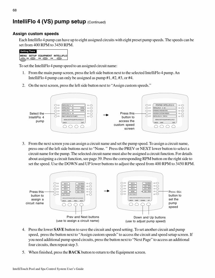
IntelliTouch Pool and Spa Control System User’s Guide
68
IntelliFlo 4 (VS) pump setup (Continued)
Assign custom speedsEach Intelliflo 4 pump can have up to eight assigned circuits with eight preset pump speeds. The speeds can beset from 400 RPM to 3450 RPM.
To set the IntelliFlo 4 pump speed to an assigned circuit name:
1. From the main pump screen, press the left side button next to the selected IntelliFlo 4 pump. AnIntelliFlo 4 pump can only be assigned as pump #1, #2, #3, or #4.
2. On the next screen, press the left side button next to “Assign custom speeds.”
3. From the next screen you can assign a circuit name and set the pump speed. To assign a circuit name,press one of the left side buttons next to “None. ” Press the PREV or NEXT lower button to select acircuit name for the pump. The selected circuit name must also be assigned a circuit function. For detailsabout assigning a circuit function, see page 39. Press the corresponding RPM button on the right side toset the speed. Use the DOWN and UP lower buttons to adjust the speed from 400 RPM to 3450 RPM.
4. Press the lower SAVE button to save the circuit and speed setting. To set another circuit and pumpspeed, press the button next to “Assign custom speeds” to access the circuit and speed setup screen. Ifyou need additional pump speed circuits, press the button next to “Next Page” to access an additionalfour circuits, then repeat step 3.
5. When finished, press the BACK button to return to the Equipment screen.
MENU SETUP EQUIPMENT INTELLIFLO
Getting There
MENU/SETP/EQUIP/INTELLIFLO/ASSIGN
BACK NEXT
AUX 5 1500 RPM
AUX 6 2350 RPM
NONE 1000 RPM
NEXT PAGE
AUX 4 750 RPM
SAVE PREV
MENU/SETP/EQUIP/INTELLIFLO/ASSIGN
BACK UP
AUX 5 1500 RPM
AUX 6 2350 RPM
NONE 1000 RPM
NEXT PAGE
AUX 4 750 RPM
SAVE DOWN
Press thisbutton toassign a
circuit name
Press thisbutton toset thepumpspeed
Prev and Next buttons(use to assign a circuit name)
Down and Up buttons(use to adjust pump speed)
MENU/SETP/EQUIP/IFLO/SELECT
BACK EXIT
INTELLIFLO #2 NONE
NEXT GROUP OF PUMPS
INTELLIFLO 4 #1
INTELLIFLO 4 #4
INTELLIFLO #3 NONE
MENU/SETP/EQUIP/INTELLIFLO
BACK EXIT
PENTAIR INTELLIFLO 4
INTELLIFLO 4 #4
ASSIGN CUSTOM SPEEDS
INTELLIFLO 4 STATUS
SAVE
PRIMING PARAMETERS
Select theIntelliFlo 4
pump
Press thisbutton to
access thecustom speed
screen
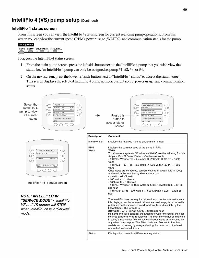
69
IntelliTouch Pool and Spa Control System User’s Guide
IntelliFlo 4 (VS) pump setup (Continued)
IntelliFlo 4 status screenFrom this screen you can view the IntelliFlo 4 status screen for current real-time pump operations. From thisscreen you can view the current speed (RPM), power usage (WATTS), and communication status for the pump.
To access the IntelliFlo 4 status screen:
1. From the main pump screen, press the left side button next to the IntelliFlo 4 pump that you wish view thestatus for. An IntelliFlo 4 pump can only be assigned as pump #1, #2, #3, or #4.
2. On the next screen, press the lower left side button next to “IntelliFlo 4 status” to access the status screen.This screen displays the selected IntelliFlo 4 pump number, current speed, power usage, and communicationstatus.
MENU SETUP EQUIPMENT INTELLIFLO
Getting There
BACK EXIT
PENTAIR INTELLIFLO 4
INTELLIFLO 4 #1
125 RPM 50 WATTS
STATUS NO COMMUNICATION
IntelliFlo 4 (#1) status screen
noitpircseD tnemmoC
1#4olFilletnI rebmuntnemngissapmup4olFilletnIehtsyalpsiD
MPRsttaW
.MPRnipmupehtfodeepstnerrucehtsyalpsiDsttaW
:alumrofgniwollofehtesu”sttaWsuounitnoC“s’metsysaetaluclacoTsttaWsuounitnoC=rotcaFrewoPXstloVXspmA
2351=FP09.X)tloV032(Xspma4.7=olFrepsihW+EPH1-sttaw
0061=FP78.X)tloV032(Xspma0.8=orP–E–xaMPH1-sttaw
)0001siolik(sttawolikotsttawtrevnoc,detupmocerasttawecnO.tsocruoh/ttawolikybrebmunsihtylpitlumdna
ttawoliK10.=ttaw1-ttawoliK1.=sttaw001-ttawoliK1=sttaw0001-
221.$=80.$xttawoliK235.1rosttaw2351olFrepsihW+EPH1-ruohrep
rep821.$=80.$xttawoliK006.1rosttaw0061orP-E-xaMPH1-ruoh
ecnissttawsuounitnocrofnoitaluclaceriuqertonseodolFilletnIehTsttawehtekatylpmistsuJ.sedomllanineercsehtnodeyalpsidsiti
ehtybylpitlumdna,sttawolikottrevnoc,neercsehtnodehsilbup:sialumrofehT.ruohttawolik
ruohrep610.$=80.$Xttawolik012.=sttaw012tsocehtrofdevomretawfotnuomaehtredisnocoslaotrebmemeRdehctamebtonnacolFilletnIehT.)ycneiciffEeriWotretaW(derrucni
ybdeepsynatasttawsuounitnocsusrevwolfrofyrtsudnis’yadotnirehtruflortnocwolfdnaedomretliFehT.loopnipmuprehtoyna
tsaelehtodotpmupehtgniwollasyawlaybgnivastsocnistsissa.semitllatakrowfotnuoma
sutatS sutatsgnitarepoolFilletnItnerrucehtsyalpsiD
Press thisbutton to
access statusscreen
MENU/SETP/EQUIP/IFLO/SELECT
BACK EXIT
INTELLIFLO #2 NONE
NEXT GROUP OF PUMPS
INTELLIFLO 4 #1
INTELLIFLO 4 #4
INTELLIFLO #3 NONE
MENU/SETP/EQUIP/INTELLIFLO
BACK EXIT
PENTAIR INTELLIFLO 4
INTELLIFLO 4 #4
ASSIGN CUSTOM SPEEDS
INTELLIFLO 4 STATUS
SAVE
PRIMING PARAMETERS
Select theIntelliFlo 4
pump to viewits current
status
NOTE: INTELLIFLO IN“SERVICE MODE” - IntelliFloVF and VS pumps will STOPwhen IntelliTouch is in ‘Service”mode.

IntelliTouch Pool and Spa Control System User’s Guide
70
Setting up a ThermalFlo Heat Pump
ThermalFlo screenFrom the ThermalFlo screen you can view the current ThermalFlo operation status, and set the unit to operatewith for heating only, cooling only, or both heating and cooling if the unit is reversible. Connection fromThermalFlo to IntelliTouch is via a COM PORT on the Personality circuit board. See page 107 for ThermalFloto IntelliTouch COM port wiring information. The ThermalFlo must be set to default ADDRESS 1. OneThermalFlo unit can be connected to IntelliTouch.
Operating ThermalFloIf the ThermalFlo is reversible, and cooling is selected, an option heat control is displayed in the HEAT screenbelow the pool heat settings labeled as POOL MAX. This setting allows you to set the maximum heattemperature setting for the pool before the ThermalFlo cooling begins.
To access the ThermalFlo screen:
1. From the EQUIPMENT screen, press the left side button next THERMALFLO.
2. From the next screen, press the left or right side button next to THERMALFLO PRESENT,THERMALFLO HEATING (use heating only), THERMALFLO COOLING (If a reversible unit, use thecooling feature, or just cooling only) to set the options.
MENU SETUP EQUIPMENT THERMALFLO
Getting There
MENU / SETUP /EQUIP
BACK EXIT
CHLORINATOR
PRIORITY
INTELLIFLO
SOLAR
2-SPEED PMP
PUMP DELAYS
SPA OPTIONS
DEGREES C/F
THERMALFLO
MENU/SETP/EQUIPMENT/THERMALFLO
BACK NEXT
THERMALFLO PRESENT YES
THERMALFLO HEATING YES
THERMALFLO COOLING YES
OPERATION NORMAL
THERMALFLO unit present (Yes/No)
THERMALFLO cooling (Yes/No) View current THERMALFLO status
THERMALFLO heating (Yes/No)
SPA
DOWN UPPOOL MAX 100
HEATER
Decrease temperaturefor ThermalFlo
Increase temperature for ThermalFlo
THERMALFLO heat pump heat setting
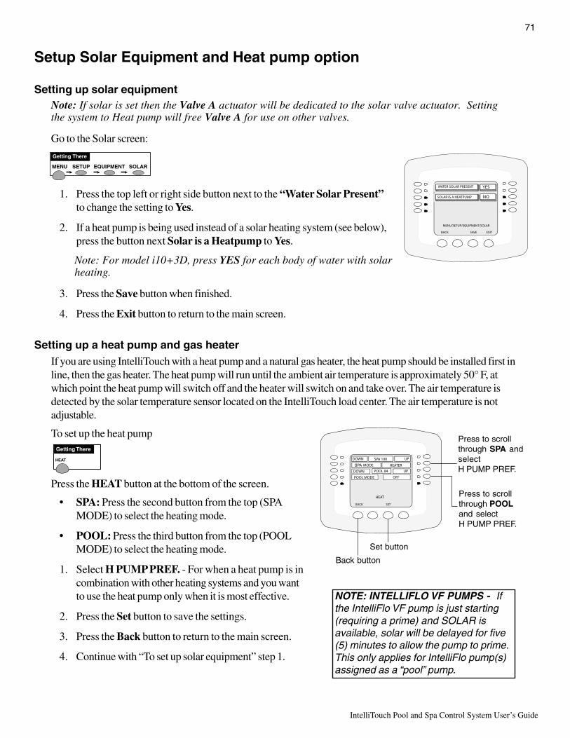
71
IntelliTouch Pool and Spa Control System User’s Guide
MENU SETUP EQUIPMENT SOLAR
Getting There
Setup Solar Equipment and Heat pump option
Setting up solar equipmentNote: If solar is set then the Valve A actuator will be dedicated to the solar valve actuator. Settingthe system to Heat pump will free Valve A for use on other valves.
Go to the Solar screen:
1. Press the top left or right side button next to the “Water Solar Present”to change the setting to Yes.
2. If a heat pump is being used instead of a solar heating system (see below),press the button next Solar is a Heatpump to Yes.
Note: For model i10+3D, press YES for each body of water with solarheating.
3. Press the Save button when finished.
4. Press the Exit button to return to the main screen.
Setting up a heat pump and gas heaterIf you are using IntelliTouch with a heat pump and a natural gas heater, the heat pump should be installed first inline, then the gas heater. The heat pump will run until the ambient air temperature is approximately 50° F, atwhich point the heat pump will switch off and the heater will switch on and take over. The air temperature isdetected by the solar temperature sensor located on the IntelliTouch load center. The air temperature is notadjustable.
To set up the heat pump
Press the HEAT button at the bottom of the screen.
• SPA: Press the second button from the top (SPAMODE) to select the heating mode.
• POOL: Press the third button from the top (POOLMODE) to select the heating mode.
1. Select H PUMP PREF. - For when a heat pump is incombination with other heating systems and you wantto use the heat pump only when it is most effective.
2. Press the Set button to save the settings.
3. Press the Back button to return to the main screen.
4. Continue with “To set up solar equipment” step 1.
HEAT
Getting There
SPA
Press to scrollthrough SPA andselectH PUMP PREF.
Press to scrollthrough POOLand selectH PUMP PREF.
Back button
Set button
NOTE: INTELLIFLO VF PUMPS - Ifthe IntelliFlo VF pump is just starting(requiring a prime) and SOLAR isavailable, solar will be delayed for five(5) minutes to allow the pump to prime.This only applies for IntelliFlo pump(s)assigned as a “pool” pump.

IntelliTouch Pool and Spa Control System User’s Guide
72
MENU/SETUP/EQUIPMENT/PUMP DELAYS
YES
DELAY FOR VALVES YES
Setting up a 2-Speed PumpEquipment circuits displayed on this screen will automatically switch a two speed filter pump to high speedwhen these circuits are switched on. For example, the filter pump will switch from low speed to high speedwhenever the JETS or CLEANER circuit is switched on.
Go to the 2-Speed Pump screen to select your choice of heat options to force the pump to high speed:
1. Press the button next to None. A small arrow is pointing to the select circuit name. “NONE” indicates thatthe pump circuit has not been selected.
2. Use the Up and Down buttons at the bottom of the screen toscroll through the previously assigned names to add anothercircuit for switching filter pump to high speed. After you havefound the desired circuit. To add another circuit, repeat step 1,or Press the Save button. A “FEATURE” circuit can be usedto switch the pump from low speed to high speed(see page 76).
3. Press the Save button.
4. Press the Exit button to return to the main screen.
Note: With a dual equipment system i10+3D, the left columncontrols the spa pump and the right column controls the poolpump.
Delay for Valves and Pumps (Heater Cool-Down Cycle)
Go to the Pump Delays screen.
1. Press the button next to Master Spa/Pool. Press the left orright side button change the setting to Yes. Note: PentairWater Pool and Spa heaters do not require this feature.
2. Press the button next to Delay For Valves. Press the left orright side button change the setting to Yes.
3. Press the Save button.
4. Press the Exit button to return to the main screen.
MENU SETUP EQUIPMENT 2-SPEED PMP
Getting There
MENU SETUP PUMP DELAYSEQUIPMENT
Getting There

73
IntelliTouch Pool and Spa Control System User’s Guide
Delay Cancel FeatureFor convenience, on a one time basis, the DELAY CANCEL feature will cancel the following safety delayswhich can be set up in the IntelliTouch system. Please note there is generally not a need to cancel any of thesedelays except for servicing or testing the system.
• Heater Cool-Down Delay Cancel: Shuts Filter Pump off immediately.
• 2-Speed Filter Pump 5 minute START on HIGH SPEED Delay Cancel: Shifts pump to low speed.
• Automatic Pool Cleaner START Delay: Starts Cleaner Pump immediately. Normally there is a delay inwhich the filter pump first runs for 5 minutes before the cleaner pump starts.
• Automatic Pool Cleaner-SOLAR Delay: Allows Cleaner Pump to run even though solar delay has shut itoff for 5 minutes.
About the Heater Cool-down Cycle and Delay Cancel
Some heaters require a cool-down cycle before being turned off. This can be accomplished with a SET UPprocedure in the IntelliTouch system which runs the filter pump an additional ten minutes to dissipate residualheat built up inside the heater combustion chamber. The DELAY CANCEL feature is mainly for use by servicetechnicians when they want to shut the filter pump off immediately, and know the heater has not been running.
IMPORTANT: Heaters manufactured by Pentair Water Pool and Spa do not require this cool-down periodand do not need the delay to be set up.
To cancel a safety delay:
Go to Delay Cancel Screen
1. Press the button next to DELAY CANCEL. Equipment isswitched off and ready to be serviced.
2. Press the Back button when finished. The system delay isdisabled and the system is returned to normal operating mode.
MENU DELAY CANCEL
Getting There
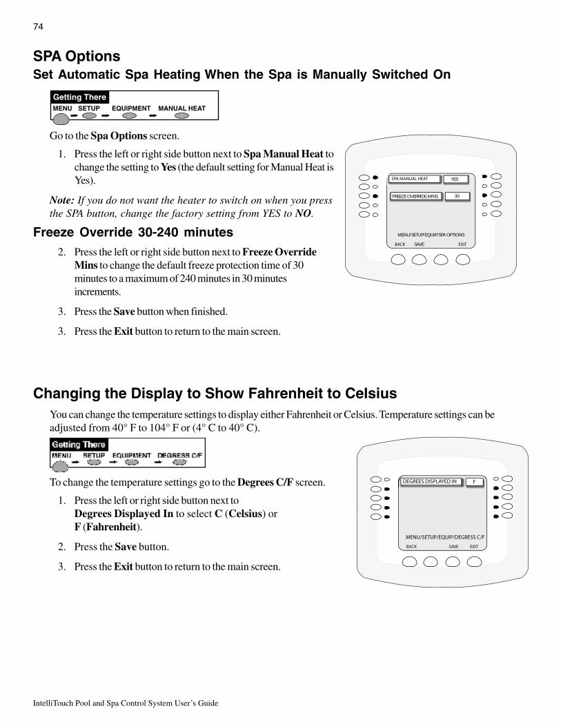
IntelliTouch Pool and Spa Control System User’s Guide
74
SPA OptionsSet Automatic Spa Heating When the Spa is Manually Switched On
Go to the Spa Options screen.
1. Press the left or right side button next to Spa Manual Heat tochange the setting to Yes (the default setting for Manual Heat isYes).
Note: If you do not want the heater to switch on when you pressthe SPA button, change the factory setting from YES to NO.
Freeze Override 30-240 minutes2. Press the left or right side button next to Freeze Override
Mins to change the default freeze protection time of 30minutes to a maximum of 240 minutes in 30 minutesincrements.
3. Press the Save button when finished.
3. Press the Exit button to return to the main screen.
Changing the Display to Show Fahrenheit to CelsiusYou can change the temperature settings to display either Fahrenheit or Celsius. Temperature settings can beadjusted from 40° F to 104° F or (4° C to 40° C).
To change the temperature settings go to the Degrees C/F screen.
1. Press the left or right side button next toDegrees Displayed In to select C (Celsius) orF (Fahrenheit).
2. Press the Save button.
3. Press the Exit button to return to the main screen.
MENU SETUP MANUAL HEATEQUIPMENT
Getting There
MENU/SETUP/EQUIP/SPA OPTIONS
SAVE
YES
30FREEZE OVERRIDE MINS

75
IntelliTouch Pool and Spa Control System User’s Guide
Configuring Valve Actuators (Controlled by AUX or Feature Circuit)All IntelliTouch systems can drive two auxiliary valve actuators (A and B) for applications such as solar heatingand water features. With the addition of the Valve Module (P/N 520285), installed in the Load Center orPower Center, the system will accommodate up to three additional actuators (C, D, and E). An AUX circuit orFEATURE circuit can control auxiliary valve actuators. By using Feature circuits to control valve actuators, youcan conserve your AUX circuits for high voltage relays for controlling pumps and lights. Use Macros to couplevalve actuators with AUX circuits for specific applications.
Note: All Personality boards (including i5x and i10x) has two valve outputs A & B. With the addition ofthe Valve Module (P/N 520285) board that connects to the Personality board, three additional valveoperators can be added to the system.
Configuring Valve Actuators
Note: If Expansion Centers are a part of the system, before this screen, you must select which mainLoad Center or Power Center you wish to configure. The Load Center or Power Center numbermatches display number (1 through 4).
Go to the Configure Valves screen.
1. Select the button next to the valve actuator you wish toconfigure. Keep pressing the button until you find the circuitname which you would like to use to control the valve actuator.
Valve A: Resides on the IntelliTouch Personality board. Ifsolar heating is setup AND NOT configured as a heat pump,then this valve is dedicated for controlling the solar heatingvalve actuator.
Valve B: Resides on the IntelliTouch Personality board next toValve A.
Valves C, D, E: Reside on the optional Valve Module boardthat may be plugged into the IntelliTouch Personality board inany Load Center or Power Center.
2. Repeat the above steps for each valve actuator.
3. Press Save when done.
4. Press Exit to return to main screen.
MENU SETUP ADVANCED CONFIGURE VALVES
Getting There

IntelliTouch Pool and Spa Control System User’s Guide
76
Feature CircuitsFeature Circuits provide a way to control equipment which is not controlled by an AUX circuit. Typically AUXcircuits are used for high voltage equipment such as pumps and lights, whereas Feature Circuits are used forvalve actuators. However, Feature Circuits can go beyond this definition, and be used in other creative ways.For example, Feature Circuits may be used to create a Macro circuit in which several other circuits can beswitched on or off with the same button. This is accomplished by first choosing a name for your Macro andassigning that name to a Feature Circuit. There is a limit of 10 Feature Circuits in the system.
• Valve Actuators - Feature Circuits may be assigned for controlling up to five valve actuators per LoadCenter, which requires the installation of the optional Valve Module P/N 520285 that include three actuatorsoutputs (C, D, and E) per Load Center. For more information about configuring valve actuators, refer topage 70.
• 2-Speed Pump - A Feature Circuit may be assigned as a way to turn a 2-speed Filter Pump to high speed.
• Spa Spillway - A Feature Circuit may be assigned to activate the Spa Spillway effect, where in a pool/spacombination, all of the pool water can be diverted to the spa then spill back into the pool.
Assign a Circuit Name to a Feature CircuitNote: When assigning circuit names in the Indoor Control Panel, use the written list of circuit namesand assigned buttons for the Outdoor Control Panel to make sure that they match.
1. Press the button next to the circuit that you wish to assign a name to.A small arrow pointing to the name is displayed.
2. Use the Up and Down buttons to scroll through the list of presetcircuit names (see page 37). If the preset circuit names are notsuitable, you can create a custom name (see page 38). Press the Backbutton twice and select “Create Custom Names” to create a customcircuit name.
3. Press the Save button to save the Feature circuit name and return tothe Feature screen.
4. To add another Feature circuit, press the button next to FEATUREto add another Feature circuit and repeat step 1, 2 and 3.
5. Press the Exit button to return to the main screen.
To view Feature circuits from the main screen: Press the DISPLAYbutton until the Feature circuit screen is displayed. The F icon located inthe middle lower part of the screen indicates that Feature circuits screen isselected.
MENU/SETUP/ADV/AUX/NAME/FEATURE
MENU HEAT LIGHTS DISPLAY
EDGE PUMP
WATER FALL
CLEANERS
F MON 4:32AMAIR TEMP 92˚
ALL LIGHTS
Feature circuits screen

77
IntelliTouch Pool and Spa Control System User’s Guide
Creating a Macro CircuitA Macro circuit allows multiple combined circuits that can be switched on or off from a single button. Forexample, a Macro circuit can be assign to one button to switch on the spa, spa light, fountain, fountain light, andpatio lights. The Macro circuit name (or custom name) can be added to the main list of “IntelliTouch circuitnames” (see page 37). A Macro circuit also has the capability to switch a circuit off. For example, a Macrocircuit named “SPA PARTY,” if you wanted a spa fountain not to be on when spa is on (because it could putcold water in the spa), it can be set up in the Macro to automatically switch off when “SPA PARTY” is switchedon. An “OFF” Macro can also be used to switch any number of lights off with one button.
Note: Macros may not be set as Dimmers although they can turn on light dimming circuits.
To create a macro circuit, go to the CIRCUIT MACRO screen.
Note: To create a Macro, first assign a FEATURE circuit name (see page 73), assign a function to theFeature circuit (see page 39), then go to the Circuit Macro screen and set up the Macro circuit.
1. The already assigned Feature circuits will be displayed on theFeatures screen. Ten (10) Feature circuits can be displayed on thisscreen.
2. Press the button next to the Feature circuit name that will be theMACRO circuit to control other Feature circuits. Press theDISPLAY button to toggle between the Feature circuit screen andthe Display #1 (1) screen.
Macro Lights:
• To switch a circuit ON, press the button next to the circuit name onetime. The light will be on.
• To switch a circuit OFF, press the button next to the circuit name two times. The light blinks on and off.
• To set a circuit to be unaffected by the macro, press the button next to the circuit name three times. The light isoff.
Note: Be careful when you select circuits to switch on. Onemacro circuit can switch on another macro circuit, resultingin the system incorrectly switching on or off.
3. Press the Save button when finished.
4. Press the Exit button to return to the main screen.
DISPLAY EXIT
MENU SETUP CIRCUIT MACROS
Getting There
MENU HEAT LIGHTS DISPLAY
EDGE PUMP CLEANERS
F MON 4:32AMAIR TEMP 92˚
ALL LIGHTS
WATER FALL
CLEANERS
Feature circuits screen
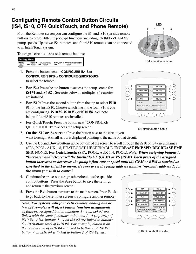
IntelliTouch Pool and Spa Control System User’s Guide
78
iS10 circuit/button setup
Configuring Remote Control Button Circuits(iS4, iS10, QT4 QuickTouch, and Phone Remote)
From the Remotes screen you can configure the iS4 and iS10 spa-side remotebuttons to control different pool/spa functions, including IntelliFlo VF and VSpump speeds. Up to two iS4 remotes, and four iS10 remotes can be connectedto an IntelliTouch system.
To assign a circuits to spa-side remote buttons:
1. Press the button next to CONFIGURE iS4’S orCONFIGURE iS10’S or CONFIGURE QUICKTOUCHto select the remote.
• For iS4: Press the top button to access the setup screen foriS4 #1 and iS4 #2 . See note below if multiple iS4 remotesare installed.
• For iS10: Press the second button from the top to select iS10#1 for the first iS10. Choose which one of the four iS10’s youare configuring, iS10 #2, iS10 #3, or iS10 #4. See notebelow if four iS10 remotes are installed.
• For QuickTouch: Press the button next “CONFIGUREQUICKTOUCH” to access the setup screen.
2. On the iS10 or iS4 screen: Press the button next to the circuit youwant to assign. A small arrow is displayed pointing to the name of that circuit.
3. Use the Up and Down buttons at the bottom of the screen to scroll through the iS10 or iS4 circuit names(SPA, POOL, AUX 1-8, HEAT BOOST, HEAT ENABLE, INCREASE PMP SPD, DECREASE PMPSPD, NONE). For QuickTouch: (SPA, POOL, AUX 1-4, POOL). Note: When assigning buttons to“Increase” and “Decrease” the IntelliFlo VF (GPM) or VS (RPM). Each press of the assignedbutton increases or decreases the pump’s flow rate or speed until the GPM or RPM is reached asspecified in the IntelliFlo menu. Be sure to set the pump address number (normally address 1) forthe pump you wish to control.
4. Continue the process to assign other circuits to the spa-sidecontrol buttons. Press the Save button to save the settingsand return to the previous screen.
5. Press the Exit button to return to the main screen. Press Backto go back to the remotes screen to configure another remote.
iS4 circuit/button setup
DEC PMP SPD
INC PMP SPD
iS4 spa side remote
LED
Note: For systems with four iS10 remotes, adding one ortwo iS4 remotes will affect button function assignmentsas follows: Assigned button functions 1 - 4 on iS4 #1 arelinked with the same functions to buttons 1 - 4 (top row) ofiS10 #4. Also, buttons 1 - 4 on iS4 #2 are linked to buttons6 - 10 (bottom row) of iS10 #4. For example, button 6 onthe bottom row of iS10 #4 is linked to button 1 of iS4 #2,button 7 on iS10 #4 is linked to button 2 of iS4 #2, etc.

79
IntelliTouch Pool and Spa Control System User’s Guide
Setting up the Remote Control Telephone FeatureThe remote control telephone feature allows you to switch on a feature by calling the Indoor Control Panel viathe telephone.
You can only use this feature the TELSPA needs to be connected to the Personality board COM port, and thephone line.
The following describes how to switch on your spa remotely. You can also scroll through the list of availablefeatures and set any one of them. This feature can also be used by a macro circuit (see page 77).
To setup the telephone remote control:
Go to the Spa RF and Phone Remotes screen.
1. Press the button next to CONFIGURE MOD-PHONE toaccess the Phone Remote setup screen.
2. Press the top left button next to NONE.
3. Press the Up or Down buttons to scroll through the availablecircuit names until you find the function you would like toassign to the telephone remote. Choose the function you willuse most often, for example SPA allows you to call the systemand switch on spa filtration and heating with one command.
Note: If you are using the remote to turn on your spa, youmust also enable “MANUAL HEAT.” This allows theheater to always switch on whenever the spa is switchedon via the telephone. For more information, see page 69.
4. Press the Save button to save the setting and return to the remotes screen.
5. Press the Exit button.

IntelliTouch Pool and Spa Control System User’s Guide
80
Disable/Enable iS10 and iS4 Spa-Side RemoteThis feature is useful if you wish to disable the use of the Spa-Side Remote. You can enable and disable theSpa-Side Remote with the same button. Each time the button is pressed it toggles between DISABLED orENABLED.
Go to the Spa Side Remote Disable/Enable screen
1. To Disable: Press SPA SIDE REMOTE ENABLED.Screen will immediately respond and display SPA SIDEREMOTE DISABLED. Remote is now off.
To Enable: Press SPA SIDE REMOTE DISABLED.Screen will immediately respond and display SPA SIDEREMOTE ENABLED. Remote is now on.
2. Press the Back button when finished.
MENU SETUP ADVANCED REMOTES
Getting There
Keypad LockIf required, the IntelliTouch indoor control panel and MobileTouchwireless control panel can be passcode protected so that systemsettings and operations cannot be accessed. To access a ‘locked”control panel, the correct previously assigned four digit passcodemust been entered before access is granted.
Go to the KEYPAD LOCK screen
To assign a four digit passcode and enable the Keypad Lockfeature:
1. Press any combination of four digits using the buttons 1-9.2. Press the ENABLE button to enable the Keypad Lock
feature.3. Press the EXIT button to return to the main screen. Providing
the control panel is not active (no buttons pressed), theKeypad Lock feature will be activated in a few minutes.
Clear Button: Press the CLEAR button to erase the previouslyentered four digit passcode. If the Keypad Lock feature is“Enabled,” pressing Clear will erase the previously entered fourdigits and reset the feature to “disabled.”
Enable/Disable button:
Enable: Pressing the ENABLE button after entering the four digitpasscode will enable the Keypad Lock feature.
Disable: Pressing the DISABLE button will disable the Keypad Lock feature while also retaining the previouslyentered four digit passcode.
MENU SETUP KEYPAD LOCKADVANCED
Getting There
BACK SAVE ENABLE EXIT
0
1
2
3
4
5
7
6
8
0
KEYCODE 0000KEYPAD LOCK IS DISABLED
BACK SAVE DISABLE EXIT
0
1
2
3
4
5
7
6
8
0
KEYCODE 4747KEYPAD LOCK IS ENABLED
Keypad Lock ENABLED

81
IntelliTouch Pool and Spa Control System User’s Guide
Section 4Service and Maintenance
Calibrating Temperature SensorsThe IntelliTouch system includes two temperature sensors (10 kΩ) for water and ambient air temperature. Youcan add a third sensor for controlling solar heating systems. Note: The i10+3D system includes three sensors.
Generally, these sensors are accurate and you do not have to calibrate them. However, long plumbing runs andwater features cause temperatures at a body of water to be different from the temperature sensor reading. Youcan manually recalibrate the sensors to adjust for this.
Before you start, you need an accurate all weather thermometer. If you are calibrating the air sensor, wait untilthe sensor is not in direct sunlight. Be sure that the air sensors are located in the shade for accurate freezeprotection.
To calibrate the water and air sensors, go to the Calibrate screen.
For i10+3D systems, you will see Spa Temp, Pool Temp, and Air Temp. Calibrate the spa and pool watertemperatures the same way as described below for the water sensor. If you have an i5+3, i5S+3, i7+3, or i9+3system, there is a water sensor and an air sensor. Make sure to locate the air sensor in the shade for accuratereadings. Make sure to locate the solar sensor in the sun for accurate readings.
To calibrate the water sensor:
1. Switch on the spa or pool filter pump.
2. Place the thermometer in the spa or pool, depending on the system model number. For shared equipment, youonly need to calibrate one body of water.
3. Take an accurate temperature reading.
4. At the Indoor Control Panel, press the buttons next to the Water Temp label to adjust the temperature up ordown. If you have an i10+3D repeat the above for the pool. The i10+3D has three sensors, one each for thespa and poll water and one for the air temperature. For the Solar option there will be one sensor for the poolsolar, and one for the spa solar.
5. Press the Exit button when finished.
To calibrate the air sensor:
1. Place the thermometer next to the air sensor. The sensor is normally located near or under the Load Centeror Power Center enclosure, not inside the enclosure.
2. Take an accurate temperature reading in the shade.
3. At the Indoor Control Panel, press the buttons next to the Air Temp label to adjust the temperature up ordown.
4. Press the Exit button when finished.
MENU SETUP ADVANCED CALIBRATE
Getting There
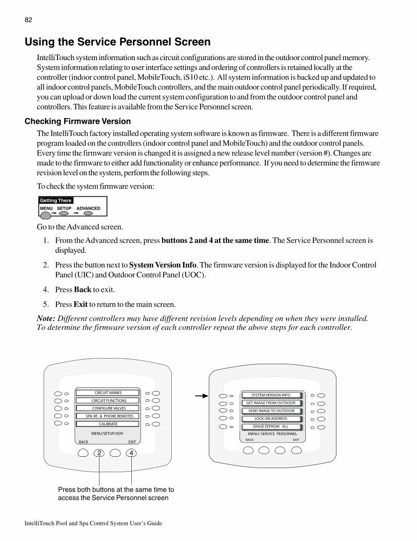
IntelliTouch Pool and Spa Control System User’s Guide
82
Checking Firmware VersionThe IntelliTouch factory installed operating system software is known as firmware. There is a different firmwareprogram loaded on the controllers (indoor control panel and MobileTouch) and the outdoor control panels.Every time the firmware version is changed it is assigned a new release level number (version #). Changes aremade to the firmware to either add functionality or enhance performance. If you need to determine the firmwarerevision level on the system, perform the following steps.
To check the system firmware version:
Go to the Advanced screen.
1. From the Advanced screen, press buttons 2 and 4 at the same time. The Service Personnel screen isdisplayed.
2. Press the button next to System Version Info. The firmware version is displayed for the Indoor ControlPanel (UIC) and Outdoor Control Panel (UOC).
4. Press Back to exit.
5. Press Exit to return to the main screen.
Note: Different controllers may have different revision levels depending on when they were installed.To determine the firmware version of each controller repeat the above steps for each controller.
Using the Service Personnel ScreenIntelliTouch system information such as circuit configurations are stored in the outdoor control panel memory.System information relating to user interface settings and ordering of controllers is retained locally at thecontroller (indoor control panel, MobileTouch, iS10 etc.). All system information is backed up and updated toall indoor control panels, MobileTouch controllers, and the main outdoor control panel periodically. If required,you can upload or down load the current system configuration to and from the outdoor control panel andcontrollers. This feature is available from the Service Personnel screen.
MENU SETUP ADVANCED
Getting There
SEND IMAGE TO OUTDOOR
MENU/SETUP/ADV
BACK EXIT
CIRCUIT NAMES
CIRCUIT FUNCTIONS
CONFIGURE VALVES
SPA, RF, & PHONE REMOTES
CALIBRATE
Press both buttons at the same time toaccess the Service Personnel screen
2 4

83
IntelliTouch Pool and Spa Control System User’s Guide
Manually Updating Between Indoor and Outdoor Control PanelsWhen the IntelliTouch system configuration settings are changed, or a new component is added, the updatedinformation is automatically communicated to all of the control panels. Configuration settings reside in all thecontrollers and the outdoor control panel. This feature provides system backup information in the event one ofthe controllers or control panels is not operational. To update IntelliTouch system configuration informationbetween the indoor and outdoor controllers:
Go to the Advanced screen.
1. From the Advanced screen, press the 2nd. and 4th. buttons at the same time. The Service Personnelscreen is displayed.
2. Press the button next to Get Image from Outdoor to download system configuration data residing in theoutdoor control panel memory to the Indoor or MobileTouch controller.
3. Press the button next to Send Image to Outdoor to upload system configuration data residing in the Indooror MobileTouch controller to the outdoor control panel. A “stopwatch ” icon flashing indicates data is beingtransferred.
4. When the transfer is finished, press Back to exit.
5. Press Exit to return to the main screen.
MENU SETUP ADVANCED
Getting There
SEND IMAGE TO OUTDOOR
MENU/SETUP/ADV
BACK EXIT
CIRCUIT NAMES
CIRCUIT FUNCTIONS
CONFIGURE VALVES
SPA, RF, & PHONE REMOTES
CALIBRATE
Press both buttons at the same time toaccess the Service Personnel screen
Button 2 Button 4

IntelliTouch Pool and Spa Control System User’s Guide
84
Go to the Advanced screen.
5. From the ADVANCED screen, press Buttons 2 and 4 at the sametime. The Service Personnel screen is displayed.
6. Press the left or right side button next to Erase EEPROM All!!7. At the prompt, press the lower button to select YES.
8. Press the ERASE button. The screen will blink a few times thenreturn to the main screen. All system configuration data should nowbe erased and returned to the factory settings.
9. Repeat steps 5-8 for other controllers.
10. At the Outdoor Control Panel press Reset and wait for the system toreturn to “AUTO” mode.
MENU SETUP ADVANCED
Getting There
Erasing the System MemoryIntelliTouch system circuit settings, equipment setup configuration information and screen display information isstored in the main Outdoor Control Panel and the Indoor Control Panel and MobileTouch wireless controlpanel. The current system configuration information automatically downloads from programmed control panelsto update non-programmed control panels in case of accidental memory loss. If a circuit board replacement isnecessary, system programmed memory can be erased and returned to the factory default settings. Once this isdone, the main Outdoor Control Panel (located in the main Load Center or Power Center) will auto-enable allconnected Indoor Control Panels. If there are multiple Expansion Center, iS10’s, or Indoor Control Panels or aMobileTouch control panels, each one of the controllers will need to be manually enabled (see page 26).
To reset to the system to the factory default settings:
CAUTION: This procedure will erase all system settings. All controllers will need to be manuallyenabled again. For more information, see page 26.
1. On the main Outdoor Control Panel (located in the main Load Center or Power Center), press the Resetbutton. The three (3) System Control lights will be lit.
2. Press the number 5 button. The System Control lights will flash OFF then back ON.
3. While the System Control LED lights are ON, press the number 1 button.
4. The System Control LED lights will begin flashing on and off.
1 button 5 button Reset button
SystemControl Lights
MENU/SETUP/ADV
BACK EXIT
CIRCUIT NAMES
CIRCUIT FUNCTIONS
CONFIGURE VALVES
SPA, RF, & PHONE REMOTES
CALIBRATE
2 4
Press both buttons at the sametime to access the Service
Personnel screen

85
IntelliTouch Pool and Spa Control System User’s Guide
System Worksheet OverviewSystem worksheets are provided to help you plan the system at start-up and to keep system records. Makecopies of each system worksheet (page 86 - 91) appropriate for the system. Use a unique one for each LoadCenter or Power Center. Circle the Load Center or Power Center number on the top. Each worksheet isdivided into a Hardwired Connections and a Programmable Settings sections. The Hardwired Connectionssection represents which relays, actuators, and heater have been plugged into the Personality board. Someconnections are mandatory for each system as shown on the work sheet. The Programmable Settings sectionrepresents what functionality the circuit will have and from what Indoor Control Panel and/or MobileTouchcontrol panel they are set from.
In the left-side column, write-in temporary circuit names based on the capabilities you want the system to have.For example: Spillway, Solar Heating, Cherub Fountain, etc. Eventually circuit names will be given to each ofthese capabilities. Although duplicate names can be used, it is best to keep each one unique. Be sure to writethe circuit name on the work sheet that will have the hardwired connection.
Write down on the worksheet which Hardwired Connections (relay or valves) will be activated by the circuit. Itmay be helpful to fill this out at the Load Center or Power Center where the circuits and associated equipmentmay be quickly verified. Remember the following rules to assist in making marks:
• Assign no more than one relay connection to any auxiliary circuit (shown on Display 1 through 4) EXCEPTfor 2-Speed or Feature Circuits.
• Feature Circuits may have multiple relay connections if set up as a Macro.
• Feature Circuits may have multiple valves assigned to them and 2-Speed without being set up as a Macro andwith no other relay connection.
• Valves A-E may be assigned to the same auxiliary circuit as a relay connection.
• If one valve is to be turned on by more than one circuit, then it is suggested to assign a Feature Circuit to justthat valve. That valve and any combination of relay connections may be activated with Macros.
• If SOLAR relay connection is checked and SOLAR is NOT a heat pump, also check Valve A. Valve A maynot then be used with any other circuit. Valve A and the SOLAR relay are activated when solar heating isenabled.
Write down Programmable Settings for each circuit, and what special Circuit Functions, if any, each circuit willhave. Circuit Functions may be assigned to any number of circuits (see page 39). If Spillway is checked, theIntake and Return valves will turn to divert all the pool intake water to be returned to the spa. If “FloorCleaner” is checked, then one or more valves must also be checked to run the floor cleaner multi-port valves. Ifno special function will be assigned check GENERIC.
Write-in any automatically timed programs you want for a circuit. Up to 99 total timed programs may beassigned, but only three are presented on the work sheet. Indicate start times, stop times, countdown time(called “EGG TIMER”), days to be active, and if a color changing light whether or not it should change colorswhen turned on (SMART START).
Finally, indicate what circuits you want to appear on the Indoor Control Panel main screen and what circuits youwant activated by what buttons on a Spa-Side remote. The top buttons of the main screen are dedicated forSpa and Pool modes, however the lower buttons numbered downward may be configured to display anycircuit.
Note: Keep the homeowner worksheets for future reference.

IntelliTouch Pool and Spa Control System User’s Guide
86
WORKSHEET FOR SHARED EQUIPMENT SYSTEMSi5+3, i7+3, i9+3 (Sheet 1 of 2)
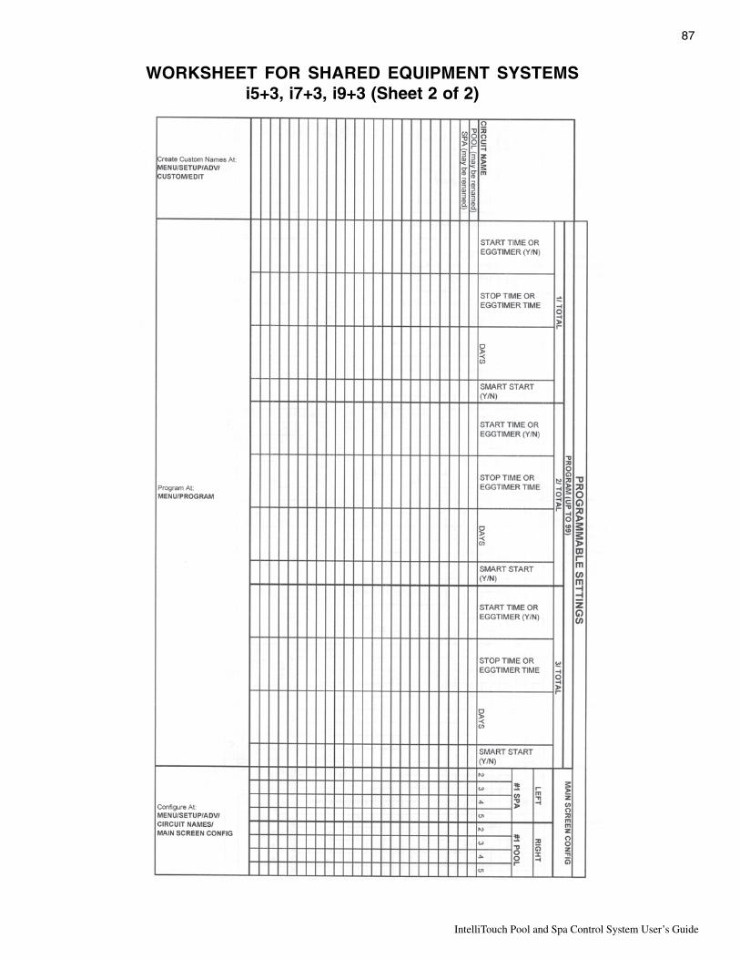
87
IntelliTouch Pool and Spa Control System User’s Guide
WORKSHEET FOR SHARED EQUIPMENT SYSTEMSi5+3, i7+3, i9+3 (Sheet 2 of 2)
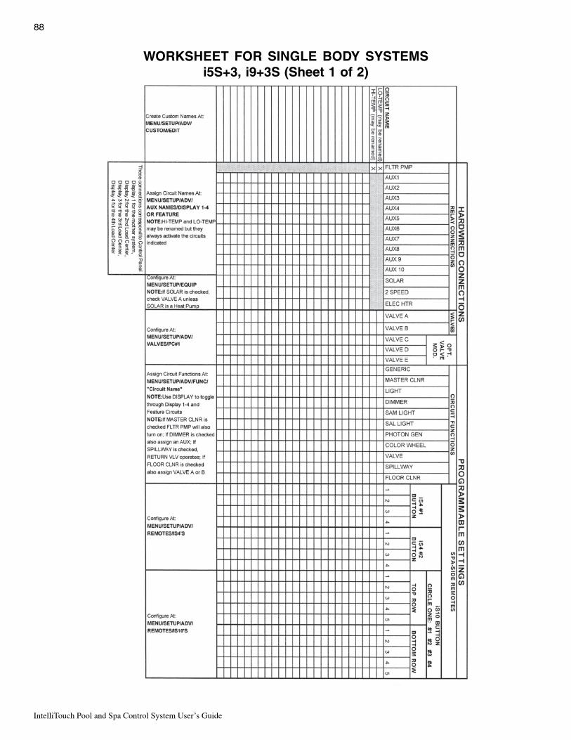
IntelliTouch Pool and Spa Control System User’s Guide
88
WORKSHEET FOR SINGLE BODY SYSTEMSi5S+3, i9+3S (Sheet 1 of 2)

89
IntelliTouch Pool and Spa Control System User’s Guide
WORKSHEET FOR SINGLE BODY SYSTEMSi5S+3, i9+3S (Sheet 2 of 2)

IntelliTouch Pool and Spa Control System User’s Guide
90
WORKSHEET FOR DUAL EQUIPMENT SYSTEMSi10+3D (Sheet 1 of 2)

91
IntelliTouch Pool and Spa Control System User’s Guide
WORKSHEET FOR DUAL EQUIPMENT SYSTEMSi10+3D (Sheet 2 of 2)

IntelliTouch Pool and Spa Control System User’s Guide
92
The Main Outdoor Control PanelThe main Outdoor Control Panel consists of the Personality board mounted onto a motherboard which ishoused inside a Load Center or Power Center. The Outdoor Control Panel includes, control buttons forpumps, filters, and heater, red status lights, and a Reset button. The IntelliTouch Personality board defines thetype of equipment installed. The Outdoor Control Panel can be used to override the Indoor Control Panelfunctions for pool service and for equipment set up. The Outdoor Control Panel is hinged to allow access therear Personality board.
Note: Pressing System Control buttons at any of the Outdoor Control Panels, will affect the entiresystem.
CAUTION: Be sure the High Voltage Cover Panel is in place over the bottom edge of the outdoor controlpanel. DO NOT OPERATE ANY CONTROLS BEFORE READING THE FOLLOWING INFORMATION.
Shared Equipment Systems i5+3, i7+3, i9+3
or the T-Stat setting.

93
IntelliTouch Pool and Spa Control System User’s Guide
Single Body Systems Model i5S+3, i9+3SOperates the same as i5+3, i9+3, except no valve controls.
Dual Body Dual Equipment System Model i10+3DThe i10+3D is designed to operate two sets of pool equipment. Each set of a equipment (Pool or Spa) cancontrol one temperature setting. Operation same as i9+3 except S and P buttons operate independent filterpumps and the Heater and Solar buttons operate independent heating systems and no valve controls.
Expansion Centers Model i5x, i10xExpansion Centers provide additional valve and auxiliary circuits. They are designed to operate with basesystems: i9+3, i9+3S, i10+3D. The “Auxiliary circuit control capability” buttons operate the same way as on themain base Outdoor Control Panel.

IntelliTouch Pool and Spa Control System User’s Guide
94
Erasing Outdoor Control Panel Memory (Factory Default)The Outdoor Control Panel programmed memory can be erased and returned to the factory default settings.System information such as feature circuit configuration, operation and display is retained at the main LoadCenter Outdoor Control Panel and all Indoor Control Panels and MobileTouch controllers. If the memory iserased in the main Outdoor Control Panel (located in the Load Center or Power Center), system informationretained in the Indoor Control Panel or MobileTouch is automatically downloaded. This feature is important incase of accidental memory loss and to ease board replacement. If there are multiple Expansion Center, iS10Spa-Side remotes, or Indoor Control Panels, each one of the controllers will need to be manually enabled (seepages 26 and 27 for details). For instructions about erasing system memory from both the Outdoor ControlPanel and Indoor Control Panel, refer to “Erasing the System Memory,” page 84.
To reset to the factory default settings:
1. On the Outdoor Control Panel, press the RESET button.
2. The three red System Control LEDs are lit for about ten seconds.
3. While the red LEDs are lit, press one of the following buttons
• For models i5+3, i7+3, i9+3, i5S+3, i9+3S, and i10+3D, press button 5.
• For models i5x, i10x, press button 7.
4. The System Control LEDs will switch off then on completing a normal system restart. Wait until the systemhas returned to “AUTO” and “POOL” modes before resuming operation.
Main Outdoor Control Panel (Located in the Load Center or Power Center)
LEDs (System Control)
Reset button5 button(i5+3, i7+3, i9+3,
i5S+3, i9+3S,i10+3D)
7 button(i5, i10x)

95
IntelliTouch Pool and Spa Control System User’s Guide
Section 5Toubleshooting
System Start-UpThe following information describes a basic system start-up procedure. Before switching on the power to theIntelliTouch load center, first affix the auxiliary relay labels to the appropriate buttons on the Outdoor ControlPanel. If necessary, write the function on the control panel.
Check ElectronicsCheck that the following plugs are seated correctly on the Personality board. For connector locations, refer tothe System Wiring Diagrams on page 107 and 108.
• Relay connectors - FLTR PUMP - AUX1 - AUX8• Temperature sensors connectors - WATER, SOLAR, AIR
• Transformer wire harness - J2• Heater control connector - ELEC HTR or screw terminals
System TestThe following describes how to test the Outdoor Control Panel to activate the heater, valves and pumps. Thistest assumes that all system equipment has been properly installed and connected to the Load Center andPower Center.
Testing Valve Actuators and Pumps:
Use the following steps to test the valve actuators (CVA24T - P/N 263045) for proper rotation. For OutdoorControl Panel System i5+3, i7+3, i9+3 (shared equipment).
To test the valve actuators and pump:
1. Power up the load center. Press the SYSTEM CONTROL button on the Outdoor Control Panel until theSERVICE LED light is on.
3. Press the V (Valve) button to select POOL.4. Press the F (Filter Pump) button to activate the filter pump. Water will be removed from the pool and
returned to the pool. The bypass valve will allow some water to fall from the spa back to the pool.
5. Set both valve actuators (CVA24T - P/N 263045) for suction and return. Use the toggle switch on therear of the CVA-24 to withdraw and return water from the pool.
Note: With the filter pump operating, if water is not being removed and returned to the pool, it may benecessary to check the plugs on the Personality board and the toggle switches on the valve actuators.

IntelliTouch Pool and Spa Control System User’s Guide
96
TroubleshootingThis section provides information to help you resolve any problems that may occur during installing or using theIntelliTouch system. If by following the recommended actions you are still unable to resolve the problems pleasecontact Technical Support, see page vii.
Frequently Asked Questions (FAQ)
What does a ‘+3’ IntelliTouch system mean?The first number of a “System Personality” indicates the number of high voltage (auxiliary) circuits availableincluding the filter pump. The ‘+3’ indicates the capability of operating additional equipment without using uphigh voltage circuits. Typically this refers to spillway functionality, valve control (see page 75), and featurecircuits (see page 76). A ‘+3’ system also offers moving colored lights, and the ability to create Feature andMacro circuits.
How Do I Setup/Configure/Program the 2-Speed Pump?Two-speed pumps operate using two relays and one or more circuits with the IntelliTouch system. The firstrelay turns the pump on or off. Assuming this is the filter pump and depending on the system personality, thiscircuit is controlled by the Pool, Spa, high temp, or low temp circuits or any other circuit that may be tied to thefilter pump (such as circuits with freeze protection, etc.). The second relay turns the pump from low speed tohigh speed. The default condition is low speed, but up to 10 circuits may be assigned to trigger the pump tohigh speed. Note: These 10 circuits do NOT turn the pump on.
To configure a two-speed pump relay, refer to “Setting Up a 2-Speed Pump,” page 72. For relay location andwiring, see pages 107 and 108. The 2-Speed pump relay is plugged into the 2-SPD output on the Personalityboard. A circuits must be assigned to switch from low to high speed.
Can I turn the Heater On and Change the temperature from the Spa?The heater may be turned on from the spa using one of two hard wired Spa-Side remote (iS4 or iS10) or bywireless remote controls (MobileTouch or QuickTouch). Only the iS10 or wireless controllers can change thetemperature from the spa location.
How do I get Solar to switch on?The system must first be told that solar heat is installed. Go to the Solar equipment screen (Menu > Setup >Equipment > Solar) and press the YES button to tell the system solar is present. Note: Do not set solar as aheat pump. Then the heating method must be selected for each body of water. Many options are availablethrough the Heat screen (see page 68).

97
IntelliTouch Pool and Spa Control System User’s Guide
What are Color Swim and Color Set?Color Swim: Allows any combination of up to twelve SAm, SAL, IntelliBrite, and/or FIBERworks lightingcircuits to be preset to transition through colors in sequence, giving the appearance of the colors swimmingacross the water. The delay in sequencing each light can be adjusted to customize the display for your pool. Formore information see “Setting Up Lighting Options,” page 42.
Color Set: Allows any combination of up to twelve SAm, SAL, IntelliBrite, and/or FIBERworks lightingcircuits to be preset to specific colors, such as red, white, and blue for the Fourth of July or red and green forChristmas.
How do I get SAm/SAL/PG2000 to Synchronize?There are many ways to configure color changing lights to synchronize on the same colors. The first step is toassign all color changing light circuits a circuit function such as SAm, SAL, Photon Generator, or Color Wheel.Refer to “Assign Circuit Functions and Freeze Protection,” page 39.
To manually synchronize the lights, use the Sync button on the Lights screen. Refer to page 13 for details abouthow to setup the circuits to appear on the Lights Screen.
Light circuits may be controlled to switch on at a particular time and synchronize automatically. This may bedone by using the Smart Start functionality in the Program Screen. See page 15 for programming details.
Can I copy a standard configuration to all the systems I install?Yes you can but only if you maintain a standard system configuration on a system in your headquarters. AnIndoor Control Panel with a properly wired four conductor patch cable may be used to accomplish this.
CAUTION - Do NOT use the Service Panel. This accessory auto erases every time power is removed. It is for on-site work only.
1. Plug the Indoor Control Panel into a COM port on the Personality board of dedicated system at headquarters.
2. One of several things may happen at this point:
• The Indoor Control Panel may automatically download the system configuration if its own memory waserased.
• You may be prompted to update system personality, see page 83.• You may be prompted to select Indoor or Outdoor memory. Always Select Outdoor or you will write over
your dedicated set up.• You may have to force a download to the system.
3. This same controller may then be taken to the job-site to configure the system. Switch off the system power.Open Load Center or Power Center front door, remove the two retaining screws and fold down the OutdoorControl Panel.
4. Plug in the Indoor Control Panel to one of the COM ports from headquarters.
CAUTION - Be sure to check that the wiring is matching both ends before turning system power back on. Crossed wiring may permanently damage the system.
5. The procedure is identical to Step 2 above. Plug into the COM port on the Personality board in the LoadCenter or Power Center. Again, several different things may happen. Check all the relevant sections to avoidany problems.

IntelliTouch Pool and Spa Control System User’s Guide
98
Fixing mismatched system personalitiesSometimes the Indoor Control Panel or MobileTouch will have communication problems with the OutdoorControl Panel or with each other. The possible cause may be as follows:
1. A controller is added or replaced. Accessory and replacement controllers leave the factory identified as ani9+3 system.
2. A controller’s memory is erased while unplugged from the system.
3. The IntelliTouch system personality (i9+3, i10+3D etc.) was changed.
If this problem occurs a mismatched system personality message screen may be displayed. Press the NEXTbutton to update the controller to match the system personality. If you do not want to update the controller(most likely because you are service person using the controller for another purpose) then press IGNORE.
Indoor Control Panel and Outdoor Control Panel Connection ProblemSystem information relating to circuit configuration, operation and display is retained at the main Load CenterOutdoor Control Panel and all Indoor Control Panels and MobileTouch. System information is automaticallydownloads from programmed components to non-programmed components in case of accidental memory lossand to ease board replacement.
If for some reason the controller and outdoor control panel both have user settings that conflict with each otherthen this must be reconciled. Such occasions include but are not limited to:
1. The MobileTouch wireless controller made changes while the system power was down.
2. A service company made a special upgrade and installed it on an existing system.
If the Service Personnel screen appears, choose Indoor to use the controller settings and Outdoor to use theOutdoor Control Panel settings. Refer to page 82 for more information.
MobileTouch Temperature Readout Not Accurate (20 to 30 Degrees off)Problem: If the MobileTouch wireless controller LCD temperature readout displays an inaccurate reading, itmay be due to wireless signal interference. In this case, the air temperature readout can be correct.
Description: Temperature sensor cables are picking up signal interference.
Solution: To prevent signal transmission interference, ensure that the temperature sensor cables that connect thesensor to the Load Center are not routed near a Florescent lighting fixture (within six (6) inches).

99
IntelliTouch Pool and Spa Control System User’s Guide
System Problem DiagnosisUse the following information to resolve system problems.
Problem: The system works in Service Mode, but Indoor Control Panel fails to operate.
motpmyS esuaCelbissoP noituloS
onsahlenaPlortnoCroodnIon,knalb,neercs(-rewop.gnikrowtonsnottub,sDEL
morfnurgniriwdaBlortnoCroodtuO
draobytilanosreP/lenaProretneCdaoLehtni
retneCrewoP
.snoitcennoclanimretwercsdna,gniriwkcehCesU/etaerC.detrohsronekorberaseriwonerusnE
lenaproodniehttcennocdnaelbactsettrohsaredrogniriwehttcerroCretnecrewopehtotyltcerid
esuacyamsihtsesacemosnI.stinullaneewteblacinhceTtcatnocsruccosihtfI.egamadtnenamrep
tsomsisihT.sBCPtnemecalperroftroppuSroodnIerapsagnisuybdenimretedylevitceffe
lacinhceTtcatnoC.lenaps'namecivreSrorellortnocBCPtnemecalperroftroppuS
seriw(yltcerrocnideriW)redrotcerrocniton
emosnI.stinullaneewtebredrogniriwehttcerroCsihtfI.egamadtnenamrepesuacyamsihtsesac
.sBCPtnemecalperroftroppushcettcatnocsrucco
roodnIevitcefeDlenaPlortnoC
erapsagnisuybdenimretedylevitceffetsomsisihTtcatnoC.lenaps'namecivresrorellortnocroodnI
BCPtnemecalperroftroppushcet
tub,pusthgiLlenaproodnIehT.yltcerrocetarepootsliaf
tnempiuqenruttonlliwtinusmetiemosnrutyamro,ffo/no
tonyamdnaffotontub,noroodninosnottubraensDEL
.lenap
gniriw/elbaCevitcefeD yfireV elbac .nekorberasnoitcennoconerusnidnaehtrednunekorbsieriwasesacemosnI
ruofehtfoseriwretnecowtehT.noitalusni)wolleYdnaneerG(tcepsuseraelbacrotcudnoc
ylevitceffetsomsisihTagnisuybdenimretedrellortnocroodnIeraps.lenaps'namecivresro
troppushcettcatnoCBCPtnemecalperrof
erapsagnisuybdenimretedylevitceffetsomsisihTtcatnoC.lenaps'namecivresrorellortnocroodnI
.BCPtnemecalperroftroppushcet01SI/slenaplortnocelpitlumhtiwsmetsysnI
troppuSlacinhceTllac-tluafenimreted
tonlenaPlortnoCroodnI.gnidnopser
.sserddatcerrocnI nahtsserddatnereffidasahlenaPlortnocroodnIXUAnehtTESERsserP.lenaPlortnocroodtuOeht
kcoldnalenaPlortnoCroodnIehtotoG.nottub1.SSERDDAno

IntelliTouch Pool and Spa Control System User’s Guide
100
Problem: Indoor and Outdoor Control Panels work, but iS4 fails to operate.
motpmyS esuaCelbissoP noituloS
etarepootsliafediSapS4Si.tnempiuqe
silortnoCediSapSniamybdelbasiD
.lenap
.lenaps'namecivresarolenaproodniehtgnisUAPS"sdaernoitcelesehterusnidna'UNEM'sserPEDISAPS"sdaertifI."DELBANEETOMEREDISehtedisebnottubehtsserp"DELBASIDETOMER
.noitcelesehtelggototnoitpo
noitarugifnoctcerrocnIhctiwsottiucricro
evitcefedrotnemngissa.gniriw
sserP.putes4SiyfireVENOHP&,FR,APS/DECNAVDA/PUTES/UNEM'ehterusnI's'4SiERUGIFNOC'tceleS'SETOMER
tiucricdetcepxeehtsahnoitseuqni4Sidesunuotdengissatonsidna,stnemngissa
.stiucric
4SievitcefeD 4SievitcefedecalpeR
emosylnoetarepootsliaf4Sisrehtotub,sehctiwsehtfo
.enifkrow
enonogniriwevitcefeDsdael4Sieromro
evobadebircsedsagniriwyfireV
noitarugifnoctcerrocnIhctiwsottiucricro
.tnemngissa
evobadebircsedsanoitarugifnocyfireV
4SievitcefeD ecalpeR.retemmhO-tloVahtiw4SiyfirevdnatseTsitinufi.troppuSlacinnhceTtcatnoC.4Sievitcefed
.dabllits

101
IntelliTouch Pool and Spa Control System User’s Guide
Problem: Indoor and Outdoor Control Panels work, but iS10 fails to operate.
motpmyS esuaCelbissoP noituloS
etarepootsliafediSapS01Si.tnempiuqe
silortnoCediSapSniamehtmorfdelbasiD
.lenaplortnoc
.lenaps'namecivresarolenaproodniehtgnisUAPS"sdaernoitcelesehterusnedna'UNEM'sserP
EDISAPS"sdaertifI."DELBANEETOMEREDISehtedisebnottubehtsserp"DELBASIDETOMER
.noitcelesehtelggototnoitpo
gniriWevitcefeD sserP.putes01SiyfireVENOHP&,FR,APS/DECNAVDA/PUTES/UNEM'
ehterusnE.s'01SiERUGIFNOC'tceleS'SETOMERtiucricdetcepxeehtsahnoitseuqni01Si
desunuotdengissatonsidna,stnemngissa.stiucric
noitarugifnoctcerrocnIhctiwsottiucricro
.tnemngissa
sserP.putes01SiyfireVENOHP&,FR,APS/DECNAVDA/PUTES/UNEM'
ehterusnE's'01SiERUGIFNOC'tceleS'SETOMERtiucricdetcepxeehtsahnoitseuqni01Si
desunuotdengissatonsidna,stnemngissa.stiucric
yltcerroctonsi01SIdelbane
.01Siehtelbaneyllaunamot08egapeeS
01SievitcefeD lacinnhceTtcatnoC.01SievitcefedecalpeR.troppuS
ylnoetarepootsliaf01Situb,sehctiwsehtfoemos
.enifkrowsrehto
enonogniriwevitcefeDsdael01Sieromro
dna,erarsisihT.evobadebircsedsagniriwyfireVsihtesuacnactahtdaeleriwylnoehtyllamron
.noitcennoCyfireV.eriw'neerG'ehtebdluow
noitarugifnoctcerrocnIhctiwsottiucricro
.tnemngissa
evobadebircsedsanoitarugifnocyfireV
01SievitcefeD .retemmhO-tloVahtiw01SiyfirevdnatseTlacinnhceTtcatnoC.01SievitcefedecalpeR
.dabllitssitinufi.troppuS

IntelliTouch Pool and Spa Control System User’s Guide
102
Problem: The Mobile Control Panel will not work, or will not work dependably.
motpmyS esuaCelbissoP noituloS
otsliafhcuoTeliboMehTrononruttonseodtI.etarepo
.puthgil
degrahctonsiyrettaBdeggulptonsitinuro
.ni
hcuoTeliboMehtotniregrahcerCAehtdehcattA.teltuollawaotnigulpdna
.hcuoTeliboMevitcefeD .troppuSlacinhceTtcatnoC.tinuecalpeR
otsliafhcuoTeliboMehT.etarepo
neebtonsahtinuehT.yltcerrocdelbane
.hcuoTeliboMehtelbaneyllaunamot82egapeeS
ehT-gniriWevitcefeDotdehcattareviecsnarT
roretneCdaoLehttonsiretneCrewoP
.deriwyltcerroc
nekorbrofkcehC.redrogniriwdna,gniriWyfireV.snoitcennocesooldnaseriw
tareviecsnarTevitcefeDroretneCdaoLeht
.retneCrewoP
erareviecsnarTehtnosDELowtehttahtyfireVREWOPdekramDELehT.detcepxesaevitca
KNILdekramDELehT.tilebsyawladluohssdnocesowtyreve.xorppahsalfdluohsYTIVITCAnehwsahcus(noitacinummocsierehtrevenehwro
.hcuoTeliboMehtnonottubasserpuoy
.hcuoTeliboMevitcefeD .troppuSlacinhceTtcatnoC.tinuecalpeR
otsliafhcuoTeliboMehT.ylbadnepedetarepo
ehT-gniriWevitcefeDotdehcattareviecsnarT
toretneCdaoLehttonsiretneCrewoP
.deriwyltcerroc
dluoweriwneergehtylno,llamrondna,erarsisihT.noitcennoCyfireV.melborpsihtesuac
yrevsahhcuoTeliboMehTegnargnitareporoop
mumitponahtsseLehtfonoitacol
detcennocreviecsnarTroretneCdaoLehtot
.retneCrewoP
detcurtsbosselawollaotreviecsnartehtetacoleR.reviecsnarTehtdnahcuoTeliboMehtneewtebhtap
onsiegnarhcuoTeliboMehThtiwneveteef03nahterom
otnoitarepothgisfoenilraelc.reviecsnarTeht
rotinuevitcefeDylekiL.reviecsnarTnekorbroevitcefedlanretniroannetna
.noitcennocannetna
.troppuSlacinhceTtcatnoC

103
IntelliTouch Pool and Spa Control System User’s Guide
Problem: The Quick Touch remote will not work, or will not work dependably.
motpmyS esuaCelbissoP noituloS
nothgiltonseodDELREWOPBCPrevieceReht
daoLhcuoTilletnIretneCrewoProretneC
.rewopevahtonseod
rewopehttahtdnadeilppusgniebsirewoperusnEreviecerehttuohtiwyltcerrocsetareporetnec
.dellatsni
roelbacevitcefeDdaoLehtotnoitcennoc
rewoProretneC.retneC
doognwonkgnisudraobehtfonoitcnufehtyfireV.gniriwllakcehC.teselbac
revieceRevitcefeD.draob
.troppuSlacinhceTtcatnoC
tonseodDELKNILMMOClamronnI.knilbrothgil
taknilblliwDELnoitareposdnoces2yrevetsael
roelbacevitcefeDdaoLehtotnoitcennoc
rewoProretneC.retneC
doognwonkgnisudraobehtfonoitcnufehtyfireV.teselbac
reviecerevitcefeD.draob
.draobreviecerecalpeR
erasehctiwssserddAderugifnocyltcerrocni
sserddaehttahtyfireVehtnosehctiwsdnarettimsnart
reviecerdlehdnahdnatcerroceradraob
.hctam
.deliafsahyrettabrettimsnarT
rettimsnarTecalpeRyrettab
revieceRrorettimsnarTevitcefeD
lacinhceTtcatnoC.troppuS
emostub,snoitcnuftinUro,krowtonodstiucric
tiucrictcerrocniehtetarepo
hcuoTkciuQsinoitarugifnoc
.tcerrocni
sserP.putesTQyfireVENOHP&,FR,APS/DECNAVDA/PUTES/UNEM''HCUOTKCIUQERUGIFNOC'tceleS'SETOMER
tiucricdetcepxeehtsahhcuoTkciuQehterusnEstiucricdesunuotdengissatonsidna,stnemngissa
sliafro,etarepootsliaftinUegnartaylbadnepedetarepo
esionlacirtceleeudnU sahcustnempiuqemorfyawareviecerehtetacoleR.srotomrewolb
snoitcurtsboynamooTrettimsnartehtneewteb
.reviecerdna
.revieceretacoleR
ootsitinurevieceR.dnuorgehtraen
ecnatsidehtezimixamotreviecerehtetacoleR.dnuorgehtdnaannetnareviecerehtneewteb

IntelliTouch Pool and Spa Control System User’s Guide
104
Problem: The Quick Touch remote will not work, or will not work dependably (Continued).
motpmyS esuaCelbissoP noituloS
fforononrutotsmeestinU/resuehttuohtiwstiucric
rettimsnart
siemohybraenAralimisagnitarepo
tinusseleriw
ehtrofedocsserddaetanretlanaatceleSnosehctiwsehtegnahc.e.I.reviecerdnarettimsnart
.gnittesgnihctamtub,etanretlanaotsdraobhtob
snrutylbadnepedtinUecnotub,NOtnempiuqe
seodtigninnursitnempiuqetnempiuqenrutylbadnepedton
yltaergsiegnarro,FFOsitnempiuqenehwdecuder
gninnur
esionlacirtceleeudnUybdecudorpgniebsi
foseceiperomroenoesolcnitnempiuqe
.reviecerehtotytimixorp
sahcustnempiuqemorfyawarevieceRehtetacoleRnoitacolanirevieceRehtetacoleRsrotomrewolb
resuehtaeraehtotsnoitcurtsborewefsedivorptaht.rettimsnartehtsetarepoylnommoc
yltaergsahtub,setarepotinUotderapmocegnardecuder
noitcnufroirp
siyrettaBrettimsnarTgniliaf
yrettabrettimsnarTecalpeR

105
IntelliTouch Pool and Spa Control System User’s Guide
IntelliFlo Alerts and WarningsThe IntelliFlo displays all alarms and warnings on the control panel display. When an alarm or warningcondition exists, the corresponding LED will be lit on the display. All control panel buttons are disabled untilthe alarm or warning is acknowledged with the Enter button. Press the Reset button to clear the alarmonce the fault condition has been resolved. Note: The IntelliFlo pump will not start if the impeller is rotating.The alerts and warnings are:
• Power out failure: The incoming supply voltage is less than 170 VAC. The drive faults to protectitself from over current. The drive contains capacitors that keep it powered up long enough tosave the current run parameters. If power is restored during this process, approximately 20seconds, the drive will not restart until completed.
• Priming error: If the pump is not defined as primed within the "Max Priming Time" it will stop andgenerate a “Priming Alarm” for 10 minutes, then attempt to prime again. The "Max Priming Time"is set by the user on the priming menu as discussed on page 14. If the IntelliFlo cannot primewithin five attempts it will generate a permanent alarm that must be manually reset.
• Overheat alert: If the drive temperature gets above 130 degrees, the IntelliFlo will slowly reducespeed until the over temperature condition clears.
• Anti-freezing: When active, the motor will run at 1000 rpm for 60 minutes. Only active in Filterand Manual modes. Note: The IntelliFlo's internal anti-freeze protection is disabled whenconnected to an IntelliTouch system. Freeze protection is provided by selecting YES at the ONWITH FREEZE portion of the IntelliTouch's appropriate circuit function menu. To re-enable theIntelliFlo's internal anti-freeze protection, the power to the drive must be cycled off then back on.
• Blocked system: Detects a blocked suction line. This alarm resets automatically after 30 secondsand the pump restarts.
• System service soon: Alerts the operator that the pump discharge pressure has reached theClean Filter Pressure as setup in the Filter Menu. The filter status will be displayed as 100%. Theyellow warning LED will be on until a backwash cycle is operated. The IntelliFlo will automaticallyreduce speed as necessary to not exceed the Clean Filter Pressure.
• Over current: Indicated that the drive is overloaded or the motor has an electrical problem. Thedrive will restart 20 seconds after the over current condition clears.
• Over voltage: Indicates excessive supply voltage or an external water source is causing the pumpand motor to rotate thereby generating an excessive voltage on the drives internal DC bus. Thedrive will restart 20 seconds after the over voltage condition clears.
Note: For IntelliFlo troubleshooting information, see the IntelliFlo 4 Installation and User’s Guide(P/N 350075).
Suction BlockageWhen something blocks the suction or the pump fully it will shut off immediately (within 1 second). It willalso shut off after a few seconds of dead heading with the same alert. The unit will come back on in 30seconds and ramp up slowly. This function should be tested with all new installations by directing the flow toone suction and covering it with a piece of material other than someone’s hand. This alert is deactivated inManual mode.

IntelliTouch Pool and Spa Control System User’s Guide
106
IntelliFlo 4x160 Warning and Alarm ConditionsThe IntelliFlo 4 alarms and warnings are indicated by flashing LEDs on the control panel. For example, ifa “Drive Temperature” warning occurs, the LED will blink two times, then Off, then blink two times. Thissequence is repeated until the condition is cleared.
• Warning condition: If a warning condition occurs the pump will be continue to run but at areduced speed. The Green LED executes a sequence of blinks to indicate which alarm orwarning has occurred.
• Alarm condition: If an alarm condition occurs the pump will drive stop running. The red LEDflashes continuously to indicate the presence of an alarm. The alarm LEDs will reset when thecondition clears.
For IntelliFlo troubleshooting information, see the IntelliFlo 4x160 Installation and User’s Guide(P/N 357269).
Alarm and warning LED sequence
ehtemitforebmuNknilblliwDEL
mralA noitpircseD noitcA
2 gninraWerutarepmeTevirD erutarepmetevirdevissecxE sahnafrotomehterusnE.1.noitalitnevrofaeraetauqeda
.loocotwolladnarotompotS.2
otdeepsrehgihatarotomnuR.3.wolfriagniloocevorpmi
5 mralanwonknU eruliafnortcelE .pmupteserotrewopelcyC.1.evirdecalpeR.2
6 mralAerutarepmeTevirD erutarepmetevirdevissecxE sahnafrotomehterusnE.1.noitalitnevrofaeraetauqeda
otdeepsrehgihatarotomnuR.2.wolfriagniloocevorpmi
7 mralAtuOrewoP wolegatlovylppuS .egatlovylppusreporperusnE
8 mralAtnerrucrevO tnerrucevirdevissecxE lacinahcem/diulfenimaxE.1.daolrevofoecruosrofmetsys
dnarotomezigrene-eD.2.yleerfsnipsrotomfienimreted
.evirdecalpeR.3
9 mralAegatlovrevO ssubevirdnoegatlovevissecxE sdeepsneewtebgnihctiwsdipaR.1segatlovevissecxeesuacnac
.ssubCDs'evirdehtno.egatlovylppusreporperusnE.2
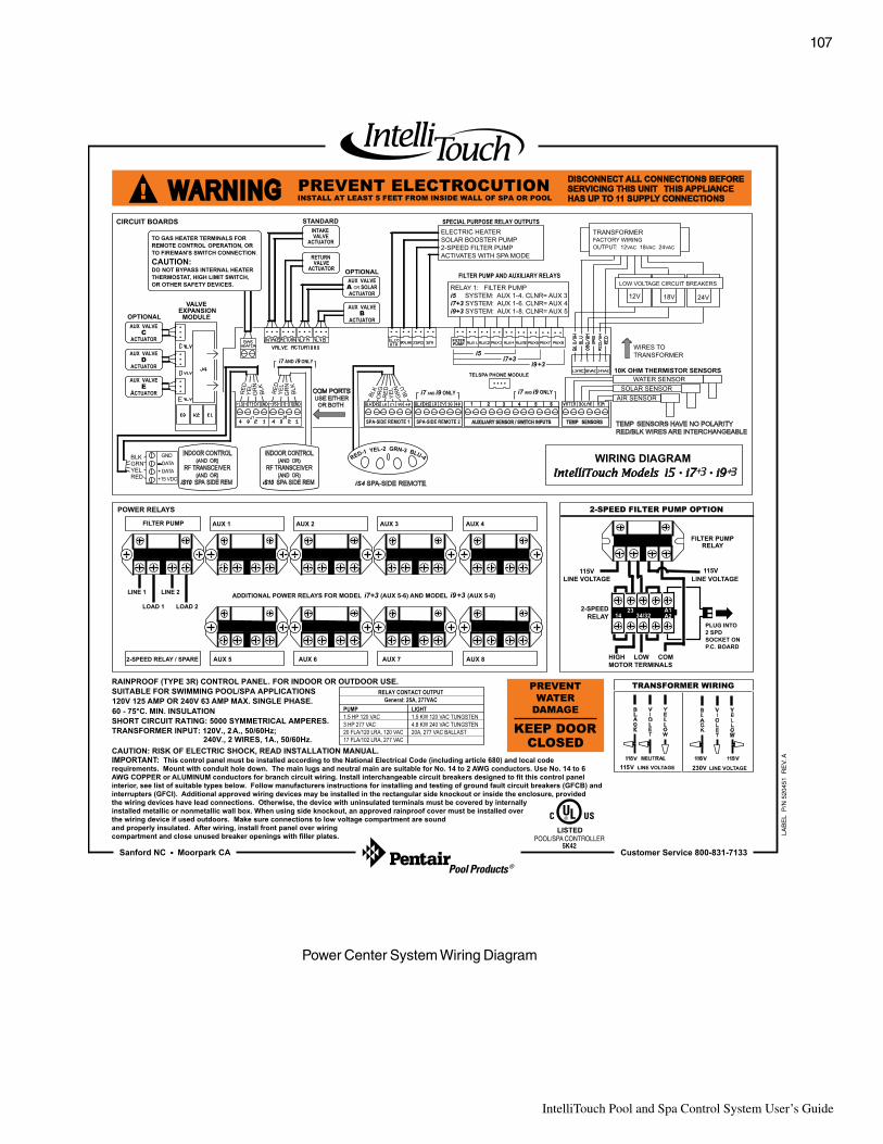
107
IntelliTouch Pool and Spa Control System User’s Guide
Power Center System Wiring Diagram
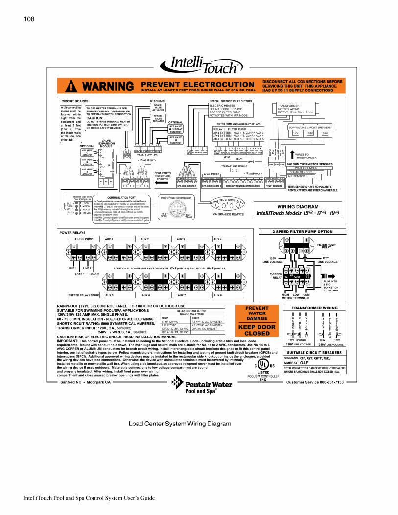
IntelliTouch Pool and Spa Control System User’s Guide
108
Load Center System Wiring Diagram
QP, QT, QPF, QE,QAF

109
IntelliTouch Pool and Spa Control System User’s Guide
Wiring IntelliTouch to a Salt Chlorine GeneratorBe sure to check the wire color and function of the salt chlorine generator before connecting it to theIntelliTouch COM port on the Personality board. See the wiring table below for the pin configuration.
Commonly used salt chlorine generator wiring is shown but you should still verify with the manufacturersdocumentation.
Failure to wire the salt chlorine generator properly can permanently damage the IntelliTouch system or chlorinegenerator.
Wiring Description
tropMOChcuoTilletnInoitcennocrolocgniriw
noipircseD rotareneGenirolhCtlaSsroloceriwdesuylnommoc
)DER(4NIP CDV51+ DER
)WOLLEY(3NIP ATAD+ KCALB
)NEERG(2NIP ATAD- WOLLEY
)KCALB(1NIP DNUORG NEERG
Wiring ThermalFlo to IntelliTouchBe sure to check the ThermalFlo terminal block wire colors and pinouts (located on the back of the Auto Setboard) before connecting it to the IntelliTouch COM port on the Personality board. The See the wiring tablebelow for the pin configuration.
IMPORTANT: On the ThermalFlo AutoSet board ONLY CONNECT PIN 3 (YELLOW) and PIN 2 (GREEN) to theIntelliTouch COM port pins YELLOW and GREEN respectively. Do not connect pin 1 or pin 4 on the AutoSetboard or the IntelliTouch Personality board. These pins are not used.
Wiring Description
eriwtropMOChcuoTilletnIroloc
noipircseD dnarebmunnipolFlamrehTroloceriw
)DER(4NIP )ESUTONOD( CDV51+ )ESUTONOD(4NIP
)WOLLEY(3NIP ATAD+ )WOLLEY(3NIP
)NEERG(2NIP ATAD- )NEERG(2NIP
)KCALB(1NIP )ESUTONOD( DNUORG )ESUTONOD(1NIP

IntelliTouch Pool and Spa Control System User’s Guide
110
GlossaryActuators: Motorized accessory for turning valves and diverting water; model CVA24T.
Color Set: Allows a combination of up to 12 SAm, SAL, IntelliBrite or Fiberworks lighting circuits to be presetto specific colors.
Color Swim: Allows a combination of up to 12 SAm, SAL, IntelliBrite or Fiberworks lighting circuits to bepreset to transition through colors in sequence. This gives the appearance of colors dancing across your water.
Component ID: Unique identifier that tells the system what each component is.
Controller: Indoor Control Panel or MobileTouch wireless controller.
Expansion Kit: A kit that includes additional auxiliaries to an existing Personality Kit. Requires a Load Centeror Power Center for each Expansion Kit.
Feature Circuits: Programmable circuits that may control relays, macros, and/or valve actuators.
Firmware: Factory installed operating system software dedicated for use with the IntelliTouch system; eachtype of control panel has its own firmware and release level.
Freeze Protection: Switches on a circuit if the air temperature drops below 35° F.
High Voltage Compartment: Large lower right compartment of Load Center or Power Center for all highvoltage wiring including circuit breakers, relays, and GFCI.
House Address: Signal that allows Each IntelliTouch system the ability to group all its attached componentsunder a single system identification; prevents the system from confusing its components from components on aneighbor’s system.
ICP: Indoor Control Panel.
Indoor Control Panel: Fourteen button remote controller with LCD (liquid crystal display) is wired to thePersonality board in the Power/Load Center.
iS4: Four function Spa-Side remote. Wall or deck mounted.
iS10: Ten function spa-side remote with temperature changing capability and display. Wall or deck mounted.
Load Center: Metal enclosure with power relays, transformer, and circuit breakers. The Load Center isInstalled prior to Personality Kit installation. Used for distributing power for controlling IntelliTouch Systems.Also known as the “sub-panel.”
Low Voltage Compartment: Top compartment of Load Center or Power Center for all low voltage wiring.
Low Voltage Raceway: Vertical space in the left side of Power/Load Center for low voltage cabling.
Macro: Feature circuit that allows you to combine circuits to activate together.
MobileTouch Controller: Wireless controller for the IntelliTouch Systems with all the functionality of theIndoor Control Panel.
Mud Box: Enclosure to provide mounting features for iS10 spa-side remote that is cast into gunite, concrete,or other spa wall/deck construction.
Outdoor Control Panel: Control panel with flexible hinge installed in upper portion of Load Center or PowerCenter to control IntelliTouch systems.

111
IntelliTouch Pool and Spa Control System User’s Guide
Glossary (Continued)
Personality Board: The circuit board mounted on top of the Outdoor Control Panel motherboard. ThePersonality board defines the system capabilities.
Personality Kit: Set of parts to define the capability of a system. Can include, temperature sensors, actuators,and additional relays, actuators.
Power Center: Same as Load Center with the exception of the circuit breaker base.
Relay Circuits: The circuits that control the relays on the Personality Board. Connectors on top edge of thecircuit board.
Screw Terminal Connector: Removable connector that may attach to circuit board with multiple sockets(anywhere from 2 to 12) to receive wires from controllers and sensors; wires held by screw terminals; multiplewires of a small enough gauge (usually 22 AWG) may be coupled to a single socket of a terminal connector.
Transceiver: Circuit board with attached antenna that can send and receive radio frequency (wireless)transmissions.
Screw Terminal: Removable connector that may attach to circuit board with multiple sockets (anywhere from2 to 12) to receive wires from controllers and sensors; wires held by screw terminals; multiple wires of a smallenough gauge (usually 22 AWG) may be coupled to a single socket of a terminal connector.
System Personality: The capability of a system to operate a set of equipment, independent of the kind ofcontroller or other accessories; system personalities include “shared equipment” (i5+3, i7+3, i9+3), “dualequipment” (i10+3D), or “single body of water” (i5S+3, i9+3S).
Temperature Sensor: Specially designed probe for measuring temperature of the air or pool water; 10k Ohmthermistor.
Terminal Connector: Removable connector that may attach to PCB with multiple sockets (anywhere from 2to 12) to receive wires from controllers and sensors; wires held by screw terminals; multiple wires of a smallenough gage (usually 22 AWG) may be coupled to a single socket of a terminal connector.
Two-Speed Pump Relay: Relay to toggle a two-speed pump from low-speed to high-speed operation; doesnot turn pump on or off.
Transceiver: Special printed circuit board that can send and receive radio frequency (wireless) transmissions.
QuickTouch QT4: Provides switching of up to four remote control circuits from a wireless Hand-held Remote.
Valve Module: Accessory PCB (P/N 520285) to increase auxiliary actuator outputs from two to five.

IntelliTouch Pool and Spa Control System User’s Guide
112
Notes


P/N 520102 - Rev H
*520102**520102**520102**520102**520102*