intellivision av mod installation guide a/v mod installation guide this document will guide you...
TRANSCRIPT

Intellivision A/V Mod
Installation Guide
This document will guide you through
installing your Intellivision A/V Mod Kit
to your Intellivision I, II, and III game consoles.
Installation is basically the same with varying models.
We will show the different 5v source for Intellivision II.
Step-by-step guide will show you the detailed instructions; please carefully follow them.
Important Note!
These old consoles do have large capacitors inside and they need to be discharged before doing any job
with the electronics of them. Otherwise, you may get shocked by accidentally or unintentionally touching
them. To avoid such a situation, please leave your Intellivision game system’s On/Off switch at the ON
position for at least 5 minutes with the power plug off the electricity source. Please do not skip this stage!
Disclaimer:
Though this job is a pretty easy task, it requires that you do some
soldering of some wires and connections. If you are not skilled with a
soldering iron, please have this installed by someone experienced! I
cannot be held responsible for any harm you do to yourself or to your
Intellivision game console.
Tools Needed
• Soldering iron, solder, and solder braid
• X-Acto knife
• Drill with 1/3” and 1/8” drill bits
• Needle-nose pliers
• Philips-head and flat-head screwdrivers
• Hot glue gun and hot glue stick(optional)

Step 1:
Open your Intellivision by unscrewing the six screws shown below.
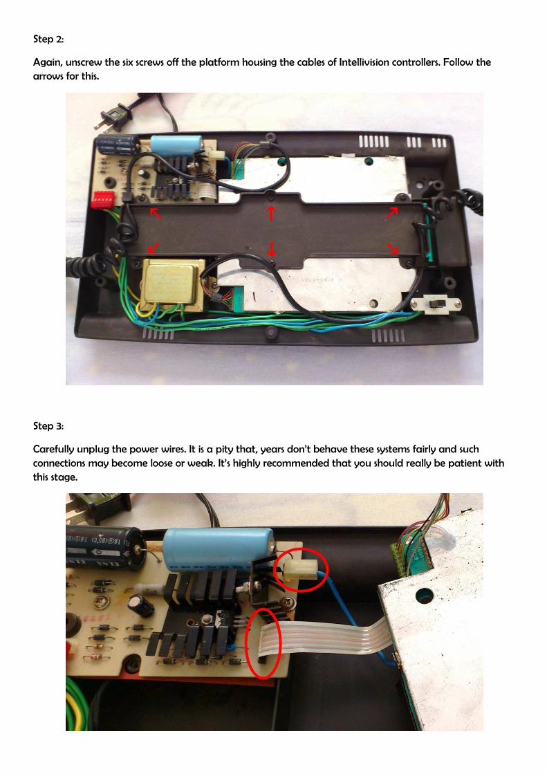
Step 2:
Again, unscrew the six screws off the platform housing the cables of Intellivision controllers. Follow the
arrows for this.
Step 3:
Carefully unplug the power wires. It is a pity that, years don’t behave these systems fairly and such
connections may become loose or weak. It’s highly recommended that you should really be patient with
this stage.
Step 4:
Now, remove the controllers from the motherboard by simply pulling the plugs away gently and
patiently. Using some piece of solder braid, de-solder the RF shielding plates off the motherboard of the
system. For Intellivision II and III, you can skip this job as they don’t have a shielding around.
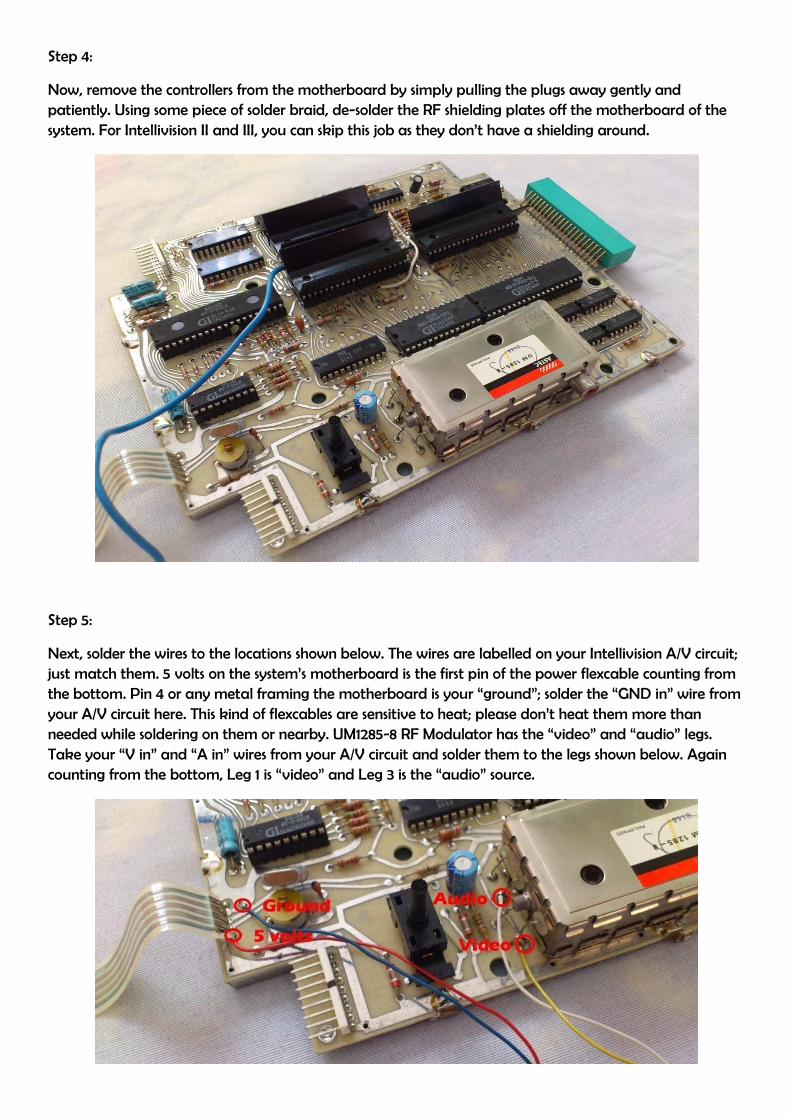
Step 5:
Next, solder the wires to the locations shown below. The wires are labelled on your Intellivision A/V circuit;
just match them. 5 volts on the system’s motherboard is the first pin of the power flexcable counting from
the bottom. Pin 4 or any metal framing the motherboard is your “ground”; solder the “GND in” wire from
your A/V circuit here. This kind of flexcables are sensitive to heat; please don’t heat them more than
needed while soldering on them or nearby. UM1285-8 RF Modulator has the “video” and “audio” legs.
Take your “V in” and “A in” wires from your A/V circuit and solder them to the legs shown below. Again
counting from the bottom, Leg 1 is “video” and Leg 3 is the “audio” source.

Here is the diagram for Intellivision II. You can solder your “GND in” wire to any open point at the
boundary of the motherboard; and you can pull your 5 volts from the light green trace shown below.
Note that IC names can sometimes change as AY
into 2114s.
Step 6:
Use your needle-nose pliers and bend the piece of metal at the black shielding as shown below. This will
be our gate for the wires going to the A/V circuit.
Here is the diagram for Intellivision II. You can solder your “GND in” wire to any open point at the
boundary of the motherboard; and you can pull your 5 volts from the light green trace shown below.
Note that IC names can sometimes change as AY-3-8916 into AY-3-8915 or AY-3
nose pliers and bend the piece of metal at the black shielding as shown below. This will
to the A/V circuit.
Here is the diagram for Intellivision II. You can solder your “GND in” wire to any open point at the
boundary of the motherboard; and you can pull your 5 volts from the light green trace shown below.
3-8914 and the AM9114s
nose pliers and bend the piece of metal at the black shielding as shown below. This will

Step 7:
Now, solder back both of the RF shielding plates and make sure your previously soldered inner wires are
not smashed in anyway. Your result for this stage should look something similar to the one below.
Step 8:
Now, remove the power supply module as shown. It has 2 screws only. Then, pass the remaining wires of
the A/V circuit through the canal below the orange cardboard. Also, now is the time to mount your “A/V
Out” connection jacks on your case. Carefully measure the final location and open the two 1/3” holes for
the Audio and Video jacks with two 1/8” holes at the sides for the screw set. Use your flat-head screwdriver
to turn the screw while holding the nut behind with your needle-nose pliers.

Step 9:
Solder your “GND out” wire from the A/V circuit to both of the jacks’ outer terminals. Your “V out” wire
should be soldered to the center terminal of the yellow jack and “A out” wire to the center terminal of
the white jack. Again, refer to the picture below.
Step 10:
Plug the power wires coming from the motherboard to the power supply unit in the way you found them
at the beginning. Attach your double-sided tape on the back of the circuit and then, to the place shown.
Make sure you place the A/V circuit as next to as possible to the “screw hole” shown on the picture.
Otherwise, it may be smashed by the piece of plastic coming over it when the case is closed. Don’t forget
to clean the place before doing this. You can, optionally, use hot glue here to add strength. Do not let the
assembly get over-thick, though.

Finalizing. . .
Now, you’re set. It’s always a good idea to check the functionality before making the thing into one piece.
Connect your Intellivision to your Tv via A/V cables and see the improvement over old snowy, wavy, and
noisy RF connection. If your mod doesn’t work, go back and double-check what you did so far. Also,
cleaning the cartridge port and the edges of your game cartridges may help. Sometimes, cartridge ports
may get filled with dust and also, game cartridge edges may catch grease or dirt. If your mod works, you
should have a nice and clear picture with noise-free sound. Now, you can reassemble your Intellivision.
Have Good Gaming Sessions!
Please do not hesitate to contact if you have anything to share or a question to ask via