inter data center workload mobility with vmware ... · ... inter data center workload mobility with...
TRANSCRIPT
IMPLEMENTATION GUIDE
Copyright © 2013, Juniper Networks, Inc. 1
INter Data CeNter WorkloaD MobIlIty WIth VMWare
although Juniper Networks has attempted to provide accurate information in this guide, Juniper Networks does not warrant or guarantee the accuracy of the information provided herein. third party product descriptions and related technical details provided in this document are for information purposes only and such products are not supported by Juniper Networks. all information provided in this guide is provided “as is”, with all faults, and without warranty of any kind, either expressed or implied or statutory. Juniper Networks and its suppliers hereby disclaim all warranties related to this guide and the information contained herein, whether expressed or implied of statutory including, without limitation, those of merchantability, fitness for a particular purpose and noninfringement, or arising from a course of dealing, usage, or trade practice.
2 Copyright © 2013, Juniper Networks, Inc.
IMPLEMENTATION GUIDE - Inter Data Center Workload Mobility with VMware
Table of ContentsIntroduction . . . . . . . . . . . . . . . . . . . . . . . . . . . . . . . . . . . . . . . . . . . . . . . . . . . . . . . . . . . . . . . . . . . . . . . . . . . . . . . . . . . . . . . . . . . . . . . . . . . . .3
Scope . . . . . . . . . . . . . . . . . . . . . . . . . . . . . . . . . . . . . . . . . . . . . . . . . . . . . . . . . . . . . . . . . . . . . . . . . . . . . . . . . . . . . . . . . . . . . . . . . . . . . . . . . . .3
Design Considerations . . . . . . . . . . . . . . . . . . . . . . . . . . . . . . . . . . . . . . . . . . . . . . . . . . . . . . . . . . . . . . . . . . . . . . . . . . . . . . . . . . . . . . . . . . . 4
Distance and latency . . . . . . . . . . . . . . . . . . . . . . . . . . . . . . . . . . . . . . . . . . . . . . . . . . . . . . . . . . . . . . . . . . . . . . . . . . . . . . . . . . . . . . . . . 4
l2 Domain Considerations . . . . . . . . . . . . . . . . . . . . . . . . . . . . . . . . . . . . . . . . . . . . . . . . . . . . . . . . . . . . . . . . . . . . . . . . . . . . . . . . . . . . . 4
Congestion Point . . . . . . . . . . . . . . . . . . . . . . . . . . . . . . . . . . . . . . . . . . . . . . . . . . . . . . . . . . . . . . . . . . . . . . . . . . . . . . . . . . . . . . . . . . . . . . 4
alternative approaches . . . . . . . . . . . . . . . . . . . . . . . . . . . . . . . . . . . . . . . . . . . . . . . . . . . . . . . . . . . . . . . . . . . . . . . . . . . . . . . . . . . . . . . . 4
VMware vMotion . . . . . . . . . . . . . . . . . . . . . . . . . . . . . . . . . . . . . . . . . . . . . . . . . . . . . . . . . . . . . . . . . . . . . . . . . . . . . . . . . . . . . . . . . . . . . . . . 5
Network Implications . . . . . . . . . . . . . . . . . . . . . . . . . . . . . . . . . . . . . . . . . . . . . . . . . . . . . . . . . . . . . . . . . . . . . . . . . . . . . . . . . . . . . . . . . . 6
Maintaining State for traffic Flows . . . . . . . . . . . . . . . . . . . . . . . . . . . . . . . . . . . . . . . . . . . . . . . . . . . . . . . . . . . . . . . . . . . . . . . . . . . . . .7
Implementation overview . . . . . . . . . . . . . . . . . . . . . . . . . . . . . . . . . . . . . . . . . . . . . . . . . . . . . . . . . . . . . . . . . . . . . . . . . . . . . . . . . . . . . . . . 8
Metro vMotion . . . . . . . . . . . . . . . . . . . . . . . . . . . . . . . . . . . . . . . . . . . . . . . . . . . . . . . . . . . . . . . . . . . . . . . . . . . . . . . . . . . . . . . . . . . . . . . . 8
optimizing traffic Flows after Migration . . . . . . . . . . . . . . . . . . . . . . . . . . . . . . . . . . . . . . . . . . . . . . . . . . . . . . . . . . . . . . . . . . . . . . . . 11
Implementation . . . . . . . . . . . . . . . . . . . . . . . . . . . . . . . . . . . . . . . . . . . . . . . . . . . . . . . . . . . . . . . . . . . . . . . . . . . . . . . . . . . . . . . . . . . . . . . . . 12
QFX3600-QFX003 in DC1 Configuration . . . . . . . . . . . . . . . . . . . . . . . . . . . . . . . . . . . . . . . . . . . . . . . . . . . . . . . . . . . . . . . . . . . . . . . . 13
eX4200-VC in DC2 Configuration . . . . . . . . . . . . . . . . . . . . . . . . . . . . . . . . . . . . . . . . . . . . . . . . . . . . . . . . . . . . . . . . . . . . . . . . . . . . . . 14
MX960-MX13 in DC1 Configuration . . . . . . . . . . . . . . . . . . . . . . . . . . . . . . . . . . . . . . . . . . . . . . . . . . . . . . . . . . . . . . . . . . . . . . . . . . . . . 15
MX960-MX14 in DC1 Configuration . . . . . . . . . . . . . . . . . . . . . . . . . . . . . . . . . . . . . . . . . . . . . . . . . . . . . . . . . . . . . . . . . . . . . . . . . . . . .19
Validation . . . . . . . . . . . . . . . . . . . . . . . . . . . . . . . . . . . . . . . . . . . . . . . . . . . . . . . . . . . . . . . . . . . . . . . . . . . . . . . . . . . . . . . . . . . . . . . . . . . . . . 30
Validation Using the vCenter Client application . . . . . . . . . . . . . . . . . . . . . . . . . . . . . . . . . . . . . . . . . . . . . . . . . . . . . . . . . . . . . . . . 34
Summary . . . . . . . . . . . . . . . . . . . . . . . . . . . . . . . . . . . . . . . . . . . . . . . . . . . . . . . . . . . . . . . . . . . . . . . . . . . . . . . . . . . . . . . . . . . . . . . . . . . . . . 35
about Juniper Networks . . . . . . . . . . . . . . . . . . . . . . . . . . . . . . . . . . . . . . . . . . . . . . . . . . . . . . . . . . . . . . . . . . . . . . . . . . . . . . . . . . . . . . . . . 35
List of FiguresFigure 1: Minimum required networks . . . . . . . . . . . . . . . . . . . . . . . . . . . . . . . . . . . . . . . . . . . . . . . . . . . . . . . . . . . . . . . . . . . . . . . . . . . . . . 6
Figure 2: redundant virtual and physical network connectivity design . . . . . . . . . . . . . . . . . . . . . . . . . . . . . . . . . . . . . . . . . . . . . . . .7
Figure 3: three-tier traffic flow . . . . . . . . . . . . . . . . . . . . . . . . . . . . . . . . . . . . . . . . . . . . . . . . . . . . . . . . . . . . . . . . . . . . . . . . . . . . . . . . . . . 8
Figure 4: three-tier traffic flow within the same physical host . . . . . . . . . . . . . . . . . . . . . . . . . . . . . . . . . . . . . . . . . . . . . . . . . . . . . . 8
Figure 5: traffic flow before metro vMotion . . . . . . . . . . . . . . . . . . . . . . . . . . . . . . . . . . . . . . . . . . . . . . . . . . . . . . . . . . . . . . . . . . . . . . . . 9
Figure 6: traffic flow during metro vMotion . . . . . . . . . . . . . . . . . . . . . . . . . . . . . . . . . . . . . . . . . . . . . . . . . . . . . . . . . . . . . . . . . . . . . . . . 9
Figure 7: traffic flow after metro vMotion . . . . . . . . . . . . . . . . . . . . . . . . . . . . . . . . . . . . . . . . . . . . . . . . . . . . . . . . . . . . . . . . . . . . . . . . .10
Figure 8: Data center workload mobility, network configuration . . . . . . . . . . . . . . . . . . . . . . . . . . . . . . . . . . . . . . . . . . . . . . . . . . . . . 12
Figure 9: Ping traffic from client to server . . . . . . . . . . . . . . . . . . . . . . . . . . . . . . . . . . . . . . . . . . . . . . . . . . . . . . . . . . . . . . . . . . . . . . . . 34
Figure 10: time and success of the vMotion event . . . . . . . . . . . . . . . . . . . . . . . . . . . . . . . . . . . . . . . . . . . . . . . . . . . . . . . . . . . . . . . . 35
Copyright © 2013, Juniper Networks, Inc. 3
IMPLEMENTATION GUIDE - Inter Data Center Workload Mobility with VMware
Introduction Implementing server virtualization results in higher utilization and reduced capital expenditure on physical servers.
Server virtualization abstracts the server operating system from the server hardware, allowing physical resources to be
shared among many virtual servers or virtual machines (VMs). the basic features of cloning, suspending, and migrating
live VMs among a cluster of physical hosts enable new applications to be built on top of these features – including
applications that migrate VMs based on resource availability.
VM migration technology was originally designed to accommodate a cluster of servers located near each other.
however, advancements in networking technology now allow servers within a single cluster to be located across the
entire data center, in an adjacent building or across the city.
Scopethis document presents design considerations and configurations for server and virtualization administrators, security
and network administrators, and designers and architects who want to extend their VM resource clusters beyond a set
of racks in the data center (the original design purpose) and migrate them to additional data centers. VMware vSphere,
including its vMotion function, is a dominant player in the enterprise x86 server virtualization market. Juniper has used
this product to verify the network design. the concepts discussed here can also be applied to other server virtualization
products from IbM, Microsoft, Citrix, and others.
Use Cases
enterprises are leveraging live workload migration in several ways. Some use cases include:
• Optimizing resource utilization. the most common use case is optimizing resource utilization within a single data center.
there are several reasons for this:
- If a VM requires more compute resources than provided by the server, it can be migrated to another server in the cluster
with available resources or migrate nonprioritized VMs to make room for the resources needed.
- If fewer servers can serve the total resources required by applications in the cluster, VMs can be migrated to a smaller
group of servers. Shutting down excess servers saves power and cooling costs.
- If technical server problems occur or if the server is to be brought offline for maintenance purposes, the VMs can be
migrated to another server.
• Campus migration. VMs are migrated from one data center to another for resource consumption purposes. this scenario
is similar to the above use case but instead of the cluster residing in one data center, it is distributed over a short distance
(multiple kilometers or miles) to different buildings within the organization. typically, the campus owner owns the
backbone network and therefore has control over bandwidth and latency resources for the backbone. because only one
ingress and egress point exists in the network for external traffic, the problem of route optimization is not a limiting factor
for VM migration compared to data centers that are separated by a larger geographical distance and have their own
connections to multiple service providers and the Internet.
• Hybrid cloud. the migration of VMs between private data centers and a private or public cloud service is called the hybrid
cloud approach (or cloud bursting). Workloads in VMs are burst from the enterprise data center to the service provider’s
data center when they exceed available resources in their original data center. this alternative works well for special
projects with large, unpredictable workloads. typically, the enterprise forms a contract with the service provider to handle
this type of traffic and possibly a VPN if traffic must be isolated from the Internet.
• Disaster avoidance. administrators can nondisruptively migrate machines to another data center before a natural
disaster strikes, preventing loss of data and operation time. If a disaster is expected, such as a severe storm, an
administrator can migrate VMs to the backup data center while still operational. to do so, administrators must reserve
bandwidth on a high-bandwidth, low-latency link to handle traffic when live migration starts. It is difficult to estimate
how much bandwidth is required and how long the migration can take because users are updating VMs constantly, and
live migration must continue sending the VM state updates. It is expensive to have the bandwidth available just in case it
is needed, so an easier and less expensive alternative is to implement a backup plan of shutting down VMs, copying, and
restarting. this approach reduces the bandwidth for VMs that are not operating and the time required to transfer them.
Data from VMs can be backed up as part of a scheduled plan.
• Follow the sun. Moving users’ resources (VMs) to an advantageous location as the workday progresses can lower
resource costs. Workloads are transferred from data center to data center based on the time of day.

4 Copyright © 2013, Juniper Networks, Inc.
IMPLEMENTATION GUIDE - Inter Data Center Workload Mobility with VMware
Design ConsiderationsDistance and Latencylow latency is a requirement for clustering VMs because of the sensitivity of the heartbeat that detects a failure
in the system. In a vMotion event, latency is also important because the vMotion migration process is a chatty
communications stream that requires synchronization of memory pages between two VMs. the synchronization
ensures that the moved VM starts in exactly the same state and time as when the initial VM stopped. as distance
increases, so does latency between these two VMs, causing reduced effective bandwidth. If the VM cannot receive
replies or acknowledgements, it cannot transmit its state, and memory synchronization cannot occur. VMware imposes
a minimum of 250 Mbps on throughput for vMotion and a maximum of 5-ms latency in the standard version, with 10
ms of latency for versions using the Metro vMotion feature. VMware recommends a maximum of 5 ms of latency and a
200 km distance between users and the virtualized applications.
the two main factors that affect latency in data center networks and interconnections are propagation delay (caused
by distance) and processing delay. Serialization delay is less important because of the size and amount of bandwidth
required in these use cases. electronic manipulation of the packet causes processing delay, so any switching, routing,
firewalling, or load balancing causes delay. Most types of delays are measured in microseconds (μs, which is 1/1000th
of a millisecond). the propagation delay is a function of the speed of light, and a conservative estimate of delay over
fiber optics is approximately 5 μs per km. one way to decipher the delay budget of 5 ms is to look at the distance
latency measured purely as propagation delay. the propagation delay over fiber with a 5-ms budget is 1,000 km. For
round-trip packets, divide by two to get the 5-ms round-trip time (rtt) for 500 km.
Processing delay is unique for each network and varies by device based on software, hardware, functions, features, and
the age of the technology. you can assume the following requirements: 5 to 20 μs per switch; 20 to 100 microseconds
per router; and 20 to 300 μs per firewall. a rule of thumb states a minimum of two switches, a single router and one
firewall per data center are required. In a worst case scenario and only allowing a unidirectional path, processing delay
totals 80 μs in switch delay, 200 μs in router delay, and 600 μs in firewall delay. bidirectionally, this totals a 1760-μs
delay of the 5,000-μs delay budget, leaving approximately 3,000 μs or about 600-km worth of propagation delay, 300
km bidirectionally.
these figures do not include packet size, serialization delay, and queuing delay. It is safe to assume that a distance
below 300 km provides a safer latency target, because it allows more devices to be in the path which cause further
processing delays. In addition, several devices might be implemented in the software, which traditionally incurs higher
processing delays. another point to note is that the distance the fiber route travels is often not a direct line between
two points. obtaining the real distance that the circuit travels is important. Different storage vendors’ synchronized
storage solutions often recommend distances below 100 km.
L2 Domain ConsiderationsStretching an l2 domain—extending the geographical distance—typically by interconnecting data centers, increases
the number of devices within the domain. the domain is still susceptible to misconfigured, maliciously configured, or
faulty devices. the technology commonly used to provide large-scale l2 laN extension (VPlS) includes mechanisms
to rate-limit this type of traffic that floods across a MaN or WaN. Maliciously configured devices can be detected and
halted by intrusion prevention systems (IPS) and firewall services.
Congestion PointWhen referring to data center architecture, the bandwidth congestion point is at the MaN or WaN edge for the DCI
(Data Center Interconnect), because this is the most expensive link in the network. It is important to have class
of service (CoS) enabled here to ensure that important latency- and bandwidth-sensitive traffic is serviced in a
predictable and reliable manner. you need to ensure that vMotion traffic has a higher priority than generic traffic. If
administrators do not prioritize the traffic, additional delay might affect vMotion. this type of delay is called queuing
delay and occurs at each point in the network where congestion exists.
Alternative Approachesthe following alternative methods might meet the needs without requiring live workload migration.
Routed Live Migrationas an alternative to l2 stretch, you can use an l3 live migration, which many hypervisor vendors support, such as
Microsoft, kVM, and Citrix. this method allows administrators to change IP and MaC addresses and use Dynamic host
Configuration Protocol/Domain Name System (DhCP/DNS) updates to force quicker changes. Implementations can
also use session tunneling to keep existing sessions alive, if required.
Copyright © 2013, Juniper Networks, Inc. 5
IMPLEMENTATION GUIDE - Inter Data Center Workload Mobility with VMware
Cold MigrationMigrating VMs live and maintaining sessions creates complexity in the network, as previously discussed. If live
migration is not a requirement, cold migration is a good option. With a cold migration, VMs are shut down, moved, and
restarted. Many organizations find that this is an excellent way to share work with global teams.
VM Migration Using Load Balancingadministrators can create or clone a new VM in the second data center, and new traffic is then forwarded to the new
VM through load balancing. the original VM stops operating when all traffic has been offloaded. this is a common
and well-established method of scaling traffic that does not have location or IP restrictions. however, it does not
specifically move a live server with live sessions from one location to another.
VMware vMotionthe implementation described in this document uses VMware vMotion to provide live workload migration. live
migration is one of the key capabilities that caused users to switch to virtualization. live migration enables many
useful applications, such as Distributed resource Scheduler (DrS), Distributed Power Management (DPM), and Fault
tolerance. vMotion transfers the running contents of a VM’s memory to another host. the vMotion component of
vSphere version 5 does the following:
1. Creates a shadow VM on the destination host.
2. Places traces on all the VM’s memory.
3. Copies memory pages from the source VM host to the destination VM host.
4. Copies memory pages that have changed during the first copy.
5. Continues this process iteratively until a threshold is met where nearly all memory pages have been transferred.
6. Stops (quiesces) the source VM.
7. Copies the state of the VM’s CPU, video, network, disk, and storage.
8. Copies final memory page changes, and resumes operation on the destination host’s VM.
9. Sends reverse address resolution Protocol (arP) to the network to ensure that traffic is forwarded to its location
via the destination host VM.
two additional points worth noting are:
• vMotion is not by itself a high-availability mechanism. vSphere has a feature called high availability that can restart VMs
based on VM or host failures or through an additional product called Site recovery Manager (SrM).
• vMotion is designed to migrate a VM and all of its current execution state from one host to another. From a network
perspective, you want to maintain all active sessions between the VM and other hosts on the network, as well as inherit
the source VM’s IP and media access control (MaC) addresses on the destination hosts.
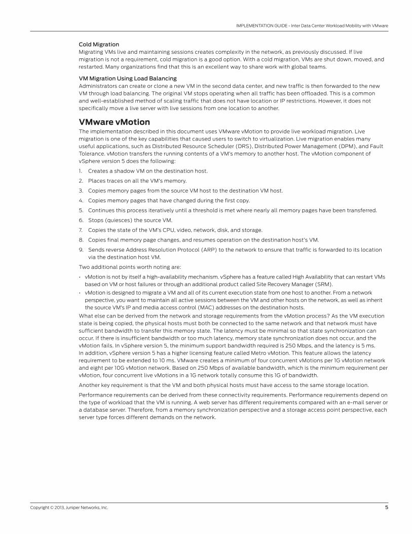
What else can be derived from the network and storage requirements from the vMotion process? as the VM execution
state is being copied, the physical hosts must both be connected to the same network and that network must have
sufficient bandwidth to transfer this memory state. the latency must be minimal so that state synchronization can
occur. If there is insufficient bandwidth or too much latency, memory state synchronization does not occur, and the
vMotion fails. In vSphere version 5, the minimum support bandwidth required is 250 Mbps, and the latency is 5 ms.
In addition, vSphere version 5 has a higher licensing feature called Metro vMotion. this feature allows the latency
requirement to be extended to 10 ms. VMware creates a minimum of four concurrent vMotions per 1G vMotion network
and eight per 10G vMotion network. based on 250 Mbps of available bandwidth, which is the minimum requirement per
vMotion, four concurrent live vMotions in a 1G network totally consume this 1G of bandwidth.
another key requirement is that the VM and both physical hosts must have access to the same storage location.
Performance requirements can be derived from these connectivity requirements. Performance requirements depend on
the type of workload that the VM is running. a web server has different requirements compared with an e-mail server or
a database server. therefore, from a memory synchronization perspective and a storage access point perspective, each
server type forces different demands on the network.
6 Copyright © 2013, Juniper Networks, Inc.
IMPLEMENTATION GUIDE - Inter Data Center Workload Mobility with VMware
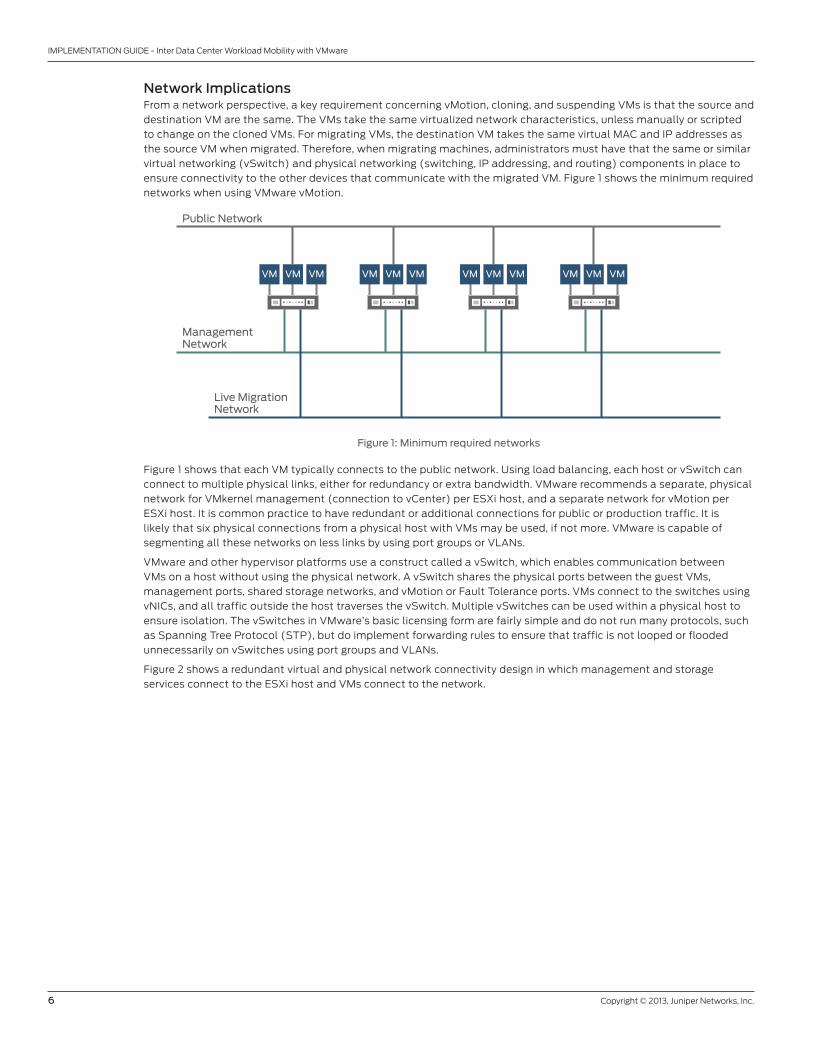
Network ImplicationsFrom a network perspective, a key requirement concerning vMotion, cloning, and suspending VMs is that the source and
destination VM are the same. the VMs take the same virtualized network characteristics, unless manually or scripted
to change on the cloned VMs. For migrating VMs, the destination VM takes the same virtual MaC and IP addresses as
the source VM when migrated. therefore, when migrating machines, administrators must have that the same or similar
virtual networking (vSwitch) and physical networking (switching, IP addressing, and routing) components in place to
ensure connectivity to the other devices that communicate with the migrated VM. Figure 1 shows the minimum required
networks when using VMware vMotion.
Figure 1: Minimum required networks
Figure 1 shows that each VM typically connects to the public network. Using load balancing, each host or vSwitch can
connect to multiple physical links, either for redundancy or extra bandwidth. VMware recommends a separate, physical
network for VMkernel management (connection to vCenter) per eSXi host, and a separate network for vMotion per
eSXi host. It is common practice to have redundant or additional connections for public or production traffic. It is
likely that six physical connections from a physical host with VMs may be used, if not more. VMware is capable of
segmenting all these networks on less links by using port groups or VlaNs.
VMware and other hypervisor platforms use a construct called a vSwitch, which enables communication between
VMs on a host without using the physical network. a vSwitch shares the physical ports between the guest VMs,
management ports, shared storage networks, and vMotion or Fault tolerance ports. VMs connect to the switches using
vNICs, and all traffic outside the host traverses the vSwitch. Multiple vSwitches can be used within a physical host to
ensure isolation. the vSwitches in VMware’s basic licensing form are fairly simple and do not run many protocols, such
as Spanning tree Protocol (StP), but do implement forwarding rules to ensure that traffic is not looped or flooded
unnecessarily on vSwitches using port groups and VlaNs.
Figure 2 shows a redundant virtual and physical network connectivity design in which management and storage
services connect to the eSXi host and VMs connect to the network.
Public Network
ManagementNetwork
Live Migration Network
VM VM VM VM VM VM VM VM VM VM VM VM

Copyright © 2013, Juniper Networks, Inc. 7
IMPLEMENTATION GUIDE - Inter Data Center Workload Mobility with VMware
Figure 2: Redundant virtual and physical network connectivity design
the vMotion process and vSwitch have the following network requirements:
• l2 connections between the hosts on the vMotion network
• Same l2 public or data network present in both data centers to ensure that network sessions are not interrupted
• Shared storage (replicated in the MaN to avoid DCI usage)
• VlaN trunking to the server if multiple VlaNs per port exist
• Same port groups and VlaNs for all vMotion-capable servers in an eSXi cluster
• When network changes are made, configuration of the server, vSwitch, switches, and routers
• less than 5–10 ms latency (less latency is better; deterministic latency is best)
• Minimum of 250 Mbps bandwidth link per vMotion (more bandwidth is better)
• Network reliability and redundancy
Maintaining State for Traffic FlowsWhen migrating VMs with vMotion, administrators must consider that the destination host VM assumes all the
characteristics of the source VM, and the IP and MaC addresses move to a new location in the network. If relocation
causes the VM to shift from one stateful service device (load balancer or firewall) to another, it is likely that the
new device will not recognize the network session state of applications running on the VM and block these network
communications, as they are designed to do. this causes the application to reset the session and, as a result, shows as
a non-seamless VM move.
to avoid this, we implement a design that forces all existing sessions through the original stateful service device,
resulting in non-optimal traffic routing and bandwidth usage for the DCI. administrators can use alternate designs
that maintain session state between the stateful service devices of the source VM’s host and destination VM’s host.
typically, clustering resolves this alternate option.
Clustering is another technology that typically works in laN environments or with devices located next to each
other. Using clustered stateful devices in a WaN environment might not be optimal or might create similar problems
compared to vMotion. In addition, clustered stateful devices have bandwidth and latency requirements, which might
not be compatible with vMotion requirements.
QFX Seriesor EX Series
QFX Seriesor EX Series
QFX Seriesor EX Series
QFX Seriesor EX Series
ESXi Host
Server VM
Service VM(Network Virtualization,
Load Balancing, NAT, Security)
Serviced VM
vMotion/FTVMK NICInterface
ESXi HostManagement
VMK NICInterface
vSwitchesor Port Groups
PhysicalPorts
IP StorageVMK NICInterface
Virtual NICs
VirtualizedNon-Virtualized
8 Copyright © 2013, Juniper Networks, Inc.
IMPLEMENTATION GUIDE - Inter Data Center Workload Mobility with VMware
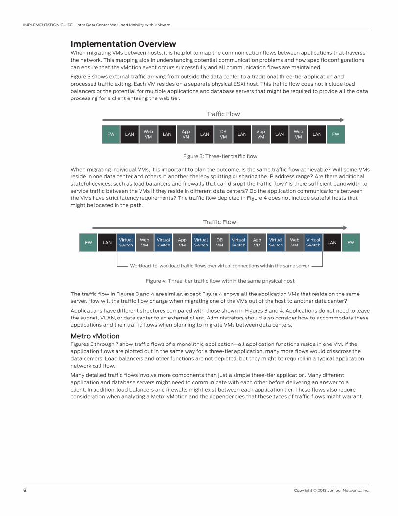
Implementation OverviewWhen migrating VMs between hosts, it is helpful to map the communication flows between applications that traverse
the network. this mapping aids in understanding potential communication problems and how specific configurations
can ensure that the vMotion event occurs successfully and all communication flows are maintained.
Figure 3 shows external traffic arriving from outside the data center to a traditional three-tier application and
processed traffic exiting. each VM resides on a separate physical eSXi host. this traffic flow does not include load
balancers or the potential for multiple applications and database servers that might be required to provide all the data
processing for a client entering the web tier.
Figure 3: Three-tier traffic flow
When migrating individual VMs, it is important to plan the outcome. Is the same traffic flow achievable? Will some VMs
reside in one data center and others in another, thereby splitting or sharing the IP address range? are there additional
stateful devices, such as load balancers and firewalls that can disrupt the traffic flow? Is there sufficient bandwidth to
service traffic between the VMs if they reside in different data centers? Do the application communications between
the VMs have strict latency requirements? the traffic flow depicted in Figure 4 does not include stateful hosts that
might be located in the path.
Figure 4: Three-tier traffic flow within the same physical host
the traffic flow in Figures 3 and 4 are similar, except Figure 4 shows all the application VMs that reside on the same
server. how will the traffic flow change when migrating one of the VMs out of the host to another data center?
applications have different structures compared with those shown in Figures 3 and 4. applications do not need to leave
the subnet, VlaN, or data center to an external client. administrators should also consider how to accommodate these
applications and their traffic flows when planning to migrate VMs between data centers.
Metro vMotionFigures 5 through 7 show traffic flows of a monolithic application—all application functions reside in one VM. If the
application flows are plotted out in the same way for a three-tier application, many more flows would crisscross the
data centers. load balancers and other functions are not depicted, but they might be required in a typical application
network call flow.
Many detailed traffic flows involve more components than just a simple three-tier application. Many different
application and database servers might need to communicate with each other before delivering an answer to a
client. In addition, load balancers and firewalls might exist between each application tier. these flows also require
consideration when analyzing a Metro vMotion and the dependencies that these types of traffic flows might warrant.
Tra�c Flow
FW FWLANLAN LAN LAN LAN LANWebVM
AppVM
DBVM
AppVM
WebVM
Tra�c Flow
LAN LANFW FWVirtualSwitch
WebVM
AppVM
DBVM
AppVM
WebVM
VirtualSwitch
VirtualSwitch
VirtualSwitch
VirtualSwitch
VirtualSwitch
Workload-to-workload tra�c flows over virtual connections within the same server
Copyright © 2013, Juniper Networks, Inc. 9
IMPLEMENTATION GUIDE - Inter Data Center Workload Mobility with VMware
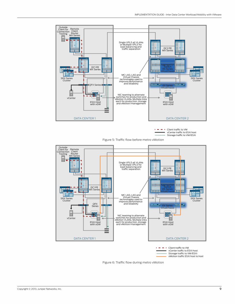
Figure 5: Traffic flow before metro vMotion
Figure 6: Traffic flow during metro vMotion
RemoteClientRouter
MX Series
OutsideClient for
ConnectionTesting
DC2 PEMX Series
SRX SeriesCluster
Client tra�c to VMvCenter tra�c to ESXi hostStorage tra�c to VM/ESXi
DC1 PEMX Series
DATA CENTER 2DATA CENTER 1
QFX Series
vCenter
SRX SeriesCluster
ESXi Hostwith vGW
ESXi Hostwith vGW
Single VPLS all VLANsor Multiple VPLS for load-balancing and
tra�c separation
MC LAG, LAG andVirtual Chassis
technologies used toimprove performance
and reliability
NIC teaming to alternateswitches for production and
vMotion VLANs. Multiple links each for production, storageand vMotion/management
AggregationSwitch
EX SeriesVirtualChassis
EX SeriesVirtualChassis
RemoteClientRouter
MX Series
OutsideClient for
ConnectionTesting
DC2 PEMX Series
SRX SeriesCluster
DC1 PEMX Series
DATA CENTER 2DATA CENTER 1
QFXSeries
vCenter
SRX SeriesCluster
ESXi Hostwith vGW
ESXi Hostwith vGW
Client trac to VMvCenter trac to ESXi hostStorage trac to VM/ESXivMotion trac ESXi host to host
Single VPLS all VLANsor Multiple VPLS for load-balancing and
trac separation
MC LAG, LAG andVirtual Chassis
technologies used toimprove performance
and reliability
NIC teaming to alternateswitches for production and
vMotion VLANs. Multiple links each for production, storageand vMotion/management
AggregationSwitch
EX SeriesVirtualChassis
EX SeriesVirtualChassis

10 Copyright © 2013, Juniper Networks, Inc.
IMPLEMENTATION GUIDE - Inter Data Center Workload Mobility with VMware
Figure 7 shows that after a vMotion migration, traffic continues to flow across the data center interconnect. In this
simple monolithic application case, traffic patterns include:
1. red-dashed flow—external client to the server now located in DC2
2. Green-dotted flow—vCenter management server in DC2 to vSphere eSXi host in DC1
3. orange-solid flow—Storage in DC2 to eSXi host in DC1
4. black (solid) flow—vCenter management server in DC1 to vSphere eSki host in DC2
these flows are problematic because the load increases through the DCI, which is the most expensive and congested
point on the network. these flows allow less bandwidth to be available for existing applications and other migration
traffic. Due to the latency incurred, the application might perform poorly because the storage and client are located
further away from the VM. Moreover, this issue is magnified because more components reside in a three-tier or larger
application.
Migrating live servers between data centers -- while maintaining existing application flows – is sometimes known as
the hairpinning or trombone effect.
Figure 7: Traffic flow after metro vMotion
AggregationSwitch
EX SeriesVirtualChassis
EX SeriesVirtualChassis
DC2 PEMX Series
SRX SeriesCluster
Client tra�c to VMvCenter tra�c to ESXi hostStorage tra�c to VM/ESXivMotion tra�c ESXi host to host
DATA CENTER 2DATA CENTER 1
vCenter
SRX SeriesCluster
ESXi Hostwith vGW
ESXi Hostwith vGW
Single VPLS all VLANsor Multiple VPLS for load-balancing and
tra�c separation
MC LAG, LAG andVirtual Chassis
technologies used toimprove performance
and reliability
NIC teaming to alternateswitches for production and
vMotion VLANs. Multiple links each for production, storageand vMotion/management
RemoteClientRouter
MX Series
OutsideClient for
ConnectionTesting
DC1 PEMX Series
QFXSeries
Copyright © 2013, Juniper Networks, Inc. 11
IMPLEMENTATION GUIDE - Inter Data Center Workload Mobility with VMware
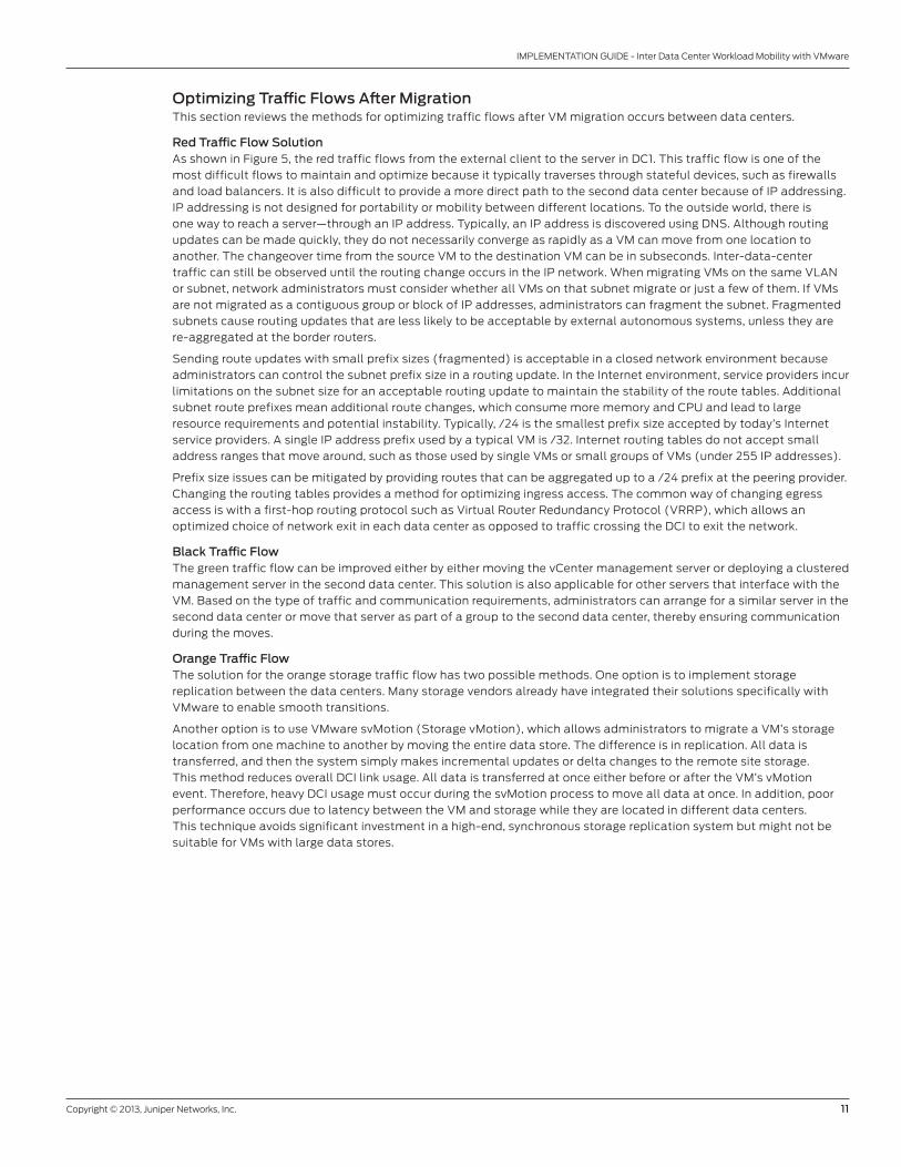
Optimizing Traffic Flows After Migrationthis section reviews the methods for optimizing traffic flows after VM migration occurs between data centers.
Red Traffic Flow Solutionas shown in Figure 5, the red traffic flows from the external client to the server in DC1. this traffic flow is one of the
most difficult flows to maintain and optimize because it typically traverses through stateful devices, such as firewalls
and load balancers. It is also difficult to provide a more direct path to the second data center because of IP addressing.
IP addressing is not designed for portability or mobility between different locations. to the outside world, there is
one way to reach a server—through an IP address. typically, an IP address is discovered using DNS. although routing
updates can be made quickly, they do not necessarily converge as rapidly as a VM can move from one location to
another. the changeover time from the source VM to the destination VM can be in subseconds. Inter-data-center
traffic can still be observed until the routing change occurs in the IP network. When migrating VMs on the same VlaN
or subnet, network administrators must consider whether all VMs on that subnet migrate or just a few of them. If VMs
are not migrated as a contiguous group or block of IP addresses, administrators can fragment the subnet. Fragmented
subnets cause routing updates that are less likely to be acceptable by external autonomous systems, unless they are
re-aggregated at the border routers.
Sending route updates with small prefix sizes (fragmented) is acceptable in a closed network environment because
administrators can control the subnet prefix size in a routing update. In the Internet environment, service providers incur
limitations on the subnet size for an acceptable routing update to maintain the stability of the route tables. additional
subnet route prefixes mean additional route changes, which consume more memory and CPU and lead to large
resource requirements and potential instability. typically, /24 is the smallest prefix size accepted by today’s Internet
service providers. a single IP address prefix used by a typical VM is /32. Internet routing tables do not accept small
address ranges that move around, such as those used by single VMs or small groups of VMs (under 255 IP addresses).
Prefix size issues can be mitigated by providing routes that can be aggregated up to a /24 prefix at the peering provider.
Changing the routing tables provides a method for optimizing ingress access. the common way of changing egress
access is with a first-hop routing protocol such as Virtual router redundancy Protocol (VrrP), which allows an
optimized choice of network exit in each data center as opposed to traffic crossing the DCI to exit the network.
Black Traffic Flow the green traffic flow can be improved either by either moving the vCenter management server or deploying a clustered
management server in the second data center. this solution is also applicable for other servers that interface with the
VM. based on the type of traffic and communication requirements, administrators can arrange for a similar server in the
second data center or move that server as part of a group to the second data center, thereby ensuring communication
during the moves.
Orange Traffic Flow the solution for the orange storage traffic flow has two possible methods. one option is to implement storage
replication between the data centers. Many storage vendors already have integrated their solutions specifically with
VMware to enable smooth transitions.
another option is to use VMware svMotion (Storage vMotion), which allows administrators to migrate a VM’s storage
location from one machine to another by moving the entire data store. the difference is in replication. all data is
transferred, and then the system simply makes incremental updates or delta changes to the remote site storage.
this method reduces overall DCI link usage. all data is transferred at once either before or after the VM’s vMotion
event. therefore, heavy DCI usage must occur during the svMotion process to move all data at once. In addition, poor
performance occurs due to latency between the VM and storage while they are located in different data centers.
this technique avoids significant investment in a high-end, synchronous storage replication system but might not be
suitable for VMs with large data stores.
12 Copyright © 2013, Juniper Networks, Inc.
IMPLEMENTATION GUIDE - Inter Data Center Workload Mobility with VMware
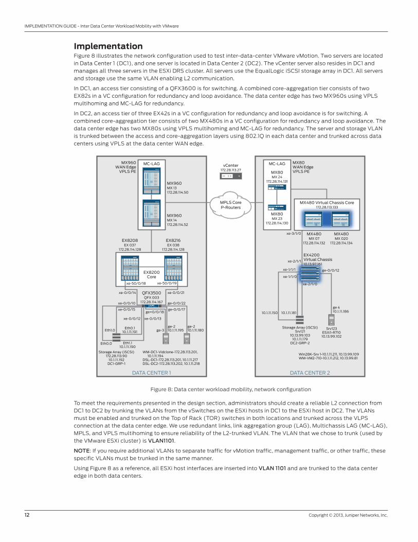
ImplementationFigure 8 illustrates the network configuration used to test inter-data-center VMware vMotion. two servers are located
in Data Center 1 (DC1), and one server is located in Data Center 2 (DC2). the vCenter server also resides in DC1 and
manages all three servers in the eSXi DrS cluster. all servers use the equallogic iSCSI storage array in DC1. all servers
and storage use the same VlaN enabling l2 communication.
In DC1, an access tier consisting of a QFX3600 is for switching. a combined core-aggregation tier consists of two
eX82s in a VC configuration for redundancy and loop avoidance. the data center edge has two MX960s using VPlS
multihoming and MC-laG for redundancy.
In DC2, an access tier of three eX42s in a VC configuration for redundancy and loop avoidance is for switching. a
combined core-aggregation tier consists of two MX480s in a VC configuration for redundancy and loop avoidance. the
data center edge has two MX80s using VPlS multihoming and MC-laG for redundancy. the server and storage VlaN
is trunked between the access and core-aggregation layers using 802.1Q in each data center and trunked across data
centers using VPlS at the data center WaN edge.
Figure 8: Data center workload mobility, network configuration
to meet the requirements presented in the design section, administrators should create a reliable l2 connection from
DC1 to DC2 by trunking the VlaNs from the vSwitches on the eSXi hosts in DC1 to the eSXi host in DC2. the VlaNs
must be enabled and trunked on the top of rack (tor) switches in both locations and trunked across the VlPS
connection at the data center edge. We use redundant links, link aggregation group (laG), Multichassis laG (MC-laG),
MPlS, and VPlS multihoming to ensure reliability of the l2-trunked VlaN. the VlaN that we chose to trunk (used by
the VMware eSXi cluster) is VLAN1101.
NOTE: If you require additional VlaNs to separate traffic for vMotion traffic, management traffic, or other traffic, these
specific VlaNs must be trunked in the same manner.
Using Figure 8 as a reference, all eSXi host interfaces are inserted into VLAN 1101 and are trunked to the data center
edge in both data centers.
vCenter172.28.113.27
xe-50/0/18 xe-50/0/19
ge-0/0/22
ge-210.1.11.180
ge-2ge-3 10.1.11.195
ge-0/0/17
xe-0/0/10
xe-0/0/15
xe-0/0/12 xe-0/0/13
Eth0.1Eth1.0
Eth0.0
10.1.11.191
Eth1.110.1.11.190
ge=0/0/18
DATA CENTER 1
MX960WAN Edge
VPLS PE
QFX3500QFX 003
172.28.114.167
EX8208EX 037
172.28.114.128
MX960MX 13172.28.114.50
EX8216EX 038
172.28.114.128
xe-0/0/14 xe-0/0/21
WM-DC1-Vidclone-172.28.113.201, 10.1.11.194
DSL-DC1-172.28.113.201, 10.1.11.217DSL-DC2-172.28.113.202, 10.1.11.218
Storage Array (iSCSI)172.28.113.90
10.1.11.192DC1-GRP-1
EX8200Core
MX960MX 14172.28.114.52
MC-LAG
DATA CENTER 2
MX80WAN EdgeVPLS PEMX80
MX 24172.28.114.131
MX80MX 23
172.28.114.130
MX480MX 07
172.28.114.132
EX4200Virtual Chassis10.13.97.161
MX480MX 020
172.28.114.134
ge-0/0/12
xe-2/1/0
xe-3/1/0
xe-2/1/1
xe-1/1/1
xe-1/1/0
10.1.11.18110.1.11.150
Win28K-Srv 1-10.1.11.211, 10.13.99.109WM-VM2-710-10.1.11.212, 10.13.99.81
10.1.11.186
Storage Array (iSCSI)Srv121
10.13.99.10310.1.11.179
DC2-GRP-2
Srv123ESXi1-R71010.13.99.102
ge 4
MC-LAG
MX480 Virtual Chassis Core172.28.113.133
MPLS CoreP-Routers
Copyright © 2013, Juniper Networks, Inc. 13
IMPLEMENTATION GUIDE - Inter Data Center Workload Mobility with VMware
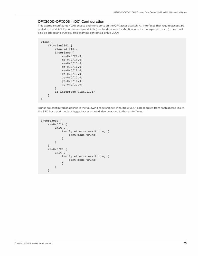
QFX3600-QFX003 in DC1 Configurationthis example configures VlaN access and trunk ports on the QFX access switch. all interfaces that require access are
added to the VlaN. If you use multiple VlaNs (one for data, one for vMotion, one for management, etc,…), they must
also be added and trunked. this example contains a single VlaN.
vlans { VR1-vlan1101 { vlan-id 1101; interface { xe-0/0/21.0; xe-0/0/14.0; xe-0/0/15.0; xe-0/0/10.0; xe-0/0/12.0; xe-0/0/13.0; ge-0/0/17.0; ge-0/0/18.0; ge-0/0/22.0; } l3-interface vlan.1101; }}
trunks are configured on uplinks in the following code snippet. If multiple VlaNs are required from each access link to
the eSXi host, port mode or tagged access should also be added to those interfaces.
interfaces { xe-0/0/14 { unit 0 { family ethernet-switching { port-mode trunk; } } } xe-0/0/21 { unit 0 { family ethernet-switching { port-mode trunk; } } }
14 Copyright © 2013, Juniper Networks, Inc.
IMPLEMENTATION GUIDE - Inter Data Center Workload Mobility with VMware
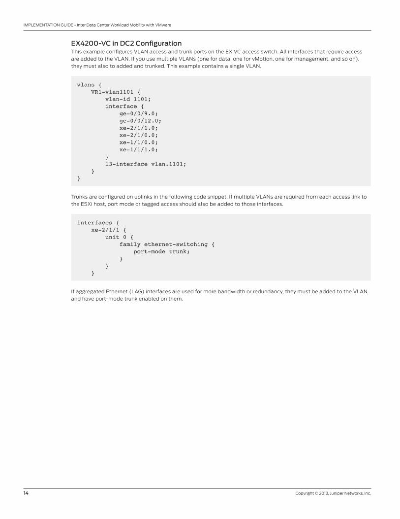
EX4200-VC in DC2 Configurationthis example configures VlaN access and trunk ports on the eX VC access switch. all interfaces that require access
are added to the VlaN. If you use multiple VlaNs (one for data, one for vMotion, one for management, and so on),
they must also to added and trunked. this example contains a single VlaN.
vlans { VR1-vlan1101 { vlan-id 1101; interface { ge-0/0/9.0; ge-0/0/12.0; xe-2/1/1.0; xe-2/1/0.0; xe-1/1/0.0; xe-1/1/1.0; } l3-interface vlan.1101; }}
trunks are configured on uplinks in the following code snippet. If multiple VlaNs are required from each access link to
the eSXi host, port mode or tagged access should also be added to those interfaces.
interfaces { xe-2/1/1 { unit 0 { family ethernet-switching { port-mode trunk; } } }
If aggregated ethernet (laG) interfaces are used for more bandwidth or redundancy, they must be added to the VlaN
and have port-mode trunk enabled on them.
Copyright © 2013, Juniper Networks, Inc. 15
IMPLEMENTATION GUIDE - Inter Data Center Workload Mobility with VMware
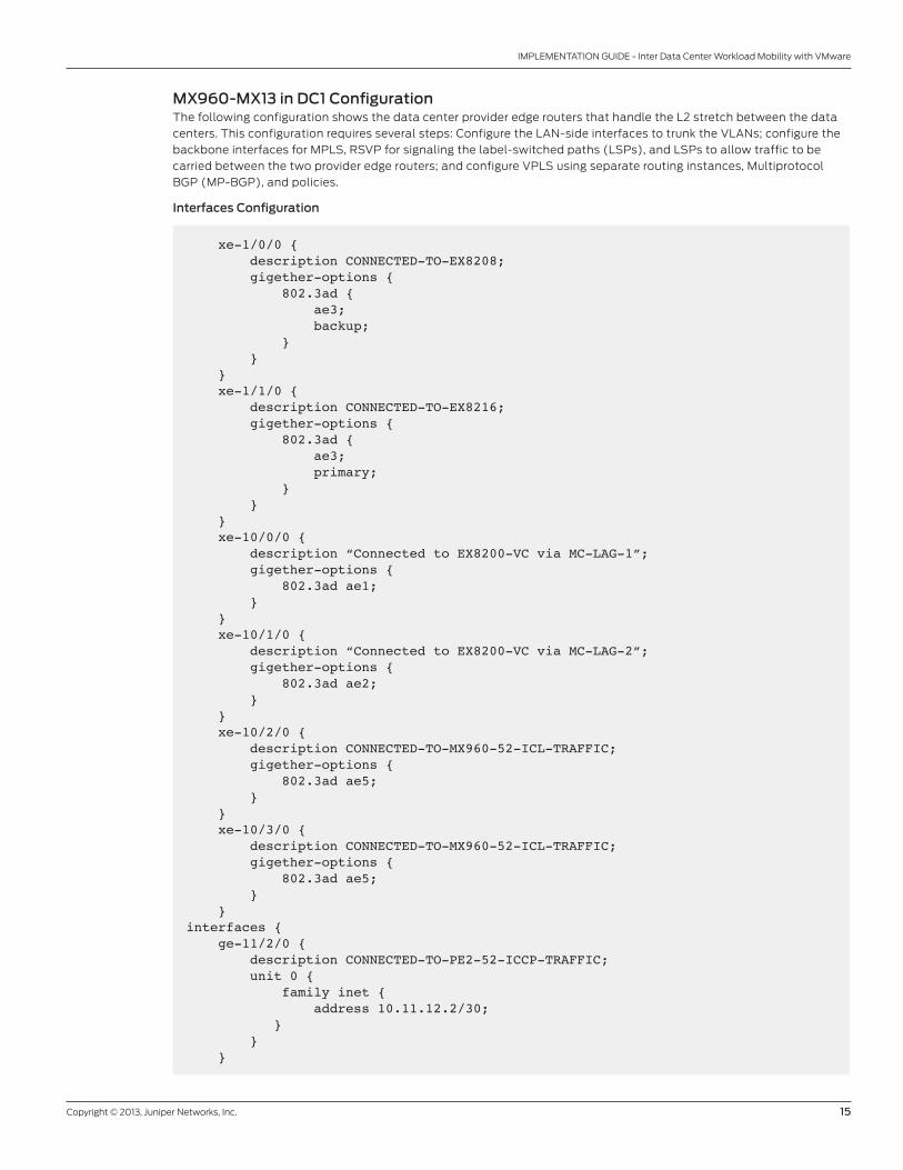
MX960-MX13 in DC1 Configurationthe following configuration shows the data center provider edge routers that handle the l2 stretch between the data
centers. this configuration requires several steps: Configure the laN-side interfaces to trunk the VlaNs; configure the
backbone interfaces for MPlS, rSVP for signaling the label-switched paths (lSPs), and lSPs to allow traffic to be
carried between the two provider edge routers; and configure VPlS using separate routing instances, Multiprotocol
bGP (MP-bGP), and policies.
Interfaces Configuration
xe-1/0/0 { description CONNECTED-TO-EX8208; gigether-options { 802.3ad { ae3; backup; } } } xe-1/1/0 { description CONNECTED-TO-EX8216; gigether-options { 802.3ad { ae3; primary; } } } xe-10/0/0 { description “Connected to EX8200-VC via MC-LAG-1”; gigether-options { 802.3ad ae1; } } xe-10/1/0 { description “Connected to EX8200-VC via MC-LAG-2”; gigether-options { 802.3ad ae2; } } xe-10/2/0 { description CONNECTED-TO-MX960-52-ICL-TRAFFIC; gigether-options { 802.3ad ae5; } } xe-10/3/0 { description CONNECTED-TO-MX960-52-ICL-TRAFFIC; gigether-options { 802.3ad ae5; } }interfaces { ge-11/2/0 { description CONNECTED-TO-PE2-52-ICCP-TRAFFIC; unit 0 { family inet { address 10.11.12.2/30; } } }

16 Copyright © 2013, Juniper Networks, Inc.
IMPLEMENTATION GUIDE - Inter Data Center Workload Mobility with VMware
MC-LAG Configuration for LAN
protocols { iccp { local-ip-addr 10.11.12.2; peer 10.11.12.1 { redundancy-group-id-list 1; liveness-detection { minimum-interval 100; multiplier 3; detection-time { threshold 500; } } } } lacp { ppm centralized; }}
interfaces { ae1 { description “Connecting to EX8200 MC-LAG-1”; flexible-vlan-tagging; encapsulation vlan-vpls; aggregated-ether-options { lacp { active; periodic fast; system-id 00:00:00:00:00:50; admin-key 123; } mc-ae { mc-ae-id 101; redundancy-group 1; chassis-id 0; mode active-standby; status-control active; } } unit 1101 { encapsulation vlan-vpls; vlan-id 1101; family vpls; } unit 1102 { encapsulation vlan-vpls; vlan-id 1102; family vpls; } unit 1103 { encapsulation vlan-vpls; vlan-id 1103; family vpls; } unit 1201 {
Copyright © 2013, Juniper Networks, Inc. 17
IMPLEMENTATION GUIDE - Inter Data Center Workload Mobility with VMware
encapsulation vlan-vpls; vlan-id 1201; family vpls; } unit 1202 { encapsulation vlan-vpls; vlan-id 1202; family vpls; } unit 1203 { encapsulation vlan-vpls; vlan-id 1203; family vpls; } }
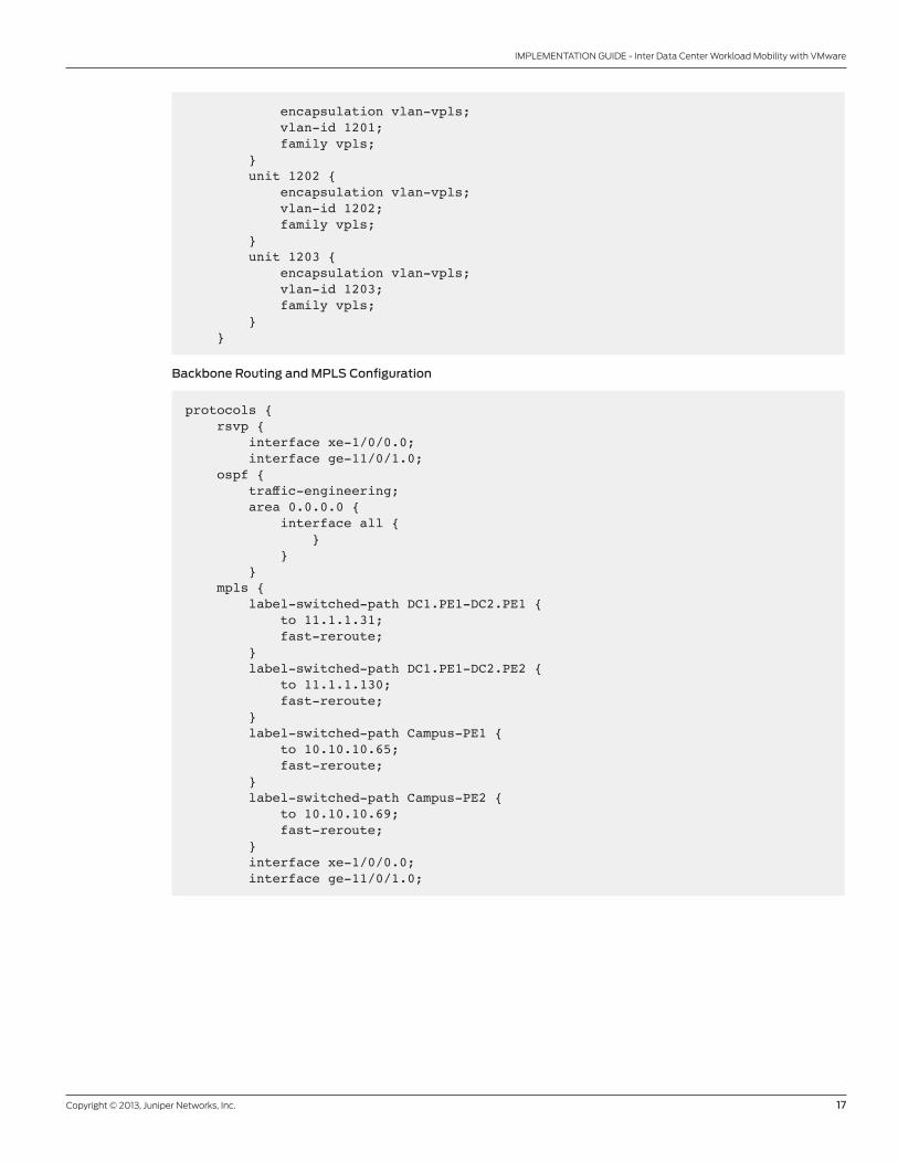
Backbone Routing and MPLS Configuration
protocols { rsvp { interface xe-1/0/0.0; interface ge-11/0/1.0; ospf { traffic-engineering; area 0.0.0.0 { interface all { } } } mpls { label-switched-path DC1.PE1-DC2.PE1 { to 11.1.1.31; fast-reroute; } label-switched-path DC1.PE1-DC2.PE2 { to 11.1.1.130; fast-reroute; } label-switched-path Campus-PE1 { to 10.10.10.65; fast-reroute; } label-switched-path Campus-PE2 { to 10.10.10.69; fast-reroute; } interface xe-1/0/0.0; interface ge-11/0/1.0;
18 Copyright © 2013, Juniper Networks, Inc.
IMPLEMENTATION GUIDE - Inter Data Center Workload Mobility with VMware
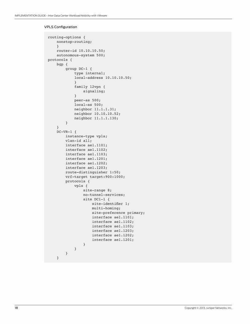
VPLS Configuration
routing-options { nonstop-routing; } router-id 10.10.10.50; autonomous-system 500;protocols { bgp { group DC-1 { type internal; local-address 10.10.10.50; } family l2vpn { signaling; } peer-as 500; local-as 500; neighbor 11.1.1.31; neighbor 10.10.10.52; neighbor 11.1.1.130; } } DC-VR-1 { instance-type vpls; vlan-id all; interface ae1.1101; interface ae1.1102; interface ae1.1103; interface ae1.1201; interface ae1.1202; interface ae1.1203; route-distinguisher 1:50; vrf-target target:900:1000; protocols { vpls { site-range 8; no-tunnel-services; site DC1-1 { site-identifier 1; multi-homing; site-preference primary; interface ae1.1101; interface ae1.1102; interface ae1.1103; interface ae1.1203; interface ae1.1202; interface ae1.1201; } } } }
Copyright © 2013, Juniper Networks, Inc. 19
IMPLEMENTATION GUIDE - Inter Data Center Workload Mobility with VMware
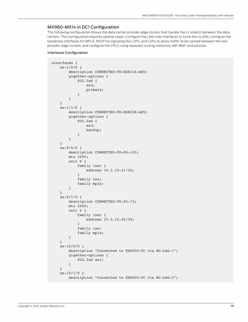
MX960-MX14 in DC1 Configurationthe following configuration shows the data center provider edge routers that handle the l2 stretch between the data
centers. this configuration requires several steps: Configure the laN-side interfaces to trunk the VlaNs; configure the
backbone interfaces for MPlS, rSVP for signaling the lSPs, and lSPs to allow traffic to be carried between the two
provider edge routers; and configure the VPlS using separate routing instances, MP-bGP, and policies.
Interfaces Configuration
interfaces { xe-1/0/0 { description CONNECTED-TO-EX8216-AE5; gigether-options { 802.3ad { ae3; primary; } } } xe-1/1/0 { description CONNECTED-TO-EX8208-AE5; gigether-options { 802.3ad { ae3; backup; } } } xe-9/0/0 { description CONNECTED-TO-P4-122; mtu 2000; unit 0 { family inet { address 10.3.10.41/30; } family iso; family mpls; } } xe-9/1/0 { description CONNECTED-TO-P2-72; mtu 2000; unit 0 { family inet { address 10.3.10.45/30; } family iso; family mpls; } } xe-10/0/0 { description “Connected to EX8200-VC via MC-LAG-1”; gigether-options { 802.3ad ae1; } } xe-10/1/0 { description “Connected to EX8200-VC via MC-LAG-2”;
20 Copyright © 2013, Juniper Networks, Inc.
IMPLEMENTATION GUIDE - Inter Data Center Workload Mobility with VMware
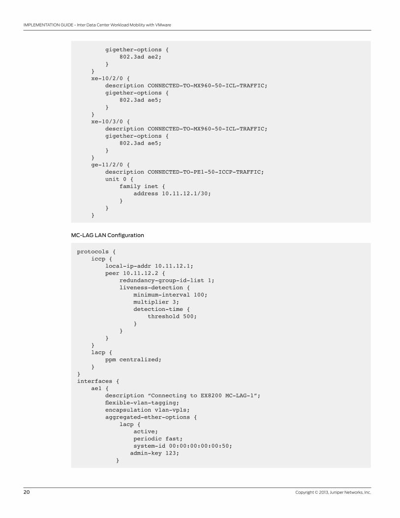
gigether-options { 802.3ad ae2; } } xe-10/2/0 { description CONNECTED-TO-MX960-50-ICL-TRAFFIC; gigether-options { 802.3ad ae5; } } xe-10/3/0 { description CONNECTED-TO-MX960-50-ICL-TRAFFIC; gigether-options { 802.3ad ae5; } } ge-11/2/0 { description CONNECTED-TO-PE1-50-ICCP-TRAFFIC; unit 0 { family inet { address 10.11.12.1/30; } } }
MC-LAG LAN Configuration
protocols { iccp { local-ip-addr 10.11.12.1; peer 10.11.12.2 { redundancy-group-id-list 1; liveness-detection { minimum-interval 100; multiplier 3; detection-time { threshold 500; } } } } lacp { ppm centralized; }}interfaces { ae1 { description “Connecting to EX8200 MC-LAG-1”; flexible-vlan-tagging; encapsulation vlan-vpls; aggregated-ether-options { lacp { active; periodic fast; system-id 00:00:00:00:00:50; admin-key 123; }
Copyright © 2013, Juniper Networks, Inc. 21
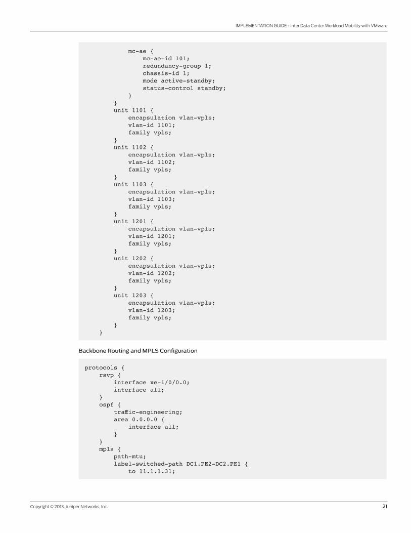
IMPLEMENTATION GUIDE - Inter Data Center Workload Mobility with VMware
mc-ae { mc-ae-id 101; redundancy-group 1; chassis-id 1; mode active-standby; status-control standby; } } unit 1101 { encapsulation vlan-vpls; vlan-id 1101; family vpls; } unit 1102 { encapsulation vlan-vpls; vlan-id 1102; family vpls; } unit 1103 { encapsulation vlan-vpls; vlan-id 1103; family vpls; } unit 1201 { encapsulation vlan-vpls; vlan-id 1201; family vpls; } unit 1202 { encapsulation vlan-vpls; vlan-id 1202; family vpls; } unit 1203 { encapsulation vlan-vpls; vlan-id 1203; family vpls; } }
Backbone Routing and MPLS Configuration
protocols { rsvp { interface xe-1/0/0.0; interface all; } ospf { traffic-engineering; area 0.0.0.0 { interface all; } } mpls { path-mtu; label-switched-path DC1.PE2-DC2.PE1 { to 11.1.1.31;
22 Copyright © 2013, Juniper Networks, Inc.
IMPLEMENTATION GUIDE - Inter Data Center Workload Mobility with VMware
} label-switched-path DC1.PE2-DC2.PE2 { to 11.1.1.130; } interface xe-1/0/0.0; interface ge-11/0/0.0; interface all;
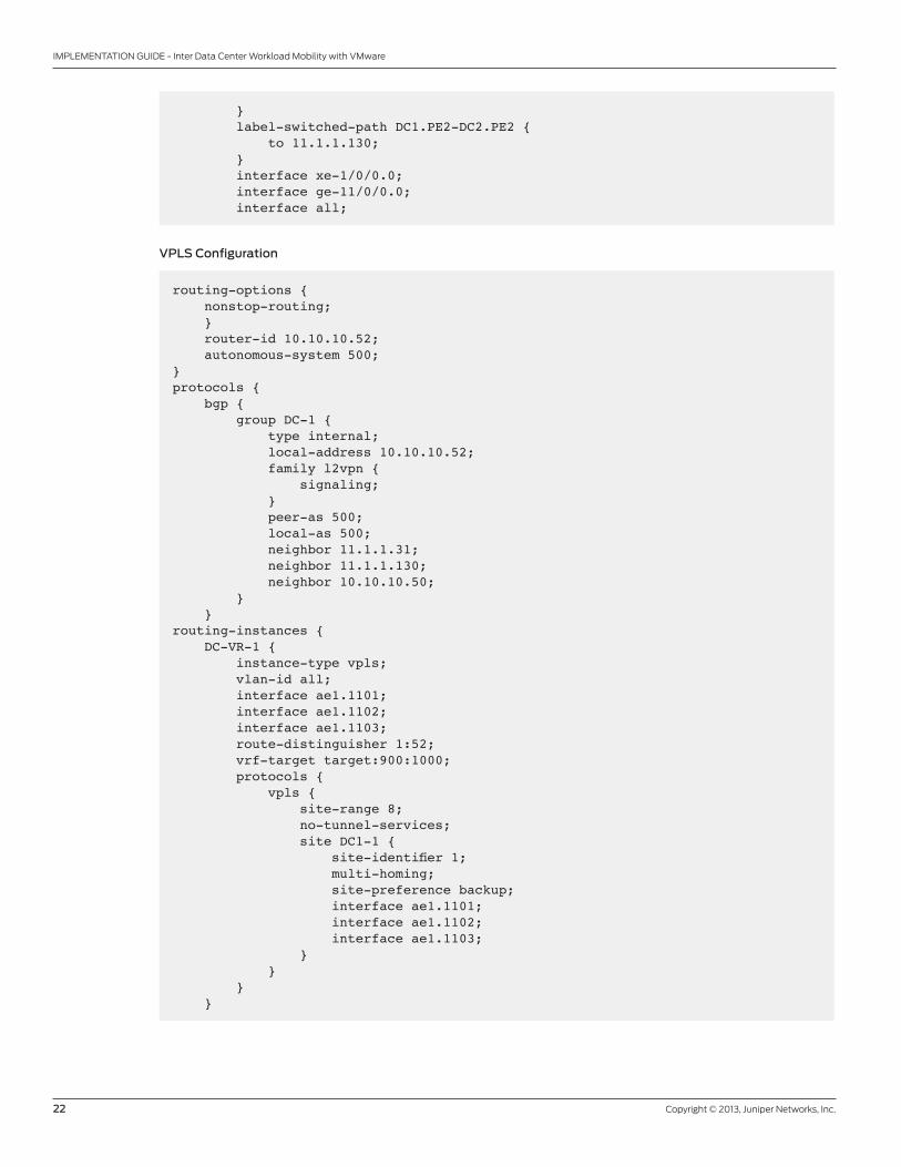
VPLS Configuration
routing-options { nonstop-routing; } router-id 10.10.10.52; autonomous-system 500;}protocols { bgp { group DC-1 { type internal; local-address 10.10.10.52; family l2vpn { signaling; } peer-as 500; local-as 500; neighbor 11.1.1.31; neighbor 11.1.1.130; neighbor 10.10.10.50; } }routing-instances { DC-VR-1 { instance-type vpls; vlan-id all; interface ae1.1101; interface ae1.1102; interface ae1.1103; route-distinguisher 1:52; vrf-target target:900:1000; protocols { vpls { site-range 8; no-tunnel-services; site DC1-1 { site-identifier 1; multi-homing; site-preference backup; interface ae1.1101; interface ae1.1102; interface ae1.1103; } } } }
Copyright © 2013, Juniper Networks, Inc. 23
IMPLEMENTATION GUIDE - Inter Data Center Workload Mobility with VMware
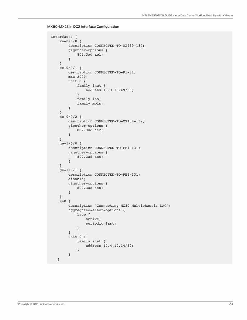
MX80-MX23 in DC2 Interface Configuration
interfaces { xe-0/0/0 { description CONNECTED-TO-MX480-134; gigether-options { 802.3ad ae1; } } xe-0/0/1 { description CONNECTED-TO-P1-71; mtu 2000; unit 0 { family inet { address 10.3.10.49/30; } family iso; family mpls; } } xe-0/0/2 { description CONNECTED-TO-MX480-132; gigether-options { 802.3ad ae2; } } ge-1/0/0 { description CONNECTED-TO-PE1-131; gigether-options { 802.3ad ae0; } } ge-1/0/1 { description CONNECTED-TO-PE1-131; disable; gigether-options { 802.3ad ae0; } } ae0 { description “Connecting MX80 Multichassis LAG”; aggregated-ether-options { lacp { active; periodic fast; } } unit 0 { family inet { address 10.4.10.14/30; } } }
24 Copyright © 2013, Juniper Networks, Inc.
IMPLEMENTATION GUIDE - Inter Data Center Workload Mobility with VMware
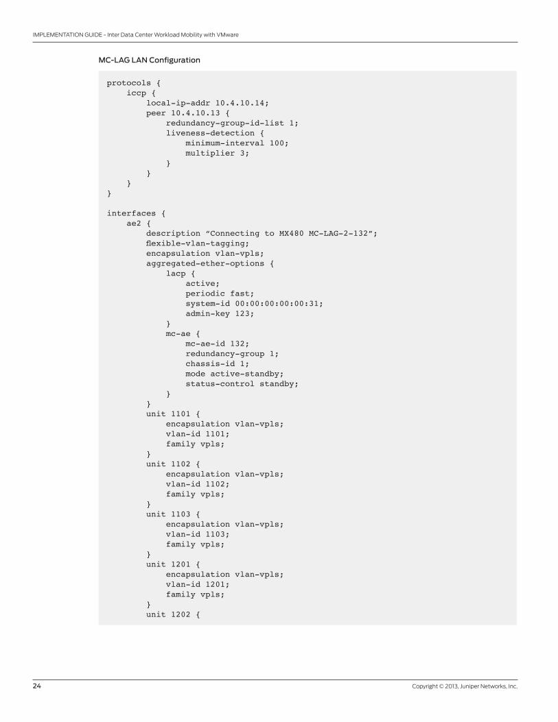
MC-LAG LAN Configuration
protocols { iccp { local-ip-addr 10.4.10.14; peer 10.4.10.13 { redundancy-group-id-list 1; liveness-detection { minimum-interval 100; multiplier 3; } } }}
interfaces { ae2 { description “Connecting to MX480 MC-LAG-2-132”; flexible-vlan-tagging; encapsulation vlan-vpls; aggregated-ether-options { lacp { active; periodic fast; system-id 00:00:00:00:00:31; admin-key 123; } mc-ae { mc-ae-id 132; redundancy-group 1; chassis-id 1; mode active-standby; status-control standby; } } unit 1101 { encapsulation vlan-vpls; vlan-id 1101; family vpls; } unit 1102 { encapsulation vlan-vpls; vlan-id 1102; family vpls; } unit 1103 { encapsulation vlan-vpls; vlan-id 1103; family vpls; } unit 1201 { encapsulation vlan-vpls; vlan-id 1201; family vpls; } unit 1202 {
Copyright © 2013, Juniper Networks, Inc. 25
IMPLEMENTATION GUIDE - Inter Data Center Workload Mobility with VMware
encapsulation vlan-vpls; vlan-id 1202; family vpls; } unit 1203 { encapsulation vlan-vpls; vlan-id 1203; family vpls; } }
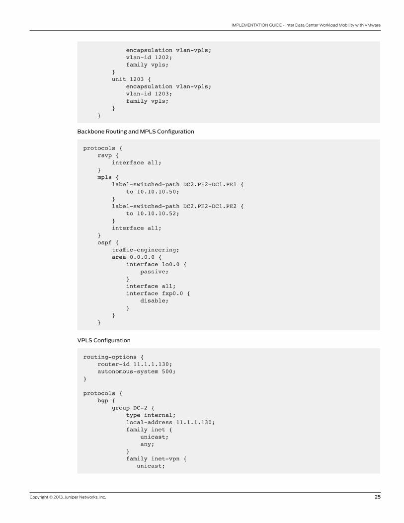
Backbone Routing and MPLS Configuration
protocols { rsvp { interface all; } mpls { label-switched-path DC2.PE2-DC1.PE1 { to 10.10.10.50; } label-switched-path DC2.PE2-DC1.PE2 { to 10.10.10.52; } interface all; } ospf { traffic-engineering; area 0.0.0.0 { interface lo0.0 { passive; } interface all; interface fxp0.0 { disable; } } }
VPLS Configuration
routing-options { router-id 11.1.1.130; autonomous-system 500;}
protocols { bgp { group DC-2 { type internal; local-address 11.1.1.130; family inet { unicast; any; } family inet-vpn { unicast;

26 Copyright © 2013, Juniper Networks, Inc.
IMPLEMENTATION GUIDE - Inter Data Center Workload Mobility with VMware
any; } family l2vpn { signaling; } peer-as 500; local-as 500; neighbor 10.10.10.50; neighbor 10.10.10.52; neighbor 11.1.1.31; } }
routing-instances { DC-VR-1 { instance-type vpls; vlan-id all; interface ae2.1101; interface ae2.1102; interface ae2.1103; interface ae2.1201; interface ae2.1202; interface ae2.1203; route-distinguisher 1:130; vrf-target target:900:1000; protocols { vpls { site-range 8; no-tunnel-services; site DC2-1 { site-identifier 3; multi-homing; site-preference backup; interface ae2.1101; interface ae2.1102; interface ae2.1103; interface ae2.1203; interface ae2.1202; interface ae2.1201; } } } }
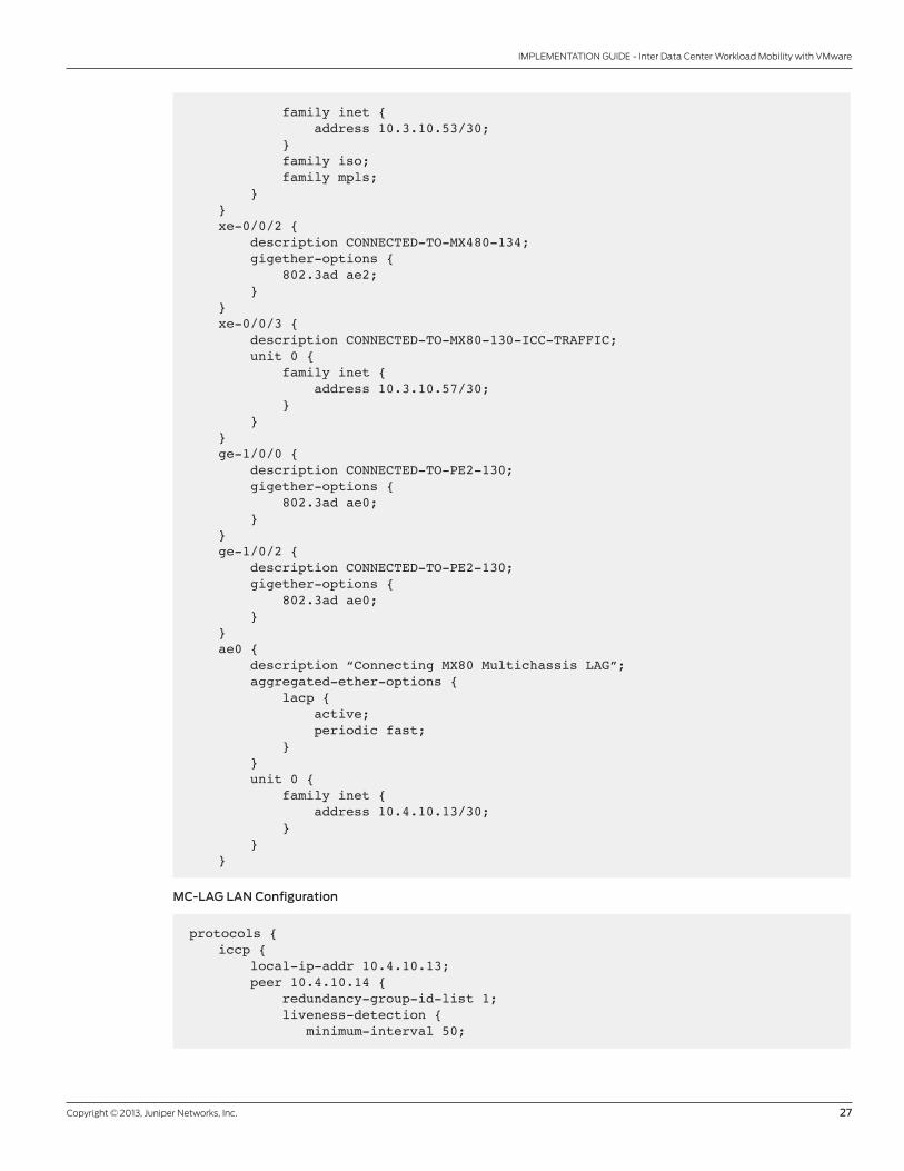
MX80-MX24 in DC2 Interface Configuration
interfaces { xe-0/0/0 { description CONNECTED-TO-MX480-132; gigether-options { 802.3ad ae1; } } xe-0/0/1 { description CONNECTED-TO-P3-92; mtu 2000; unit 0 {
Copyright © 2013, Juniper Networks, Inc. 27
IMPLEMENTATION GUIDE - Inter Data Center Workload Mobility with VMware
family inet { address 10.3.10.53/30; } family iso; family mpls; } } xe-0/0/2 { description CONNECTED-TO-MX480-134; gigether-options { 802.3ad ae2; } } xe-0/0/3 { description CONNECTED-TO-MX80-130-ICC-TRAFFIC; unit 0 { family inet { address 10.3.10.57/30; } } } ge-1/0/0 { description CONNECTED-TO-PE2-130; gigether-options { 802.3ad ae0; } } ge-1/0/2 { description CONNECTED-TO-PE2-130; gigether-options { 802.3ad ae0; } } ae0 { description “Connecting MX80 Multichassis LAG”; aggregated-ether-options { lacp { active; periodic fast; } } unit 0 { family inet { address 10.4.10.13/30; } } }
MC-LAG LAN Configuration
protocols { iccp { local-ip-addr 10.4.10.13; peer 10.4.10.14 { redundancy-group-id-list 1; liveness-detection { minimum-interval 50;
28 Copyright © 2013, Juniper Networks, Inc.
IMPLEMENTATION GUIDE - Inter Data Center Workload Mobility with VMware
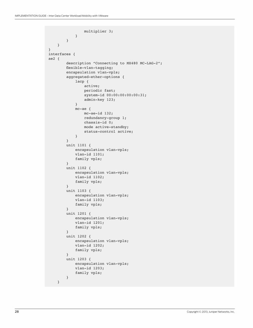
multiplier 3; } } }}interfaces {ae2 { description “Connecting to MX480 MC-LAG-2”; flexible-vlan-tagging; encapsulation vlan-vpls; aggregated-ether-options { lacp { active; periodic fast; system-id 00:00:00:00:00:31; admin-key 123; } mc-ae { mc-ae-id 132; redundancy-group 1; chassis-id 0; mode active-standby; status-control active; } } unit 1101 { encapsulation vlan-vpls; vlan-id 1101; family vpls; } unit 1102 { encapsulation vlan-vpls; vlan-id 1102; family vpls; } unit 1103 { encapsulation vlan-vpls; vlan-id 1103; family vpls; } unit 1201 { encapsulation vlan-vpls; vlan-id 1201; family vpls; } unit 1202 { encapsulation vlan-vpls; vlan-id 1202; family vpls; } unit 1203 { encapsulation vlan-vpls; vlan-id 1203; family vpls; } }
Copyright © 2013, Juniper Networks, Inc. 29
IMPLEMENTATION GUIDE - Inter Data Center Workload Mobility with VMware
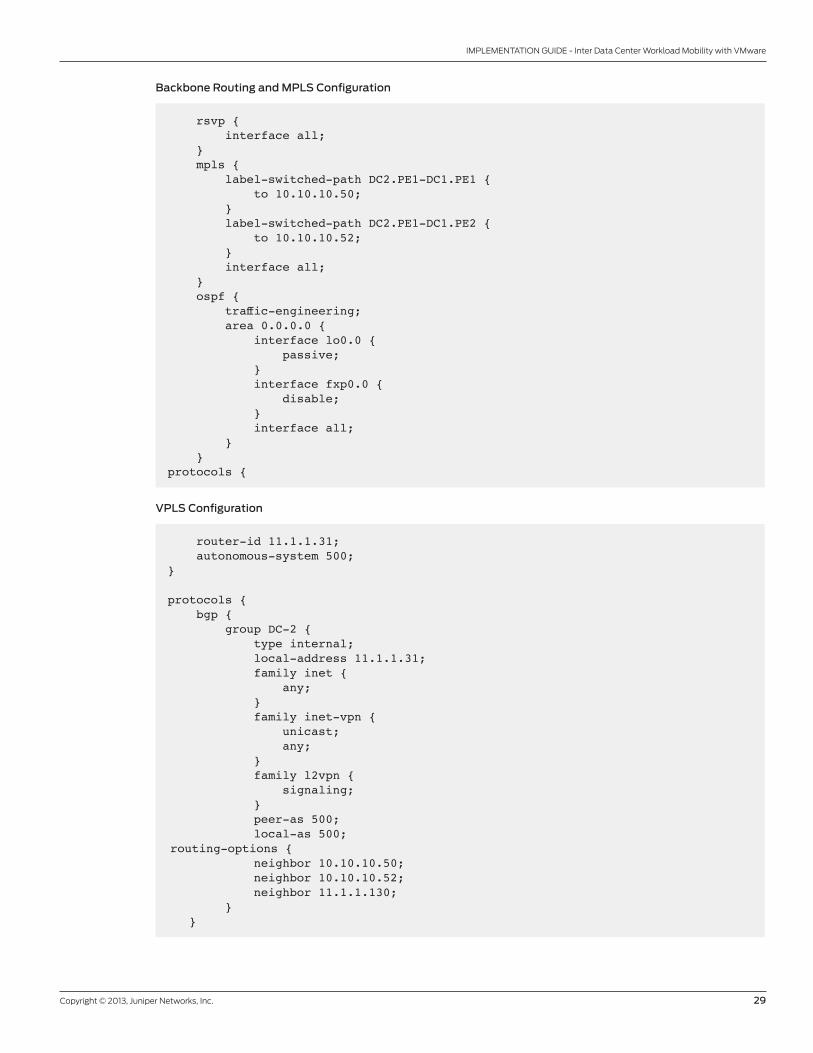
Backbone Routing and MPLS Configuration
rsvp { interface all; } mpls { label-switched-path DC2.PE1-DC1.PE1 { to 10.10.10.50; } label-switched-path DC2.PE1-DC1.PE2 { to 10.10.10.52; } interface all; } ospf { traffic-engineering; area 0.0.0.0 { interface lo0.0 { passive; } interface fxp0.0 { disable; } interface all; } }protocols {
VPLS Configuration
router-id 11.1.1.31; autonomous-system 500;}
protocols { bgp { group DC-2 { type internal; local-address 11.1.1.31; family inet { any; } family inet-vpn { unicast; any; } family l2vpn { signaling; } peer-as 500; local-as 500; routing-options { neighbor 10.10.10.50; neighbor 10.10.10.52; neighbor 11.1.1.130; } }

30 Copyright © 2013, Juniper Networks, Inc.
IMPLEMENTATION GUIDE - Inter Data Center Workload Mobility with VMware
routing-instances { DC-VR-1 { instance-type vpls; vlan-id all; interface ae2.1101; interface ae2.1102; interface ae2.1103; interface ae2.1201; interface ae2.1202; interface ae2.1203; route-distinguisher 1:131; vrf-target target:900:1000; protocols { vpls { site-range 8; no-tunnel-services; site DC2-1 { site-identifier 3; multi-homing; site-preference primary; interface ae2.1101; interface ae2.1102; interface ae2.1103; interface ae2.1201; interface ae2.1202; interface ae2.1203; } } } }
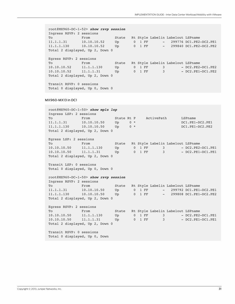
Validationthe following commands validate the MPlS configuration, mainly from the devices in DC1. For brevity, DC2 is not
shown. Validation of the successful move from the vCenter VMware management console is also shown. the following
validation shows MPlS and rSVP in DC1.
MX960-MX14 in DC1
root@MX960-DC-1-52> show mpls lsp Ingress LSP: 2 sessionsTo From State Rt P ActivePath LSPname11.1.1.31 10.10.10.52 Up 0 * DC1.PE2-DC2.PE111.1.1.130 10.10.10.52 Up 0 * DC1.PE2-DC2.PE2Total 2 displayed, Up 2, Down 0
Egress LSP: 2 sessionsTo From State Rt Style Labelin Labelout LSPname 10.10.10.52 11.1.1.130 Up 0 1 FF 3 - DC2.PE2-DC1.PE210.10.10.52 11.1.1.31 Up 0 1 FF 3 - DC2.PE1-DC1.PE2Total 2 displayed, Up 2, Down 0Transit LSP: 0 sessionsTotal 0 displayed, Up 0, Down 0
Copyright © 2013, Juniper Networks, Inc. 31
IMPLEMENTATION GUIDE - Inter Data Center Workload Mobility with VMware
root@MX960-DC-1-52> show rsvp session Ingress RSVP: 2 sessionsTo From State Rt Style Labelin Labelout LSPname 11.1.1.31 10.10.10.52 Up 0 1 FF - 299776 DC1.PE2-DC2.PE111.1.1.130 10.10.10.52 Up 0 1 FF - 299840 DC1.PE2-DC2.PE2Total 2 displayed, Up 2, Down 0
Egress RSVP: 2 sessionsTo From State Rt Style Labelin Labelout LSPname 10.10.10.52 11.1.1.130 Up 0 1 FF 3 - DC2.PE2-DC1.PE210.10.10.52 11.1.1.31 Up 0 1 FF 3 - DC2.PE1-DC1.PE2Total 2 displayed, Up 2, Down 0
Transit RSVP: 0 sessionsTotal 0 displayed, Up 0, Down 0
MX960-MX13 in DC1
root@MX960-DC-1-50> show mpls lsp Ingress LSP: 2 sessionsTo From State Rt P ActivePath LSPname11.1.1.31 10.10.10.50 Up 0 * DC1.PE1-DC2.PE111.1.1.130 10.10.10.50 Up 0 * DC1.PE1-DC2.PE2Total 2 displayed, Up 2, Down 0
Egress LSP: 2 sessionsTo From State Rt Style Labelin Labelout LSPname 10.10.10.50 11.1.1.130 Up 0 1 FF 3 - DC2.PE2-DC1.PE110.10.10.50 11.1.1.31 Up 0 1 FF 3 - DC2.PE1-DC1.PE1Total 2 displayed, Up 2, Down 0
Transit LSP: 0 sessionsTotal 0 displayed, Up 0, Down 0
root@MX960-DC-1-50> show rsvp session Ingress RSVP: 2 sessionsTo From State Rt Style Labelin Labelout LSPname 11.1.1.31 10.10.10.50 Up 0 1 FF - 299792 DC1.PE1-DC2.PE111.1.1.130 10.10.10.50 Up 0 1 FF - 299808 DC1.PE1-DC2.PE2Total 2 displayed, Up 2, Down 0
Egress RSVP: 2 sessionsTo From State Rt Style Labelin Labelout LSPname 10.10.10.50 11.1.1.130 Up 0 1 FF 3 - DC2.PE2-DC1.PE110.10.10.50 11.1.1.31 Up 0 1 FF 3 - DC2.PE1-DC1.PE1Total 2 displayed, Up 2, Down 0
Transit RSVP: 0 sessionsTotal 0 displayed, Up 0, Down
32 Copyright © 2013, Juniper Networks, Inc.
IMPLEMENTATION GUIDE - Inter Data Center Workload Mobility with VMware
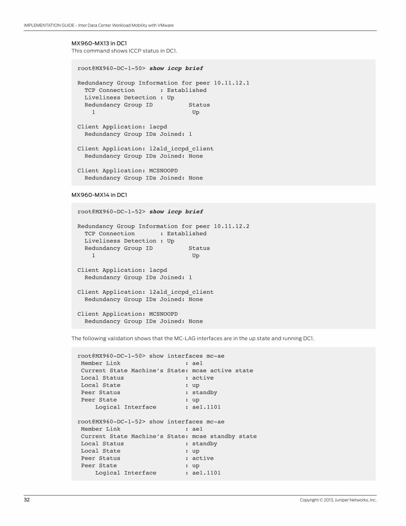
MX960-MX13 in DC1this command shows ICCP status in DC1.
root@MX960-DC-1-50> show iccp brief
Redundancy Group Information for peer 10.11.12.1 TCP Connection : Established Liveliness Detection : Up Redundancy Group ID Status 1 Up
Client Application: lacpd Redundancy Group IDs Joined: 1
Client Application: l2ald_iccpd_client Redundancy Group IDs Joined: None
Client Application: MCSNOOPD Redundancy Group IDs Joined: None
MX960-MX14 in DC1
root@MX960-DC-1-52> show iccp brief
Redundancy Group Information for peer 10.11.12.2 TCP Connection : Established Liveliness Detection : Up Redundancy Group ID Status 1 Up
Client Application: lacpd Redundancy Group IDs Joined: 1
Client Application: l2ald_iccpd_client Redundancy Group IDs Joined: None
Client Application: MCSNOOPD Redundancy Group IDs Joined: None
the following validation shows that the MC-laG interfaces are in the up state and running DC1.
root@MX960-DC-1-50> show interfaces mc-ae Member Link : ae1 Current State Machine’s State: mcae active state Local Status : active Local State : up Peer Status : standby Peer State : up Logical Interface : ae1.1101
root@MX960-DC-1-52> show interfaces mc-ae Member Link : ae1 Current State Machine’s State: mcae standby state Local Status : standby Local State : up Peer Status : active Peer State : up Logical Interface : ae1.1101

Copyright © 2013, Juniper Networks, Inc. 33
IMPLEMENTATION GUIDE - Inter Data Center Workload Mobility with VMware
MX960-MX13 in DC1the following validation shows that the VPlS connection is up and running in DC1 and DC2.
root@MX960-DC-1-50> show vpls connections Instance: DC-VR-1 Local site: DC1-1 (1) connection-site Type St Time last up # Up trans 1 rmt RN 3 rmt Up Aug 15 15:09:08 2011 1 Remote PE: 11.1.1.31, Negotiated control-word: No Incoming label: 262147, Outgoing label: 262145 Local interface: lsi.1049088, Status: Up, Encapsulation: VPLS Description: Intf - vpls DC-VR-1 local site 1 remote site 3
MX960-MX14 in DC1
root@MX960-DC-1-52> show vpls connections Layer-2 VPN connections:Instance: DC-VR-1 Local site: DC1-1 (1) connection-site Type St Time last up # Up trans 1 rmt LN 3 rmt LN
root@MX80-DC-2-130> show vpls connections Layer-2 VPN connections:Instance: DC-VR-1 Local site: DC2-1 (3) connection-site Type St Time last up # Up trans 1 rmt LN 3 rmt LN
MX80-MX24 in DC2
root@MX80-DC-2-131> show vpls connections Layer-2 VPN connections:Instance: DC-VR-1 Local site: DC2-1 (3) connection-site Type St Time last up # Up trans 1 rmt Up Aug 15 20:41:06 2011 1 Remote PE: 10.10.10.50, Negotiated control-word: No Incoming label: 262145, Outgoing label: 262147 Local interface: lsi.1049088, Status: Up, Encapsulation: VPLS Description: Intf - vpls DC-VR-1 local site 3 remote site 1 3 rmt RN
34 Copyright © 2013, Juniper Networks, Inc.
IMPLEMENTATION GUIDE - Inter Data Center Workload Mobility with VMware
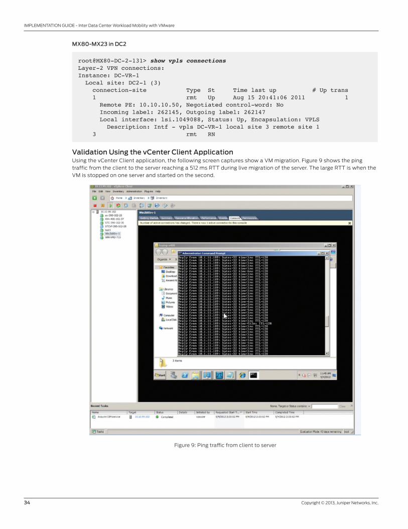
MX80-MX23 in DC2
root@MX80-DC-2-131> show vpls connections Layer-2 VPN connections:Instance: DC-VR-1 Local site: DC2-1 (3) connection-site Type St Time last up # Up trans 1 rmt Up Aug 15 20:41:06 2011 1 Remote PE: 10.10.10.50, Negotiated control-word: No Incoming label: 262145, Outgoing label: 262147 Local interface: lsi.1049088, Status: Up, Encapsulation: VPLS Description: Intf - vpls DC-VR-1 local site 3 remote site 1 3 rmt RN
Validation Using the vCenter Client ApplicationUsing the vCenter Client application, the following screen captures show a VM migration. Figure 9 shows the ping
traffic from the client to the server reaching a 512 ms rtt during live migration of the server. the large rtt is when the
VM is stopped on one server and started on the second.
Figure 9: Ping traffic from client to server
Copyright © 2013, Juniper Networks, Inc. 35
IMPLEMENTATION GUIDE - Inter Data Center Workload Mobility with VMware
8010089-001-eN Jan 2013
Copyright 2013 Juniper Networks, Inc. all rights reserved. Juniper Networks, the Juniper Networks logo, Junos, NetScreen, and ScreenoS are registered trademarks of Juniper Networks, Inc. in the United States and other countries. all other trademarks, service marks, registered marks, or registered service marks are the property of their respective owners. Juniper Networks assumes no responsibility for any inaccuracies in this document. Juniper Networks reserves the right to change, modify, transfer, or otherwise revise this publication without notice.
APAC and EMEA Headquarters
Juniper Networks International b.V.
boeing avenue 240
1119 PZ Schiphol-rijk
amsterdam, the Netherlands
Phone: 31.0.207.125.700
Fax: 31.0.207.125.701
Corporate and Sales Headquarters
Juniper Networks, Inc.
1194 North Mathilda avenue
Sunnyvale, Ca 94089 USa
Phone: 888.JUNIPer (888.586.4737)
or 408.745.2000
Fax: 408.745.2100
www.juniper.net
to purchase Juniper Networks solutions,
please contact your Juniper Networks
representative at 1-866-298-6428 or
authorized reseller.
Printed on recycled paper
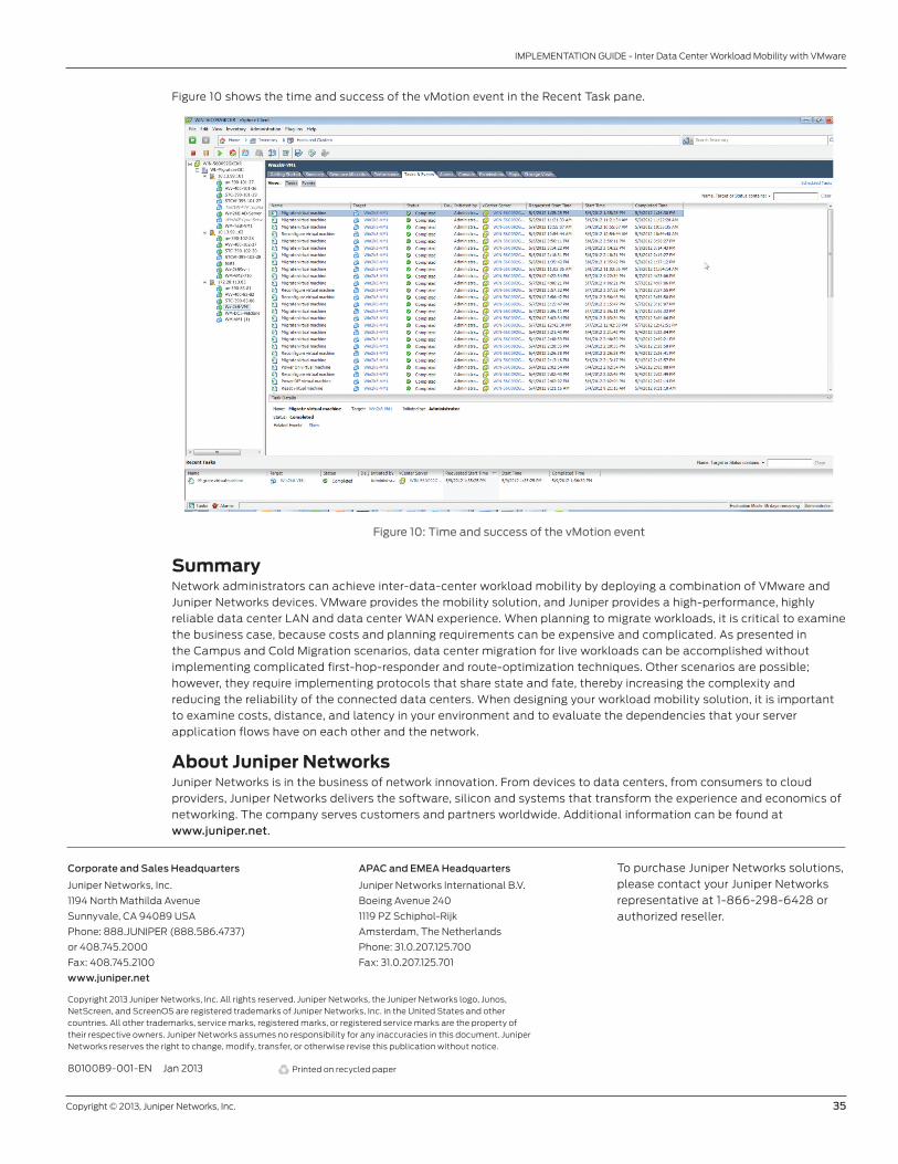
Figure 10 shows the time and success of the vMotion event in the recent task pane.
Figure 10: Time and success of the vMotion event
SummaryNetwork administrators can achieve inter-data-center workload mobility by deploying a combination of VMware and
Juniper Networks devices. VMware provides the mobility solution, and Juniper provides a high-performance, highly
reliable data center laN and data center WaN experience. When planning to migrate workloads, it is critical to examine
the business case, because costs and planning requirements can be expensive and complicated. as presented in
the Campus and Cold Migration scenarios, data center migration for live workloads can be accomplished without
implementing complicated first-hop-responder and route-optimization techniques. other scenarios are possible;
however, they require implementing protocols that share state and fate, thereby increasing the complexity and
reducing the reliability of the connected data centers. When designing your workload mobility solution, it is important
to examine costs, distance, and latency in your environment and to evaluate the dependencies that your server
application flows have on each other and the network.
About Juniper NetworksJuniper Networks is in the business of network innovation. From devices to data centers, from consumers to cloud
providers, Juniper Networks delivers the software, silicon and systems that transform the experience and economics of
networking. the company serves customers and partners worldwide. additional information can be found at
www.juniper.net.