interaction between the artificial vortex and the vortex jet
TRANSCRIPT

Journal of Industrial Aerodynamics, 4(1979) 113--122 113 © Elsevier Scientif ic Publishing Company, Amste rdam -- Printed in The Nether lands
INTERACTION BETWEEN THE ARTIFICIAL VORTEX AND THE VORTEX JET
H.C. CHEN and J.M. CHEN
Power Mechanical En~neering Department, National Tsing-Hua University, Hsinchu, Taiwan 300 (Republic of China)
(Received July 8, 1978)
Summary
A s tudy of a vor tex generator has been made which examines the ef fec t of a vor tex jet which simulates the f low above a hor izonta l turbine located at the th roa t of an inlet that is open at the b o t t o m of the tower. For a s t rong and concentra t ive vor t ex jet, the low- pressure region will no t collapse due to the presence of the turbine.
1. Introduction
For a conventional wind machine system, the maximum power that can be extracted by the turbine from the windstream will be limited by the Betz coef- ficient of 0.593. The long rotating blades of the conventional propeller- or Darrieus-type wind turbines will encounter large dynamic stresses and require increasing stiffness/weight requirements to maintain dynamic stability. In an a t tempt to reduce the size of the turbine wi thout power loss, a variety of wind energy concentrators have been proposed. For example, the application of a wind airfoil in the form of a wind turbine shroud have proven to be capable of reducing the turbine size wi thout power loss.
There are two ways to increase power density: (1) increasing the local wind velocity, and (2) reducing the back pressure of the turbine. The tornado-type wind energy system which is reported by Yen [1] is one of those con- centrators. This system (Fig. 1 ) uses a stationary tower with vertical vanes. The vanes directed the inflow wind so that it had a tangential component to supply circulation. The air exits from the partially opening top of the tower. Then, an internal vortex can be formed by this large hollow tower.
A number of analytical studies of the tornado-like vortex have been in- vestigated by Long [2,3] , Kuo [4], and Chen [5] etc. Experimental studies have been carried out by Ying and Chang [6] who impart the vorticity by rotating a cylindrical hardware cloth screen, and the updraf t is produced by an exhaust fan at the opening of the top hood along the axis of the vortex. The model also serves as an analytical description of certain laboratory vortices

1 1 4
turbine
J
ey
i {::
J jet
Fig. 1. S k e t c h o f ' t o r n a d o - l i k e v o r t e x w i n d e n e r g y s y s t e m ' p r o p o s e d by Y e n [ 1] .
created by electrical discharges such as those produced by Wilkins [7], Ryan and Vonnegut [8], and Watkins [9]. Watts and Chen [10] generate vortices around electrical discharges, the vorticity being provided by a rotating cage. They find that a very long and stable arc can be maintained for long periods when a drum is placed over the top of the centre of the cage to produce a chimney effect.
In the process of extracting power in the region of high velocity and low pressure, if the low-pressure region does not collapse due to the presence of the turbine, then the power output can be increased. In this paper we report re- sults of a mathematical model of swirling flow with a vortex jet which simulates the flow above a horizontal turbine located at the throat of an inlet that is open at the bot tom of tower.
2. Mathematical formulation of the problem
Consider the three-dimensional flow in a tornado-like vortex, with a core region of large vorticity, an outer region where the circulation, F , is constant, and an intensity of the vortex jet. The work presented here is different from other research on buoyancy-driven vortices that currently appears in the litera- ture, that is, a flow through a chimney which is located at the top of the tower.
2.1 Basic equat ions For an incompressible, axisymmetric and steady flow with constant
kinematic viscosity, the component of momentum equations and continuity equation in cylindrical coordinates can be written as follows:
UUr + WUz -- V2 /r = --(l 31 )rip + P[Urr + u r l r - u /r 2 + Uzz] (1)
u(rv)r + w(rv ) z = v[ (rV)rr - (rV)r/r + (rV)zz] (2)
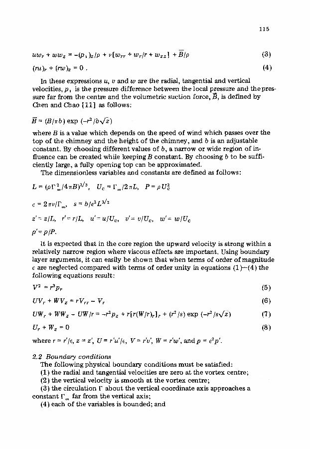
115
m
UWr + WWz = - (P l ) z /P + ~[Wrr + Wr/r + Wzz] + B/p (3)
(ru)r + (rW)z = 0 . (4)
In these expressions u, v and w are the radial, tangential and vertical velocities, P i is the pressure difference between the local pressure and the pres- sure far from the centre and the volumetric suction force, B, is defined by Chen and Chao [11] as follows:
H = ( B / n b ) e x p ( -r2/bx/~)
where B is a value which depends on the speed of wind which passes over the top of the chimney and the height of the chimney, and b is an adjustable constant. By choosing different values of b, a narrow or wide region of in- fluence can be created while keeping B constant. By choosing b to be suffi- ciently large, a fully opening top can be approximated.
The dimensionless variables and constants are defined as follows:
L = ( p F ~ / 4 ~ B ) 2/3, Uc =F /2nL, P = p U ~
e = 2 n v / F , s= b/e2L 3/2
z ' = z / L , r '=r/L, u '=u/Ue, v'= v/Uc, w'= w/Uc
p '=p /P .
It is expected that in the core region the upward velocity is strong within a relatively narrow region where viscous effects are important. Using boundary layer arguments, it can easily be shown that when terms of order of magnitude e are neglected compared with terms of order unity in equations (1)--(4) the following equations result:
V 2 = r3pr
u Y r + WVz = rVrr - Yr
UWr + WWz - UW/r = -r2pz + r[r(W/r)r]r + (r2/s)exp ( - r2 / sv~)
U ~ + W z = O
! - - ! # t ! ! w h e r e r = r / e , z - z , U = r u l e , V =rv,' ' W = r w , a n d p =ezp '.
(5)
(6)
(7)
(8)
2.2 Boundary condit ions The following physical boundary conditions must be satisfied: (1) the radial and tangential velocities are zero at the vortex centre; (2) the vertical velocity is smooth at the vortex centre; (3) the circulation F about the vertical coordinate axis approaches a
constant 1~ far from the vertical axis; (4) each of the variables is bounded; and

116
(5) the vertical and tangential velocities above the turbine are equal to the finite source strength.
Mathematically, these boundary conditions are expressed as:
V(0~) = V(O,z) = W(O,~) = 0
p ( ~ , z ) = w ( , ~ , z ) = o, v ( o o , z ) = 1 (9)
W(r , t ) = g(r) , V ( r , t ) = h ( r )
where g(r) and h ( r ) are t h e given initial profiles, t is the vertical position of the turbine in tower.
2 .3 G o v e r n i n g e q u a t i o n s a n d b o u n d a r y c o n d i t i o n s Let x = r~/2, then equations {5)--(9) can be written as follows:
Ux + w z = 0 (10)
V 2 - 4X2Px = 0 (11)
v v x + w Vz - 2x vx~ = 0 (12)
U w x + WWz + Pz - ( 2 x W x ) x - (l/s) exp ( - 2 x / s v ~ ) = 0 (13)
and the boundary conditions are
U(0,z) = V{0,z) = 0, w x ( O , z ) = finite
p(~o,z) = w ( ~ , z ) = O, Y(cc ,z ) = 1 (14)
w ( x , t ) = V ( x ) , V ( x , t ) = H ( x ) .
3. Solution of the mathematical problem
The approximations for the boundary layer velocity and circulation profiles in the series method are
w = ~ ( z ) [ A ( z ) e -~ + ~ an(Z)pn(~)] n
V = 1 - e -c~ + ~ "6n(Z)t,n(~) n
where ~ = ~, (z)x, c is a constant, the boundary layer profile is described by ~,(z), Vn(~) is called the trial function and Vn (~'), n = 1,2 ...... ,/V, are a countable se to f linearly independent functions defined in a region R. Then, the Gram--Schmit orthonormalization formula is used and defined
1 P yp(~') = ~,_~p ~ gpju j (~) , p = 1 , 2 , . . . (15)
1=1

117
are the corresponding orthonormalized function from vn. The formulae for the orthonormalization coefficients gpj and Hp are
gpp = 1, p = 1 , 2 , . . . , N
a l l a21 • • • a p - l , 1
521 522 • . . 5 p - - 2 , 2
a p - l ~ l
and
• . . a p - l , p - ,
- - g p , - ]
= ( - 1 )
apl
ap~
_ap,p_ , '
(16)
p Hp=Z; gp ,,j
j = l
where
amn = fR PmPndR "
Let the trial function ~k(~) be ~e -(k+l)~, k = 1 , 2 , . . . , N, which will force the velocities to satisfy the boundary conditions along the x-axis. After the Gram-- Schmit orthonormalization formula is used, equation (15) can be wri t ten as follows:
p
yp = (z/,4Y~) k=1
gpk~e-(k+l)~, p = 1 , 2 , . . . , N .
The boundary layer velocity profiles in exponential series will be
w = X ( z ) [ A ( z ) e -~ + ~ an(z)Yn(~)] n
(17)
V = 1 - e -c~ + ~ b n ( z ) y n ( I ) . n
Now substitute equation (17) into equation (10), to give
(18)
U = .4 (e -~" - 1 ) - (~A/ ;~ )~ .e . ~" + ~ (anN'-Hn) ~ gnk(~e-gr/g n k
+ e-g~/g a - l l g 2 ) - ~ ( ~ a n l k ~ / - ~ n ) ~ gnk~2e -gr n k
(19)

118
N n
w h e r e ( ' ) = d ( ) / d z , g = k + l , ~ = ~ , ~ = n n--1 k k=l
be rearranged to give
L,(U, V, w) = UVx + w V z - 2xVxx =0
L2 (U, V, w) = Uwxx + WWzx - (2XWx)xx + VVz/2x2
+ (2/s2x/~)exp (-2x/s~Z-z)= 0
. Equations (10)--(13) can
(20)
(21)
3.1 Galerkin and subdomain methods The (2N + 2) unknown coefficients an, bn, ~ and A in the velocity approx-
imations are here determined by requiring the integral of the weighted differ- ence between exact and approximate velocity profiles over the region (0,~) to vanish for (N + 1) different choices of weighting functions.
The Galerkin method consists of obtaining the coefficients of a series expan- sion regarded as an approximate solution to a differential equation, by minimiz ing the residual using orthogonality conditions. Therefore, the weighting func- tion will be chosen as the orthonormalized trial functions. Then, the Galerkin equations will be
f o
L1 (U, V, W)ypdx = 0
f L2(U, V, W)ypdx = 0, p = 1,2 . . . . . N .
o
The subdomain method is used to obtain the coefficients of a series expan- sion regarded as an approximate solution to a differential equation, but the differential equation is satisfied on average in a subdomain. In here, the weight- ing function will be chosen as
wi = 1 , for a l l x i n R .
These lead to (2N + 2) first-order ordinary differential equations for the parameters an(Z), bn (z ), X (z ) and A (z ). They have the form
~ E i , nan + ~ E i , N+nb n +Ei, 2N+IA +Ei, 2N+2~ = F i n n
(22)
~ E N + l +i, nan + ~ EN + l +i,N +nbn + EN + I +i,2N + I[4 n n
+ EN+I+i,2N+2 ~ = FN+I+ i (23)
where n = 1 , 2 , . . . , N , i = 1,2, . . . . (N + 1). The coefficients E and F are func- tions of N, gij, Hi and c. The details of the operations have been given by Chen [12].

119
3.2 The initial ve loc i ty prof i les along the z-axis The velocity profiles w, V and U satisfy the boundary conditions along the
x-coordinate. Let the conditions in the z-direction be
G(x) = w(x , t ) = X ( t } A ( t ) e x p [ - r ,~ (x , t ) ]
H(x) = V(x , t ) = 1 - exp [ -cr2~(x, t ) ]
where r~ and r2 are constants. This initial vertical velocity profile displays an axial mass-flow rate property that
Qaxial = f XA exp (-rl~)2nrdr = 2 n A ( t ) / r l .
Therefore, A (t) can be chosen to fit the axial mass-flow rate, and X ( t )A( t ) is equivalent to the initial vertical velocity along the axis o f the vortex. Then,
12
an(t) = ( A / ~ n ) ~ _ j gnh[ ( l lg + r, )2 _ ( l l g + 1) 2 ] k
n
b n (t) = ( 1 / V ~ n ) ~ gnk [(1/g + c) 2 - ( l / g + cr2) 2] . k
(24)
The (2N. + 2) first-order ordinary differential equations (22) and (23) can be solved for an, bn, X and A by standard procedures such as the Runge--Kutta method.
4. Results
In the paper, the problem is solved by the method of weighted residuals (Galerkin and subdomain methods). Fig. 2 shows the mean square errors for
.06
,O4
E 1
.02
z=O L k(fl~O, s=25
0.5
N
40
E 2
24
x(~}= .5 z---O
2 3 L 5 N
Fig. 2. Mean square error in the approximation of the velocity profiles for the apparent convergence by the exponential series.

120
the apparent convergence o f these quantit ies for increas ingN. It is f o u n d that the so lut ion will converge very well. Therefore, le t N be 3 for all various parameters.
Equat ions (22) and (23) were solved for several values o f parameters X (t), A ( t ) , rl and r2 with s = 25 , c = 1, N = 3 and t = 0 . 0 0 0 1 . In Fig. 3, the vertical ve loc i ty , tangential ve loc i ty , pressure and circulat ion are p lo t ted against the variable ~ for the various heights. Figs. 4 to 8 s h o w the pressure differences and vertical velocit ies a long the centre l ine o f the vortex , boundary layer thick- ness funct ion , and the radial velocit ies far from the vortex core p l o t t e d against the independent variable z . Results o f c o m p u t a t i o n s for these quantit ies are s h o w n as fo l lows: A = 10, rr = r2 = 1 .01 and X = 0 .5 , 2, 5, 8 in Fig. 4; X = 0 .5 , r~ = r2 = 1.01 and A = 2, 4, 6, 8, 10, 12 in Fig. 5 ;XA = 5, r~ = r2 = 1 .01 and X = 1 /8 , 1 /2 , 2, 8 in Fig. 6; k = 0 .5 , A = 10, r2 = 1 .01 and rl = 2, 1 .01 , 0 . 75 in Fig. 7; X = 0 .5 , A = 10, r~ = 1 .01 and r2 = 2, 1 .5 , 1 .01 , 0 .75 in Fig. 8.
Alt)=lO, s=25 X(t)=.5
v - p
4.0 .20
2.4
v
5 z : O . V
3 .12
3
1 0.8 .04 2
1 2 3 4 5 1 2 3 4 5
• /-~r ~,~r
Fig. 3. Velocities, circulation and pressure in the vortex.
3.5
2.5
( ' P ) a x
1.5
0.5
1 2 3 z
6 120
WmQ x ' "~
6
4 80
2 40~
1 2 3 4 z
6
-U}ma x
Fig. 4. Pressure, boundary layer thickness profile, velocities with various ~,(t) in thevortex.

121
.20 (-D~a ×
.12
.0z
. . . . .
Xlt)=.5 s= ~-T~
A ~ t ~ 6 /~ s l
Z
wmc
12 6
"" 12
.2 - - -7."
1 2 3 4 5 z
-u) max
4
Fig. 5. Pressure, boundary layer thickness profile, velocit ies wi th various A(t) in the vortex.
X[t)Ait)= 5,s =25 1,2
.4
12 6
& Wmax
8 4
4 2
I18 U
8
z z
6
~-U} mQx
Fig. 6. Pressure, boundary layer thickness profile, velocities with XA = 5.
.2~ (-P)rnax
.16
.08
. :25 x(fl =05 A(t}=10 S =,/ '~
8
035 z.
~ x 2.o0
I 2 3 z. 5 I 2 3 4 z z
'I-Uima x
4
l~g. 7. Pressure, boundary layer thickness profile, velocities with various r I in the vortex.

122
.36
(-P~no×
.2z
s =25 8=~7"~ • Xlt/=05 /
,W L \ \ 2o0 2-1.5
z
w~o~ 8
4 Z,
2 2
.0.75
075 1.01 1.50
J r
Z
6
- i_U)rnox
Fig. 8. Pressure, boundary layer thickness profile, velocities with various r 2 in the vortex.
5. Conclusion
A study of a wind energy generator has been made to examine the effect of a vortex jet which simulates the f low above a horizontal turbine. Using the Galerkin and subdomaln methods to get an approximate solution. The results of the present investigation show that: (1) under the same circulation distribu- tion with a strong and concentrative axial mass-flow rate above the turbine, a stable and concentrative vortex is induced, (2) under the same axial velocity distribution with a concentrative circulation, a higher pressure drop in the vortex core is produced, and (3) the width of the axial and tangential velocities above the turbine will affect the vortex. The vortex will approach an unstable state as the width decreases.
References
1 J.T. Yen, Tenth. Intersociety Energy Conversion EngineeringConf., IEEE Catalog No. 75 CH0 983-7 TAB., 1975.
2 R.R. Long, J. Meteorol., 15 (1958) 108--112. 3 R.R. Long, J. Fluid Mech., 11 (1961) 611--623. 4 H.L. Kuo, J. Atmos. Sci., 23 (1966) 25--42. 5 J.M. Chen, Dr Eng. Dissertation, Tulane University, New Orleans, La., 1974. 6 S.J. Ying and C.C. Chang, J. Atrnos. Sci., 27 (1970) 1--14. 7 E. Wilkins, J. Geophys. Res., 69 (1964) 2435--2447. 8 R.T. Ryan and B. Vonnegut, Science, 168 (1970) 1349--1351. 9 D. Watkins, Ph.D. Dissertation, SUNY--Albany, 1975.
10 R.G. Watts and J.M. Chen, Annual Report, NSF Grant GK-35993, 1974. 11 J.M. Chen and H.H. Chao, Annual Report, National Tsing Hua University PME-01,
1977. 12 H.C. Chen, M.S. Thesis, National Tsing Hua University, Taiwan, 1978.