interactive fractal viewer csee w4840 final reportsedwards/classes/2012/4840/reports/...interactive...
TRANSCRIPT

Interactive Fractal Viewer
CSEE W4840 Final Report
Nathan Hwang - [email protected] Richard Nwaobasi - [email protected] Pena - [email protected] Stephen Pratt - [email protected]
Advisor: Prof. Stephen Edwards
May 11, 2012
1

Abstract
Fractals are often appreciated for their rich and elegant internal complexity. It is this complexitythat is responsible for the beautiful aesthetic of these famed mathematical images as well as the amountof computational power required to generate them. Using fixed point calculations within parallelizedsequential logic blocks, we aim to develop an hardware-accelerated fractal generator, capable of computingand displaying quadratic Julia sets in significantly less time than a software-based solution.
1 Background
1.1 An Introduction to Julia sets
The Julia set J of a complex rational function f : C→ C is can be expressed as:
∀z : limn→∞
|fn(z)| =∞
That is, given a function that describes a mapping from the complex numbers to the complex numbers,that function’s Julia set is the set of numbers for which repeated application of that function results inconvergence towards infinity. Julia sets have many remarkable properties. Iterations of a function ischaotic on its Julia set, meaning that it represents a dynamical system in which tiny perturbationsin initial conditions can result in disproportionately large changes in the evolution of the system. Aschaotic systems, they can be used to generate pseudo-random numbers. When plotted, Julia sets havethe capacity to produce stunning images.
Quadratic polynomial Julia sets are Julia sets of functions that take the form
fc(z) = z2 + c
So any given quadratic polynomial Julia set is uniquely described by some point on the complex planec. These sets produce fractals, and so they often exhibit self-similarity. Quadratic polynomial Julia setshave the nice property that the magnitude of fc(z) at any point in a recurrence whose initial value wasnot in the Julia set will always be bounded above by 2. Thus, any point z that causes |fc(zi)| > 2 forany zi in the recurrence is necessarily not a member of J(fc)
Generating Quadratic Polynomial Julia Sets
Because points not belonging to the Julia set of some quadratic polynomial fc (also called points in theFatou set of fc) are guaranteed to be bounded in magnitude by 2 during repeated application of fc, onemay generate the Julia set for a given window in fc by sampling the members of that window, repeatedlyapplying fc, and testing whether or not the magnitude ever breaks away from 2, giving up after somefixed number of iterations. This is the basic design of the Interactive Fractal Viewer.
When plotting the resulting Julia set, one may choose to colorize the image based on how long ittook for the iteration beginning at each point in the complex plane to become unbounded. We shallhenceforth call this value the breakaway iteration, or k. Thus, the problem of plotting a Julia set on ascreen reduces to computing the viewing window as a section of the complex plane, and finding k foreach sample point in that section.
Generating Julia sets in this fashion can be a very lengthy process, especially when the points mustbe done in series. However, since each recurrence to be tested is completely independent of each other,the problem is extraordinarily parallelizeable. Furthermore, since the function being applied is relativelysimple, it may be very easily implemented in hardware. Giving the Interactive Fractal Viewer itsmotivation.
2
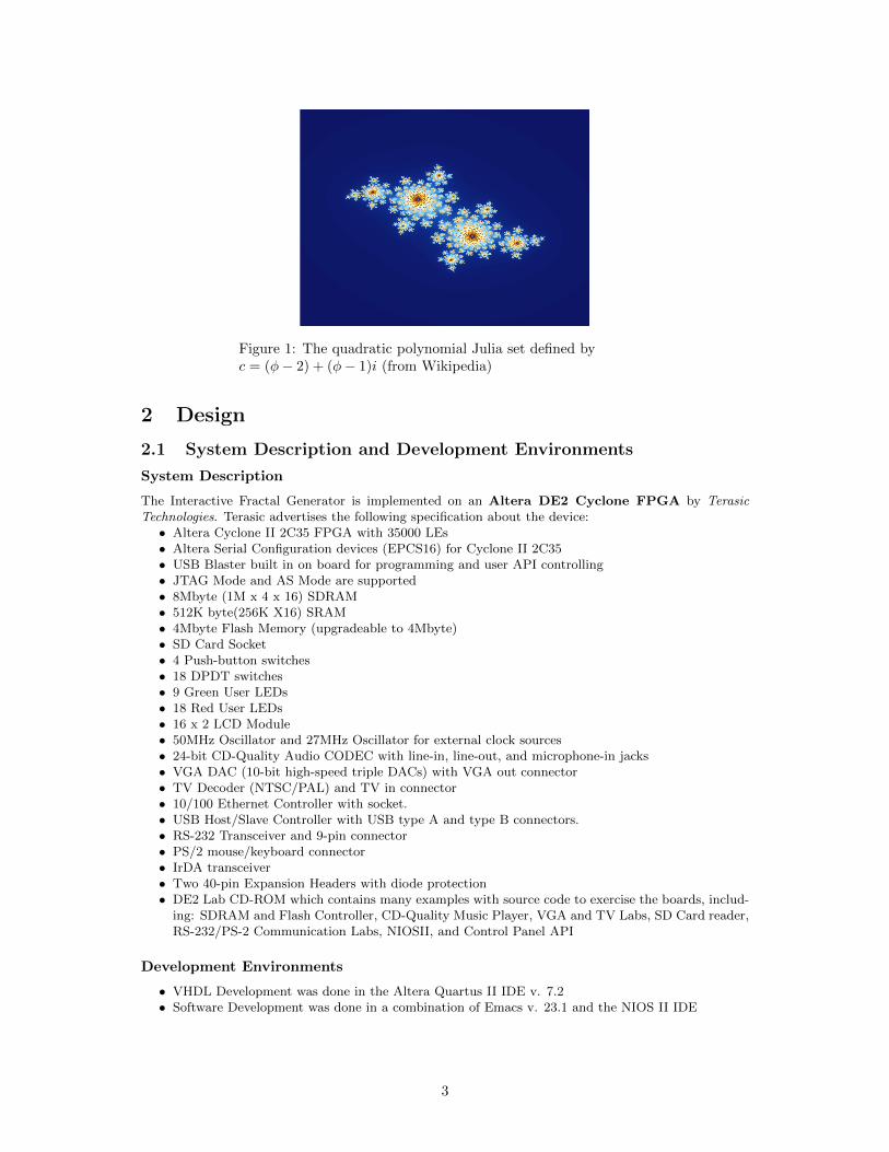
Figure 1: The quadratic polynomial Julia set defined byc = (φ− 2) + (φ− 1)i (from Wikipedia)
2 Design
2.1 System Description and Development Environments
System Description
The Interactive Fractal Generator is implemented on an Altera DE2 Cyclone FPGA by TerasicTechnologies. Terasic advertises the following specification about the device:• Altera Cyclone II 2C35 FPGA with 35000 LEs• Altera Serial Configuration devices (EPCS16) for Cyclone II 2C35• USB Blaster built in on board for programming and user API controlling• JTAG Mode and AS Mode are supported• 8Mbyte (1M x 4 x 16) SDRAM• 512K byte(256K X16) SRAM• 4Mbyte Flash Memory (upgradeable to 4Mbyte)• SD Card Socket• 4 Push-button switches• 18 DPDT switches• 9 Green User LEDs• 18 Red User LEDs• 16 x 2 LCD Module• 50MHz Oscillator and 27MHz Oscillator for external clock sources• 24-bit CD-Quality Audio CODEC with line-in, line-out, and microphone-in jacks• VGA DAC (10-bit high-speed triple DACs) with VGA out connector• TV Decoder (NTSC/PAL) and TV in connector• 10/100 Ethernet Controller with socket.• USB Host/Slave Controller with USB type A and type B connectors.• RS-232 Transceiver and 9-pin connector• PS/2 mouse/keyboard connector• IrDA transceiver• Two 40-pin Expansion Headers with diode protection• DE2 Lab CD-ROM which contains many examples with source code to exercise the boards, includ-
ing: SDRAM and Flash Controller, CD-Quality Music Player, VGA and TV Labs, SD Card reader,RS-232/PS-2 Communication Labs, NIOSII, and Control Panel API
Development Environments
• VHDL Development was done in the Altera Quartus II IDE v. 7.2• Software Development was done in a combination of Emacs v. 23.1 and the NIOS II IDE
3
2.2 High-level Overview
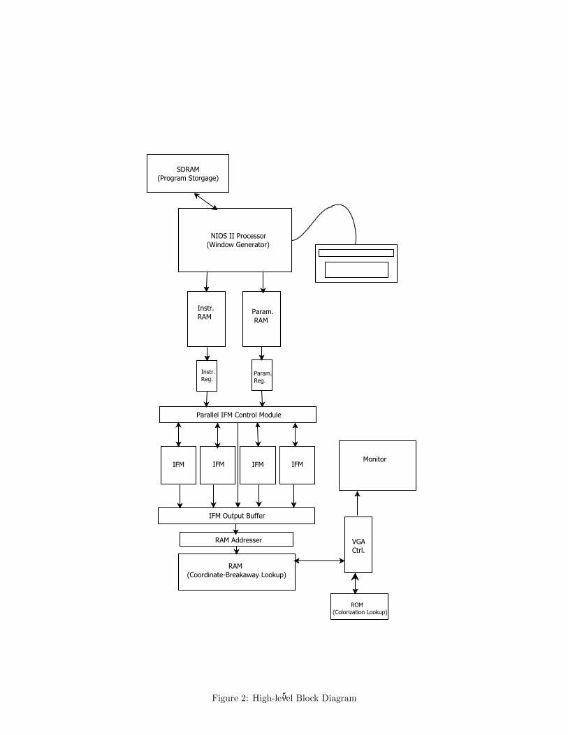
The following is a description of how data travels through the block structure specified in Figure 2 whengenerating a single fractal.• Data flow originates from the NIOS II Processor, which initializes the system by computing a set
of parameters that can be used to describe the target window and fractal. The NIOS writes theseparameters across the Avalon Bus onto an on-board RAM and sends instructions to generate anew image to a special instruction register.
• When the instruction register receives the generate signal, it tells a component charmingly referredto as the Rammer to write the parameters information contained in the RAM into registers. Itthen asserts a generate signal that will be read by the Window Generator
• The Window Generator takes these parameters as input and builds a set of 4-tuples (x, y, a, b)where each tuple is a mapping from a VGA coordinate (x, y) to a value in the complex plane ofthe form a + bi. The (a, b) values eventually be used to compute a breakaway count k for eachco-ordinate on the screen. The computation will be performed by a specialized component calledan Iterative Function Module, or IFM.
• Before the next (a, b, x, y) tuple is delivered to one of the 4 available IFMs, it must be requested by acomponent known as the IFM Controller. The IFM Controller is responsible for distributingwork among several IFMs working in parallel.
• When an IFM enters a ready state, it is given the next (a, b, x, y) tuple and will begin performing thefunction iterations using the constant prescribed by the set to be generated. The IFM transitionsinto a done state after a fixed number of iterations, or when the squared magnitude of its currentiteration exceeds 4.
• The IFM Controller takes the data given by the done-state IFMs and writes it to a queue thatwill deliver it to the Coordinate-Breakaway Lookup Table, implemented using the on-boardSRAM. The IFM data takes the form of the (x, y, k) triples we set out to create. The k value ofeach triple is stored in the Coordinate-Breakaway Lookup Table at an address determined bythe (x, y) values. In this way, we map VGA coordinates to their associated breakaway iterations.
• The VGA Module fetches results from the Coordinate-Breakaway Lookup Table and col-orizes them using a separate ROM-based Colorization Lookup Table. The ColorizationLookup Table takes a breakaway count, k, and maps it to an (r, g, b) bit-vector for use by theVGA.
2.3 Module Implementation
User Interface Module
As an interactive device, our fractal generator has the capacity to accept user parameters such as windowsize or Julia set constants during operation. This communication with the user is facilitated by the NIOSII Processor taking PS/2 keyboard input. We refer to these entities and all their supporting devicesas the User Interface Module. This module is responsible for handling communication with inputperipherals and translating user input into information that can easily be used by the hardware-basedfractal generator. Once this information has been translated into a set of values that can be used by theremainder of the system generator, they are written into an on-board RAM. When the User InterfaceModule is ready for the hardware to take some action, it sends a signal to a component on the board,which forwards the signal appropriately. All communication with the board is performed over the AvalonInterconnect Fabric.
The NIOS II Processor uses the SDRAM as its memory store.Parameters of primary concern are those of viewing window and Julia set constant. The window is
set using the following values (which will be elaborated on in the Window Generator section):- amin 36 bits- adiff 36 bits- aleap 10 bits- bmin 36 bits- bdiff 36 bits- bleap 10 bits
Meanwhile, the Julia set constant is set using the following values- creal 36 bits- cimg 36 bits
4
NIOS II Processor(Window Generator)
SDRAM(Program Storgage)
Instr.RAM
Param. RAM
Instr.Reg.
Param.Reg.
Parallel IFM Control Module
IFM IFM IFM IFM
IFM Output Buffer
RAM Addresser
RAM(Coordinate-Breakaway Lookup)
VGACtrl.
ROM(Colorization Lookup)
Monitor
Figure 2: High-level Block Diagram5
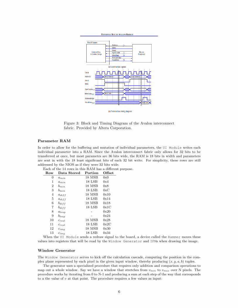
Figure 3: Block and Timing Diagram of the Avalon interconnectfabric. Provided by Altera Corporation.
Parameter RAM
In order to allow for the buffering and mutation of individual parameters, the UI Module writes eachindividual parameter into a RAM. Since the Avalon interconnect fabric only allows for 32 bits to betransferred at once, but most parametrs are 36 bits wide, the RAM is 18 bits in width and parametersare sent in with the 18 least significant bits of each 32 bit write. For simplicity, these rows are stilladdressed by the NIOS as if they were 32 bits wide.
Each of the 14 rows in this RAM has a different purpose.Row Data Stored Portion Offset
0 amin 18 MSB 0x01 amin 18 LSB 0x42 bmin 18 MSB 0x83 bmin 18 LSB 0xC4 adiff 18 MSB 0x105 adiff 18 LSB 0x146 bdiff 18 MSB 0x187 bdiff 18 LSB 0x1C8 aleap - 0x209 bleap - 0x24
10 creal 18 MSB 0x2811 creal 18 LSB 0x2C12 cimg 18 MSB 0x3013 cimg 18 LSB 0x34
When the UI Module sends a redraw signal to the board, a device called the Rammer moves thesevalues into registers that will be read by the Window Generator and IFMs when drawing the image.
Window Generator
The Window Generator serves to kick off the calculation cascade, computing the position in the com-plex plane represented by each pixel in the given input window, thereby producing (x, y, a, b) tuples.
The generator uses a specialized procedure that requires only addition and comparison operations tomap out a whole window. Say we have a window that stretches from vmin to vmax over N pixels. Theprocedure works by iterating from 0 to N-1 and producing a sum at each step of the way that correspondsto a the value of v at that point. The procedure requires a few values as input:
6
36
36
10
36
10
clk
next_val
reset
a_min
a_diff
a_leap
a_out
x_out
Window Generator
36
36
10
a_min
a_diff
a_leap
36 b_out
10 y_out
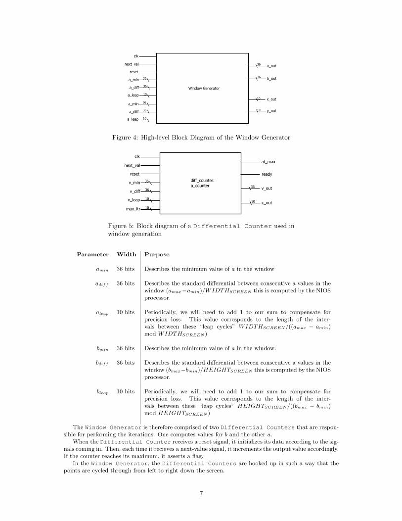
Figure 4: High-level Block Diagram of the Window Generator
36
36
10
10
36
10
clk
next_val
reset
v_min
v_diff
v_leap
max_itr
at_max
ready
v_out
c_out
diff_counter:a_counter
Figure 5: Block diagram of a Differential Counter used inwindow generation
Parameter Width Purpose
amin 36 bits Describes the minimum value of a in the window
adiff 36 bits Describes the standard differential between consecutive a values in thewindow (amax−amin)/WIDTHSCREEN this is computed by the NIOSprocessor.
aleap 10 bits Periodically, we will need to add 1 to our sum to compensate forprecision loss. This value corresponds to the length of the inter-vals between these “leap cycles” WIDTHSCREEN/((amax − amin)mod WIDTHSCREEN )
bmin 36 bits Describes the minimum value of a in the window.
bdiff 36 bits Describes the standard differential between consecutive a values in thewindow (bmax−bmin)/HEIGHTSCREEN this is computed by the NIOSprocessor.
bleap 10 bits Periodically, we will need to add 1 to our sum to compensate forprecision loss. This value corresponds to the length of the inter-vals between these “leap cycles” HEIGHTSCREEN/((bmax − bmin)mod HEIGHTSCREEN )
The Window Generator is therefore comprised of two Differential Counters that are respon-sible for performing the iterations. One computes values for b and the other a.
When the Differential Counter receives a reset signal, it initializes its data according to the sig-nals coming in. Then, each time it recieves a next-value signal, it increments the output value accordingly.If the counter reaches its maximum, it asserts a flag.
In the Window Generator, the Differential Counters are hooked up in such a way that thepoints are cycled through from left to right down the screen.
7
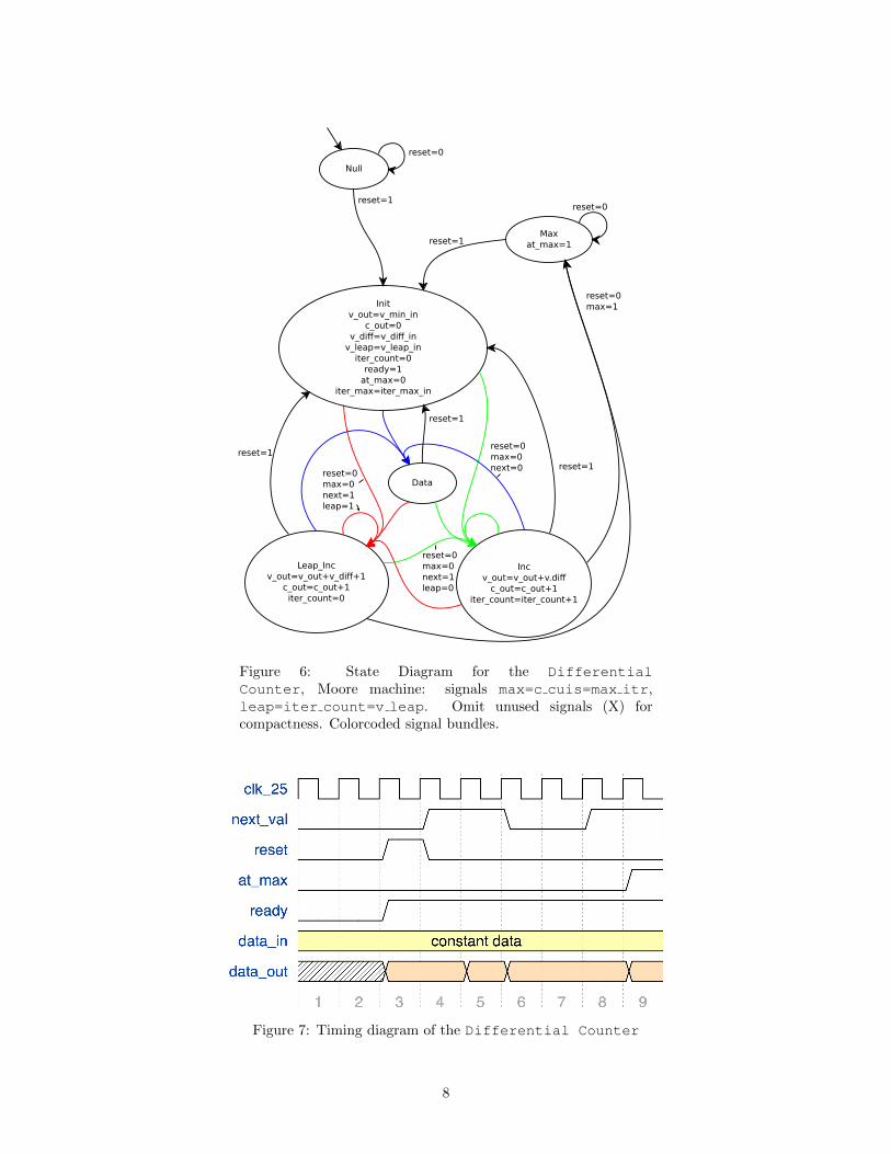
Null
Initv_out=v_min_in
c_out=0v_diff=v_diff_inv_leap=v_leap_initer_count=0ready=1at_max=0
iter_max=iter_max_in
reset=0
reset=1
Maxat_max=1
Data
Incv_out=v_out+v.diffc_out=c_out+1
iter_count=iter_count+1
Leap_Incv_out=v_out+v_diff+1
c_out=c_out+1iter_count=0
reset=0
reset=1
reset=1
reset=1
reset=1
reset=0max=1
reset=0max=0next=1leap=0
reset=0max=0next=1leap=1
reset=0max=0next=0
Figure 6: State Diagram for the DifferentialCounter, Moore machine: signals max=c cuis=max itr,leap=iter count=v leap. Omit unused signals (X) forcompactness. Colorcoded signal bundles.
Figure 7: Timing diagram of the Differential Counter
8
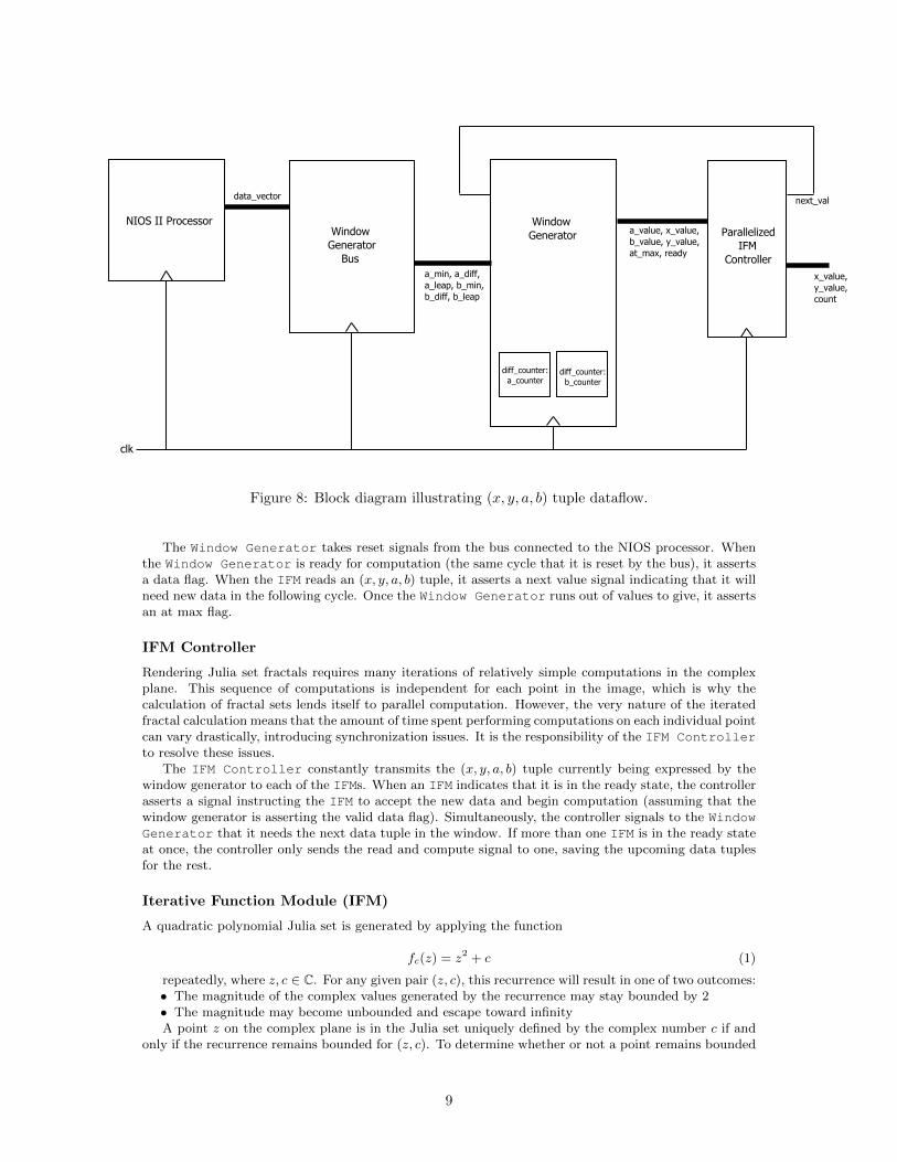
NIOS II Processor Window Generator Bus
WindowGenerator
diff_counter: a_counter
diff_counter: b_counter
Parallelized IFM Controller
data_vector
a_min, a_diff,a_leap, b_min,b_diff, b_leap
a_value, x_value,b_value, y_value,at_max, ready
x_value,y_value,count
next_val
clk
Figure 8: Block diagram illustrating (x, y, a, b) tuple dataflow.
The Window Generator takes reset signals from the bus connected to the NIOS processor. Whenthe Window Generator is ready for computation (the same cycle that it is reset by the bus), it assertsa data flag. When the IFM reads an (x, y, a, b) tuple, it asserts a next value signal indicating that it willneed new data in the following cycle. Once the Window Generator runs out of values to give, it assertsan at max flag.
IFM Controller
Rendering Julia set fractals requires many iterations of relatively simple computations in the complexplane. This sequence of computations is independent for each point in the image, which is why thecalculation of fractal sets lends itself to parallel computation. However, the very nature of the iteratedfractal calculation means that the amount of time spent performing computations on each individual pointcan vary drastically, introducing synchronization issues. It is the responsibility of the IFM Controllerto resolve these issues.
The IFM Controller constantly transmits the (x, y, a, b) tuple currently being expressed by thewindow generator to each of the IFMs. When an IFM indicates that it is in the ready state, the controllerasserts a signal instructing the IFM to accept the new data and begin computation (assuming that thewindow generator is asserting the valid data flag). Simultaneously, the controller signals to the WindowGenerator that it needs the next data tuple in the window. If more than one IFM is in the ready stateat once, the controller only sends the read and compute signal to one, saving the upcoming data tuplesfor the rest.
Iterative Function Module (IFM)
A quadratic polynomial Julia set is generated by applying the function
fc(z) = z2 + c (1)
repeatedly, where z, c ∈ C. For any given pair (z, c), this recurrence will result in one of two outcomes:• The magnitude of the complex values generated by the recurrence may stay bounded by 2• The magnitude may become unbounded and escape toward infinityA point z on the complex plane is in the Julia set uniquely defined by the complex number c if and
only if the recurrence remains bounded for (z, c). To determine whether or not a point remains bounded
9
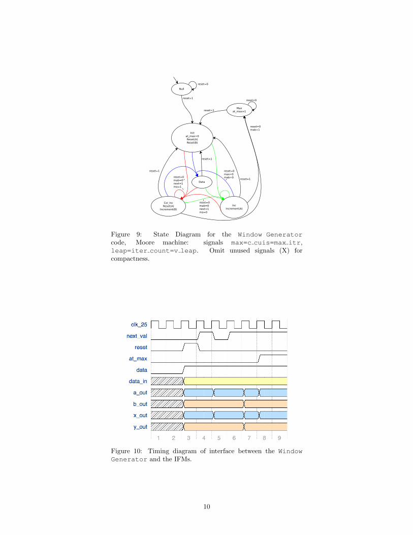
Null
Initat_max=0Reset(A)Reset(B)
reset=0
reset=1
Maxat_max=1
Data
Incincrement(A)
Col_IncReset(A)
Increment(B)
reset=0
reset=1
reset=1
reset=1
reset=1
reset=0mab=1
reset=0mab=0next=1ma=0
reset=0mab=0next=1ma=1
reset=0max=0mab=0
Figure 9: State Diagram for the Window Generatorcode, Moore machine: signals max=c cuis=max itr,leap=iter count=v leap. Omit unused signals (X) forcompactness.
Figure 10: Timing diagram of interface between the WindowGenerator and the IFMs.
10
IFM
IFM
IFM
IFM
IFM
CONTROLLER
a, b, x, y
a, b, x, y
a, b, x, y
a, b, x, y
x, y, count
x, y, count
x, y, count
x, y, countx, y,count, we
a, b,x, y,at_max,ready
clk
MUXRegister
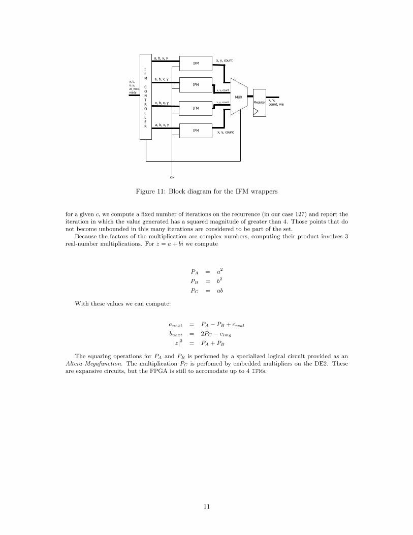
Figure 11: Block diagram for the IFM wrappers
for a given c, we compute a fixed number of iterations on the recurrence (in our case 127) and report theiteration in which the value generated has a squared magnitude of greater than 4. Those points that donot become unbounded in this many iterations are considered to be part of the set.
Because the factors of the multiplication are complex numbers, computing their product involves 3real-number multiplications. For z = a+ bi we compute
PA = a2
PB = b2
PC = ab
With these values we can compute:
anext = PA − PB + creal
bnext = 2PC − cimg
|z|2 = PA + PB
The squaring operations for PA and PB is perfomed by a specialized logical circuit provided as anAltera Megafunction. The multiplication PC is perfomed by embedded multipliers on the DE2. Theseare expansive circuits, but the FPGA is still to accomodate up to 4 IFMs.
11
Reset
Wait Compute
Donex,y,count
reset=1
reset=0
reset=0
compute=1
compute=1
count=127 or ma2 > 4
reset=0
reset=1
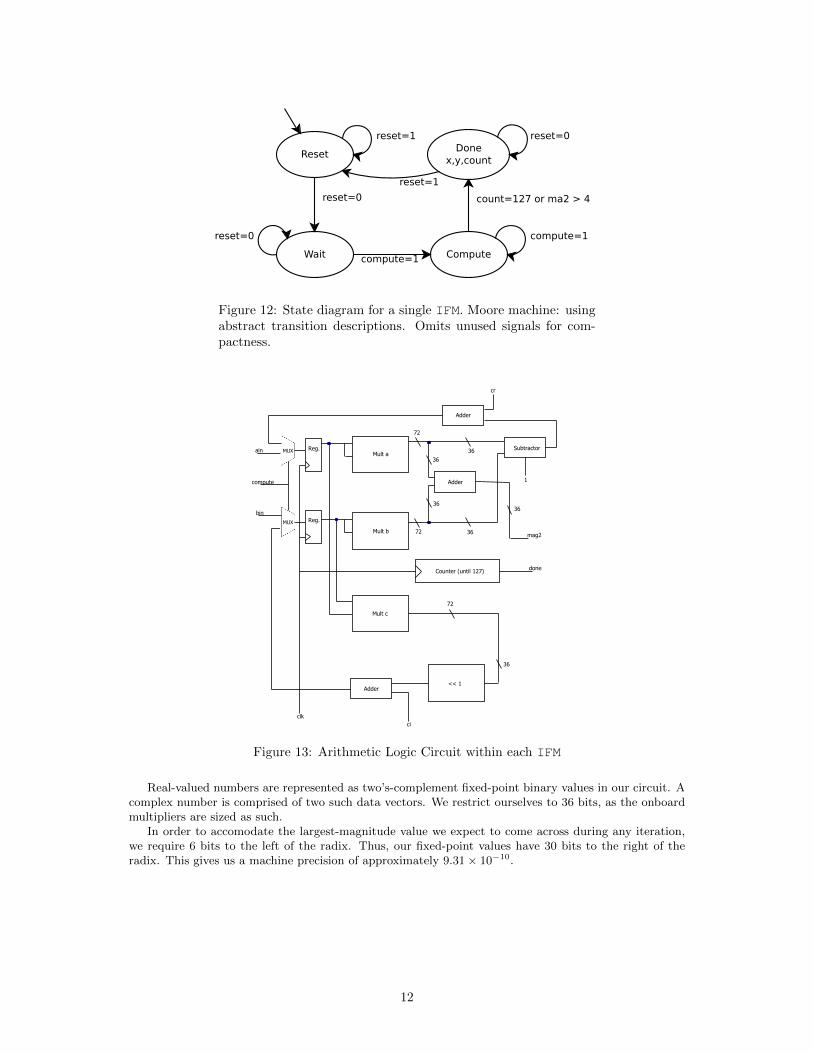
Figure 12: State diagram for a single IFM. Moore machine: usingabstract transition descriptions. Omits unused signals for com-pactness.
compute
ain
bin
cr
ci
1
mag2
Mult a
Mult b
Mult c
Adder
Adder
Adder
Subtractor
<< 1
36
36
36
36
36
36
72
72
72
Counter (until 127) done
Reg.
Reg.
MUX
MUX
clk
Figure 13: Arithmetic Logic Circuit within each IFM
Real-valued numbers are represented as two’s-complement fixed-point binary values in our circuit. Acomplex number is comprised of two such data vectors. We restrict ourselves to 36 bits, as the onboardmultipliers are sized as such.
In order to accomodate the largest-magnitude value we expect to come across during any iteration,we require 6 bits to the left of the radix. Thus, our fixed-point values have 30 bits to the right of theradix. This gives us a machine precision of approximately 9.31× 10⁻¹⁰.
12
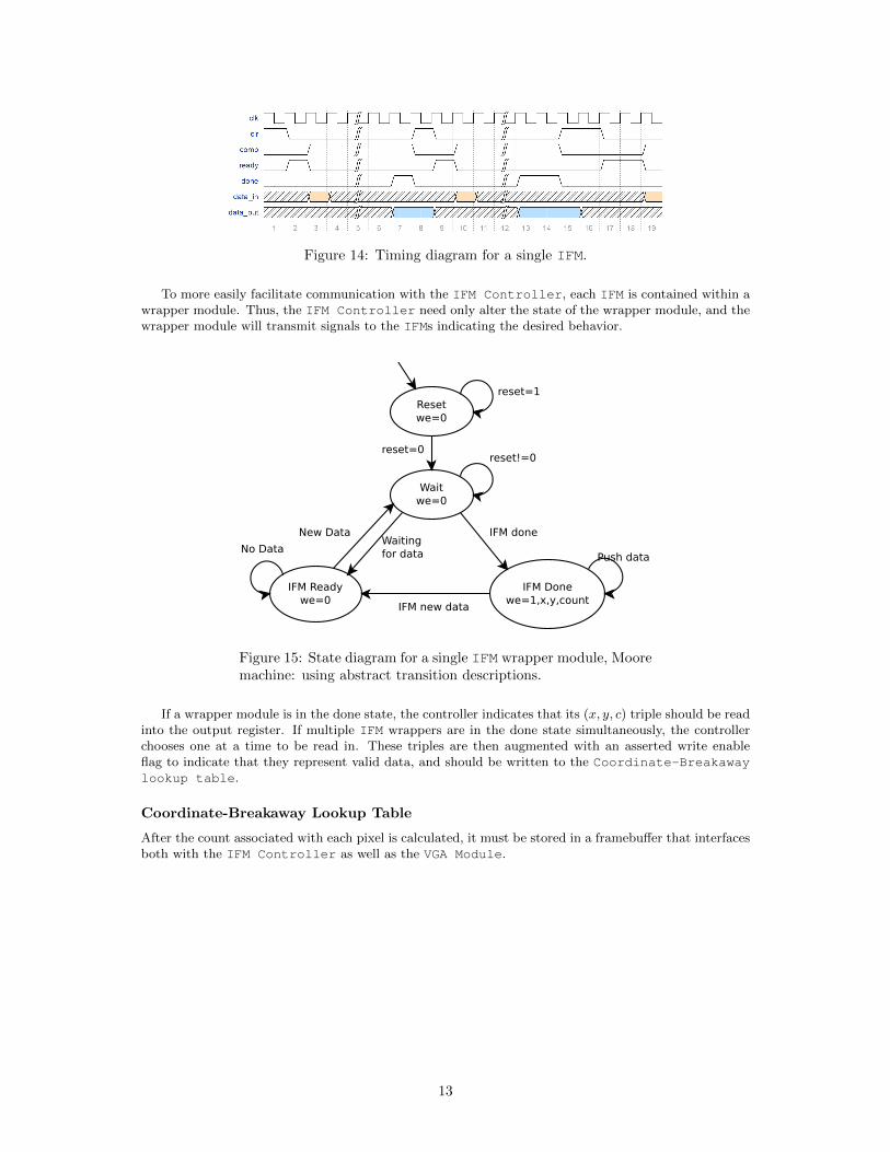
Figure 14: Timing diagram for a single IFM.
To more easily facilitate communication with the IFM Controller, each IFM is contained within awrapper module. Thus, the IFM Controller need only alter the state of the wrapper module, and thewrapper module will transmit signals to the IFMs indicating the desired behavior.
Resetwe=0
Waitwe=0
IFM Readywe=0
IFM Donewe=1,x,y,count
reset=1
reset=0reset!=0
IFM new data
IFM done
Push dataNo Data
New DataWaitingfor data
Figure 15: State diagram for a single IFM wrapper module, Mooremachine: using abstract transition descriptions.
If a wrapper module is in the done state, the controller indicates that its (x, y, c) triple should be readinto the output register. If multiple IFM wrappers are in the done state simultaneously, the controllerchooses one at a time to be read in. These triples are then augmented with an asserted write enableflag to indicate that they represent valid data, and should be written to the Coordinate-Breakawaylookup table.
Coordinate-Breakaway Lookup Table
After the count associated with each pixel is calculated, it must be stored in a framebuffer that interfacesboth with the IFM Controller as well as the VGA Module.
13
Coordinate-Breakaway LUT
rx
ry
re
wx
wy
wv
we
clk_25MHz
resetrv8
clk_50MHz
8
9
10
9
10
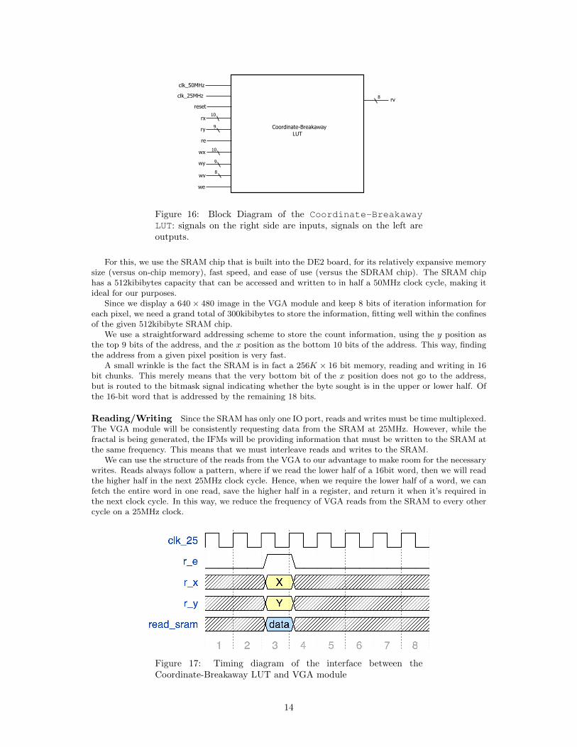
Figure 16: Block Diagram of the Coordinate-BreakawayLUT: signals on the right side are inputs, signals on the left areoutputs.
For this, we use the SRAM chip that is built into the DE2 board, for its relatively expansive memorysize (versus on-chip memory), fast speed, and ease of use (versus the SDRAM chip). The SRAM chiphas a 512kibibytes capacity that can be accessed and written to in half a 50MHz clock cycle, making itideal for our purposes.
Since we display a 640 × 480 image in the VGA module and keep 8 bits of iteration information foreach pixel, we need a grand total of 300kibibytes to store the information, fitting well within the confinesof the given 512kibibyte SRAM chip.
We use a straightforward addressing scheme to store the count information, using the y position asthe top 9 bits of the address, and the x position as the bottom 10 bits of the address. This way, findingthe address from a given pixel position is very fast.
A small wrinkle is the fact the SRAM is in fact a 256K × 16 bit memory, reading and writing in 16bit chunks. This merely means that the very bottom bit of the x position does not go to the address,but is routed to the bitmask signal indicating whether the byte sought is in the upper or lower half. Ofthe 16-bit word that is addressed by the remaining 18 bits.
Reading/Writing Since the SRAM has only one IO port, reads and writes must be time multiplexed.The VGA module will be consistently requesting data from the SRAM at 25MHz. However, while thefractal is being generated, the IFMs will be providing information that must be written to the SRAM atthe same frequency. This means that we must interleave reads and writes to the SRAM.
We can use the structure of the reads from the VGA to our advantage to make room for the necessarywrites. Reads always follow a pattern, where if we read the lower half of a 16bit word, then we will readthe higher half in the next 25MHz clock cycle. Hence, when we require the lower half of a word, we canfetch the entire word in one read, save the higher half in a register, and return it when it’s required inthe next clock cycle. In this way, we reduce the frequency of VGA reads from the SRAM to every othercycle on a 25MHz clock.
Figure 17: Timing diagram of the interface between theCoordinate-Breakaway LUT and VGA module
14
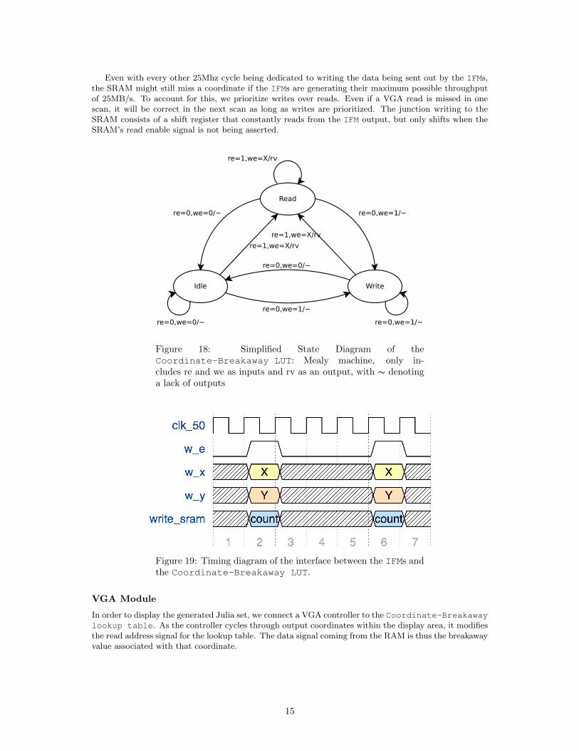
Even with every other 25Mhz cycle being dedicated to writing the data being sent out by the IFMs,the SRAM might still miss a coordinate if the IFMs are generating their maximum possible throughputof 25MB/s. To account for this, we prioritize writes over reads. Even if a VGA read is missed in onescan, it will be correct in the next scan as long as writes are prioritized. The junction writing to theSRAM consists of a shift register that constantly reads from the IFM output, but only shifts when theSRAM’s read enable signal is not being asserted.
Read
WriteIdle
re=0,we=1/~
re=1,we=X/rv
re=0,we=0/~
re=1,we=X/rv
re=1,we=X/rv
re=0,we=0/~
re=0,we=1/~
re=0,we=1/~re=0,we=0/~
Figure 18: Simplified State Diagram of theCoordinate-Breakaway LUT: Mealy machine, only in-cludes re and we as inputs and rv as an output, with ∼ denotinga lack of outputs
Figure 19: Timing diagram of the interface between the IFMs andthe Coordinate-Breakaway LUT.
VGA Module
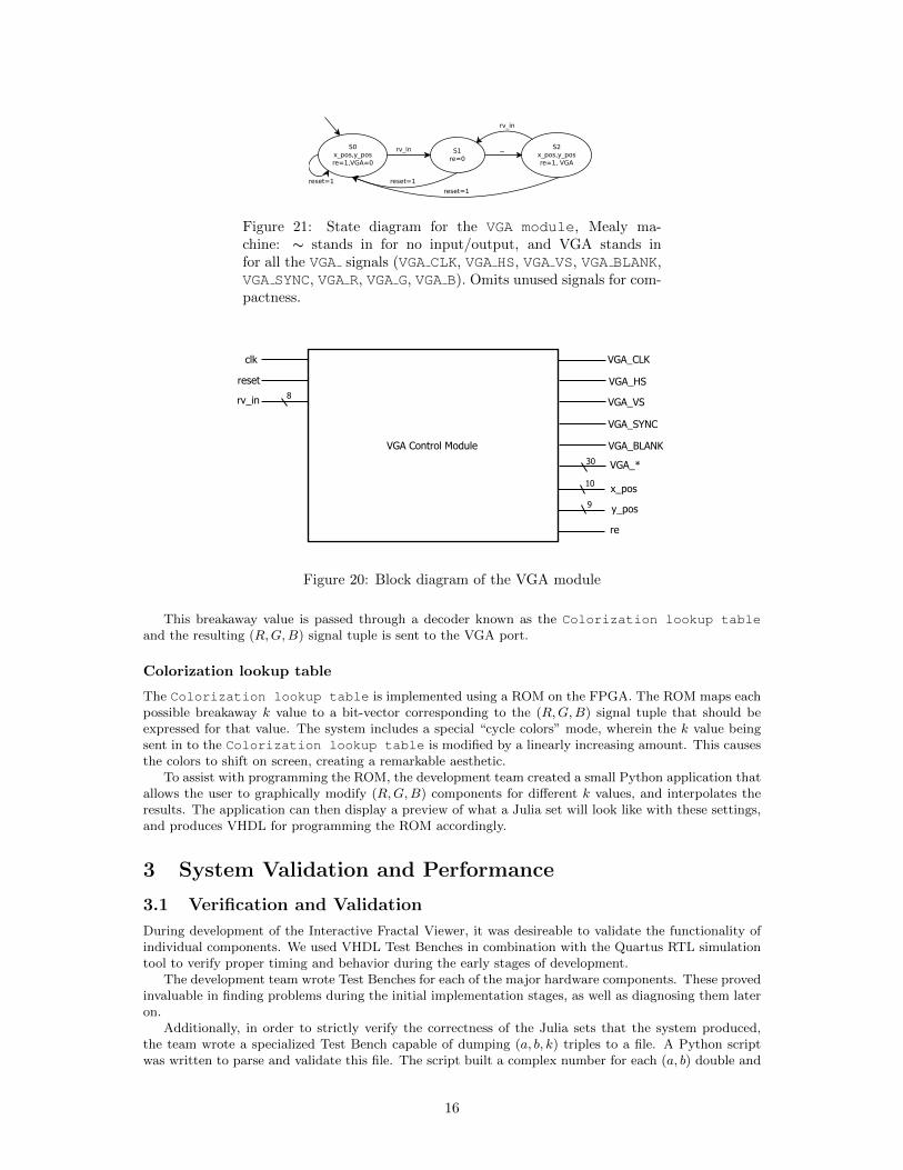
In order to display the generated Julia set, we connect a VGA controller to the Coordinate-Breakawaylookup table. As the controller cycles through output coordinates within the display area, it modifiesthe read address signal for the lookup table. The data signal coming from the RAM is thus the breakawayvalue associated with that coordinate.
15
S0x_pos,y_posre=1,VGA=0
reset=1
S1re=0
S2x_pos,y_posre=1, VGA
rv_in
~rv_in
reset=1
reset=1
Figure 21: State diagram for the VGA module, Mealy ma-chine: ∼ stands in for no input/output, and VGA stands infor all the VGA signals (VGA CLK, VGA HS, VGA VS, VGA BLANK,VGA SYNC, VGA R, VGA G, VGA B). Omits unused signals for com-pactness.
VGA Control Module
VGA_CLK
VGA_HS
VGA_VS
VGA_SYNC
VGA_BLANK
VGA_*
x_pos
y_pos
re
30
10
9
clk
reset
rv_in 8
Figure 20: Block diagram of the VGA module
This breakaway value is passed through a decoder known as the Colorization lookup tableand the resulting (R,G,B) signal tuple is sent to the VGA port.
Colorization lookup table
The Colorization lookup table is implemented using a ROM on the FPGA. The ROM maps eachpossible breakaway k value to a bit-vector corresponding to the (R,G,B) signal tuple that should beexpressed for that value. The system includes a special “cycle colors” mode, wherein the k value beingsent in to the Colorization lookup table is modified by a linearly increasing amount. This causesthe colors to shift on screen, creating a remarkable aesthetic.
To assist with programming the ROM, the development team created a small Python application thatallows the user to graphically modify (R,G,B) components for different k values, and interpolates theresults. The application can then display a preview of what a Julia set will look like with these settings,and produces VHDL for programming the ROM accordingly.
3 System Validation and Performance
3.1 Verification and Validation
During development of the Interactive Fractal Viewer, it was desireable to validate the functionality ofindividual components. We used VHDL Test Benches in combination with the Quartus RTL simulationtool to verify proper timing and behavior during the early stages of development.
The development team wrote Test Benches for each of the major hardware components. These provedinvaluable in finding problems during the initial implementation stages, as well as diagnosing them lateron.
Additionally, in order to strictly verify the correctness of the Julia sets that the system produced,the team wrote a specialized Test Bench capable of dumping (a, b, k) triples to a file. A Python scriptwas written to parse and validate this file. The script built a complex number for each (a, b) double and
16
computed its own breakaway iteration k′ for that value using floating point precision. If the |k−k′| < ε, itmarks the value as a success. Otherwise, it is marked as a failure. The tolerance parameter ε is necessarybecause Julia set iterations represent chaotic systems. Therefore, the minor perturbations caused by thedifference in hardware vs. software computation can cause major changes.
For the Julia set described by a chosen c, and ε = 5, the validation script showed a 98% success rateon the 307200 points tested.
3.2 Performance Analysis
Upper-Bound on Image Generation Time
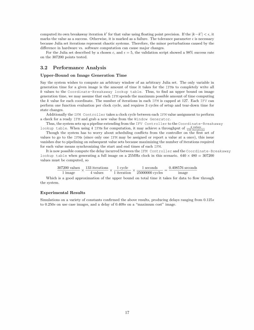
Say the system wishes to compute an arbitrary window of an arbitrary Julia set. The only variable ingeneration time for a given image is the amount of time it takes for the IFMs to completely write allk values to the Coordinate-Breakaway lookup table. Thus, to find an upper bound on imagegeneration time, we may assume that each IFM spends the maximum possible amount of time computingthe k value for each coordinate. The number of iterations in each IFM is capped at 127. Each IFV canperform one function evaluation per clock cycle, and requires 3 cycles of setup and tear-down time forstate changes.
Additionally the IFM Controller takes a clock cycle between each IFM value assignment to performa check for a ready IFM and grab a new value from the Window Generator.
Thus, the system sets up a pipeline extending from the IFV Controller to the Coordinate-Breakawaylookup table. When using 4 IFMs for computation, it may achieve a throughput of 4 values
133 iterations
Though the system has to worry about scheduling conflicts from the controller on the first set ofvalues to go to the IFMs (since only one IFM may be assigned or report a value at a once), this issuevanishes due to pipelining on subsequent value sets because maximizing the number of iterations requiredfor each value means synchronizing the start and end times of each IFM.
It is now possible compute the delay incurred between the IFM Controller and the Coordinate-Breakawaylookup table when generating a full image on a 25MHz clock in this scenario. 640 × 480 = 307200values must be computed, so
307200 values
1 image× 133 iterations
4 values× 1 cycle
1 iteration× 1 seconds
25000000 cycles=
0.408576 seconds
image
Which is a good approximation of the upper bound on total time it takes for data to flow throughthe system.
Experimental Results
Simulations on a variety of constants confirmed the above results, producing delays ranging from 0.125sto 0.250s on use case images, and a delay of 0.409s on a “maximum cost” image.
17
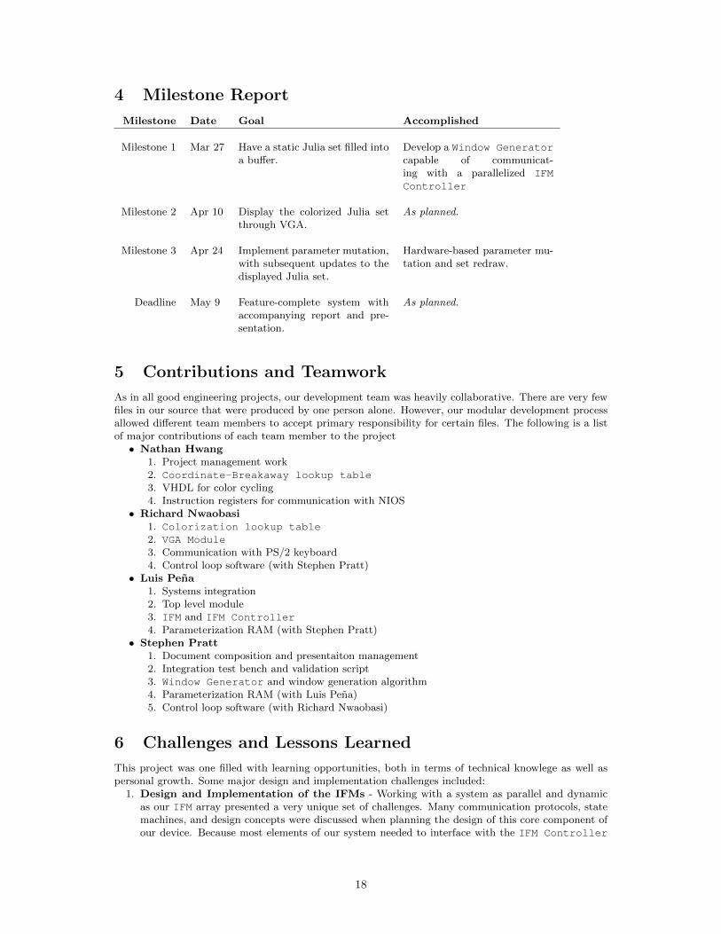
4 Milestone Report
Milestone Date Goal Accomplished
Milestone 1 Mar 27 Have a static Julia set filled intoa buffer.
Develop a Window Generatorcapable of communicat-ing with a parallelized IFMController
Milestone 2 Apr 10 Display the colorized Julia setthrough VGA.
As planned.
Milestone 3 Apr 24 Implement parameter mutation,with subsequent updates to thedisplayed Julia set.
Hardware-based parameter mu-tation and set redraw.
Deadline May 9 Feature-complete system withaccompanying report and pre-sentation.
As planned.
5 Contributions and Teamwork
As in all good engineering projects, our development team was heavily collaborative. There are very fewfiles in our source that were produced by one person alone. However, our modular development processallowed different team members to accept primary responsibility for certain files. The following is a listof major contributions of each team member to the project• Nathan Hwang
1. Project management work2. Coordinate-Breakaway lookup table3. VHDL for color cycling4. Instruction registers for communication with NIOS
• Richard Nwaobasi1. Colorization lookup table2. VGA Module3. Communication with PS/2 keyboard4. Control loop software (with Stephen Pratt)
• Luis Pena1. Systems integration2. Top level module3. IFM and IFM Controller4. Parameterization RAM (with Stephen Pratt)
• Stephen Pratt1. Document composition and presentaiton management2. Integration test bench and validation script3. Window Generator and window generation algorithm4. Parameterization RAM (with Luis Pena)5. Control loop software (with Richard Nwaobasi)
6 Challenges and Lessons Learned
This project was one filled with learning opportunities, both in terms of technical knowlege as well aspersonal growth. Some major design and implementation challenges included:
1. Design and Implementation of the IFMs - Working with a system as parallel and dynamicas our IFM array presented a very unique set of challenges. Many communication protocols, statemachines, and design concepts were discussed when planning the design of this core component ofour device. Because most elements of our system needed to interface with the IFM Controller
18
in some way, successful integration of the component was in many ways a cornerstone acheivementfor our team.
2. Maintaining Timing Discipline - Clocks were consistently an adversary for our team, as manyparts of our system needed to operate at different rates. The NIOS processor and the buses itwrites to necessarily run at 50MHz, while the critical path on our IFMs allowed for only 25MHzfrequencies. The SDRAM clock needed to lag the NIOS to account for setup, charging, and holdtimes, and the VGA clock needed to run at just over 25MHz to meet protocol. We did run intotrouble on many occasions when trying to manage interplay between these components, but thistaught us a lot about the importance of synchronization in Embedded Systems and the nature ofPhase-Locked Loops.
Furthermore, each group member ended up with a few personal takeaways:• Nathan Hwang
1. Between the team and the tools, the team is the greater.• Richard Nwaobasi
1. I would say that while it’s good to enjoy early success, keep in mind that the the road to aproject’s final realization is a long and uneven one. In addition to this, form good relationshipswith your teammates: it makes those late nights that turn into early mornings all the morebearable, and at times even enjoyable and worthwhile.
• Luis Pena1. Modularity is golden. The team divided up the IFV into smaller components to be able to test
their functions easily. This modularity helped so much that the first time we connected thecore components, they all worked.
2. Meeting with the team early on to discuss interfaces and protocols was really useful becausewe did not have to work together all the time to create our individual components.
3. We should have listened more to Dr. Edwards because he knows about many of the issues wefaced. We should have made more use of his office hours, especially because he was our adviserfor the project.
• Stephen Pratt1. Consistent progress is of central importance to the success of a project. A team should always
focus on moving forward at least a little bit, no matter how busy the week. Even the mostmarginal rates of progress are far preferable to the overhead that ends up getting poured intoteardown/setup time if a team decides to focus its efforts elsewhere for even a short period.
2. Implementation challenges are not exam questions. They do not need to be solved alone, oreven successfully on the first go around. It’s far better to experiment and utilize resourcesthat are available than to design a failing solution and pour time into trying to make theimplementation work out.
7 Reflections and Prospective
All things considered, our team is extremely satisfied with the results that we’ve achieved. Developmentwas certainly not without its ups and downs, but we ultimately brought all major project goals to fruition.
Of course, like all good engineers, we can never claim to be completely satisfied with the fruits of ourlabor. The following are a few features that we would like to implement once we have more time to workwith the project:
1. Though window and constant selection are currently software-mutable system parameters, the UIthrough which these parameters are modified does not allow very intuitive control of their values. Aprimary reason for this is that our original system architecture was built with the explicit purposeof drawing fractals on the screen, not anything else. In the future, we would like to let users selecta custom window by modifying a frame on-screen. Explicit, rather than relative specification ofnew seed constants for the Julia set would also be desirable.
2. There exist a few timing glitches that were never completely resolved. Ironing out these glitches isa high priority for future work.
3. It is our professional opinion that the color-cycle mode is totally radical. Having this cycling ratevary with audio input would turn our Interactive Fractal Viewer into a spectacular music visualizer.
19
A Source Code
A.1 VHDL
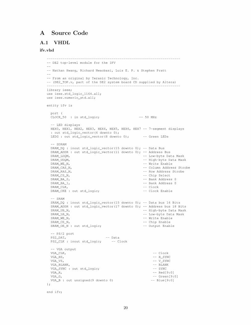
ifv.vhd
---------------------------------------------------------------------- DE2 top-level module for the IFV---- Nathan Hwang, Richard Nwaobasi, Luis E. P. & Stephen Pratt---- From an original by Terasic Technology, Inc.-- (DE2_TOP.v, part of the DE2 system board CD supplied by Altera)--------------------------------------------------------------------library ieee;use ieee.std_logic_1164.all;use ieee.numeric_std.all;
entity ifv is
port (CLOCK_50 : in std_logic; -- 50 MHz
-- LED displaysHEX0, HEX1, HEX2, HEX3, HEX4, HEX5, HEX6, HEX7 -- 7-segment displays: out std_logic_vector(6 downto 0);LEDG : out std_logic_vector(8 downto 0); -- Green LEDs
-- SDRAMDRAM_DQ : inout std_logic_vector(15 downto 0); -- Data BusDRAM_ADDR : out std_logic_vector(11 downto 0); -- Address BusDRAM_LDQM, -- Low-byte Data MaskDRAM_UDQM, -- High-byte Data MaskDRAM_WE_N, -- Write EnableDRAM_CAS_N, -- Column Address StrobeDRAM_RAS_N, -- Row Address StrobeDRAM_CS_N, -- Chip SelectDRAM_BA_0, -- Bank Address 0DRAM_BA_1, -- Bank Address 0DRAM_CLK, -- ClockDRAM_CKE : out std_logic; -- Clock Enable
-- SRAMSRAM_DQ : inout std_logic_vector(15 downto 0); -- Data bus 16 BitsSRAM_ADDR : out std_logic_vector(17 downto 0); -- Address bus 18 BitsSRAM_UB_N, -- High-byte Data MaskSRAM_LB_N, -- Low-byte Data MaskSRAM_WE_N, -- Write EnableSRAM_CE_N, -- Chip EnableSRAM_OE_N : out std_logic; -- Output Enable
-- PS/2 portPS2_DAT, -- DataPS2_CLK : inout std_logic; -- Clock
-- VGA outputVGA_CLK, -- ClockVGA_HS, -- H_SYNCVGA_VS, -- V_SYNCVGA_BLANK, -- BLANKVGA_SYNC : out std_logic; -- SYNCVGA_R, -- Red[9:0]VGA_G, -- Green[9:0]VGA_B : out unsigned(9 downto 0) -- Blue[9:0]
);
end ifv;
20
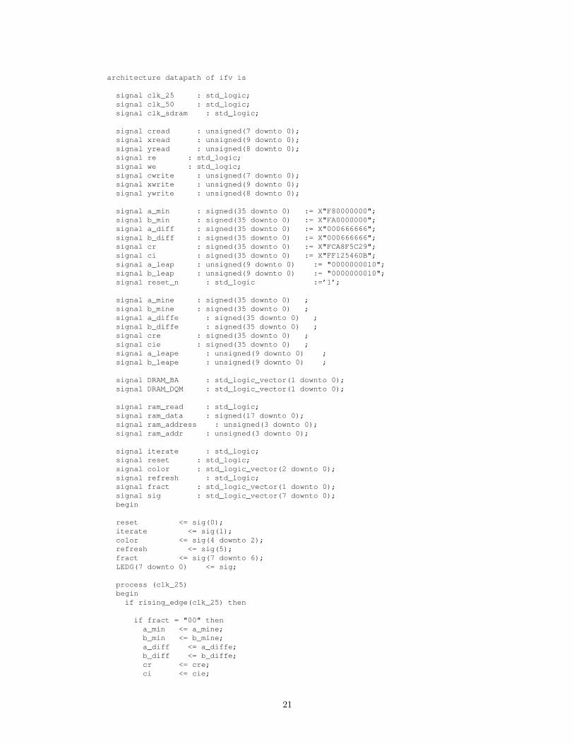
architecture datapath of ifv is
signal clk_25 : std_logic;signal clk_50 : std_logic;signal clk_sdram : std_logic;
signal cread : unsigned(7 downto 0);signal xread : unsigned(9 downto 0);signal yread : unsigned(8 downto 0);signal re : std_logic;signal we : std_logic;signal cwrite : unsigned(7 downto 0);signal xwrite : unsigned(9 downto 0);signal ywrite : unsigned(8 downto 0);
signal a_min : signed(35 downto 0) := X"F80000000";signal b_min : signed(35 downto 0) := X"FA0000000";signal a_diff : signed(35 downto 0) := X"000666666";signal b_diff : signed(35 downto 0) := X"000666666";signal cr : signed(35 downto 0) := X"FCA8F5C29";signal ci : signed(35 downto 0) := X"FF125460B";signal a_leap : unsigned(9 downto 0) := "0000000010";signal b_leap : unsigned(9 downto 0) := "0000000010";signal reset_n : std_logic :=’1’;
signal a_mine : signed(35 downto 0) ;signal b_mine : signed(35 downto 0) ;signal a_diffe : signed(35 downto 0) ;signal b_diffe : signed(35 downto 0) ;signal cre : signed(35 downto 0) ;signal cie : signed(35 downto 0) ;signal a_leape : unsigned(9 downto 0) ;signal b_leape : unsigned(9 downto 0) ;
signal DRAM_BA : std_logic_vector(1 downto 0);signal DRAM_DQM : std_logic_vector(1 downto 0);
signal ram_read : std_logic;signal ram_data : signed(17 downto 0);signal ram_address : unsigned(3 downto 0);signal ram_addr : unsigned(3 downto 0);
signal iterate : std_logic;signal reset : std_logic;signal color : std_logic_vector(2 downto 0);signal refresh : std_logic;signal fract : std_logic_vector(1 downto 0);signal sig : std_logic_vector(7 downto 0);begin
reset <= sig(0);iterate <= sig(1);color <= sig(4 downto 2);refresh <= sig(5);fract <= sig(7 downto 6);LEDG(7 downto 0) <= sig;
process (clk_25)begin
if rising_edge(clk_25) then
if fract = "00" thena_min <= a_mine;b_min <= b_mine;a_diff <= a_diffe;b_diff <= b_diffe;cr <= cre;ci <= cie;
21
a_leap <= a_leape;b_leap <= b_leape;
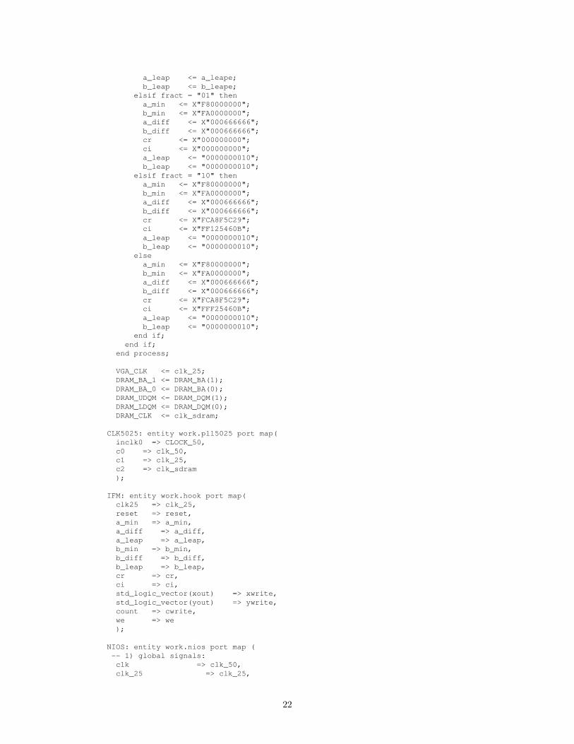
elsif fract = "01" thena_min <= X"F80000000";b_min <= X"FA0000000";a_diff <= X"000666666";b_diff <= X"000666666";cr <= X"000000000";ci <= X"000000000";a_leap <= "0000000010";b_leap <= "0000000010";
elsif fract = "10" thena_min <= X"F80000000";b_min <= X"FA0000000";a_diff <= X"000666666";b_diff <= X"000666666";cr <= X"FCA8F5C29";ci <= X"FF125460B";a_leap <= "0000000010";b_leap <= "0000000010";
elsea_min <= X"F80000000";b_min <= X"FA0000000";a_diff <= X"000666666";b_diff <= X"000666666";cr <= X"FCA8F5C29";ci <= X"FFF25460B";a_leap <= "0000000010";b_leap <= "0000000010";
end if;end if;
end process;
VGA_CLK <= clk_25;DRAM_BA_1 <= DRAM_BA(1);DRAM_BA_0 <= DRAM_BA(0);DRAM_UDQM <= DRAM_DQM(1);DRAM_LDQM <= DRAM_DQM(0);DRAM_CLK <= clk_sdram;
CLK5025: entity work.pll5025 port map(inclk0 => CLOCK_50,c0 => clk_50,c1 => clk_25,c2 => clk_sdram);
IFM: entity work.hook port map(clk25 => clk_25,reset => reset,a_min => a_min,a_diff => a_diff,a_leap => a_leap,b_min => b_min,b_diff => b_diff,b_leap => b_leap,cr => cr,ci => ci,std_logic_vector(xout) => xwrite,std_logic_vector(yout) => ywrite,count => cwrite,we => we);
NIOS: entity work.nios port map (-- 1) global signals:clk => clk_50,clk_25 => clk_25,
22
reset_n => ’1’,
PS2_CLK_to_and_from_the_ps2_0 => PS2_CLK,PS2_DAT_to_and_from_the_ps2_0 => PS2_DAT,irq_from_the_ps2_0 => LEDG(8),
-- the_ramaddressout_to_the_ram => std_logic_vector(ram_address),read_to_the_ram => ram_read,std_logic_vector(readdata_from_the_ram) => ram_data,std_logic_vector(readaddr_from_the_ram) => ram_addr,
-- the sram signalread_addr_to_the_ram_signal => ’0’,read_data_from_the_ram_signal => sig,
-- the_sdramzs_addr_from_the_sdram => DRAM_ADDR,zs_ba_from_the_sdram => DRAM_BA,zs_cas_n_from_the_sdram => DRAM_CAS_N,zs_cke_from_the_sdram => DRAM_CKE,zs_cs_n_from_the_sdram => DRAM_CS_N,zs_dq_to_and_from_the_sdram => DRAM_DQ,zs_dqm_from_the_sdram => DRAM_DQM,zs_ras_n_from_the_sdram => DRAM_RAS_N,zs_we_n_from_the_sdram => DRAM_WE_N);
RMR: entity work.rammer port map(clk => clk_25,compute => refresh,read => ram_read,addressout => ram_address,addressin => ram_addr,readdata => ram_data,amin => a_mine,bmin => b_mine,adiff => a_diffe,bdiff => b_diffe,aleap => a_leape,bleap => b_leape,cro => cre,cio => cie);
VGA: entity work.vga_mod port map (clk => clk_25,reset => ’0’,switch => color,count => cread,--EXTERNAL SIGNALSVGA_HS => VGA_HS,VGA_VS => VGA_VS,VGA_BLANK => VGA_BLANK,VGA_SYNC => VGA_SYNC,VGA_R => VGA_R,VGA_G => VGA_G,VGA_B => VGA_B,xout => xread,--EXTERNAL SIGNALSyout => yread,--EXTERNAL SIGNALSre => re,--EXTERNAL SIGNALSce => iterate);
SRAM: entity work.sram port map(sram_data => SRAM_DQ,sram_addr => SRAM_ADDR,sram_ub_n => SRAM_UB_N,sram_lb_n => SRAM_LB_N,
23
sram_we_n => SRAM_WE_N,sram_ce_n => SRAM_CE_N,sram_oe_n => SRAM_OE_N,rx => std_logic_vector(xread),ry => std_logic_vector(yread),wx => std_logic_vector(xwrite),wy => std_logic_vector(ywrite),std_logic_vector(rv) => cread,wv => std_logic_vector(cwrite),re => re,we => we);
HEX7 <= "1100001"; -- JHEX6 <= "1000001"; -- UHEX5 <= "1000111"; -- LHEX4 <= "1111001"; -- IHEX3 <= "0001000"; -- AHEX2 <= "0010010"; -- SHEX1 <= "0000110"; -- EHEX0 <= "0000111"; -- t
end datapath;
ramcon.vhd
-----------------------------------------------------------------------ramcon----This is the entity holding all four IFMs. This is where all the--wiring and the IFM coordination takes place.----Author: Luis E. P.---------------------------------------------------------------------library ieee;use ieee.std_logic_1164.all;use ieee.numeric_std.all;
entity ramcon isport(clk : in std_logic;reset_n : in std_logic;read : in std_logic;write : in std_logic;chipselect : in std_logic;address : in unsigned(3 downto 0);addressout : in unsigned(3 downto 0);
readaddr : out unsigned(3 downto 0);readdata : out unsigned(17 downto 0);writedata : in unsigned(31 downto 0));
end ramcon;
architecture ramarch of ramcon is
type ram_type is array(15 downto 0) of unsigned(17 downto 0);signal RAM : ram_type;begin
process(clk)begin
if rising_edge(clk) thenreadaddr <= addressout;readdata <= RAM(to_integer(addressout));if chipselect = ’1’ thenif write = ’1’ thenRAM(to_integer(address)) <= writedata(17 downto 0);
24
end if;end if;
end if;end process;
end ramarch;
rammer.vhd
window gen.vhd
-----------------------------------------------------------------------window_gen.vhd----A device used to generate (a, b) values for each pixel on the--screen under the given window parameters.----Author: Stephen Pratt---------------------------------------------------------------------
library ieee;use ieee.std_logic_1164.all;use ieee.numeric_std.all;
entity window_gen is
port (clk : in std_logic;
next_val : in std_logic;reset : in std_logic;
a_min : in signed(35 downto 0);a_diff : in signed(35 downto 0);a_leap : in unsigned(9 downto 0);b_min : in signed(35 downto 0);b_diff : in signed(35 downto 0);b_leap : in unsigned(9 downto 0);
a_out : out std_logic_vector(35 downto 0);b_out : out std_logic_vector(35 downto 0);x_out : out std_logic_vector(9 downto 0);y_out : out std_logic_vector(9 downto 0);ready : out std_logic);
end window_gen;
architecture wg of window_gen is
constant HACTIVE : integer := 640-1;constant VACTIVE : integer := 480-1;
signal x_max : unsigned(9 downto 0) := to_unsigned(HACTIVE, 10);signal y_max : unsigned(9 downto 0) := to_unsigned(VACTIVE, 10);
signal a_at_max : std_logic;signal b_at_max : std_logic;signal both_max : std_logic;
signal a_ready : std_logic;signal b_ready : std_logic;
signal b_next : std_logic;signal a_reset : std_logic;
signal y_out_mirror : std_logic_vector(9 downto 0);
25
begin
b_next <= next_val and a_at_max;
both_max <= a_at_max and b_at_max;
a_reset <= reset or (b_next and not both_max);y_out <= std_logic_vector(y_max - unsigned(y_out_mirror));
ready <= a_ready and b_ready;
--Module is composed of two diff_counters, one for each--screen dimension.a_counter: entity work.diff_counter port map (
clk => clk,next_val => next_val,reset => a_reset,
v_min => a_min,v_diff => a_diff,v_leap => a_leap,max_itr => x_max,
v_out => a_out,c_out => x_out,at_max => a_at_max,ready => a_ready
);
b_counter: entity work.diff_counter port map (clk => clk,next_val => b_next,reset => reset,
v_min => b_min,v_diff => b_diff,v_leap => b_leap,max_itr => y_max,
v_out => b_out,c_out => y_out_mirror,at_max => b_at_max,ready => b_ready
);
end wg;
diff counter.vhd
-----------------------------------------------------------------------diff_counter.vhd----A device that increments a value by some differential, adjusting--the sum as necessary to assure convergence to a maximum value.----Author: Stephen Pratt---------------------------------------------------------------------
library ieee;use ieee.std_logic_1164.all;use ieee.numeric_std.all;
entity diff_counter is
port (
26
clk : in std_logic;next_val : in std_logic;reset : in std_logic;
v_min : in signed(35 downto 0);v_diff : in signed(35 downto 0);v_leap : in unsigned(9 downto 0);max_itr : in unsigned(9 downto 0);
v_out : out std_logic_vector(35 downto 0);c_out : out std_logic_vector(9 downto 0);at_max : out std_logic;ready : out std_logic
);
end diff_counter;
architecture dc of diff_counter is
signal itr_count : unsigned (9 downto 0);signal leap : std_logic;signal v_next : signed(35 downto 0);signal c_next : unsigned(9 downto 0);signal itr_next : unsigned(9 downto 0);signal v_curr : signed(35 downto 0);signal c_curr : unsigned(9 downto 0);
signal v_sum : signed (35 downto 0);signal ready_sig : std_logic := ’0’;
begin
c_out <= std_logic_vector(c_curr);v_out <= std_logic_vector(v_curr);ready <= ready_sig;
process(clk)
begin
if rising_edge(clk) then
c_next <= c_curr+1;v_next <= v_curr + v_diff;
itr_next <= itr_count+1; --itr_next is leap counter
--make adjustment on leap countif leap = ’1’ thenv_next <= v_curr + v_diff + 1;itr_next <= (others=>’0’); --reset leap counter to zero
end if;
leap <= ’0’;
--if we complete a leap interval, we should leap next cycleif itr_next = v_leap thenleap <= ’1’;
end if;
itr_count <= itr_count;
--Reset operation - tra---------------------------------------------------------------------
--vga_mod.vhd----This unit connects the VGA raster and the Color_LUT.--
27
--Author: Richard Nwaobasi---------------------------------------------------------------------
library ieee;use ieee.std_logic_1164.all;use ieee.numeric_std.all;
entity vga_mod isport(
clk, reset : in std_logic;count : in unsigned(7 downto 0);switch : in std_logic_vector(2 downto 0);VGA_HS, -- H_SYNCVGA_VS, -- V_SYNCVGA_BLANK, -- BLANKVGA_SYNC : out std_logic; -- SYNCVGA_R, -- Red[9:0]VGA_G, -- Green[9:0]VGA_B : out unsigned(9 downto 0); -- Blue[9:0]xout : out unsigned(9 downto 0);yout : out unsigned(8 downto 0);re : out std_logic;ce : in std_logic
);end vga_mod;
architecture imp of vga_mod is
component vgaport (reset : in std_logic;clk : in std_logic; -- Should be 25.125 MHzVGA_RGB : in unsigned(29 downto 0);VGA_HS, -- H_SYNCVGA_VS, -- V_SYNCVGA_BLANK, -- BLANKVGA_SYNC : out std_logic; -- SYNCVGA_R, -- Red[9:0]VGA_G, -- Green[9:0]VGA_B : out unsigned(9 downto 0); -- Blue[9:0]x_pos : out unsigned(9 downto 0);y_pos : out unsigned(8 downto 0);re : out std_logic -- Read Enable);
end component;
component Color_LUTport(count : in unsigned(7 downto 0);switch : in std_logic_vector(2 downto 0);VGA_RGB : out unsigned(29 downto 0));
end component;
signal VGA_RGB : unsigned(29 downto 0);
signal cycle : unsigned(7 downto 0) := (others => ’0’);signal spacer : unsigned(19 downto 0) := (others => ’0’);
begin
G : vga port map (reset => reset,clk => clk, -- Should be 25.125 MHzVGA_RGB => VGA_RGB,VGA_HS => VGA_HS,VGA_VS => VGA_VS,VGA_BLANK => VGA_BLANK,VGA_SYNC => VGA_SYNC,VGA_R => VGA_R,
28
VGA_G => VGA_G,VGA_B => VGA_B,x_pos => xout,y_pos => yout,re => re);
A : Color_LUT port map(count => count + cycle,switch => switch,VGA_RGB => VGA_RGB);
process(clk)begin
if rising_edge(clk) thenif reset = ’1’ thenspacer <= (others => ’0’);cycle <= (others => ’0’);
end if;if ce = ’1’ thenspacer <= spacer + 1;if spacer = 0 thencycle <= cycle + 1;
end if;end if;
end if;end process;
end imp;nsition to start stateif reset = ’1’ thenv_curr <= v_min;c_curr <= (others=>’0’);itr_count <= (others=>’0’);at_max <= ’0’;ready_sig <= ’1’;
--Maximum iteration reached - transition to max stateelsif c_curr = max_itr thenat_max <= ’1’;
--Next value requestedelsif next_val = ’1’ thenc_curr <= c_next;v_curr <= v_next;itr_count <= itr_next;
end if;
end if;end process;
end dc;
hook.vhd
-----------------------------------------------------------------------hook.vhd----This is the place where the IFMs and their controller connect with--the window generator that feeds the IFMs.----Author: Luis E. P.---------------------------------------------------------------------library ieee;use ieee.std_logic_1164.all;use ieee.numeric_std.all;
entity hook isport(
29
clk25 : in std_logic;reset : in std_logic; -- Cleara_min : in signed(35 downto 0);a_diff : in signed(35 downto 0);a_leap : in unsigned(9 downto 0);b_min : in signed(35 downto 0);b_diff : in signed(35 downto 0);b_leap : in unsigned(9 downto 0);cr : in signed(35 downto 0);ci : in signed(35 downto 0);xout : out std_logic_vector(9 downto 0);yout : out std_logic_vector(8 downto 0);count : out unsigned (7 downto 0);we : out std_logic);
end hook;
architecture first of hook issignal nxt : std_logic;signal ai : std_logic_vector(35 downto 0);signal bi : std_logic_vector(35 downto 0);signal x : std_logic_vector(9 downto 0);signal yi : std_logic_vector(8 downto 0);signal yo : std_logic_vector(9 downto 0);signal data : std_logic;
beginyi <= yo(8 downto 0);
gen: entity work.window_gen port map(clk => clk25,next_val => nxt,reset => reset,a_min => a_min,a_diff => a_diff,a_leap => a_leap,b_min => b_min,b_diff => b_diff,b_leap => b_leap,a_out => ai,b_out => bi,x_out => x,y_out => yo,ready => data
);
ifm: entity work.ifmunitd port map(clk25 => clk25,reset => reset,data => data,xin => x,yin => yi,ain => ai,bin => bi,cr => cr,ci => ci,xout => xout,yout => yout,count => count,full => nxt,we => we
);
end first;\end{Huge}
\subsubsection{ifmd.vhd} %Luis
30
\begin{lstlisting}-----------------------------------------------------------------------ifmd.vhd----This is the iterating unit. This unit, given a complex number and a--complex constant, calculates the number of iterations until breakaway--or whether or not the coordinate is out of bounds----Author: Luis E. P.---------------------------------------------------------------------library ieee;use ieee.std_logic_1164.all;use ieee.numeric_std.all;
entity ifmd is
port(
clock : in std_logic; -- Global clockclr : in std_logic; -- Clearcompute : in std_logic; -- Controls when IFM starts iterating.
Set high to start iterationsxin : in std_logic_vector(9 downto 0); -- The x coordinate inputyin : in std_logic_vector(8 downto 0); -- The y coordinate inputain : in std_logic_vector(35 downto 0); -- Real part of inputbin : in std_logic_vector(35 downto 0); -- Imaginary part of inputcr : in signed(35 downto 0); -- Real part of constantci : in signed(35 downto 0); -- Imaginary part of constantxout : out std_logic_vector(9 downto 0); -- The x coordinate outputyout : out std_logic_vector(8 downto 0); -- The y coordinate outputcount : out unsigned(7 downto 0); -- Iteration countdon : out std_logic; -- Becomes high when the iterator is done
iteratingready : out std_logic -- Becomes high when the IFM is ready for
new data
);
end ifmd;
architecture first of ifmd issignal proda : std_logic_vector(71 downto 0);signal prodb : std_logic_vector(71 downto 0);signal prodc : std_logic_vector(71 downto 0);signal x : std_logic_vector(9 downto 0); -- The x coordinatesignal y : std_logic_vector(8 downto 0); -- The y coordinatesignal a : std_logic_vector(35 downto 0);signal b : std_logic_vector(35 downto 0);signal spa : signed(35 downto 0); -- proda "trimmed" to 36 bitssignal spb : signed(35 downto 0); -- prodb "trimmed" to 36 bitssignal spc : signed(35 downto 0); -- prodc "trimmed" to 36 bitssignal sumr : signed(35 downto 0); -- Difference of the squaressignal sumi : signed(35 downto 0); -- Product multiplied by twosignal newr : signed(35 downto 0); -- Newly computed Re{z}
before flip flopsignal newi : signed(35 downto 0); -- Newly computed Im{z}
before flip flopsignal oldr : std_logic_vector(35 downto 0); -- Re{z} after flip flopsignal oldi : std_logic_vector(35 downto 0); -- Im{z} after flip flopsignal mag2 : signed(35 downto 0); -- Magnitude squared of
current a & bsignal counter : unsigned(7 downto 0) := (others => ’0’); -- Counter for
iterationssignal done : std_logic := ’0’; -- Indicates if IFM is done
iterating
31
begin
spa <= signed(proda(65 downto 30)); --Change range depending on radix.Assuming 6-bit & 30-bit
spb <= signed(prodb(65 downto 30));spc <= signed(prodc(65 downto 30));
sumr <= spa - spb;sumi <= spc + spc;mag2 <= spa + spb;
newr <= sumr + cr; -- Add Re{c}newi <= sumi + ci; -- Add Im{c}
count <= counter;don <= done;ready <= clr nor compute;xout <= x;yout <= y;
-- aout <= a;-- bout <= b;
process(clock)beginif rising_edge(clock) then
if clr = ’1’ thendone <= ’0’;counter <= (others => ’0’);oldr <= (others => ’0’);oldi <= (others => ’0’);x <= (others => ’0’);y <= (others => ’0’);a <= (others => ’0’);b <= (others => ’0’);
elsif counter = "01111111" or mag2 > "000010000000000000000000000000000000"then -- More than 127 iterations or more than 4 mag squared?
done <= ’1’;elsif compute = ’1’ then -- Are we iterating?oldr <= std_logic_vector(newr); -- Store Re{z}oldi <= std_logic_vector(newi); -- Store Im{z}if counter = "00000000" thencounter <= "00000001";
elsecounter <= counter + 1;
end if;x <= x;y <= y;a <= a;b <= b;
elseoldr <= ain; -- Get value from outsieoldi <= bin; -- Get value from outsidex <= xin;y <= yin;a <= ain;b <= bin;
end if;end if;end process;
multa: entity work.sqr2 port map(dataa => oldr,result => proda
);
multb: entity work.sqr2 port map(dataa => oldi,result => prodb
32
);
multc: entity work.mult2 port map(dataa => oldr,datab => oldi,result => prodc
);
end first;
ifmunitd.vhd
-----------------------------------------------------------------------ifmunitd.vhd----This is the entity holding all four IFMs. This is where all the--wiring and the IFM coordination takes place.----Author: Luis E. P.---------------------------------------------------------------------library ieee;use ieee.std_logic_1164.all;use ieee.numeric_std.all;
entity ifmunitd isport(clk25 : in std_logic;reset : in std_logic;data : in std_logic; --Asserted high when data is ready to be
readxin : in std_logic_vector(9 downto 0);yin : in std_logic_vector(8 downto 0);ain : in std_logic_vector(35 downto 0);bin : in std_logic_vector(35 downto 0);cr : in signed(35 downto 0);ci : in signed(35 downto 0);xout : out std_logic_vector(9 downto 0);yout : out std_logic_vector(8 downto 0);count : out unsigned(7 downto 0); --Data to be written in memoryfull : out std_logic;we : out std_logic -- Write enable);
end ifmunitd;
architecture qq of ifmunitd is
--Input busestype inRecord is record
d : std_logic;a : std_logic_vector(35 downto 0);b : std_logic_vector(35 downto 0);cr : signed(35 downto 0);ci : signed(35 downto 0);x : std_logic_vector(9 downto 0);y : std_logic_vector(8 downto 0);
end record;type inArray is array (0 to 1) of inRecord;
--Buses connecting to the IFMstype bxifm is array (0 to 3) of std_logic_vector(9 downto 0);type byifm is array (0 to 3) of std_logic_vector(8 downto 0);type baifm is array (0 to 3) of std_logic_vector(35 downto 0);type bbifm is array (0 to 3) of std_logic_vector(35 downto 0);type bcount is array (0 to 3) of unsigned(7 downto 0);type bdon is array (0 to 3) of std_logic;type bread is array (0 to 3) of std_logic;type bclr is array (0 to 3) of std_logic;
33
type bcompute is array (0 to 3) of std_logic;
--Buses for the output buffer Currently one output stagetype owb is array (0 to 0) of std_logic;type ocb is array (0 to 0) of unsigned(7 downto 0);type oxb is array (0 to 0) of std_logic_vector(9 downto 0);type oyb is array (0 to 0) of std_logic_vector(8 downto 0);type oab is array (0 to 0) of std_logic_vector(35 downto 0);type obb is array (0 to 0) of std_logic_vector(35 downto 0);
signal ia : inArray;
signal bx : bxifm;signal by : byifm;signal ba : baifm;signal bb : bbifm;signal bc : bcount;signal bdone : bdon;signal bready : bread;signal bclear : bclr;signal bcomp : bcompute;
signal ow : owb;signal oc : ocb;signal ox : oxb;signal oy : oyb;
beginfull <= not ia(1).d;xout <= ox(0);yout <= oy(0);we <= ow(0);count <= oc(0);
process(clk25)beginif rising_edge(clk25) thenif reset = ’1’ then
init1: for m in 0 to 0 loopow(m) <= ’0’;oc(m) <= (others => ’0’);
end loop init1;else
if bdone(0) = ’1’ thenox(0) <= bx(0);oy(0) <= by(0);oc(0) <= bc(0);ow(0) <= ’1’;
elsif bdone(1) = ’1’ thenox(0) <= bx(1);oy(0) <= by(1);oc(0) <= bc(1);ow(0) <= ’1’;
elsif bdone(2) = ’1’ thenox(0) <= bx(2);oy(0) <= by(2);oc(0) <= bc(2);ow(0) <= ’1’;
elsif bdone(3) = ’1’ thenox(0) <= bx(3);oy(0) <= by(3);oc(0) <= bc(3);ow(0) <= ’1’;
elseox(0) <= (others => ’0’);oy(0) <= (others => ’0’);oc(0) <= (others => ’0’);ow(0) <= ’0’;
34
end if;end if;end if;end process;
process(clk25)beginif rising_edge(clk25) then
if reset = ’1’ then
init0: for idx in 0 to 1 loopia(idx).d <= ’0’;ia(idx).a <= (others => ’0’);ia(idx).b <= (others => ’0’);ia(idx).cr <= (others => ’0’);ia(idx).ci <= (others => ’0’);ia(idx).x <= (others => ’0’);ia(idx).y <= (others => ’0’);end loop init0;
init2: for n in 0 to 3 loopbclear(n) <= ’1’;bcomp(n) <= ’0’;end loop init2;
else
-- INPUT BUFFER:if ia(1).d = ’0’ thenif data = ’1’ thenia(1).a <= ain;ia(1).b <= bin;ia(1).cr <= cr;ia(1).ci <= ci;ia(1).x <= xin;ia(1).y <= yin;ia(1).d <= ’1’;elseia(1).d <= ’0’;end if;end if;
if ia(0).d = ’0’ thenif ia(1).d = ’1’ thenia(0).a <= ia(1).a;ia(0).b <= ia(1).b;ia(0).cr <= ia(1).cr;ia(0).ci <= ia(1).ci;ia(0).x <= ia(1).x;ia(0).y <= ia(1).y;ia(0).d <= ia(1).d;ia(1).d <= ’0’;elseia(0).d <= ’0’;end if;end if;
-- END INPUT BUFFER
-- Ready available IFMsclear: for idx in 0 to 3 loop
if bclear(idx) = ’1’ then -- Availability checkbclear(idx) <= ’0’;
end if; -- End availability checkend loop clear;
-- End readying available IFMs
-- Feed ready IFMsif ia(0).d = ’1’ then -- Data validation
35
if bready(0) = ’1’ then -- Ready checkbcomp(0) <= ’1’;ia(0).d <= ’0’;
elsif bready(1) = ’1’ thenbcomp(1) <= ’1’;ia(0).d <= ’0’;
elsif bready(2) = ’1’ thenbcomp(2) <= ’1’;ia(0).d <= ’0’;
elsif bready(3) = ’1’ thenbcomp(3) <= ’1’;ia(0).d <= ’0’;
end if; -- End ready checkend if; -- End data validation
-- End feeding ready IFMs
-- Check done IFMsif bdone(0) = ’1’ then
bclear(0) <= ’1’;bcomp(0) <= ’0’;
elsif bdone(1) = ’1’ thenbclear(1) <= ’1’;bcomp(1) <= ’0’;
elsif bdone(2) = ’1’ thenbclear(2) <= ’1’;bcomp(2) <= ’0’;
elsif bdone(3) = ’1’ thenbclear(3) <= ’1’;bcomp(3) <= ’0’;
end if;-- End checking for done IFMs
end if; -- reset = 1end if; -- rising edgeend process;
g1: for I in 0 to 3 generateifm: entity work.ifmd port map(clock => clk25,clr => bclear(I),compute => bcomp(I),xin => ia(0).x,yin => ia(0).y,ain => ia(0).a,bin => ia(0).b,cr => ia(0).cr,ci => ia(0).ci,xout => bx(I),yout => by(I),count => bc(I),don => bdone(I),ready => bready(I));
end generate;
end qq;
sram.vhd
-----------------------------------------------------------------------sram.vhd----This module is an asynchronous SRAM. This is where the computed--values for each pixel are stored----Author: Nathan Hwang---------------------------------------------------------------------
36
library ieee;use ieee.std_logic_1164.all;use ieee.numeric_std.all;
-- this module expects to bridge from 50Mhz writes to 25MHz readsentity sram is
port(-- SRAM_DQ, 16 bit datasram_data : inout std_logic_vector(15 downto 0);-- SRAM_ADDR, 18 bit address space (256k)sram_addr : out std_logic_vector(17 downto 0);-- SRAM_UB_N, *LB_N, upper and lower byte maskssram_ub_n,sram_lb_n,-- SRAM_WE_N, write enablesram_we_n,-- SRAM_CE_N, chip enable (power up chip)sram_ce_n,-- SRAM_OE_N, output enable (when reading)sram_oe_n : out std_logic;
-- 640<1024 (10 bits)rx : in std_logic_vector(9 downto 0);-- 480<512 (9 bits)ry : in std_logic_vector(8 downto 0);-- same, but for writingwx : in std_logic_vector(9 downto 0);wy : in std_logic_vector(8 downto 0);-- read/write values (8 bits)rv : out std_logic_vector(7 downto 0);wv : in std_logic_vector(7 downto 0);-- read/write controls-- reading takes precedencere : in std_logic;we : in std_logic
);end sram;
architecture sram_arch of sram issignal addr : std_logic_vector(17 downto 0);-- temp addr signalssignal raddr : std_logic_vector(18 downto 0);signal waddr : std_logic_vector(18 downto 0);
-- "really" signalssignal rre : std_logic;signal rwe : std_logic;
-- byte mask, due to 16bit words in SRAMsignal mask : std_logic_vector(1 downto 0);
-- write buffersignal we_buffer : std_logic;signal wv_buffer : std_logic_vector(7 downto 0);signal waddr_buffer : std_logic_vector(18 downto 0);signal wdup : std_logic := ’0’;
begin-- determine whether we really need to read from the SRAMrre <= re when not rwe=’1’ else ’0’;-- determine if we should really write to the SRAM-- rwe <= (we and (not wdup)); -- don’t know why, but this is not better--rwe <= we and not wdup;rwe <= we;
-- generate the addressraddr <= ry(8 downto 0) & rx(9 downto 0);-- for the waddr
37
waddr <= wy(8 downto 0) & wx(9 downto 0);addr <= waddr(18 downto 1) when rwe=’1’ else raddr(18 downto 1);
-- find out if we need to mask either bytemask <= "01" when rwe=’1’ and waddr(0)=’0’ else
"10" when rwe=’1’ and waddr(0)=’1’ else"11" when rre=’1’ else -- always read both bytes"00"; -- don’t read anything by default
-- sram outputssram_addr <= addr;-- going to have to redo this part, migth have to use both bytessram_ub_n <= not mask(1);sram_lb_n <= not mask(0);-- only enable write enable when, well, writingsram_we_n <= not rwe;-- only enable the output when readingsram_oe_n <= not rre;-- always power up the chipsram_ce_n <= ’0’;
-- try to generate the right datasram_data <= wv & "00000000" when (waddr(0)=’1’ and rwe=’1’) else
"00000000" & wv when (waddr(0)=’0’ and rwe=’1’) else(others => ’Z’);
-- module outputsrv <= sram_data(7 downto 0) when rre=’1’ and raddr(0)=’0’ else
sram_data(15 downto 8) when rre=’1’ and raddr(0)=’1’ else"00000000";
end sram_arch;
vga.vhd
-----------------------------------------------------------------------vga.vhd----This unit is a VGA raster. It sends the signals to the converter--to drive the monitor----Author: Richard Nwaobasi---------------------------------------------------------------------library ieee;use ieee.std_logic_1164.all;use ieee.numeric_std.all;
entity vga is
port (reset : in std_logic;clk : in std_logic; -- Should be 25.125 MHzVGA_RGB : in unsigned(29 downto 0);VGA_HS, -- H_SYNCVGA_VS, -- V_SYNCVGA_BLANK, -- BLANKVGA_SYNC : out std_logic; -- SYNCVGA_R, -- Red[9:0]VGA_G, -- Green[9:0]VGA_B : out unsigned(9 downto 0); -- Blue[9:0]x_pos : out unsigned(9 downto 0);y_pos : out unsigned(8 downto 0);re : out std_logic -- Read Enable);
end vga;
architecture rtl of vga is
38
-- Video parameters
constant HTOTAL : integer := 800;constant HSYNC : integer := 96;constant HBACK_PORCH : integer := 48;constant HACTIVE : integer := 640;constant HFRONT_PORCH : integer := 16;
constant VTOTAL : integer := 525;constant VSYNC : integer := 2;constant VBACK_PORCH : integer := 33;constant VACTIVE : integer := 480;constant VFRONT_PORCH : integer := 10;
-- Signals for the video controllersignal Hcount : unsigned(9 downto 0); -- Horizontal position (0-800)signal Vcount : unsigned(9 downto 0); -- Vertical position (0-524)signal EndOfLine, EndOfField : std_logic;
signal vga_hblank, vga_hsync,vga_vblank, vga_vsync : std_logic; -- Sync. signals
signal rectangle_h, rectangle_v, rectangle : std_logic; -- rectangle area
begin
-- Horizontal and vertical counters
HCounter : process (clk)begin
if rising_edge(clk) thenif reset = ’1’ thenHcount <= (others => ’0’);
elsif EndOfLine = ’1’ thenHcount <= (others => ’0’);
elseHcount <= Hcount + 1;
end if;end if;
end process HCounter;
EndOfLine <= ’1’ when Hcount = HTOTAL - 1 else ’0’;
VCounter: process (clk)begin
if rising_edge(clk) thenif reset = ’1’ thenVcount <= (others => ’0’);
elsif EndOfLine = ’1’ thenif EndOfField = ’1’ thenVcount <= (others => ’0’);
elseVcount <= Vcount + 1;
end if;end if;
end if;end process VCounter;
EndOfField <= ’1’ when Vcount = VTOTAL - 1 else ’0’;
-- State machines to generate HSYNC, VSYNC, HBLANK, and VBLANK
HSyncGen : process (clk)begin
if rising_edge(clk) thenif reset = ’1’ or EndOfLine = ’1’ then
39
vga_hsync <= ’1’;elsif Hcount = HSYNC - 1 thenvga_hsync <= ’0’;
end if;end if;
end process HSyncGen;
HBlankGen : process (clk)begin
if rising_edge(clk) thenif reset = ’1’ thenvga_hblank <= ’1’;
elsif Hcount = HSYNC + HBACK_PORCH thenvga_hblank <= ’0’;
elsif Hcount = HSYNC + HBACK_PORCH + HACTIVE thenvga_hblank <= ’1’;
end if;end if;
end process HBlankGen;
VSyncGen : process (clk)begin
if rising_edge(clk) thenif reset = ’1’ thenvga_vsync <= ’1’;
elsif EndOfLine =’1’ thenif EndOfField = ’1’ thenvga_vsync <= ’1’;
elsif Vcount = VSYNC - 1 thenvga_vsync <= ’0’;
end if;end if;
end if;end process VSyncGen;
VBlankGen : process (clk)begin
if rising_edge(clk) thenif reset = ’1’ thenvga_vblank <= ’1’;
elsif EndOfLine = ’1’ thenif Vcount = VSYNC + VBACK_PORCH - 1 thenvga_vblank <= ’0’;
elsif Vcount = VSYNC + VBACK_PORCH + VACTIVE - 1 thenvga_vblank <= ’1’;
end if;end if;
end if;end process VBlankGen;
VideoOut: process (clk, reset)begin
if reset = ’1’ thenVGA_R <= "0000000000";VGA_G <= "0000000000";VGA_B <= "0000000000";
elsif rising_edge(clk) then -- clk’event and clk = ’1’if vga_hblank = ’0’ and vga_vblank = ’0’ then
VGA_R <= VGA_RGB(29 downto 20);VGA_G <= VGA_RGB(19 downto 10);VGA_B <= VGA_RGB(9 downto 0);re <= ’1’;
elseVGA_R <= "0000000000";VGA_G <= "0000000000";VGA_B <= "0000000000";
40
re <= ’0’;end if;
end if;end process VideoOut;
x_pos <= Hcount - (HSYNC + HBACK_PORCH);y_pos <= unsigned(Vcount - (VSYNC + VBACK_PORCH))(8 downto 0);VGA_HS <= not vga_hsync;VGA_VS <= not vga_vsync;VGA_SYNC <= ’0’;VGA_BLANK <= not (vga_hsync or vga_vsync);
end rtl;
vga mod.vhd
-----------------------------------------------------------------------vga_mod.vhd----This unit connects the VGA raster and the Color_LUT.----Author: Richard Nwaobasi---------------------------------------------------------------------
library ieee;use ieee.std_logic_1164.all;use ieee.numeric_std.all;
entity vga_mod isport(
clk, reset : in std_logic;count : in unsigned(7 downto 0);switch : in std_logic_vector(2 downto 0);VGA_HS, -- H_SYNCVGA_VS, -- V_SYNCVGA_BLANK, -- BLANKVGA_SYNC : out std_logic; -- SYNCVGA_R, -- Red[9:0]VGA_G, -- Green[9:0]VGA_B : out unsigned(9 downto 0); -- Blue[9:0]xout : out unsigned(9 downto 0);yout : out unsigned(8 downto 0);re : out std_logic;ce : in std_logic
);end vga_mod;
architecture imp of vga_mod is
component vgaport (reset : in std_logic;clk : in std_logic; -- Should be 25.125 MHzVGA_RGB : in unsigned(29 downto 0);VGA_HS, -- H_SYNCVGA_VS, -- V_SYNCVGA_BLANK, -- BLANKVGA_SYNC : out std_logic; -- SYNCVGA_R, -- Red[9:0]VGA_G, -- Green[9:0]VGA_B : out unsigned(9 downto 0); -- Blue[9:0]x_pos : out unsigned(9 downto 0);y_pos : out unsigned(8 downto 0);re : out std_logic -- Read Enable);
end component;
41
component Color_LUTport(count : in unsigned(7 downto 0);switch : in std_logic_vector(2 downto 0);VGA_RGB : out unsigned(29 downto 0));
end component;
signal VGA_RGB : unsigned(29 downto 0);
signal cycle : unsigned(7 downto 0) := (others => ’0’);signal spacer : unsigned(19 downto 0) := (others => ’0’);
begin
G : vga port map (reset => reset,clk => clk, -- Should be 25.125 MHzVGA_RGB => VGA_RGB,VGA_HS => VGA_HS,VGA_VS => VGA_VS,VGA_BLANK => VGA_BLANK,VGA_SYNC => VGA_SYNC,VGA_R => VGA_R,VGA_G => VGA_G,VGA_B => VGA_B,x_pos => xout,y_pos => yout,re => re);
A : Color_LUT port map(count => count + cycle,switch => switch,VGA_RGB => VGA_RGB);
process(clk)begin
if rising_edge(clk) thenif reset = ’1’ thenspacer <= (others => ’0’);cycle <= (others => ’0’);
end if;if ce = ’1’ thenspacer <= spacer + 1;if spacer = 0 thencycle <= cycle + 1;
end if;end if;
end if;end process;
end imp;
Other VHDL Sources / Libraries
Some other VHDL modules used include:1. Altera Multiplier and Squaring Megafunctions2. Altera PLL Megafunction3. PS/2 Controller written by Stephen Edwards
A.2 C
ifv.c
/** ifv.c
** The main function for the Interactive Fractal Viewer
42
** Responsible for responding to PS/2 input, computing window parameters
* and communicating them across the Avalon bus
** Author: Richard Nwaobasi and Stephen Pratt
**/
#include <stdio.h>#include <alt_types.h>#include <stdlib.h>#include <system.h>#include <io.h>#include "ps2_keyboard.h"
#define VGA_WIDTH 640LL#define VGA_HEIGHT 480LL
#define RADIX_SHIFT 30
#define TOP_18_MASK 0xFFFFC0000LL#define BOT_18_MASK 0x00003FFFFLL#define DC 0x100000LL
#define RES_O 0#define ITER_O 1#define COLOR_O 2#define REF_O 5#define FRACT_O 6#define RMR_REFRESH 7500#define MAX_SPEED 5
KB_CODE_TYPE decode_mode;
//Window and Julia set parameters are kept as//global state variablesalt_64 b_min;alt_64 a_min;int a_leap_interval;int b_leap_interval;alt_64 d_a;alt_64 d_b;alt_64 c_rea;alt_64 c_img;
//Helper variables used to compute Julia set parametersalt_64 b_max;alt_64 a_max;alt_64 a_delt;alt_64 b_delt;alt_64 a_leap_total;alt_64 b_leap_total;
int curr_speed = 1;int speeds[] = {60000, 70000, 80000, 90000, 100000};
//Control flagsalt_8 iterate = 0;alt_8 color = 0;alt_8 fract = 0;alt_8 control = 0;
//Some funky fresh pre-setsalt_64 cr_consts[] = {68055867794LL, 68289980007LL,
68049461838LL, 395007542LL,67891644661LL, 389091824LL,67965967674LL, 67965967674LL,67860483277LL, 67914170368LL};
43
alt_64 ci_consts[] = {0, 644245094LL,467077693LL, 678734281LL,68627725498LL, 343597383LL,68604049490LL, 68306945128LL,167503724LL, 68504728372LL};
//Recomputes the window parameters based on the min and max values for a and bstatic void recompute_window(){
//total change in windowa_delt = (a_max - a_min);b_delt = (b_max - b_min);
//amount to add each iterationd_a = (a_delt/VGA_WIDTH);d_b = (b_delt/VGA_HEIGHT);
//leap total is the number of times we’ll need to increment our sum by 1a_leap_total = a_delt%VGA_WIDTH;b_leap_total = b_delt%VGA_HEIGHT;
//leap interval is the number of cycles between leapsint a_leap_interval;if(a_leap_total != 0)
a_leap_interval = VGA_WIDTH/a_leap_total;else
a_leap_interval = VGA_WIDTH;int b_leap_interval;if(b_leap_total != 0)
b_leap_interval = VGA_HEIGHT/b_leap_total;else
b_leap_interval = VGA_HEIGHT;}
//Send refresh instructions to the boardstatic void refresh(){
printf("REFRESHING\n");
//bring 0 locontrol = (fract << FRACT_O)|(0 << REF_O)|(color << COLOR_O)|
(iterate << ITER_O)|(0 << RES_O);
IOWR_8DIRECT(RAM_SIGNAL_BASE, 0, control);int i;
//bring 5 hicontrol = (fract << FRACT_O)|(1 << REF_O)|(color << COLOR_O)|
(iterate << ITER_O)|(0 << RES_O);
IOWR_8DIRECT(RAM_SIGNAL_BASE, 0, control);for(i = 0; i < RMR_REFRESH; i++);
//bring 5 locontrol = (fract << FRACT_O)|(0 << REF_O)|(color << COLOR_O)|
(iterate << ITER_O)|(0 << RES_O);IOWR_8DIRECT(RAM_SIGNAL_BASE, 0, control);for(i = 0; i < speeds[curr_speed]; i++);
//bring 0 hicontrol = (fract << FRACT_O)|(0 << REF_O)|(color << COLOR_O)|
(iterate << ITER_O)|(1 << RES_O);
44
IOWR_8DIRECT(RAM_SIGNAL_BASE, 0, control);}
//Send the parameter set to the boardstatic void redraw(){
recompute_window();int payload[15];
payload[0] = ((a_min & TOP_18_MASK) >> 18);payload[1] = (a_min & BOT_18_MASK);payload[2] = ((b_min & TOP_18_MASK) >> 18);payload[3] = (b_min & BOT_18_MASK);payload[4] = ((d_a & TOP_18_MASK) >> 18);payload[5] = (d_a & BOT_18_MASK);payload[6] = ((d_b & TOP_18_MASK) >> 18);payload[7] = (d_b & BOT_18_MASK);payload[8] = (a_leap_interval);payload[9] = (b_leap_interval);payload[10] = ((c_rea & TOP_18_MASK) >> 18);payload[11] = (c_rea & BOT_18_MASK);payload[12] = ((c_img & TOP_18_MASK) >> 18);payload[13] = (c_img & BOT_18_MASK);payload[14] = 1;
int i;for(i = 0; i < 14; i++){
IOWR_32DIRECT(RAM_BASE, i*4, payload[i]);//printf("0x%x\n", (payload[i]<<14));
}refresh();
}
int main(){
//configure our windowb_max = 3LL;b_max = b_max << (RADIX_SHIFT-1);a_max = 2LL;a_max = a_max << (RADIX_SHIFT-0);b_min = -3LL;b_min = b_min << (RADIX_SHIFT-1);a_min = -2LL;a_min = a_min << (RADIX_SHIFT-0);
c_rea = 0xFF91F5C29LL;c_img = 0xFC925460BLL;
redraw();
alt_u8 key = 0;int status = 0;
// Initialize the keyboardprintf("Please wait three seconds to initialize keyboard\n");clear_FIFO();switch (get_mode()) {
case PS2_KEYBOARD:break;
case PS2_MOUSE:printf("Error: Mouse detected on PS/2 port\n");goto ErrorExit;
default:printf("Error: Unrecognized or no device on PS/2 port\n");
45
goto ErrorExit;}printf("Ready!\n");
for (;;) {// wait for the user’s input and get the make codestatus = read_make_code(&decode_mode, &key);//underif (status == PS2_SUCCESS) {
// print out the resultswitch ( decode_mode ) {case KB_ASCII_MAKE_CODE :printf("%c", key );
switch (key) {case ’W’: // w
c_img += DC;redraw();printf("W\n");
break;
case ’A’: // ac_rea -= DC;redraw();printf("A\n");
break;
case ’S’: // sc_img -= DC;redraw();printf("S\n");
break;
case ’D’: // dc_rea += DC;redraw();printf("D\n");
break;
case ’U’: // fractal 00fract = 0;redraw();printf("Fractal 00\n");
break;
case ’P’: // fractal 11fract = 3;refresh();printf("Fractal 11\n");
break;
case ’I’: // fractal 01fract = 1;refresh();printf("Fractal 01\n");
break;
case ’O’: // fractal 10fract = 2;refresh();printf("Fractal 10\n");
break;
case ’Z’: // fractal 10color = 0;refresh();printf("color = 000\n");
break;
46
case ’X’: // fractal 10color = 1;refresh();printf("color = 001\n");
break;
case ’C’: // fractal 10color = 2;refresh();printf("color = 010\n");
break;
case ’V’: // fractal 10color = 3;refresh();printf("color = 011\n");
break;
case ’B’: // fractal 10color = 4;refresh();printf("color = 100\n");
break;
case ’N’: // fractal 10color = 5;refresh();printf("color = 101\n");
break;
case ’M’: // fractal 10color = 6;refresh();printf("color = 110\n");
break;
case ’,’: // fractal 10color = 7;refresh();printf("color = 111\n");
break;
case ’-’:if (curr_speed > 0)
curr_speed--;break;
case ’=’:if (curr_speed < MAX_SPEED)
curr_speed++;break;
case ’‘’:b_max = 3LL;b_max = b_max << (RADIX_SHIFT-1);a_max = 2LL;a_max = a_max << (RADIX_SHIFT-0);b_min = -3LL;b_min = b_min << (RADIX_SHIFT-1);a_min = -2LL;a_min = a_min << (RADIX_SHIFT-0);redraw();
break;
case ’0’:case ’1’:case ’2’:
47
case ’3’:case ’4’:case ’5’:case ’6’:case ’7’:case ’8’:case ’9’:
c_rea = cr_consts[atoi(&key)];c_img = ci_consts[atoi(&key)];redraw();
break;}
break ;case KB_LONG_BINARY_MAKE_CODE :printf("%s", " LONG ");// fall throughcase KB_BINARY_MAKE_CODE :
switch (key) {case 0x5a: //enter key: send the msg
printf("ENTER\n");if(!iterate)iterate = 1;elseiterate = 0;refresh();
break;
case 0x29: //space keya_min += 0.1 * a_delt;a_max -= 0.1 * a_delt;b_min += 0.1 * b_delt;b_max -= 0.1 * b_delt;redraw();printf("SPACE\n");
break;
case 0x66: //backspacea_min -= 0.1 * a_delt;a_max += 0.1 * a_delt;b_min -= 0.1 * b_delt;b_max += 0.1 * b_delt;redraw();printf("SPACE\n");printf("BACKSPACE\n");
break;
case 0x75: //up arrowb_min += 0.1 * b_delt;b_max += 0.1 * b_delt;printf("UP\n");redraw();
break;
case 0x72: //down arrowb_min -= 0.1 * b_delt;b_max -= 0.1 * b_delt;printf("DOWN\n");redraw();
break;
case 0x74: //right arrowa_min += 0.1 * a_delt;a_max += 0.1 * a_delt;printf("RIGHT\n");redraw();
break;
48
case 0x6b: //left arrowa_min -= 0.1 * a_delt;a_max -= 0.1 * a_delt;printf("RIGHT\n");redraw();
break;
default:printf(" MAKE CODE :\t%X\n", key ); //print other unknown
breakcode}
break ;
case KB_BREAK_CODE :// do nothingdefault :break ;}
}else {
printf(" Keyboard error ....\n");}
}
ErrorExit:printf("Program terminated with an error condition\n");
return 0;}
Other C Sources / Libraries
Other C modules used include:1. PS/2 Controller Sources written by Stephen Edwards2. Altera NIOS Libraries
A.3 Python
julia gen.py
###################################################################julia_gen.py##A floating point Julia set generator written in Python##Author: Stephen Pratt##################################################################
class JuliaSetGenerator:
def __init__(self, z_c):self.z_c = z_cself.MAX_ITER = 127
def iterate(self, z_i):z_j = z_i**2 + self.z_creturn z_j
def test_point(self, z_0):unbound_iteration = 0z_i = z_0while abs(z_i) < 2 and unbound_iteration < self.MAX_ITER:
z_i = self.iterate(z_i)unbound_iteration += 1
if abs(z_i) < 2:return -1
49
else:return unbound_iteration
test ifm.py
###################################################################test_ifm.py##A python script for parsing and validating integration#Test Bench dumps##Author: Stephen Pratt##################################################################
import test_ifm_utilsfrom JuliaGen import JuliaSetGeneratorimport sys
if len(sys.argv) < 3:print ’Usage "test_ifm [model_sim_outfile] [epsilon]"’
#read in filefilename = sys.argv[1]f = open(filename, ’r’)
epsilon = sys.argv[2]
#read constants from headerheader = f.readline().split()if len(header) < 3:
print ’Unparseable file header’
c_real = test_ifm_utils.from_fixed(int(header[1], 2))c_img = test_ifm_utils.from_fixed(int(header[2], 2))
#create our floating point generatorj = JuliaSetGenerator(complex(c_real, c_img))
test_count = 0wrong_count = 0
print "Commencing test"print "---------------"print ""for line in f:
data = line.split()if len(data) < 4:
print "Unparseable entry at line %s"%data[0]
#grab the point and its count from the filea = test_ifm_utils.from_fixed(int(data[1], 2))b = test_ifm_utils.from_fixed(int(data[2], 2))count = int(data[3])if count == 127:
count = -1else:
count += 1
#compute our own countactual_count = j.test_point(complex(a, b))if abs(actual_count - count) > epsilon:
print "Invalid count at line %s for value (%s, %s)"%(data[0], a, b)print "Actual count is %s vs recorded %s"%(actual_count, count)print ""wrong_count += 1
test_count += 1
50
#report resultscorrect_count = (test_count - wrong_count)print "Test completed successfully"if test_count != 0:
print "%s correct of %s tested (%s%% accuracy)"%(correct_count, test_count, (float(correct_count)/test_count))
else:print "No points tested."
test ifm utils.py
###################################################################test_ifm_utils.py##Some python functions useful when dealing with our IFMs##Author: Stephen Pratt##################################################################
NUM_BITS = 36RADIX_SHIFT = 30BIT_MASK = 0xFFFFFFFFC0000000MASK_36 = 0xFFFFFFFFFSIGN_BIT = 0x800000000
#Converts the value into a fixed point expressiondef to_fixed(val):
shifted = int((val * (1 << RADIX_SHIFT)))return shifted & MASK_36
#Takes a value in fixed point form and converts it to#decimaldef from_fixed(val):
sum = 0
bit_mag = 1.0 / (2 << RADIX_SHIFT);
for i in range(NUM_BITS-1):bit_mag = bit_mag * 2
if (val & (1 << i)):sum += bit_mag
bit_mag *= -2if(val & (1 << (NUM_BITS-1))):
sum += bit_mag
return sum
test image.py
#!/usr/bin/env python
###################################################################test_image.py##A python script for rendering Julia set image from data stored#in a pickle##Author: Nathan Hwang##################################################################
# convert test_out.txt data to an image
import sysimport numpy as np
51
from PIL import Imageimport pickle
# use steve’s stuffimport test_ifm_utils as ifm
def main(path):# read the filef = open(path)line = f.readline() # throw away first line# init the imageimg = np.zeros((480,640), np.uint8)# find the range of the dataarange_min = 0arange_max = 0brange_min = 0brange_max = 0i = 0try:
fd = open("test_data.pickle")data, arange, brange = pickle.load(fd)print "Loading pre-uniqueified data"
except:print "Need to load the data"print "Finding the range of the data"data = None
if not(data):# find the rangesdata = {}for line in f:
elems = line.split(" ")d = (ifm.from_fixed(int(elems[1], 2)),
ifm.from_fixed(int(elems[2], 2)))arange_min = min(arange_min, d[0])arange_max = max(arange_min, d[0])brange_min = min(brange_min, d[1])brange_max = max(brange_min, d[1])# writing oncedata[d] = int(elems[3])# counti += 1if i % 100000 == 0:
print iarange = (arange_min, arange_max)brange = (brange_min, brange_max)# write out the ranges + datafd = open("test_data.pickle", "w")pickle.dump((data, arange, brange), fd)
print arangeprint brange
# go through, line by lineprint "Filling out the image"for coord, count in data.iteritems():
# write out the datax = round((coord[0]-arange[0])/(arange[1]-arange[0])*640)%640y = round((coord[1]-brange[0])/(brange[1]-brange[0])*480)%480img[y][x] = round((count/127.0)**0.5 * 255.0)
# write out the fileim = Image.fromarray(img, mode="L")im.save("ifm_test.png")
if __name__=="__main__":# default pathif len(sys.argv) == 2:
path = sys.argv[1]else:
52
path = "test_out.txt"main(path)
color gen.py
#!/usr/bin/python
###################################################################color_gen.py##A python script for building color schemes and producing ROM#encodings##Author: Nathan Hwang##################################################################
import pygtkpygtk.require("2.0")import gtk
import osimport pickle
import math
BITS = 7CAP = 2**BITS
DEFAULT_SIZE = (640,480)
# cachingdef load_img(window, size, const):
if not os.path.exists("cache"):os.makedirs("cache")
try:f = open("cache/%s.pickle" % (window, size, const).__hash__())print("Loading up cached fractal...")a = pickle.load(f)print("Finished loading")return a
except IOError:return None
def save_img(window, size, const, img):# convert img from numpy to normal listsif not os.path.exists("cache"):
os.makedirs("cache")try:
f = open("cache/%s.pickle" % (window, size, const).__hash__())print("Already cached, not going to write")
except IOError:print("Writing fractal to the cache...")f = open("cache/%s.pickle" % (window, size, const).__hash__(), "w")pickle.dump(img, f)print("Finished writing")
# fractal generatordef generate_fractal(window=((1.95,1.5),(-1.95,-1.5)), size=(640,480), const=0):
img = load_img(window, size, const)if not(img is None):
return imgprint("Generating fractal...")img = [[0 for i in range(size[0])] for j in range(size[1])]for x in range(size[0]):
print "row %d" % xfor y in range(size[1]):
px = (window[0][0] - window[1][0])*(float(x)/size[0]) + window[1][0]py = (window[0][1] - window[1][1])*(float(y)/size[1]) + window[1][1]
53
p = px + py*1jit = 0while abs(p) < 2 and it < CAP - 1:
p = p ** 2 + constit += 1
img[y][x] = itsave_img(window, size, const, img)return img
# colorizerdef color_img(counts, d):
size = (len(counts[0]), len(counts))img = [[[0 for k in range(3)] for i in range(size[0])]
for j in range(size[1])]for x in range(size[1]):
for y in range(size[0]):c = counts[x][y]color = d[c]img[x][y][0] = color[0]img[x][y][1] = color[1]img[x][y][2] = color[2]
return img
def linear_color_map(begin=(0,0,0), end=(255,0,0)):def crange(a, b, t):
return (b-a)*t + ad = {}for i in range(CAP):
d[i] = (crange(begin[0], end[0], float(i)/CAP),crange(begin[1], end[1], float(i)/CAP),crange(begin[2], end[2], float(i)/CAP))
return ddef sqrt_color_map(begin=(0,0,0), end=(255,0,0)):
def crange(a, b, t):return (b-a)*t + a
d = {}for i in range(CAP):
ii = round(((float(i)/CAP)**0.5 ) * CAP)d[i] = (crange(begin[0], end[0], float(ii)/CAP),
crange(begin[1], end[1], float(ii)/CAP),crange(begin[2], end[2], float(ii)/CAP))
return d
def convert_string(img):s = ""for row in img:
for elem in row:for c in elem:
s += str(chr(int(c)))return s
class Base:def delete_event(self, widget, data=None):
return False
def destroy(self, widget, data=None):print("Goodbye!")gtk.main_quit()
def build_color_map(self):cr = self.color_r.get_vector()cg = self.color_g.get_vector()cb = self.color_b.get_vector()cr = [min(max(c, 0), 2**self.prec-1) for c in cr]cg = [min(max(c, 0), 2**self.prec-1) for c in cg]cb = [min(max(c, 0), 2**self.prec-1) for c in cb]# have to renormalize between len(cr) and CAPdef interpolate(points, x):
54
"""points: the series of pointsx: where you want the value"""indl = int(math.floor(x*len(points)))indh = int(math.ceil(x*len(points)))ip = (x*len(points) - indl)return (points[indh] - points[indl])*ip + points[indl]
d = {}for i in range(CAP):
d[i] = (interpolate(cr, float(i)/CAP),interpolate(cg, float(i)/CAP),interpolate(cb, float(i)/CAP))
return ddef build_bmp_color_map(self):
d = self.build_color_map()for i in range(CAP):
d[i] = (max(min(round(d[i][0]/4), 2**8-1), 0),max(min(round(d[i][1]/4), 2**8-1), 0),max(min(round(d[i][2]/4), 2**8-1), 0))
return d
def gen_clut(self, widget, data=None):def convert_bin(num):
s = ""for i in range(self.prec):
if int(round(num)) & 1 == 1:s = "1" + s
else:s = "0" + s
num /= 2return s
d = self.build_color_map()ss = ["\"%s%s%s\"" % (convert_bin(int(round(d[i][0]))),
convert_bin(int(round(d[i][1]))),convert_bin(int(round(d[i][2]))))
for i in range(CAP)]print ",\n".join(ss)
def refractal(self, widget, data=None):print("Recalculating fractal geometry")real = self.realin.get_value()comp = self.compin.get_value()self.fractal = generate_fractal(const = real+comp*1j)self.recolor(None)
def recolor(self, widget, data=None):print("Recalculating fractal colormap")img = color_img(self.fractal, self.build_bmp_color_map())s = convert_string(img)buf = gtk.gdk.pixbuf_new_from_data(s, gtk.gdk.COLORSPACE_RGB,
False, 8,self.size[0], self.size[1], 3*640)
self.img.set_from_pixbuf(buf)
def set_ex1(self, widget, data=None):self.realin.set_value(-0.835)self.compin.set_value(-0.2321)
def set_ex2(self, widget, data=None):self.realin.set_value(-0.4)self.compin.set_value(0.6)
def set_ex3(self, widget, data=None):self.realin.set_value(-0.7018)self.compin.set_value(-0.3842)
def set_ex4(self, widget, data=None):self.realin.set_value(-0.8)self.compin.set_value(0.156)
def __init__(self):self.img = gtk.Image()
55
self.size = DEFAULT_SIZEself.prec = 10
# color curvesself.color_r = gtk.Curve()self.color_r.set_range(0, CAP, 0, 2**self.prec)self.color_g = gtk.Curve()self.color_g.set_range(0, CAP, 0, 2**self.prec)self.color_b = gtk.Curve()self.color_b.set_range(0, CAP, 0, 2**self.prec)
# adjustment toolsrealadj = gtk.Adjustment(0.0, -1.0, 1.0, 0.01)compadj = gtk.Adjustment(0.0, -1.0, 1.0, 0.01)self.realin = gtk.SpinButton(adjustment=realadj, digits=4)self.compin = gtk.SpinButton(adjustment=compadj, digits=4)
# buttonsself.recolorb = gtk.Button("Recalculate Colormap")self.refractalb = gtk.Button("Recalculate Fractal")self.clutb = gtk.Button("Output CLUT")
self.ex1b = gtk.Button("Ex1")self.ex2b = gtk.Button("Ex2")self.ex3b = gtk.Button("Ex3")self.ex4b = gtk.Button("Ex4")
self.window = gtk.Window(gtk.WINDOW_TOPLEVEL)
# signalsself.window.connect("delete_event", self.delete_event)self.window.connect("destroy", self.destroy)
self.recolorb.connect("clicked", self.recolor)self.refractalb.connect("clicked", self.refractal)self.clutb.connect("clicked", self.gen_clut)
self.ex1b.connect("clicked", self.set_ex1)self.ex2b.connect("clicked", self.set_ex2)self.ex3b.connect("clicked", self.set_ex3)self.ex4b.connect("clicked", self.set_ex4)
# packingself.const_input_pane = gtk.HBox()self.const_input_pane.pack_start(self.realin)self.const_input_pane.pack_start(self.compin)
self.example_pane = gtk.HBox()self.example_pane.pack_start(self.ex1b)self.example_pane.pack_start(self.ex2b)self.example_pane.pack_start(self.ex3b)self.example_pane.pack_start(self.ex4b)
self.side_pane = gtk.VBox()self.side_pane.pack_start(self.color_r)self.side_pane.pack_start(self.color_g)self.side_pane.pack_start(self.color_b)self.side_pane.pack_start(self.const_input_pane)self.side_pane.pack_start(self.example_pane)self.side_pane.pack_start(self.recolorb)self.side_pane.pack_start(self.refractalb)self.side_pane.pack_start(self.clutb)
self.main_pane = gtk.HBox()self.main_pane.pack_start(self.img, expand=False)self.main_pane.pack_start(self.side_pane, expand=True)
self.window.add(self.main_pane)
56
# showing thingsself.color_r.show()self.color_g.show()self.color_b.show()
self.realin.show()self.compin.show()self.const_input_pane.show()
self.ex1b.show()self.ex2b.show()self.ex3b.show()self.ex4b.show()self.example_pane.show()
self.img.show()self.recolorb.show()self.refractalb.show()self.clutb.show()
self.side_pane.show()self.main_pane.show()self.window.show()
# calculate the initial fractalself.refractal(None)
def main(self):gtk.main()
if __name__ == "__main__":base = Base()base.main()
Other Python Sources / Libraries
1. PyGTK2. PIL
57