intercom installation manual - aircraftspruce.com. 03-14-2014 procedure for optional installation of...
TRANSCRIPT

Rev. 03-14-2014
Intercom Installation Manual
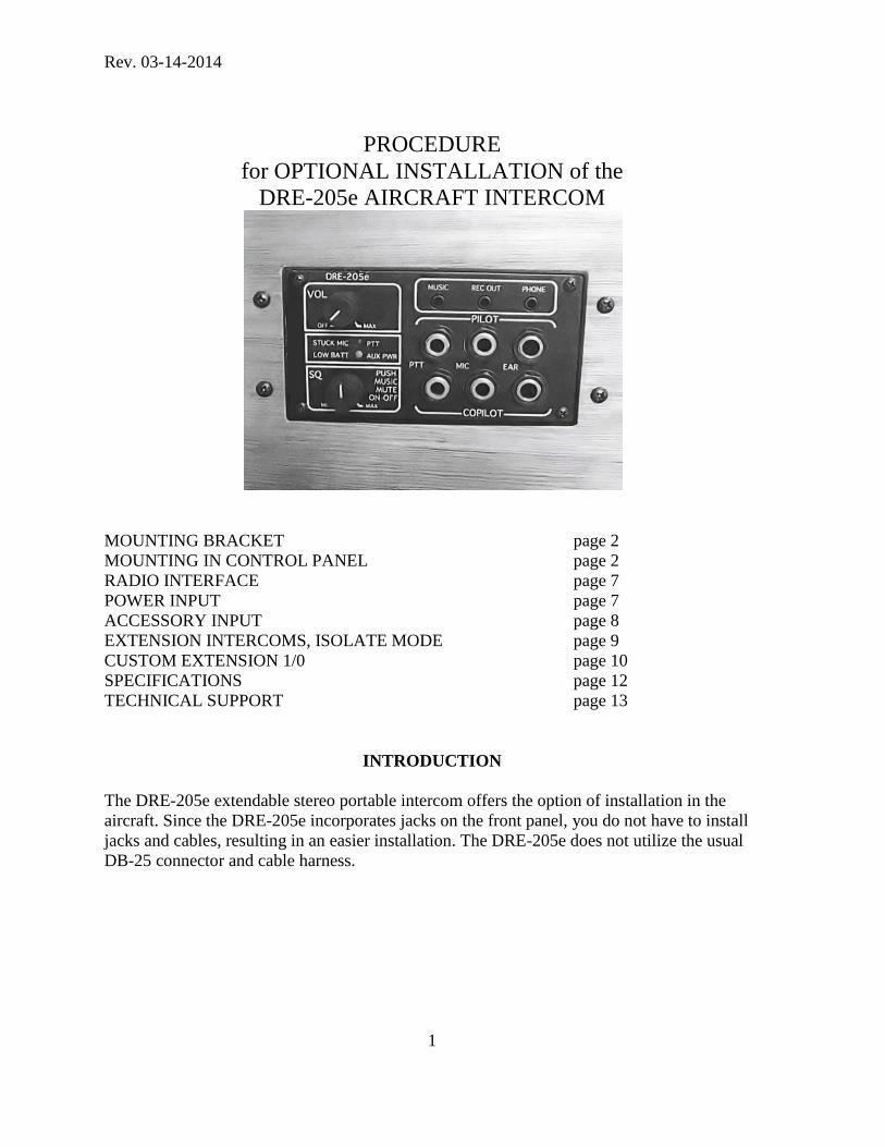
PROCEDURE
for OPTIONAL INSTALLATION of the
DRE-205e AIRCRAFT INTERCOM
Rev. 03-14-2014
PROCEDURE
for OPTIONAL INSTALLATION of the
DRE-205e AIRCRAFT INTERCOM
MOUNTING BRACKET page 2
MOUNTING IN CONTROL PANEL page 2
RADIO INTERFACE page 7
POWER INPUT page 7
ACCESSORY INPUT page 8
EXTENSION INTERCOMS, ISOLATE MODE page 9
CUSTOM EXTENSION 1/0 page 10
SPECIFICATIONS page 12
TECHNICAL SUPPORT page 13
INTRODUCTION
The DRE-205e extendable stereo portable intercom offers the option of installation in the
aircraft. Since the DRE-205e incorporates jacks on the front panel, you do not have to install
jacks and cables, resulting in an easier installation. The DRE-205e does not utilize the usual
DB-25 connector and cable harness.
1

Rev. 03-14-2014
MOUNTING BRACKETS
Optional brackets are available for mounting the intercom. There is no need to drill in the
205e enclosure box. The closed-ended slots of the brackets are designed to give a range of
mounting depths in order to accommodate various thicknesses of control panels, and different
possible mounting placement, whether the brackets mount out in front of the panel or behind it.
The recommended method for installing the brackets is covered below.
MOUNTING IN CONTROL PANEL
The following pictures show mounting the 205e in a 1/8” piece of wood panel for illustration
purposes.
If the battery compartment will be inaccessible after installation, be sure to remove the
batteries first.
For brackets in front of the panel: Make the hole in the panel 2.525" tall and 4.825" long.
This length leaves room for the bracket and the screws that hold the brackets to the sides of the
intercom case. The brackets will help hide any imperfections in the cuts at the ends. For a more
exact fit, make the hole slightly smaller and file as necessary. Be careful not to get any
shavings or filings into the intercom.
Because the battery compartment extends out approximately about 1/8" from the intercom case,
you will not be able to put the intercom into the panel from the front. Bring it through the hole
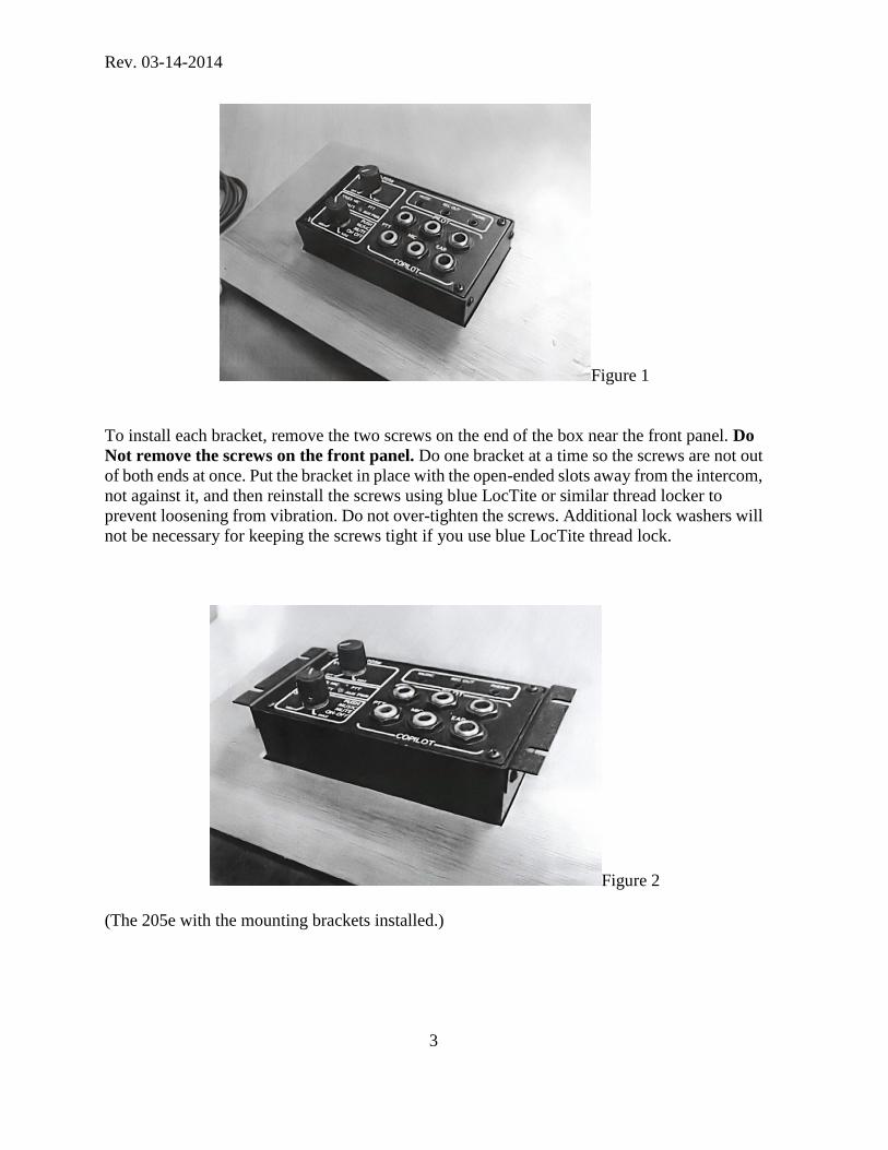
from the rear (shown in Fig. 1), and then add the brackets.
2
Rev. 03-14-2014
Figure 1
To install each bracket, remove the two screws on the end of the box near the front panel. Do
Not remove the screws on the front panel. Do one bracket at a time so the screws are not out
of both ends at once. Put the bracket in place with the open-ended slots away from the intercom,
not against it, and then reinstall the screws using blue LocTite or similar thread locker to
prevent loosening from vibration. Do not over-tighten the screws. Additional lock washers will
not be necessary for keeping the screws tight if you use blue LocTite thread lock.
Figure 2
(The 205e with the mounting brackets installed.)
3

Rev. 03-14-2014
Figure 3
Push the intercom back into the hole, and use the bracket slots as a template to mark where to
drill holes for the mounting screws. The slots in the brackets are intended for 6-32 screws. You
can use nuts behind the panel to secure the screws, or use a smaller drill bit and thread the panel
itself. In either case, use Blue LocTite or other suitable thread locker to make sure the screws
cannot loosen from vibration.
With screws installed:
Figure 4
To install with brackets behind the panel: Cut the mounting hole 2.525" tall and 4.565" long.
With the brackets behind the panel instead of in front, they will not aid in hiding any
imperfections in the cut, so the ends of the mounting hole will have to be cut as precisely as the
top and bottom. For the most exact fit, make the hole slightly smaller and file as necessary. Be
careful not to get any shavings or filings into the intercom.
4

Rev. 03-14-2014
To install each bracket, remove the two screws on the end of the box near the front panel. Do
Not remove the screws on the front panel. Do one bracket at a time so the screws are not out
of both ends at once. Put the bracket in place with the open-ended slots away from the intercom,
not against it, and then reinstall the screws using blue LocTite or similar thread locker to
prevent loosening from vibration. Do not over-tighten the screws. Additional lock washers will
not be necessary for keeping the screws tight if you use blue LocTite thread lock.
While installing the brackets set them to the appropriate height to make the intercom's panel
flush with the control panel you're mounting it in.
Figure 5
Figure 5 shows the bracket set down low for the thickest panel.
Figure 6
Figure 6 shows a correct flush mount setting.
5

Rev. 03-14-2014
Figure 7
With the brackets now installed, place the intercom into the hole backwards (facing into the
panel), and mark the location of the mounting screw holes using the bracket slots as a template
as shown in figure 7.
The slots in the brackets are intended for 6-32 screws. You can use nuts behind the panel to
secure the screws, or use a smaller drill bit and thread the panel itself. In either case, use Blue
LocTite or other suitable thread locker to make sure the screws cannot loosen from vibration.
Reinstall the intercom into the mounting hole in the instrument panel and attach with 6-32
screws.
The finished mounting (figure 8).
Figure 8
6

Rev. 03-14-2014
RADIO INTERFACE
If you are installing the intercom, you may need to remove the plugs and Y-block at the end of
the radio-interface cable and solder it directly to the equipment in the aircraft. The wire colors
in the cable are as follows:
• The green wire, as well as the tip of the larger plug, carries the radio earphone
signal to the intercom.
• The black wire, as well as the sleeve of the larger plug, is the ground (low) for
the radio earphone signal
• The blue wire, as well as the tip of the smaller plug, carries the PTT signal.
Shorting it to ground makes a PTT-true condition.
• The yellow wire, as well as the center ring of the smaller plug, is the
intercom's mic-to radio line, carrying the mic signal for the radio to transmit.
• The white wire, as well as the sleeve of the smaller plug, is the ground (low)
for the mic-to-radio and PTT lines.
The black wire, white wire, and shield are connected together inside the intercom. At the cable's
end opposite the intercom, connecting the shield is not necessary, or even desirable in some
cases.
Although it is not expected that these colors will change, it is a good idea to double-check the
above colors before soldering, by using a continuity meter on the part of the cable that you cut
off, from each color to the plugs.
You can have a PTT that is separate from the DRE-205e intercom for the pilot, typically
mounted on the control stick. A copilot PTT must be plugged into the front of the intercom to
have this function.
POWER INPUT
The power cord supplied with the intercom has a cigarette-lighter style plug on one end and
DC-10 on the other. The DC-10 plug has a .080” (2mm) center hole which is positive. The
outside is ground. For installation purposes, you will want to remove the cigarette-lighter plug
and connect the cord to power through a 2-amp fuse or circuit breaker. Be careful to ensure the
center hole in the DC10 plug is connected to positive before plugging in the intercom to avoid
damage to the intercom circuitry.
The intercom power should be supplied through the master switch, otherwise, the intercom will
drain approximately 13mA of current even if the volume switch is in the off position. The green
AUX PWR / LOW BATT LED stays lit if power is still being supplied. When the intercom is
on and has headsets plugged in, it will draw approximately 70mA.
7

Rev. 03-14-2014
There is no need to filter the input power. The power supply in the intercom is double regulated
and can handle a huge amount of power line noise without passing it through to the audio.
If you do experience noise in your headsets, it is likely due to a bad grounding scheme which
causes the noise to enter through the audio inputs, not the power input.
The possibility of a bad ground scheme is reduced with the 205e as all connections are built in
to the intercom. The box and the mounting brackets are anodized, but do not guarantee
insulation from your aircraft panel. If the intercom and the equipment it is interfaced to are all
close together (as will be typical for DRE-205e installations), you should not have any ground
issues.
ACCESSORY INPUT
The DRE-205e does not come supplied with any audio patch cables for the accessory (ACC)
input. Various retailers have ones that will work. Radio Shack (www.radioshack.com) stock
numbers 42-223 (3 feet long) and 42-435, 42-2387, and 42-2607 (all three being 6 feet long)
should all work well. You do not really need shielding or gold plugs, just three conductors.
The 3.5mm 3-conductor Accessory (ACC) input phone jack has no outputs, but instead has two
separate but identical input channels, one on the tip and one on the center ring with the sleeve as
ground. Do not confuse these two channels with the left and right of a stereo input. Although
the intercom is stereo, these two inputs are not intended for music. They are two separate but
identical monophonic inputs, and both supply both ears of each headset. They are intended to
be used as inputs from, for example, a GPS or engine monitor. Audio from either of these inputs
will be heard even in the ISOlate mode (which disconnects the EXTension ports), and will mute
music regardless of the muting mode.
Be sure the plugs you use are very clean and inserted all the way, so as to keep the contacts
reliable. With the intercom installed in the instrument panel, they will not be accessible.
8

Rev. 03-14-2014
EXTENDING the INTERCOM to 4- or 6-PLACE, plus ISOLATE MODE
You can use two 205e intercoms connected together for a true 4-place intercom. A cable is
available from DRE, p/n D205eEXT, and is labeled, "INTERCOM EXTENSION". If you want
to make your own cable, the last paragraph of this section tells how. Use the cable to connect
the intercoms together at their EXT1 or EXT2 jacks on the left end of each intercom. A
standard music cable will not work for this! The EXT1 and EXT2 jacks are two separate but
identical 1/0 ports, so it does not matter which one you use on either intercom. With the
intercom installed, these jacks and the cords plugged into them will normally be hidden by the
instrument panel.
Additionally, you can use three 205e intercoms for a true 6-place. Make the same connections
as above for the additional intercom, plus a third cord to connect the two extension intercoms
together.
Each intercom can use its own phone and music sources. The only audio that gets shared over
the extension connections is the intercom audio from the microphones. None of the other audio
sources at any given intercom will be heard on the other intercom(s). The music-muting mode
choice on one 205e will also not affect what is heard on another 205e connected to it.
To isolate a particular intercom from the others, whether for privacy or other reason, use the
ISOlate mode. To activate the ISOlate mode, press the volume knob. Press it a second time to
cancel ISOlate mode. There is no front-panel indication for ISOlate on or off.
Making an EXTENSION Cable
If you make your own EXTension cables (such as to use right-angle plugs), here's what you
need to know. All intercoms' EXT1 and EXT2 jacks put their signal out on the tip of the plug,
and return the input on the center ring. Make your cable so that the tip of one plug goes to the
center ring of the other, and vice-versa. The sleeve is ground at both ends, so this one
connection does go straight across. Using shielded cable is preferable for long runs, but may not
be necessary for short ones. Either way, you need three conductors total, whether or not one of
them is a shield.
You will need two 3.5mm 3-conductor phone plugs.
9

Rev. 03-14-2014
CUSTOM EXTENSION I/0
The same EXTension ports discussed above can be used for other things besides expanding the
intercom with an extension intercom. Each EXT port has an input and an output.
The output carries a mix of only the two mic signals (after squelch, but before the volume
control). No other input to the intercom—neither music, radio, phone, accessory, or the other
EXT input—will get reproduced in the EXT output.
The input gets mixed in just before the volume control, and the signal will mute music if music
muting is enabled. The input signal makes its way only to that one intercom's earphone outputs
(and recorder output), and will not get reproduced in the mic-to-radio output, the phone output,
or the other EXT output.
There is no requirement to use both input and output. You may have an application that needs
only the inputs, or only the outputs, or where the input and output are unrelated; I.E. where the
input comes from one device and the output goes to another. Unused contacts should be left
unconnected.
As with the extension intercom(s), going into ISOlate mode essentially does the same thing as
removing the plugs from the EXT1 and EXT2 jacks. You can go in and out of isolate mode by
pressing the volume knob. There is no front-panel indication for ISOlate on or off
Here is an example of connecting a separate (auxiliary) communication radio. Depending on
the mic-input requirements of the radio, you can probably connect the intercom's EXT output
(from the tip contact of the 3.5mm plug) directly to the mic input of the auxiliary radio. It will
not cause any damage; but if the transmit modulation is too high or low, we may need to add a
small amount of circuitry. Contact Headsets Inc. if you need help.
• EXT plug tip to mic input of the auxiliary radio
• EXT plug center ring to earphone output of the auxiliary radio
• EXP plug sleeve to ground of the auxiliary radio
• PTT circuit as needed by the auxiliary radio
10

Rev. 03-14-2014
You might find that the equipment you connect to the EXT ports has a DC bias on one line or
the other. It is not a problem, as long as it is not over 12 volts.
Since the EXTension ports' outputs carry both mic signals, you will typically want one person
silent when the other person transmits on the auxiliary radio. The mix of mic signals is
post-squelch, so you will not transmit noise from the unused mic.
If you wish to connect a cable for future use, various retailers have ones that will work. Radio
Shack (www.radioshack.com) stock numbers 42-223 (3 feet long) and 42-435, 42-2387, and
42-2607 (all three being 6 feet long) should all work fine. You don't really need shielding or,
gold plugs, just three conductors.
To interface an EXTension port in your own custom setup, you need to know that EXT1 and
EXT2 jacks put their signal out on the tip of the plug, and bring in the input on the center ring.
The sleeve of the plug is ground, as usual. Using shielded cable is good for long runs. It is three
conductors total, whether or not one of them is a shield.
Be sure the plugs you use are very clean and inserted all the way, so as to keep the contacts
reliable, as they will not be accessible to move during flight.
11

Rev. 03-14-2014
SPECIFICATIONS
Note: These are actual measurements from a 205e. Frequency responses are at the -3dB points.
Music:
gain: 2.8, non-inverting
input impedance: 1 KΩ
frequency response: 18Hz-40kHz
THD at 1 VRMS out and 400Hz: TBD (was 0.25% @ 1 kHz, 2VRMS
output on 244e, and is expected to be
better on 205e)
signal-to-noise ratio: 78dB
music muting: 20dB
channel separation: >60dB @ 1kHz
Radio:
gain: 1 (even when unit is turned off)
input impedance: 500Ω
frequency response: 14Hz-40kHz Radio reception always
mutes music.
Intercom:
maximum mic input: 10Vp-p without clipping (with low vol
setting)
mic input frequency response: 100Hz-7kHz
Isolation in ISOlate mode: >74dB @ 1 kHz incoming, 61dB
outgoing @ 1 kHz
Output: Automatic mono/stereo compatible,
intended for common G/A earphones of
75 to 300 ohms per ear
max output signal voltage: >8Vp-p at earphones.
Accessory inputs: 75K0, two identical mono channels
designed to accept instrument audio.
Signal input always mutes music.
Phone interface: designed to plug into cell phones like a
miniature corded earphone/microphone
pair (pin out same as extension ports)
12
Rev. 03-14-2014
Extension ports: signal out on plug tip, in on plug center
ring.
Output level: same as the G/A mics but 61KΩ,
Input load: approx 25KΩ
Power: 10V to 30V input, 70mA typical. Use 2A
fuse or circuit breaker, to master switch.
TECHNICAL SUPPORT
We find that many users have special applications they want help for, even if there is no actual
problem with the intercom. If you have questions or need help, contact Garth Wilson at
[email protected], or (562)695-7054.
13