interconnections and communications of electric vehicles...
TRANSCRIPT

Interconnections and Communications of Electric Vehicles and Smart Grids
Sebastian Käbisch University of Passau
Chair of Distributed Information Systems 94032 Passau, Germany
Anton Schmitt, Martin Winter, Jörg Heuer Siemens AG, Corporate Technology
Communication Systems & Control Networks Munich, Germany
{Anton.Schmitt, Martin.Winter, Joerg.Heuer}@siemens.com
Abstract—Huge investigations have to be made by car and power companies to realize the electro-mobility and the corresponding infrastructure. One of the critical challenges with respect to the infrastructure is the setup and deployment of a future-proof common standard for smart grids. The charging process requires a smooth communication between electrical vehicles, the power supply equipment and the smart grid. In this regard, different kind of charging locations, the charging characteristic as well as several vehicle to grid stakeholders have to be considered. This paper discusses the vehicle to grid integration and gives an overview of the current ongoing working assumption in the international joint ISO/IEC standardization of the vehicle to grid communication interface (V2G CI). Furthermore, the paper shows an approach how this communication interface can be integrated into the smart grid communication. First project results are presented demonstrating the successful implementation of this approach.
Keywords: smart grid; ISO/IEC V2G CI; IEC61850
I. INTRODUCTION
Electrical vehicles (EVs) are a radical shift not only in how a vehicle is build but also how it is integrated into the power supply infrastructure. For instance, with fixed mounted batteries the vehicle will no longer be fueled during a stop over at a gas station but be charged at home, at work, during shopping on a parking place or even fast charged during a stop over. However this requires a standardized interface so that the vehicle from X can be charged at the location of Y.
Now you can say this is not the first issue to solve when introducing electrical vehicles. Choosing one of the legacy interfaces available for other domains of electrical power supply would be sufficient. On the other hand especially with the currently available EVs, which are significantly limited in their reach, the availability of charging infrastructure is crucial. The charging infrastructure investment can only have a good return on investment if the interoperability and scaling of the interfaces is guaranteed. Thus the market introduction of EVs beyond dedicated field trials strongly depends on a standardized vehicle to grid (V2G) interface.
What are the use cases for this V2G interface or more general the charging? In the next years EVs are envisaged to become commonplace for everyone. At first, the EV will only
be used for small distance trips such as the drive to work. It is expected, however, that in the next 20 years EVs will also be suitable for long distance travel and replace conventional vehicles more and more. In any case, to enable a mass market the charging process of an EV has to be as simple as connecting any other electrical device.
Especially taking the charging at home under account, which will be at the beginning a major use case, an EV is different than other electrical devices. The load, which an EV represents for the power grid, is much higher as the normal energy consumption of a household today. Take under account that the capacity of an EV with its 30kWh is capable to run a 4 person household for a few days. And at the same time an EV should be rechargeable over night.
Another use case is the charging of the vehicle in public or semi-public places such as company parking places. Taking into account that the user is not willing to control complex processes the charging process has to be highly automated. This includes an automation of the authorization, operation and billing. The billing of the electrical energy can not be directly mapped to the electrical connection point of the grid as it is managed in the households today, because the Electric Vehicle Supply Equipment (EVSE) is shared by many consumers. A temporal association between the EV and the EVSE has to be automatically initiated for the charging process when the charging cable is inserted.
These examples illustrate that a standardized interface of EVs to the grid is required if the introduction of EVs are seriously considered. Due to the significance of the load it is also evident that the interface has to offer the capability to balance the load and to provide further functionalities such as authentication to maintain simplicity of operation e.g. for public or semi-public deployment. Regarding the use cases described above it is obvious that the V2G interface is not only a power but also a communication interface.
In this paper we are focusing on the V2G Communication Interface standardization and study the integration of the EV into the smart grid. Section II contains an analysis of the different stakeholders which have to be taken into account for the definition of the V2G interface. Section III describes the current working assumption in the international joint ISO/IEC standardization of the V2G communication interface. In section
This research is supported by the German Federal Ministry for theEnvironment, Nature Conservation and Nuclear Safety within the Harz.EE-mobility project under contract 03KP623.
978-1-4244-6511-8/10/$26.00 ©2010 IEEE 161
IV the integration into available smart grid technologies is discussed and practical examples of implementations, which are developed in the context of publicly funded projects, are described in section V. Finally an outlook based on the ongoing projects and field trials are given.
II. VEHICLE-TO-GRID STAKEHOLDERS
Already the use cases described above lead to a conglomerate of stakeholders for the market introduction of EVs, which have to be involved in the ‘simple’ charging process of an EV without increasing the complexity for the EV user, who is just used to plug in a connector. What are now the stakeholders involved in the charging process?
On the car side there is the car driver, who may have different options to pay for the energy e.g. by cash, credit cards, electronic payments or contract based payment methods. Furthermore the car owner or fleet operator may be involved in the charging process. The latter might operate the fleet based on business models taking also demand side management into account. Besides these two parties also the car producer, which sells the car with a special mobility service, may be involved in the payment process.
In public or semi-public places beside the payment for charging also the authorization for the charging process has to be implemented by a so called identity provider. The identity provider might also act as a clearing house for the whole payment process. In addition the customer is directly faced with the infrastructure provider, which may be in the public place an agency, which supports the discrimination-free supply of energy on the EVSE. In this case several energy service provider types are possible which provide energy via this EVSE such as a pure energy supplier, an energy retailer or a demand response operator, who is actively influencing the charging process [1].
In a semi public area it may be a different situation as the owner for example of a parking deck may charge for the parking itself and act at the same time as an energy provider. So the mixture of parking fees and energy costs may not be obvious for the customer.
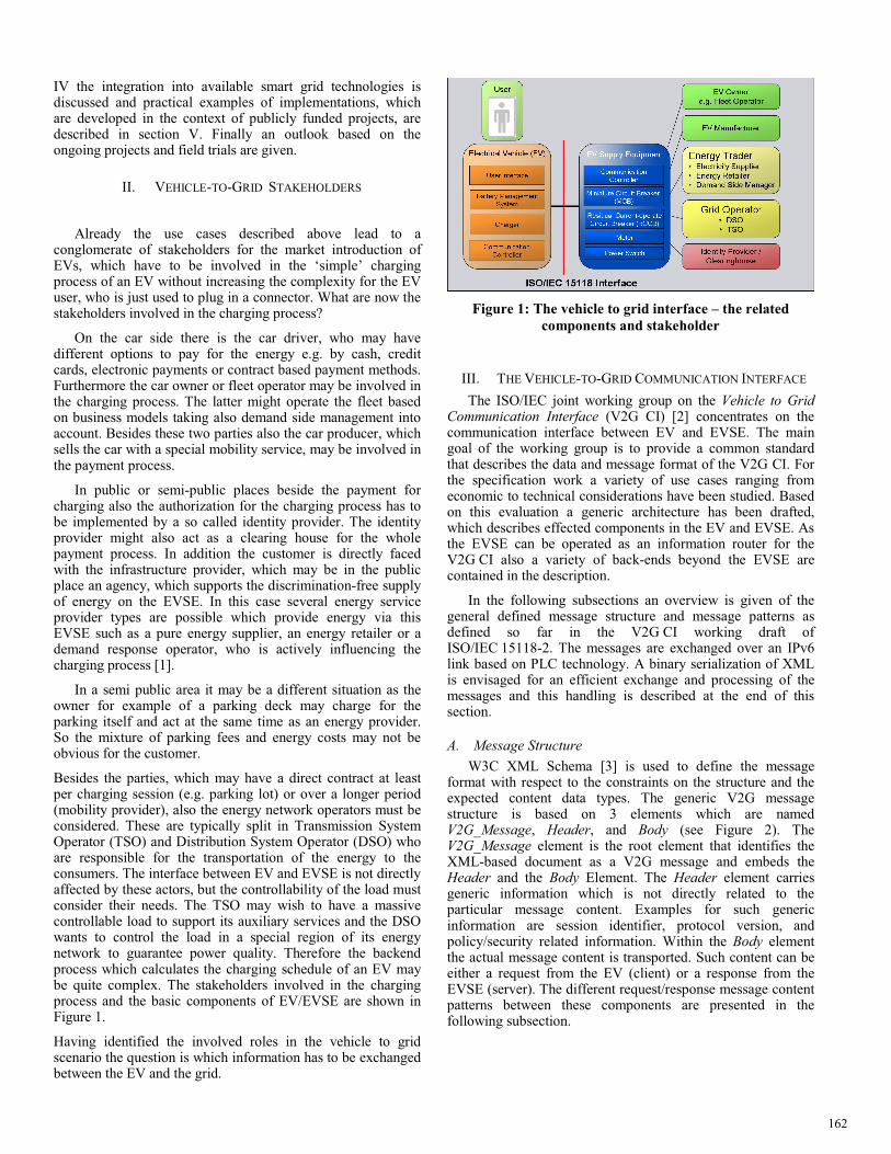
Besides the parties, which may have a direct contract at least per charging session (e.g. parking lot) or over a longer period (mobility provider), also the energy network operators must be considered. These are typically split in Transmission System Operator (TSO) and Distribution System Operator (DSO) who are responsible for the transportation of the energy to the consumers. The interface between EV and EVSE is not directly affected by these actors, but the controllability of the load must consider their needs. The TSO may wish to have a massive controllable load to support its auxiliary services and the DSO wants to control the load in a special region of its energy network to guarantee power quality. Therefore the backend process which calculates the charging schedule of an EV may be quite complex. The stakeholders involved in the charging process and the basic components of EV/EVSE are shown in Figure 1.
Having identified the involved roles in the vehicle to grid scenario the question is which information has to be exchanged between the EV and the grid.
Figure 1: The vehicle to grid interface – the related components and stakeholder
III. THE VEHICLE-TO-GRID COMMUNICATION INTERFACE
The ISO/IEC joint working group on the Vehicle to Grid Communication Interface (V2G CI) [2] concentrates on the communication interface between EV and EVSE. The main goal of the working group is to provide a common standard that describes the data and message format of the V2G CI. For the specification work a variety of use cases ranging from economic to technical considerations have been studied. Based on this evaluation a generic architecture has been drafted, which describes effected components in the EV and EVSE. As the EVSE can be operated as an information router for the V2G CI also a variety of back-ends beyond the EVSE are contained in the description.
In the following subsections an overview is given of the general defined message structure and message patterns as defined so far in the V2G CI working draft of ISO/IEC 15118-2. The messages are exchanged over an IPv6 link based on PLC technology. A binary serialization of XML is envisaged for an efficient exchange and processing of the messages and this handling is described at the end of this section.
A. Message Structure W3C XML Schema [3] is used to define the message
format with respect to the constraints on the structure and the expected content data types. The generic V2G message structure is based on 3 elements which are named V2G_Message, Header, and Body (see Figure 2). The V2G_Message element is the root element that identifies the XML-based document as a V2G message and embeds the Header and the Body Element. The Header element carries generic information which is not directly related to the particular message content. Examples for such generic information are session identifier, protocol version, and policy/security related information. Within the Body element the actual message content is transported. Such content can be either a request from the EV (client) or a response from the EVSE (server). The different request/response message content patterns between these components are presented in the following subsection.
162
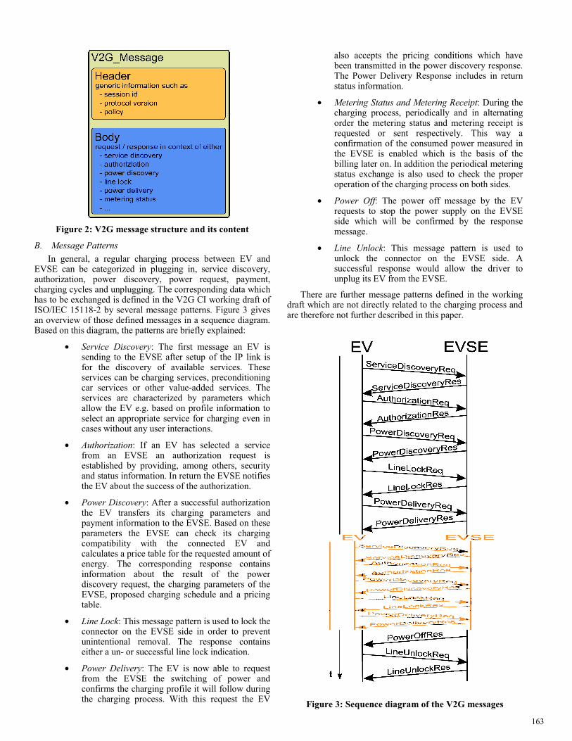
Figure 2: V2G message structure and its content
B. Message Patterns In general, a regular charging process between EV and
EVSE can be categorized in plugging in, service discovery, authorization, power discovery, power request, payment, charging cycles and unplugging. The corresponding data which has to be exchanged is defined in the V2G CI working draft of ISO/IEC 15118-2 by several message patterns. Figure 3 gives an overview of those defined messages in a sequence diagram. Based on this diagram, the patterns are briefly explained:
• Service Discovery: The first message an EV is sending to the EVSE after setup of the IP link is for the discovery of available services. These services can be charging services, preconditioning car services or other value-added services. The services are characterized by parameters which allow the EV e.g. based on profile information to select an appropriate service for charging even in cases without any user interactions.
• Authorization: If an EV has selected a service from an EVSE an authorization request is established by providing, among others, security and status information. In return the EVSE notifies the EV about the success of the authorization.
• Power Discovery: After a successful authorization the EV transfers its charging parameters and payment information to the EVSE. Based on these parameters the EVSE can check its charging compatibility with the connected EV and calculates a price table for the requested amount of energy. The corresponding response contains information about the result of the power discovery request, the charging parameters of the EVSE, proposed charging schedule and a pricing table.
• Line Lock: This message pattern is used to lock the connector on the EVSE side in order to prevent unintentional removal. The response contains either a un- or successful line lock indication.
• Power Delivery: The EV is now able to request from the EVSE the switching of power and confirms the charging profile it will follow during the charging process. With this request the EV
also accepts the pricing conditions which have been transmitted in the power discovery response. The Power Delivery Response includes in return status information.
• Metering Status and Metering Receipt: During the charging process, periodically and in alternating order the metering status and metering receipt is requested or sent respectively. This way a confirmation of the consumed power measured in the EVSE is enabled which is the basis of the billing later on. In addition the periodical metering status exchange is also used to check the proper operation of the charging process on both sides.
• Power Off: The power off message by the EV requests to stop the power supply on the EVSE side which will be confirmed by the response message.
• Line Unlock: This message pattern is used to unlock the connector on the EVSE side. A successful response would allow the driver to unplug its EV from the EVSE.
There are further message patterns defined in the working draft which are not directly related to the charging process and are therefore not further described in this paper.
Figure 3: Sequence diagram of the V2G messages
163

C. Efficient Data Exchange of V2G Messages Significant investigations have to be made by car and
power companies to realize a smart integration of e-mobility and the corresponding infrastructure into today’s power grid. To avoid investigation-costs the applicability of future proof and widely supported XML technologies also in embedded systems has been evaluated.
Embedded devices are typically heavily resource-constrained in terms of memory usage and processing capabilities. In this context usage of the V2G messages in a plain-text XML has significant disadvantages due to the known XML parsing overhead and its memory usage. Binary XML addresses this issue by a computational efficient binary serialization of XML. Based on recent evaluations the usage of W3C’s Efficient XML Interchange (EXI) [4] format to realize the V2G-based interaction has become working assumption.
The EXI format uses a relatively simple grammar driven approach that achieves very efficient encodings for a broad range of use cases [5]. The EXI specification describes a predefined process how schema information is to be transformed into EXI grammar. The reason for doing so is that EXI grammar is much simpler to process, compared to XML Schema information. Nevertheless the parsing can be performed in the same accurate way as it is possible in XML. The successful and efficient usage of XML-based communication by means of EXI in embedded components - even if small microcontrollers are involved - was shown for instance in [6].
IV. MAPPING OF V2G CI TO 61850 So far the vehicle to grid interface has been described from
the perspective of the EV. The integration of e-mobility into the smart grid requires a different viewpoint: instead looking from the EV to the EVSE we have to take the perspective from the smart grid to the EVSE. As described in [7] for the smart grid integration of distributed energy resources a homogeneous modelling of the variety of different resources is crucial. Due to the magic of scale this is a prerequisite to enable an integration of a significant number of resources which are balancing each other and this at reasonable costs. To achieve this homogeneous modelling the Distributed Variable Energy Resource (DVER) model was introduced based on the IEC 61850-7-420 specification [8]. Starting from this application setup we describe in the following how the EVSE can map information of the power discovery and charging operation phase into the DVER model. This enables the integration of EVs or EV fleets into a massively distributed virtual power plant (VPP) as a part of the smart grid.
A. Basics of IEC 61850 Architecture Model IEC 61850 [8] uses a hierarchical model to describe energy
systems. The model comprises the following components:
A server offers a defined communication access to a dedicated component in the power grid. For each server certain communication parameters are defined, e.g., an IP-address and a port number. A server contains one or more logical devices,which present a logical view on the energy facility or parts of it. Logical devices can be set up for e.g. a wind power plant or a controllable load.
A logical device comprises a certain amount of logical nodes (LN) which describe certain partial aspects of the device.
A combined heat power generator, for example, contains the LNs ‘motor’ and ‘heat store’. IEC 61850 describes a LN by name and a complex data class. In the data class certain data values of LNs are defined. There are four types of data values:
• Status information: data that describes the state of logical nodes; status information is read-only
• Settings: changeable configuration values • Measurement values: readable values • Controls: offer the possibility to carry out switching
operations in a facility
Data classes can be structured in an hierarchal order. Additionally, a data class may contain data attributes which are either primitive or composed data types. For example, a primitive data attribute may contain the measurement value itself, the corresponding unit, and the actual time stamp. More examples of such hierarchy can be found, among others, in IEC 61400-25-4 [13].
B. Extension of IEC 61850 for DVERs We started modelling the DVERs with the existing data
definitions standardised in IEC 61850-7-420 [13]. The standard is capable of describing a DVER in very detail. The specific information is necessary to operate the particular energy resource by all means. If it comes to a huge number of EVs, however, this results in a massively distributed system. In such a system a generic abstraction of the variety of energy resources is required. The objective is to control the operation of a VPP that represents a huge number of different plant types with abstracting the relevant specifics of a single plant type. For this purpose a generic DVER model for all different plant types is specified based on the data types used in IEC 61850.
Having described the characteristics of different DVERs (see [7]), basic parameters for DVERs were derived by extracting a common parameter set from the parameter values of the various plant types. One and the same parameters is thereby technically realised totally different for each plant type. The only importance is that the impact on the power grid is the same. The LN build out of the parameters shall only describe the electrical behaviour of the plant independent of the technology used. In the following the developed parameter set is described in detail:
1) Maximum supply power: The maximum power the plant can draw from the electrical grid.
2) Maximum feeder power: The maximum power the plant can emit into the electrical grid.
3) Step-less yes/no: Tells whether the power drawn from or emitted into the electrical grid can be adjusted continuously, whether it is just possible to use fixed values or whether supply and feeder can simply be switched on and off.
4) Total storage capacity: The variability of any controllable energy plant can be described by a real or virtual storage capacity. This parameter describes the capacity which the plant operator likes to provide externally.
5) Current charging level: Only applicable for plants with storage to signal the current charging or filling level. The information is provided in units of energy amount. A percentage can be calculated with the
164

quotient of current state and total capacity. Plants without storage signal a value of 0.
6) Storage efficiency: Storage efficiency is the rate of stored energy amount to potentially withdraw-able energy amount. To empty the storage a storage efficiency of 100% is assumed.
7) Start- and endpoint: Especially designed for EVs, this parameter tells the points in time when charging starts and ends or when a given minimum charging state shall be reached (see following parameter).
8) Minimum target energy amount: Also meant for EVs, this parameter is used to specify the target energy amount to be reached at a given point in time.
9) Minimal charging state trajectory: In some cases it is not sufficient to specify only the target energy amount and the end of charging time. Therefore a charging state trajectory shall be available to describe the minimum charging state for a given point in time.
10) External feeder: Biogas plants with gas storage or storage power stations have a continuous external energy feed that fills the storage with gas or water. In contrast, e.g., some battery technologies have a steady loss of energy that reduces the filling or charging level. This parameter describes which power is fed to (positive) or emitted from (negative) the storage.
C. Implementation based on Web Protocols In the case of including EVSEs (and thus EVs) in a VPP
the DVER model must be communicated between the EVSE respectively EV and the VPP control center. To cope with the scalability in such a VPP, the communication between the resources has been implemented on Web technologies. Especially, the usage of the wide-spread Web Services (WS) [9] enables a set of reliable protocols which supports a variety of required functionalities such as self configuration, security aspects (WS-Signature, WS-Encryption) [10] and event driven communication (WS-Eventing) [11]. The status of each distributed energy resources can efficiently be tracked based on a registry and keep-alive messages. To support this approach even in very restricted communication environments such as those based on wireless or PLC links, the Efficient XML Interchange format [4] is used.
D. Mapping of V2G CI to DVER For the mapping of services from the EV side to the smart grid side it has to be considered that the EVSE is operated in both domains as a server. Thus a mapping of requests to requests and responses to responses is not possible. On the smart grid side the EVSE is described by a DVER data model which is modified according to the connected EV each time an EV is hooked up. Modifications are reported by the functionality of the ACSI services described in IEC 61850-7-2 [9] respectively the mapping on web services according to IEC 61400-25-4 [13]. Thus the VPP controlling the EVSE is waiting for reports from the EVSE. In case an EV is plugged into the EVSE and after selecting a particular charging service (see section III) the EV sends the power discovery request, which contains the overall requested power demand, time frame information and charging capabilities. These values are then transmitted in a report, which signals a change in the DVER instance as part of the DVER data model to the VPP control centre. The VPP
control centre replies by a SetDataValues command, which is defined in the Abstract Communication Service Interface (ACSI) part of the IEC 61850-7-2, that modifies the charging Distributed Energy Resource Schedule (DSCH). DSCH is part of the data structure in the EVSE LN, where the EV is located. This information is then forwarded in the power discovery response to the EV. After the line lock the schedule is confirmed by the vehicle in the power delivery request. The EVSE checks back this confirmation, and signals readiness to switch on the power in the response to the EV. The charging of the EV is monitored by mapping the MeteringReceiptReq to ACSI Reports service reflecting updates of the DVER. If during the charging a modification of the charging schedule is required a SetDataValues ACSI Request is sent from the VPP center to the EVSE. The EVSE signals the request for renegotiation of the remaining schedule in the MeteringReceiptRes which results in a renegotiation as described for the initial charging schedule negotiation (see section III) but parallel to the continuing charging process. Finally with the PowerOffReq a concluding ACSI Report is transmitted to the VPP center.
Figure 4: Message mapping of V2G to IEC 61850
V. IMPLEMENTATIONS
The described approach is successfully implemented by the authors in the context of the research project Harz.EE-mobility [14]. The project addresses the challenge to use the introduction of electrical vehicles to also improve the grid integration of local renewable energy sources and at the same time to reduce the carbon footprint of the individual mobility. From the smart grid and VPP perspective electric vehicles are a
165

promising mean of load balancing in smart grids. The presented approach is adapted to this domain by modelling the charge spot as a DVER with a time varying characteristic depending on the vehicle connected to it.
Figure 5: EV and EVSE setup for VPP integration based on IEC 61850
In Figure 5 a first setup of an EVSE and EV is shown supporting the described V2G CI and the mapping to IEC 61850. While this has been implemented so far only for the AC charging case, in the EU research project EDISON [15] also the applicability of the described approach to the DC charging case will be studied.
Figure 6: Mobile interface for user interaction with the charging process
The wide range of opportunities which are enabled by a close coupling of the EV on the smart grid infrastructure are demonstrated by an application, which allows the interactive control of the charging process. The user is informed about the current charging status of his car, the available driving distance, charging time and price. This information can be retrieved via a backend server offering the mobile phone an
interface to request the charging status and to influence the charging process from anywhere (see Figure 6).
VI. SUMMARY AND OUTLOOK
In this paper we have described the basic principles of the V2G communication interface between the EV and EVSE currently under specification in the ISO/IEC. For the integration into the smart grid or more precisely into a VPP the mapping between the V2G CI and the commonly used IEC 61850 protocol suite was described. With this approach it has been shown, how the EVSE can provide the load balancing capabilities of a connected EV as a generic DVER within a VPP. Based on research projects first implementations of this approach have been discussed.
While the described mapping is mainly focused on the technical control communication of the V2G interface also administrative data has to be provided in the future. For this type of data the Common Information Model standard IEC61968 will be considered in the future. For the V2G integration especially at home further protocol mappings such as the upcoming Smart Energy 2.0 protocol of the HomePlug ZigBee Alliance will be evaluated in addition.
REFERENCES
[1] The impact of EU deregulation and marketisation policies on local government in EU member States: German local government and the provision of energy as a case in point, Prof. Dr. H. Wollmann, http://amor.cms.hu-berlin.de/~h0598bce/docs/HW-2007-Impact-of-EU-Regulation.pdf
[2] ISO TC 22/SC 3 JWG 1 http://www.iso.org/iso/iso_technical_committee.html?commid=46752
[3] David C. Fallside and Priscilla Walmsley, XML Schema Part 0: Primer Second Edition, http://www.w3.org/TR/xmlschema-0/, W3C Recommendation 28 October 2004
[4] J. Schneider and T. Kamiya, “Efficient XML Interchange (EXI) Format 1.0,” http://www.w3.org/TR/exi/, W3C Candidate Recommendation 08 December 2009.
[5] C. Bournez, “Efficient XML Interchange Evaluation”, http://www.w3.org/TR/exi-evaluation/, W3C Working Draft 7 April 2009.
[6] S. Käbisch, D. Peintner, J. Heuer and H. Kosch , „Efficient and Flexible XML-based Data-Exchange in Microcontroller-based Sensor Actor Networks”, Proceedings of IEEE International Conference on Advanced Information Networking and Applications Workshops (WAINA 2010), Perth, Australia, April, pp. 508-513
[7] J. Bergmann, C. Glomb, J. Götz, J. Heuer, R. Kuntschke und M. Winter, Scalability of Smart Grid Protocols, IEEE SmartGridComm 2010.
[8] IEC 61850-7-420: Communication networks and systems for power utility automation - Part 7-420. Norm IEC, 2009.
[9] Web Services Architecture, W3C, http://www.w3.org/TR/ws-arch/ [10] Web Service Security TC, OASIS, http://www.oasis-
open.org/committees/tc_home.php?wg_abbrev=wss [11] Web Services Eventing (WS-Eventing), W3C,
http://www.w3.org/TR/ws-eventing [12] IEC 61850-7-2: Basic communication structure for substation and feeder
equipment – Abstract communication service interface (ACSI). Norm IEC, 2003, http://webstore.iec.ch/preview/info_iec61850-7-2%7Bed1.0%7Den.pdf.
[13] IEC 61400-25-4: Communications for monitoring and control of wind power plants - Mapping to communication profile - Part 25-4. Norm IEC, 2008.
[14] HarzEE-mobility, https://www.harzee-mobility.de/ [15] EU FP7 research project EDISON, http://www.edison-
net.dk/About_Edison.aspx
166