interface control document for the common …cigi.sourceforge.net/files/cigi_icd_1.pdf · common...
TRANSCRIPT

Copyright Unpublished – 2001 All rights reserved under the copyright laws by The Boeing Company.
PO Box 516, St. Louis, MO 63166 Phone (314) 232-8888 Fax (314) 232 2187 e-mail [email protected]
Version 1: 14 March 2001
Report Number: TSS00I018
W. B. Phelps
®
INTERFACE CONTROL DOCUMENT for the
COMMON IMAGE GENERATOR INTERFACE
(CIGI)

Common Image Generator Interface TSS00I018 Version 1
ii
LIST OF PAGES
Title Page ii through v 1 through 86
The Boeing Company provides this document as is , without warranty of any kind, either expressed or implied, including, but not limited to, the implied warranties of merchantability and fitness for a particular purpose. The Boeing Company may make improvements and changes to the contents of this document at any time without notice. The Boeing Company assumes no responsibility for the use of the information in this document. This document may contain technical inaccuracies or typographical errors. Periodic changes are made to the information contained herein: these changes will be incorporated in new editions of the document.

Common Image Generator Interface TSS00I018 Version 1
iii
TABLE OF CONTENTS
Paragraph Page
1. SCOPE................................................................................................................................................................................. 6
1.1 PURPOSE .......................................................................................................................................................................6 1.2 INSTRUCTIONS FOR REVISING THIS DOCUMENT ......................................................................................................6 1.3 INTRODUCTION............................................................................................................................................................6
2. INTERFACE THEORY................................................................................................................................................. 7
2.1 MESSAGE PROTOCOL ..................................................................................................................................................7 2.1.1 Ethernet message synchronization......................................................................................................................... 7 2.1.2 Ethernet message frequency.................................................................................................................................... 7
2.2 ETHERNET PROTOCOL.................................................................................................................................................7 2.3 START UP SEQUENCE...................................................................................................................................................8 2.4 DATA PACKAGING.......................................................................................................................................................8
2.4.1 Floating-point format .............................................................................................................................................10 2.4.2 Fix-point format.......................................................................................................................................................10
3. COORDINATE SYSTEMS .........................................................................................................................................11
3.1 ENTITY POSITIONING.................................................................................................................................................11 3.2 ENTITY ORIENTATION...............................................................................................................................................12 3.3 ENTITY COORDINATE SYSTEM................................................................................................................................13
4. DATA PACKET NOMENCLATURE .....................................................................................................................14
4.1 DATA PACKET RELATIONSHIPS................................................................................................................................14 4.2 DATA PACKET DESCRIPTION....................................................................................................................................15 4.3 IG CONTROL..............................................................................................................................................................16 4.4 ENTITY CONTROL......................................................................................................................................................18 4.5 COMPONENT CONTROL ............................................................................................................................................26 4.6 ARTICULATED PART CONTROL...............................................................................................................................30 4.7 RATE CONTROL .........................................................................................................................................................34 4.8 ENVIRONMENT CONTROL........................................................................................................................................38 4.9 WEATHER CONTROL.................................................................................................................................................41 4.10 VIEW CONTROL.........................................................................................................................................................45 4.11 SENSOR CONTROL.....................................................................................................................................................48 4.12 TRAJECTORY DEFINITION........................................................................................................................................52 4.13 SPECIAL EFFECT DEFINITION...................................................................................................................................55 4.14 VIEW DEFINITION......................................................................................................................................................58 4.15 COLLISION DETECTION DEFINITION.......................................................................................................................63 4.16 HEIGHT ABOVE TERRAIN REQUEST .......................................................................................................................66 4.17 LINE OF SIGHT OCCULT REQUEST ..........................................................................................................................68 4.18 LINE OF SIGHT RANGE REQUEST ............................................................................................................................71 4.19 START OF FRAME ......................................................................................................................................................74 4.20 HEIGHT ABOVE TERRAIN RESPONSE......................................................................................................................77 4.21 LINE OF SIGHT RESPONSE ........................................................................................................................................79 4.22 COLLISION DETECTION RESPONSE .........................................................................................................................81 4.23 SENSOR RESPONSE ....................................................................................................................................................83
5. ERROR MESSAGES ....................................................................................................................................................85
6. ACRONYMS ...................................................................................................................................................................86

Common Image Generator Interface TSS00I018 Version 1
iv
TABLE OF FIGURES Figure Page FIGURE 1 - DATA INTERFACE CONNECTIONS................................................................................................................6 FIGURE 2 - CIGI/HOST ETHERNET SEND / RECEIVE SEQUENCING........................................................................7 FIGURE 3 - ENTITY POSITION IN GEODETIC LATITUDE AND LONGITUDE.....................................................11 FIGURE 4 - ENTITY ROTATION.............................................................................................................................................12 FIGURE 5 - ORDER OF ROTATION .......................................................................................................................................12 FIGURE 6 - ENTITY COORDINATE SYSTEM ....................................................................................................................13 FIGURE 7 - DATA PACKET RELATIONSHIP NOMENCLATURE...............................................................................14 FIGURE 8 - EXAMPLE OF DATA PACKET PARAMETER DIAGRAM.......................................................................15 FIGURE 9 - EXAMPLE OF DATA PACKET NARRATIVE ..............................................................................................15 FIGURE 10 - OBJECT CREATION USING AN ENTITY...................................................................................................19 FIGURE 11 - SINGLE PARENT / CHILD COMPONENTS ................................................................................................19 FIGURE 12 - MULTIPLE PARENT / CHILD COMPONENTS..........................................................................................20 FIGURE 13 - COMPONENT CONTROL COMPONENTS .................................................................................................26 FIGURE 14 - ARTICULA TED PART CONTROL COMPONENTS .................................................................................30 FIGURE 15 - RATE CONTROL COMPONENTS .................................................................................................................34 FIGURE 16 – VIEW POINT OFFSET AND ORIENTATION FROM ENTITY REFERENCE ...................................45 FIGURE 17 – SENSOR DEFINITION COMPONENTS .......................................................................................................48 FIGURE 18 – TRAJECTORY DEFINITION COMPONENTS............................................................................................52 FIGURE 19 - VIEW DEF INITION NOMENCLATURE.......................................................................................................58 FIGURE 20 - INDIVIDUAL DEFINITIONS FOR THREE VIEWS...................................................................................59 FIGURE 21- A GROUPING OF THREE INDIVIDUA L VIEWS .......................................................................................59 FIGURE 22 - VIEW THREE SEPARATED FROM A VIEW GROUP..............................................................................60 FIGURE 23 - GATE OFFSET AND SIZE................................................................................................................................83
TABLE OF TABLES Tables Page TABLE 1 - DATA PACKET IDENTIFICATION .....................................................................................................................9 TABLE 2 - EXAMPLE OF ETHERNET MESSAGE CONTENT.........................................................................................9 TABLE 3 – CIGI ERROR MESSAGES ....................................................................................................................................85

Common Image Generator Interface TSS00I018 Version 1
v
INDEX OF CHANGE PAGES
Revision Pages Affected Remarks Revised By Approval Letter Revised Added Removed
New W. B. Phelps 1 all Serious updates W. B. Phelps

Common Image Generator Interface TSS00I018 Version 1
6
1. Scope
This document describes the Open Common Image Generator Interface. This document does not contain any proprietary notices as this interface is intended for unrestricted public use.
1.1 Purpose
This Interface Control Document (ICD) is intended to be used by software engineers to aid in the integration of an image generator (IG) with an Operational Flight Simulator (OFS) using the Common Image Generator Interface (CIGI). This document contains a description of all data parameters, event sequences, and Input / Output (I/O) protocols necessary to accomplish this task. This interface is meant to be generic in nature and provide the capability to communicate with any image generator equipped with the CIGI. As such, typical IG control functions are provided, but unique control functions are absent. A generic control is provided for unique functions such that given a mapping of the specific controls or functions to the generic control, the integration engineer has all the information necessary to program these functions. This document should be accompanied by a control function definition document for these unique controls. That document should contain the function identification and parameter value assignments pertinent to a given control function. A majority of these functions may have default values programmed on the IG that are sufficient as defined and may never require alteration by the host. The CIGI provides controls to manage entities by a type and identification. In order to complete the integration of the host with the IG, the type assignment needs to be defined. In addition, specific terrain features and terrain sets may have controls and ID’s that must be known. These identifications should be captured in a database definition document. That document should contain parameter value assignments and peculiarities pertinent to a given database and the entities, moving or stationary used with it.
1.2 Instructions for revising this document
For version correlation purposes this interface has the CIGI version number in the IG Control and Start of Frame data packets. This means that any time a change is made to this document that affects the data formatting the designated number in these blocks must be incremented to stay concurrent.
1.3 Introduction
The OFS, also referred to as the “Host”, communicates with the IG via a bi-directional Ethernet connection. The data contained in these communications consists of information to perform data synchronization and mission scenarios. The data is formatted per the CIGI. Each of these data contained within the CIGI will be explained and discussed in this document. The Ethernet connection between the Host and the IG should be a dedicated Ethernet connection, Figure 1. The connection may be made using a single crossover Ethernet cable between the Host and the IG. The IP address and send and receive ports are configurable.
Figure 1 - Data interface connections
Operational Flight Simulator (Host)
Image
Generator (IG)
COMMON IMAGE GENERATOR
INTERFACE (CIGI) Cross-over Ethernet cable

Common Image Generator Interface TSS00I018 Version 1
7
2. Interface theory
2.1 Message protocol
2.1.1 Ethernet message synchronization
The CIGI accomplishes data message synchronization between the host and the IG. The signal used by the CIGI to request the Host to send its data message to the image generator is called the Start of Frame data packet, described in section 4.19 of this document. The transmission of this data packet from the CIGI can be offset in the CIGI frame to optimize latency between the CIGI and the Host. This offset should be adjusted so that data reception from the Host arrives just prior to the start of the upcoming CIGI frame. Typically this offset would be adjusted for optimal operation knowing that larger Ethernet messages may cause a late arrival of data. If required this offset can be adjusted to allow for worst case so no late arrives occur. When the Host receives a message containing this data packet it should start a new frame by immediately sending the Host data buffered in the previous frame (frame n) to the IG. Reference Figure 2. This transfer contains, at a minimum, the IG Control data packet and any other data packets required describing desired actions to the IG. Immediately after the transmission of the Host to the IG Ethernet message(s), the Host should begin its next computational frame. In this way the Host and IG are synchronized.
Figure 2 - CIGI/Host Ethernet send / receive sequencing
As a capability to track Ethernet messages, the data packets contained in the IG-to-Host and Host-to-IG Ethernet transfers are tagged with sequence numbers. The sequence number originates within the IG and is passed to the Host in the IG to Host Frame Counter parameter of the Start of Frame data packet. The Host should extract this number from the Start of Frame data packet and place it into the Host to IG Frame Counter parameter of the IG Control data packet that is returned from the Host. In this way Ethernet communications can be checked for one-to-one correspondence.
2.1.2 Ethernet message frequency
The IG software can be configurable to run at either 30 or 60 Hz. The IG and Host will be synchronized at either the 30 or 60 Hz rate. This means that the Host must send Ethernet responses at the specified rate. If the Host does not update the IG information at this rate, it must extrapolate its current data to the required 30 or 60Hz intervals.
2.2 Ethernet protocol
Ethernet communications are done per Internet Protocol Specification RFC 791 and UDP RFC 768.
Host
CIGI
adjustable offset for SOF
0.0 ms 16.67 ms 33.34 ms 50.01 ms 66.68 ms
0.0 ms 16.67 ms 33.34 ms 50.01 ms 66.68 ms
Host responds to the CIGI data request (SOF). Data arrives prior to the upcoming CIGI frame.
Frame n Frame n+2 Frame n+3 Frame n+4 Frame n+1

Common Image Generator Interface TSS00I018 Version 1
8
2.3 Start up sequence
The Host should only communicate with the IG in response to a Start of Frame message. The IG will begin Ethernet communications containing a Start of Frame data packet when it is ready. Upon initial power up the IG may wait up to thirty minutes before communicating with the Host depending on display requirements. This time is configurable within the IG. When the IG begins communication with the Host it is mission ready. Normal communications should proceed from this point as shown in Figure 2 If the host attempts to manipulate mission data before this time, the CIGI will not process the data and the information will be lost. The CIGI will initially start up in the standby (reset) mode of operation. In this mode, the CIGI will only respond to operational state changes via the IG Mode Change parameter of the IG Control data packet. The Host must change the CIGI operational mode to operate and wait for the mo de change to be acknowledged in the IG Mode parameter of the Start of Frame data packet before attempting to send mission type data to the IG. The Host is obligated to select the desired database for training. Upon power up the CIGI will pre-load the IG with either a database or test pattern as specified in the CIGI configuration. If this database is not the desired database the Host can request the desired database once the IG is mission ready. Because the IG must be reinitialized during a database load all data relating to any previous scenario will be lost and should be reinstantiated by the Host if necessary. See the Database Number parameters of the IG Control and Start of Frame data packets in sections 4.3 and 4.19 for further details. When the training session is over the Host should command the CIGI back to the standby (reset) mode. This is done so that all entities that were instantiated during the previous training session are removed from the display before a new training session begins. To protect from accidental transitioning out of the operate mode the CIGI is not capable of transitioning to the IG maintenance mode from operate mode. If the user desires to place the IG in maintenance mo de and the CIGI is in operate mode, the Host must command the CIGI to the standby mode via the CIGI Mode parameter of the IG Control data packet shown in section 4.3.
2.4 Data packaging
The data required to operate the IG is organized into pertinent data packets. The data packet identification number contained in the first byte of the data packet uniquely identifies each data packet. Refer to Table 1 Please note the mandatory data packets. Because the IG Control data packet may contain information that will determine how other data in the Ethernet message will be used, it shall be the first data packet in the Host to IG Ethernet message. If this rule is not followed an error will be returned to the Host and no further action will be taken by the CIGI in that frame. Also an entity must exist before it can have parameters or attributes applied to it. That is to say, if a control switch is to be applied to an entity in the same Ethernet message that the entity is specified the associated control switch must follow the entity specification in the Ethernet message. Other than these requirements, all other data packets can move in relative position in the Ethernet data buffer from frame-to-frame. To reduce the risk of overloading the IG computational frame, an attempt should be made to minimize the amount of data contained in the Ethernet message supplied to the IG. To accomplish this goal, the CIGI interface is capable of varying in size from frame -to-frame during real-time operation. If the data packet is not mandatory it should only be contained in the Ethernet message if it describes data changes to the IG, reference Table 1. During real-time operation only a subset of these data packets are required in any given Ethernet message to describe data changes to the IG. As an example, Table 2 shows a hypothetical Host to IG sequence of frames with their possible data packet contents. Note this example shows dynamic movement of the Ownship. Therefore at least one entity control data packet is contained every frame.

Common Image Generator Interface TSS00I018 Version 1
9
Table 1 - Data packet identification
Data Packet
Identification number
Data Packet Name Mandatory Every Frame
Communication Direction
Host to IG 1 IG Control Yes Host to IG 2 Entity Control No Host to IG 3 Component Control No Host to IG 4 Articulated Part Control No Host to IG 5 Rate Control No Host to IG 6 Environment Control No Host to IG 7 Weather Control No Host to IG 8 View Control No Host to IG 9 Sensor Control No Host to IG 21 Trajectory Definition No Host to IG 22 Special effect Definition No Host to IG 23 View Definition No Host to IG 24 Collision Detection Definition No Host to IG 41 Height Above Terrain Request No Host to IG 42 Line of Sight Occult Request No Host to IG 43 Line of Sight Range Request No Host to IG
IG to Host 101 Start of Frame Yes IG to Host 102 Height Above Terrain Response No IG to Host 103 Line of Sight Response No IG to Host 104 Collision Detection Response No IG to Host 105 Sensor Response See section 4.23 IG to Host
Table 2 - Example of Ethernet message content
Ethernet Message frame n
Ethernet Message
frame n+1
Ethernet Message
frame n+2
Ethernet Message
frame n+3
Ethernet Message
frame n+4
Ethernet Message
frame n+5
Ethernet Message
frame n+6
Ethernet Message
frame n+7 1 1 1 1 1 1 1 1 2 2 2 2 2 2 2 2 7 2 2 2 2 3 2 8 3 9 4 9 2 2 41 2 9 7 9 9 5 9 4 42 9 42 9 2 42 9 43 4

Common Image Generator Interface TSS00I018 Version 1
10
2.4.1 Floating-point format
Data represented as a floating-point number is formatted in IEEE format.
2.4.2 Fix-point format
Data represented as a fixed-point number is formatted as follows: This notation is used to express the range and resolution of a fixed-point format. It consists of an uppercase B followed by two numbers in parentheses, such as B(n,m). The first number, n, defines the power of two that the most significant bit represents. The second number, m, defines the power of two that the least-significant bit represents. Formats used in this document are: Scaled distance format (16 bit scaled at B6)
28 20 2-1 2-6 15 14 6 5 0
S Most significant byte Least significant byte Format: 16-bit, two’s complement, fixed-point B(9, -6) Conversion: Resolution: 2-6 Range: -29 through 29 - 2-6 Angle format (16 bit)
180o 90o 45o 22.5o 2-16 X 360o
15 14 13 12 0
S Most significant byte Least significant byte Format: 16-bit, unsigned, fixed-point B(-1, -16) Conversion: Resolution: 2-16 X 360o Range: 00 through 360o – (2-16 X 360)o

Common Image Generator Interface TSS00I018 Version 1
11
3. Coordinate systems
3.1 Entity positioning
An entity’s position is specified in Geodetic Coordinates. The Geodetic Coordinate system specifies a location in latitude, longitude, and altitude values. The altitude is the distance from a point in space to the closest point on the ellipsoidal earth surface. This altitude line will be perpendicular to the flat plane that is tangent to the earth at this point. Altitude is measured positive above the surface of the reference ellipsoid, and negative below it. As this line is extended toward the polar axis (Z-axis) it intersects the equatorial plane, giving the latitude angle, lat, as shown in Figure 3, measured positive north of the equator and negative south, limited to ±90°. The altitude line then intersects the Z-axis to give the longitude angle, lon, measured positive east of the prime meridian and negative west, limited to ±180°.
Figure 3 - Entity Position in Geodetic Latitude and Longitude
Altitude(h)
Y-axis
Z-axisNorth Pole
EquatorialPlane
PrimeMeridian
Lat
X-axis
Y-axis
North Pole
Equator
Lon
Prime Meridian
90 deg Longitude E

Common Image Generator Interface TSS00I018 Version 1
12
3.2 Entity orientation
The orientation of an entity is with respect to a plane tangent to the ground beneath it. The entity coordinate system is parallel with the Local North, East, Down coordinate system when the entity’s Heading, Pitch, and Roll are all zero, Figure 4. The order of rotation is seen in Figure 5.
Figure 4 - Entity Rotation
Figure 5 - Order of Rotation
+ Roll + Y
+ Y’
+ Z + Z’
+ X
+ Pitch
+ Z
+ Y + X
+ Z’
+ X’ + Heading
+ Y
+ X
+ Z
+ Y’
+ X’
Y-axis
Z-axis North Pole
Prime Meridian
Altitude(h)
X-axis
Local North
Local Down
Local East
lat
lon
+X
+Roll +Pitch
+Heading +Y
+Z

Common Image Generator Interface TSS00I018 Version 1
13
3.3 Entity Coordinate System
For convenience a typical aircraft reference system is used to describe the coordinate axis used for an entity as shown in Figure 6 with +X out the nose, +Y out the right wing, and +Z down.
Figure 6 - Entity coordinate system
+Y North latitude
+X East longitude
Up altitude
+Y
+Roll
+Pitch +Heading
+X
+Z
Earth reference
Entity reference
Translation vector
-Y Southlatitude
-X West longitude
Down altitude

Common Image Generator Interface TSS00I018 Version 1
14
4. Data packet nomenclature
4.1 Data packet relationships
The CIGI uses a principle of base objects and redefinition theory. That is to say objects, including entities, special effects and views are defined based on a unique identification for each instance. An entity, including special effects is created via the Entity Control data packet. A View is created via the View Control data packet. The creation of an entity or view establishes its base definition. After these entities or views are established they can be modified via other data packets. A diagram showing some of the possible relationships between data packets accompanies data packet described as necessary. The nomenclature used in these diagrams is explained in Figure 7.
Figure 7 - Data packet relationship nomenclature
Data packet name
Provides
Data packet defining the base or parent object.
Base or parent objects must be established before
modification data packets can be applied.
Modifier data packets are used to alter the characteristics of the base or parent object.
Base or parent objects are typically Entities or Views.
Data packet name
Provides
Data packet name
Provides
Indicates a grouping of
modifier data packets.
Implies alteration being
applied to a base or parent
object.

Common Image Generator Interface TSS00I018 Version 1
15
4.2 Data packet description
Each data packet format is discussed in the following sub-paragraphs. The parameter assignments for each data packet are shown in a diagram similar to the one in Figure 8. Byte formats are Big Endian.
31 30 29 28 27 26 25 24 23 22 21 20 19 18 17 16 15 14 13 12 11 10 9 8 7 6 5 4 3 2 1 0 Packet ID = 1 *1 *2 *3 *4 *5 spare Database Number
IG to Host Frame Co unter IG Status Code
Figure 8 - Example of Data Packet Parameter Diagram
A narrative description of each datum is presented in a section below the data packet diagram as seen in the example in Figure 9. Formats and Ranges Description Packet ID = 1 This area identifies the data packet.
This area also identifies any restrictions on the usage of the data packet.
*1 Name : Type : Units valid values: Default: N/A Datum:
This area identifies the data parameter’s name, type and any applicable units. It also identifies any restrictions on the values of a data parameter and the default value, if any, the IG will assign the parameter if the parameter is not set via the Host to IG interface. The datum for a parameter will also be provided such as Means Sea Level for altitude, if appropriate. This area will also provide a narrative of the intended use for the data parameter and how it may interact with other parameters in the Ethernet message.
Figure 9 - Example of Data Packet Narrative
Bit numbering
Parameter assignments shown in the appropriate word, byte, and bit location
Parameters marked with an *# denote that the space in the parameter diagram is not large enough to contain the parameter name. Therefore a reference (*#) is used to refer the reader to the appropriate explanation of the parameter.

Common Image Generator Interface TSS00I018 Version 1
16
4.3 IG Control
The IG Control data packet is contained in the Ethernet message sent from the Host to the IG. This data packet is mandatory in each Ethernet message and is used to control various operations of the IG. Because the IG Control data packet may contain information that will determine how other data in the Ethernet message will be used it shall be the first data packet in the Host to IG Ethernet data buffer. If this rule is not followed an error will be returned to the Host and no further action will be taken. The contents of the IG Control data packet can be seen below.
31 30 29 28 27 26 25 24 23 22 21 20 19 18 17 16 15 14 13 12 11 10 9 8 7 6 5 4 3 2 1 0 Packet ID = 1 Packet size = 16 bytes CIGI version number = 1 Database Number
*1 *2 *3 Spare Host to IG Frame Counter
Timing Value IG Control parameter definitions: Formats and Ranges Description Packet ID = 1 : unsigned char : N/A This parameter identifies this data packet as the IG
Control data packet. There can be only one instance of this data packet per frame. If more than one data packet is received the last one received will be used.
Packet size : unsigned char : N/A This parameter indicates the number of bytes in this data packet.
CIGI version number : unsigned char : N/A valid values: 0 – 255 Default: N/A
This parameter indicates the version of the CIGI interface that is currently running on the host. The image generator can use this number to determine concurrency.
Database Number : signed char : N/A valid values: -128 to -1 Not used 0 No load requested +1 to +99 Request load of this database See the Database Number table in the applicable Database and Entity Attribute Definition Document(s). Default = N/A
This parameter indicates the number associated with the database requiring loading. Placing a valid database number in this field will cause the IG to commence loading of the requested database. The IG will respond with the negated value of the database number that is requested indicating that the database load is under way. This indication is provided in the Database Number data field of the Start of Frame data packet, section 4.19. When the Host receives this indication it should return this parameter to zero. This must be done to prevent the IG from loading the database again upon completion of the previously requested load. Also, during the time that the IG is returning the negated value mission data will be ignored, therefore the Host should not send any data packets to the IG other than the IG Control data packet during a database load.

Common Image Generator Interface TSS00I018 Version 1
17
*1 IG Mode Change Request : 2 bit field : N/A valid values: 0 = standby (reset) 1 = operate 2 = debug 3 = Not used Default: 0
This parameter is used by the Host to command the IG to enter its various modes. Standby (reset): See the discussion on the standby (reset) mode in the Current IG Mode parameter description in the Start Of Frame data packet in section 4.19. Operate: See the discussion on the operate mode in the Current IG Mode parameter description in the Start Of Frame data packet in section 4.19. Debug: See the discussion on the debug mode in the Current IG Mode parameter description in the Start Of Frame data packet in section 4.19.
*2 Tracking Device Enable : Boolean : N/A valid values: 0 = disable tracking inputs 1 = enable tracking inputs Default: 0
This parameter is used by the Host to enable or disable an external tracking device connected to the image generator. An example would be a head tracker used to drive head position Currently only one tracking device is supported by this interface
*3 Tracking Device Boresight : Boolean : N/A valid values: 0 = No action 1 = Boresight Default: 0
This parameter is used by the Host to enable the boresight mode (zero out view offset positions and angles) for an external tracking device connected to the image generator. Boresight will remain active until this bit is cleared.
Host to IG Frame Counter : unsigned integer : N/A valid values: 0 to 4,294,967,295 Default: 0
This parameter contains a number representing a particular frame. The Host should copy the corresponding value from the IG to Host Frame Counter parameter in the Start of Frame data packet, section 4.19 and place it in this parameter to show that this Host Ethernet message is in response to a particular IG Ethernet message.
Timing Value : unsigned integer : N/A valid values: 0 to 4,294,967,295 Default: 0
This parameter is optional. It contains a number that can be used for time tagging the Ethernet message when asynchronous operation is instituted. When asynchronous operation is used the synchronous timing scheme described in section 2.1.1 is superceded.

Common Image Generator Interface TSS00I018 Version 1
18
4.4 Entity Control
The Entity Control data packet is contained in the Ethernet message sent from the Host to the IG. An entity is defined as an object that has a separate and distinct instance within the synthetic environment. Entity types can include moving or repositionable objects such as aircraft, ships, ground vehicles, special effects, ground models, lights, steerable lobes, etc. There is also a special case allowed that will attach a view to the designated entity. This data packet is used to instantiate an entity in one of two ways. 1) As a unique entity where this data packet is used to manipulate its attitude and position. 2) As a child of a parent entity where this data packet is used to manipulate its attitude and positional offset from its parents reference point. This data packet applies to all entities that are required for the simulation including the Ownship. All positional data represents the position of the entity’s reference point, as it is modeled. This is typically, but not necessarily, the entity’s center of gravity. In order to reduce the load on Ethernet messages and the IG computational frame, only Entity Control data packets that contain data changes should be included in the Ethernet message. If a static entity is required, i.e. one that does not change in type, attitude or position, an Entity Control data packet containing the appropriate information is momentarily placed into the Ethernet message. After this, the Entity Control data packet can be removed. The data packet should indicate that the entity is active when the data packet is removed from the Ethernet message. If the entity requires a state, type, attitude, or positional change at a later time a Entity Control data packet will need to be introduced into the Ethernet message with the correct information to identify the entity, i.e. the appropriate Entity ID and the new information indicating the new state. A special effect (animation sequence) is controlled via the Effect State parameter. All values are momentary except for the No Action value, which can be steady state. A special effect may be controlled independently, or as a child of a parent model. The relationship can be established without activating the effect in order to allow a pre-load of the effect. This is accomplished by setting the Load value within the Effect State parameter. The Activate value is used to start the animation sequence of the effect. If an effect is modeled as momentary (limited duration), it will self-deactivate. The host can re-activate a momentary effect by setting the Activate value repeatedly without having to toggle through the Deactivate value. If the effect is modeled as continuous and the host wishes to terminate the effect, the host must set the Effect State parameter to Deactivate or Deactivate and Unload . Deactivate simply stops the animation sequence at the current frame. Deactivate and Unload terminates the animation sequence and removes the effect from the visible scene. Setting the Entity State field to Inactive will have the same result. A special effect (animation sequence) is controlled via the Effect State parameter. All values are momentary except for the No Action value, which can be steady state. A special effect may be controlled independently, or as a child of a parent model. The relationship can be established without activating the effect in order to allow a pre-load of the effect. This is accomplished by setting the Load value within the Effect State parameter. The Activate value is used to start the animation sequence of the effect. If an effect is modeled as momentary (limited duration), it will self-deactivate. The host can re-activate a momentary effect by setting the Activate value repeatedly without having to toggle through the Deactivate value. If the effect is modeled as continuous and the host wishes to terminate the effect, the host must set the Effect State parameter to Deactivate or Deactivate and Unload . Deactivate simply stops the animation sequence at the current frame. Deactivate and Unload terminates the animation sequence and removes the effect from the visible scene. Setting the Entity State field to Inactive will have the same result. When an entity that is a parent is set to Inactive, all children will be set to inactive by the CIGI and the linkage will be destroyed. The host will be required to re-establish all parent/child relationships for any entity reassigned to the entity ID.

Common Image Generator Interface TSS00I018 Version 1
19
Figure 10 - Object creation using an entity
Figure 11 - Single Parent / Child Components
Entity Control data packet
Provides
Position, attitude and Entity type, etc.
Defines an entity
The Entity Control data packet is used to establish the base object of an entity.
Entity Control data packet
(ejection seat) Provides
Parenting information
Entity Control data packet (Airframe) Provides
Position, attitude and Entity type
Associated by Parent ID in the child’s Entity Control data packet
Defines parent entity
The Entity Control data packet can be used to either uniquely identified an entity or establish a parent child relationship between two or more entities. A child is uniquely identified by its Entity ID and is associated to a parent entity by its Parent ID. In this case an ejection seat entity is parented to an airframe entity.
Defines child entity

Common Image Generator Interface TSS00I018 Version 1
20
Figure 12 - Multiple Parent / Child Components
In order to reduce the load on Ethernet messages and the IG computational frame, only Entity Control data packets that contain data changes should be included in the Ethernet message. The contents of the Entity Control data packet can been seen below.
31 30 29 28 27 26 25 24 23 22 21 20 19 18 17 16 15 14 13 12 11 10 9 8 7 6 5 4 3 2 1 0 Packet ID = 2 Packet size = 48 bytes Entity ID
*1 *2 *3 *4 Spare Entity Type Parent Entity ID
Internal Temperature Entity Roll Entity Pitch
Entity Heading Entity Altitude / Z Offset
Entity Latitude / X Offset (MSW) Entity Latitude / X Offset (LSW)
Entity Longitude / Y Offset (MSW) Entity Longitude / Y Offset (LSW)
The Entity Control data packet can be used to either uniquely identified an entity or establish a parent child relat ionship between two or more entities. A child is uniquely identified by its Entity ID and is associated to a parent entity by its Parent ID. In this case multiple bomb entities are parented to one bomb rack entity and then the bomb rack entity is parented to an airframe entity. The bombs and bomb rack would be attached under the wing and are not visible from this viewing angle.
Associated by Parent ID in this child’s Entity Control data packet
Entity Control data packet (Airframe) Provides
Position, attitude and Entity type
Defines parent entity
Defines child entity
Entity Control data packet
(bomb) Provides
Parenting information
Entity Control data packet
(bomb) Provides
Parenting information
Entity Control data packet
(bomb) Provides
Parenting information
Entity Control data packet (bomb rack)
Provides Parenting information
Defines parent/child entity
Associated by Parent ID in this child’s Entity Control data packet

Common Image Generator Interface TSS00I018 Version 1
21
Entity Control parameters parameter definitions: Formats and Ranges Description Packet ID = 2 : unsigned char : N/A This parameter identifies this data packet as the Entity
Control data packet. There can be multiple instances of this data packet per frame. Each instance should uniquely identify an entity by its Entity ID. That is to say each unique entity can only be specified once per frame. If more than one Entity Control data packet containing the same Entity ID is received per frame the last one received will be used.
Packet size : unsigned char : N/A This parameter indicates the number of bytes in this data packet.
Entity ID : unsigned short : N/A valid values: 0 = Ownship entity 1 to 65535 Default: N/A
This parameter indicates the entity motion system this data packet represents. If the specified entity id contains zero the parameters in this data packet will be applied to the Ownship. If the specified entity id contains a number greater than zero the parameters in this data packet will be applied to the specified entity.
*1 Entity State : Boolean : N/A valid values: 0 = Destruct 1 = Construct Default: N/A
This parameter indicates whether an entity should be constructed or destructed. When an entity is required, this parameter should be changed to Construct . This will cause the IG to establish a entity hierarchy to describe this entity. When the entity is no longer required it should be set to Destruct to remove the entity’s hierarchy before the data packet representing the entity is removed from the Ethernet message.

Common Image Generator Interface TSS00I018 Version 1
22
*2 Attach/Detach Switch : Boolean : N/A valid values: 0 = Detach 1 = Attach Default: 0
This parameter indicates whether the entity it represents should be attached as a child to a parent. To specify a unique entity:
This switch must be set to Detached . The Entity State switch denotes Active. The Entity ID must be valid. When these conditions are met the positional information in this data packet should specify the Entity Latitude, Entity Longitude, and Entity Altitude. To accomplish an attachment:
This switch must be set to Attached. The Entity State switch denotes Active. The entity ID must be valid. The Parents Entity ID must be valid, i.e. previously defined. When these conditions are met the positional information in this data packet should specify the X Offset, Y Offset, and Z Offset. When attaching an entity to a parent, this data packet only needs to be transmitted to the IG for one frame. After the assignment is made, the IG will retain the parent/child relationship until the parent entity is deactivated or the child is detached from the parent. To accomplish a Detachment:
This data packet should present information as it does to specify a unique entity as described above. It is expected that on the same frame that a child entity is detached from its parent, i.e. this Attach/Detach Switch transitions from Attached to Detached, that the accompanying positional data will represent Latitude, Longitude, and Altitude in geodetic coordinates. These parameters need to represent the correct values as to not cause a disparity in position when the attach to detach transition takes place.
*3 Collision Detection Request : Boolean : N/A valid values: 0 = Disable 1 = Enable Default: 0
This parameter enables/disables collision detection for this entity. See the Collision Response data packet description, section 4.22 for details of the return data.

Common Image Generator Interface TSS00I018 Version 1
23
*4 Effect State : 3 bit field : N/A valid values: 0 = No Action 1 = Load 2 = Load and Activate 3 = Activate 4 = Deactivate 5 = Deactivate and Unload Default: 0
This parameter indicates the state of the special effect specified by the entity type field of this data packet. Except for the No Action state, it is a momentary field that should be set once per effect sequence to perform the following functions. 0 – No action, While the Effect State indicates No action a previously loaded or active effect can be positioned. Effects may be positioned in other states as well. 1 – The effect is loaded for future activation. The animation sequence it placed at it’s start (frame 0). Care should be taken as the effect may have visually modeled information at frame 0. 2 – The effect is loaded and activated at the same time. The effect is started at the beginning of it’s sequence, i.e. frame 0. 3 – Activates the effect at the beginning of it’s sequence, i.e. frame 0. This assumes that the effect was previously loaded. If not, no action is taken. If the sequence is currently running and this value it received, the sequence will be reset to frame 0 and started again. 4 – Deactivates an active effect. Care should be taken as this control allows the animation to be stopped mid-sequence which may leave distracting visual anomalies. This assumes that the effect was previously activated. If not, no action is taken. 5 – The effect is deactivated and unloaded. This stops the animation sequence and removes the effect from the display.
Entity Type : unsigned short : N/A valid values: See the entity identification table in the applicable Database and Entity Attribute Definition Document (s). 0 = Not visible Default: N/A
This parameter indicates the type for the entity being represented by this data packet. If the integration engineer wishes to attach a view to a position without a model present, a 0 can be used in this field to signify that no type be used. This will in affect cause the entity to not be shown in the visual scene. Care should be taken if the type of an entity is to be changed between non-zero values because former associations, for example children, may not be compatible with the new type. If the specified Entity Type is invalid an error will be generated and no further action will be taken.

Common Image Generator Interface TSS00I018 Version 1
24
Parent Entity ID : unsigned short : N/A valid values: 0 = Ownship entity 1 to 65535 Default: N/A
This parameter indicates what parent entity this entity should be attached to. This field is only valid when the Attach/Detach Switch is set to Attach.
If the specified Parent Entity ID is not active an error will be generated and no further action will be taken.
Internal Temperature : Float IEEE : degrees Celsius valid values: Minimum to maximum allowed by the data format Default: N/A Datum: 0o C
This parameter specifies the internal temperature of the Entity. It is used to show internal contrast such as engine warming on thermal views.
Entity Roll : Float IEEE : degrees valid values: 0 to +180 right wing down 0 to –180 left wing down Default: N/A Datum: See Figure 4.
This parameter specifies the roll angle of the Entity. If the Attach/Detach Switch of this data packet indicates Detach the Entity Roll is relative to the coordinates shown in Figure 4. If the Attach/Detach Switch of this data packet indicates Attach the Entity Roll is relative to the parent coordinate system shown in Figure 6.
Entity Pitch : Float IEEE : degrees valid values: 0 to +90 nose up 0 to –90 nose down Default: N/A Datum: See Figure 4.
This parameter specifies the pitch of the Entity.
Entity Heading : Float IEEE : degrees valid values: 0 to +360 clockwise Default: N/A Datum: See Figure 4.
This parameter specifies the heading of the Entity.

Common Image Generator Interface TSS00I018 Version 1
25
Entity Altitude : Float IEEE : meters valid values: Minimum to maximum allowed by the data format Default: N/A Datum: Mean Sea Level, See Figure 3. -------------- Or ---------------- Z Offset: Float IEEE : meters valid values: Minimum to maximum allowed by the data format Default: N/A Datum: Parent Reference Point
This parameter specifies the altitude position of the reference point of the Entity. This parameter specifies the Z Offset of a child entity’s reference point from its parent’s reference point.
Entity Latitude : Double IEEE : degrees valid values: 0 to +90 (north positive) 0 to –90 (south negative) Default: N/A Datum: equator, See Figure 3. -------------- Or ---------------- X Offset: Double IEEE : meters valid values: Minimum to maximum allowed by the data format Default: N/A Datum: Parent Reference Point
This parameter specifies the latitude position of the reference point of the Entity. This parameter specifies the X Offset of a child entity’s reference point from its parent’s reference point.
Entity Longitude : Double IEEE : degrees valid values: 0 to +180 (east positive) 0 to –180 (west negative) Default: N/A Datum: prime meridian, See Figure 3. -------------- Or ---------------- Y Offset: Double IEEE : meters valid values: Minimum to maximum allowed by the data format Default: N/A Datum: Parent Reference Point
This parameter specifies the longitude position of the reference point of the Entity. This parameter specifies the Y Offset of a child entity’s reference point from its parent’s reference point.

Common Image Generator Interface TSS00I018 Version 1
26
4.5 Component Control
The Component Control data packet is contained in the Ethernet message sent from the Host to the IG. The Component Control data packet is provided as a generic control mechanism to manipulate components either within the synthetic environment or of an entity. A Component may have many switch states and uses. Examples include lightpoints within the terrain model or on an entity, static switchable surfaces modeled in an entity or the terrain (e.g. flaps, slats), ownship beacon and strobe controls, light lobe intensity controls, etc. This data packet can also be used to provide offset values for positioning sub-components such as symbology on a display. This data packet contains both an integer value and two float values such that a component control may use any or all values, dependent on the control. The IG and Database will provide a configuration mechanism that maps both environment and entity components and controls to the Component ID value.
Figure 13 - Component Control Components
In order to reduce the load on Ethernet messages and the IG computational frame, only Component Control data packets that contain data changes should be included in the Ethernet message. The contents of the Component Control data packet can been seen below.
31 30 29 28 27 26 25 24 23 22 21 20 19 18 17 16 15 14 13 12 11 10 9 8 7 6 5 4 3 2 1 0 Packet ID = 3 Packet size = 20 bytes Entity ID
View ID *1 Spare Component ID Component State
Component Value 1 Component Value 2
Component Control data packet
(anti-collision light) Provides
Individual component control
Entity Control data packet (Airframe) Provides
Position, attitude and Entity type
Associated by Entity ID in the Component Control data packet
Defines an entity
The Component Control data packet can be used to control uniquely identified elements of an entity. A unique component is identified by its Component ID and is associated to a unique entity by the Entity ID. In this case an anti-collision light component of an airframe.

Common Image Generator Interface TSS00I018 Version 1
27
Component Control parameters parameter definitions: Formats and Ranges Description Packet ID = 3 : unsigned char : N/A This parameter identifies this data packet as the
Component Control data packet. There can be multiple instances of this data packet per frame. When this data packet controls a component for an entity, i.e. the Component Association field of this data packet is set to Entity, unique components must be identified using the appropriate Entity ID and Component ID. When this data packet controls an environment component, i.e. the Component Association field of this data packet is set to Environment, unique components must be identified using the appropriate Component ID. When this data packet controls a view component, i.e. the Component Association field of this data packet is set to View, unique components must be identified using the appropriate View ID. Component information for a unique component, either can only be specified once per frame. If more than one is received per frame the last one received will be used.
Packet size : unsigned char : N/A This parameter indicates the number of bytes in this data packet.
Entity ID : unsigned short : N/A valid values: 0 to 65535
Default: N/A
This parameter indicates what entity the component being controlled belongs to. It is used in conjunction with the Component ID to uniquely identify a component for a given entity. If the specified entity ID is not active an error will be generated and no further action will be taken. If the specified entity id contains zero the parameters in this data packet will be applied to the Ownship. If the specified entity id contains a number greater than zero the parameters in this data packet will be applied to the specified entity.
View ID: 5 bit field: N/A valid values: 0 – 31 View ID Default = 0
This parameter specifies what view the component control will be applied to. If the Host requests an view that has not be configured on the IG, an error will be generated and no further action will be taken

Common Image Generator Interface TSS00I018 Version 1
28
*1 Component Association : 2 bit field: N/A valid values: 0 = Entity 1 = Environment 2 = View Default: 0
This parameter indicates whether this Component Control data packet will be associated with an Entity, i.e. an object, a View, i.e. a description of a viewing window, or something in the Environment, i.e. terrain model specific or image generator specific. If this value is set to Entity, the View ID field will be ignored. If this value is set to Environment, the Entity ID and View ID fields will be ignored. If this value is set to View, the Entity ID field will be ignored.
Component ID : unsigned short : N/A valid values: 0 to maximum allowed by the data format See the Component Control assignments in the applicable Database, Entity Attribute and IG functions Definition Document (s). Default: N/A
This parameter identifies which Component of an entity the environment, or a view the values of this data packet will be applied to. If an invalid Component ID is specified an error will be generated and no further action will be taken.
Component State : unsigned short : N/A valid values: 0 to maximum allowed by the data format See the Component Control assignments in the applicable Database, Entity Attribute and IG functions Definition Document (s). Default: N/A
This parameter specifies which state of a Component the values of this data packet will be applied to. If an invalid Component State is specified an error will be generated and no further action will be taken.
Component Value 1 : Float IEEE : Component defined valid values: minimum to maximum allowed by the data format See the Component Control assignments in the applicable Database and Entity Attribute Definition Document (s). Default: N/A
This parameter specifies a value to be applied to a Component. If an invalid Component Value is specified an error will be generated and no further action will be taken.

Common Image Generator Interface TSS00I018 Version 1
29
Component Value 2 : Float IEEE : Component defined valid values: minimu m to maximum allowed by the data format See the Component Control assignments in the applicable Database and Entity Attribute Definition Document (s). Default: N/A
This parameter specifies a value to be applied to a Component. If an invalid Component Value is specified an error will be generated and no further action will be taken.
Common Image Generator Interface TSS00I018 Version 1
30
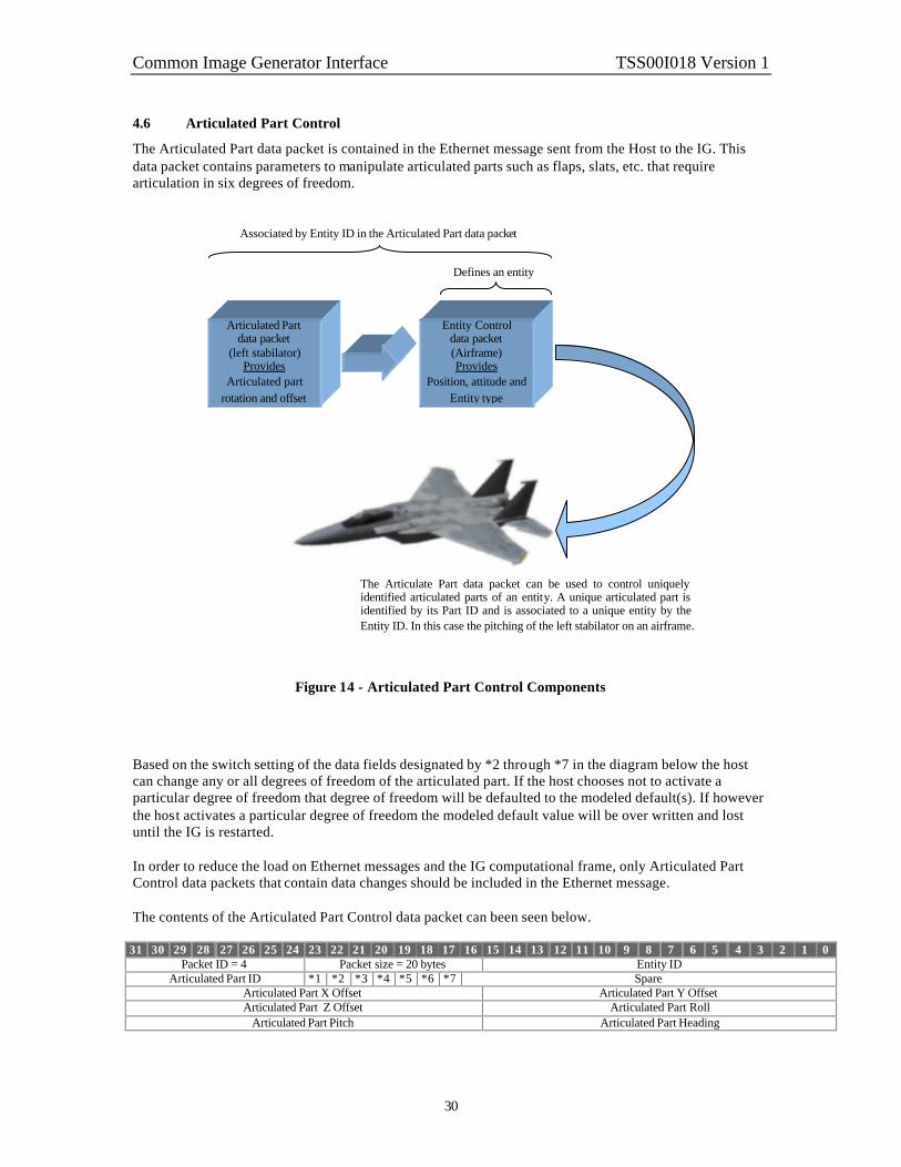
4.6 Articulated Part Control
The Articulated Part data packet is contained in the Ethernet message sent from the Host to the IG. This data packet contains parameters to manipulate articulated parts such as flaps, slats, etc. that require articulation in six degrees of freedom.
Figure 14 - Articulated Part Control Components
Based on the switch setting of the data fields designated by *2 through *7 in the diagram below the host can change any or all degrees of freedom of the articulated part. If the host chooses not to activate a particular degree of freedom that degree of freedom will be defaulted to the modeled default(s). If however the host activates a particular degree of freedom the modeled default value will be over written and lost until the IG is restarted. In order to reduce the load on Ethernet messages and the IG computational frame, only Articulated Part Control data packets that contain data changes should be included in the Ethernet message. The contents of the Articulated Part Control data packet can been seen below.
31 30 29 28 27 26 25 24 23 22 21 20 19 18 17 16 15 14 13 12 11 10 9 8 7 6 5 4 3 2 1 0 Packet ID = 4 Packet size = 20 bytes Entity ID
Articulated Part ID *1 *2 *3 *4 *5 *6 *7 Spare Articulated Part X Offset Articulated Part Y Offset Articulated Part Z Offset Articulated Part Roll
Articulated Part Pitch Articulated Part Heading
Articulated Part data packet
(left stabilator) Provides
Articulated part rotation and offset
Entity Control data packet (Airframe) Provides
Position, attitude and Entity type
Associated by Entity ID in the Articulated Part data packet
Defines an entity
The Articulate Part data packet can be used to control uniquely identified articulated parts of an entity. A unique articulated part is identified by its Part ID and is associated to a unique entity by the Entity ID. In this case the pitching of the left stabilator on an airframe.

Common Image Generator Interface TSS00I018 Version 1
31
Articulated Parts parameter definitions: Formats and Ranges Description Packet ID = 4 : unsigned char : N/A This parameter identifies this data packet as an
Articulated Part data packet. There can be multiple instances of this data packet per frame. Each instance should uniquely identify an articulated part by its Articulated Part ID. That is to say each unique articulated part can only be specified once per frame. If more than one data packet with the same Articulated Part ID is received in the same frame the last one received will be used.
Packet size : unsigned char : N/A This parameter indicates the number of bytes in this data packet.
Articulated Part ID: signed char : N/A valid values: 0 – 127 identifies a unique articulated part See the articulated part identification assignments in the applicable Database and Entity Attribute Definition Document (s). Default: N/A
This parameter indicates which articulated part is controlled with this data packet. If the specified Articulated Part ID is not a valid part of the entity specified by the Entity ID an error will be generated and no further action will be taken.
Entity ID : unsigned short : N/A valid values: 0 to 65535 Default: N/A
This parameter indicates what entity this Articulated Part data packet will be applied to. If the specified entity id contains zero the parameters in this data packet will be applied to the Ownship. If the specified entity id contains a number greater than zero the parameters in this data packet will be applied to the specified entity. If the specified Entity ID is not active an error will be generated and no further action will be taken.
*1 Articulated Part State : Boolean : N/A valid values: 0 = Inactive (removes the part from the display) 1 = Active (introduces the part into the display) Default: 1
This parameter indicates whether an articulated part is active or inactive. When an articulated part is required, this parameter should be changed to active. When the articulated part is no longer required it should be set to inactive before the data packet representing the entity is removed from the Ethernet message.
*2 Enable/Disable Articulated Part X Offset : Boolean : N/A valid values: 0 = Disable 1 = Enable Default: 0
This parameter identifies whether the Articulated Part X Offset value contained in this data packet is manipulated from the Host, i.e. Enabled, or set to the model’s default , i.e. Disabled.

Common Image Generator Interface TSS00I018 Version 1
32
*3 Enable/Disable Articulated Part Y Offset : Boolean : N/A valid values: 0 = Disable 1 = Enable Default: 0
This parameter identifies whether the Articulated Part Y Offset value contained in this data packet is manipulated from the Host, i.e. Enabled, or set to the model’s default , i.e. Disabled.
*4 Enable/Disable Articulated Part Z Offset : Boolean : N/A valid values: 0 = Disable 1 = Enable Default: 0
This parameter identifies whether the Articulated Part Z Offset value contained in this data packet is manipulated from the Host, i.e. Enabled, or set to the model’s default, i.e. Disabled.
*5 Enable/Disable Articulated Part Roll : Boolean : N/A valid values: 0 = Disable 1 = Enable Default: 0
This parameter identifies whether the Articulated Part Roll value contained in this data packet is manipulated from the Host, i.e. Enabled, or set to the model’s default , i.e. Disabled.
*6 Enable/Disable Articulated Part Pitch : Boolean : N/A valid values: 0 = Disable 1 = Enable Default: 0
This parameter identifies whether the Articulated Part Pitch value contained in this data packet is manipulated from the Host, i.e. Enabled, or set to the model’s default , i.e. Disabled.
*7 Enable/Disable Articulated Part Heading : Boolean : N/A valid values: 0 = Disable 1 = Enable Default: 0
This parameter identifies whether the Articulated Part Heading value contained in this data packet is manipulated from the Host, i.e. Enabled, or set to the model’s default, i.e. Disabled.
Articulated Part X Offset : scaled distance format (16 bit B6): meters valid values: limits of scaled distance format (16 bit B6) Default: As set in the models default Datum: Entity coordinate system, see Figure 6.
This parameter specifies the offset in the X-axis from the reference point of the sub model to a new point along the X-axis. See section 2.4.2 for a description of the data format.

Common Image Generator Interface TSS00I018 Version 1
33
Articulated Part Y Offset : scaled distance format (16 bit B6): meters valid values: limits of scaled distance format (16 bit B6) Default: As set in the models default
Datum: Entity coordinate system, see Figure 6.
This parameter specifies the offset in the Y-axis from the reference point of the sub model to a new point along the Y-axis. See section 2.4.2 for a description of the data format.
Articulated Part Z Offset : scaled distance format (16 bit B6): meters valid values: limits of scaled distance format (16 bit B6) Default: As set in the models default Datum: Entity coordinate system, see Figure 6.
This parameter specifies the offset in the Z-axis from the reference point of the sub model to a new point along the Z-axis. See section 2.4.2 for a description of the data format.
Articulated Part Roll : angle format (16 bit): degrees valid values: 0 to +180 clockwise 0 to –180 counter clockwise Default: As set in the models default Datum: see Figure 6.
This parameter specifies the roll of this part with respect to the sub model coordinate system. See section 2.4.2 for a description of the data format.
Articulated Part Pitch : angle format (16 bit): degrees valid values: 0 to +90 up 0 to –90 down Default: As set in the models default Datum: see Figure 6.
This parameter specifies the pitch of this part with respect to the sub model coordinate system. See section 2.4.2 for a description of the data format.
Articulated Part Heading : angle format (16 bit): degrees valid values: 0 to +360 clockwise Default: As set in the models default Datum: see Figure 6.
This parameter specifies the heading of this part with respect to the sub model coordinate system. See section 2.4.2 for a description of the data format.

Common Image Generator Interface TSS00I018 Version 1
34
4.7 Rate Control
The Rate Control data packet is contained in the Ethernet message sent from the Host to the IG. This data packet contains parameters that supplement the Entity Control data packet or the Articulated Part data packet as needed with rate information for the entity. An entity is normally placed using the attitude and positional data received in the Entity Control data packet. If reception of an Entity Control data packet is discontinued and a Rate Control data packet was received, the information in the Rate Control data packet will be used to continue the entity’s movement by extrapolating the entity’s position along the given vector with the given angular rates. The IG will use the placement and rate information from a former frame as basis for the extrapolation. In the event that a new Entity Control data packet is received prior to this data packet, the entity position will be updated with this information. This data packet may also be used to animate articulated parts modeled within an entity, or child parts attached to a parent model. Given proper angular rates, the IG will extrapolate these components to simulate such things as spinning propellers, rotating wheels, etc.
Figure 15 - Rate Control Components
In order to reduce the load on Ethernet messages and the IG computational frame, only Rate Control data packets that contain data changes should be included in the Ethernet message.
Rate Control data packet
Provides
Velocity vector information
Entity Control data packet
Provides
Position and Entity type
Defines entity
The Rate Control data packet can be used to move an entity along a linear path without continuous update by the host. When activated via the Entity Control data packet the object will begin at the designated position and move at the rate and direction specified by the velocity vector contained in the Rate Control data packet. This motion will continue until the Entity Control data packet disables the entity.

Common Image Generator Interface TSS00I018 Version 1
35
The contents of the Rate Control data packet can been seen below.
31 30 29 28 27 26 25 24 23 22 21 20 19 18 17 16 15 14 13 12 11 10 9 8 7 6 5 4 3 2 1 0 Packet ID = 5 Packet size = 32 bytes Entity ID
Articulated Part ID Spare Vx Component of the Velocity Vector Vy Component of the Velocity Vector Vz Component of the Velocity Vector
Roll Angular Rate Pitch Angular Rate
Heading Angular Rate Rate Control parameters para meter definitions: Formats and Ranges Description Packet ID = 5 : unsigned char : N/A This parameter identifies this data packet as the Rate
Control data packet. There can be multiple instances of this data packet per frame. Each instance should uniquely identify an entity by its Entity ID or an articulated part by an Entity ID and associated Articulated Part ID. That is to say rate information for each unique entity and/or articulated part combination can only be specified once per frame. If more than one Entity Rate data packet containing the same Entity ID or articulated part identification is received per frame the last one received will be used.
Packet size : unsigned char : N/A This parameter indicates the number of bytes in this data packet.
Entity ID : unsigned short : N/A valid values: 0 to 65535 Default: N/A
This parameter indicates what entity this data packet will be applied to. If the specified Entity ID is not active an error will be generated and no further action will be taken. If the specified entity id contains zero the parameters in this data packet will be applied to the Ownship. If the specified entity id contains a number greater than zero the parameters in this data packet will be applied to the specified entity.
Articulated Part ID: signed char : N/A valid values: -1 = Apply rates to entity only 0 – 127 identifies a unique articulated part See the articulated part identification assignments in the applicable Database and Entity Attribute Definition Document (s). Default: N/A
This parameter indicates which articulated part is controlled with this data packet. If the data is meant to control the entity only, a –1 should be placed in this field to signify an invalid articulated part. If the specified Articulated Part ID is not a valid part of the entity specified by the Entity ID an error will be generated and no further action will be taken.

Common Image Generator Interface TSS00I018 Version 1
36
Vx Component of the Velocity Vector : Float IEEE : meters per second valid values: Minimum to maximum allowed by the data format (+) forward direction (-) backward direction Default: N/A Datum: see Figure 6.
This parameter specifies the X component of the velocity vector for the entity being represented. The velocity vector is specified in the entity reference system as shown in the datum.
Vy Component of the Velocity Vector : Float IEEE : meters per second valid values: Minimum to maximum allowed by the data format (+) right wing direction (-) left wing direction Default: N/A Datum: see Figure 6.
This parameter specifies the Y component of the velocity vector for the entity being represented. The velocity vector is specified in the entity reference system as shown in the datum.
Vz Component of the Velocity Vector : Float IEEE : meters per second valid values: Minimum to maximum allowed by the data format (+) downward direction (-) upward direction Default: N/A Datum: see Figure 6.
This parameter specifies the Z component of the velocity vector for the entity being represented. The velocity vector is specified in the entity reference system as shown in the datum.
Roll Angular Rate : Float IEEE : degrees per second valid values: Minimum to maximum allowed by the data format (+) right wing down (-) left wing down Default: N/A Datum: see Figure 6.
This parameter specifies the roll angular rate for the entity being represented. The angular rate is specified in the entity reference system as shown in the datum.
Pitch Angular Rate : Float IEEE : degrees per second valid values: Minimum to maximum allowed by the data format (+) nose up direction (-) nose direction Default: N/A Datum: see Figure 6.
This parameter specifies the pitch angular rate for the entity being represented. The angular rate is specified in the entity reference system as shown in the datum.

Common Image Generator Interface TSS00I018 Version 1
37
Heading Angular Rate : Float IEEE : degrees per second valid values: Minimum to maximum allowed by the data format (+) clockwise direction (-) counterclockwise direction Default: N/A Datum: see Figure 6.
This parameter specifies the heading angular rate for the entity being represented. The angular rate is specified in the entity reference system as shown in the datum.

Common Image Generator Interface TSS00I018 Version 1
38
4.8 Environment Control
The Environment Control data packet is contained in the Ethernet message sent from the Host to the IG. The Environment Control data packet allows the Host to control the global environment parameters for a given mission scenario. The image generator provides a simulation of the position of the sun and moon based on its internal ephemeris model. The time of day is continuously incremented based on this ephemeris model. The ephemeris on/off switch turns the ephemeris model on and off. If turned off, the time of day will be set to the exact values provided in the Hour and Minute parameters of this data packet and will remain constant until the Host changes it, or until the Host enables the ephemeris model. If the Host submits time of day information while the ephemeris model is enabled, the current time of day will be changed to the values supplied by the Host, and the ephemeris model will continue to update the value thereafter. Care should be taken when sending this data packet because when the IG receives it all data parameters contained in the data packet will be updated. If the Environment values are outside the range specified an error will be returned to the Host and no further action will be taken. Sun and moon positions, moon phase, and horizon glow are computed by the image generator and do not require Host control. In order to reduce the load on Ethernet messages and the IG computational frame, only Environment data packets that contain data changes should be included in the Ethernet message. The contents of the Environment data packet can been seen below.
31 30 29 28 27 26 25 24 23 22 21 20 19 18 17 16 15 14 13 12 11 10 9 8 7 6 5 4 3 2 1 0 Packet ID = 6 Packet size = 28 bytes Hour Minute
*1 Humidity Spare Date
Air Temperature Global Visibility Wind Velocity Wind Direction
Environment Control parameter definitions: Formats and Ranges Description Packet ID = 6 : unsigned char : N/A This parameter identifies this data packet as the
Environment Control data packet. There can be only one instance of this data packet per frame. If more than one data packet is received the last one received will be used.
Packet size : unsigned char : N/A This parameter indicates the number of bytes in this data packet.
Hour : unsigned char : hours valid values: 0 – 23
Default: 0 Datum: Local time
This parameter indicates the hour of the day for the ephemeris program within the image generator.

Common Image Generator Interface TSS00I018 Version 1
39
Minute : unsigned char : minutes valid values: 0 – 59
Default: 0 Datum: Local time
This parameter indicates the minute of the hour for the ephemeris program within the image generator.
*1 Ephemeris on/off : Boolean : N/A
valid values: 0 = Static Time of Day 1 = Continuous Time of Day
Default: 1, Ephemeris program active
This parameter controls whether a continuous time of day or static time of day is used for a mission. If set to continuous, the image generator will update the time of day.
Humidity : unsigned 7 bit field : percent valid values: 0 to 100 101 to 127 are invalid Default: N/A
This parameter indicates the global humidity of the environment.
Date : integer : MMDDYYYY valid values: MMDDYYYY = (month number * 1000000) + (day number * 10000) + year number
Default: N/A
This parameter indicates the desired date for use by the ephemeris program within the image generator.
Air Temperature : Float IEEE: degrees Celsius valid values: Minimum to maximum allowed by the data format Default: N/A Datum: 0o C
This parameter indicates the global temperature of the environment.
Global Visibility : Float IEEE: meters valid values: 0 to maximum allowed by the data format
Default: 0
This parameter indicates the global visibility.
Wind Velocity : Float IEEE: meters per second valid values: 0 to maximum allowed by the data format
Default: 0
This parameter indicates the global velocity of the wind.

Common Image Generator Interface TSS00I018 Version 1
40
Wind Direction : Float IEEE: degrees valid values: 0 to +360 clockwise Default: N/A Datum: True North
This parameter indicates global direction of the wind.

Common Image Generator Interface TSS00I018 Version 1
41
4.9 Weather Control
The Weather Control data packet is contained in the Ethernet message sent from the Host to the IG. This data packet is used to control and/or override default local or layered weather phenomena. The parameters within this data packet allow for the descriptions of haze, ground fog, rain, cloud layers, etc. When the data packet is used to represent ground fog, the Host is responsible for maintaining the relationship between visibility and Runway Visual Range via the Runway Visibility Range parameter of this data packet. Particular weather phenomena may be assigned to an entity. Hence, position/orientation controls for weather are controlled via the Entity Control data packet for these types. In order to reduce the load on Ethernet messages and the IG computational frame, only Weather Control data packets that contain data changes should be included in the Ethernet message. The contents of the Weather Control data packet can been seen below.
31 30 29 28 27 26 25 24 23 22 21 20 19 18 17 16 15 14 13 12 11 10 9 8 7 6 5 4 3 2 1 0 Packet ID = 7 Packet size = 44 bytes Entity ID
*1 *2 *3 *4 Spare Phenomena Type Air Temperature
Opacity/Runway Visibility Range Scud
Coverage Elevation Thickness
Transition Band Winds Aloft Velocity Winds Aloft Direction
Weather Control parameter definitions: Formats and Ranges Description Packet ID = 7 : unsigned char : N/A This parameter identifies this data packet as the Weather
Control data packet. There can be multiple instances of this data packet per frame. Each instance should uniquely identify weather phenomena via the phenomena parameter in this data packet.
Packet size : unsigned char : N/A This parameter indicates the number of bytes in this data packet.
Entity ID : unsigned short : N/A valid values: 0 to 65535 Default: N/A
This parameter indicates which Entity ID, i.e. Entity Control data packet this weather model is assigned to. This field may be valid only for particular local weather phenomena (e.g. thunderstorms, fronts, and sandstorms). This parameter is only used when the Phenomena Type of this data packet is zero.
*1 Weather State : Boolean : N/A valid values: 0 = Disable 1 = Enable
Default: 0
This parameter indicates whether the phenomena specified by this data packet is visible (Enable) or not (Disable).

Common Image Generator Interface TSS00I018 Version 1
42
*2 Scud : Boolean : N/A valid values: 0 = Disable 1 = Enable
Default: 0
This parameter indicates whether there will be scud effects applied to the phenomena specified by this data packet. If this parameter is applied to the ground fog layer it will cause a patchy fog effect.
*3 Random Winds Aloft: Boolean : N/A valid values: 0 = Disable 1 = Enable
Default: 0
This parameter indicates whether a random frequency and duration should be applied to the Winds Aloft value. This is meant to provide for gusting winds. Wind Aloft will enable phenomena drift contrasting with the global winds parameters defined in the Environment Control data packet.
*4 Severity : 3 bit field : N/A valid values: 0 – 5 Least to most severe
Default: N/A
This parameter indicates the severity of particular weather phenomena. This parameter can be used to control such things as thunderstorm severity or sea state.
Phenomena Type : unsigned short: N/A valid values: 0 = Use Entity ID 1 = Cloud Layer 1 2 = Cloud Layer 2 3 = Ground Fog 4 = Rain 5 = Snow 6 = Sand 7 to 65535 defined by the IG Default: N/A
This parameter indicates the type of weather described by this data packet. Values zero through seven are provided to establish a common numbering scheme for standard layered weather.
Air Temperature : Float IEEE: degrees Celsius valid values: Minimum to maximum allowed by the data format Default: N/A Datum: 0o C
This parameter indicates the local temperature inside the weather phenomena.

Common Image Generator Interface TSS00I018 Version 1
43
Opacity : Float IEEE: Percent valid values: 0 to 100%
Default: 0 ------------------ Or ------------------ Runway Visibility Range : Float IEEE: meters valid values: 0 to < global visibility
Default: 0
This parameter indicates the opacity of weather phenomena. One hundred percent opaque equals no visibility through the phenomena. This control is meant to provide a transmissive or density effect for the weather (e.g. wispy clouds, rain severity, snow severity) This parameter indicates the distance from the eye point to a point where the scene is completely fogged. This parameter is valid only when the Phenomena Type is set to ground fog.
Scud : Float IEEE: Percent valid values: 0 to 100%
Default: N/A
This parameter indicates the frequency of the scud effect. 0% being no scud affect to 100% being a solid effect. If this parameter is applied to the ground fog layer it will cause a patchy fog effect.
Coverage : Float IEEE: Percent valid values: 0 to 100%
Default: N/A
This parameter indicates the amount of arial coverage a particular phenomenon has over the specified global visibility range given in the Environment Control data packet. (e.g 100% for Cloud Layer equals a solid cloud layer).
Elevation : Float IEEE: meters valid values: 0 to maximum allowed by the data format
Default: 0 Datum: MSL
This parameter indicates the base (bottom) altitude of the weather phenomena.
Thickness : Float IEEE: meters valid values: 0 to maximum allowed by the data format
Default: 0 Datum: Elevation upward as defined in this data packet.
This parameter indicates the vertical thickness of the weather phenomena. When applied to clouds or fog, elevation plus thickness equals the top of the layer.
Transition Band : Float IEEE: meters valid values: 0 to maximum allowed by the data format
Default: N/A
Datum: As defined in this data packet, Elevation downward for the bottom and Elevation plus Thickness upward for the top.
This parameter indicates a vertical transition band both above and below (if applicable) a phenomena. While within this band, visibility transitions from the specified opacity to the global visibility value given in the Environment Control data packet.

Common Image Generator Interface TSS00I018 Version 1
44
Winds Aloft Velocity : Float IEEE: meters per second valid values: 0 to maximum allowed by the data format
Default: 0
This parameter indicates the local velocity of the wind applied to the phenomena specified by this data packet. To disable Winds Aloft, this parameter should be set to zero.
Winds Aloft Direction : Float IEEE: degrees valid values: 0 to +360 clockwise Default: N/A Datum: True North
This parameter indicates local direction of the wind applied to the phenomena specified by this data packet.

Common Image Generator Interface TSS00I018 Version 1
45
4.10 View Control
The View Control data packet is contained in the Ethernet message sent from the Host to the IG. It is used to attach a view to an entity and to define the distance between a view position/orientation and an entity’s reference point. This concept can be used to specify view offsets such as pilot eye, weapon/sensor viewpoints, and stealth views. It should be noted that the number of views might be limited by the IG configuration. It is also assumed that the characteristics of a view found in the View Definition data packet of this interface are defaulted within the IG or must be specified by the View Definition data packet in section 4.14. The order of operation to move and rotate the view must be such that the view is translated with respect to the entity’s body axis by applying the X, Y and Z offset values supplied in this data packet and then rotated about the new position using the heading, pitch and roll supplied in this data packet. This data packet should be supplied to the IG at mis sion initialization and then again any time it is required to move a view position relative to an entity’s reference point.
Figure 16 – View Point Offset and Orientation from Entity Reference
+X
+Y
+Z
+X
+Y
+Z
+ Roll
+ Heading
+ Pitch
View offset
Entity reference

Common Image Generator Interface TSS00I018 Version 1
46
The contents of the View Control data packet can be seen below.
31 30 29 28 27 26 25 24 23 22 21 20 19 18 17 16 15 14 13 12 11 10 9 8 7 6 5 4 3 2 1 0 Packet ID = 8 Packet size = 32 bytes Entity ID
View ID *1 Spare X Offset Y Offset Z Offset
View Roll View Pitch
View Heading View Control parameter definitions: Formats and Ranges Description Packet ID = 8 : unsigned char : N/A This parameter identifies this data packet as a View
Control data packet. There can be multiple instances of this data packet per frame. Each instance should uniquely identify a view via the View ID parameter in this data packet.
Packet size : unsigned char : N/A This parameter indicates the number of bytes in this data packet.
Entity ID : unsigned short : N/A valid values: 0 to 65535 Default: 0
This parameter indicates which entity this view should be attached to.
View ID: 5 bit field: N/A valid values: 0 – 31 View ID Default = 0
This parameter specifies what view position is associated with a particular set of offsets specified by this data packet. If the Host requests an view that has not be configured on the IG, an error will be generated and no further action will be taken
*1 View Group Select: 3 bit field: N/A valid values: 0 = invalid
1 – 7 Group select
Default = 0
This parameter specifies the view group to be controlled by the offsets specified by this data packet. When this parameter is specified to be a value of 1 to 7 The associated data will position a view group as defined in the View Definition data packet. When this parameter is 0, the field is disregarded, and position control is performed on an individual view. If the Host requests a group that has not be defined by the View Definition data packet, or pre-configured on the IG, an error will be generated and no further action will be taken.

Common Image Generator Interface TSS00I018 Version 1
47
X Offset: Float IEEE : meters valid values: Minimum to maximum allowed by the data format Default: 0 Datum: Entity coordinate system, see Figure 6.
This parameter is used to define the X component of the view offset vector i.e. the distance forward and backward along the entity’s coordinate system, see Figure 16.
Y Offset: Float IEEE : meters valid values: Minimum to maximum allowed by the data format Default: 0 Datum: Entity coordinate system, see Figure 6.
This parameter is used to define the X component of the view offset vector i.e. the distance forward and backward along the entity’s coordinate system, see Figure 16.
Z Offset: Float IEEE : meters valid values: Minimum to maximum allowed by the data format Default: 0 Datum: Entity coordinate system, see Figure 6.
This parameter is used to define the X component of the view offset vector i.e. the distance forward and backward along the entity’s coordinate system, see Figure 16.
View Roll: Float IEEE: degrees valid values: 0 to +180 clockwise 0 to –180 counter clockwise Default: As set in the models default Datum: Entity coordinate system, see Figure 6.
This parameter specifies the roll of this view with respect to the position the view has been moved to via the view offset vector, Figure 16.
View Pitch: Float IEEE: degrees valid values: 0 to +90 up 0 to –90 down Default: As set in the models default Datum: Entity coordinate system, see Figure 6.
This parameter specifies the pitch of this view with respect to the position the view has been moved to via the view offset vector, Figure 16.
View Heading: Float IEEE: degrees valid values: 0 to +360 clockwise Default: As set in the models default Datum: Entity coordinate system, see Figure 6.
This parameter specifies the heading of this view with respect to the position the view has been moved to via the view offset vector, Figure 16.

Common Image Generator Interface TSS00I018 Version 1
48
4.11 Sensor Control
The Sensor Control data packet is contained in the Ethernet message sent from the Host to the IG. This data packet in conjunction with the View Control, View Definition, Component Control and LOS Range Request data packets control and describe the abilities of a sensor-based weapon system. This Sensor Control data packet will provide sensor mode of operation and display behavior. This data packet is associated to a particular View Control data packet via the View ID parameter of this data packet. This will allow for positioning and orienting of a sensor with respect to an entity. Field-of-view characteristics may be controlled using a View Definition data packet, which is also associated using the View ID parameter of that data packet. Discrete sensor attributes are controlled using Component Control data packet(s). These data packet(s) are also associated to a particular view via the View ID parameter of the data packet(s). The Line-Of-Sight Point Request data packet is used to provoke a Line-Of-Sight Point Response data packet containing the intersection point on the database along the Line-Of-Sight based on the sensor position and orientation specified in the View Control data packet.
Figure 17 – Sensor Definition Components
Associated by View ID parameter in each data packet
View Control data packet
Provides
Position and orientation
Defines sensor view
Component Control
data packet
Provides Discrete sensor
attributes
View Definition data packet
Provides
FOV characteristics
Sensor Control data packet
Provides
Sensor mode Display control
LOS Range Request data packet
Provokes
LOS Response
LOS Response data packet
Provides
Object intersection position
This data packet contains a LOS ID that uniquely identifies a sensor request. When the IG returns this LOS ID in the corresponding LOS Response data packet it will be used to determine latency so that the original sensor position can be retrieved and a range can be determined.

Common Image Generator Interface TSS00I018 Version 1
49
When a Sensor Control data packet is sent from the Host, associated Component Control and LOS Range Request data packets may also be sent. It will be useful to the Host to know which series of data packets are associated with the same request. Even though the LOS Range Request has a unique LOS ID it may be useful to have the Host internally associate these packets together via the Sensor ID of the Sensor Control data packet. To match up Sensor Control and other associated data packets from the host with responses from the IG, the “Sensor ID” parameter is used. The same number that is placed in this parameter will be returned in the “Sensor ID” parameter of the corresponding Sensor Response data packet described in section 4.23 to uniquely identify the response. The “Sensor ID” value should be manipulated in such a way as to not duplicate the value in a reasonable amount of time, say one second. This will prevent similarly identified requests from being lost by the IG. There is no restriction on the number of Sensor Control data packets that can be make in a single frame. The user should be aware however that the response time of the IG might be degraded under conditions that overload the IG Sensor computation mechanism. The contents of the Sensor Control data packet can be seen below.
31 30 29 28 27 26 25 24 23 22 21 20 19 18 17 16 15 14 13 12 11 10 9 8 7 6 5 4 3 2 1 0 Packet ID = 9 Packet size = 20 bytes View ID *1 *2 *3 Sensor ID
*4 *5 *6 Spare Gain Level
AC Coupling Noise
Sensor Control parameter definitions: Formats and Ranges Description Packet ID = 9 : unsigned char : N/A This parameter identifies this data packet as a Sensor
Control data packet. There can be multiple instances of this data packet per frame. Each instance should uniquely identify a sensor by its view number specified in View ID field. That is to say each unique sensor can only be specified once per frame. If more than one Sensor Control data packet containing the same view number is received per frame the last one received will be used.
Packet size : unsigned char : N/A This parameter indicates the number of bytes in this data packet.
View ID: 5 bit field: N/A valid values: 0 = Not Used 1 – 31 Weapon Sensor view point Default = 0
This parameter dictates which view the corresponding sensor is assigned to regardless of view group. The offsets associated with a view are specified via the View Control data packet.
*1 Sensor on / off : Boolean : N/A valid values: 0 = off 1 = on Default = 0
This parameter indicates whether this Sensor is turned on or off.

Common Image Generator Interface TSS00I018 Version 1
50
*2 Polarity : Boolean : N/A valid values: 0 = White 1 = Black Default = 0
This parameter indicates whether this Sensor is showing white hot or black hot.
*3 line-by-line drop-out : Boolean : N/A valid value: 0 = off 1 = on Default = 0
This parameter indicates whether the line-by-line drop-out feature is either on or off.
Sensor ID : unsigned char : N/A valid values: 0 to 255 Default: 0
This parameter is used to identify the Sensor Control so that when the answer to the Sensor Control input is returned it can be identified by the host. This is done via the Sensor ID parameter of the Sensor Response data packet.
*4 Track mode on/off : 4 bit field: N/A valid values: 0 = off 1 = Force correlate 2 = Scene 3 = Target 4 = Ship 4 – 15 invalid Default = 0
This parameter indicates whether the scene track or target track mode is enabled. If an invalid value is received an error will be generated and not further action will be taken.
*5 Automatic Gain: Boolean: N/A valid values: 0 = off 1 = on Default = 0
This parameter causes the Weapons Sensor to automatically adjust the gain value to optimize the brightness and contrast of the sensor display when enabled.
*6 Track white or black : Boolean: N/A valid values: 0 = white 1 = black Default = 0
This parameter causes the Weapons Sensor to track either white or black.

Common Image Generator Interface TSS00I018 Version 1
51
Gain : Float IEEE : N/A Valid values:
0.0 to 100.0 0.1
Default = N/A
This parameter indicates the gain value for the weapon sensor option. The adjustment of both Gain and Level in this data packet are used together to improve the contrast of the target imagery.
Level : Float IEEE : N/A Valid values:
0.0 to 1.0
Default = N/A
This parameter indicates the level value for the weapon sensor option. The adjustment of both Level and Gain in this data packet are used together to improve the contrast of the target imagery.
AC Coupling : Float IEEE : N/A Valid values:
0.0 to 1.0
Default = N/A
This parameter indicates the AC Coupling decay rate for the weapon sensor option. This feature is only available when the IG is equipped with enhanced Weapons Sensor effects.
Noise : Float IEEE : N/A Valid values:
0.0 to 1.0
Default = 0.0 (noise off)
This parameter indicates the detector-noise gain for the weapon sensor option.

Common Image Generator Interface TSS00I018 Version 1
52
4.12 Trajectory Definition
The Trajectory Definition data packet is contained in the Ethernet message sent from the Host to the IG. This data packet is used in conjunction with the Entity Control data packet, the Special Effects Definition data packet and the Rate data packet to define aspects of an object’s trajectory. The Entity Control data packet will provide the initial position for the associated entity plus other applicable parameters; the Special Effects Definition data packet will provide effects duration, burst count, separation, color, etc.; the Rate data packet will provide the initial velocity components.
Figure 18 – Trajectory Definition Components
Rate Control data packet
Provides
Velocity vector information
The Retardation rate should be applied to each velocity vector component proportionally until the component velocity reaches zero, at which point the object is in free fall.
During free fall the object should continue to accelerate based on the Acceleration factor until it reaches the specified Terminal velocity.
Associated by Entity ID in each data packet
Entity Control data packet
Provides
Position, attitude and Entity type
Defines parent entity
Special Effects Definition data packet
Provides
Burst information
Trajectory Definition data packet
Provides
Acceleration, Velocity, and Offsets
The Trajectory Definition data packet provides vector component offsets to allow the offset of the origin of a trajectory from its associated entity’s reference point, for example a cannon muzzle.

Common Image Generator Interface TSS00I018 Version 1
53
The contents of the Trajectory Definition data packet can be seen below.
31 30 29 28 27 26 25 24 23 22 21 20 19 18 17 16 15 14 13 12 11 10 9 8 7 6 5 4 3 2 1 0 Packet ID = 21 Packet size = 28 bytes Entity ID
Acceleration factor Retardation rate
Terminal velocity X offset Y offset Z offset
Trajectory Definition parameter definitions: Formats and Ranges Description Packet ID = 21 : unsigned char : N/A This parameter identifies this data packet as the
Trajectory Definition data packet. There can be multiple instances of this data packet per frame. Each instance should uniquely identify a Trajectory Definition by the Entity ID. That is to say each unique Trajectory can only be specified once per frame. If more than one data packet with the same Entity ID is received in the same frame the last one received will be used.
Packet size : unsigned char : N/A This parameter indicates the number of bytes in this data packet.
Entity ID : unsigned short : N/A valid values: 0 to 65535 Default: N/A
This parameter indicates which entity is being influenced by this trajectory behavior. The specified Entity ID must have been previously defined. If this data packet is sent without a previously defined Entity ID either earlier in the same Ethernet message or in an earlier Ethernet message, an error will be generated and this data packet will be ignored.
Acceleration factor : Float IEEE: meters/seconds2
valid values: 0 to maximum allowed by the data format Default: N/A
This parameter indicates the acceleration factor that will be applied to the Vz component of the velocity vector over time.
Retardation rate : Float IEEE: meters/second valid values: 0 to maximum allowed by the data format Default: N/A
This parameter indicates what retardation factor will be applied to the object’s motion. This factor will be used to proportionally reduce the Vx, Vy and Vz components of the velocity vector over time until they reach zero to approximate frictional forces on the object.
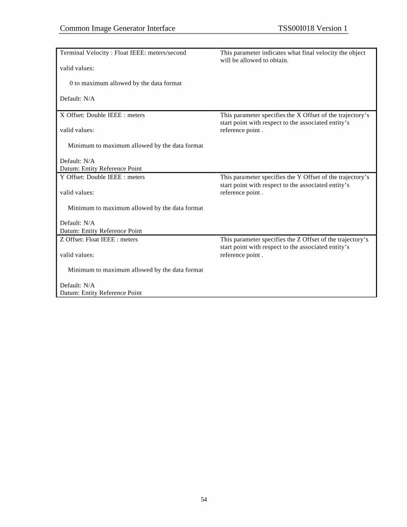
Common Image Generator Interface TSS00I018 Version 1
54
Terminal Velocity : Float IEEE: meters/second valid values: 0 to maximum allowed by the data format Default: N/A
This parameter indicates what final velocity the object will be allowed to obtain.
X Offset: Double IEEE : meters valid values: Minimum to maximum allowed by the data format Default: N/A Datum: Entity Reference Point
This parameter specifies the X Offset of the trajectory’s start point with respect to the associated entity’s reference point .
Y Offset: Double IEEE : meters valid values: Minimum to maximum allowed by the data format Default: N/A Datum: Entity Reference Point
This parameter specifies the Y Offset of the trajectory’s start point with respect to the associated entity’s reference point .
Z Offset: Float IEEE : meters valid values: Minimum to maximum allowed by the data format Default: N/A Datum: Entity Reference Point
This parameter specifies the Z Offset of the trajectory’s start point with respect to the associated entity’s reference point .

Common Image Generator Interface TSS00I018 Version 1
55
4.13 Special effect Definition
The Special Effect Definition data packet is contained in the Ethernet message sent from the Host to the IG. This data packet is used in conjunction with the Entity Control data packet to override the default-modeled parameters within an effect. The effect must be loaded via an Entity Control data packet either earlier in the same Ethernet message or in an earlier Ethernet message before the Special Effects Definition can be applied. In order to reduce the load on Ethernet messages and the IG computational frame, only Special Effect Definition data packets that contain data changes should be included in the Ethernet message. The contents of the Special Effect Definition data packet can been seen below.
31 30 29 28 27 26 25 24 23 22 21 20 19 18 17 16 15 14 13 12 11 10 9 8 7 6 5 4 3 2 1 0 Packet ID = 22 Packet size = 32 bytes Entity ID
*1 *2 Spare Red color value Green color value Blue color value X Scale Y Scale Z Scale Time Scale Spare Burst Count
Separation Burst Rate Duration
Special Effect Definition parameter definitions: Formats and Ranges Description Packet ID = 22 : unsigned char : N/A This parameter identifies this data packet as the Special
Effect Definition data packet. There can be multiple instances of this data packet per frame. Each instance should uniquely identify a Special Effect Definition by the Entity ID. That is to say each unique effect can only be specified once per frame. If more than one data packet with the same Entity ID is received in the same frame the last one received will be used.
Packet size : unsigned char : N/A This parameter indicates the number of bytes in this data packet.
Entity ID : unsigned short : N/A valid values: 0 to 65535 Default: N/A
This parameter indicates which effect is being uniquely modified. An effect must be previously assigned to an Entity ID. If this data packet is sent without a previously defined Entity ID either earlier in the same Ethernet message or in an earlier Ethernet message, an error will be generated and this data packet will be ignored.
*1 Sequence Direction : Boolean : N/A valid values: 0 = Forward 1 = Backward Default: 0
This parameter indicates whether the effect animation sequence should be sequence from start to end or end to start.

Common Image Generator Interface TSS00I018 Version 1
56
*2 Color switch : Boolean : N/A valid values: 0 = Off 1 = On Default: 0
This parameter indicates whether the Red, Green, and Blue color values specified in this data packet will be applied to the special effect.
Red color value : unsigned char : N/A valid values: 0-255 Default: N/A
This parameter indicates what value of the red color the effect will be given. If the color switch indicates off this parameter will be ignored and the color of the effect will be as the database developer built it.
Green color value : unsigned char : N/A valid values: 0-255 Default: N/A
This parameter indicates what value of the green color the effect will be given. If the default color switch indicates on this parameter will be ignored and the color of the effect will be as the database developer built it.
Blue color value : unsigned char : N/A valid values: 0-255 Default: N/A
This parameter indicates what value of the blue color the effect will be given. If the default color switch indicates on this parameter will be ignored and the color of the effect will be as the database developer built it.
X Scale : scaled distance format (16 bit B6): meters valid values: limits of scaled distance format (16 bit B6) Default: 1.0 Datum: Entity coordinate system, see Figure 6.
This parameter specifies a scale factor to apply to the effect dimensions along the longitudinal axis.
Y Scale : scaled distance format (16 bit B6): meters valid values: limits of scaled distance format (16 bit B6) Default: 1.0
Datum: Entity coordinate system, see Figure 6.
This parameter specifies a scale factor to apply to the effect dimensions along the lateral axis.
Z Scale : scaled distance format (16 bit B6): meters valid values: limits of scaled distance format (16 bit B6) Default: 1.0 Datum: Entity coordinate system, see Figure 6.
This parameter specifies a scale factor to apply to the effect dimensions along the height axis.

Common Image Generator Interface TSS00I018 Version 1
57
Time Scale : scaled distance format (16 bit B6): N/A valid values: limits of scaled distance format (16 bit B6) Default: 1.0
This parameter specifies a scale factor to apply to the time extent of an animation.
Burst Count : unsigned short : number of repetitions of an effect valid values: 0 = ignore 1 to Maximum allowed by data format Default: N/A
This parameter indicates how many effects are in a single burst. This allows display of a certain number of repetitions of an effect using a single data packet. This feature may be useful for rendering gun flashes, for example; the Host could specify that 15 rounds would be fired from a particular weapon where each firing would be represented by a gun flash effect. Rather than submit 15 data packets to control those flashes, a single data packet with this field set to 15 would achieve the same result. The Host may control the frequency of the bursts by setting the Burst Rate field of this data packet to an appropriate value.
Separation : float IEEE: meters valid values: 0 = ignore >0 to Maximum allowed by data format Default: N/A
This parameter indicates the distance between effects within a burst when the Burst Count parameter of this data packet is greater than zero.
Burst Rate : float IEEE: seconds valid values: 0 = ignore >0 to Maximum allowed by data format Default: N/A
This parameter indicates the time between bursts when the Burst Count parameter of this data packet is greater than zero.
Duration : float IEEE : second valid values: -1 = always on 0 = using default >0 to Maximum allowed by data format Default: 0.
This parameter indicates how long an effect or sequence of bursts will be active. If an effect has a non-negative duration the effect will automatically be disabled after the duration elapses.

Common Image Generator Interface TSS00I018 Version 1
58
4.14 View Definition
The View Definition data packet is contained in the Ethernet message sent from the Host to the IG. It is used to define the characteristics of a view and/or override the IG default configuration.
Figure 19 - View Definition Nomenclature
FOV left size
(degrees)
FOV bottom size
(degrees)
+X
+Y
+Z FOV near is the distance from the View reference
point to this plane
FOV right size
(degrees)
FOV top size
(degrees)
View reference
point
FOV far is the distance from the View reference
point to this plane
View Definition data packet
Provides
View size and depth
View Control data packet
Provides
View position and orientation
Associated by View ID in the Component Control data packet
Defines a view
FOV sizes may be specified to create asymmetric views.

Common Image Generator Interface TSS00I018 Version 1
59
Indicating none in the View Group Assign parameter allows for individual definition of a view. In this case parameters within this data packet will be applied to the specified View ID. Figure 20 shows three individual views that would have been defined using three instances of the View Definition data packet. Each instance would have specifying a unique View ID, one through three. In all of these instances the View Group Assign would have indicated none.
Figure 20 - Individual definitions for three views
Individual views may be grouped together by using the view group feature of this data packet. In this way several views can be moved in unison through the use of the View Control data packet. To do this two or more View Definition data packets will be used to assign individual views to the same view group via the View Group Assign and View ID parameters of this data packet. In this case only the View Group Assign and View ID parameters within this data packet are used. If, for example the three individual views shown in Figure 20 were group together in this fashion the result would be as demonstrated in Figure 21.
Figure 21- A grouping of three individual views
A group of views can also be separated if required. To do this the View Definition data packet can be submitted, as an individual view would be. For instance to separate view three the data packet would specify a View ID of three with a View Group Assign of none as seen in Figure 22.
View 1 View 2
View 3
View 1 View 2
View 3

Common Image Generator Interface TSS00I018 Version 1
60
Figure 22 - View three separated from a view group
In order to reduce the load on Ethernet messages and the IG computational frame, only View Definition data packets that contain data changes should be included in the Ethernet message. The contents of the View Definition data packet can be seen below.
31 30 29 28 27 26 25 24 23 22 21 20 19 18 17 16 15 14 13 12 11 10 9 8 7 6 5 4 3 2 1 0 Packet ID = 23 Packet size = 32 bytes View ID *1 *2 *3 *4
*5 Spare Field of View Near Field of View Far Field of View Left
Field of View Right Field of View Top
Field of View Bottom
View Definition parameter definitions: Formats and Ranges Description Packet ID = 23 : unsigned char : N/A This parameter identifies this data packet as a View
Definition data packet. There can be multiple instances of this data packet per frame. Each instance should uniquely identify a View Definition via a View Group Assignment and/or a View ID. That is to say each unique View Definition can only be specified once per frame. If more than one data packet for a given View definition is received in the same frame the last one received will be used.
Packet size : unsigned char : N/A This parameter indicates the number of bytes in this data packet.
View ID: 5 bit field: N/A valid values: 0 – 31 View ID Default = 0
This parameter specifies what view position is associated with a particular set of offsets specified by this data packet. If the Host requests an view that has not be configured on the IG, an error will be generated and no further action will be taken
View 3 View 1 View 2

Common Image Generator Interface TSS00I018 Version 1
61
*1 View Group Assign: 3 bit field: N/A valid values: 0 = none
1 – 7 Group select
Default = 0
This parameter specifies a View ID to be added to the specified view group. Only one view can be added to a view group per data packet. Therefore two or more View Definition data packets will need to be used to define a group of views. When this parameter is 0, the field is disregarded, and definition of an individual view is performed in the view specified by the View ID parameter of this data packet.
*2 View Type: 3 bit field: N/A valid values: 0 – 7 Default = 0
This parameter specifies what type of view should be supplied by the view. The integration engineer should consult the image generator configuration to obtain what types of views are available and what their View Type assignments should be.
*3 Pixel Replication: 3 bit field: N/A valid values:
0 = No Replicate 1 = 1x2 Pixel Replicate 2 = 2x1 Pixel Replicate 3 = 2x2 Pixel Replicate 4 = TBD 5 = TBD 6 = TBD 7 = TBD
Default = 0
This parameter specifies what pixel replication function should be applied to the view. This function is typically used in particular sensor applications to perform electronic zoom (pixel and line doubling function).
*4 View Mirror: 2 bit field: N/A valid values:
0 = None 1 = Horizontal 2 = Vertical 3 = Horizontal and Vertical
Default = 0
This parameter specifies what mirroring functions should be applied to the view. This function is typically used to replicate the view of a mirrored surface used in display systems or rear view mirrors.
*5 Tracker Assign: 1 bit field: N/A valid values:
0 = Not Assigned 1 = Assigned
Default = 0
This parameter specifies whether the view should be attached to the input controls from an external-tracking device.

Common Image Generator Interface TSS00I018 Version 1
62
Field of View Near: Float IEEE : meters valid values: >0 to maximum allowed by the data format Default : 1.0 Datum: View Reference Point, see Figure 19.
This parameter is used to define the near clipping plane for the view. It is a positive number greater that 0. Any object inside of this distance will be clipped from the view. It should be noted that 0 is not a valid value
Field of View Far: Float IEEE : meters valid values: >Field of View Near to maximum allowed by the data format Default: N/A Datum: View Reference Point, see Figure 19.
This parameter is used to define the far clipping plane for the view. Any object outside of this distance will be clipped from the view. It is a positive number greater than the value used for the Field of View Near value. It should be noted that 0 is not a valid value.
Field of View Left : Float IEEE : degrees valid values: -179.9 to 179.9 Default: N/A Datum: View Reference Point, see Figure 19.
This parameter is used to define the size of the left side of the field of view for the view. This value should always be less than the Field of View Right value specified in this data packet. If this condition is not satisfied, an error will be generated and no further action will be taken.
Field of View Right: Float IEEE : degrees valid values: -179.9 to 179.9 Default: N/A Datum: View Reference Point, see Figure 19.
This parameter is used to define the size of the right side of the field of view for the view. This value should always be greater than the Field of View Left value specified in this data packet. If this condition is not satisfied, an error will be generated and no further action will be taken.
Field of View Top: Float IEEE : degrees valid values: -179.9 to 179.9 Default: N/A Datum: View Reference Point, see Figure 19.
This parameter is used to define the size of the top side of the field of view for the view. This value should always be greater than the Field of View Bottom value specified in this data packet. If this condition is not satisfied, an error will be generated and no further action will be taken.
Field of View Bottom: Float IEEE : degrees valid values: -179.9 to 179.9 Default: N/A Datum: View Reference Point, see Figure 19.
This parameter is used to define the size of the bottom side of the field of view for the view. This value should always be less than the Field of View Top value specified in this data packet. If this condition is not satisfied, an error will be generated and no further action will be taken.

Common Image Generator Interface TSS00I018 Version 1
63
4.15 Collision Detection Definition
The Collision Detection Definition data packet is contained in the Ethernet message sent from the Host to the IG. It is used to define a vector that collision testing will be performed along. This vector is referenced to a particular entity specified by the Entity ID. All enabled vectors will be tested for intersection against surfaces other than surfaces associated with the given entity. In addition, a “MATERIAL MASK” field is provided that is used to eliminate particular materials from a reported collision. This provides the ability to filter certain effects within the environment such as clouds, storms, dust, etc. To match collision vector definitions with responses from the IG, the “VECTOR ID” parameter is used. The same number that is placed in this parameter will be returned in the “VECTOR ID” parameter of the corresponding Collision Detection Response data packet as described in section 4.22 to uniquely identify the response. Each vector must be assigned a unique ID per entity. Thus, a vector ID of zero, one, two… can be assigned to every entity if desired. The contents of the Collision Detection Definition data packet can be seen below.
31 30 29 28 27 26 25 24 23 22 21 20 19 18 17 16 15 14 13 12 11 10 9 8 7 6 5 4 3 2 1 0 Packet ID = 24 Packet size = 24 bytes Entity ID
*1 Vector ID Spare Material Mask
Vector X Start Vector Y Start Vector Z Start Vector X End Vector Y End Vector Z End
Collision Detection Definition parameter definitions: Formats and Ranges Description Packet ID = 24 : unsigned char : N/A This parameter identifies this data packet as the Collision
Detection Definition data packet. There can be multiple instances of this data packet per frame. Each instance should uniquely identify an Entity ID and Vector ID. That is to say each unique collision detection definition can only be specified once per frame. If more than one data packet with the same Entity ID and Vector ID is received in the same frame the last one received will be used.
Packet size : unsigned char : N/A This parameter indicates the number of bytes in this data packet.
*1 Enable/Disable : Boolean : N/A valid values: 0 = Disabled 1 = Enabled Default: 0
This parameter indicates whether the defined vector is enabled for collision testing or not.
Vector ID : 7 bit field : N/A valid values: 0 to 127 Default: N/A
This parameter indicates which vector is being uniquely defined for a given entity. The range of Vector ID 0 through 127 can be reused per entity.

Common Image Generator Interface TSS00I018 Version 1
64
Entity ID : unsigned short : N/A valid values: 0 to 65535 Default: N/A
This parameter indicates which entity this collision detection definition is assigned. An entity must be previously assigned to an Entity ID. If this data packet is sent without a previously defined Entity ID either earlier in the same Ethernet message or in an earlier Ethernet message, an error will be generated and this data packet will be ignored.
Material Mask : hexadecimal : N/A valid values: 0x0000 to 0xFFFF Default: 0xFFFF
This parameter indicates which material values assigned to a polygon surface, which is intersected by this vector, is to be ignored by the collision detection process.
Vector X Start : scaled distance format (16 bit B6): meters valid values: limits of scaled distance format (16 bit B6) Default: N/A Datum: Entity coordinate system, see Figure 6.
This parameter specifies the starting point of the collision vector in the X-axis. See section 2.4.2 for a description of the data format.
Vector Y Start : scaled distance format (16 bit B6): meters valid values: limits of scaled distance format (16 bit B6) Default: N/A Datum: Entity coordinate system, see Figure 6.
This parameter specifies the starting point of the collision vector in the Y-axis. See section 2.4.2 for a description of the data format.
Vector Z Start : scaled distance format (16 bit B6): meters valid values: limits of scaled distance format (16 bit B6) Default: N/A Datum: Entity coordinate system, see Figure 6.
This parameter specifies the starting point of the collision vector in the Z-axis. See section 2.4.2 for a description of the data format.
Vector X End : scaled distance format (16 bit B6): meters valid values: limits of scaled distance format (16 bit B6) Default: N/A Datum: Entity coordinate system, see Figure 6.
This parameter specifies the ending point of the collision vector in the X-axis. See section 2.4.2 for a description of the data format.

Common Image Generator Interface TSS00I018 Version 1
65
Vector Y End : scaled distance format (16 bit B6): meters valid values: limits of scaled distance format (16 bit B6) Default: N/A Datum: Entity coordinate system, see Figure 6.
This parameter specifies the ending point of the collision vector in the Y-axis. See section 2.4.2 for a description of the data format.
Vector Z End : scaled distance format (16 bit B6): meters valid values: limits of scaled distance format (16 bit B6) Default: N/A Datum: Entity coordinate system, see Figure 6.
This parameter specifies the ending point of the collision vector in the Z-axis. See section 2.4.2 for a description of the data format.

Common Image Generator Interface TSS00I018 Version 1
66
4.16 Height Above Terrain Request
The Height Above Terrain Request data packet is contained in the Ethernet message sent from the Host to the IG. It is used to request the height above terrain at a specified location. If HAT is required for an entity, the host should insert the positional information for that entity in this data packet. To match up requests from the host with responses from the IG, the “HAT ID” parameter is used. The same number that is placed in this parameter will be returned in the “HAT ID” parameter of the corresponding Height Above Terrain Response data packet described in section 4.20 to uniquely identify the response. The “HAT ID” value should be manipulated in such a way as to not duplicate the value in a reasonable amount of time, say one second. This will prevent similarly identified requests from being lost by the IG. There is no restriction on the number of HAT requests that can be make in a single frame. The user should be aware however that the response time of the IG might be degraded under conditions that overload the IG HAT computation mechanism. The IG will only return valid HAT data for points within the extent of the database being displayed. If a point off the database is requested an invalid answer will be returned in the Height Above Terrain Response data packet. Refer to the applicable Database and Entity Attribute Definition Document (s) for details on the extent of the Database. The contents of the Height Above Terrain Request data packet can be seen below.
31 30 29 28 27 26 25 24 23 22 21 20 19 18 17 16 15 14 13 12 11 10 9 8 7 6 5 4 3 2 1 0 Packet ID = 41 Packet size = 24 bytes HAT ID
HAT Request Altitude HAT Request Latitude (MSW) HAT Request Latitude (LSW)
HAT Request Longitude (MSW) HAT Request Longitude (LSW)
Height Above Terrain Point Request parameter definitions: Formats and Ranges Description Packet ID = 41 : unsigned char : N/A This parameter identifies this data packet as a Height
Above Terrain Request data packet.
There can be multiple instances of this data packet per frame. Each instance should uniquely identify a HAT request by its HAT ID parameter. If the same value for HAT ID is used more than once in a frame, the last data packet received will be used.
Packet size : unsigned char : N/A This parameter indicates the number of bytes in this data packet.
HAT ID : unsigned short : N/A valid values: 0 to 65535 Default: 0
This parameter is used to identify the HAT request so that when the answer to the request is returned it can be identified by the host. This is done via the HAT ID parameter of the Height Above Terrain Response data packet.
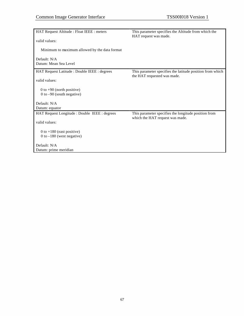
Common Image Generator Interface TSS00I018 Version 1
67
HAT Request Altitude : Float IEEE : meters valid values: Minimum to maximum allowed by the data format Default: N/A Datum: Mean Sea Level
This parameter specifies the Altitude from which the HAT request was made.
HAT Request Latitude : Double IEEE : degrees valid values: 0 to +90 (north positive) 0 to –90 (south negative) Default: N/A Datum: equator
This parameter specifies the latitude position from which the HAT requested was made.
HAT Request Longitude : Double IEEE : degrees valid values: 0 to +180 (east positive) 0 to –180 (west negative) Default: N/A Datum: prime meridian
This parameter specifies the longitude position from which the HAT request was made.

Common Image Generator Interface TSS00I018 Version 1
68
4.17 Line of Sight Occult Request
The Line of Sight Occult Request data packet is contained in the Ethernet message sent from the Host to the IG. It is used to determine intervisibility or occulting between a source and destination point. The answer to the LOS Occult request is contained in the Line of Sight Response data packet, section 4.21. To match up requests from the host with responses from the IG, the “LOS ID” parameter is used. The same number that is placed in this parameter will be returned in the “LOS ID” parameter of the corresponding Line of Sight data packet to uniquely identify the response. The “LOS ID” value should be manipulated in such a way as to not duplicate the value in a reasonable amount of time, say one second. This will prevent similarly identified requests from being lost by the IG. There is no restriction on the number of LOS requests that can be make in a single frame. The user should be aware however that the response time of the IG might be degraded under conditions that overload the IG LOS computation mechanism. Valid LOS responses will only be returned for locations on the current database. Refer to the applicable Database and Entity Attribute Definition Document (s) for details on the extent of the Database. The contents of the Line of Sight Occult Request data packet can be seen below.
31 30 29 28 27 26 25 24 23 22 21 20 19 18 17 16 15 14 13 12 11 10 9 8 7 6 5 4 3 2 1 0 Packet ID = 42 Packet size = 48 bytes LOS ID
LOS Request Altitude Source LOS Request Latitude Source (MSW) LOS Request Latitude Source (LSW)
LOS Request Longitude Source (MSW) LOS Request Longitude Source (LSW)
Spare LOS Request Altitude Destination
LOS Request Latitude Destination (MSW) LOS Request Latitude Destination (LSW)
LOS Request Longitude Destination (MSW) LOS Request Longitude Destination (LSW)
Line of Sight Occult Request parameter definitions: Formats and Ranges Description Packet ID = 42 : unsigned char : N/A This parameter identifies this data packet as a Line of
Sight Occult Request data packet.
There can be multiple instances of this data packet per frame. Each instance should uniquely identify a LOS request by its LOS ID parameter. If the same value for LOS ID is used more than once in a frame, the last data packet received will be used.
Packet size : unsigned char : N/A This parameter indicates the number of bytes in this data packet.

Common Image Generator Interface TSS00I018 Version 1
69
LOS ID : unsigned short : N/A valid values: 0 to 65535 Default: 0
This parameter is used to identify the LOS request so that when the answer to the request is returned it can be identified by the host. This is done via the LOS ID parameter of the Line of Sight Response data packet.
The response to a Line of Sight Occult Request is returned in the Line of Sight Response data packet. Because the LOS ID is shared between the Line of Sight Occult Request, the Line of Sight Range Request, and the Line of Sight Point Request the LOS ID parameters assigned for these queries should be unique between the three request types.
LOS Request Altitude Source : Float IEEE : meters valid values: Minimum to maximum allowed by the data format Default: N/A Datum: Mean Sea Level
This parameter specifies the altitude of the source point for the LOS request vector.
LOS Request Latitude Source: Double IEEE : degrees valid values: 0 to +90 (north positive) 0 to –90 (south negative) Default: N/A Datum: prime meridian
This parameter specifies the latitude position of the source point for the LOS request vector.
LOS Request Longitude Source: Double IEEE : degrees valid values: 0 to +180 (east positive) 0 to –180 (west negative) Default: N/A Datum: prime meridian
This parameter specifies the longitude position of the source point for the LOS request vector.
LOS Request Altitude Destination : Float IEEE : meters valid values: Minimum to maximum allowed by the data format Default : N/A Datum: Mean Sea Level
This parameter specifies the altitude of the destination point for the LOS request vector.

Common Image Generator Interface TSS00I018 Version 1
70
LOS Request Latitude Destination: Double IEEE : degrees valid values: 0 to +90 (north positive) 0 to –90 (south negative) Default: N/A Datum: prime meridian
This parameter specifies the latitude position of the destination point for the LOS request vector.
LOS Request Longitude Destination: Double IEEE : degrees valid values: 0 to +180 (east positive) 0 to –180 (west negative) Default: N/A Datum: prime meridian
This parameter specifies the longitude position of the destination point for the LOS request vector.

Common Image Generator Interface TSS00I018 Version 1
71
4.18 Line of Sight Range Request
The Line of Sight Range Request data packet is contained in the Ethernet message sent from the Host to the IG. It is used to determine the range from a source point to an object within the environment. A maximum range is specified in order to constrain the search, if desired. The answer to the LOS Range Request is contained in the Line of Sight Response data packet, section 4.21. To match up requests from the host with responses from the IG, the “LOS ID” parameter is used. The same number that is placed in this parameter will be returned in the “LOS ID” parameter of the corresponding Line of Sight Response data packet to uniquely identify the response. The “LOS ID” value should be manipulated in such a way as to not duplicate the value in a reasonable amount of time, say one second. This will prevent similarly identified requests from being lost by the IG. There is no restriction on the number of LOS requests that can be make in a single frame. The user should be aware however that the response time of the IG might be degraded under conditions that overload the IG LOS computation mechanism. The IG will only return valid LOS data if an intersection is detected within the LOS Request Maximum Distance as specified in this data packet, and the request is located within the current database. Refer to the applicable Database and Entity Attribute Definition Document (s) for details on the extent of the Database. The contents of the Line of Sight Occult Request data packet can be seen below.
31 30 29 28 27 26 25 24 23 22 21 20 19 18 17 16 15 14 13 12 11 10 9 8 7 6 5 4 3 2 1 0 Packet ID = 43 Packet size = 40 bytes LOS ID
spare LOS Request Heading
LOS Request Pitch LOS Request Maximum Range LOS Request Altitude Source
LOS Request Latitude Source (MSW) LOS Request Latitude Source (LSW)
LOS Request Longitude Source (MSW) LOS Request Longitude Source (LSW)
Line of Sight Range Request parameter definitions: Formats and Ranges Description Packet ID = 43 : unsigned char : N/A This parameter identifies this data packet as a Line of
Sight Range Request data packet.
There can be multiple instances of this data packet per frame. Each instance should uniquely identify a LOS request by its LOS ID parameter. If the same value for identification is used more than once in a frame, the last data packet received will be used.
Packet size : unsigned char : N/A This parameter indicates the number of bytes in this data packet.

Common Image Generator Interface TSS00I018 Version 1
72
LOS ID : unsigned short : N/A valid values: 0 to 65535 Default: 0
This parameter is used to identify the LOS request so that when the answer to the request is returned it can be identified by the host. This is done via the LOS ID parameter of the Line of Sight Response data packet.
The response to a Line of Sight Range Request is returned in the Line of Sight Response data packet. Because the LOS ID is shared between the Line of Sight Occult Request, the Line of Sight Range Request, and the Line of Sight Point Request the LOS ID parameters assigned for these queries should be unique between the three request types.
LOS Request Heading : Float IEEE : degrees valid values: 0 to +360 clockwise Default: N/A Datum: see Figure 4.
This parameter specifies the heading of the requested LOS.
LOS Request Pitch : Float IEEE : degrees valid values: 0 to +90 up 0 to –90 down Default: N/A Datum: see Figure 4.
This parameter specifies the pitch of the requested LOS.
LOS Request Maximum Distance : Float IEEE : meters valid values: 0 to maximum allowed by the data format Default: N/A
This parameter specifies the maximum distance for which LOS measurement is achievable for the requested LOS.
LOS Request Altitude Source: Float IEEE : meters valid values: Minimum to maximum allowed by the data format Default: N/A Datum: Mean Sea Level, see Figure 3.
This parameter specifies the altitude of the source point LOS request vector.
LOS Request Latitude Source: Double IEEE : degrees valid values: 0 to +90 (north positive) 0 to –90 (south negative) Default: N/A Datum: equator, see Figure 3.
This parameter specifies the latitude position of the source point LOS request vector.

Common Image Generator Interface TSS00I018 Version 1
73
LOS Request Longitude Source: Double IEEE : degrees valid values: 0 to +180 (east positive) 0 to –180 (west negative) Default: N/A Datum: prime meridian, see Figure 3.
This parameter specifies the longitude position of the source point for the LOS request vector.

Common Image Generator Interface TSS00I018 Version 1
74
4.19 Start of Frame
The Start of Frame data packet is contained in the Ethernet message sent from the IG to the Host. When the Host receives the Start of Frame data packet it should respond immediately with the Host to IG Ethernet message containing all mandatory data packets and any other data packets necessary to describe data changes to the IG. The contents of the Start of Frame data packet can be seen below.
31 30 29 28 27 26 25 24 23 22 21 20 19 18 17 16 15 14 13 12 11 10 9 8 7 6 5 4 3 2 1 0 Packet ID = 101 Packet size = 12 bytes CIGI version number = 1 Database Number IG Status Code *1 Spare
IG to Host Frame Counter
Start of Frame parameter definitions: Formats and Ranges Description Packet ID = 101 : unsigned char : N/A This parameter identifies this data packet as the Start of
Frame data packet. There will be only one instance of this data packet per frame.
Packet size : unsigned char : N/A This parameter indicates the number of bytes in this data packet.
CIGI version number : unsigned char : N/A valid values: 0 – 255 Default: N/A
This parameter indicates the version of the CIGI interface that is currently running on the image generator. The host can use this number to determine concurrency.
Database Number : signed char : N/A valid values: -128 The requested database is not available -99 to –1 The requested database is being loaded 0 No database is loaded or being loaded +1 to +99 The designated database is loaded See the Database Number table in the applicable Database and Entity Attribute Definition Document(s). Default = N/A
This parameter indicates load status of the requested database. The IG will return a value of –128 while the Host is requesting a database that is not available. See the Database Number description for the IG Control data packet, section 4.3 for a further discussion on database loading theory.
IG Status Code : unsigned char : N/A valid values: 0 – normal operation 1 – 255 See assignments in Table 3. Default: 0
This parameter indicates the operating status of the IG including any error status message that may apply.

Common Image Generator Interface TSS00I018 Version 1
75
*1 Current IG Mode : 2 bit field : N/A valid values: 0 = standby (reset) 1 = operate 2 = debug 3 = off-line maintenance Default: 0
This parameter identifies to the Host the current operating mode of the IG. Standby (reset): This is the mode that the IG will be initialized to during start up. In this mode the IG will initialize the mission scenario to begin a new mission. That is to say all entities that were instantiated during a previous mission will be removed from the display. While in this mode the IG will only send the Start Of Frame data packet to the Host and will ignore Host inputs except for mode changes commanded in the IG Mode Change parameter of the IG Control data packet. Also during this mode the IG may be put into maintenance mode via a graphical user interface provided on the IG. Operate: In this mode the IG will except all data packet types destine for the IG. The IG will also return all data packet types appropriate for real-time operation. While in this mode the IG will report errors to the Host via the IG Status Code parameter of this data packet. Because of the real-time nature of the operate mode status codes are provided only for informational purposes. If further investigation is necessary the debug mode should be used in a non-real-time fashion. Debug: In this mode the IG will except all data packet types destine for the IG. The IG will also return all data packet types appropriate for real-time operation. This mode can be used as a diagnostic tool while integrating or trouble shooting the Host and IG interface. Because of error status archiving that takes place during this mode the IG may not always operate in a real-time fashion. While in this mode the IG will report errors to the Host via the IG Status Code parameter of this data packet. Also, because there can be more than one status code generated per frame and this data field can only describe one status per frame an archive of all status messages is kept on the IG. This archive can be viewed using a graphical user interface provided on the IG. Typically status logs are regenerated each time the CIGI is started. However status archives can be saved for later diagnosis via a graphical user interface provided on the IG. Off-line maintenance: The off-line maintenance mode is entered from the IG. While the IG is in off-line maintenance mode the Host can not change the IG mo de. The IG will require a mode change to standby (reset) from within the IG before the Host can command a mode change. While in this mode the IG will only send the Start Of Frame data packet to the Host and will ignore all Host commands. When the IG transitions from a mode where it is ignoring Host commands it is the responsibility of the Host to initialized to the proper mission scenario start conditions.

Common Image Generator Interface TSS00I018 Version 1
76
IG to Host Frame Counter : unsigned integer : N/A valid values: 0 to 4,294,967,295 Default: N/A
This parameter contains a number representing a particular frame. It is incremented each frame by the IG. It is intended to be used in conjunction with the Host to IG Frame Counter parameter in the IG Control data packet to assist in correlating IG and Host frames. When this parameter reaches its maximum value it will roll back to zero.

Common Image Generator Interface TSS00I018 Version 1
77
4.20 Height Above Terrain Response
The Height Above Terrain Response data packet is contained in the Ethernet message sent from the IG to the Host. It is used to respond to a Height Above Terrain Request. To match up requests from the host with responses from the IG the “HAT ID” parameter is used. The number that is placed in this field is the same as that used in the “HAT ID” in the Height Above Terrain Request data packet that made the original request. See the Height Above Terrain Request data packet narrative for more information on this correlation scheme in section 4.16. The contents of the Height Above Terrain Response data packet can be seen below.
31 30 29 28 27 26 25 24 23 22 21 20 19 18 17 16 15 14 13 12 11 10 9 8 7 6 5 4 3 2 1 0 Packet ID = 102 Packet size = 16 bytes HAT ID
*1 spare Material Code
HAT Response Altitude
Height Above Terrain Response parameter definitions: Formats and Ranges Description Packet ID = 102 : unsigned char : N/A This parameter identifies this data packet as a Height
Above Terrain Response data packet.
There can be multiple instances of this data packet per frame. Its HAT ID will uniquely identify each instance.
Packet size : unsigned char : N/A This parameter indicates the number of bytes in this data packet.
HAT ID : unsigned short : N/A valid values: 0 to 65535 Default: 0
This parameter identifies the HAT response corresponding to the associated HAT request. This parameter is provided to allow the host to match this response with the issued request.
*1 Response Validity : Boolean : N/A valid values: 0 = invalid 1 = valid Default: 0
This parameter is used to indicate whether the response is valid or invalid.
Material Code : integer : N/A valid values: See the Material code assignments in the applicable Database and Entity Attribute Definition Document (s). Default: N/A
This parameter specifies the Material Code of the object that the HAT test vector intersected.

Common Image Generator Interface TSS00I018 Version 1
78
HAT Response Altitude: Float IEEE : meters valid values: Minimum to maximum allowed by the data format Default: N/A
This parameter represents the altitude above or below the terrain for the position requested in the Height Above Terrain Request data packet.

Common Image Generator Interface TSS00I018 Version 1
79
4.21 Line of Sight Response
The Line of Sight Response data packet is contained in the Ethernet message sent from the IG to the Host. It is used to respond to a Line Of Sight Request. To match up requests from the host with responses from the IG the “LOS ID” parameter is used. The number that is placed in this field is the same as that used in the “LOS ID” in the Line Of Sight Occult Request or the Line Of Sight Range Request data packet that made the original request. See the Line Of Sight Occult Request or the Line Of Sight Range Request data packet’s narrative for more information on this correlation scheme in sections 4.17 and 0. The contents of the Line of Sight Response data packet can be seen below.
31 30 29 28 27 26 25 24 23 22 21 20 19 18 17 16 15 14 13 12 11 10 9 8 7 6 5 4 3 2 1 0 Packet ID = 103 Packet size = 40 bytes LOS ID
*1 *2 Spare Spare
Material Code LOS Range Response
LOS Intersection Altitude LOS Intersection Latitude (MSW) LOS Intersection Latitude (LSW)
LOS Intersection Longitude (MSW) LOS Intersection Longitude (LSW)
Line of Sight Response parameter definitions: Formats and Ranges Description Packet ID = 103 : unsigned char : N/A This parameter identifies this data packet as a Line of
Sight Response data packet.
There can be multiple instances of this data packet per frame. Its “LOS ID” will uniquely identify each instance.
Packet size : unsigned char : N/A This parameter indicates the number of bytes in this data packet.
LOS ID : unsigned short : N/A valid values: 0 to 65535 Default: 0
This parameter identifies the LOS response corresponding to the associated LOS request. This parameter is provided to allow the host to match this response with the issued request.
*1 Response Validity : Boolean : N/A valid values: 0 = invalid 1 = valid Default: 0
This parameter is used to indicate whether the response is valid or invalid.
*2 LOS Occult Response : Boolean : N/A valid values: 0 = occulted 1 = visible Default: 0
This parameter is used to respond to the LOS Occult Request data packet. It indicates whether the destination point is visible from the source point. This field is not applicable to the LOS Range Request data packet.

Common Image Generator Interface TSS00I018 Version 1
80
Material Code : integer : N/A valid values: See the Material code assignments in the applicable Database and Entity Attribute Definition Document (s). Default: N/A
This parameter specifies the Material Code of the object that the LOS test vector intersected.
LOS Range Response: Float IEEE : meters valid values: -1 = beyond requested LOS Maximum Range 0 to maximum allowed by the data format Default: N/A
This parameter is used to respond to the Line of Sight Range Request data packet. If an object was not intersected before the specified LOS Maximum Range in the Line of Sight Range Request data packet was reached the Response Validity will indicate valid and the LOS Range Response will indicate a negative one (-1).
LOS Intersection Altitude : Float IEEE : meters valid values: Minimum to maximum allowed by the data format Default: N/A Datum: Mean Sea Level, see Figure 3.
This parameter specifies the altitude of the intersection point of the LOS request vector with an object. If the LOS Range Response in this data packet contains a -1 this altitude value should be ignored.
LOS Intersection Latitude : Double IEEE : degrees valid values: 0 to +90 (north positive) 0 to –90 (south negative) Default: N/A Datum: equator, see Figure 3.
This parameter specifies the latitude of the intersection point of the LOS request vector with an object. If the LOS Range Response in this data packet contains a -1 this latitude value should be ignored.
LOS Intersection Longitude : Double IEEE : degrees valid values: 0 to +180 (east positive) 0 to –180 (west negative) Default: N/A Datum: prime meridian, see Figure 3.
This parameter specifies the longitude of the intersection point of the LOS request vector with an object.
If the LOS Range Response in this data packet contains a -1 this longitude value should be ignored.

Common Image Generator Interface TSS00I018 Version 1
81
4.22 Collision Detection Response
The Collision Detection Response data packet is contained in the Ethernet message sent from the IG to the Host. There can be up to 128 impact locations specified on an entity. These are uniquely identified using the Collision “VECTOR ID” of the Collision Detection Definition data packet. This data packet will be returned if the following three conditions are true, a collision occurs, the vector “ENABLE” parameter in the Collision Detection Definition data packet is enabled, and the “COLLISION DETECTION REQUEST” switch in the Entity Control data packet is enabled. Explanations of these parameters can be seen in their respective sections of this document. The contents of the Collision Detection Response data packet can been seen below.
31 30 29 28 27 26 25 24 23 22 21 20 19 18 17 16 15 14 13 12 11 10 9 8 7 6 5 4 3 2 1 0 Packet ID = 104 Packet size = 24 bytes Entity ID Vector ID Spare
Surface Material Code Collision Point X Collision Point Y Collision Point Z
Collision Detection Response parameter definitions: Formats and Ranges Description Packet ID = 104 : unsigned char : N/A This parameter identifies this data packet as a Collision
Detection Response data packet.
There can be multiple instances of this data packet per frame. Its Vector ID and Entity ID will uniquely identify each instance.
Packet size : unsigned char : N/A This parameter indicates the number of bytes in this data packet.
Entity ID : unsigned short : N/A valid values: 0 to 65535 Default: N/A
This parameter indicates which entity experienced a collision.
Vector ID : 7 bit field : N/A valid values: 0 to 127 Default: N/A
This parameter identifies the collision vector corresponding to the associated Collision Detection request. This parameter is provided to allow the host to match this response with the issued request.
Surface Material Code: integer : N/A valid values: See the Material code assignments in the applicable Database and Entity Attribute Definition Document (s). Default: N/A
This parameter specifies the Material Code of the surface that this collision test vector contacted.

Common Image Generator Interface TSS00I018 Version 1
82
Collision Point X: Float IEEE: meters valid values: Minimum to maximum allowed by the data format limited to the extent of the vector Default: N/A Datum: Entity coordinate system, see Figure 6.
This parameter specifies the position of the collision point in the X-axis where the vector collided with a surface. This point will lie upon the defined vector.
Collision Point Y: Float IEEE: meters valid values: Minimum to maximum allowed by the data format limited to the extent of the vector Default: N/A Datum: Entity coordinate system, see Figure 6.
This parameter specifies the position of the collision point in the Y-axis where the vector collided with a surface. This point will lie upon the defined vector.
Collision Point Z: Float IEEE: meters valid values: Minimum to maximum allowed by the data format limited to the extent of the vector Default: N/A Datum: Entity coordinate system, see Figure 6.
This parameter specifies the position of the collision point in the Z-axis where the vector collided with a surface. This point will lie upon the defined vector.

Common Image Generator Interface TSS00I018 Version 1
83
4.23 Sensor Response
The Sensor Response data packet is contained in the Ethernet message sent from the IG to the Host. It is used to report aspects of the Sensor tracker to the Host. If the sensor specified by the Sensor ID is active this packet must be returned to the host.
Figure 23 - Gate Offset and Size
The contents of the Sensor Response data packet can be seen below.
31 30 29 28 27 26 25 24 23 22 21 20 19 18 17 16 15 14 13 12 11 10 9 8 7 6 5 4 3 2 1 0 Packet ID = 105 Packet size = 12 bytes View ID *1 S Sensor ID
Target X Offset Target Y Offset Gate X Size Gate Y Size
Sensor Response parameter definitions: Formats and Ranges Description Packet ID = 105 : unsigned char : N/A This parameter identifies this data packet as Sensor
Response data packet. There will be one of these data packets for each active Sensor view.
Packet size : unsigned char : N/A This parameter indicates the number of bytes in this data packet.
View ID: 5 bit field : N/A valid value: 0 – 31 Default N/A
This parameter indicates what Sensor view this data packet is applicable to.
Gate Y Offset
(degrees)
Gate X Offset
(degrees)
View plane normal
Sensor Gate
Gate X size
Gate Y size

Common Image Generator Interface TSS00I018 Version 1
84
*1 Sensor Status : 2 bit field : N/A valid values: 0 = Searching for target 1 = Tracking 2 = Impending Breaklock 3 = Breaklock Default = 0
This parameter indicates what mode the Sensor is currently in.
Sensor ID : unsigned char : N/A valid values: 0 to 255 Default: 0
This parameter identifies the Sensor response corresponding to the associated Sensor Control data packet. This parameter is provided to allow the host to match this response with the issued Sensor Control data packet and its associated data packets.
Gate X Offset: angle format (16 bit): degrees valid values: plus and minus values bounded by the specified view Default = 0 Datum: see Figure 23.
This parameter specifies the target’s horizontal offset from the view plane normal.
Gate Y Offset: angle format (16 bit): degrees valid values: plus and minus values bounded by the specified view Default = 0 Datum: see Figure 23.
This parameter specifies the target’s vertical offset from the view plane normal.
Gate X Size: unsigned short : See note to right valid values: 0 to maximum required Default = 0 Datum: see Figure 23.
This parameter specifies the target size in the x direction (horizontal) in pixels. Note – The units can be either pixels or lines depending on the view rotation.
Gate Y Size: unsigned short : See note to right valid values: 0 to maximum required Default = 0 Datum: see Figure 23.
This parameter specifies the target size in the y direction (vertical) in pixels. Note – The units can be either pixels or lines depending on the view rotation.

Common Image Generator Interface TSS00I018 Version 1
85
5. Error Messages
Following is a table of error message definitions that are reported from the CIGI to the Host in the IG Status parameter of the Start of Frame data packet described in section 4.19.
Table 3 – CIGI error messages
IG Status Number
Error Description
0 Normal Operation 1 The IG Control data packet was not the first data packet detected in the Host-to-CIGI message. 2 Invalid Entity Type in Entity Control data packet. 3 An Entity Control data packet contains an inactive Parent Entity ID. 4 A Component Control data packet contains an inactive Entity ID. 5 A Component Control data packet contains an invalid Component ID. 6 A Component Control data packet contains an invalid Component State. 7 A Component Control data packet contains an invalid Component Value. 8 An Articulated Part Control data packet contains an invalid Articulated Part ID. 9 An Articulated Part Control data packet contains an inactive Entity ID. 10 A Rate Control data packet contains an inactive Entity ID. 11 A Rate Control data packet contains an invalid Articulated Part ID. 12 An Environment Control data packet contains values are outside the specified range. 13 A View Control data packet contains an undefined view group. 14 A View Control data packet contains an undefined view. 15 A Sensor Control data packet contains an invalid value for Scene/Target track mode on/off. 16 A Trajectory Definition data packet contains an inactive Entity ID. 17 A Special Effects Definition data packet contains an inactive Entity ID. 18 A View Definition data packet contains an undefined view. 19 A View Definition data packet specified the Field of View Left value greater than the right. 20 A View Definition data packet specified the Field of View Right value less than the left. 21 A View Definition data packet specified the Field of View Top value less than the bottom. 22 A View Definition data packet specified the Field of View Bottom value greater than the top. 23 A Collision Detection Definition data packet contains an inactive Entity ID.

Common Image Generator Interface TSS00I018 Version 1
86
6. Acronyms
AAR Air-to-Air Refueling CG Center of Gravity HAT Height Above Terrain HPR Heading, Pitch, Roll Hz Hertz I/O Input / Output ICD Interface Control Document ID Identification IFF Identify Friend or Foe IG Image Generator IP Internet Protocol IEEE Institute of Electrical and Electronic Engineers LOS Line-of-Sight LSW Least Significant Word ms Millisecond(s) MSL Mean Sea Level MSW Most Significant Word N/A Not Applicable OFS Operational Flight Simulator OTW Out The Window SOF Start Of Frame RTM Real Time Monitor TBD To Be Determined TPS Target Projection System UDP User Datagram Protocol WRT With Respect To