interface module adapter - auser oy · interface module adapter for simatic s7 version v1.2 file:...
TRANSCRIPT

Interface Module Adapter for SIMATIC S7
Version V1.2 File: AdapterEng_V1_2.doc Page 1 of 12 Date of issue June 05
Automation & Drives
Interface Module Adapter
6EZ2 for SIMATIC S7-400
Short Description June 2005
Innovation on economical base Talking to our customers there seems to be always a common problem : many plants are still operating with automation systems of the previous generation and although the performance is still sufficient, it will become increasingly difficult to get spare parts and to have an efficient service in the future.
To be up to date, it will be necessary to replace the existing system with a modern unit. But quite often this decision is delayed by the fear of disruption of the running production and the inconvenience of long term trouble shooting in case of miswiring. But that could be avoided!

Interface Module Adapter for SIMATIC S7
Version V1.2 File: AdapterEng_V1_2.doc Page 2 of 12 Date of issue June 05
Automation & Drives
1 Application Retrofit at ease Siemens engineers have developed an elegant method to solve your problem: • in very short time • without errors • on a low cost level The Interface Module Adapter 6EZ2 for SIMATIC S7 400 links the old with the new : field proven production systems with the latest achievements in automation systems. You simply take off the front plug of the I/O units, replace the automation system by a S7 400 , plug in the IMA and fix the front plug back on to the adapter. You see, all is done easily by plugins. And after installation of the STEP 7 software you can continue with you production. To provide you with the adequate software, Siemens engineers will be at your service.
Advantages are obvious • low engineering costs in the hardware. Only a
replacement of the controller is necessary, all wiring remains at its place
• schematic diagrams don’t have to be revised, signals lists are automatically updated by the software
• Shutdown time of the production is reduced. This procedure not only saves you a lot of time and money, but also reduces errors. Your direct Partners Please contact on all technical or commercial questions Dieter Koller Telefon: +49 (711) 137-2655 Fax: +49 (711) 137-2056 eMail: [email protected] or Thomas Hener Telefon: +49 (711) 137-2569 Fax: +49 (711) 137-2056 eMail: [email protected] SIEMENS AG RD SDW STG A&D B31 Weissacher Str. 11 D-70499 Stuttgart
Interface Module Adapter for SIMATIC S7
Version V1.2 File: AdapterEng_V1_2.doc Page 3 of 12 Date of issue June 05
Automation & Drives
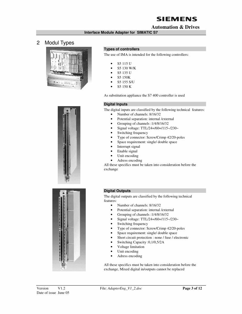
2 Modul Types
Types of controllers The use of IMA is intended for the following controllers:
• S5 115 U • S5 130 W/K • S5 135 U • S5 150K • S5 155 S/U • S5 150 K
As substitution appliance the S7 400 controller is used
Digital Inputs The digital inputs are classified by the following technical features:
• Number of channels: 8/16/32 • Potential separation: internal /external • Grouping of channels :1/4/8/16/32 • Signal voltage: TTL/24=/60=/115~/230~ • Switching frequency • Type of connector: Screw/Crimp 42/20-poles • Space requirement: single/ double space • Interrupt signal • Enable signal • Unit encoding • Adress encoding
All these specifics must be taken into consideration before the exchange
Digital Outputs The digital outputs are classified by the following technical features:
• Number of channels: 8/16/32 • Potential separation: internal /external • Grouping of channels :1/4/8/16/32 • Signal voltage: TTL/24=/60=/115~/230~ • Switching frequency • Type of connector: Screw/Crimp 42/20-poles • Space requirement: single/ double space • Short circuit protection : none / fuse / electronic • Switching Capacity :0,1/0,5/2A • Voltage limitation • Unit encoding • Adress encoding
All these specifics must be taken into consideration before the exchange, Mixed digital in/outputs cannot be replaced
Interface Module Adapter for SIMATIC S7
Version V1.2 File: AdapterEng_V1_2.doc Page 4 of 12 Date of issue June 05
Automation & Drives
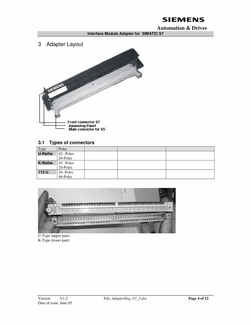
3 Adapter Layout
3.1 Types of connectors Type Poles U-Reihe 42 –Poles
20-Poles
K-Reihe 43 –Poles 20-Poles
115 U 24- Poles 46-Poles
U-Type (upper part) K-Type (lower part)
Interface Module Adapter for SIMATIC S7
Version V1.2 File: AdapterEng_V1_2.doc Page 5 of 12 Date of issue June 05
Automation & Drives
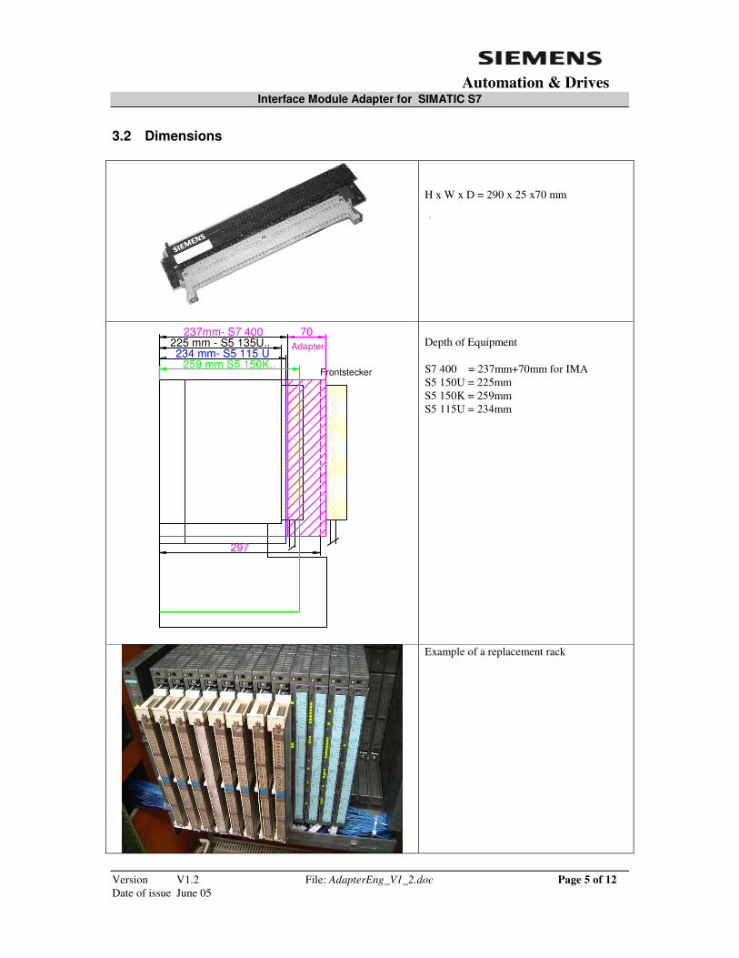
3.2 Dimensions
H x W x D = 290 x 25 x70 mm
225 mm - S5 135U..
Frontstecker
Adapter70
234 mm- S5 115 U
237mm- S7 400
297
259 mm S5 150K..
Depth of Equipment S7 400 = 237mm+70mm for IMA S5 150U = 225mm S5 150K = 259mm S5 115U = 234mm
Example of a replacement rack

Interface Module Adapter for SIMATIC S7
Version V1.2 File: AdapterEng_V1_2.doc Page 6 of 12 Date of issue June 05
Automation & Drives
3.3 Rack Size S7-400
S5 135 U /150 U
S5 150 K
S5 115U
Interface Module Adapter for SIMATIC S7
Version V1.2 File: AdapterEng_V1_2.doc Page 7 of 12 Date of issue June 05
Automation & Drives
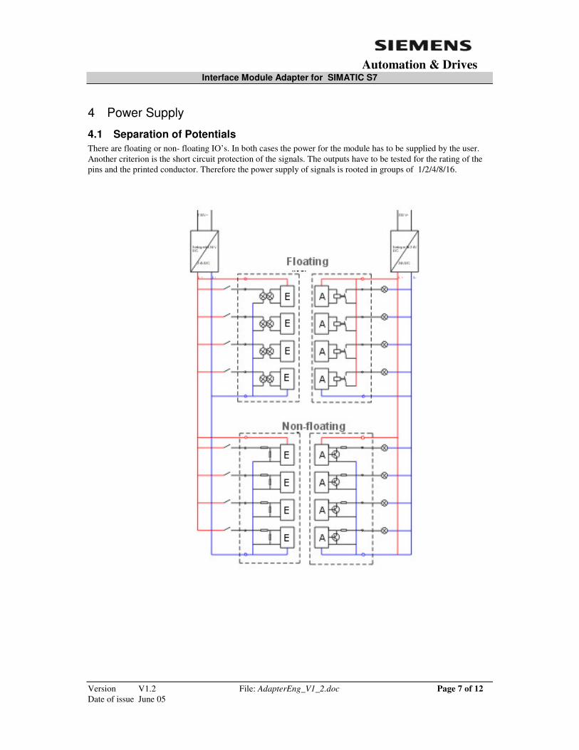
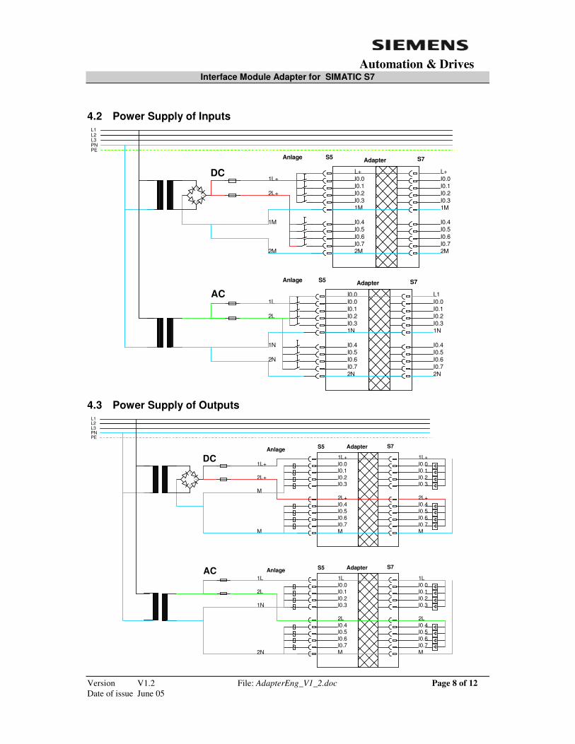
4 Power Supply
4.1 Separation of Potentials There are floating or non- floating IO’s. In both cases the power for the module has to be supplied by the user. Another criterion is the short circuit protection of the signals. The outputs have to be tested for the rating of the pins and the printed conductor. Therefore the power supply of signals is rooted in groups of 1/2/4/8/16.
Interface Module Adapter for SIMATIC S7
Version V1.2 File: AdapterEng_V1_2.doc Page 8 of 12 Date of issue June 05
Automation & Drives
4.2 Power Supply of Inputs L1L2L3PNPE
1L+
2L+
1M
DCI0.0I0.1I0.2I0.3
AC
I0.4I0.5I0.6I0.7
2M 2M
1M
I0.0I0.1I0.2I0.3
I0.4I0.5I0.6I0.72M
1M
Adapter
L+
I0.0I0.1I0.2I0.3
I0.4I0.5I0.6I0.7
1N
2N
L11L
2L
1N
2N
I0.0I0.1I0.2I0.3
I0.4I0.5I0.6I0.7
Adapter
I0.0
1N
2N
L+
S5 S7
S5 S7
Anlage
Anlage
4.3 Power Supply of Outputs L1L2L3PNPE
1L+
2L+
DCI0.0I0.1I0.2I0.3
AC
I0.4I0.5I0.6I0.7
I0.0I0.1I0.2I0.3
I0.4I0.5I0.6I0.7
Adapter
1L
2L
Anlage S5 S7
1L+
M
1L+
2L+2L+
MM
M
I0.0I0.1I0.2I0.3
I0.4I0.5I0.6I0.7
I0.0I0.1I0.2I0.3
I0.4I0.5I0.6I0.7
AdapterAnlage S5 S7
MM
1N
2N
1L
2L
1L
2L

Interface Module Adapter for SIMATIC S7
Version V1.2 File: AdapterEng_V1_2.doc Page 9 of 12 Date of issue June 05
Automation & Drives
4.4 Rooting (germ: Wurzelung)
+-
4 er-WurzelungEEEE
AAAA
-+
+-
EE
AA -
+
+-
EEEE
AAAA
-+
2 er-Wurzelung
8er-Wurzelung
EEEE
AAAA
+-
E A-+
1 er-Wurzelung
+E A
-1
16 er-Wurzelung1
- E16 +A16
+E A
-11
- E +A
32 er-Wurzelung
32 32

Interface Module Adapter for SIMATIC S7
Version V1.2 File: AdapterEng_V1_2.doc Page 10 of 12 Date of issue June 05
Automation & Drives
5 Order-Numbers SIMATIC S5 SIMATIC S7 Adapter S5 135 /155U S7 400 Basis I/O Type Channel Voltage Current Type Order-Numbers DI 6ES5 420- 4UA14 32 24= 0 6ES7 421- 1BL01- 0AA0 6EZ2 041-8UG 07-0EU36 430- 4UA14 32 24= 0 1BL01- 0AA0 6EZ2 041-8UG 07-0EU36 431- 4UA12 16 24/60DC 0 7DH00- 0AB0 6EZ2 041-8UG 07-0EU20 432- 4UA12 32 24= 0 1BL01- 0AA0 6EZ2 041-8UG 07-0EU33 435- 4UA12 16 24/60AC 0 7DH00- 0AB0 6EZ2 041-8UG 37-1EU23 436- 4UA12 16 115/230AC 0 1FH20- 0AA0 6EZ2 041-8UG 57-1EU23 436- 4UB12 8 115/230AC 0 1FH20- 0AA0 6EZ2 041-8UG 57-1EU20
DO 6ES5 441- 4UA14 32 24= 0,5A 6ES7 422- 1BL00- 0AA0 6EZ2 041-8UG 07-0AU36 451- 4UA14 32 24= 0,5A 1BL00- 0AA0 6EZ2 041-8UG 07-0AU36 453- 4UA12 16 24= 2A 1HH00- 0AA0 6EZ2 041-8UG 07-1AU21 454- 4UA14 16 24= 2A 1BH11- 0AA0 6EZ2 041-8UG 07-1AU23 456- 4UA12 16 115/230AC 2A 1FH00- 0AA0 6EZ2 041-8UG 57-1AU23 458- 4UC11 16 Rel 0 1HH00- 0AA0 6EZ2 041-8UG 67-0AU23
AI 6ES5 460- 4UA13 8 Only current
metering 6ES7 431- 1KF00- 0AB0 6EZ2 041-8UG 77-0EU11
460- 4UA13 8 Only voltage
metering 1KF00- 0AB0 6EZ2 041-8UG 77-0EU12
465- 4UA13 8 Only PT100 7KF10- 0AB0 6EZ2 041-8UG 77-0EU20
465- 4UA13 16 Current and voltage
metering 0HH00- 7QH00-
0AB0 0AB0 6EZ2 041-8UG 77-0EU21
AO 6ES5 470- 4UA13 8 Only current output 6ES7 432- 1HF00- 0AB0 6EZ2 041-8UG 77-0AU11
470- 4UC13 8 Only current output 1HF00- 0AB0 6EZ2 041-8UG 77-0AU11
470- 4UA13 8 Only voltage output 1HF00- 0AB0 6EZ2 041-8UG 77-0AU12
470- 4UB13 8 Only voltage output 1HF00- 0AB0 6EZ2 041-8UG 77-0AU12
470- 4UC13 8 Only voltage output 1HF00- 0AB0 6EZ2 041-8UG 77-0AU12

Interface Module Adapter for SIMATIC S7
Version V1.2 File: AdapterEng_V1_2.doc Page 11 of 12 Date of issue June 05
Automation & Drives
SIMATIC S5 SIMATIC S7 Adapter S5 130 /150K S7 400-Basis I/O Type Channel Voltage Current Type Order-Numbers DI 6ES5 420- 3BA11 32 24= 0 6ES7 421- 1BL01- 0AA0 6EZ2 041-8UG 08-0EK36 430- 3BA11 32 24= 0 1BL01- 0AA0 6EZ2 041-8UG 08-0EK36 431- 3BA11 16 24..60= 0 7DH00- 0AB0 6EZ2 041-8UG 18-0EK23
DO 6ES5 442- 3AA11 32 24= 10mA 6ES7 422- 1BL00- 0AA0 6EZ2 041-8UG 08-0AK30 444- 3AA11 16 24= 2A 1BH11- 0AA0 6EZ2 041-8UG 08-1AK24 445- 3AA12 32 24= 0,5A 1BL00- 0AA0 6EZ2 041-8UG 08-0AK34 450- 3AA11 32 24= 0,12A 1BL00- 0AA0 6EZ2 041-8UG 08-0AK34 451- 3AA11 16 24= 0,5A 1BH11- 0AA0 6EZ2 041-8UG 08-0AK23
SIMATIC S5 SIMATIC S7 Adapter S5 115U S7 400-Basis I/O Type Channel Voltage Current Type Order-Numbers DI 6ES5 420- 7LA11 32 24= 0 6ES7 421- 1BL01- 0AA0 6EZ2 041-8UG 05-0EU36 430- 7LA12 32 24= 0 1BL01- 0AA0 6EZ2 041-8UG 05-0EU36 431- 7LA11 16 24-48UC 0 7DH00- 0AB0 6EZ2 041-8UG 65-0EU22 432- 7LA11 16 48-60UC 0 7DH00- 0AB0 6EZ2 041-8UG 65-0EU22 434- 7LA12 8 24= 0 7DH00- 0AB0 6EZ2 041-8UG 05-0EU10 435- 7LA11 16 115UC 0 1FH20- 0AA0 6EZ2 041-8UG 55-0EU22 435- 7LB11 16 115UC 0 1FH20- 0AA0 6EZ2 041-8UG 55-0EU21 435- 7LC11 8 115UC 0 1FH20- 0AA0 6EZ2 041-8UG 55-0EU10 436- 7LA11 16 230UC 0 1FH20- 0AA0 6EZ2 041-8UG 55-0EU22 436- 7LB11 16 230UC 0 1FH20- 0AA0 6EZ2 041-8UG 55-0EU21 436- 7LC11 8 230UC 0 1FH20- 0AA0 6EZ2 041-8UG 55-0EU10
DO 6ES5 441- 7LA11 32 24= 0,5A 6ES7 422- 1BL00- 0AA0 6EZ2 041-8UG 05-0AU33 451- 7LA11 32 24= 0,5A 1BL00- 0AA0 6EZ2 041-8UG 05-0AU33 451- 7LA21 32 24= 0,5A 1BL00- 0AA0 6EZ2 041-8UG 05-0AU33 454- 7LA11 16 24= 2A 1BH11- 0AA0 6EZ2 041-8UG 05-0AU22 455- 7LA11 16 115AC 2A 1HH00- 0AA0 6EZ2 041-8UG 45-0AU21 456- 7LA11 16 230AC 1A 1FH00- 0AA0 6EZ2 041-8UG 55-0AU22 458- 7LA11 16 Rel 0,5A 1HH00- 0AA0 6EZ2 041-8UG 65-0AU20 458- 7LC11 16 Rel 5A 1HH00- 0AA0 6EZ2 041-8UG 65-0AU22
AI 465- 7LA13 8 Only PT100 6ES7 431- 7KF10- 0AB0 6EZ2 041-8UG 75-0EU20
465- 7LA13 16 Current and voltage
metering 0HH00- 7QH00-
0AB0 0AB0 6EZ2 041-8UG 75-0EU21
Attention: Front Connector from S5/115U need more place (Width) !
Interface Module Adapter for SIMATIC S7
Version V1.2 File: AdapterEng_V1_2.doc Page 12 of 12 Date of issue June 05
Automation & Drives
6 Conditions of Sale 1. The Interface Module Adapters 6EZ2 041-8UG.. are intended to be used between the front-plugs on the I-O-modules of an obsolete controller and a modern replacement controller SIMATIC S 7. Hereby all installation remains at its place, only the controller and the respective software have to be substituted. For the substitution of the up to now used units the best matching units of S7- components were selected. However there remains a certain deviation in the specific performance. It is up to the user to check the limitations of his own installation, in particular the:
• Power supply • Signal voltage • Line-frequency • Limits of I-O-definitions • Rooting • Number of channels • Loading capacity • Rating of connectors • Signal switching frequency
2. If S7-units do require an external application of +/- potentials and the old installation did not supply them, these potentials have to be brought to the terminal block on the adapter. 3. If the power-rooting of the old installation is not corresponding to the new requirements, the user has to install the additional jumpers. 4. If the old installation was fed from different power sources an equipotential bonding contactor has to be applied. 5. The enable –signal of the S5 units is not present in the S7-system in an identical way and may be considered on handling. 6. The parametering and selection of modes in the I/O-units has to be done according to the requirements of the S7. 7. The vendor is not liable for damages that are caused by improper use of the Interface Module Adapters. It is recommended to perform a field-test before the general switch-over of the new installation.
8. Warranty Equipment sold hereunder is covered by a warranty against defects in material and workmanship for a period of one (1) year from date of shipment by Siemens provided the goods are submitted to normal use and services. The obligation under this warranty is limited to the repair or replacement at the Seller's option of definite parts. Provided that prompt notice of any defect is given by Purchaser to the Seller in writing within the applicable warranty period and that upon the Purchaser's return of the defective parts to the Seller properly packed and with transportation charges prepaid by purchaser, an inspection thereof shall reveal to the Seller's satisfaction that Purchaser's claim is valid under the term of this warranty. This warranty does not apply to equipment which is altered or repaired other than by persons authorized or approved by Siemens to perform such work, or if the Purchaser fails to operate and use the equipment sold hereunder in a safe and reasonable manner and in accordance with the manufacturer's written instructions