interfacial behaviour in tunnel engineering · interfacial behaviour in tunnel engineering problem...
TRANSCRIPT
Proceedings of the 2nd Fields–MITACS Industrial Problem-Solving Workshop, 2008
Interfacial Behaviour in Tunnel Engineering
Problem Presenter: Zongxi Cai (Northern Heavy Industries Group Co., Ltd.)
Academic Participants: C. Sean Bohun (UOIT), Hui-Hui Dai (City University of HongKong), Justin Findlay (UOIT), Matt Hennessy (UOIT), Peter Howell (University of Ox-ford), Huaxiong Huang (York University), Greg Lewis (UOIT), Roderick Melnik (WilfridLaurier University), Richard Moore (New Jersey Institute of Technology), Robert Miura(New Jersey Institute of Technology), John Ockendon (University of Oxford), Yonji Tan(Fudan University), Burt Tilley (Olin College of Engineering), Jonathan Wylie (City Uni-versity of Hong Kong)
Report prepared by: C. Sean Bohun1
Abstract. The stress induced in an underground tunnel due to the applied stressof a tunnel boring machine (TBM) is studied to understand the mechanisms whichlead to tunnel collapse. An investigation of the classical plane strain gravitationalproblem in a purely elastic medium shows that any fractures due to gravitationaleffects alone would occur at the base of the tunnel rather than the apex. Ignor-ing gravity we then explore an elastic/plastic solution in an idealized soil with nocohesion. To simulate the action of the TBM a point source is imparted on themedium extending in the horizontal direction. This model decouples into an elas-tostatic problem that predicts a wedge shaped region of plasticity extending fromthe point source and a hyperbolic flow problem in the plasticized region. Using asimilarity solution, it is shown that the behaviour of the medium is very sensitiveto the parameters that characterize the soil.
1 Introduction
Based in Shenyang in the Liaoning Province of China, Northern Heavy Industries GroupCo., Ltd. has produced tunnel boring machines (TBMs) since 2005. Some of the advantagesof using a TBM compared to other methods of excavation include but are not limited to: anincreased rate of advance, a guarantee of the construction times and costs, a higher qualityof tunnel, and improved safety conditions.
c©2008
61
62 Interfacial Behaviour in Tunnel Engineering
For this workshop a number of challenges concerning the operation of the TBM werepresented to the group. With respect to the actual cutter head, both the loadings actingon a single cutter and the distribution of the interfacial force across the cutter head were ofinterest. Of primary interest, was the stability of the interface during drilling and throughthis the prevention of tunnel collapse. Both the determination of an appropriate constitu-tive model for the soil the TBM is passing through and the mechanism of any generatedinstability were specific questions identified by the industrial representative.
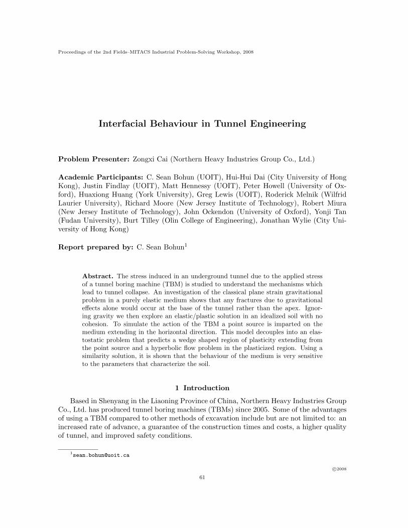
Figure 1 Front assembly of a TBM illustrating the excavation face, the pressurized spaceand the mechanism for the controlled removal of debris.
Figure 1 shows the operation of a tunnel boring machine. Typically the machine operatesbetween 4 and 80 m below the surface and extends approximately 400 m in length and18 m in diameter. Progress of the machine (the mucking speed) is quite slow at about500 m/month and to stabilize the excavation face, a pressure is applied and removal of theexcavated material is controlled as shown by the screw gear in the figure. The objective forthe control is to ensure that any surface displacements are between 1 and 3 cm.
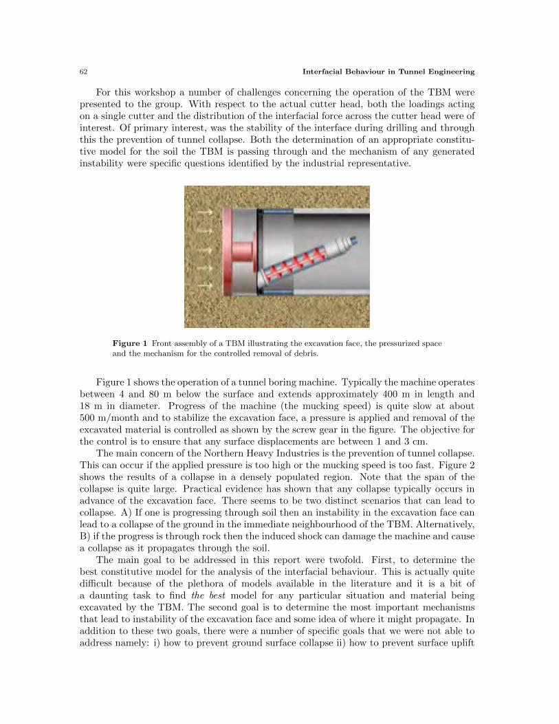
The main concern of the Northern Heavy Industries is the prevention of tunnel collapse.This can occur if the applied pressure is too high or the mucking speed is too fast. Figure 2shows the results of a collapse in a densely populated region. Note that the span of thecollapse is quite large. Practical evidence has shown that any collapse typically occurs inadvance of the excavation face. There seems to be two distinct scenarios that can lead tocollapse. A) If one is progressing through soil then an instability in the excavation face canlead to a collapse of the ground in the immediate neighbourhood of the TBM. Alternatively,B) if the progress is through rock then the induced shock can damage the machine and causea collapse as it propagates through the soil.
The main goal to be addressed in this report were twofold. First, to determine thebest constitutive model for the analysis of the interfacial behaviour. This is actually quitedifficult because of the plethora of models available in the literature and it is a bit ofa daunting task to find the best model for any particular situation and material beingexcavated by the TBM. The second goal is to determine the most important mechanismsthat lead to instability of the excavation face and some idea of where it might propagate. Inaddition to these two goals, there were a number of specific goals that we were not able toaddress namely: i) how to prevent ground surface collapse ii) how to prevent surface uplift
Interfacial Behaviour in Tunnel Engineering 63
Figure 2 Results of a tunnel collapse in a residential area showing the possibly very large extent.
iii) determination of loadings on a single cutter and iv) the distribution of the forces on thecutter head.
2 The Effect of Gravity
The TBM works by shearing away soil and rock and continually moving forward intothe newly created space. To keep the soil matrix in place while it is being destabilized, themachine applies a pressure on the order of 2 MPa to the cutting face. As shards of materialloosen from the main body they are churned up to create a region of plasticity in front ofthe machine and it is the behaviour of this region that determines the reaction of the soilto the drilling. Moving away from the cutting head, one expects that the soil would movefrom this plastic state to a region of relative elasticity. Depending upon the the materialbeing drilled, the size of this plastic region can vary in thickness. There are a number offundamental processes involved in the creation of a tunnel and understanding the balancebetween them is the key to preventing tunnel collapse during its creation. These processesare i) the loading pressure that moves the TBM forward into the newly created region; ii)the shear stress applied to the soil matrix used to grind up the material and remove it; andiii) the hydrostatic pressure on the soil due to the soil surrounding the tunnel. This firstsection looks at the gravitational effects.
We are primarily interested in determining the extent of the region of plasticity fromthe drill and how the soil moves within it as the drill moves through the soil. Due tothe complexity of this problem we will ignore the effect of gravity in the sequel, but itis informative to see it’s effect by first reviewing a classical [3] problem. That is, thedetermination of the stress in the elastic medium surrounding a tunnel of radius a at adepth of H.
In the plane strain case the displacement u = (u(r, θ), v(r, θ), 0), and one is led to solvethe momentum balance system
1
r
∂
∂r(rσrr) +
1
r
∂
∂θσrθ −
1
rσθθ − ρg sin θ = 0, σrr(a) = 0, (2.1a)
1
r
∂
∂r(rσrθ) +
1
r
∂
∂θσθθ +
1
rσrθ − ρg cos θ = 0, σrθ(a) = 0, (2.1b)
64 Interfacial Behaviour in Tunnel Engineering
where we have imposed a zero-traction condition on the tunnel wall. Note that in thisplane strain limit σzz = ν(σrr +σθθ). Finding a solution is more complicated in a multiply-connected domain, but can be resolved by constructing a modified Airy stress functionand considering the case a � H so that in the far-field limit (r → ∞) one obtains thehydrostatic solution σrr = σθθ = ρg(r sin θ −H), σrθ = 0. The resulting components of thestress tensor are [2]
σrr = ρg
(1− a2
r2
)(−H +
(1 +
(1− 2ν)
4(1− ν)
a2
r2
)r sin θ
), (2.2a)
σrθ = −ρga2 (1− 2ν)
4(1− ν)
(1− a2
r2
)cos θ
r, (2.2b)
σθθ = ρg
(1 +
a2
r2
)(−H +
(1− 2ν)
4(1− ν)
a2 sin θ
r
)+ ρgr sin θ, (2.2c)
σzz = 2νρg
(−H +
(1 +
1
4(1− ν)
a2
r2
)r sin θ
). (2.2d)
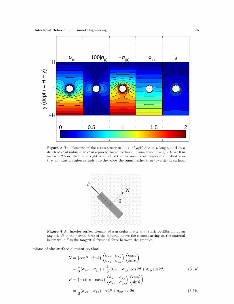
These components are shown in Figure 3 along with the maximum shear stress given by
S = maxi,j
1
2|σi − σj | (2.3)
where the σi represent the eigenvalues of the stress tensor. The so-called Tresca criterionproposes that the material will yield and become plastic once S exceed some critical valueσY . What is clear from the form of the solution is that by treating the material aroundthe tunnel as an elastic solid, any plastic region in a neighbourhood of the tunnel extendsinto the earth below the tunnel rather than upwards towards the surface. It is this upwardspropagation of a plasticized region of earth that is suspected to lead to tunnel collapse.
Within the elastic region the Navier equations are supplemented with the constitutiverelationship the connects the stresses and strains in the material and an appropriate set ofboundary conditions. The material remains elastic provided S < σY as discussed above.Once the material becomes plastic then the simplest model is to simply replace the constitu-tive relationship with the possibly nonlinear condition S = σY . The free boundary betweenthe elastic and plastic regions being determined by imposing a continuity condition. See [2]for an in depth discussion of these aspects.
3 Yield Criterion for Soils
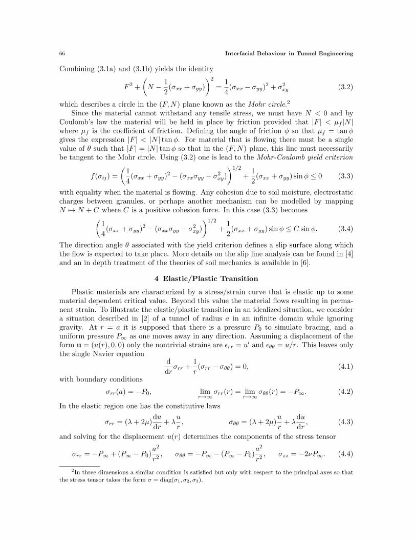
The mechanical properties of soil vary greatly depending upon the nature of a givensample. At one end of the spectrum is dry sand, with no cohesive bond between theindividual particles, to that of plastic clay with strong bonds holding the clay particlestogether. To develop an expression for the yield criterion, we consider a two-dimensionalsample of dry granular material that is in static equilibrium as shown in Figure 4.
Acting on this surface are a normal traction N and frictional stress F . These areobtained from the stress tensor by taking the corresponding component of the stress in the
Interfacial Behaviour in Tunnel Engineering 65
−σrr 100|σ
rθ| −σθθ−σ
zz S
y (d
epth
= H
− y
)
−H
0
H
0 0.5 1 1.5 2
Figure 3 The elements of the stress tensor in units of ρgH due to a long tunnel at adepth of H of radius a� H in a purely elastic medium. In simulation ν = 1/3, H = 20 mand a = 2.5 m. To the far right is a plot of the maximum shear stress S and illustratesthat any plastic region extends into the below the tunnel rather than towards the surface.
θ
NF
Figure 4 An interior surface element of a granular material in static equilibrium at anangle θ. N is the normal force of the material above the element acting on the materialbelow while F is the tangential frictional force between the granules.
plane of the surface element so that
N =(cos θ sin θ
)(σxx σxyσxy σyy
)(cos θsin θ
)=
1
2(σxx + σyy) +
1
2(σxx − σyy) cos 2θ + σxy sin 2θ, (3.1a)
F =(− sin θ cos θ
)(σxx σxyσxy σyy
)(cos θsin θ
)=
1
2(σyy − σxx) sin 2θ + σxy cos 2θ. (3.1b)
66 Interfacial Behaviour in Tunnel Engineering
Combining (3.1a) and (3.1b) yields the identity
F 2 +
(N − 1
2(σxx + σyy)
)2
=1
4(σxx − σyy)2 + σ2xy (3.2)
which describes a circle in the (F,N) plane known as the Mohr circle.2
Since the material cannot withstand any tensile stress, we must have N < 0 and byCoulomb’s law the material will be held in place by friction provided that |F | < µf |N |where µf is the coefficient of friction. Defining the angle of friction φ so that µf = tanφgives the expression |F | < |N | tanφ. For material that is flowing there must be a singlevalue of θ such that |F | = |N | tanφ so that in the (F,N) plane, this line must necessarilybe tangent to the Mohr circle. Using (3.2) one is lead to the Mohr-Coulomb yield criterion
f(σij) =
(1
4(σxx + σyy)
2 − (σxxσyy − σ2xy))1/2
+1
2(σxx + σyy) sinφ ≤ 0 (3.3)
with equality when the material is flowing. Any cohesion due to soil moisture, electrostaticcharges between granules, or perhaps another mechanism can be modelled by mappingN 7→ N + C where C is a positive cohesion force. In this case (3.3) becomes(
1
4(σxx + σyy)
2 − (σxxσyy − σ2xy))1/2
+1
2(σxx + σyy) sinφ ≤ C sinφ. (3.4)
The direction angle θ associated with the yield criterion defines a slip surface along whichthe flow is expected to take place. More details on the slip line analysis can be found in [4]and an in depth treatment of the theories of soil mechanics is available in [6].
4 Elastic/Plastic Transition
Plastic materials are characterized by a stress/strain curve that is elastic up to somematerial dependent critical value. Beyond this value the material flows resulting in perma-nent strain. To illustrate the elastic/plastic transition in an idealized situation, we considera situation described in [2] of a tunnel of radius a in an infinite domain while ignoringgravity. At r = a it is supposed that there is a pressure P0 to simulate bracing, and auniform pressure P∞ as one moves away in any direction. Assuming a displacement of theform u = (u(r), 0, 0) only the nontrivial strains are εrr = u′ and εθθ = u/r. This leaves onlythe single Navier equation
d
drσrr +
1
r(σrr − σθθ) = 0, (4.1)
with boundary conditions
σrr(a) = −P0, limr→∞
σrr(r) = limr→∞
σθθ(r) = −P∞. (4.2)
In the elastic region one has the constitutive laws
σrr = (λ+ 2µ)du
dr+ λ
u
r, σθθ = (λ+ 2µ)
u
r+ λ
du
dr, (4.3)
and solving for the displacement u(r) determines the components of the stress tensor
σrr = −P∞ + (P∞ − P0)a2
r2, σθθ = −P∞ − (P∞ − P0)
a2
r2, σzz = −2νP∞. (4.4)
2In three dimensions a similar condition is satisfied but only with respect to the principal axes so thatthe stress tensor takes the form σ = diag(σ1, σ2, σ3).
Interfacial Behaviour in Tunnel Engineering 67
In this case the yield criterion (3.3) is
f(σij) =
(1
4(σrr + σθθ)
2 − (σrrσθθ − σ2rθ))1/2
+1
2(σrr + σθθ) sinφ = 0 (4.5)
which simplifies to σθθ = kσrr where the triaxial stress factor k satisfies
k =1 + sinφ
1− sinφ. (4.6)
Looking at the ratio σθθ/σrr at r = a we see that the material remains elastic provided thatthe bracing pressure P0 does not fall below the critical value
Pcrit =2
k + 1P∞. (4.7)
Below this critical pressure a plastic region extends from the tunnel wall at r = a to a valueof r = s within which the stress components satisfy
d
drσrr +
1
r(σrr − σθθ) = 0, σθθ = kσrr, σrr(a) = −P0 > −Pcrit (4.8)
with solution
σrr = −P0
(ra
)k−1, σθθ = −kP0
(ra
)k−1, σzz = −2νP∞
P0
Pcrit
(ra
)k−1. (4.9)
Taking (4.4), (4.7) and (4.9) together gives the composite elastic-plastic solution
σrr =
−P0
(ra
)k−1, a ≤ r ≤ s, P0 < Pcrit,
−P∞ + P∞
(k−1k+1
) s2r2, r > s, P0 < Pcrit,
−P∞ + (P∞ − P0)a2
r2, r ≥ a, P0 ≥ Pcrit,
(4.10a)
σθθ =
−kP0
(ra
)k−1, a ≤ r ≤ s, P0 < Pcrit,
−P∞ − P∞(k−1k+1
) s2r2, r > s P0 < Pcrit,
−P∞ − (P∞ − P0)a2
r2, r ≥ a, P0 ≥ Pcrit.
(4.10b)
To find the location s we impose that σrr is continuous as r = s for P0 < Pcrit which givesthe expression for
s = a
(Pcrit
P0
)1/(k−1). (4.11)
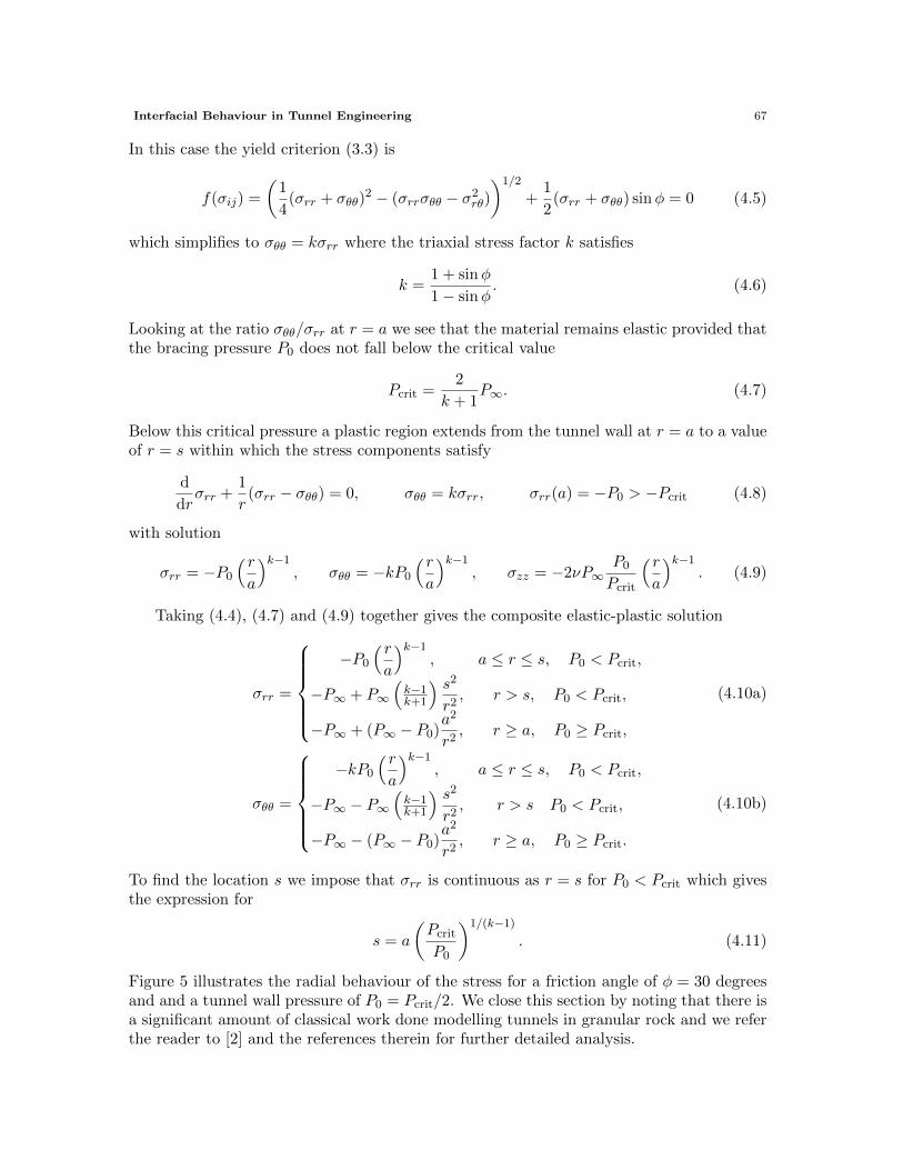
Figure 5 illustrates the radial behaviour of the stress for a friction angle of φ = 30 degreesand and a tunnel wall pressure of P0 = Pcrit/2. We close this section by noting that there isa significant amount of classical work done modelling tunnels in granular rock and we referthe reader to [2] and the references therein for further detailed analysis.
68 Interfacial Behaviour in Tunnel Engineering
r/a
σ ij/P∞ σ
rr/P∞
σθθ/P∞
Plastic Elastic
P0 = 0.5 P
crit, φ = 30 degrees
1 s/a 2s/a−2k/(k+1)
−1
−k/(k+1)
−2/(k+1)
−1/(k+1)
Figure 5 The radial and hoop stress in the material surrounding a tunnel of radius awhen the pressure at the tunnel wall is P0 = Pcrit/2. In this example the angle if frictionis taken to be 30 degrees so that the triaxial stress factor k = 3 and Pcrit = P∞/2.
5 The Model
What we would like to understand with respect to the operation of the TBM is thedynamics of any plasticized region extending from the tunnel to perhaps the surface. Theequations of plasticity must include a form of momentum balance, a yield criterion andsome form of associated flow rule. The flow v associated with a displacement u is given by
v =∂u
∂t+ (v · ∇)u (5.1)
or solving for v explicitly,
v =(I −∇uT
)−1 ∂u
∂t' ∂u
∂t(5.2)
for small displacements. The Cauchy equation is similarly modified to
∇ · σ + ρg = ρ
(∂v
∂t+ (v · ∇)v
)' 0 (5.3)
by neglecting any accelerations in the flow. A flow rule associated with the yield criterionf(σij) = 0 can be arrived at by considering the heat dissipated during a deformation, andmaximizing the rate at which heat is dissipated. As shown in [2], the heat dissipated during
Interfacial Behaviour in Tunnel Engineering 69
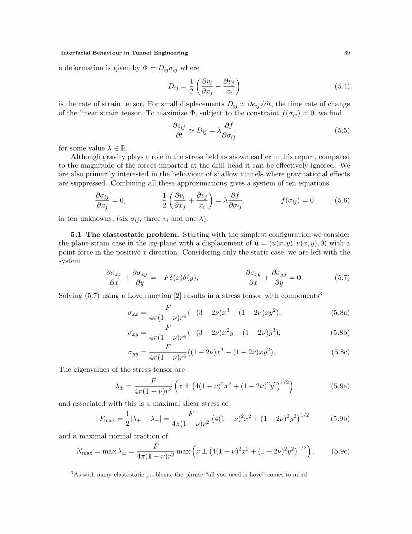
a deformation is given by Φ = Dijσij where
Dij =1
2
(∂vi∂xj
+∂vjxi
)(5.4)
is the rate of strain tensor. For small displacements Dij ' ∂eij/∂t, the time rate of changeof the linear strain tensor. To maximize Φ, subject to the constraint f(σij) = 0, we find
∂eij∂t' Dij = λ
∂f
∂σij(5.5)
for some value λ ∈ R.Although gravity plays a role in the stress field as shown earlier in this report, compared
to the magnitude of the forces imparted at the drill head it can be effectively ignored. Weare also primarily interested in the behaviour of shallow tunnels where gravitational effectsare suppressed. Combining all these approximations gives a system of ten equations
∂σij∂xj
= 0,1
2
(∂vi∂xj
+∂vjxi
)= λ
∂f
∂σij, f(σij) = 0 (5.6)
in ten unknowns; (six σij , three vi and one λ).
5.1 The elastostatic problem. Starting with the simplest configuration we considerthe plane strain case in the xy-plane with a displacement of u = (u(x, y), v(x, y), 0) with apoint force in the positive x direction. Considering only the static case, we are left with thesystem
∂σxx∂x
+∂σxy∂y
= −Fδ(x)δ(y),∂σxy∂x
+∂σyy∂y
= 0. (5.7)
Solving (5.7) using a Love function [2] results in a stress tensor with components3
σxx =F
4π(1− ν)r4(−(3− 2ν)x3 − (1− 2ν)xy2), (5.8a)
σxy =F
4π(1− ν)r4(−(3− 2ν)x2y − (1− 2ν)y3), (5.8b)
σyy =F
4π(1− ν)r4((1− 2ν)x3 − (1 + 2ν)xy2). (5.8c)
The eigenvalues of the stress tensor are
λ± =F
4π(1− ν)r2
(x±
(4(1− ν)2x2 + (1− 2ν)2y2
)1/2)(5.9a)
and associated with this is a maximal shear stress of
Fmax =1
2|λ+ − λ−| =
F
4π(1− ν)r2(4(1− ν)2x2 + (1− 2ν)2y2
)1/2(5.9b)
and a maximal normal traction of
Nmax = maxλ± =F
4π(1− ν)r2max
(x±
(4(1− ν)2x2 + (1− 2ν)2y2
)1/2). (5.9c)
3As with many elastostatic problems, the phrase “all you need is Love” comes to mind.
70 Interfacial Behaviour in Tunnel Engineering
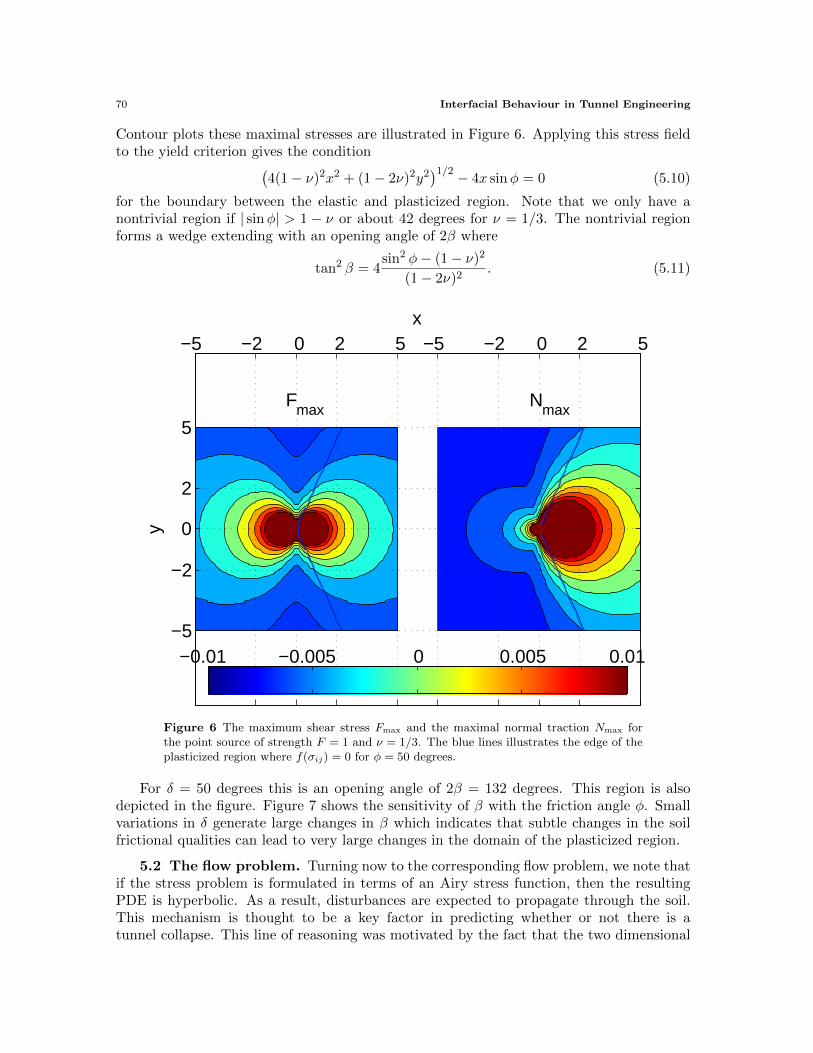
Contour plots these maximal stresses are illustrated in Figure 6. Applying this stress fieldto the yield criterion gives the condition(
4(1− ν)2x2 + (1− 2ν)2y2)1/2 − 4x sinφ = 0 (5.10)
for the boundary between the elastic and plasticized region. Note that we only have anontrivial region if | sinφ| > 1 − ν or about 42 degrees for ν = 1/3. The nontrivial regionforms a wedge extending with an opening angle of 2β where
tan2 β = 4sin2 φ− (1− ν)2
(1− 2ν)2. (5.11)
x
y
Fmax
Nmax
−5 −2 0 2 5 −5 −2 0 2 5
−5
−2
0
2
5
−0.01 −0.005 0 0.005 0.01
Figure 6 The maximum shear stress Fmax and the maximal normal traction Nmax forthe point source of strength F = 1 and ν = 1/3. The blue lines illustrates the edge of theplasticized region where f(σij) = 0 for φ = 50 degrees.
For δ = 50 degrees this is an opening angle of 2β = 132 degrees. This region is alsodepicted in the figure. Figure 7 shows the sensitivity of β with the friction angle φ. Smallvariations in δ generate large changes in β which indicates that subtle changes in the soilfrictional qualities can lead to very large changes in the domain of the plasticized region.
5.2 The flow problem. Turning now to the corresponding flow problem, we note thatif the stress problem is formulated in terms of an Airy stress function, then the resultingPDE is hyperbolic. As a result, disturbances are expected to propagate through the soil.This mechanism is thought to be a key factor in predicting whether or not there is atunnel collapse. This line of reasoning was motivated by the fact that the two dimensional

Interfacial Behaviour in Tunnel Engineering 71
φ (degrees)
β (d
egre
es)
40 50 60 70 80 900
10
20
30
40
50
60
70
80
Figure 7 Dependence of one-half the opening angle, β, with respect to the friction angleφ according to (5.11) for ν = 1/3.
problem can be written as a hyperbolic system in the variables p = −(σxx + σyy)/2 andtan 2ψ = 2σxy/(σxx − σyy) with corresponding characteristics
λ± = tan
(ψ +
π
2±(π
4+φ
2
))(5.12)
and Riemann invariants
R± = 2ψ ± cotφ log p. (5.13)
See [1, 5] for a direction application of this to the flow of granular material in a grain hopper.Returning to the (5.6) we have the momentum balance,
∂σrr∂r
+1
r
∂σrθ∂θ
+σrr − σθθ
r= 0, (5.14a)
∂σrθ∂r
+1
r
∂σθθ∂θ
+2σrθr
= 0, (5.14b)
the equation of state for the plasticized region (4.5) and three expressions defining the flowv = (vr, vθ)
∂vr∂r
= λ∂f
∂σrr,
1
r
∂vr∂θ
+∂vθ∂r− vθ
r= 2λ
∂f
∂σrθ,
1
r
(∂vθ∂θ
+ vr
)= λ
∂f
∂σrr. (5.14c)
The elastic solution (5.8) is consistent with an isotropic elastic medium so it is not applicablefor this plasticized situation. However, if we suppose that the tunnel is deep enough so thatthere are no boundary effects, then we can search for a similarity solution. Motivated bythe solution (5.8) we choose4 σθθ = A cos θ/r and the momentum equations are satisfied
4σθθ = σyy cos2 θ + σxx sin2 θ + 2σxy cos θ sin θ.
72 Interfacial Behaviour in Tunnel Engineering
provided
σθθ =A cos θ
r, σrθ =
A sin θ
r, σrr =
Ag(θ)
r(5.15)
for any function g(θ). The form of g(θ) is chosen to ensure that the stress field is consistentwith the yield surface (4.5) and one can verify that
g(θ) = (2 sec2 φ− 1) cos θ + sec2 φ (2(cos 2θ − cos 2φ))1/2 (5.16)
accomplishes this. Using these expressions for the stress a similarity solution for the flowtakes the form
λ = γ(θ)rα−1, vr = wr(θ)rα, vθ = wθ(θ)r
α (5.17)
and transforms the flow rule into the nonstandard eigenvalue problem for the plasticizedregion −δ < θ < δ
d
dθ
(wrwθ
)=
2αfrθfrr
−ααfθθfrr− 1 0
(wrwθ),
(wrwθ
)(±δ) = 0, (5.18)
where fij = ∂f/∂σij and the boundary condition at θ = ±δ enforces a no-flow conditionwhere g becomes complex valued.
6 Results
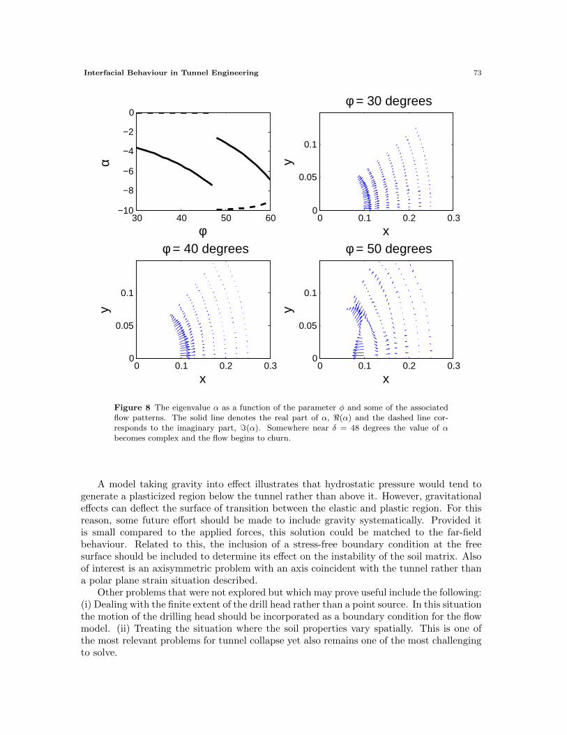
The flow problem was solved numerically for a range of friction angles. In particular,φ = 30, 40 and 50 degrees and displayed in Figure 8. Note that the point source solutionis not a similarity solution and some care must be taken when comparing the elastostaticproblem with the solution of the flow problem. What is clear is that as δ is increased,the displacement becomes larger at the source of the disturbance and increasingly local-ized. Eventually a critical value of φ is reached and α becomes complex which results ina churning flow where material is forced from the outer edges back towards the drill head.This sets up instabilities in the soil matrix that propagate a significant distance from thehead of the drill. It is suspected that this phenomenon could be one responsible for thecollapse. It is encouraging that this bifurcation occurs somewhere near δ = 48 degrees withsimulations using ν = 1/3 and that the opening angle of the plasticized region increaseswith δ comparable with that predicted by the elastostatic point source case.
7 Conclusions and Future Work
Working in a simplified geometry the tunnel collapse problem was decoupled into anelastostatic point source stress field and a flow model for the plasticized region that max-imizes heat dissipation in the media. This latter model leads to a hyperbolic equation forthe flow velocity whose behaviour is highly sensitive to the soil parameters.
What has been made quite clear, by studying these geometrically simplified problems,is that understanding the material properties of the soil prior to tunnelling is a key topreventing collapse. The extent of the plasticized region depends strongly on this behaviouryet saturates quickly in extreme cases. This latter fact lends itself to the possibility ofpredicting a minimal depth that the TBM would have to operate to ensure no collapseoccurs in a given worst case scenario.
Interfacial Behaviour in Tunnel Engineering 73
30 40 50 60−10
−8
−6
−4
−2
0α
φ0 0.1 0.2 0.3
0
0.05
0.1
x
y
φ = 30 degrees
0 0.1 0.2 0.30
0.05
0.1
x
y
φ = 40 degrees
0 0.1 0.2 0.30
0.05
0.1
x
y
φ = 50 degrees
Figure 8 The eigenvalue α as a function of the parameter φ and some of the associatedflow patterns. The solid line denotes the real part of α, <(α) and the dashed line cor-responds to the imaginary part, =(α). Somewhere near δ = 48 degrees the value of αbecomes complex and the flow begins to churn.
A model taking gravity into effect illustrates that hydrostatic pressure would tend togenerate a plasticized region below the tunnel rather than above it. However, gravitationaleffects can deflect the surface of transition between the elastic and plastic region. For thisreason, some future effort should be made to include gravity systematically. Provided itis small compared to the applied forces, this solution could be matched to the far-fieldbehaviour. Related to this, the inclusion of a stress-free boundary condition at the freesurface should be included to determine its effect on the instability of the soil matrix. Alsoof interest is an axisymmetric problem with an axis coincident with the tunnel rather thana polar plane strain situation described.
Other problems that were not explored but which may prove useful include the following:(i) Dealing with the finite extent of the drill head rather than a point source. In this situationthe motion of the drilling head should be incorporated as a boundary condition for the flowmodel. (ii) Treating the situation where the soil properties vary spatially. This is one ofthe most relevant problems for tunnel collapse yet also remains one of the most challengingto solve.
74 Interfacial Behaviour in Tunnel Engineering
Acknowledments
The author would like to thank Greg Lewis for his infinite patience in waiting for thisreport. I’m not sure I would have been as lenient with such a long delay. In closing, I wouldlike to remark that in the final weeks of preparation of this material, a TBM in NiagaraFalls Ont. completed digging a massive tunnel under the falls itself. The 30 tonne TBMknown as “Big Becky” started in 2006 and completed the 10.2 kilometre tunnel, 90 m to140 m in depth, as part of the construction of a hydroelectric infrastructure project in theNiagara region. This tunnel is roughly 150% larger than the Chunnel linking England andFrance under the English channel. Completing the report as this announcement was madewas prophetic.
References
[1] Brennan, C. & Pearce, J. (1978). Granular material flow in two-dimensional hoppers, Journal AppliedMechanics, American Society of Mechanical Engineers, 45, pp. 43-50.
[2] Howell, P., Kozyreff, G. & Ockendon, J. (2009). Applied Solid Mechanics, Cambridge Texts in AppliedMathematics.
[3] Mindlin, R.D. (1939). Stress distribution around a tunnel. Proceedings of the American Society of CivilEngineers, 65(4), pp. 619-642.
[4] Richards, R. (2001). Principles of Solid Mechanics, CRC Press LLC.[5] Tayler, A.B. (1986). Mathematical models in applied mechanics, Claringdon Press, Oxford.[6] Terzaghi, K. & Peck, R.B. (1948). Soil Mechanics in Engineering Practice, Wiley, New York.