interference challenges for industry communication kia
TRANSCRIPT

Interference challenges for industry communication
Kia Wiklundh, PhD
Wireless technology
• Simplifies many situations where
cables have been used
• Flexible
• Opens up for all kinds of control and
monitoring
• Devices and chips have become
cheaper
• Challenges:
- Shares the channel
- Sensitive to interference
- Demanding channel propagation
Qamcom Research & Technology Linköping2
Communcation requirements in industrial use cases
• Varying but often demanding requirements
• Differ significantly from public mobile broadband (MBB) services.
• Include Ultra-reliable and low latency communications (URLLC) with ultra-
high availability and resilience
Qamcom Research & Technology Linköping3
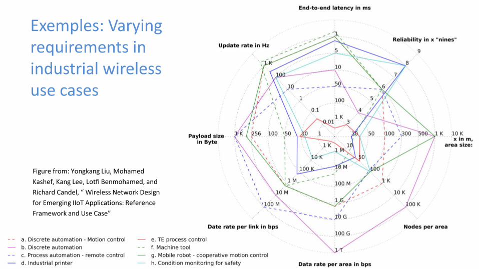
Exemples: Varying requirements in industrial wireless use cases
Figure from: Yongkang Liu, Mohamed
Kashef, Kang Lee, Lotfi Benmohamed, and
Richard Candel, “ Wireless Network Design
for Emerging IIoT Applications: Reference
Framework and Use Case”

Challenging environment
• Frequency bands
- Unlicensed versus Licensed Frequency Bands▪ Licensed frequency bands: a licensing fee for the exclusive right to transmit on assigned channels
within that band in a given geographic area◆ Typically 3GPP developed standards
▪ Unlicensed frequency bands: no permission to use, only requirement is to meet rules associated with the particular frequency band. Typically, the maximum transmission power is regulated
◆ Non-3GPP technologies
◆ Industrial, Scientific and Medical (ISM)◆ Challenge from an EMC point of view, especially for applications and services with
requirements on availability and non-disruptiveness, no guarantee for successful transmission
• Environment in combination with frequency
- Radio propagation▪ Difficult metal structures, obstacles => reflections▪ Other materials that might absorb the RF waves
• Interference environment in combination with frequency
Interference sources
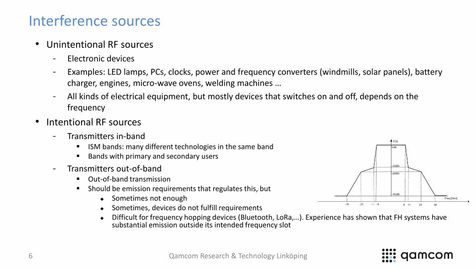
• Unintentional RF sources
- Electronic devices
- Examples: LED lamps, PCs, clocks, power and frequency converters (windmills, solar panels), batterycharger, engines, micro-wave ovens, welding machines …
- All kinds of electrical equipment, but mostly devices that switches on and off, depends on the frequency
• Intentional RF sources
- Transmitters in-band▪ ISM bands: many different technologies in the same band▪ Bands with primary and secondary users
- Transmitters out-of-band▪ Out-of-band transmission▪ Should be emission requirements that regulates this, but
◆ Sometimes not enough◆ Sometimes, devices do not fulfill requirements◆ Difficult for frequency hopping devices (Bluetooth, LoRa,…). Experience has shown that FH systems have
substantial emission outside its intended frequency slot
Qamcom Research & Technology Linköping6
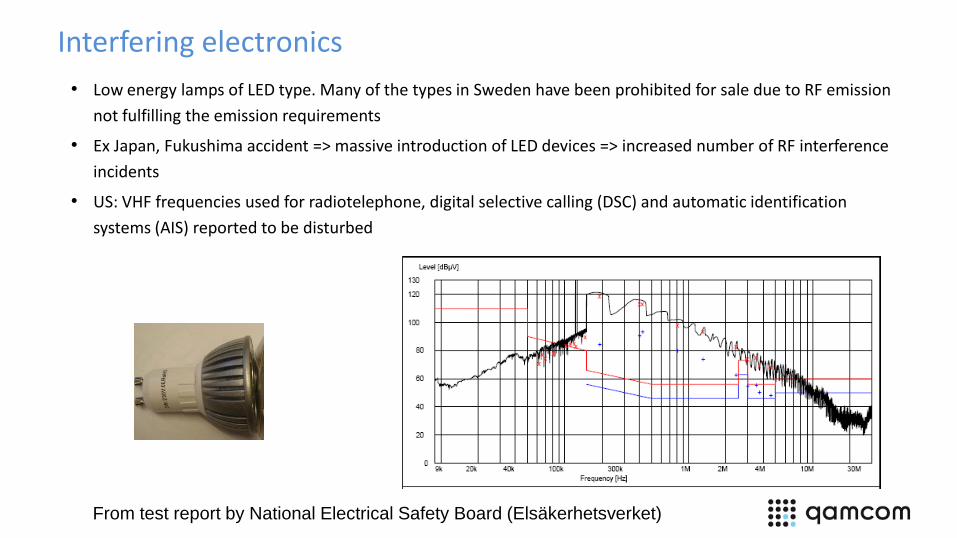
Interfering electronics
• Low energy lamps of LED type. Many of the types in Sweden have been prohibited for sale due to RF emission
not fulfilling the emission requirements
• Ex Japan, Fukushima accident => massive introduction of LED devices => increased number of RF interference
incidents
• US: VHF frequencies used for radiotelephone, digital selective calling (DSC) and automatic identification
systems (AIS) reported to be disturbed
From test report by National Electrical Safety Board (Elsäkerhetsverket)

Example of EMI from PC
• Results from [1]:The
noisiest area was by far the
CPU / SDRAM interface
with widespread harmonics
from the clock up into the
1-2 GHz region
Qamcom Research & Technology Linköping8
[1] Case Study: Poor PC Board Layout Causes Radiated EmissionsDecember 6, 2017 James Pawson, Interference technology
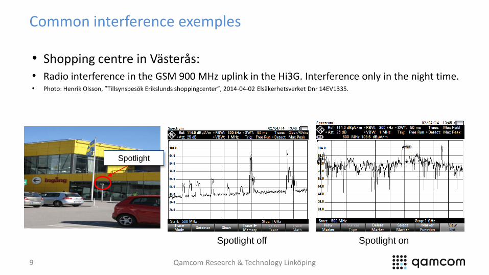
Common interference exemples
9
• Shopping centre in Västerås: • Radio interference in the GSM 900 MHz uplink in the Hi3G. Interference only in the night time. • Photo: Henrik Olsson, ”Tillsynsbesök Erikslunds shoppingcenter”, 2014-04-02 Elsäkerhetsverket Dnr 14EV1335.
Spotlight onSpotlight off
Spotlight
Qamcom Research & Technology Linköping
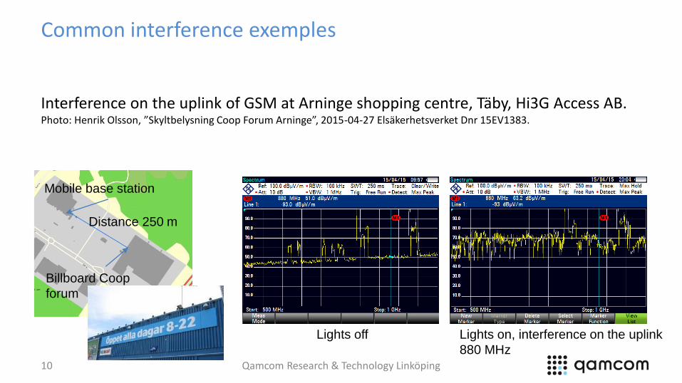
Common interference exemples
Qamcom Research & Technology Linköping10
Billboard Coop
forum
Mobile base station
Distance 250 m
Lights on, interference on the uplink
880 MHz
Interference on the uplink of GSM at Arninge shopping centre, Täby, Hi3G Access AB.Photo: Henrik Olsson, ”Skyltbelysning Coop Forum Arninge”, 2015-04-27 Elsäkerhetsverket Dnr 15EV1383.
Lights off

Interference environment
• Other factors that increases the risk for interference
- High levels
- Co-location of equipment and radio antennas
- Unfortunate frequency use/frequency planning
- Antenna placement
- Not fulfillment of requirements
- Large number of equipments
- ISM bands
▪ No coordinated use and many users (is increasing)
▪ Highly dynamic and unpredictable interference levels

Internet of Things
• Increasing amount of connected
devices, mainly due to IoT
• Forecasts
- Previously often 50 Billion year
2020From: Amy Nordrum, “Popular Internet of Things Forecast of 50 Billion Devices by 2020 Is Outdated”, IEEE Spectrum, Aug 2016
Forecast of total number of connected devices in the world
https://www.statista.com/statistics/471264/iot-number-of-
connected-devices-worldwide/
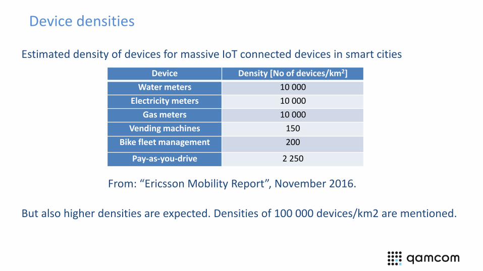
Device densities
Device Density [No of devices/km2]
Water meters 10 000
Electricity meters 10 000
Gas meters 10 000
Vending machines 150
Bike fleet management 200
Pay-as-you-drive 2 250
Estimated density of devices for massive IoT connected devices in smart cities
But also higher densities are expected. Densities of 100 000 devices/km2 are mentioned.
From: “Ericsson Mobility Report”, November 2016.
EMC Challenges
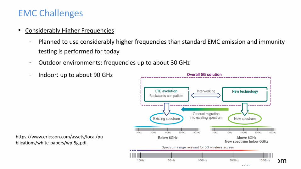
• Considerably Higher Frequencies
- Planned to use considerably higher frequencies than standard EMC emission and immunity
testing is performed for today
- Outdoor environments: frequencies up to about 30 GHz
- Indoor: up to about 90 GHz
https://www.ericsson.com/assets/local/publications/white-papers/wp-5g.pdf.
EMC Challenges
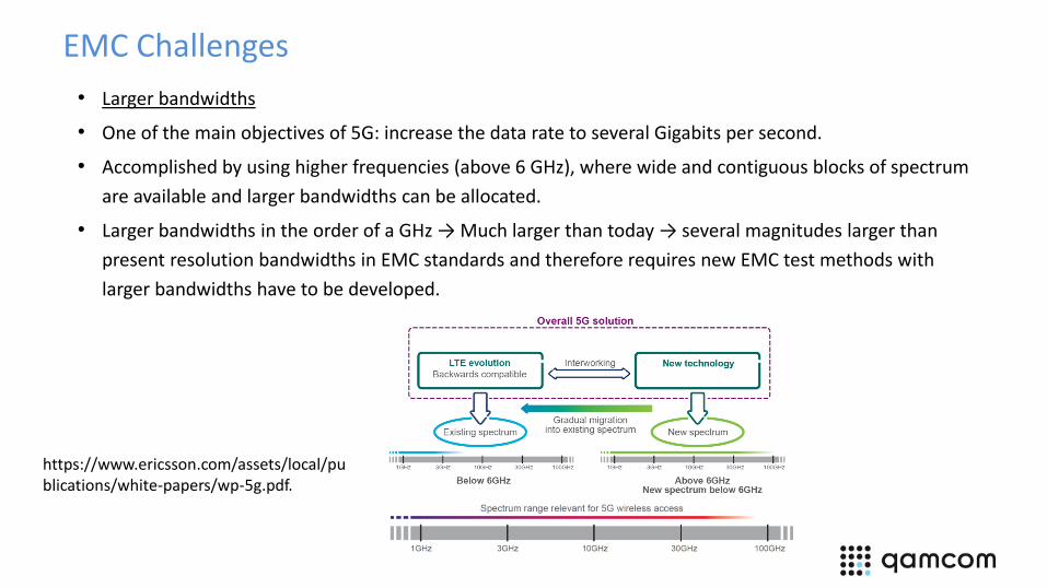
• Larger bandwidths
• One of the main objectives of 5G: increase the data rate to several Gigabits per second.
• Accomplished by using higher frequencies (above 6 GHz), where wide and contiguous blocks of spectrum
are available and larger bandwidths can be allocated.
• Larger bandwidths in the order of a GHz → Much larger than today → several magnitudes larger than
present resolution bandwidths in EMC standards and therefore requires new EMC test methods with
larger bandwidths have to be developed.
https://www.ericsson.com/assets/local/publications/white-papers/wp-5g.pdf.

Interference situation at higher frequencies?
• Lack of research of interference sources at higher frequencies
• Trend that electrical equipment radiates less at higher frequencies, but:
- For computers, the emission has during the last years got higher and higher in
frequency as clock frequencies has increased
- High speed equipments, as e.g. routers (12.5, 33 GHz), LAN switches with very
high clock frequencies (12.6 GHz), optical network terminals (10 GHz)=> RFI at
the adopted frequencies emitted from enclosure, cables, modulaes and PCB
layouts
• No emission requirements above 6 GHz
Qamcom Research & Technology Linköping16
Interference situation at higher frequencies?
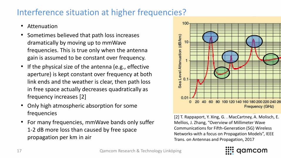
• Attenuation
• Sometimes believed that path loss increases dramatically by moving up to mmWavefrequencies. This is true only when the antenna gain is assumed to be constant over frequency.
• If the physical size of the antenna (e.g., effective aperture) is kept constant over frequency at both link ends and the weather is clear, then path loss in free space actually decreases quadratically as frequency increases [2]
• Only high atmospheric absorption for some frequencies
• For many frequencies, mmWave bands only suffer 1-2 dB more loss than caused by free space propagation per km in air
Qamcom Research & Technology Linköping17
[2] T. Rappaport, Y. Xing, G. . MacCartney, A. Molisch, E. Mellios, J. Zhang, “Overview of Millimeter Wave Communications for Fifth-Generation (5G) Wireless Networks-with a focus on Propagation Models”, IEEE Trans. on Antennas and Propagation, 2017
Interference situation at higher frequencies?
• Dominant interference source: Other transmitters, since the path loss is
not substantial (for LOS)
• Possible interference character in such interference environment:
- MIMO systems or directional antennas : small wavelength => possible with
many antennas => narrow lobes => On- and off character
- Restrictions on duty cycle or occasional transmissions
▪ Pulsed character or impulsive distribution
- Many interference sources, might get Normal distributed amplitude
probability
Qamcom Research & Technology Linköping18
EMC Challenges
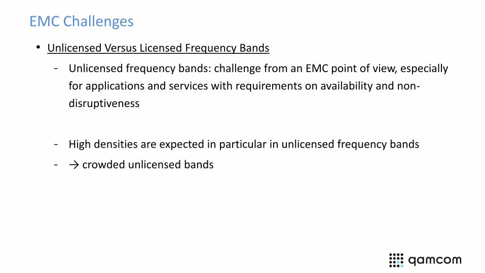
• Unlicensed Versus Licensed Frequency Bands
- Unlicensed frequency bands: challenge from an EMC point of view, especially
for applications and services with requirements on availability and non-
disruptiveness
- High densities are expected in particular in unlicensed frequency bands
- → crowded unlicensed bands
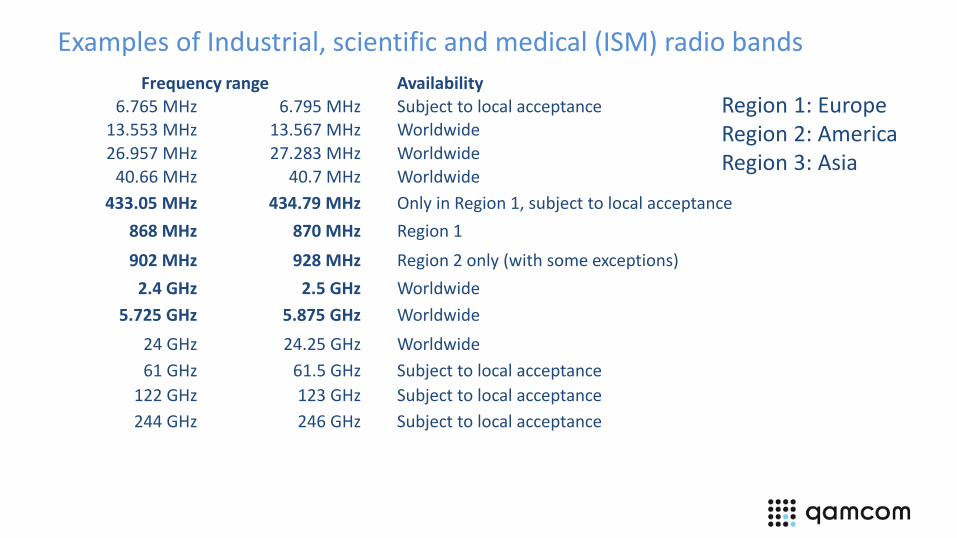
Examples of Industrial, scientific and medical (ISM) radio bands
Frequency range Availability6.765 MHz 6.795 MHz Subject to local acceptance
13.553 MHz 13.567 MHz Worldwide
26.957 MHz 27.283 MHz Worldwide
40.66 MHz 40.7 MHz Worldwide
433.05 MHz 434.79 MHz Only in Region 1, subject to local acceptance
868 MHz 870 MHz Region 1
902 MHz 928 MHz Region 2 only (with some exceptions)
2.4 GHz 2.5 GHz Worldwide
5.725 GHz 5.875 GHz Worldwide
24 GHz 24.25 GHz Worldwide
61 GHz 61.5 GHz Subject to local acceptance
122 GHz 123 GHz Subject to local acceptance
244 GHz 246 GHz Subject to local acceptance
Region 1: EuropeRegion 2: AmericaRegion 3: Asia

Certain requirements for use of unlicensed bands
• Type of service
• Transmit power
• Duty cycle
• Listen-before-transmit
• Spectrum properties
• Dynamic frequency selection (DFS)
- WiFi: Function to detect radar systems. If radar system is present, abort
transmission
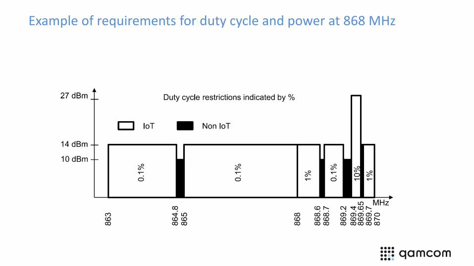
Example of requirements for duty cycle and power at 868 MHz
Communications principles in unlicensed bands
• Dynamic scheduling – devices compete about the resource
• CSMA – Carrier sense multiple access
- CSMA/CD - Collision Detection Carrier sensing and retransmissions
▪ Used in Ethernet IEEE 802.3
- CSMA/CA - Collision Avoidance
▪ RTS - Request To Send
▪ CTS - Clear To Send
▪ Used in WiFi IEEE 802.11 and IEEE 802.15.4
• Consequence of interference:
- delays
IEEE 802.15.4, technical standard, defines the operation of low-rate wireless personal area networks (LR-WPANs). Ex: ZigBee, WirelessHART, and Thread.
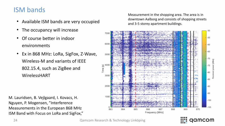
ISM bands
• Available ISM bands are very occupied
• The occupancy will increase
• Of course better in indoor
environments
• Ex in 868 MHz: LoRa, SigFox, Z-Wave,
Wireless-M and variants of IEEE
802.15.4, such as ZigBee and
WirelessHART
Qamcom Research & Technology Linköping24
Measurement in the shopping area. The area is in downtown Aalborg and consists of shopping streets and 3-5 storey apartment buildings.
M. Lauridsen, B. Vejlgaard, I. Kovacs, H. Nguyen, P. Mogensen, ”InterferenceMeasurements in the European 868 MHz ISM Band with Focus on LoRa and SigFox,”
EMC Challenges
• Increased interference level
- A large number of devices per area unit will give a higher level of the total
electromagnetic interference level
- Depend on transmit power, frequency use, duty cycle and density

Examples of the variety of duty cycles in IoT products
Duty cycle Application
0.0001 ”Leaf nodes” (low power networks)
0.001 LPWAN in ISM networks
0.01 LPWAN in ISM networks
0.1 Routers (low power networks)
1 Cordless microphones, cordless phones
ISM - Industrial, scientific and medical
Low Power Wide Area Network (LPWAN): low power wireless telecommunication wide area network designed to allow long range communications at a low bit rate among things (connected objects).

Increased EM Interference Levels
• Example:
• 10 000 and 200 000 devices per
square kilometer
• Duty factor 0.01 or 1
• Received interference power in
dBµW over an area of 100 m x 100 m
• Introduces an increase of the
background-noise level
Frequency Transmit power868 MHz 25 mW (44 dBµW)
5.8 GHz 200 mW (53 dBµW )
30 GHz 10 mW (40 dBµW)
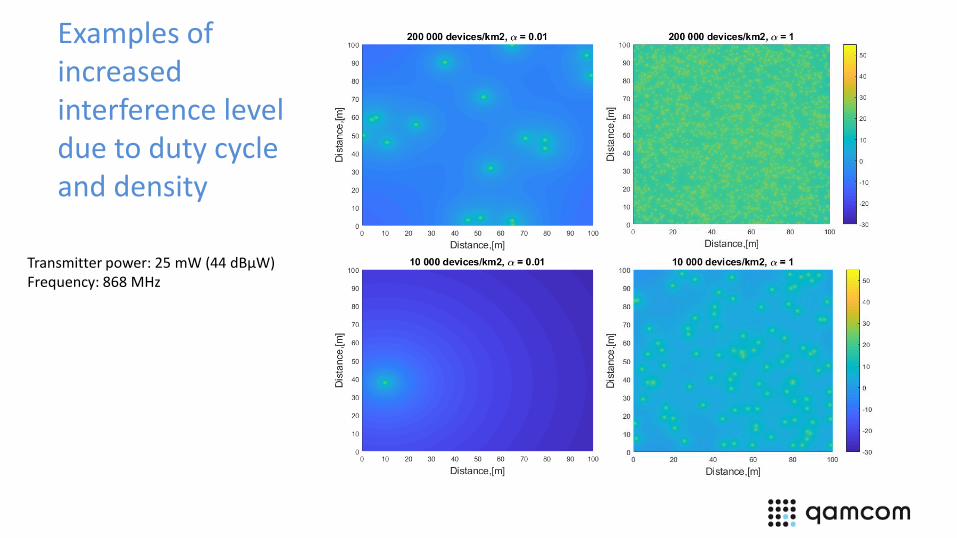
Examples of increased interference level due to duty cycle and density
Transmitter power: 25 mW (44 dBµW)Frequency: 868 MHz

Interference level
Transmitter power: 25 mW (44 dBµW)Frequency: 868 MHz

Consequences of interference
Depending on technology:
• Increased bit error probability (BEP) -> Lost packets- Disruptions/lower quality
- Decreased communication range, many times to a half or worse
- More vulnerable to other degrading phenomenon e.g. fading
- Decreased coverage/availability
• Lower data rate (for systems vid adaptive mod & coding)
• Delay of traffic (CSMA, ARQ)
• Less number of users (CDMA)

Consequences of interference
• Depends on the time character of the
interfering signal
- Statistical character and in time is
important
- E.g. impulsive interference will affect a
communicaiton reciver totally
diffferent than AWGN with same
average power
- => mesuring only average power (RMS)
is not enough when measuring the
interference environment
AWGN
More impulsiveness

Interference measurement
• RMS measurements do not reveal all information
Are these the worst?
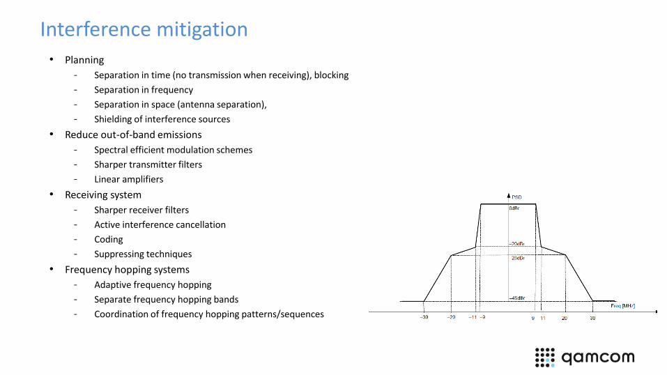
Interference mitigation• Planning
- Separation in time (no transmission when receiving), blocking
- Separation in frequency
- Separation in space (antenna separation),
- Shielding of interference sources
• Reduce out-of-band emissions
- Spectral efficient modulation schemes
- Sharper transmitter filters
- Linear amplifiers
• Receiving system
- Sharper receiver filters
- Active interference cancellation
- Coding
- Suppressing techniques
• Frequency hopping systems
- Adaptive frequency hopping
- Separate frequency hopping bands
- Coordination of frequency hopping patterns/sequences

Interference mitigation
• Interference measurements
• Diagnose systems
- Monitoring the EM environment, detection
and initiate counteractions
• Coverage measurements
• Prediction tools

Military technology
• WiFi solutions proposed for military use
• Critial communication
• Technology for on-line RF measurements/security threat analysis as part of the solution
• Aruba from Hewlett Packard Enterprise
- WiFi solution, based on IEEE 802.11ac, for US Army
- Scanning of the frequency band and classification of interference (ARUBAS RF protect module)
• Rajant
- The nodes contains radio equipment, supports IEEE 802.11a/b/g/n, to be used at 2,4 GHz and
5 GHz.
- Have a diagnostic processor to analyse the wireless network. Can monitor 900MHz, 2,4GHz
and 5,8GHz and different applications in the network.

Successful soultions
Situation
- High demands on the communication regarding reliability and delay
- ISM bands
- More occupied frequency bands
- Higher interference levels/more unpredictable interference situations
• More robust and reliable techniques against interference and to reduce delay
- Adapt to the situation: adaptive modulation and coding/link adaption, HARQ,
suppression/cancellation techniques
- MIMO techniques also as a robustness measure and pin-pointing the reciever
- Interference-aware systems with agile frequency usage
▪ Both commercial and military solutions
Qamcom Research & Technology Linköping36

Other solutions
• New innovative policies for frequency use
- Regulatory conditions – other types than lincensed and unlincensed bands,
maybe for certain areas?
▪ More effecient use of the frequency resources
- More ISM bands, or similar
▪ The current ones are crowded
Qamcom Research & Technology Linköping37

Conclusions
• Communication for industrial applications have very demanding and varying requirements
• Interference environment crucial
- No control of the interference environment => difficult to satisfy and assure the communication requirements
• Many future challenges:
- The increased use of wireless means higher interference levels due to larger concentration of co-located devices, and hence larger vulnerability to electromagnetic interference
- The considerable extension of frequency regions up to several tenths of GHz requires further development of methodology and equipment for standard EMC emission- and immunity testing
- The increase of wirelessly products will make the unlicensed frequency bands occupied to a considerably larger extent than today
- The co-location scenarios will be characterized by being highly dynamic, flexible and non-predictable. Therefore usage will to a larger extent have impact on the possibility of achieving EMC
- This development requires new technical solutions of the communication systems, frequency use, mitigation techniques and EMC standards

Questions?