N.T.S. UL DESIGN W-L-1077 SYSTEM NO. W-L-1077 N.T.S. UL DESIGN W-L-3004 SYSTEM NO. W-L-3004 SYSTEM NO. W-L-2081 N.T.S. UL DESIGN W-L-2081 SYSTEM NO. W-L-1054 N.T.S. UL DESIGN W-L-1054 N.T.S. UL DESIGN W-L-5028 SYSTEM NO. W-L-5028 TYP. RATED WALL TERMINATIONS N.T.S. N.T.S. JUNCTION BOX STUD WALL ELECTRICAL JUNCTION BOXES SHALLOW FIVE SIDE BOX DETAIL ADJACENT ELECTRICAL BOXES 1 - 2 - 3 - 4 - 5 - 7 - 6 - DRAWN BY SHEET SCALE DATE DESIGNED BY REVISIONS / DATE LAC MSB 07/25/16 AS SHOWN 16180.well PROJ. NO. 1975 Sansbury's Way West Palm Beach, FL 33411 Fax: (561) 493-4786 Phone: (561) 493-4787 Suite 108 Architecture, Inc. LCA AA 003432 AR 00015391 LESLAW A. CZACZYK AIA Advantone Florida, Inc. 855 SW 78th Ave. - Atrium "C" - Suite #202 Interior Improvement for Plantation, Florida 33324 A4.1 FIRE PROTECTION DETAILS
1. Wall assembly - The fire rated gypsum wallboard/stud wall assembly shall be constructed of the materials and in the manner described in the individual U300 or U400 Series Wall or Partition Designs in the UL Fire Resistance Directory and shall include the following construction features: A. Studs - Wall framing may consist of either wood studs or steel channel studs. Wood studs to consist of nom 2 by 4 in. lumber spaced 16 in. OC with nom 2 by 4 in. lumber end plates and cross braces. Steel studs to be min 3-5/8 in. wide by 1-3/8 in. deep channels spaced max 24 in. OC. B. Gypsum Board* - Two layers of nom 5/8 in. thick gypsum wallboard, as specified in the individual Wall and Partition Design. Max diam of opening cut in gypsum wallboard layers is 1-15/16 in. C. Fasteners - When wood stud framing is employed, gypsum wallboard attached to studs with cement coated nails as specified in the individual Wall or Partition Design. When steel channel stud framing is employed, gypsum wallboard attached to studs with Type S self-drilling, self-tapping bugle-head steel screws as specified in the individual Wall or Partition Design. Diam of circular through opening cut through both layers of gypsum wallboard on each side of wall assembly to be min 1/4 in. to max 11/16 in. larger than outside diam of flexible metal piping (Item 2) installed in through opening. Side edge of circular opening to be min 3 in. from nearest stud in wall cavity. 2. Through-Penetrating Product* - Flexible Metal Piping - Nom 1 in. diam (or smaller) steel Flexible Metal Piping. Max one flexible metal piping to be installed near center of circular opening in gypsum wallboard layers. Flexible metal piping to be rigidly supported on both sides of wall assembly. Plastic covering on piping shall be removed for a distance of 2 ft on both sides of wall assembly. GASTITE, DIV OF TITEFLEX 3. Fill, Void or Cavity Material* - Caulk - Caulk fill material forced into annular space around entire circumference of through penetrating product to completely fill nom 1-1/4 in. deep opening in gypsum wallboard layers on each side of the wall assembly. 3M COMPANY - CP 25WB+ *Bearing the UL Classification Mark
AutoCAD SHX Text
January 26, 1994 (Formerly System No. 188) F Rating - 2 Hr T Rating - 2 Hr
AutoCAD SHX Text
1. Wall Assembly - The fire-rated gypsum wallboard/stud wall assembly shall be constructed of the materials and in the manner specified in the individual U300 or U400 Series Wall and Partition Designs in the UL Fire Resistance Directory and shall include the following construction features: A. Studs - Wall framing may consist of either wood studs or steel channel studs. Wood studs to consist of nom 2 by 4 in. lumber spaced 16 in. OC. Steel studs to be min 2-1/2 in. wide and spaced max 24 in. OC. B. Gypsum Board* - Two layers of nom 5/8 in. thick gypsum wallboard, as specified in the individual Wall and Partition Design. Max diam of opening is 3 in. 2. Cables - Seven, 2/C No. 20 AWG (or smaller) cables with polyethylene insulation and polyvinyl jacket. Min separation between cables shall be 1/8 in. The annular space between cables and periphery of opening shall be 3/8 in. Cables to be rigidly supported on both sides of wall assembly. 3. Firestop System - The firestop system shall consist of the following: A. Metallic Sleeve - Nom 3 in. diam (or smaller) steel sleeve with nom 3/4 in. 3 in. long tabs to retain putty (Item C) in position. Sleeve fabricated from 0.016 in. thick galv sheet steel available from putty manufacturer. Length of steel sleeve to be equal to thickness of wall. Sleeve installed by coiling the sheet steel to a diam smaller than the through opening, inserting the coil through the opening and releasing the coil to let it uncoil against the circular cutouts in the wall assembly. As an alternate the steel sleeve may be field fabricated from 0.016 in. thick galv sheet steel in accordance with instruction sheet supplied by putty manufacturer. B. Packing Material - Min 3 in. thickness of min 6 pcf mineral wool batt insulation firmly packed into opening as a permanent form. Packing material to be recessed from both surfaces of wall as required to accommodate the required thickness of fill material. C. Fill, Void or Cavity Material* - Putty - Min 1 in. thickness of fill material applied within the annulus on both surfaces of wall. Putty to be forced into interstices of cable group to max extent possible. Additional fill material to be installed such that a min 1/8 in. crown is formed around the penetrating item. EGS NELSON FIRESTOP - Type FSP Putty *Bearing the UL Classification Mark
AutoCAD SHX Text
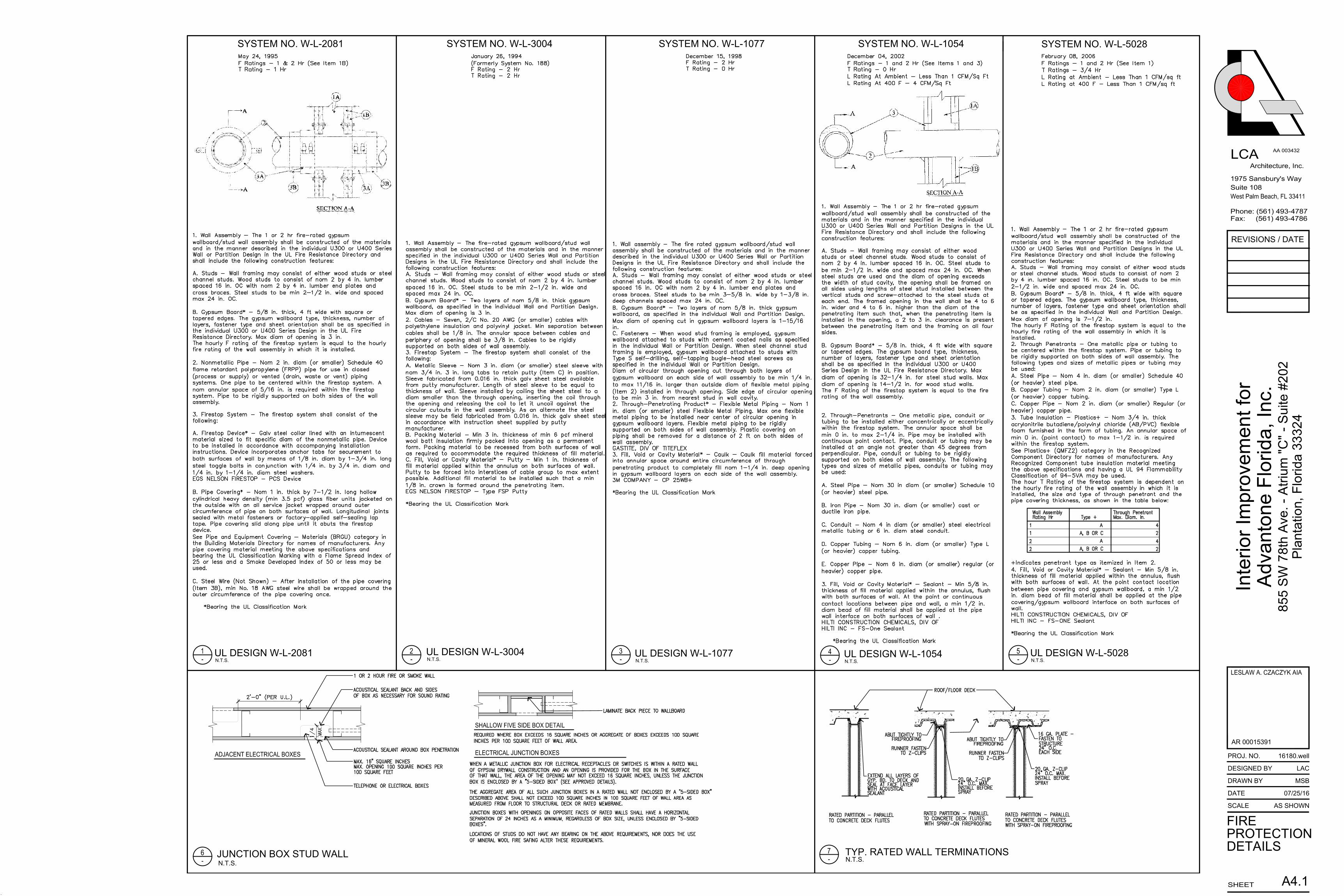
May 24, 1995 F Ratings - 1 & 2 Hr (See Item 1B) T Rating - 1 Hr
AutoCAD SHX Text
1. Wall Assembly - The 1 or 2 hr fire-rated gypsum wallboard/stud wall assembly shall be constructed of the materials and in the manner described in the individual U300 or U400 Series Wall or Partition Design in the UL Fire Resistance Directory and shall include the following construction features: A. Studs - Wall framing may consist of either wood studs or steel channel studs. Wood studs to consist of nom 2 by 4 in. lumber spaced 16 in. OC with nom 2 by 4 in. lumber end plates and cross braces. Steel studs to be min 2-1/2 in. wide and spaced max 24 in. OC. B. Gypsum Board* - 5/8 in. thick, 4 ft wide with square or tapered edges. The gypsum wallboard type, thickness, number of layers, fastener type and sheet orientation shall be as specified in the individual U300 or U400 Series Design in the UL Fire Resistance Directory. Max diam of opening is 3 in. The hourly F rating of the firestop system is equal to the hourly fire rating of the wall assembly in which it is installed. 2. Nonmetallic Pipe - Nom 2 in. diam (or smaller) Schedule 40 flame retardant polypropylene (FRPP) pipe for use in closed (process or supply) or vented (drain, waste or vent) piping systems. One pipe to be centered within the firestop system. A nom annular space of 5/16 in. is required within the firestop system. Pipe to be rigidly supported on both sides of the wall assembly. 3. Firestop System - The firestop system shall consist of the following: A. Firestop Device* - Galv steel collar lined with an intumescent material sized to fit specific diam of the nonmetallic pipe. Device to be installed in accordance with accompanying installation instructions. Device incorporates anchor tabs for securement to both surfaces of wall by means of 1/8 in. diam by 1-3/4 in. long steel toggle bolts in conjunction with 1/4 in. by 3/4 in. diam and 1/4 in. by 1-1/4 in. diam steel washers. EGS NELSON FIRESTOP - PCS Device B. Pipe Covering* - Nom 1 in. thick by 7-1/2 in. long hollow cylindrical heavy density (min 3.5 pcf) glass fiber units jacketed on the outside with an all service jacket wrapped around outer circumference of pipe on both surfaces of wall. Longitudinal joints sealed with metal fasteners or factory-applied self-sealing lap tape. Pipe covering slid along pipe until it abuts the firestop device. See Pipe and Equipment Covering - Materials (BRGU) category in the Building Materials Directory for names of manufacturers. Any pipe covering material meeting the above specifications and bearing the UL Classification Marking with a Flame Spread Index of 25 or less and a Smoke Developed Index of 50 or less may be used. C. Steel Wire (Not Shown) - After installation of the pipe covering (Item 3B), min No. 18 AWG steel wire shall be wrapped around the outer circumference of the pipe covering once. *Bearing the UL Classification Mark
AutoCAD SHX Text
December 04, 2002 F Ratings - 1 and 2 Hr (See Items 1 and 3) T Rating - 0 Hr L Rating At Ambient - Less Than 1 CFM/Sq Ft L Rating At 400 F - 4 CFM/Sq Ft
AutoCAD SHX Text
1. Wall Assembly - The 1 or 2 hr fire-rated gypsum wallboard/stud wall assembly shall be constructed of the materials and in the manner specified in the individual U300 or U400 Series Wall and Partition Designs in the UL Fire Resistance Directory and shall include the following construction features: A. Studs - Wall framing may consist of either wood studs or steel channel studs. Wood studs to consist of nom 2 by 4 in. lumber spaced 16 in. OC. Steel studs to be min 2-1/2 in. wide and spaced max 24 in. OC. When steel studs are used and the diam of opening exceeds the width of stud cavity, the opening shall be framed on all sides using lengths of steel stud installed between the vertical studs and screw-attached to the steel studs at each end. The framed opening in the wall shall be 4 to 6 in. wider and 4 to 6 in. higher than the diam of the penetrating item such that, when the penetrating item is installed in the opening, a 2 to 3 in. clearance is present between the penetrating item and the framing on all four sides. B. Gypsum Board* - 5/8 in. thick, 4 ft wide with square or tapered edges. The gypsum board type, thickness, number of layers, fastener type and sheet orientation shall be as specified in the individual U300 or U400 Series Design in the UL Fire Resistance Directory. Max diam of opening is 32-1/4 in. for steel stud walls. Max diam of opening is 14-1/2 in. for wood stud walls. The F Rating of the firestop system is equal to the fire rating of the wall assembly. 2. Through-Penetrants - One metallic pipe, conduit or tubing to be installed either concentrically or eccentrically within the firestop system. The annular space shall be min 0 in. to max 2-1/4 in. Pipe may be installed with continuous point contact. Pipe, conduit or tubing may be installed at an angle not greater than 45 degrees from perpendicular. Pipe, conduit or tubing to be rigidly supported on both sides of wall assembly. The following types and sizes of metallic pipes, conduits or tubing may be used: A. Steel Pipe - Nom 30 in diam (or smaller) Schedule 10 (or heavier) steel pipe. B. Iron Pipe - Nom 30 in. diam (or smaller) cast or ductile iron pipe. C. Conduit - Nom 4 in diam (or smaller) steel electrical metallic tubing or 6 in. diam steel conduit. D. Copper Tubing - Nom 6 in. diam (or smaller) Type L (or heavier) copper tubing. E. Copper Pipe - Nom 6 in. diam (or smaller) regular (or heavier) copper pipe. 3. Fill, Void or Cavity Material* - Sealant - Min 5/8 in. thickness of fill material applied within the annulus, flush with both surfaces of wall. At the point or continuous contact locations between pipe and wall, a min 1/2 in. diam bead of fill material shall be applied at the pipe wall interface on both surfaces of wall . HILTI CONSTRUCTION CHEMICALS, DIV OF HILTI INC - FS-One Sealant *Bearing the UL Classification Mark
AutoCAD SHX Text
February 08, 2006 F Ratings - 1 and 2 Hr (See Item 1) T Ratings - 3/4 Hr L Rating at Ambient - Less Than 1 CFM/sq ft L Rating at 400 F - Less Than 1 CFM/sq ft
AutoCAD SHX Text
1. Wall Assembly - The 1 or 2 hr fire-rated gypsum wallboard/stud wall assembly shall be constructed of the materials and in the manner specified in the individual U300 or U400 Series Wall and Partition Designs in the UL Fire Resistance Directory and shall include the following construction features: A. Studs - Wall framing may consist of either wood studs or steel channel studs. Wood studs to consist of nom 2 by 4 in. lumber spaced 16 in. OC. Steel studs to be min 2-1/2 in. wide and spaced max 24 in. OC. B. Gypsum Board* - 5/8 in. thick, 4 ft wide with square or tapered edges. The gypsum wallboard type, thickness, number of layers, fastener type and sheet orientation shall be as specified in the individual Wall and Partition Design. Max diam of opening is 7-1/2 in. The hourly F Rating of the firestop system is equal to the hourly fire rating of the wall assembly in which it is installed. 2. Through Penetrants - One metallic pipe or tubing to be centered within the firestop system. Pipe or tubing to be rigidly supported on both sides of wall assembly. The following types and sizes of metallic pipes or tubing may be used: A. Steel Pipe - Nom 4 in. diam (or smaller) Schedule 40 (or heavier) steel pipe. B. Copper Tubing - Nom 2 in. diam (or smaller) Type L (or heavier) copper tubing. C. Copper Pipe - Nom 2 in. diam (or smaller) Regular (or heavier) copper pipe. 3. Tube Insulation - Plastics+ - Nom 3/4 in. thick acrylonitrile butadiene/polyvinyl chloride (AB/PVC) flexible foam furnished in the form of tubing. An annular space of min 0 in. (point contact) to max 1-1/2 in. is required within the firestop system. See Plastics+ (QMFZ2) category in the Recognized Component Directory for names of manufacturers. Any Recognized Component tube insulation material meeting the above specifications and having a UL 94 Flammability Classification of 94-5VA may be used. The hour T Rating of the firestop system is dependent on the hourly fire rating of the wall assembly in which it is installed, the size and type of through penetrant and the pipe covering thickness, as shown in the table below: +Indicates penetrant type as itemized in Item 2. 4. Fill, Void or Cavity Material* - Sealant - Min 5/8 in. thickness of fill material applied within the annulus, flush with both surfaces of wall. At the point contact location between pipe covering and gypsum wallboard, a min 1/2 in. diam bead of fill material shall be applied at the pipe covering/gypsum wallboard interface on both surfaces of wall. HILTI CONSTRUCTION CHEMICALS, DIV OF HILTI INC - FS-ONE Sealant *Bearing the UL Classification Mark
AutoCAD SHX Text
RATED PARTITION - PARALLEL
AutoCAD SHX Text
ROOF/FLOOR DECK
AutoCAD SHX Text
TO CONCRETE DECK FLUTES
AutoCAD SHX Text
ABUT TIGHTLY TO
AutoCAD SHX Text
FIREPROOFING
AutoCAD SHX Text
24" O.C. MAX.
AutoCAD SHX Text
INSTALL BEFORE
AutoCAD SHX Text
RUNNER FASTEN
AutoCAD SHX Text
WITH SPRAY-ON FIREPROOFING
AutoCAD SHX Text
ABUT TIGHTLY TO
AutoCAD SHX Text
FIREPROOFING
AutoCAD SHX Text
TO Z-CLIPS
AutoCAD SHX Text
RUNNER FASTEN
AutoCAD SHX Text
TO Z-CLIPS
AutoCAD SHX Text
TO CONCRETE DECK FLUTES
AutoCAD SHX Text
RATED PARTITION - PARALLEL
AutoCAD SHX Text
TO CONCRETE DECK FLUTES
AutoCAD SHX Text
WITH SPRAY-ON FIREPROOFING
AutoCAD SHX Text
RATED PARTITION - PARALLEL
AutoCAD SHX Text
20 GA. Z-CLIP
AutoCAD SHX Text
SPRAY
AutoCAD SHX Text
24" O.C. MAX.
AutoCAD SHX Text
INSTALL BEFORE
AutoCAD SHX Text
20 GA. Z-CLIP
AutoCAD SHX Text
SPRAY
AutoCAD SHX Text
16 GA. PLATE -
AutoCAD SHX Text
FASTEN TO
AutoCAD SHX Text
STRUCTURE
AutoCAD SHX Text
24" O.C.
AutoCAD SHX Text
EACH SIDE
AutoCAD SHX Text
EXTEND ALL LAYERS OF
AutoCAD SHX Text
GYP. BD. TO DECK AND
AutoCAD SHX Text
SEAL AT FACE LAYER
AutoCAD SHX Text
WITH ACOUSTICAL
AutoCAD SHX Text
SEALANT
AutoCAD SHX Text
WHEN A METALLIC JUNCTION BOX FOR ELECTRICAL RECEPTACLES OR SWITCHES IS WITHIN A RATED WALL
AutoCAD SHX Text
OF GYPSUM DRYWALL CONSTRUCTION AND AN OPENING IS PROVIDED FOR THE BOX IN THE SURFACE
AutoCAD SHX Text
OF THAT WALL, THE AREA OF THE OPENING MAY NOT EXCEED 16 SQUARE INCHES, UNLESS THE JUNCTION
AutoCAD SHX Text
BOX IS ENCLOSED BY A "5-SIDED BOX" (SEE APPROVED DETAILS).
AutoCAD SHX Text
THE AGGREGATE AREA OF ALL SUCH JUNCTION BOXES IN A RATED WALL NOT ENCLOSED BY A "5-SIDED BOX"
AutoCAD SHX Text
DESCRIBED ABOVE SHALL NOT EXCEED 100 SQUARE INCHES IN 100 SQUARE FEET OF WALL AREA AS
AutoCAD SHX Text
MEASURED FROM FLOOR TO STRUCTURAL DECK OR RATED MEMBRANE.
AutoCAD SHX Text
JUNCTION BOXES WITH OPENINGS ON OPPOSITE FACES OF RATED WALLS SHALL HAVE A HORIZONTAL
AutoCAD SHX Text
SEPARATION OF 24 INCHES AS A MINIMUM, REGARDLESS OF BOX SIZE, UNLESS ENCLOSED BY "5-SIDED
AutoCAD SHX Text
BOXES".
AutoCAD SHX Text
LOCATIONS OF STUDS DO NOT HAVE ANY BEARING ON THE ABOVE REQUIREMENTS, NOR DOES THE USE
AutoCAD SHX Text
OF MINERAL WOOL FIRE SAFING ALTER THESE REQUIREMENTS.
AutoCAD SHX Text
REQUIRED WHERE BOX EXCEEDS 16 SQUARE INCHES OR AGGREGATE OF BOXES EXCEEDS 100 SQUARE