internally-actuated rovers for all-access surface...
TRANSCRIPT

Internally-Actuated Rovers for All-Access Surface Mobility:Theory and Experimentation
Ross Allen, Marco Pavone, Christopher McQuin, Issa A. D. Nesnas,Julie C. Castillo-Rogez, Tam-Nguyen Nguyen, Jeffrey A. Hoffman
Abstract— The future exploration of small Solar Systembodies will, in part, depend on the availability of mobilityplatforms capable of performing both large surface coverageand short traverses to specific locations. Weak gravitationalfields, however, make the adoption of traditional mobilitysystems difficult. In this paper we present a planetary mo-bility platform (called “spacecraft/rover hybrid”) that relieson internal actuation. A hybrid is a small (∼ 5 kg), multi-faceted robot enclosing three mutually orthogonal flywheelsand surrounded by external spikes or contact surfaces. Byaccelerating/decelerating the flywheels and by exploiting thelow-gravity environment, such a platform can perform bothlong excursions (by hopping) and short, precise traverses(through controlled “tumbles”). This concept has the potentialto lead to small, quasi-expendable, yet maneuverable roversthat are robust as they have no external moving parts. In thefirst part of the paper we characterize the dynamics of suchplatforms (including fundamental limitations of performance)and we discuss control and planning algorithms. In the secondpart, we discuss the development of a prototype and presentexperimental results both in simulations and on physical teststands emulating low-gravity environments. Collectively, ourresults lay the foundations for the design of internally-actuatedrovers with controlled mobility (as opposed to random hoppingmotion).
I. INTRODUCTION
The recent Decadal survey report for planetary sciencehas prioritized three main cross-cutting themes for plane-tary exploration: (1) the characterization of the early SolarSystem history, (2) the search for planetary habitats, and(3) an improved understanding about the nature of planetaryprocesses [1]. A growing number of ground- and space-basedobservations indicate that the exploration of a selected subsetof small Solar System bodies would collectively addressall such themes [2]. The exploration of small bodies, suchas Near Earth Objects and Martian moons, is also a key
Ross Allen and Marco Pavone are with the Department of Aeronauticsand Astronautics, Stanford University, Stanford, CA 94305 rallen10,[email protected].
Julie C. Castillo-Rogez, Christopher McQuin, and IssaA. D. Nesnas are with the Jet Propulsion Laboratory,California Institute of Technology, Pasadena, CA 91109julie.c.castillo, christopher.mcquin,[email protected].
Jeffrey A. Hoffman and Tam-Nguyen Nguyen are with the Departmentof Aeronautics and Astronautics, Massachusetts Institute of Technology,Cambridge, MA 02139, jhoffma1, [email protected].
*The research described in this paper was partially carried out at theJet Propulsion Laboratory (JPL), California Institute of Technology, andwas partially supported by NASA under the Innovative Advanced Conceptsprogram, and by JPL under the R&TD and CAP programs. The authors wishto acknowledge insightful discussions with Dr. Cinzia Zuffada (JPL), Dr.Tom Cwik (JPL), and Dr. Jonas Zmuidzinas (JPL). Government sponsorshipacknowledged.
component of the flexible path for Human exploration. Ingeneral, science of the early Solar System and the searchfor habitats revolve around characterizing planetary materialchemistry (elemental, isotopic, mineralogical, noble gas,organics, etc.). While some measurements can be obtainedwith remote platforms (such as space telescopes or orbiters),several other measurements require direct contact with (orclose proximity to) the surface for an extended period oftime at multiple locations [2]. This is also the case forprecursor science enabling Human exploration, which re-quires the characterization of regolith mechanical properties,dust dynamics and electrostatic charging [3]. Hence, in-situexploration of small bodies at multiple designated locationsis an important need in the scientific community and is bestachieved with surface mobility.
On the other hand, weak gravitational fields (micro-g tomilli-g), which are characteristic of small bodies, make theadoption of traditional mobility systems difficult. Specifi-cally, mobility mechanisms for micro-gravity environmentscan be broadly divided into four classes, namely, mobilityvia thrusters, wheeled mobility, legged mobility, and hoppingmobility. Mobility via thrusters (see, e.g., [4]) is char-acterized by mechanical and operational complexity (e.g.,hovering at very low gravities is challenging), might lead tosurface contamination (due to firing thrusters), and is likelyto involve risk due to surface ejecta. On the other hand,in low-gravity environments wheeled vehicles are bound toextremely low speeds (less than 1.5mm/s [5]) due to lowtraction and surface bumps which can cause loss of sur-face contact and uncontrolled tumbling. Alternatively, leggedsystems are mechanically complex and highly dependent onsoil properties [6], [7], which are largely unknown. Finally,there are two basic principles of hopping: (#1) the hopperuses a sticking mechanism (thus jumping away from thesurface), and (#2) the hopper moves an internal mass. NASA,RKA, ESA, and JAXA have all recognized the advantagesof hopping on small bodies. However, both of NASA’shopper prototypes [5], [8] (that rely on a combination ofwheels and sticking mechanisms), ESA’s hopper prototype(that hops by spinning two eccentric masses [9]), RKA’slander for the failed exploration of Phobos (that hops bysticking the surface [10], but was not deployed due to failureof Phobos 2), and JAXA’s MINERVA lander (that hopsby rotating a single flywheel mounted on a turntable anddid not succeed during its deployment [11]) do not allowfor precise traverses to designated targets in low gravityenvironments. Key advantages of hopping platforms include

relatively simple actuation, ability to cover a large surface,and relative insensitivity to soil characteristics. Furthermore,internal actuation (when hopping according to principle (#2))reduces the problem of dust contamination in the actuatorsand simplifies thermal control. For these reasons, it has beenargued that, if one is able to include the option of fine mo-bility, hopping robots with internal actuation could representa good trade-off between performance and complexity [12](despite issues related to instrument pointing).
Accordingly, in this paper, we study microgravity roversthat rely on internal actuation (i.e., which propel themselvesby moving/spinning internal masses), and are capable ofperforming both large surface coverage and short traversesto specific locations. Specifically, the contribution of thispaper is fourfold. First, we describe a mobility platform,called “spacecraft/rover hybrid”, which generates motion viaactuation of three, internal, mutually orthogonal flywheels(Section II). By accelerating/decelerating the flywheels andby exploiting the low-gravity environment, a hybrid canperform both long excursions (by hopping) and short tra-verses to specific locations (through a sequence of controlled“tumbles”). Second, we characterize the dynamics of suchplatforms, including fundamental limitations of performance,e.g., in terms of forward speed (Section III), and we discussplanning and control algorithms (Section IV). Third, wediscuss the development of a prototype and design consider-ations (Section V). Finally, we present experimental resultsboth in numerical simulations and on physical test standsemulating low-gravity environments (VI). Collectively, ourresults lay the foundations for the design of internally-actuated rovers with controlled mobility (as opposed torandom hopping motion) in low-gravity environments.
II. MOBILITY PLATFORM
A spacecraft/rover hybrid is a small (≈ 0.4 m geometricaldiameter, ≈ 5kg even though the design is scalable) multi-faceted geometric solid that encloses three mutually orthog-onal flywheels and is surrounded by external spikes or spe-cialized contact surfaces (see Figure 1, where we consider acube geometry; design considerations are discussed in detailin Section V). Specifically, there is no external propulsion.The combination of the flywheels with the enclosure- andspike-geometry enables controlled tumbles, hops, and high-altitude ballistic flight.
The basic principle behind a flywheel is the conservationof angular momentum, which ensures that angular momen-tum can be swapped between the platform and the flywheels.Specifically, a flywheel consists of a spinning mass with asubstantial amount of inertia. Due to the presence of theflywheels, the total angular momentum of the platform isgiven by (vectors and matrices are represented in boldface):
H = Iplatform ωplatform +
3∑i=1
Iflywheel,i ωflywheel,i,
where I denotes the inertia matrix and ω denotes the angularvelocity vector. Since, in absence of external torques, thetotal angular momentum stays constant, by controlling the
internal torque between the flywheels and the platform onecan control both magnitude and direction of the angularrotation of the platform. In turn, this angular rotation cangive rise to (controllable) surface reaction forces at contactpoints, which lead to either tumbling (i.e., pivoting around atip) or hopping (when the reaction forces are large enough).The next section presents a 2D analytical model (amenableto analytical treatment) where collisions with ground areassumed inelastic and impulsive, and a 3D model (studiednumerically) where contact interactions are modeled accord-ing to a spring-damper combination.
Fig. 1. A spacecraft/rover hybrid is a planetary mobility platform sealed inone enclosure and actuated through three mutually orthogonal flywheels (forclarity, internal payload is not shown). By spinning the flywheels, one givesrise to surface reaction forces that make the rover tumble or hop. Externalspikes/feet (not shown here for clarity) are added to protect instrumentsand solar panels, and to improve traction. Trade-offs for spike design arediscussed in Section V.
Definitionϑ hybrid’s angleϕ flywheel’s anglemrw mass of platformmfw mass of flywheell spikes’ lengthrrw radius of platformrfw radius of flywheelτ flywheel’s torque2α angle in between
spikesg gravity acceleration
Fig. 2. Analytical model; collisions with ground are inelastic and impulsive.
III. DYNAMICS OF A HYBRID
In this section we present both a 2D and a 3D model fora hybrid.
A. 2D Analytical Model
In the analytical model, the hybrid is modeled in 2D asa disk with equispaced rigid spikes attached to it; a motor,attached at its center of mass, drives a single disk-shapedflywheel (see Figure 2). We use a disk shape since this leadsto slightly simpler formulas; the results we obtain, however,represent a reasonable approximation for other symmetricalgeometries (e.g., squares) with the same geometrical diame-ter. The key assumptions in this model are: (1) collisions withground are inelastic and impulsive (only angular momentumis conserved around the point of collision, and the spikesticks to the ground); (2) the stance foot acts as a pin joint
and does not slip, and (3) the transfer of support at the timeof contact is instantaneous (no double support phase). Thismodel is inspired by work in the field of passive dynamicwalking [13], [14] and, specifically, is based on the model in[15]. With this model we aim to characterize the 2D tumblingmotion, in particular, required torques, momentum unloadingstrategies, and bounds on achievable speeds in microgravity.Even though the assumptions of this model are somewhatunrealistic (especially on small bodies), the results we obtainprovide valuable first-order estimates for the aforementionedquantities (as also confirmed by experiments reported inSection VI).
1) Tumbling motion: The 2D flywheel-driven hybrid hastwo states, namely the angle ϑ between the stance spikeand the vertical and the angle ϕ of a reference point on theflywheel with respect to the vertical (see Figure 2); note thatwe use the convention that angles increase in the clockwisedirection. The parameters of the system are defined in Figure2.
The goal of the control strategy for the flywheel is to causethe platform to tumble to the right, stepping from spike tospike. A complete step is composed of a stride phase anda collision phase [15]. The stride phase occurs when thesystem is supported by a single spike. The collision phaseoccurs when the next consecutive spike collides with theground. We first consider the stride phase. The equations ofmotion are those of an inverted pendulum and can be writtenas
ϑ(t) =(mrw +mfw)g l sin(ϑ(t))− Ifwϕ(t)
(mrw +mfw)l2 + Irw. (1)
In our model we assume that the motor is a conventionalDC motor and that, as is typical, there is a fast innerfeedback loop to control the current. Hence, the armaturecurrent is our control input. Since the armature current islinked to the flywheel’s acceleration (assuming negligiblefriction) through a scale factor, henceforth we will consideras equivalent input the flywheel’s acceleration.
Second, we consider the equations of motion during thecollision phase. The angular momentum (about the contactpoint) of the system evolves according to the equation:L(t) = L(t0) +
∫ t
t0Text(t) dt, where Text(t) represents the
external torques acting on the system. During impact theonly external torque is due to gravity (all other torques areinternal and cancel each other), and is given by Text(t) =(mrw + mfw)g l sin(ϑ(t))(−ez) (where ez is the unit nor-mal vector outward from the plane). Since ‖Text(t)‖ ≤(mrw+mfw)g l sin(α) and since the collision with the groundis impulsive (i.e., the collision time dt approaches zero),during a collision the angular momentum is (approximately)conserved. The conservation of angular momentum duringcollision allows for the determination of the initial state forthe next stride phase. Specifically, the angular momentumabout the collision point of next spike immediately beforecollision is L(t−) = (mrw + mfw)ϑ(t−)l2 cos(2α)(−ez) +Irwϑ(t−)(−ez)+Ifwϕ(t−)(−ez), while the angular momen-
tum about the collision point of next spike immediatelyafter collision is L(t+) = (mrw + mfw)ϑ(t+)l2(−ez) +Irwϑ(t+)(−ez) + Ifwϕ(t+)(−ez). Assuming that ϕ(t) is abounded function (as it is true for any physical system), onehas ϕ(t−) = ϕ(t+), and therefore equating the magnitudesof L(t−) and L(t+) one obtains:
ϑ(t+) =(mrw +mfw)l cos(2α) + Irw
(mrw +mfw)l + Irwϑ(t−). (2)
Hence, the angular velocity for the next stride phase isreduced (by a factor cos(2α) if Irw is negligible), as it isexpected since collisions are assumed inelastic. As in [13],[15], we define η as the loss coefficient for the angular speed,i.e.,
η :=ϑ(t+)
ϑ(t−)=
(mrw +mfw)l cos(2α) + Irw
(mrw +mfw)l + Irw.
We consider next three cases of increasing complexity,namely: unactuated flywheel, constant actuation, and time-varying actuation. When the flywheel is unactuated (i.e., ϕ(t)is identically zero during the stride), the minimum initialangular speed to vault the hybrid over the stance spike andtake a step is:
ωmin :=
√2(mrw +mfw)g l(1− cos(α))
(mrw +mfw)l2 + Irw.
According to the loss equation (2), an unactuated hybridwill asymptotically come to rest. The aim of the flywheelcontroller is then to regain, during the stride phase, the speedlost during the impact.
The simplest possible actuation for the flywheel is to havea constant acceleration during the stride phase (i.e., ϕ(t) =ϕ < 0, negative because it is opposite to tumbling direction).Assume that the angular speed at the beginning of a stridephase is ϑ(0) := ωini ≥ ωmin; by using energy arguments,one can easily show that the required acceleration to maintainthe same angular speed at the beginning of each subsequentstride phase is:
ϕ = −ϑ2(0)12
[(mrw +mfw)l2 + Irw
](1/η2 − 1)
2αIfw, (3)
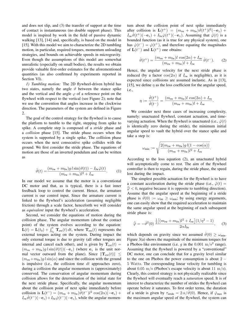
which depends on gravity since we assumed ϑ(0) ≥ ωmin.Figure 3(a) shows the magnitude of the minimum torques fora Phobos-like environment (i.e. g in the 0.001 m/s2 range).Assuming that the flywheel is powered by a “conventional”DC motor, one can conclude that for a gravity level similarto the one on Phobos the power consumption is about 2 −5 Watts. The corresponding linear velocity for tumbling isabout 0.05 m/s (Phobos’s escape velocity is about 11 m/s).Clearly, this control strategy is not physically realizable sincethe flywheel will eventually reach a saturation speed. It is ofinterest to characterize the number of strides the flywheel canoperate before it saturates. To first order terms, the durationof a stride is given by τstride = 2α/ϑ(0). Hence, if ϕmax isthe maximum angular speed of the flywheel, the system can
0.4 0.5 0.610
−2
10−1
Length of spikes (m)
To
rqu
e (
Nm
)
0 0.05 0.110
−2
10−1
100
101
Gravity (m/s2)
To
rqu
e (
Nm
)
(a) Torques for tumbling motion. Left figure: torque vs. spikes’ length(gravity g = 0.001 m/s2). Right figure: torque vs. gravity (spikes’length l = 0.4 m).
0.4 0.5 0.610
−2
10−1
100
Length of spikes (m)
To
rqu
e (
Nm
)
0 0.05 0.110
−2
10−1
100
101
Gravity (m/s2)
To
rqu
e (
Nm
)
(b) Torques for hopping motion. Left figure: torque vs. spikes’ length(gravity g = 0.001 m/s2). Right figure: torque vs. gravity (spikes’length l = 0.4 m).
Fig. 3. Minimum torques for tumbling and hopping motion (the y-axis isin logarithmic scale). System’s parameters: platform’s mass equal to 2.9 kg,flywheel’s mass equal to 0.1 kg (hence the total mass is 3 kg), radius ofplatform equal to 0.2 m, and 4 spikes (hence α = π/4). Longer spikesfacilitate tumbling over large rocks but require higher torques.
operate for a number of cycles (i.e., strides) equal to:
Nmax =2 ϕmax Ifw
ϑ(0)[(mrw +mfw)l2 + Irw](1/η2 − 1).
For a Phobos-like environment (i.e. g in the 0.001 m/s2
range), assuming that the maximum rpm for the flywheelmotor is 10,000, the maximum number of cycles is thenequal to ' 160 (or about 150 m). A few comments arein order. First, one can see that with realistic values for thesystem parameters (e.g., the gravity acceleration is similar tothat of Phobos) the platform can tumble at an average speedof 3 cm/s for about 150 m drawing a current of about 0.002A. Second, the formula for the constant acceleration control(equation (3)) shows that such value depends quadratically onthe length of the spikes, hence there is an important tradeoffbetween the capability of negotiating obstacles (that wouldrequire long spikes) and the amount of actuation (that prefersshort spikes). Third, the actuation level depends quadraticallyon the desired angular speed. Fourth, as already mentioned,the above control strategy has the disadvantage that aftersome time the flywheel will reach the saturation limit for itsspeed. This issue will be addressed in more detail at thenend of this section.
Finally, by allowing a time-varying actuation for theflywheel, one can guarantee, perhaps surprisingly, that theangular speed of both the platform and the flywheel are thesame at the beginning of each stride (i.e., there is forwardmotion but no net increase in flywheel’s speed). Following[15], this can be achieved through a 4-step control strategy:1) while ϑ is negative the flywheel is negatively accelerated
(ϕ < 0); 2) when ϑ becomes positive the flywheel ispositively accelerated (i.e., ϕ > 0) in such a way that therotation of the system is stopped (i.e., ϑ = 0) and for acertain interval of time (depending on η) angular momentumis accumulated; 3) the flywheel is negatively accelerated toquickly reduce its speed to the initial speed; 4) the flywheelis then left unactuated until collision (i.e., until ϑ = α).
It is of interest to characterize the fundamental limitationsof performance for control policies that avoid a build-upin flywheel’s velocity. By rather simple angular momentumarguments (see [15, page 24] for the details of a very similarderivation), one can show that a hybrid undergoing a steady-state (i.e., with equal angular velocity at each start of stride)tumbling motion with zero initial and final flywheel speedsand with non-negative net flywheel rotation can travel at aground speed no larger than:
vmax :=2l sin(α) (mrw +mfw) g l sin(α)√2α (1− η)[(mrw +mfw)l2 + Irw]
.
For a Phobos-like environment and hybrid’s parameters asin Figure 3, vmax ≈ 5 cm/s.
2) Hopping: A very similar analysis can be performedfor the hopping motion. Specifically, we study the followingmodel: a hybrid starts by rotating around a spike accordingto the tumbling motion described in the previous section.When the next spike impacts the ground, we still assume thatthe collision is impulsive and inelastic and that the transferof support is instantaneous; however, we do not constrainthe new stance foot to act as a pin joint, and we study theminimum angular speed that makes the hybrid “hop” or,more precisely, makes the stance foot complete a rotationof 2α without contacting the ground. One can show thathopping is achieved with a constant flywheel deceleration(assuming no saturation) equal to:
ϕ ≤ − g
Ifwmin
(mrw+mfw)l sin(α),
(mrw+mfw)l2+Irw
4 η2 l cos(α)α
.
Figure 3(b) shows the magnitude of the minimum torquesfor a Phobos-like environment.
3) Desaturation strategies for the flywheel: A key feasi-bility aspect for such mobility concept is flywheel’s speedsaturation. The simple 2D model suggests several strategiesto mitigate this problem. The first and second strategieswere previously discussed: operate without consideration ofsaturation; and careful acceleration and deceleration of theflywheel such that forward motion is produced without a netincrease in flywheel speed. The first strategy is reasonablefor very low gravity and/or moderate coverage requirements(≈ 100 m for Phobos-like conditions). The second is mosteffective, but requires sophisticated sensing and control.Third strategy: after a certain number of tumbles/hops, theflywheel is slowly despun in such a way that the platformdoes not tip over. This strategy is simple but substantiallydecreases the hybrid’s average speed. Fourth strategy (insome sense dual of the third strategy): the flywheel is slowlyaccelerated (such that the platform does not tip over) and thendecelerated in a very short time interval (by using brakes).

In this way the hybrid starts a hop/tumble with a flywheelangular velocity of zero. This strategy is further developedin Section IV.
B. 3D Numerical model
Prior work on microgravity mobility has either simulateddynamics of rigid bodies without motion planning [9], [16],or studied planning algorithms for mobility platforms mod-eled as point masses [17]. In this section we present a3D model for the hybrids that will be used in Section IVto develop planning algorithms on a realistic, rigid bodyrepresentation of the hybrid. This model allows for theelimination of some of the assumptions required for theanalytical model (e.g., single contact point acting as a pivot).By extending the work in [18], the Newtonian equations forthe equations of motion for the hybrid (including the internalflywheels) are as follows (the notation is defined in Table I):
• Position and velocity:brcm = bvcm,
bvcm =F
mtot− 2
(IΩbd × bvcm
)−
(Iαbd × brcm
)−
IΩbd ×(
IΩbd × bvcm
).
• Euler parameters:bε1bε2bε3bε4
=1
2
bε4 − bε3
bε2bε1
bε3bε4 − bε1
bε2− bε2
bε1bε4
bε3− bε1 − bε2 − bε3
bε4
bω1bω2bω30
.• Angular velocities:I1 0 0 JBβB1 JCβC1 JDβD1
0 I2 0 JBβB2 JCβC2 JDβD2
0 0 I3 JBβB3 JCβC3 JDβD3
βB1 βB2 βB3 1 0 0βC1 βC2 βC3 0 1 0βD1 βD2 βD3 0 0 1
Iω1Iω2Iω3sωBsωCsωD
=
M1 + (I2 − I3) Iω2Iω3 +
∑k = B,C,D
(Jk
sωk(βk2
Iω3 − βk3Iω2
))M2 + (I3 − I1) Iω3
Iω1 +∑
k = B,C,D
(Jk
sωk(βk3
Iω1 − βk1Iω3
))M3 + (I1 − I2) Iω1
Iω2 +∑
k = B,C,D
(Jk
sωk(βk1
Iω2 − βk2Iω1
))sMB · ~βB
JBsMC · ~βC
JCsMD · ~βD
JD
.
The external loads, F, and external moments, M, are cal-culated according to a simple spring-damper-friction contactmodel. The force normal to the ground is modeled as aspring-damper system and transverse forces are calculatedusing a Coulomb friction model. While these models arereasonably accurate for hard surfaces, soft, granular media(as it is the case for regoliths) requires a more sophisticatedcontact model, which is left for future work.
In the above dynamics equations, except for the termssMk · ~βk, all of the variables are either state variables, orcontact forces that are found by solving the set of differentialequations, or terms that are known a priori. Each sMk · ~βkterm represents the torque applied along the central axis of
Definitionbrcm position of spacecraft cm w.r.t. celestial bodybvcm velocity of spacecraft cm w.r.t. celestial bodyF net external force on spacecraftmtot total mass of spacecraft w/ flywheelsIΩbd angular velocity of celestial body w.r.t. inertialIαbd angular acceleration of celestial body w.r.t. inertialbεi ith Euler orientation parameter w.r.t. celestial bodybωi ith angular velocity of craft w.r.t. celestial bodyIωi ith angular velocity of craft w.r.t. inertialIi ith principle MOI of craft about cmJk axial MOI of flywheel k (k = B, C, D )~βk axis of rotation of flywheel k w.r.t. spacecraftsωk angular velocity of flywheel k w.r.t. spacecraftsMk torque on flywheel k from spacecraftMk ith component of net external torque on spacecraft
TABLE INOTATION FOR THE DYNAMICS EQUATIONS.
the kth flywheel and acts as one of the control inputs tothe system. A predetermined profile of the control variablesmust be fed into the system (open-loop control), or closed-loop control must be used to generate these values during thesimulation. Section IV details a closed-loop, hybrid approachfor the flywheels to achieve waypoint tracking.
IV. PLANNING AND CONTROL
The current computational model is restricted to uniformgravity fields and perfectly spherical terrain. Even underthese idealized conditions, motion planning and control isstill a significant challenge. The main difficulties stem fromthe gyroscopic coupling of the rotational degrees of freedomdue to flywheel motion, and the unpredictable nature ofhopping/bouncing due to the hybrid’s non-spherical shape.
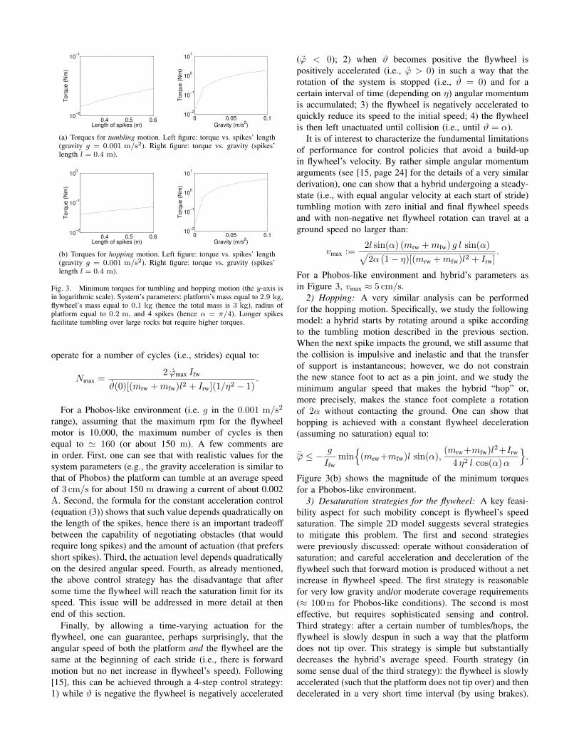
Our approach consists of a simple 3-mode hybrid controlalgorithm, whereby the flywheels are slowly accelerated toa desired angular velocity (referred to as “objective netangular velocity”), and then impulsively braked to generatethe torque needed to produce hopping/tumbling. Figure 4diagrams the control modes and the switching conditions.
Specifically, the key idea behind the proposed motionplanning algorithm is that the net angular velocities of theflywheels prior to braking should form a vector that ismutually orthogonal to both the heading and local gravityvectors. In this way, the torque from braking the flywheelscauses the hybrid to tumble or hop in the general directionof the next waypoint. Deviations from the intended hoppingdirection, caused by a non-spherical geometry (e.g. edges,spikes), are compensated for by applying this approach to asequence of hops/tumbles. Accordingly, the direction of theobjective net flywheel angular velocity prior to braking is
ωobjective =~h× ~g∣∣∣~h× ~g∣∣∣ , (4)
where ωobjective is the unit vector of the objective net angularvelocity of flywheels, ~g is the local gravity vector, and ~his the heading vector to the next waypoint (see Figure 5).
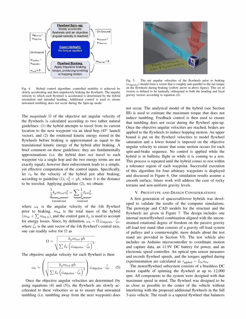
Fig. 4. Hybrid control algorithm: controlled mobility is achieved byslowly accelerating and then impulsively braking the flywheels. The angularvelocity to which each flywheel is accelerated is determined by the hybridorientation and intended heading. Additional control is used to ensureunwanted tumbling does not occur during the Spin-up mode.
The magnitude Ω of the objective net angular velocity ofthe flywheels is calculated according to two rather naturalguidelines: (1) the hybrid attempts to travel from its currentlocation to the next waypoint via an ideal hop (45 launchvector), and (2) the rotational kinetic energy stored in theflywheels before braking is approximated as equal to thetranslational kinetic energy of the hybrid after braking. Abrief comment on these guidelines: they are fundamentallyapproximations (i.e. the hybrid does not travel to eachwaypoint via a single hop and the two energy terms are notexactly equal), however their enforcement leads to a simple,yet effective computation of the control inputs. Specifically,let v0 be the velocity of the hybrid just after braking;according to guideline (1), v20 = gh, where h is the distanceto be traveled. Applying guideline (2), we obtain:
1
2kpmtotv
20︸ ︷︷ ︸
translational
=∑ 1
2Ikω
2k︸ ︷︷ ︸
rotational
,
where ωk is the angular velocity of the kth flywheelprior to braking, mtot is the total mass of the hybrid(mrw +
∑mfw,k), and the control gain kp is used to account
for energy losses. Since, by definition, ωk = Ω ωobjective · ~ζk,where ~ζk is the unit vector of the kth flywheel’s central axis,one can readily solve for Ω as
Ω =
√√√√ kpmtot gh∑Ik
(ωobjective · ~ζk
)2 .The objective angular velocity for each flywheel is then:
ωk =
√√√√ kpmtot gh∑Ik
(ωobjective · ~ζk
)2 ωobjective · ~ζk. (5)
Once the objective angular velocities are determined (byusing equations (4) and (5)), the flywheels are slowly ac-celerated to these velocities so as to ensure that unwantedtumbling (i.e. tumbling away from the next waypoint) does
Fig. 5. The net angular velocities of the flywheels prior to braking(ωobjective) should form a vector that is roughly anti-parallel to the net torqueon the flywheels during braking (yellow arrow in above figure). This set ofvectors is defined to be mutually orthogonal to both the heading and localgravity vectors according to equation (4).
not occur. The analytical model of the hybrid (see SectionIII) is used to estimate the maximum torque that does notinduce tumbling. Feedback control is then used to ensurethat tumbling does not occur during the flywheel spin-up.Once the objective angular velocities are reached, brakes areapplied to the flywheels to induce hopping motion. An upperbound is put on the flywheel velocities to model flywheelsaturation and a lower bound is imposed on the objectiveangular velocity to ensure that some motion occurs for eachspin-and-brake sequence. No control is applied while thehybrid is in ballistic flight or while it is coming to a rest.This process is repeated until the hybrid comes to rest withina tolerance region of each waypoint. Successful executionof this algorithm for four arbitrary waypoints is displayedand discussed in Figure 6. Our simulation results assume asmooth surface; future work will address the case of rockyterrains and non-uniform gravity levels.
V. PROTOTYPE AND DESIGN CONSIDERATIONS
A first generation of spacecraft/rover hybrids was devel-oped to validate the results of the computer simulations.The prototype and CAD models for the structure and theflywheels are given in Figure 7. The design includes oneinternal motor/flywheel combination aligned with the uncon-strained rotational degree of freedom on the passive gravityoff-load test stand (that consists of a gravity off-load systemof pulleys and a counterweight; more details about the teststand are provided in Section VI). The test vehicle alsoincludes an Arduino microcontroller to coordinate motionand capture data, an 11.9V DC battery for power, and anelectronic speed controller. An optical rpm sensor measuresand records flywheel speeds, and the torques applied duringexperimentation are calculated as τapplied = Ifwαfw.
The motor/flywheel subsystem consists of a brushless DCmotor capable of spinning the flywheel at up to 12,000rpm. All components in the system were designed with thatmaximum speed in mind. The flywheel was designed to beas close as possible to the center of the vehicle withoutinterfering with the proposed additional flywheels in the full3-axis vehicle. The result is a tapered flywheel that balances
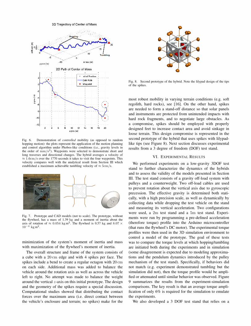
Fig. 6. Demonstration of controlled mobility (as opposed to randomhopping motion): the plots represent the application of the motion planningand control algorithm under Phobos-like conditions (i.e., gravity levels inthe order of mm/s2). Waypoints were selected to demonstrate short andlong traverses and directional changes. The hybrid averages a velocity of≈ 1.6cm/s over the 1770 seconds it takes to visit the four waypoints. Thisvelocity compares well with the analytical result from Section III whichestablished a maximum achievable tumbling velocity of ≈ 5cm/s.
Fig. 7. Prototype and CAD models (not to scale). The prototype, withoutthe flywheel, has a mass of 1.39 kg and a moment of inertia about theaxis of rotation of ≈ 0.054 kg m2. The flywheel is 0.57 kg and 8.07 ×10⁻⁴ kg m2.
minimization of the system’s moment of inertia and masswith maximization of the flywheel’s moment of inertia.
The overall structure and frame of the system consists ofa cube with a 20 cm edge and with 4 spikes per face. Thespikes include a bend to create a regular octagon with 20 cmon each side. Additional mass was added to balance thevehicle around the rotation axis as well as across the vehicleleft to right. No attempt was made to balance the weightaround the vertical z-axis on this initial prototype. The designand the geometry of the spikes require a special discussion.Computational studies showed that distributing the contactforces over the maximum area (i.e. direct contact betweenthe vehicle’s enclosure and terrain; no spikes) make for the
Fig. 8. Second prototype of the hybrid. Note the lilypad design of the tipsof the spikes.
most robust mobility in varying terrain conditions (e.g. softregolith, hard rocks), see [16]. On the other hand, spikesare needed to form a stand-off distance so that solar panelsand instruments are protected from unintended impacts withhard rock fragments, and to negotiate large obstacles. Asa compromise, spikes should be employed with properlydesigned feet to increase contact area and avoid sinkage inloose terrain. This design compromise is represented in thesecond prototype of the hybrid that uses spikes with lilypad-like tips (see Figure 8). Next section discusses experimentalresults from a 3 degree of freedom (DOF) test stand.
VI. EXPERIMENTAL RESULTS
We performed experiments on a low-gravity 3DOF teststand to further characterize the dynamics of the hybridsand to assess the validity of the models presented in SectionIII. The test stand consists of a gravity off-load system withpulleys and a counterweight. Two off-load cables are usedto prevent rotation about the vertical axis due to gyroscopicprecession. The effective gravity is determined both stati-cally, with a high precision scale, as well as dynamically bycollecting data while dropping the test vehicle on the standand measuring its vertical acceleration. Two configurationswere used, a 2m test stand and a 5m test stand. Experi-ments were run by programming a pre-defined acceleration(therefore torque) profile into the Arduino microcontroller(that runs the flywheel’s DC motor). The experimental torqueprofiles were then used in the 3D simulation environment tocontrol a model of the prototype. The goal of these testswas to compare the torque levels at which hopping/tumblingare initiated both during the experiments and in simulation(some disagreement is expected due to modeling approxima-tions and the pendulum dynamics introduced by the pulleymechanism of the test stand). Specifically, if behaviors didnot match (e.g. experiment demonstrated tumbling but thesimulation did not), then the torque profile would be ampli-fied or attenuated until similar behavior was observed. Figure9 summarizes the results from the experiment-simulationcomparisons. The key result is that an average torque ampli-fication of only 6% is required for the simulation to emulatethe experiments.
We also developed a 3 DOF test stand that relies on a

Fig. 9. Experiment-Simulation comparison: values indicate the amount bywhich the torque profile had to be modified in simulation to match motionobserved in experiments. The effective gravity for this set of experimentswas 0.235 m/s2 .
β
Free-floatingrobot
Tilted table
Emulated gravity ∝ β
Fig. 10. 3 DOF test stand on a frictionless table; by tilting the granitetable, one can create a “small” force that emulates a low gravity field.
frictionless table and does not require any pulley system (and,hence, does not introduce any exogenous dynamics). The teststand consists of a metallic plate that is air-bearing supportedover a table and a flywheel attached at the top. The table isslightly tilted in order to emulate a low-gravity environmentin 2D (with an emulated gravity of about 0.05 m/s2), seeFigure 10. Baking flour is used as a simulant for regolithfound in microgravity environments. We recorded tumblingspeeds of ≈ 2 cm/s and hops up to distances of ≈ 0.5 m(longer hops were theoretically possible, but could not beimplemented due to the size of the granite table). In general,experimental results on this test stand are in agreement withthe results from the pulley system test stand, the analyticalmodel results, and the numerical simulation results; suchresults, however, are not discussed here due to space lim-itations.
VII. CONCLUSIONS
In this paper we presented a planetary mobility platformthat relies on internal actuation and can perform both longexcursions (by hopping) and short, precise traverses (throughcontrolled “tumbles”) in low-gravity environments. We havediscussed dynamical properties of the platform, planningand control algorithms, the design of a first prototype, andinitial experimental results. Collectively, our results lay thefoundations for the design of internally-actuated rovers withcontrolled mobility (as opposed to random hopping motion).This paper leaves numerous important extensions open forfurther research. First, we seek to refine our planning and
control algorithms to reliably maneuver on rocky terrainsand to minimize a given cost criterion (e.g., time or energyexpenditure). Second, it is important to develop appropriatecontact models for the interaction with loose, granular mediatypically encountered on small bodies. Third, while wealready have first-order estimates (not discussed here due tospace limitations) for critical subsystems (e.g., power, ther-mal, and communication), we plan to refine subsystem designand select an appropriate scientific payload for potentialexploration targets (e.g., Phobos). Finally, we plan to developan actively controlled, 5 DOF test stand that allows for morethorough investigation of motion planning techniques andcontinued validation of computational models.
REFERENCES
[1] Decadal Survey Vision and Voyages for PlanetaryScience in the Decade 2013–2022. Technical re-port, National Research Council, 2011. Available athttp://solarsystem.nasa.gov/2013decadal/.
[2] J. C. Castillo-Rogez, M. Pavone, I.A.D. Nesnas, and J.A. Hoffman.Expected science return of spatially-extended in-situ exploration atsmall Solar System bodies. In Aerospace Conference, 2012 IEEE,pages 1 –15, March 2012.
[3] M. Wargo. Strategic knowledge gaps. 2012. Available athttp://science.nasa.gov/media/medialibrary/2012/05/04/HEOMD_Strategic_Knowledge_Gaps_--_Mike_Wargo.pdf.
[4] P.M. Cunio, F. Alibay, P. Meira, T. Sheerin, E. Lanford, E. Krupczak,and J.A. Hoffman. Options in the solar system for planetary surfaceexploration via hopping. In Aerospace Conference, 2011 IEEE, pages1 –10, march 2011.
[5] R.M. Jones. The MUSES–CN rover and asteroid exploration mission.In 22nd International Symposium on Space Technology and Science,pages 2403–2410, 2000.
[6] M. Chacin, A. Mora, and K. Yoshida. Motion control of multi-limbedrobots for asteroid exploration missions. In Proc. IEEE Conf. onRobotics and Automation, pages 3037–3042, May 2009.
[7] A. Seeni, B. Schafer, B. Rebele, and N. Tolyarenko. Robot mobilityconcepts for extraterrestrial surface exploration. In Aerospace Confer-ence, 2008 IEEE, pages 1–14, March 2008.
[8] P. Fiorini and J. Burdick. The development of hopping capabilitiesfor small robots. Autonomous Robots, 14:239–254, 2003.
[9] C. Dietze, S. Herrmann, F. Kuß, C. Lange, M. Scharringhausen,L. Witte, T. van Zoest, and H Yano. Landing and mobility conceptfor the small asteroid lander MASCOT on asteroid 1999 JU3. In 61stInternational Astronautical Congress, 2010.
[10] R.Z. Sagdeev and A.V Zakharov. Brief history of the Phobos mission.Nature, 341:581–585, 1989.
[11] JAXA Hayabusa mission. Technical report, JAXA, 2011. Available athttp://hayabusa.jaxa.jp/e/index.html.
[12] D. Scheeres. Close proximity operations for implementing mitigationstrategies. In Planetary Defense Conference: Protecting Earth fromAsteroids, Orange County, CA, February 2004.
[13] T. McGeer. Passive dynamic walking. The International Journal ofRobotics Research, 9(2):62–82, 1990.
[14] K. Byl and R. Tedrake. Metastable walking machines. The Interna-tional Journal of Robotics Research, 28(8):1040–1064, 2009.
[15] G.W. Howell. Analysis and control of super-articulated biped robots.Dissertation, Boston University, 2000.
[16] F. Herrmann, S. Kuß, and B. Schafer. Mobility challenges and possiblesolutions for low-gravity planetary body exploration. In ESA/ESTEC,Noordwijk, Netherlands, April 2011.
[17] Bellerose. J. and D. Scheeres. Dynamics and Control for SurfaceExploration of Small Bodies. In AIAA/AAS Astrodynamics SpecialistConference and Exhibit, number 6251, Honolulu, HI, August 2008.
[18] T. Kane, P. Likins, and D. Levinson. Spacecraft Dynamics, pages218–223. The Internet-First University Press, 2005.