international iec standard 62220-1ners580/ners-bioe_481/lectures/pdfs/2003-10-iec... ·...
TRANSCRIPT

INTERNATIONALSTANDARD
IEC62220-1
First edition2003-10
Medical electrical equipment –Characteristics of digital X-ray imaging devices –Part 1: Determination of the detective quantumefficiency
Appareils électromédicaux –Caractéristiques des appareils d'imagerie à rayonnement X –Partie 1: Détermination de l'efficacité quantique de détection
Reference numberIEC 62220-1:2003(E)
Licensed to Henry Ford Health System/Michael FlynnANSI Store order #X214510 Downloaded: 10/21/2005 9:53:12 AM ETSingle user license only. Copying and networking prohibited.

Publication numbering
As from 1 January 1997 all IEC publications are issued with a designation in the 60000 series. For example, IEC 34-1 is now referred to as IEC 60034-1.
Consolidated editions
The IEC is now publishing consolidated versions of its publications. For example, edition numbers 1.0, 1.1 and 1.2 refer, respectively, to the base publication, the base publication incorporating amendment 1 and the base publication incorporating amendments 1 and 2.
Further information on IEC publications
The technical content of IEC publications is kept under constant review by the IEC, thus ensuring that the content reflects current technology. Information relating to this publication, including its validity, is available in the IEC Catalogue of publications (see below) in addition to new editions, amendments and corrigenda. Information on the subjects under consideration and work in progress undertaken by the technical committee which has prepared this publication, as well as the list of publications issued, is also available from the following:
• IEC Web Site (www.iec.ch)
• Catalogue of IEC publications
The on-line catalogue on the IEC web site (www.iec.ch/searchpub) enables you to search by a variety of criteria including text searches, technical committees and date of publication. On-line information is also available on recently issued publications, withdrawn and replaced publications, as well as corrigenda.
• IEC Just Published
This summary of recently issued publications (www.iec.ch/online_news/ justpub) is also available by email. Please contact the Customer Service Centre (see below) for further information.
• Customer Service Centre
If you have any questions regarding this publication or need further assistance, please contact the Customer Service Centre:
Email: [email protected] Tel: +41 22 919 02 11 Fax: +41 22 919 03 00
Licensed to Henry Ford Health System/Michael FlynnANSI Store order #X214510 Downloaded: 10/21/2005 9:53:12 AM ETSingle user license only. Copying and networking prohibited.
INTERNATIONALSTANDARD
IEC62220-1
First edition2003-10
Medical electrical equipment –Characteristics of digital X-ray imaging devices –Part 1: Determination of the detective quantumefficiency
Appareils électromédicaux –Caractéristiques des appareils d'imagerie à rayonnement X –Partie 1: Détermination de l'efficacité quantique de détection
IEC 2003 Copyright - all rights reserved
No part of this publication may be reproduced or utilized in any form or by any means, electronic ormechanical, including photocopying and microfilm, without permission in writing from the publisher.
International Electrotechnical Commission, 3, rue de Varembé, PO Box 131, CH-1211 Geneva 20, SwitzerlandTelephone: +41 22 919 02 11 Telefax: +41 22 919 03 00 E-mail: [email protected] Web: www.iec.ch
UFor price, see current catalogue
PRICE CODECommission Electrotechnique InternationaleInternational Electrotechnical CommissionМеждународная Электротехническая Комиссия
Licensed to Henry Ford Health System/Michael FlynnANSI Store order #X214510 Downloaded: 10/21/2005 9:53:12 AM ETSingle user license only. Copying and networking prohibited.

– 2 – 62220-1 IEC:2003(E)
CONTENTS
FOREWORD .......................................................................................................................... 3INTRODUCTION .................................................................................................................... 51 Scope .............................................................................................................................. 62 Normative references....................................................................................................... 63 Terminology and definitions ............................................................................................. 74 Requirements .................................................................................................................. 8
4.1 Operating conditions............................................................................................... 84.2 X-RAY EQUIPMENT .................................................................................................... 84.3 RADIATION QUALITY .................................................................................................. 94.4 TEST DEVICE ...........................................................................................................104.5 Geometry...............................................................................................................114.6 IRRADIATION conditions ...........................................................................................13
4.6.1 General conditions .....................................................................................134.6.2 Exposure measurement .............................................................................134.6.3 Avoidance of LAG EFFECTS ..........................................................................144.6.4 IRRADIATION to obtain the CONVERSION FUNCTION.........................................144.6.5 IRRADIATION for determination of the NOISE POWER SPECTRUM ......................144.6.6 IRRADIATION with TEST DEVICE in the RADIATION BEAM ...................................15
5 Corrections of RAW DATA .................................................................................................166 Determination of the DETECTIVE QUANTUM EFFICIENCY.......................................................16
6.1 Definition and formula of DQE(u,v) .........................................................................166.2 Parameters to be used for evaluation ....................................................................176.3 Determination of different parameters from the images ..........................................17
6.3.1 Linearization of data ..................................................................................176.3.2 The NOISE POWER SPECTRUM (NPS) .............................................................186.3.3 Determination of the MODULATION TRANSFER FUNCTION (MTF) ......................20
7 Format of conformance statement...................................................................................208 Accuracy.........................................................................................................................21
Annex A (normative) Determination of LAG EFFECTS ..............................................................23A.1 Test of additive LAG EFFECTS ..................................................................................23A.2 Test of multiplicative LAG EFFECTS ..........................................................................24
Annex B (normative) Terminology – Index of defined terms ..................................................26Annex C (informative) Calculation of the input NOISE POWER SPECTRUM.................................27
Bibliography ..........................................................................................................................28
Licensed to Henry Ford Health System/Michael FlynnANSI Store order #X214510 Downloaded: 10/21/2005 9:53:12 AM ETSingle user license only. Copying and networking prohibited.

62220-1 IEC:2003(E) – 3 –
INTERNATIONAL ELECTROTECHNICAL COMMISSION____________
MEDICAL ELECTRICAL EQUIPMENT –CHARACTERISTICS OF DIGITAL X-RAY IMAGING DEVICES –
Part 1: Determination of the detective quantum efficiency
FOREWORD1) The International Electrotechnical Commission (IEC) is a worldwide organization for standardization comprising
all national electrotechnical committees (IEC National Committees). The object of IEC is to promoteinternational co-operation on all questions concerning standardization in the electrical and electronic fields. Tothis end and in addition to other activities, IEC publishes International Standards, Technical Specifications,Technical Reports, Publicly Available Specifications (PAS) and Guides (hereafter referred to as “IECPublication(s)”). Their preparation is entrusted to technical committees; any IEC National Committee interestedin the subject dealt with may participate in this preparatory work. International, governmental and non-governmental organizations liaising with the IEC also participate in this preparation. IEC collaborates closelywith the International Organization for Standardization (ISO) in accordance with conditions determined byagreement between the two organizations.
2) The formal decisions or agreements of IEC on technical matters express, as nearly as possible, an internationalconsensus of opinion on the relevant subjects since each technical committee has representation from allinterested IEC National Committees.
3) IEC Publications have the form of recommendations for international use and are accepted by IEC NationalCommittees in that sense. While all reasonable efforts are made to ensure that the technical content of IECPublications is accurate, IEC cannot be held responsible for the way in which they are used or for anymisinterpretation by any end user.
4) In order to promote international uniformity, IEC National Committees undertake to apply IEC Publicationstransparently to the maximum extent possible in their national and regional publications. Any divergencebetween any IEC Publication and the corresponding national or regional publication shall be clearly indicated inthe latter.
5) IEC provides no marking procedure to indicate its approval and cannot be rendered responsible for anyequipment declared to be in conformity with an IEC Publication.
6) All users should ensure that they have the latest edition of this publication.
7) No liability shall attach to IEC or its directors, employees, servants or agents including individual experts andmembers of its technical committees and IEC National Committees for any personal injury, property damage orother damage of any nature whatsoever, whether direct or indirect, or for costs (including legal fees) andexpenses arising out of the publication, use of, or reliance upon, this IEC Publication or any other IECPublications.
8) Attention is drawn to the Normative references cited in this publication. Use of the referenced publications isindispensable for the correct application of this publication.
9) Attention is drawn to the possibility that some of the elements of this IEC Publication may be the subject ofpatent rights. IEC shall not be held responsible for identifying any or all such patent rights.
International Standard IEC 62220-1 has been prepared by subcommittee 62B: Diagnosticimaging equipment, of IEC technical committee 62: Electrical equipment in medical practice.
The text of this standard is based on the following documents:
FDIS Report on voting
62B/493/FDIS 62B/506/RVD
Full information on the voting for the approval of this standard can be found in the report onvoting indicated in the above table.
This publication has been drafted in accordance with the ISO/IEC Directives, Part 2.
Licensed to Henry Ford Health System/Michael FlynnANSI Store order #X214510 Downloaded: 10/21/2005 9:53:12 AM ETSingle user license only. Copying and networking prohibited.

– 4 – 62220-1 IEC:2003(E)
In this standard, terms printed in SMALL CAPITALS are used as defined in IEC 60788, inClause 3 of this standard or other IEC publications referenced in Annex B. Where a definedterm is used as a qualifier in another defined or undefined term it is not printed in SMALLCAPITALS, unless the concept thus qualified is defined or recognized as a “derived termwithout definition”.
NOTE Attention is drawn to the fact that, in cases where the concept addressed is not strongly confined to thedefinition given in one of the publications listed above, a corresponding term is printed in lower-case letters.
The committee has decided that the contents of this publication will remain unchanged until2006-12. At this date, the publication will be
• reconfirmed;• withdrawn;• replaced by a revised edition, or• amended.
Licensed to Henry Ford Health System/Michael FlynnANSI Store order #X214510 Downloaded: 10/21/2005 9:53:12 AM ETSingle user license only. Copying and networking prohibited.

62220-1 IEC:2003(E) – 5 –
INTRODUCTION
DIGITAL X-RAY IMAGING DEVICES are increasingly used in medical diagnosis and will widelyreplace conventional (analogue) imaging devices such as screen-film systems or analogue X-RAY IMAGE INTENSIFIER television systems in the future. It is necessary, therefore, to defineparameters that describe the specific imaging properties of these DIGITAL X-RAY IMAGINGDEVICES and to standardize the measurement procedures employed.
There is growing consensus in the scientific world that the DETECTIVE QUANTUM EFFICIENCY(DQE) is the most suitable parameter for describing the imaging performance of an X-rayimaging device. The DQE describes the ability of the imaging device to preserve the signal-to-NOISE ratio from the radiation field to the resulting digital image data. Since in X-ray imaging,the NOISE in the radiation field is intimately coupled to the exposure level, DQE values canalso be considered to describe the dose efficiency of a given imaging device.
NOTE 1 In spite of the fact that the DQE is widely used to describe the performance of imaging devices, theconnection between this physical parameter and the decision performance of a human observer is not yetcompletely understood [1], [3] .1)
NOTE 2 The standard IEC 61262-5 specifies a method to determine the DQE of X-RAY IMAGE INTENSIFIERS atnearly zero SPATIAL FREQUENCY. It focuses only on the electro-optical components of X-RAY IMAGE INTENSIFIERS, noton the imaging properties as this standard does. As a consequence, the output is measured as an optical quantity(luminance), and not as digital data. Moreover, IEC 61262-5 prescribes the use of a RADIATION SOURCE ASSEMBLY,whereas this standard prescribes the use of an X-RAY TUBE. The scope of IEC 61262-5 is limited to X-RAY IMAGEINTENSIFIERS and does not interfere with the scope of this standard.
The DQE is already widely used by manufacturers to describe the performance of theirequipment. The specification of the DQE is also required by regulatory agencies (such as theFood and Drug Administration (FDA)) for admission procedures. However, there is presentlyno standard governing either the measurement conditions or the measurement procedure withthe consequence that values from different sources may not be comparable.
This standard has therefore been developed in order to specify the measurement proceduretogether with the format of the conformance statement for the DETECTIVE QUANTUM EFFICIENCYof DIGITAL X-RAY IMAGING DEVICES.
In the DQE calculations proposed in this standard, it is assumed that system response ismeasured for objects that attenuate all energies equally (task-independent) [5].
The standard will be beneficial for manufacturers, users, distributors and regulatory agencies.It can be regarded as the first of a series describing all the relevant parameters of DIGITAL X-RAY IMAGING DEVICES.
———————1) Figures in square brackets refer to the bibliography.
Licensed to Henry Ford Health System/Michael FlynnANSI Store order #X214510 Downloaded: 10/21/2005 9:53:12 AM ETSingle user license only. Copying and networking prohibited.

– 6 – 62220-1 IEC:2003(E)
MEDICAL ELECTRICAL EQUIPMENT –CHARACTERISTICS OF DIGITAL X-RAY IMAGING DEVICES –
Part 1: Determination of the detective quantum efficiency
1 Scope
This part of IEC 62220 specifies the method for the determination of the DETECTIVE QUANTUMEFFICIENCY (DQE) of DIGITAL X-RAY IMAGING DEVICES as a function of exposure and of SPATIALFREQUENCY for the working conditions in the range of the medical application as specified bythe MANUFACTURER.
This part of IEC 62220 is applicable to projection DIGITAL X-RAY IMAGING DEVICES producingIMAGES in digital format that are used for medical diagnosis. It is restricted to DIGITAL X-RAYIMAGING DEVICES that are used for radiographic imaging, such as CR systems, selenium-basedsystems, flat panel detectors, optically coupled CCD detectors, and digital X-RAY IMAGEINTENSIFIERS used for single exposures.
This part of IEC 62220 is not applicable to
– DIGITAL X-RAY IMAGING DEVICES intended to be used in mammography or in dentalradiography;
– COMPUTED TOMOGRAPHY:– systems in which the X-ray field is scanned across the patient; and– devices for dynamic imaging (where series of images are acquired, as in fluoroscopic or
cardiac imaging).NOTE The devices noted above are excluded because they contain many parameters (for instance, beamqualities, geometry, time dependence, etc.) which differ from those important for general radiography. It is intendedto treat some of these techniques in separate standards as has been done for other topics, for instance for speedand contrast, in IEC and ISO standards.
2 Normative references
The following referenced documents are indispensable for the application of this document.For dated references, only the edition cited applies. For undated references, the latest editionof the referenced document (including any amendments) applies.
IEC 60336:1993, X-ray tube assemblies for medical diagnosis – Characteristics of focal spots
IEC 60601-2-7: Medical electrical equipment – Part 2-7: Particular requirements for the safetyof high-voltage generators of diagnostic X-ray generators
IEC 60788:1984, Medical radiology – Terminology
IEC 61267:1994, Medical diagnostic X-ray equipment – Radiation conditions for use in thedetermination of characteristics
ISO 12232:1998, Photography – Electronic still-picture cameras – Determination of ISO speed
Licensed to Henry Ford Health System/Michael FlynnANSI Store order #X214510 Downloaded: 10/21/2005 9:53:12 AM ETSingle user license only. Copying and networking prohibited.

62220-1 IEC:2003(E) – 7 –
3 Terminology and definitions
For the purposes of this part of IEC 62220 the following terms and definitions apply.
3.1 CENTRAL AXISline perpendicular to the ENTRANCE PLANE passing through the centre of the entrance field
3.2 CONVERSION FUNCTIONplot of the large area output level (ORIGINAL DATA) of a DIGITAL X-RAY IMAGING DEVICE versusthe number of exposure quanta per unit area (Q) in the DETECTOR SURFACE plane
NOTE 1 Q is to be calculated by multiplying the measured exposure excluding back scatter by the value given incolumn 2 of Table 2.
NOTE 2 Usually AIR KERMA is substituted for exposure.
NOTE 3 Many calibration laboratories, such as national metrology institutes, calibrate RADIATION METERS tomeasure AIR KERMA.
3.3 DETECTIVE QUANTUM EFFICIENCYDQE(u,v)ratio of two NOISE POWER SPECTRUM (NPS) functions with the numerator being the NPS of theinput signal at the DETECTOR SURFACE of a digital X-ray detector after having gone through thedeterministic filter given by the system transfer function, and the denominator being themeasured NPS of the output signal (ORIGINAL DATA)
NOTE Instead of the two-dimensional DETECTIVE QUANTUM EFFICIENCY, often a cut through the two-dimensional DETECTIVE QUANTUM EFFICIENCY along a specified SPATIAL FREQUENCY axis is published.
3.4 DETECTOR SURFACEarea which is closest to the IMAGE RECEPTOR PLANE with all protecting parts (including theANTI-SCATTER GRID and components for AUTOMATIC EXPOSURE CONTROL, if applicable) that canbe safely removed out of the RADIATION BEAM without damaging the digital X-ray detector
3.5 DIGITAL X-RAY IMAGING DEVICEdevice consisting of a digital X-ray detector including the protective layers installed for use inpractice, the amplifying and digitizing electronics, and a computer providing the ORIGINAL DATA(DN) of the image
3.6 IMAGE MATRIXarrangement of matrix elements in a preferably Cartesian coordinate system
3.7 LAG EFFECTinfluence from a previous image on the current one
3.8 LINEARIZED DATAORIGINAL DATA to which the inverse CONVERSION FUNCTION has been applied
NOTE The LINEARIZED DATA are directly proportional to the exposure.
Licensed to Henry Ford Health System/Michael FlynnANSI Store order #X214510 Downloaded: 10/21/2005 9:53:12 AM ETSingle user license only. Copying and networking prohibited.

– 8 – 62220-1 IEC:2003(E)
3.9 MODULATION TRANSFER FUNCTIONMTF(u,v)modulus of the generally complex optical transfer function, expressed as a function of SPATIALFREQUENCIES u and v3.10 NOISEfluctuations from the expected value of a stochastic process
3.11 NOISE POWER SPECTRUM(NPS)W(u,v)modulus of the Fourier transform of the NOISE auto-covariance function. The power of NOISE,contained in a two-dimensional SPATIAL FREQUENCY interval, as a function of the two-dimensional frequency
NOTE In literature, the NOISE POWER SPECTRUM is often named “Wiener spectrum” in honour of the mathematicianNorbert Wiener.
3.12 ORIGINAL DATADNRAW DATA to which the corrections allowed in this standard have been applied
3.13 PHOTON FLUENCEQmean number of photons per unit area
3.14 RAW DATApixel values read directly after the analogue-digital-conversion from the DIGITAL X-RAY IMAGINGDEVICE without any software corrections
3.15 SPATIAL FREQUENCYu or vinverse of the period of a repetitive spatial phenomenon. The dimension of the SPATIALFREQUENCY is inverse length
4 Requirements
4.1 Operating conditions
The DIGITAL X-RAY IMAGING DEVICE shall be stored and operated according to theMANUFACTURER’S recommendations. The warm-up time shall be chosen according to therecommendation of the MANUFACTURER. The operating conditions shall be the same as thoseintended for clinical use and shall be maintained during evaluation as required for the specifictests described herein.
Ambient climatic conditions in the room where the DIGITAL X-RAY IMAGING DEVICE is operatedshall be stated together with the results.
4.2 X-RAY EQUIPMENT
For all tests described in the following subclauses, a CONSTANT POTENTIAL HIGH-VOLTAGEGENERATOR shall be used (IEC 60601-2-7). The PERCENTAGE RIPPLE shall be equal to, or lessthan, 4.
Licensed to Henry Ford Health System/Michael FlynnANSI Store order #X214510 Downloaded: 10/21/2005 9:53:12 AM ETSingle user license only. Copying and networking prohibited.

62220-1 IEC:2003(E) – 9 –
The NOMINAL FOCAL SPOT VALUE (IEC 60336) shall be not larger than 1,2.
For the measurement of exposure, calibrated RADIATION METERS shall be used. Theuncertainty (coverage factor 2)[2] of the readings shall be less than 5 %.
NOTE 1 “Uncertainty” and “coverage factor” are terms defined in the ISO Guide to the expression of uncertainty inmeasurement [2] .
NOTE 2 RADIATION METERS to read AIR KERMA are, for instance, calibrated by many national metrology institutes.
4.3 RADIATION QUALITY
The RADIATION QUALITIES shall be one or more out of four selected RADIATION QUALITIESspecified in IEC 61267 (see Table 1). If only a single RADIATION QUALITY is used, RADIATIONQUALITY RQA5 should be preferred.
For the application of the RADIATION QUALITIES, refer to IEC 61267:1994.
NOTE 1 According to IEC 61267, RADIATION QUALITIES are defined by a fixed ADDITIONAL FILTRATION and aHALF-VALUE LAYER that is realized with this filtration by a suitable adaptation of the X-RAY TUBE VOLTAGE,starting from the approximate X-RAY TUBE VOLTAGE (Table 1).
Table 1 – RADIATION QUALITY (IEC 61267:1994) for the determinationof DETECTIVE QUANTUM EFFICIENCY and corresponding parameters
RADIATIONQUALITY No.
ApproximateX-RAY TUBE
VOLTAGEkV
HALF-VALUELAYER (HVL)
mm Al
ADDITIONALFILTRATION
mm Al
RQA 3 50 4,0 10,0
RQA 5 70 7,1 21,0
RQA 7 90 9,1 30,0
RQA 9 120 11,5 40,0
NOTE 2 The additional filtration is the filtration added to the inherent filtration of the X-RAY TUBE.
NOTE 3 The capability of X-RAY GENERATORS to produce low exposure levels may not be sufficient, especially forRQA9. In this case, it is recommended that the distance FOCAL SPOT to DETECTOR SURFACE be increased.
Licensed to Henry Ford Health System/Michael FlynnANSI Store order #X214510 Downloaded: 10/21/2005 9:53:12 AM ETSingle user license only. Copying and networking prohibited.
– 10 – 62220-1 IEC:2003(E)
4.4 TEST DEVICE
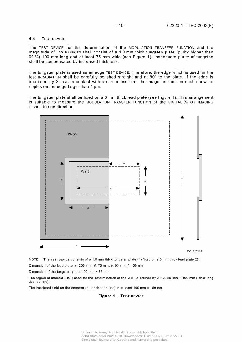
The TEST DEVICE for the determination of the MODULATION TRANSFER FUNCTION and themagnitude of LAG EFFECTS shall consist of a 1,0 mm thick tungsten plate (purity higher than90 %) 100 mm long and at least 75 mm wide (see Figure 1). Inadequate purity of tungstenshall be compensated by increased thickness.
The tungsten plate is used as an edge TEST DEVICE. Therefore, the edge which is used for thetest IRRADIATION shall be carefully polished straight and at 90° to the plate. If the edge isirradiated by X-rays in contact with a screenless film, the image on the film shall show noripples on the edge larger than 5 µm.
The tungsten plate shall be fixed on a 3 mm thick lead plate (see Figure 1). This arrangementis suitable to measure the MODULATION TRANSFER FUNCTION of the DIGITAL X-RAY IMAGINGDEVICE in one direction.
Pb (2)
W (1)
f
ab
c
b
e
d
IEC 2253/03
NOTE The TEST DEVICE consists of a 1,0 mm thick tungsten plate (1) fixed on a 3 mm thick lead plate (2).
Dimension of the lead plate: a: 200 mm, d: 70 mm, e: 90 mm, f: 100 mm.
Dimension of the tungsten plate: 100 mm × 75 mm.
The region of interest (ROI) used for the determination of the MTF is defined by b × c, 50 mm × 100 mm (inner longdashed line).
The irradiated field on the detector (outer dashed line) is at least 160 mm × 160 mm.
Figure 1 – TEST DEVICE
Licensed to Henry Ford Health System/Michael FlynnANSI Store order #X214510 Downloaded: 10/21/2005 9:53:12 AM ETSingle user license only. Copying and networking prohibited.

62220-1 IEC:2003(E) – 11 –
4.5 Geometry
The geometrical set-up of the measuring arrangement shall comply with Figure 2. The X-RAYEQUIPMENT is used in that geometric configuration in the same way as it is used for normaldiagnostic applications. The distance between the FOCAL SPOT of the X-RAY TUBE and theDETECTOR SURFACE should be not less than 1,50 m. If, for technical reasons, the distancecannot be 1,50 m or more, a smaller distance can be chosen but has to be explicitly declaredwhen reporting results.
The TEST DEVICE is placed immediately in front of the DETECTOR SURFACE. The centre of theedge of the TEST DEVICE should be aligned to the CENTRAL AXIS of the X-ray beam.Displacement from the CENTRAL AXIS will lower the measured MTF. The CENTRAL AXIS can belocated by maximizing the MTF as a function of TEST DEVICE displacement.
The recommended procedure is that the TEST DEVICE and the X-ray field be centred on thedetector. If this is not done, the position of the centre of the X-ray field and of the TEST DEVICEneeds to be stated.
In the set-up of Figure 2, the DIAPHRAGM B1 and the ADDED FILTER shall be positioned near theFOCAL SPOT of the X-RAY TUBE. The diaphragms B2 and B3 should be used, but may beomitted if it is proven that this does not change the result of the measurements. TheDIAPHRAGMS B1 and - if applicable - B2 and the ADDED FILTER shall be in a fixed relation to theposition of the FOCAL SPOT. The DIAPHRAGM B3 - if applicable - and the DETECTOR SURFACEshall be in a fixed relation at each distance from the FOCAL SPOT. The square DIAPHRAGM B3 –if applicable – shall be 120 mm in front of the DETECTOR SURFACE and shall be of a size toallow an irradiated field at the DETECTOR SURFACE of at least 160 mm × 160 mm. TheRADIATION APERTURE of DIAPHRAGM B2 may be made variable so that the beam remains tightlycollimated as the distance is changed. The irradiated field at the DETECTOR SURFACE shall beat least 160 mm × 160 mm.
The attenuating properties of the DIAPHRAGMS shall be such that their transmission intoshielded areas does not contribute to the results of the measurements. The RADIATIONAPERTURE of the DIAPHRAGM B1 shall be large enough so that the PENUMBRA of the RADIATIONBEAM will be outside the sensitive volume of the monitor detector R1 and the RADIATIONAPERTURE of DIAPHRAGM B2 – if applicable.
A monitor detector should be used to assure the precision of the X-RAY GENERATOR. Themonitor detector R1 may be inside the beam that irradiates the DETECTOR SURFACE if it issuitably transparent and free of structure; otherwise, it shall be placed outside the beam. Theprecision (standard deviation 1σ) of the monitor detector shall be better than 2 %. Therelationship between the monitor reading and the exposure at the DETECTOR SURFACE shall becalibrated for each RADIATION QUALITY used (see also 4.6.2). To minimize the effect of back-scatter from layers behind the detector a minimum distance of 500 mm to other objects shouldbe provided.
NOTE The calibration of the monitor detector may be sensitive to the positioning of the ADDED FILTER and to theadjustment of the shutters built into the X-RAY SOURCE. Therefore, these items should not be altered without re-calibration of the monitor detector.
This geometry is used either to irradiate the DETECTOR SURFACE uniformly for thedetermination of the CONVERSION FUNCTION and the NOISE POWER SPECTRUM or to irradiate theDETECTOR SURFACE behind a TEST DEVICE (see 4.6.6). For all measurements, the same area ofthe DETECTOR SURFACE shall be irradiated. The centre of this area, with respect to either thecentre or the border of the digital X-ray detector, shall be recorded.
For the determination of the NOISE POWER SPECTRUM and the CONVERSION FUNCTION, the TESTDEVICE shall be moved out of the beam.
Licensed to Henry Ford Health System/Michael FlynnANSI Store order #X214510 Downloaded: 10/21/2005 9:53:12 AM ETSingle user license only. Copying and networking prohibited.

– 12 – 62220-1 IEC:2003(E)
1,5 m min.
Added filter
Monitor detector R1
B1
B2
Detector surface
B3
TEST DEVICE120 mm
IEC 2254/03
NOTE No TEST DEVICE is used for the measurement of the CONVERSION FUNCTION and the NOISE POWER SPECTRUM.
Figure 2 – Geometry for exposing the DIGITAL X-RAY IMAGING DEVICE in order to determinethe CONVERSION FUNCTION, the NOISE POWER SPECTRUM and the MODULATION TRANSFER
FUNCTION
Licensed to Henry Ford Health System/Michael FlynnANSI Store order #X214510 Downloaded: 10/21/2005 9:53:12 AM ETSingle user license only. Copying and networking prohibited.

62220-1 IEC:2003(E) – 13 –
4.6 IRRADIATION conditions
4.6.1 General conditions
The calibration of the digital X-ray detector shall be carried out prior to any testing, i.e., alloperations necessary for corrections according to Clause 5 shall be effected. No re-calibrationof the digital X-ray detector shall be allowed between any measurement of the series.
The exposure level shall be chosen as that used when the digital X-ray detector is operatedfor the intended use in clinical practice. This is called the “normal“ level and shall be specifiedby the MANUFACTURER. At least two additional exposure levels shall be chosen, one 3,2 timesthe normal level and one at 1/3,2 of the normal level. No change of system settings (such asgain etc.) shall be allowed when changing exposure levels.
NOTE 1 A factor of three in the exposure above and below the “normal” level approximately corresponds to thebright and dark parts within one clinical radiation image.
To cover the range of various different clinical examinations, additional “normal” levels maybe chosen. For these additional “normal” levels other system settings may be chosen andkept constant during the test procedure.
Each IRRADIATION shall be made without interruption. The variation of exposure shall becarried out by variation of the X-RAY TUBE CURRENT or the IRRADIATION TIME or both. TheIRRADIATION TIME and exposure level shall be similar to the conditions for clinical application ofthe digital X-ray detector. LAG EFFECTS shall be avoided (see 4.6.3).
The IRRADIATION conditions shall be stated together with the results (see Clause 7).
The RADIATION QUALITY shall be assured when varying the X-RAY TUBE CURRENT or theIRRADIATION TIME and shall be checked at the lowest exposure level.
4.6.2 Exposure measurement
The exposure at the DETECTOR SURFACE is measured with an appropriate RADIATION METER.For this purpose, the digital X-ray detector is removed from the beam and the RADIATIONDETECTOR of the RADIATION METER is placed behind APERTURE B3 in the DETECTOR SURFACEplane. Care shall be taken to minimize the back-SCATTERED RADIATION. The correlationbetween the readings of the RADIATION METER and the monitoring detector, if used, shall benoted, and shall be used for the exposure calculation at the DETECTOR SURFACE whenirradiating the DETECTOR SURFACE to determine the CONVERSION FUNCTION, the NOISE POWERSPECTRUM and the MODULATION TRANSFER FUNCTION. It is recommended that about fiveexposures be monitored and that the average be used for the correct exposure.
NOTE 2 To reduce back-SCATTERED RADIATION, a lead screen of 4 mm in thickness may be placed 450 mm behindthe RADIATION DETECTOR. It has been proven by experiments that, under these conditions, the back-SCATTEREDRADIATION is not more than 0,5 %. If the lead screen is at a distance of 250 mm, the back-SCATTERED RADIATION isnot more than 2,5 %.
If it is not possible to remove the digital X-ray detector out of the beam, the exposure at theDETECTOR SURFACE may be calculated via the inverse square distance law. For that purpose,the exposure is measured at different distances from the FOCAL SPOT in front of the DETECTORSURFACE. For this measurement, radiation, back-scattered from the DETECTOR SURFACE, shallbe avoided. Therefore, a minimum distance between the DETECTOR SURFACE and theRADIATION DETECTOR of 450 mm is recommended.
If a monitoring detector is used, the following equation shall be plotted as a function of thedistance d between the FOCAL SPOT and the RADIATION DETECTOR:
readingdetectorradiationreadingectordetmonitor)( =df
Licensed to Henry Ford Health System/Michael FlynnANSI Store order #X214510 Downloaded: 10/21/2005 9:53:12 AM ETSingle user license only. Copying and networking prohibited.

– 14 – 62220-1 IEC:2003(E)
By extrapolating this approximately linear curve up to the distance between the FOCAL SPOTand the DETECTOR SURFACE rSID, the ratio of the readings at rSID can be obtained and theexposure at the DETECTOR SURFACE for any monitoring detector reading can be calculated.
If no monitoring detector is used, the square root of the inverse RADIATION METER reading isplotted as a function of the distance between the FOCAL SPOT and the RADIATION DETECTOR.The extrapolation etc. is carried out as in the preceding paragraph.
NOTE 3 To reduce back-SCATTERED RADIATION, a lead shield of 4 mm thickness may be placed in front of theDETECTOR SURFACE.
4.6.3 Avoidance of LAG EFFECTS
LAG EFFECTS may influence the measurement of the CONVERSION FUNCTION and the NOISEPOWER SPECTRUM. They may, therefore, influence the measurement of DETECTIVE QUANTUMEFFICIENCY.
The influence may be split into an additive component (additional offset) and a multiplicativecomponent (change of gain). The magnitude of both components shall be estimated.
For the determination of possible LAG EFFECTS, the digital X-ray detector shall be operatedaccording to the specifications of the MANUFACTURER. The minimum time interval between twosuccessive exposures (as determined by the tests given in Annex A) must be maintained toprevent the contaminating LAG EFFECTS on the measurement of the DETECTIVE QUANTUMEFFICIENCY.
NOTE The following parameters may contribute to LAG EFFECTS: time of IRRADIATION relative to read-out, methodof erasure of remnants of previous IRRADIATION, time from erase to re-IRRADIATION, time from read-out to re-IRRADIATION, or the inclusion of intervening “dummy” read-outs used to erase the effects of a previous IRRADIATION.
To test the magnitude of LAG EFFECTS, the test procedures as given in Annex A shall be used.
4.6.4 IRRADIATION to obtain the CONVERSION FUNCTION
The settings of the DIGITAL X-RAY IMAGING DEVICE shall be the same as those used whenexposing the TEST DEVICE. The IRRADIATION shall be carried out using the geometry of Figure 2but without any TEST DEVICE in the beam. The exposure is measured according to 4.6.2. TheCONVERSION FUNCTION shall be determined from exposure level zero up to four times thenormal exposure level.
The CONVERSION FUNCTION for exposure level zero shall be determined from a dark image,realized under the same conditions as an X-ray image. The minimum X-ray exposure levelshall not be greater than one-fifth of the normal exposure level.
Depending on the form of the CONVERSION FUNCTION the number of different exposures varies;if only the linearity of the CONVERSION FUNCTION has to be checked, five exposures, uniformlydistributed within the desired range, are sufficient. If the complete CONVERSION FUNCTION hasto be determined, the exposure shall be varied in such a way that the maximum increments oflogarithmic (to the base 10) exposure is not greater than 0,1. The RADIATION QUALITY for allexposure levels shall be assured and shall be checked at the lowest exposure level. In caseof deviations from this requirement, the FOCAL SPOT to DETECTOR SURFACE distance may haveto be increased.
4.6.5 IRRADIATION for determination of the NOISE POWER SPECTRUM
The settings of the DIGITAL X-RAY IMAGING DEVICE shall be the same as those used whenexposing the TEST DEVICE. The IRRADIATION shall be carried out using the geometry of Figure 2but without any TEST DEVICE in the beam. The exposure is measured according to 4.6.2.
Licensed to Henry Ford Health System/Michael FlynnANSI Store order #X214510 Downloaded: 10/21/2005 9:53:12 AM ETSingle user license only. Copying and networking prohibited.

62220-1 IEC:2003(E) – 15 –
A square area of approximately 125 mm × 125 mm located centrally behind the 160 mmsquare DIAPHRAGM is used for the evaluation of an estimate for the NOISE POWER SPECTRUM tobe used later on to calculate the DQE.
For this purpose, the set of input data shall consist of at least four million independent imagePIXELS arranged in one or several independent flat-field images, each having at least 256PIXELS in either spatial direction. If more than one image is necessary, all individual imagesshall be taken at the same RADIATION QUALITY and AIR KERMA. The standard deviation of theIRRADIATIONS used to get the different images shall be less than 10 % of the mean.
NOTE The minimum number of required independent image PIXELS is determined by the required accuracy whichdefines the minimum number of ROIs. For an accuracy of the two-dimensional NOISE POWER SPECTRUM of 5 %, aminimum of 960 (overlapping) ROIs are needed meaning 16 million independent image pixels with the given ROIsize. The averaging and binning process applied afterwards to obtain a one-dimensional cut reduces the minimumnumber of required independent image PIXELS to four million, still assuring the necessary accuracy.
Care shall be taken that there is no correlation between the subsequent images (LAG EFFECT;see 4.6.3). No change of system setting is allowed when making the IRRADIATIONS.
The images for the determination of the NOISE POWER SPECTRUM shall be taken at threeexposure levels (see 4.6.1): the normal one and two others, each differing by a factor of 3,2from the normal one.
4.6.6 IRRADIATION with TEST DEVICE in the RADIATION BEAM
The IRRADIATION shall be carried out using the geometry of Figure 2. The TEST DEVICE isplaced directly on the DETECTOR SURFACE. The TEST DEVICE is positioned in such a way thatthe edge is tilted by an angle α relative to the axis of the PIXEL columns or PIXEL rows, whereα is between 1,5° and 3°.
NOTE 1 The method of tilting the TEST DEVICE relative to the rows or columns of the IMAGE MATRIX is common inother standards (ISO 15529 and ISO 12233) and reported in numerous publications when the pre-samplingMODULATION TRANSFER FUNCTION has to be determined.
The TEST DEVICE has to be adjusted in such a way that it is perpendicular to the CENTRAL AXISof the RADIATION BEAM and the edge of the TEST DEVICE is aligned as closely as possible to theCENTRAL AXIS of the RADIATION BEAM.NOTE 2 Deviations from this ideal set-up will result in a lower measured MTF.
Two IRRADIATIONS shall be made with the TEST DEVICE in the RADIATION BEAM, one with theTEST DEVICE oriented approximately along the columns, the other with the TEST DEVICEapproximately along the rows of the IMAGE MATRIX. The positions of the other componentsshall not be changed. For the new position, a new adjustment of the TEST DEVICE shall bemade.
The images for the determination of the MTF shall be taken at one of the three exposurelevels (see 4.6.1).
Licensed to Henry Ford Health System/Michael FlynnANSI Store order #X214510 Downloaded: 10/21/2005 9:53:12 AM ETSingle user license only. Copying and networking prohibited.

– 16 – 62220-1 IEC:2003(E)
5 Corrections of RAW DATA
The following linear and image-independent corrections of the RAW DATA are allowed inadvance of the processing of the data for the determination of the CONVERSION FUNCTION, theNOISE POWER SPECTRUM, and the MODULATION TRANSFER FUNCTION:
– The RAW DATA of bad or defective pixels may be replaced by appropriate data as in normalclinical use.
– A flat-field correction comprising• correction of the non-uniformity of the radiation field,• correction for the offset of the individual pixels and• gain correction for the individual pixelsmay be applied as in normal clinical use.
– A correction for geometrical distortion may be made as in normal clinical use.NOTE Some detectors execute linear image processing due to their physical concept. As long as this imageprocessing is linear and image-independent, these operations are allowed.
6 Determination of the DETECTIVE QUANTUM EFFICIENCY
6.1 Definition and formula of DQE(u,v)
The equation for the frequency-dependent DETECTIVE QUANTUM EFFICIENCY DQE(u,v) is :
),(
),(),(),(
out
in22
vuW
vuWvuMTFGvuDQE = (1)
The source for this equation is the Handbook of Medical Imaging I (equation 2.153) [4],
In this standard, the NOISE POWER SPECTRUM at the output Wout (u, v) and the MODULATIONTRANSFER FUNCTION MTF(u,v) of the DIGITAL X-RAY IMAGING DEVICE shall be calculated on theLINEARIZED DATA. The LINEARIZED DATA are calculated by applying the inverse CONVERSIONFUNCTION to the ORIGINAL DATA (according to subclause 6.3.1) and are expressed in number ofexposure quanta per unit area. The gain G of the detector at zero SPATIAL FREQUENCY(equation (1)) is part of the conversion function and does not need to be separatelydetermined.
Therefore the working equation for the determination of the frequency-dependent DETECTIVEQUANTUM EFFICIENCY DQE(u,v) according to this standard is :
),(
),(),(),(
out
in2
vuW
vuWvuMTFvuDQE = (2)
whereMTF(u,v) is the pre-sampling MODULATION TRANSFER FUNCTION of the DIGITAL X-RAY IMAGING
DEVICE, determined according to subclause 6.3.3;Win(u,v) is the NOISE POWER SPECTRUM of the radiation field at the DETECTOR SURFACE,
determined according to subclause 6.2;Wout (u,v) is the NOISE POWER SPECTRUM at the output of the DIGITAL X-RAY IMAGING DEVICE,
determined according to subclause 6.3.2.
Licensed to Henry Ford Health System/Michael FlynnANSI Store order #X214510 Downloaded: 10/21/2005 9:53:12 AM ETSingle user license only. Copying and networking prohibited.

62220-1 IEC:2003(E) – 17 –
6.2 Parameters to be used for evaluation
For the determination of the DETECTIVE QUANTUM EFFICIENCY, the value of the input NOISEPOWER SPECTRUM Win(u,v) shall be calculated:
2inain ),( SNRKvuW ⋅= (3)
where
Ka is the measured AIR KERMA, unit: µGy;
SNRin2 is the squared signal-to-NOISE ratio per AIR KERMA, unit: 1/( mm2⋅µGy) as given incolumn 2 of Table 2.
The values for SNRin2 in Table 2 shall apply for this standard.
Table 2 – Parameters mandatory for the application of this standard
RADIATION QUALITYNo.
SNRin2
1/(mm2⋅⋅⋅⋅µGy)
RQA 3 21759
RQA 5 30174
RQA 7 32362
RQA 9 31077
Background information on the calculation of SNRin2 is given in Annex C.
6.3 Determination of different parameters from the images
6.3.1 Linearization of data
The LINEARIZED DATA are calculated by applying the inverse CONVERSION FUNCTION to theORIGINAL DATA on an individual PIXEL basis. Since the CONVERSION FUNCTION is the output level(ORIGINAL DATA) as a function of the number of exposure quanta per unit area, the linearizeddata have units of exposure quanta per unit area.
NOTE In case of a linear CONVERSION FUNCTION this calculation reduces to the multiplication by a conversionfactor.
The CONVERSION FUNCTION is determined from the images generated according to 4.6.4.
The output is calculated by averaging 100 × 100 pixels of those ORIGINAL DATA in the centre ofthe exposed area. The PIXEL values shall be the ORIGINAL DATA, meaning the RAW DATA valueswhich are corrected according to Clause 5 only. This output is plotted against the input signalbeing the number of exposure quanta per unit area Q calculated by multiplying the AIR KERMAby the value given in column 2 of Table 2 (see 6.2).
The experimental data points shall be fitted by a model function. If the CONVERSION FUNCTIONis assumed to be linear (only 5 exposures made according to 4.6.4) only a linear functionshall be fitted. The fit-result has to fulfil the following requirements:
– Final R2 ≥ 0,99; and– no individual experimental data point deviates from its corresponding fit result by more
than 2 % relatively.
Licensed to Henry Ford Health System/Michael FlynnANSI Store order #X214510 Downloaded: 10/21/2005 9:53:12 AM ETSingle user license only. Copying and networking prohibited.

– 18 – 62220-1 IEC:2003(E)
6.3.2 The NOISE POWER SPECTRUM (NPS)
The NOISE POWER SPECTRUM at the output of the DIGITAL X-RAY IMAGING DEVICE (Wout.(u,v)) shallbe determined from the images generated according to 4.6.5.
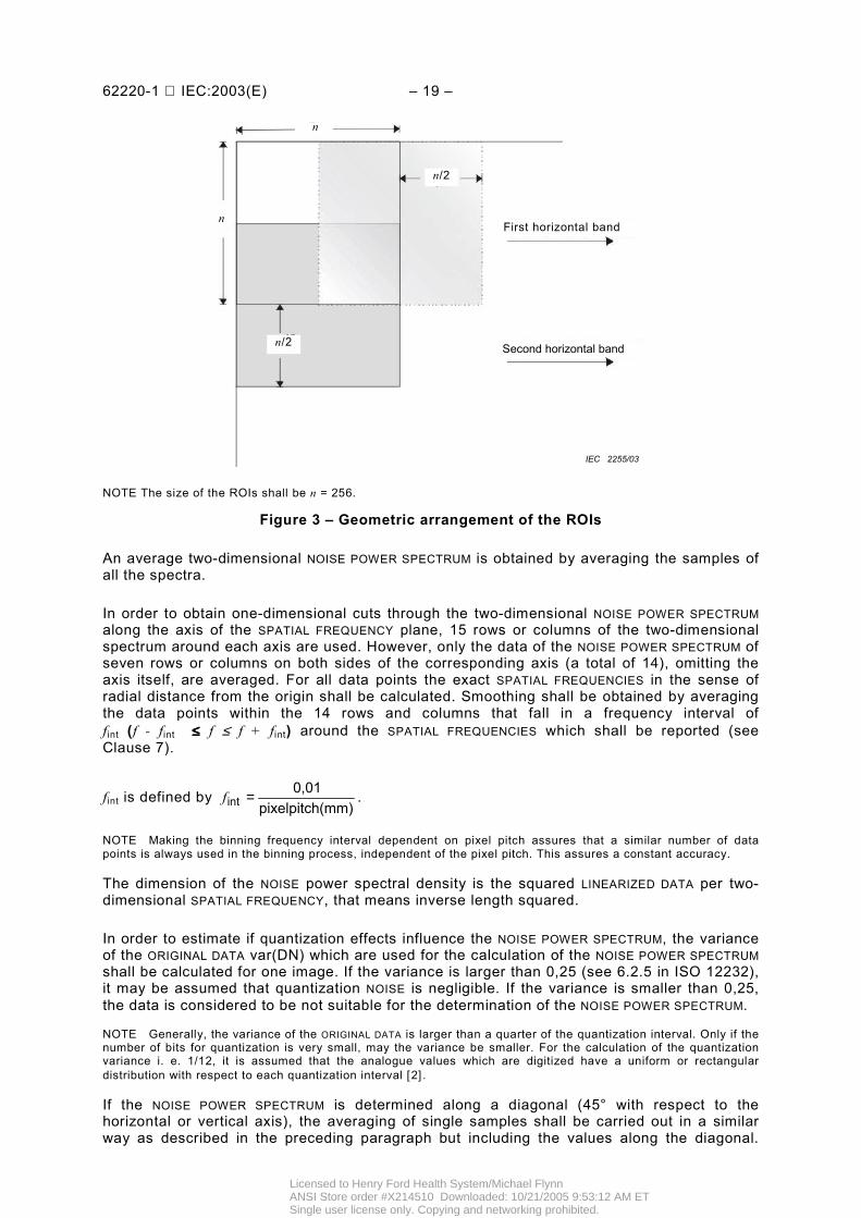
The portion of the uniformly exposed area of the digital X-ray detector used for NPS analysisshall be divided into square areas, called ROIs. Each ROI for calculating an individual samplefor the NOISE POWER SPECTRUM shall be 256 × 256 PIXELS in size. These areas shall overlap by128 PIXELS in both, the horizontal and vertical direction (see Figure 3). Let the first area be theone in the upper left corner of the total region analysed. The next is produced by moving therectangular area 128 PIXELS in the horizontal direction to the right-hand side, generating asecond area, which overlaps half with the first one. The next is defined by moving the secondone by 128 PIXELS again. This is repeated up to the end of the first horizontal “band“. Startingagain at the left-hand side of the image and simultaneously moving by 128 PIXELS in thevertical direction, a second horizontal “band“ is generated. The movement in the verticaldirection generates further bands until the whole area of about 125 mm × 125 mm is coveredby ROIs.
Trend removal may be performed by fitting a two-dimensional second-order polynomial to theLINEARIZED DATA of each complete image used for calculating the spectra and subtracting thisfunction (S(xi,yj), see equation (4)) from the LINEARIZED DATA. Without applying any windowing,the two-dimensional Fourier transform is calculated for every ROI.
The two-dimensional Fourier transform is applied using equation (4). Starting with equation3.44 as given in the Handbook of Medical Imaging I [4], the working equation for thedetermination of the NOISE POWER SPECTRUM according to this standard is :
( )2
256
1
256
11out ))(2exp(),(),(
256256),( jkin
jjiji
i
M
mkn yvxuiyxSyxI
MyxvuW +−−⋅⋅
∆∆= ∑∑∑
===π (4)
where
∆x∆y is the pixel spacing in respectively the horizontal and vertical direction;
M is the number of ROIs;I(xi,yj) is the LINEARIZED DATA;S(xi,yj) is the optionally fitted two-dimensional polynomial.
Licensed to Henry Ford Health System/Michael FlynnANSI Store order #X214510 Downloaded: 10/21/2005 9:53:12 AM ETSingle user license only. Copying and networking prohibited.
62220-1 IEC:2003(E) – 19 –
First horizontal band
Second horizontal band
n/2
n
n
n/2
IEC 2255/03
NOTE The size of the ROIs shall be n = 256.
Figure 3 – Geometric arrangement of the ROIs
An average two-dimensional NOISE POWER SPECTRUM is obtained by averaging the samples ofall the spectra.
In order to obtain one-dimensional cuts through the two-dimensional NOISE POWER SPECTRUMalong the axis of the SPATIAL FREQUENCY plane, 15 rows or columns of the two-dimensionalspectrum around each axis are used. However, only the data of the NOISE POWER SPECTRUM ofseven rows or columns on both sides of the corresponding axis (a total of 14), omitting theaxis itself, are averaged. For all data points the exact SPATIAL FREQUENCIES in the sense ofradial distance from the origin shall be calculated. Smoothing shall be obtained by averagingthe data points within the 14 rows and columns that fall in a frequency interval offint (f - fint ≤≤≤≤ f ≤ f + fint) around the SPATIAL FREQUENCIES which shall be reported (seeClause 7).
fint is defined by (mm)pixelpitch
0,01int =f .
NOTE Making the binning frequency interval dependent on pixel pitch assures that a similar number of datapoints is always used in the binning process, independent of the pixel pitch. This assures a constant accuracy.
The dimension of the NOISE power spectral density is the squared LINEARIZED DATA per two-dimensional SPATIAL FREQUENCY, that means inverse length squared.
In order to estimate if quantization effects influence the NOISE POWER SPECTRUM, the varianceof the ORIGINAL DATA var(DN) which are used for the calculation of the NOISE POWER SPECTRUMshall be calculated for one image. If the variance is larger than 0,25 (see 6.2.5 in ISO 12232),it may be assumed that quantization NOISE is negligible. If the variance is smaller than 0,25,the data is considered to be not suitable for the determination of the NOISE POWER SPECTRUM.
NOTE Generally, the variance of the ORIGINAL DATA is larger than a quarter of the quantization interval. Only if thenumber of bits for quantization is very small, may the variance be smaller. For the calculation of the quantizationvariance i. e. 1/12, it is assumed that the analogue values which are digitized have a uniform or rectangulardistribution with respect to each quantization interval [2] .
If the NOISE POWER SPECTRUM is determined along a diagonal (45° with respect to thehorizontal or vertical axis), the averaging of single samples shall be carried out in a similarway as described in the preceding paragraph but including the values along the diagonal.
Licensed to Henry Ford Health System/Michael FlynnANSI Store order #X214510 Downloaded: 10/21/2005 9:53:12 AM ETSingle user license only. Copying and networking prohibited.

– 20 – 62220-1 IEC:2003(E)
These measurements at 45° may also require averaging of adjacent 45° cuts in order toimprove the precision of NPS determination.
6.3.3 Determination of the MODULATION TRANSFER FUNCTION (MTF)
The pre-sampling MODULATION TRANSFER FUNCTION shall be determined along two mutuallyperpendicular axes which are parallel to the rows or to the columns of the IMAGE MATRIX,respectively.
For the determination of the MTF, the complete length of the edge spread function (ESF) asdefined by the ROI shown in Figure 1 shall be used.
The integer number N of lines (i.e. rows or columns) leading to a lateral shift of the edge inline direction which most closely matches the value of 1 PIXEL is determined. Differentmethods may be applied. One is to determine the angle α between the edge and the columnsor rows of the IMAGE MATRIX and to calculate N as N = round (1/tanα), where “round” denotesthe rounding to the nearest integer value. N should be accurate to integer precision.
NOTE The range of values for the angle α means that N is between about 20 and 40.
The pixel values of the LINEARIZED DATA (see 6.3.1) of N consecutive lines (i.e. rows orcolumns) across the edge are used to generate an oversampled edge profile or (ESF). Thevalue of the first PIXEL in the first line gives the first data point in the oversampled ESF, thefirst PIXEL in the second line the second data point, and the first PIXEL in the Nth line the N th
data point. This procedure is repeated for the other PIXELS in the N consecutive lines, forexample, the value of the second PIXEL in the first line gives the (N + 1)th data point, thesecond PIXEL in the second line the (N + 2)th data point, etc.
The sampling distance in the oversampled ESF is assumed to be constant and is given by thePIXEL spacing ∆x divided by N, i.e. ESF(xn) with xn = n(∆x/N). The oversampled ESF isdifferentiated using a [–1, 0, 1] or [–0,5, 0, 0,5] kernel yielding the oversampled line spreadfunction LSF. The spectral smoothing effect of the finite-element differentiation may becorrected [6]. A digital Fourier transform of the line-spread function is calculated, and themodulus of this Fourier transform yields the MTF. The MTF is normalized to its value at zerofrequency. Since the distance of the individual PIXELS to the edge is calculated along the linedirection and not in a direction perpendicular to the edge, a frequency axis scaling (scalingfactor: 1/cosα) may be performed for correction.
NOTE The error of the SPATIAL FREQUENCY is ≤ 0,1 % if no correction by 1/cosα is done.
To calculate the average MTF, this procedure is repeated for other groups of N consecutivelines along the edge. Alternatively, and especially suited for noisier images, the average of alledge spread functions is determined, and the MTF is calculated based on this average ESF.
To obtain the MTF at the SPATIAL FREQUENCIES which shall be reported (see Clause 7), binningof the data points in a frequency interval of fint mm–1 (f – fint ≤ f ≤ f + fint, see 6.3.2 for fint)around these SPATIAL FREQUENCIES shall be performed.
7 Format of conformance statement
When stating the DETECTIVE QUANTUM EFFICIENCY, the following parameters shall be stated:
– RADIATION QUALITY according to Table 1;– exposure (AIR KERMA);– distance between FOCAL SPOT and DETECTOR SURFACE if less than 1,5 m;– deviations from recommended centred geometry (see 4.5);– method used for MTF determination and its validation, if a method different from the
standardized edge method is used;
Licensed to Henry Ford Health System/Michael FlynnANSI Store order #X214510 Downloaded: 10/21/2005 9:53:12 AM ETSingle user license only. Copying and networking prohibited.
62220-1 IEC:2003(E) – 21 –
– ambient climatic conditions.
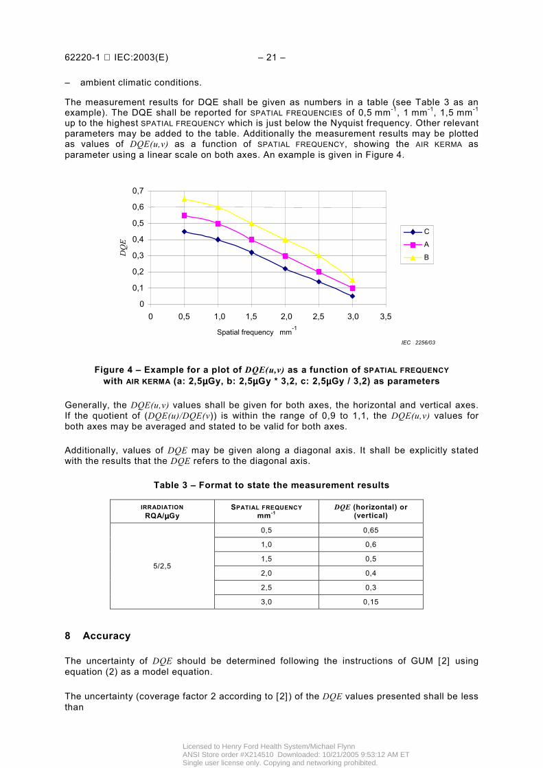
The measurement results for DQE shall be given as numbers in a table (see Table 3 as anexample). The DQE shall be reported for SPATIAL FREQUENCIES of 0,5 mm-1, 1 mm-1, 1,5 mm-1
up to the highest SPATIAL FREQUENCY which is just below the Nyquist frequency. Other relevantparameters may be added to the table. Additionally the measurement results may be plottedas values of DQE(u,v) as a function of SPATIAL FREQUENCY, showing the AIR KERMA asparameter using a linear scale on both axes. An example is given in Figure 4.
0
0,1
0,2
0,3
0,4
0,5
0,6
0,7
0 0,5 1,0 1,5 2,0 2,5 3,0 3,5
Spatial frequency mm-1
DQ
E
C
A
B
IEC 2256/03
Figure 4 – Example for a plot of DQE(u,v) as a function of SPATIAL FREQUENCYwith AIR KERMA (a: 2,5µµµµGy, b: 2,5µµµµGy * 3,2, c: 2,5µµµµGy / 3,2) as parameters
Generally, the DQE(u,v) values shall be given for both axes, the horizontal and vertical axes.If the quotient of (DQE(u)/DQE(v)) is within the range of 0,9 to 1,1, the DQE(u,v) values forboth axes may be averaged and stated to be valid for both axes.
Additionally, values of DQE may be given along a diagonal axis. It shall be explicitly statedwith the results that the DQE refers to the diagonal axis.
Table 3 – Format to state the measurement results
IRRADIATIONRQA/µµµµGy
SPATIAL FREQUENCYmm-1
DQE (horizontal) or(vertical)
0,5 0,65
1,0 0,6
1,5 0,5
2,0 0,4
2,5 0,3
5/2,5
3,0 0,15
8 Accuracy
The uncertainty of DQE should be determined following the instructions of GUM [2] usingequation (2) as a model equation.
The uncertainty (coverage factor 2 according to [2] ) of the DQE values presented shall be lessthan
Licensed to Henry Ford Health System/Michael FlynnANSI Store order #X214510 Downloaded: 10/21/2005 9:53:12 AM ETSingle user license only. Copying and networking prohibited.

– 22 – 62220-1 IEC:2003(E)
∆(DQE(u)) = ± 0,06 or
∆(DQE(u))/DQE(u) = ± 0,10,
whichever is greater.
The uncertainty should be stated in the data sheets.
Licensed to Henry Ford Health System/Michael FlynnANSI Store order #X214510 Downloaded: 10/21/2005 9:53:12 AM ETSingle user license only. Copying and networking prohibited.
62220-1 IEC:2003(E) – 23 –
Annex A (normative)
Determination of LAG EFFECTS
A.1 Test of additive LAG EFFECTS
To test the magnitude of additive LAG EFFECTS, the following test procedure shall beperformed.
1) Following the method as described in 4.6.6, carry out an IRRADIATION of the edge TESTDEVICE. Ensure that the object is properly aligned with the beam as specified in 4.6.6. TheIRRADIATION shall be made at the “normal” exposure level as described in 4.6.1.
2) Create an image resulting from the IRRADIATION of step 1 following the method proposedby the manufacturer.
3) Follow whatever steps are part of the proposed method for the treatment of the digital X-ray detector between IRRADIATIONS.
4) Without further irradiating the DETECTOR SURFACE, create a second image following themethod of step 2.
5) Record the time between the first (irradiated) and the second (non-irradiated) reading ofthe digital X-ray detector. The larger of this time and the time determined in Clause A.2shall be the minimum time between successive images used for the determination of theCONVERSION FUNCTION, the NOISE POWER SPECTRUM and the MTF.
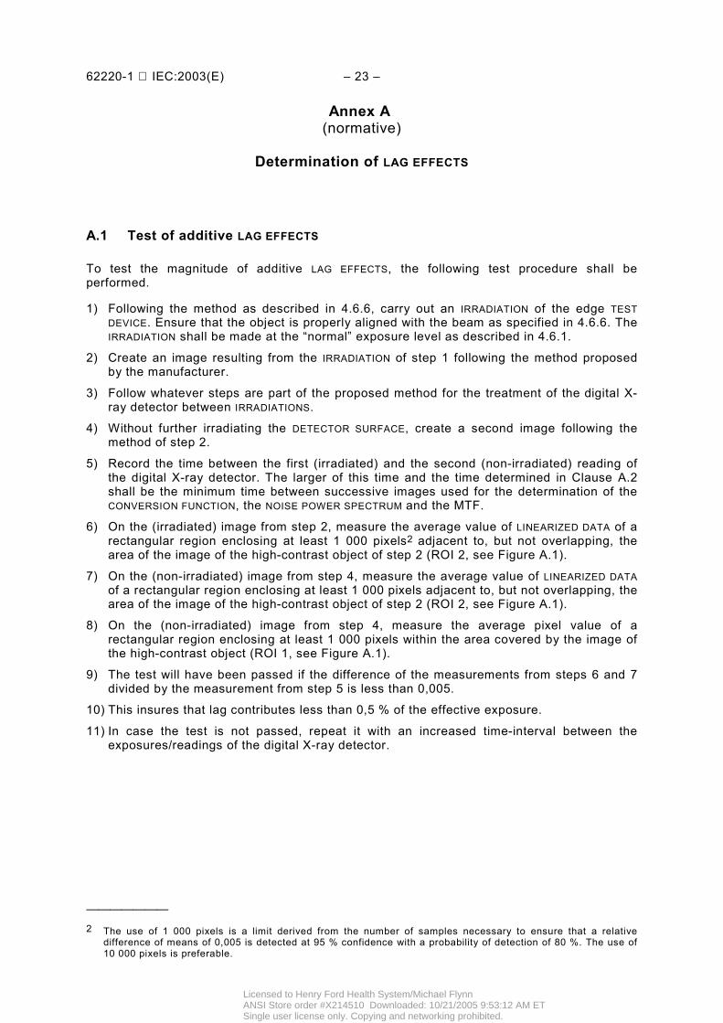
6) On the (irradiated) image from step 2, measure the average value of LINEARIZED DATA of arectangular region enclosing at least 1 000 pixels2 adjacent to, but not overlapping, thearea of the image of the high-contrast object of step 2 (ROI 2, see Figure A.1).
7) On the (non-irradiated) image from step 4, measure the average value of LINEARIZED DATAof a rectangular region enclosing at least 1 000 pixels adjacent to, but not overlapping, thearea of the image of the high-contrast object of step 2 (ROI 2, see Figure A.1).
8) On the (non-irradiated) image from step 4, measure the average pixel value of arectangular region enclosing at least 1 000 pixels within the area covered by the image ofthe high-contrast object (ROI 1, see Figure A.1).
9) The test will have been passed if the difference of the measurements from steps 6 and 7divided by the measurement from step 5 is less than 0,005.
10) This insures that lag contributes less than 0,5 % of the effective exposure.
11) In case the test is not passed, repeat it with an increased time-interval between theexposures/readings of the digital X-ray detector.
———————2 The use of 1 000 pixels is a limit derived from the number of samples necessary to ensure that a relative
difference of means of 0,005 is detected at 95 % confidence with a probability of detection of 80 %. The use of10 000 pixels is preferable.
Licensed to Henry Ford Health System/Michael FlynnANSI Store order #X214510 Downloaded: 10/21/2005 9:53:12 AM ETSingle user license only. Copying and networking prohibited.

– 24 – 62220-1 IEC:2003(E)
ROI 1 ROI 2
IEC 2257/03
Figure A.1 – Definition of the ROIs
A.2 Test of multiplicative LAG EFFECTS
To test the magnitude of multiplicative LAG EFFECTS, the following test procedure shall beperformed.
1) Following the method described in 4.6.1, carry out an IRRADIATION without an object in thebeam, using the normal exposure level.
2) Create an image resulting from the IRRADIATION of step 1 (image1, irradiated, no TESTDEVICE) following the method proposed by the manufacturer.
3) Follow whatever steps are part of the proposed method for the treatment of the digital X-ray detector between IRRADIATIONS.
4) Following the method described in 4.6.6, carry out an IRRADIATION of the edge TESTDEVICE. Ensure that the object is properly aligned with the beam as specified in 4.6.6. TheIRRADIATION shall be made at the “normal” exposure level as determined in 4.6.1.
5) Create an image resulting from the IRRADIATION of step 4 (image2) following the methodproposed by the manufacturer.
6) Follow whatever steps are part of the proposed method for the treatment of the digitalX-ray detector between IRRADIATIONS.
7) Following the method described in 4.6.1, carry out a second IRRADIATION without an objectin the beam, using the normal exposure level.
8) Create an image resulting from the IRRADIATION of step 7 (image3, irradiated, no TESTdevice) following the method proposed by the MANUFACTURER. Record the time betweenthe second (irradiated, TEST DEVICE) and the third (irradiated, no TEST DEVICE) reading ofthe digital X-ray detector. The larger of this and the time determined in Clause A.1 shallbe the minimum time between successive images used for the determination of theCONVERSION FUNCTION, the NOISE POWER SPECTRUM and the MTF.
9) On the images 1 and 3, respectively, measure the average value of LINEARIZED DATA of arectangular region enclosing at least 1 000 pixels within the area covered by the image ofthe high-contrast object (ROI 1, see Figure A.1).
Licensed to Henry Ford Health System/Michael FlynnANSI Store order #X214510 Downloaded: 10/21/2005 9:53:12 AM ETSingle user license only. Copying and networking prohibited.

62220-1 IEC:2003(E) – 25 –
10) On the images 1 and 3, respectively, measure the average value of LINEARIZED DATA of arectangular region enclosing at least 1 000 pixels which is adjacent to, but notoverlapping, the image of the high-contrast object (ROI 2, see Figure A.1).
11) The test will have been passed if
005,0
2Image3Image1
)Image3Image3()Image1Image1(ROI2ROI2
ROI2ROI1ROI2ROI1 ≤+
−−−
This insures that lag contributes less than 0,5% of the effective exposure.
If the test is not passed, repeat it with an increased time-interval between the exposuresof the digital X-ray detector.
Licensed to Henry Ford Health System/Michael FlynnANSI Store order #X214510 Downloaded: 10/21/2005 9:53:12 AM ETSingle user license only. Copying and networking prohibited.

– 26 – 62220-1 IEC:2003(E)
Annex B (normative)
Terminology – Index of defined terms
IEC 60788 ……………………………………………………………………………………. rm-..-..Shortened term ………………………………………………………………………….…… rm-..-..sTerm defined in this standard.............................................................................. 3.xx
ADDED FILTER ……………………….………………………………………………………… rm-35-02AIR KERMA ……………………………………………………………………….................. rm-13-11ANTI-SCATTER GRID…………………………………………………………………………… rm-32-06AUTOMATIC EXPOSURE CONTROL ……………………………………………………………. rm-36-46CENTRAL AXIS………………………………………………………………………………….. 3.1COMPUTED TOMOGRAPHY rm-41-20CONSTANT POTENTIAL HIGH-VOLTAGE GENERATOR ………………………………………... rm-21-06CONVERSION FUNCTION………………………………………………………………………. 3.2DETECTIVE QUANTUM EFFICIENCY, DQE(u,v)………………………………………………. 3.3DETECTOR SURFACE.............................................................................................. 3.4DIAPHRAGM ………………………………………………………………………................. rm-37-29DIGITAL X-RAY IMAGING DEVICE............................................................................... 3.5FOCAL SPOT ………………………………………………………….……………………….. rm-20-13sHALF-VALUE LAYER ………………………………………………………………….…..……. rm-13-42IMAGE MATRIX………………………………………………………………………………….. 3.6IMAGE RECEPTOR PLANE………………………………………………………………………. rm-37-15IRRADIATION …………………………………………………………………………..…….... rm-12-09IRRADIATION TIME……………………………………………………………………………… rm-36-11LAG EFFECT……………………………………………………………………………………. 3.7LINEARIZED DATA………………………………………………………………………………. 3.8MODULATION TRANSFER FUNCTION, MTF(u,v)……………………………………………… 3.9NOISE…………………………………………………………………………………………… 3.10NOISE POWER SPECTRUM (NPS), W(u,v)…………………………………………………… 3.11NOMINAL FOCAL SPOT VALUE …………………………………………………….…….……. rm-20-14ORIGINAL DATA, DN…………………………………………………………………………… 3.3.112PENUMBRA …………………………………………………………………………………….. rm-37-08PERCENTAGE RIPPLE …………………………………………………………………………. rm-36-17PHOTON FLUENCE……………………………………………………………………………… 3.13RADIATION APERTURE ………………………………………………………………………… rm-37-26RADIATION BEAM …………………………………………………………………………...…. rm-37-05RADIATION DETECTOR ………………………………………………………………………… rm-51-01RADIATION METER …………………………………………………………...............……… rm-50-01RADIATION QUALITY……………………………………………………………………………. rm-13-28RADIATION SOURCE ASSEMBLY ………………………………………………………………. rm-20-05RAW DATA ……………………………………………………………………………………… 3.14SCATTERED RADIATION ………………………………………………………………..……... rm-11-13SPATIAL FREQUENCY, u or v ………………………………………………………………… 3.15TEST DEVICE …………………………………………………………………………………... rm-71-04X-RAY EQUIPMENT …………………………………………………………….………….…… rm-20-20X-RAY GENERATOR…………………………………………………………………………….. rm-20-17X-RAY IMAGE INTENSIFIER ……………………………………………..……………….….… rm-32-39X-RAY TUBE ……………………………………………………………………..…………….. rm-22-03X-RAY TUBE CURRENT ………………………………………………………………………... rm-36-07X-RAY TUBE VOLTAGE............................................................................................. rm-36-02
Licensed to Henry Ford Health System/Michael FlynnANSI Store order #X214510 Downloaded: 10/21/2005 9:53:12 AM ETSingle user license only. Copying and networking prohibited.

62220-1 IEC:2003(E) – 27 –
Annex C (informative)
Calculation of the input NOISE POWER SPECTRUM
The input NOISE POWER SPECTRUM is equal to the incoming PHOTON FLUENCE (equation 2.134 inthe Handbook of Medical Imaging I, [4]).
QvuW =),(in (5)
whereQ is the PHOTON FLUENCE, i.e. the number of exposure quanta per unit area (1/mm²). Q
depends on the spectrum of the X-radiation and the AIR KERMA level:
2inaaa )/)(( SNRKdEKEKQ ⋅=Φ⋅= ∫ (6)
where
Ka is AIR KERMA, unit: µGy;E is X-ray energy, unit: keV;
Φ(E)/Ka is spectral X-ray fluence per AIR KERMA, unit: 1/(mm2⋅keV⋅µGy);
SNRin2 is squared signal-to-NOISE ratio per AIR KERMA, unit: 1/( mm2⋅µGy).
The values as given in Table 2 are calculated using the computer programme SPEVAL. Theuse of other programmes may result in slightly different values. The data and the softwareprogram needed for the calculation of SNRin
2 have been provided by Dr. H. Kramer of PTB [7].
X-ray spectra:Calculated for a tungsten anode, 12° anode angle, 2,5 mm Al filter, 1 m air, for kV incrementsof 1 kV, according to Iles [8]. The spectra include characteristic X-rays.
AIR KERMA:Calculated using data of P.D. Higgins et al.[9]
Interaction coefficients:Data taken from the XCOM data base provided by NIST [10].
Licensed to Henry Ford Health System/Michael FlynnANSI Store order #X214510 Downloaded: 10/21/2005 9:53:12 AM ETSingle user license only. Copying and networking prohibited.

– 28 – 62220-1 IEC:2003(E)
Bibliography
Referenced publications
[1] ICRU Report 54:1996, Medical Imaging – The Assessment of Image Quality.
[2] ISO Guide to the expression of uncertainty in measurement, 1993.
[3] METZ, EC., WAGNER, RF., DOI, K., BROWN, DG., NISHIKAWA, RM., MYERS, KJ.Toward consensus on quantitative assessment of medical imaging systems. Med. Phys.,1995, 22, p.1057-1061.
[4] BEUTEL, J, KUNDEL, HL., VAN METTER, RL. Editors: Handbook of medical imaging.Vol. 1: Physics and Psychophysics. SPIE, 2000.
[5] TAPIOVAARA, MJ. and WAGNER, RF. SNR and DQE analysis of broad spectrum X-rayimaging. Phys. Med. Biol., 1985, 30, p. 519-529, and corrigendum Phys. Med. Biol.1986, 31, p.195.
[6] CUNNINGHAM, IA. and FENSTER, A. A method for modulation transfer functiondetermination from edge profiles with correction for finite-element differentiation.Med.Phys. 14, 1987, p. 533-537.
[7] SPEVAL software package version of Jan. 1995 (H. Kramer of PTB)
[8] ILES, WJ. Computation of bremsstrahlung X-ray spectra over an energy range 15 keVto 300 keV. National Radiological Protection Board Report 204, London, HMSO, 1987
[9] HIGGINS, PD. et al. Mass Energy-Transfer and Mass Energy-Absorption Coefficients,Including In-Flight Positron Annihilation for Photon Energies 1keV to 100MeV. NISTIR4812, National Institute of Standards and Technology, Gaithersburg USA (1992).
[10] BERGER, MJ. and Hubbell, JH. XCOM: Photon Cross Sections Database, NISTStandard Reference Database 8, National Institute of Standards and Technology,Gaithersburg USA.
Other literature of interest
DAINTY, JC. and SHAW, R. Image Science. Academic Press, London, 1974, ch. 5, p. 153.
DAINTY, JC. and SHAW, R. Image Science. Academic Press, London, 1974, ch.8, p. 312.
DAINTY, JC. and SHAW, R. Image Science. Academic Press, London, 1974, ch.8, p. 280.
SHAW, R. The Equivalent Quantum Efficiency of the Photographic Process. J. Ph. Sc., 1963,11, p.199-204 .
STIERSTORFER, K., SPAHN, M. Self-normalizing method to measure the detective quantumefficiency of a wide range of X-ray detectors. Med. Phys., 1999, 26, p.1312-1319.
HILLEN, W., SCHIEBEL, U., ZAENGEL, T. Imaging performance of digital phosphor system.Med.Phys., 1987, 14, p. 744-751.
Licensed to Henry Ford Health System/Michael FlynnANSI Store order #X214510 Downloaded: 10/21/2005 9:53:12 AM ETSingle user license only. Copying and networking prohibited.

62220-1 IEC:2003(E) – 29 –
CUNNINGHAM, IA., in Standard for Measurement of Noise Power Spectra, AAPM Report,December 1999
SAMEI, E., FLYNN, MJ., REIMANN, D.A. A method for measuring the presampled MTF ofdigital radiographic systems using an edge test device. Med. Phys., 1998, 25, p.102 – 113.
GRANFORS, PR., AUFRICHTIG, R. DQE(f) of an Amorphous Silicon Flat Panel X-rayDetector: Detector Parameter Influences.
CUNNINGHAM,IA.: Degradation of the Detective Quantum Efficiency due to a Non-UnityDetector Fill Factor. Proceedings SPIE, 3032, 1997, p. 22-31.
SIEWERDSEN, JH., ANTONUK, LE., EL-MOHRI, Y., YORKSTON, J., HUANG, W., andCUNNINGHAM, IA. Signal, noise power spectrum, and detective quantum efficiency ofindirect-detection flat-panel imagers for diagnostic radiology. Med. Phys., 1998, 25, p.614 –628.
DOBBINS III, JT. Effects of undersampling on the proper interpretation of modulation transferfunction, noise power spectra, and noise equivalent quanta of digital imaging systems. Med.Phys., 1995, 22, p.171 –181.
DOBBINS III, JT., ERGUN, DL., RUTZ, L., HINSHAW, DA., BLUME, H., and CLARK, DC.DQE(f) of four generations of computed radiography acquisition devices. Med. Phys., 1995,22, p.1581 – 1593
SAMEI, E., FLYNN, M.J., CHOTAS, H.G., DOBBINS III, J.T. DQE of direct and indirect digitalradiographic systems. Proceedings of SPIE, Vol. 4320, 2001, p.189-197.
IEC 61262-5:1994, Medical electrical equipment – Characteristics of electro-optical X-rayimage intensifiers – Part 5: Determination of the detective quantum efficiency
ISO 12233:2000, Photography – Electronic still-picture cameras – Resolution measurements
ISO 15529:1999, Optics and optical instruments – Optical transfer function – Principles ofmeasurement of modulation transfer function (MTF) of sampled imaging systems
ICRU Report 41, 1986:Modulation Transfer Function of Screen-Film-Systems
DOBBINS III, JT. Image Quality Metrics for Digital Systems. In: Handbook of Medical Imaging,Vol. I, Ed. by J. Beutel, H.L. Kundel, and R.L. Van Metter, SPIE Press, 2000.
___________
Licensed to Henry Ford Health System/Michael FlynnANSI Store order #X214510 Downloaded: 10/21/2005 9:53:12 AM ETSingle user license only. Copying and networking prohibited.

Licensed to Henry Ford Health System/Michael FlynnANSI Store order #X214510 Downloaded: 10/21/2005 9:53:12 AM ETSingle user license only. Copying and networking prohibited.

Standards Survey
The IEC would like to offer you the best quality standards possible. To make sure that wecontinue to meet your needs, your feedback is essential. Would you please take a minuteto answer the questions overleaf and fax them to us at +41 22 919 03 00 or mail them tothe address below. Thank you!
Customer Service Centre (CSC)
International Electrotechnical Commission3, rue de Varembé1211 Genève 20Switzerland
or
Fax to: IEC/CSC at +41 22 919 03 00
Thank you for your contribution to the standards-making process.
Non affrancareNo stamp required
Nicht frankierenNe pas affranchir
A Prioritaire
RÉPONSE PAYÉE
SUISSE
Customer Service Centre (CSC)International Electrotechnical Commission3, rue de Varembé1211 GENEVA 20Switzerland
Licensed to Henry Ford Health System/Michael FlynnANSI Store order #X214510 Downloaded: 10/21/2005 9:53:12 AM ETSingle user license only. Copying and networking prohibited.

Q1 Please report on ONE STANDARD andONE STANDARD ONLY . Enter the exactnumber of the standard: (e.g. 60601-1-1)
.............................................................
Q2 Please tell us in what capacity(ies) youbought the standard (tick all that apply).I am the/a:
purchasing agent R
librarian R
researcher R
design engineer R
safety engineer R
testing engineer R
marketing specialist R
other.....................................................
Q3 I work for/in/as a:(tick all that apply)
manufacturing R
consultant R
government R
test/certification facility R
public utility R
education R
military R
other.....................................................
Q4 This standard will be used for:(tick all that apply)
general reference R
product research R
product design/development R
specifications R
tenders R
quality assessment R
certification R
technical documentation R
thesis R
manufacturing R
other.....................................................
Q5 This standard meets my needs:(tick one)
not at all R
nearly R
fairly well R
exactly R
Q6 If you ticked NOT AT ALL in Question 5the reason is: (tick all that apply)
standard is out of date R
standard is incomplete R
standard is too academic R
standard is too superficial R
title is misleading R
I made the wrong choice R
other ....................................................
Q7 Please assess the standard in thefollowing categories, usingthe numbers:(1) unacceptable,(2) below average,(3) average,(4) above average,(5) exceptional,(6) not applicable
timeliness .............................................quality of writing....................................technical contents.................................logic of arrangement of contents ..........tables, charts, graphs, figures ...............other ....................................................
Q8 I read/use the: (tick one)
French text only R
English text only R
both English and French texts R
Q9 Please share any comment on anyaspect of the IEC that you would likeus to know:
............................................................
............................................................
............................................................
............................................................
............................................................
............................................................
............................................................
............................................................
............................................................
............................................................
............................................................
............................................................
Licensed to Henry Ford Health System/Michael FlynnANSI Store order #X214510 Downloaded: 10/21/2005 9:53:12 AM ETSingle user license only. Copying and networking prohibited.

Licensed to Henry Ford Health System/Michael FlynnANSI Store order #X214510 Downloaded: 10/21/2005 9:53:12 AM ETSingle user license only. Copying and networking prohibited.

ISBN 2-8318-7200-6
-:HSMINB=]\WUUV:ICS 11.040.50
Typeset and printed by the IEC Central OfficeGENEVA, SWITZERLAND
Licensed to Henry Ford Health System/Michael FlynnANSI Store order #X214510 Downloaded: 10/21/2005 9:53:12 AM ETSingle user license only. Copying and networking prohibited.