international · international please direct enquires to: yardmaster international cahore road...
TRANSCRIPT

INTERNATIONAL Please direct enquires to: Yardmaster International Cahore Road Draperstown BT45 7AP. Tel: 028 7962 8449
Demandes de renseignements à: TRIGANO JARDIN Service Commercial Usine du Boulay 41 170 Cormenon Mondoubleau Tel: (02) 54 73 55 55
Bitte alle Anfragen an: I.D.B. Oststraße 152 40210 Düsseldorf Tel: 02 11 36 28 57
0112


ROOF BEAM SUB-ASSEMBLY 1. Separate and lay flat all roof beams, 50213, 50219 and all roof beam splice plates 50200. 2. Place all roof beams in pairs and set back to back with the sloping sides facing down and away to
form a "V" angle head. 3. Overlap one of the 50219 roof beams with one of the 50213 roof beams on the second and third
holes on each beam as shown. Overlap other end of 50213 with another 50219. 4. Repeat step three. 5. Place a pair of roof beams back to back and splice together with splice plates 50200 on either side
using 4 bolts and nuts (bag 9). 6. Construct two more of these assemblies.
ASSEMBLAGE DES POUTRES DE TOIT 1. SEPARER ET POSER A PLAT TOUTES LES POUTRES FAITIERES 50213 ET 50219, PUIS
POSITIONNER LES EQUERRES DE POUTRES 50200 PERMETTANT L’ASSEMBLAGE. 2. METTRE PAR PARIE TOUTES LES POUTRES DE TOIT DOS A DOS, LES PROFILES DEVANT
ETRE TOURNES VERS L'EXTERIEUR. 3. ASSEMBLER LES POUTRES DE TOIT 50219 ET 50213 COMME INDIQUE SUR LE SCHEMA CI-
DESSOUS, LAISSANT LIBRE LE DEUXIEME ET LE TROISIEME TROU. 4. REPETER (3). 5. FIXER LES EQUERRES DE POUTRE 50200 L'AIDE DES 4 BOULONS ET ECROUS (POCHETTE
NO.9). VOUS ASSURER QU ‘EN AJUSTANT LES EQUERRES, 2 TROUS SERONT LAISSESLIBRES SUR LES POUTRES LONGUES, ET 2 TROUS SUR LES POUTRES COURTES.
6. REALISER CE TYPE D ASSEMBLAGE POUR LES 3 POUTRES DE TOIT.


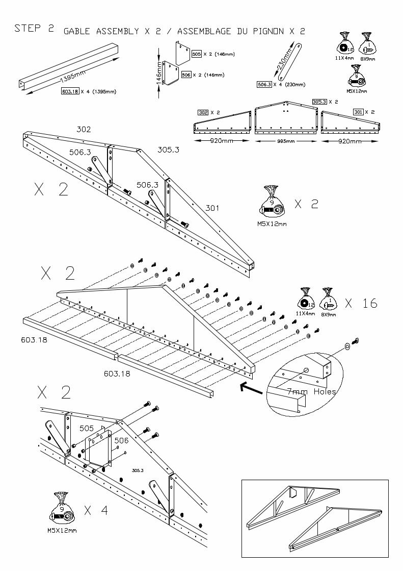
FRONT FRAME POST. 1. Select one 41302 and one 41307, fix together as shown with the front frame braces; 41303 using
screws (bag 1) and (bag 12). 2. Repeat for other side of front frame.
ALWAYS ENSURE HOLES TO LOCATE HINGES ARE TOWARD OUTSIDE OF FRONTFRAME. ENSURE COMPLETED FRAME IS SQUARE
FRONT FRAME.
1. Line up holes on both 41304's as shown (fig 1). 2. Fix into channel both 41305's with the third hole in from either end lining up (fig 2). 3. Central to this channel line up 41306. 4. Fix together at overlaps with screws (bag 1) (fig 3). 5. Attach front frame posts to both ends in order to complete the front frame assembly.
PROFILE DE PILLER DE FACADE 1. ASSEMBLER LES PROFILES D'ANGLE 41302 ET 41307 COMME INDIQUE CI-DESSOUS AVEC
LES PROFILES DE FACADE, A L'AIDE DE LA VISSERIE DES POCHETTES NO.1 ET NO.12. 2. IDEM POUR LE PILIER DE FACADE DROIT.
TOUJOURS S'ASSURER QUE LES TROUS DEVANT RECEVOIR LES GONDS SOILENT SUR LESPROFILES EXTERIEURS DU PILiER.
STRUCTURE FRONTALE
1. SUPERPOSER LES DEUX PROFILES 41304 COMME INDIQUE (FIG 1). 2. FIXER AU TROISIEME TROU, A L'INTERIEUR DU PROFILE DE FACADE, LES DEUX
PROFILES 41305 (FIG 2). 3. PLACER LE PROFILE CENTRAL 41306. 4. VISSER L'ENSEMBLE AVEC LA VISSERIE DE LA POCHETTE NO.1 (FIG 3). 5. LA FIGURE 3 MONTRE L'ENSEMBLE DE LA STRUCTURE FRONTALE ASSEMBLEE AU PILIER DE FACADE.


BACK SECTION ASSEMBLY. 1. Overlap and attach two back base rails; 41101, to back intermediate base rail; 41104, on inside of
either end of 41104 using screws (bag 1). 2. Fix 2 standard uprights; 41301, as shown to centre of back base rail overlaps using screws (bag 2)
and spire nuts (bag 10).
ASSEMBLAGE DE LA STRUCTURE ARRIERE 1. SUPERPOSER ET FIXER AUX DEUX POUTRES RENFORCEES 41101 LE RAIL DE BASE 41104,
A L'AIDE DE LA VISSERIE DE LA POCHETTE NO. 1. 2. FIXER LES DEUX PROFILES D'ANGLE 41301 COMME INDIQUE CI-DESSOUS AU CENTRE DU RAIL DE BASE, A L'AIDE DE LA VISSERIE DE LA POCHETTE NO. 2 ET DES ECROUS DE LA POCHETTE NO. 10.


BACK SECTION ASSEMBLY. 3. Fix left/right back braces; 41201, and intermediate back brace; 41205 to centre hole in standard
upright; 41301. 4. Fit a 10118 wall panel to side of back section; starting from position: : 4th hole from edge of base rail, : 3rd hole along L/R back brace, using screws (bag 1) and washers (bag 12). 5. Fit a further 10118 wall panel followed by a 10218 wall panel in centre of section followed by two
further 10118 panels. Secure with screws and washers (bags 1 & 12) to complete back section.
ASSEMBLAGE DE LA STRUCTURE ARRIERE 3. FIXER LES CONTREVENTEMENTS ARRIERES GAUCHE/DROIT, 41201 ET
CONTREVENTEMENT CENTRALE ARRIERE, 41205 AU TROU CENTRAL DANS LE MONTANTSRANDARD, 41301.
4. FIXER LES PANNEAUX MURAUX (101.18) A LA STRUCTURE DE PROFILE ARRIERE COMME
SUIT: - 4 EME TROU DU BOUT DU RAIL BASE, - 3 EME TROU SUR LE PROFILE LATERAL ARRIERE, A L'AIDE DE LA VISSERIE DE LA POCHETTE NO.1 ET LES RONDELLES DE LA POCHETTE
N0.12. 5. LE RECOUVEREMENT DES PANNEAUX 10118 ET 10218 DOIT ETRE FAIT SUIVANT LE
SCHEMA CI-DESSOUS, AVEC LES VIS (POCHELLE NO. 1) ET LES RONDELLES DE LAPOCHETTE NO. 12, EN COMMENCANT PAR LE BAS.

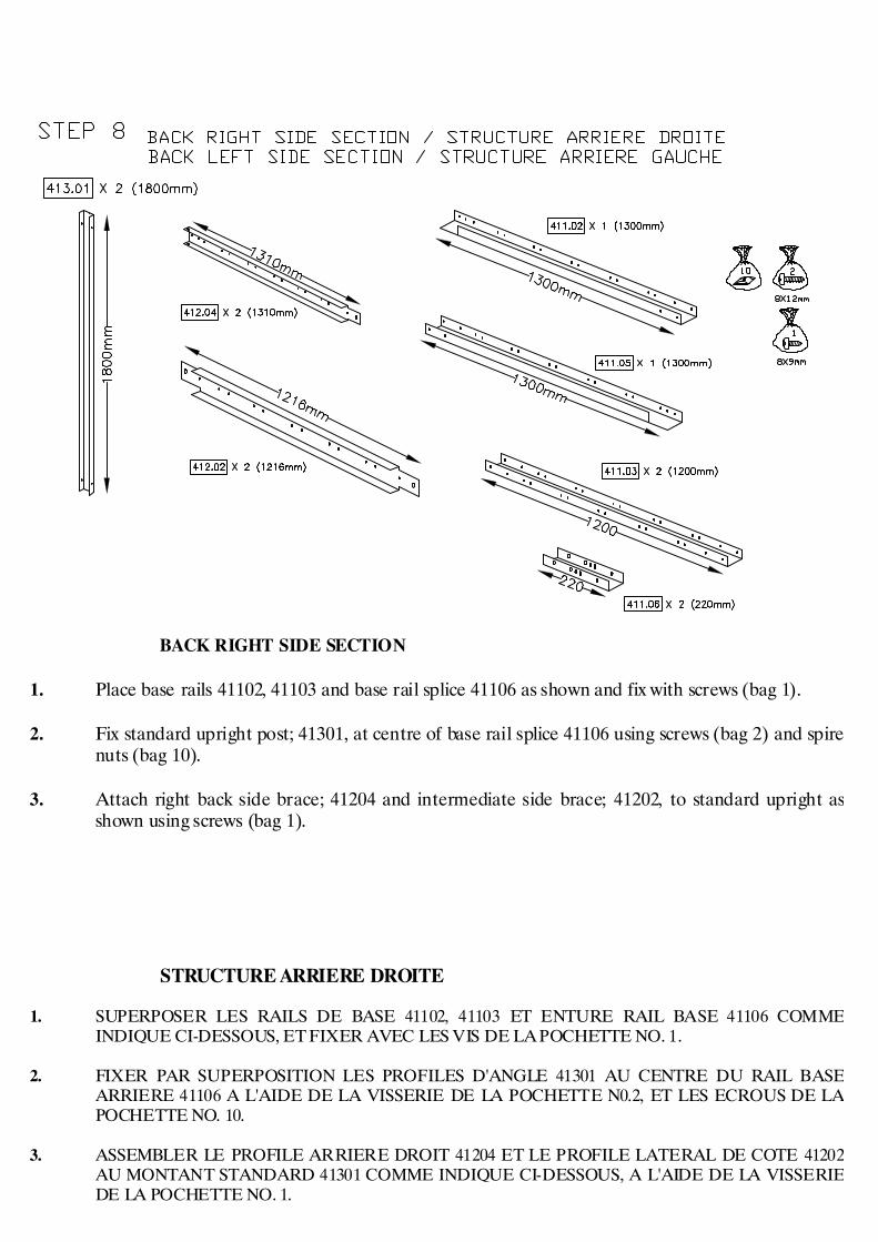
BACK RIGHT SIDE SECTION 1. Place base rails 41102, 41103 and base rail splice 41106 as shown and fix with screws (bag 1). 2. Fix standard upright post; 41301, at centre of base rail splice 41106 using screws (bag 2) and spire
nuts (bag 10). 3. Attach right back side brace; 41204 and intermediate side brace; 41202, to standard upright as
shown using screws (bag 1).
STRUCTURE ARRIERE DROITE 1. SUPERPOSER LES RAILS DE BASE 41102, 41103 ET ENTURE RAIL BASE 41106 COMME
INDIQUE CI-DESSOUS, ET FIXER AVEC LES VIS DE LA POCHETTE NO. 1. 2. FIXER PAR SUPERPOSITION LES PROFILES D'ANGLE 41301 AU CENTRE DU RAIL BASE
ARRIERE 41106 A L'AIDE DE LA VISSERIE DE LA POCHETTE N0.2, ET LES ECROUS DE LAPOCHETTE NO. 10.
3. ASSEMBLER LE PROFILE ARRIERE DROIT 41204 ET LE PROFILE LATERAL DE COTE 41202
AU MONTANT STANDARD 41301 COMME INDIQUE CI-DESSOUS, A L'AIDE DE LA VISSERIEDE LA POCHETTE NO. 1.


BACK RIGHT SIDE SECTION 4. Overlap sidebeams; 50119 and 50113 as shown using 4 screws (bag 1).
N.B. These may have to be removed later to facilitate fitting wall panels !!! 5. Fix spliced sidebeam to standard upright; 41301 as shown with screws (bag 1) and spire clips (bag
10), 1300mm from notched edge of 50119. 6. Fix 10318 corner panel to edge of back right section as shown using screws (bag1) and washers
(bag 12). 7. Fix three 10118 wall panels, starting at corner panel with screws (bag 1) and washers (bag 12).
REPEAT STEPS 1-7 FOR OPPOSITE SIDE (BACK LEFT) USING SIDE RHFRONT/LH REAR BASE RAIL 41105 INSTEAD OF 41102.
STRUCTURE ARRIERE DROITE 4. SUPEROSER ET VISSER LES POUTRE DU COTE 50113 ET 50119, A L'AIDE DE 4 VIS DE LA
POCHETTE NO.1.
NOTA: CES 4 VIS DEVRONT ETRE DEVISSEES PLUS TARD POUR FIXER LES PANNEAUXMURAUX.
5. FIXER LES POUTRES DE COTE AU MONTANT STANDARD 41301 COMME INDIQUE CI-
DESSOUS A 1300 MM DU FIL ENTAILLE, A L'AIDE DE LA VISSERIE DE LA POCHETTE NO.1ET LES EROUS DE LA POCHETTE NO.10.
6. FIXER LE PANNEAU D'ANGLE (103.18) AU PROFILE ARRIERE DROIT COMME INDIQUE CI-
DESSOUS, A L'AIDE DE LA VISSERIE DE LA POCHETTE NO.1 DES RONDELLES EN FIBRE DELA POCHETTE NO.12.
7. FIXER LES PANNEAUX MURAUX 10118 EN PARTANT DU PANNEAU D'ANGLE ET EN
UTILISANT LA VISSERIE DE LA POCHETTE NO.1 ET LES RONDELLES EN FIBRE DE LAPOCHETTE N0.12.
MEME MONTAGE DE 1 A 7 POUR LE COTE OPPOSE ARRIERE GAUCHE EN UTILISANT RAILBASE LATERAL AVANT DROIT / ARRIERE GAUCHE 41105 AU LIEU DE 41102.


FRONT RIGHT SIDE SECTION 1. Position base rails; 41105, 41103 and side base rail splice 41106 as shown and fix with screws (bag
1). 2. Fix standard upright to centre of base rail splice 41106 using screws (bag 2) and spire nuts (bag
10). 3. Fix front right side brace; 41203 and intermediate side brace; 41202, to centre hole in standard
upright 41301 using a screw (bag 1). 4. Fix sidebeam 50119 to standard upright 41301 (through hole 1300mm from front notched edge of
50119) using screws (bag 1) and spire clips (bag 10). 5. Fix three 10118 wall panels starting in position; 3rd hole from front of base rail. 3rd hole from front of side brace.
REPEAT STEPS FOR OPPOSITE SIDE (FRONT LEFT) USING SIDE LHFRONT /RH REAR BASE RAIL 41102 INSTEAD OF 41105.
STRUCTURE AVANT DROIT 1. POSITIONNER LES RAILS DE BASE 41105, 41103 ET ENTURE DU RAIL BASE LATERAL 41106
COMME INDIQUE CI-DESSOUS, ET FIXER AVEC LES VIS DE LA POCHETTE NO.1. ET LESRONDELLES DE LA POCHETTE NO.12.
2. FIXER LE MONTANT STANDARD 41301 AU CENTRE LES PROFILES D'ANGLE DE PILIER A
L'AIDE DE LA VISSERIE DE LA POCHETE NO.2, ET LES ECROUS DE LA POCHETTE NO.10. 3. ASSEMBLER LE PROFILE AVANT DROIT 41203 ET LE PROFILE LATERAL DE COTE 41202 AU
MONTANT STANARD 41301 COMME INDIQUE CI-DESSOUS, A L'AIDE DE LA VISSERIE DE LAPOCHETTE NO.1.
4. FIXER LA POUTRE DE COTE 50119 PAR LE TROU SPECIAL, AU MONTANT STANDARD DANS
LE TROU A 1300MM DU FIL ENTAILLE. 5. FIXER LES PANNEAUX MARAUX (101.18) COMME SUIT: - 4 EME TROU DE L'AVANT DU RAIL BASE, - 3 EME TROU DE L'AVANT DU CONTREVENTEMENT LATERALE.
IDEM POUR MONTAGE STRUCTURE OPPOSE GAUCHE EN UTILISANT RAIL BASE LATERALEAVANT GAUCHE/ ARRIERE DROIT 41102 AU LIEU DE 41105


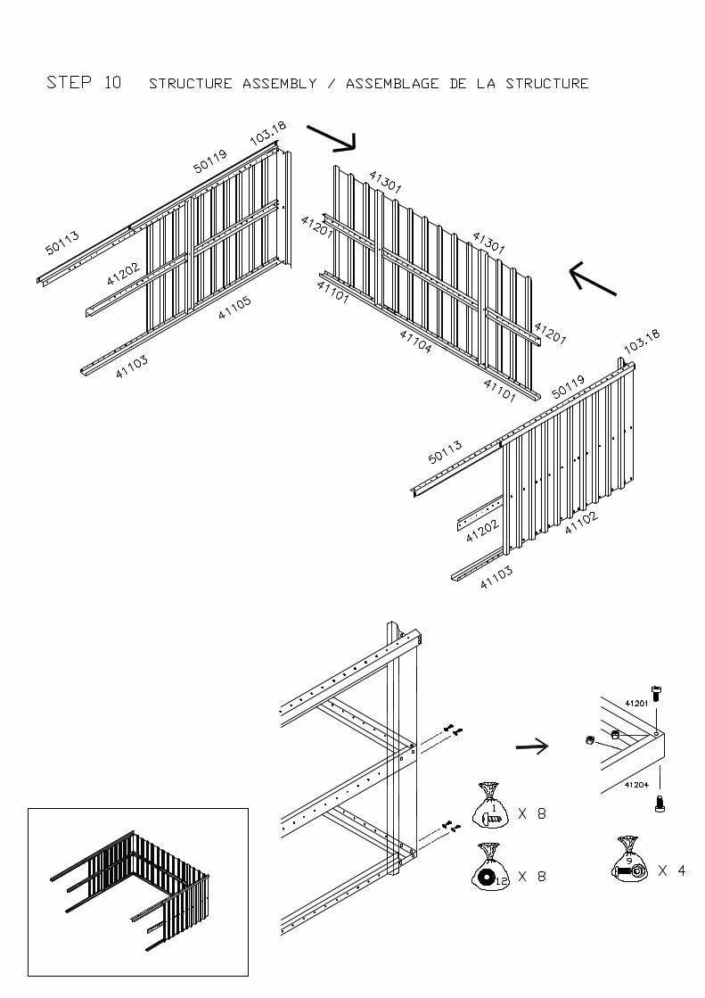
STRUCTURE ASSEMBLY 1. Raise back section and fix right back section at base rails with screws (bag 1). Secure side and
back braces with bolts and nuts (bag 9). 2. Raise back left side and fix to back section in same manner.
ALWAYS ENSURE SQUARENESS IN STRUCTURE ASSEMBLY. 3. Raise front right section and secure intermediate base rails; 41103's using base rail splice 41106.
Screw together sidebeams at top on two aligning holes (these screws may also need to beremoved to facilitate fixing roof panels).
4. Locate together; standard upright 41301 and two notched intermediate side braces 41202 at
center hole and fix. Attach two 10118 wall panels using screws (bag 1) and washers (bag 12).
REPEAT FOR FRONT LEFT SECTION.
ASSEMBLAGE DE LA STRUCTURE 1. DRESSER LA STRUCTURE ARRIERE ET LA FIXER AU PROFILE ARRIERE DROIT, AU RAIL
DE BASE (POCHETTE NO.1&NO.12) ET AU PROFILE LATERAL, AVEC DES BOULONS DE5MM DE LA POCHETTE N0.9.
2. DE LA MEME MANIERE, FIXER LE PROFILE ARRIERE GAUCHE AU RAIL DE BASE ET AU
PROFILE LATERAL.
S'ASSURER TOUJAIRS DE LA RECTITUDE DE LA STRUCTURE. 3. PRESENTER LA STRUCTURE DU COTE DROIT ET LA FIXER AU RAIL DE BASE DE COTE
41103 EN UTILISANT LES ENTURES RAIL BASE 41106. VISSER ENSEMBLE LES POUTRES DECOTE DANS LES DEUX TROUS (LES DEUX VIS DEVRONT ETRE DEVISSEES POURFACILITER LA FIXATION DES PANNEAUX DE TOIT).
4. ASSEMBLER LES MONTANTS STANDARD 41301, LES DEUX PROFILES LATERAUX
ENTAILLES DE COTE 41202 AU TROU CENTRAL ET FIXER. REPETER POUR LA STRUCTURE AVANT GAUCHE.
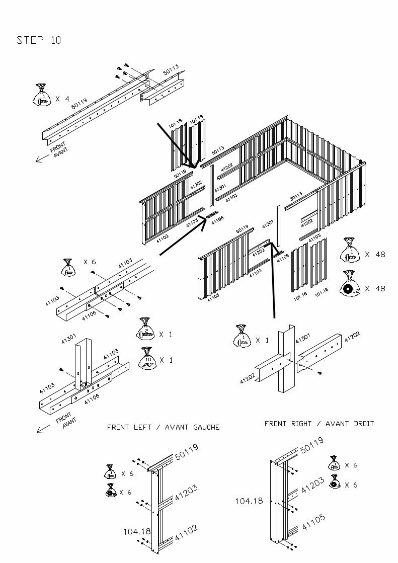

STRUCTURE ASSEMBLY 5. Fix front frame assembly to garage frame and corner panel with screws (bag 1) and washers (bag
12). 6. Fix roof truss sub-assemblies to all three opposite pairs of standard uprights. 7. Fix front frame angles, 41604 to front frame and corner panel attachment, using screws (bag 1)
and washers (bag 12) as shown.
ASSEMBLAGE DE LA STRUCTURE 5. ASSEMBLER LA STRUCTURE AVANT, LES PROFILES DE COTE DU GARAGE ET LES
PANNEAUX D'ANGLE, AVEC LA VISSERIE DE LA POCHETTE NO.1 ET LES RONDELLES DEPOCHETTE N0.12.
6. ASSEMBLER LA STRUCTURE DE TOIT SUR LES MONTANTS STANDARDS. 7. FIXER LES ANGLES DE LA STRUCTURE AVANT 41604 A LA STRUCTURE AVANT ET
L'ATTACHEMENT DU PANNEAU D'ANGLE, AVEC DES VIS (SAC 1) ET DES RONDELLES (SAC12) COMME INDIQUE.


ROOF FRAME ASSEMBLY 1. Fix left hand gable 301, right hand gable 302 and centre gable 305.3 to the wall panels at the back
of the garage with screws (bag 1) and washers (bag 12) use double spire clips (bag 13) on bottomedge of gables as needed (where 2 x 7mm holes occur) . Fix sidebeam 50119 to each gable endusing screws (bag 1) and washers (bag 12) (fig. 4).
2. Repeat for the front of the garage bag 13 not required. 3. Make available 3 sets of roof beams assembled earlier. 4. Fix one set of roof beams 502 to roof beam gussets 505 and 506 with bolts and nuts (bag 9). The
sloping sides of the roof beam should be fitted under the gable flanges (fig. 5). 5. Fit roof beams 502 to roof beam support 50630, gables 301/302 and centre gables 305.3 with bolts
and nuts (bag 9). 6. Fix roof beams to roof truss angles (roof truss angles fit between roof beams) with bolts and nuts
(bag 9).
ASSEMBLAGE DES PROFILES DE TOIT 1. FIXER LE PIGNON GAUCHE 301, LE PIGNON DROIT 302 ET LE PIGNON CENTRAL 305.3 AUX
PANNEAUX MURAUX ARRIERES DU GARAGE, A L'AIDE DE LA VISSERIE (POCHETTENO.1) ET DES RONDELLES DE LA POCHETTE NO.12. FIXER AUX EXTREMITES DESPOUTRES DE COTE 50119 (FIGURE 4).
2. MEME OPERATION DE MONTAGE POUR LE DEVANT DU GARAGE . 3. PREPARER LES TROIS POUTRES MONTEES PLUS TOT. 4. FIXER LES POUTRES FAITIERES 502 AUX EQUERRES DE POUTRE 505 ET 506 AVEC LA
VISSERIE DE LA POCHETTE N0.9. LES COTES INCLINES DE LA POUTRE DE TOIT DOIVENTETRE FIXES EN DESSOUS DES REBORDS DES PIGNONS (FIGURE 5).
5. ASSEMBLER LES POUTRES DE TOIT 502 AU SUPPORT DE TOIT 50360 ET AUX PIGNONS 301,
302 ET 305.3 A L'AIDE DES BOULONS ET ECROUS DE LA POCHETTE NO.9. LES COTESINCLINES DE LA POUTRE DE TOIT DOIVENT ETRE FIXES AU DESSUS DU REBORD DESPIGNONS 301 ET 302 ET EN DESSOUS DU REBORD DU PIGNON CENTRAL 305.3.
6. FIXER LES EQUERRES DE TOIT AUX POUTRES D'ANGLE RENFORCEES AVEC LES BOULONS DE LA POCHETTE NO. 9.


ROOF ASSEMBLY MOST IMPORTANT! BEFORE FITTING THE ROOF PANELS CHECK YOUR BUILDING FOR SQUARENESS BYENSURING THAT THE DIAGONALS ARE EQUAL. 1. Starting at the rear of the building fit roof panels 203.29 and 204.29 over gable flanges (panel
should overlap gable by 75mm) and fix with screws (bag 1) and washers (bag 14) to gables, roofbeams and sidebeams on each side of the building.
2. Fix ridge cover panel 50307 to roof panels using 12mm screws (bag 2) and washers (bag 14)
leaving end holes free to fit ridge cover cap 507. 3. Fit narrow roof panels, 202.3 followed by 205 translucent roof panels secure with screws (bag 1)
and washers (bag 14). WHERE RIDGE COVER PANELS OVERLAP, FIX USING SCREWS AND WASHERS (BAGS1&14).
4. When the previous four panels are fitted, fix ridge cover panel 50303 with screws and washers(bags 2&14).
5. Fit roof panels 201.3 followed by ridge cover 50302. Secure using screws and washers (bags 1,
2&14).
REPEAT OPERATION 5 FOR 5 MORE PANELS AND RIDGE COVERS EACH SIDE. 6. Fix roof panels 203.29 and 204.29 at front of garage to gable, roof beams and side beams using
screws (bag 1) and washers (bag 14). 7. Fix ridge cover panel, 50308 to front of garage (leave front holes free to ensure that ridge cover
cap 507 can be fitted). ASSEMBLAGE DU TOIT
TRES IMPORTANT AVANT D'ASSEMBLER LES PANNEAUX DU TOIT, VOUS ASSURER QUE LE GARAGE EST A L'EQUERRE ENCONTROLANT QUE LES PROFILES DIAGONAUX SOIENT DE LONGUEUR EGALE. 1. COMMENCER PAR L'ARRIERE DU GARAGE EN FIXANT LES PANNEAUX DE TOIT 203.29 AU
DESSUS DES REBORDS DE PIGNON, ET FIXER A L'AIDE DES VIS DE LA POCHETTE NO.1 ETDES RONDELLES DE LA POCHETTE NO. 14 LES PIGNONS, POUTRES FAITIERES ETPOUTRES DE COTE, SUR CHAQUE COTE DU GARAGE.
2. FIXER LE COUVRE FAITIERE 50307 SUR LES PANNEAUX DE TOIT EN UTILISANT LES VIS
DE 12MM DE LA POCHETTE NO. 2 ET LES RONDELLES DE LA POCHETTE NO. 14, ENLAISSANT LE DERNIER LIBRE PERMETTANT DE FIXER LES EMBOUTS DE FAITIERE 507.
3. FIXER LE PETIT PANNEAU DE TOIT 202.3 AVEC LES VIS DE LA POCHETTE NO. 1 ET LES
RONDELLES DE LA POCHETTE NO.14, PUIS LES PANNEAUX TRANSLUCIDES. UTILISER LAVISSERIE DE LA POCHETTE NO.1 POUR FIXER LES PANNEAUX SUPERPOSES.
4. LES 4 PANNEAUX PREVUS ETANT ASSEMBLES, FIXER LA COUVRE FAITIERE 50303 AVEC
LA VISSERIE DE LA POCHETTE NO.2 ET LES RONDELLES DE LA POCHETTE NO.14. 5. FIXER LES PANNEAUX DE TOIT 201.3 PUIS LE COUVRE FAITIERE 50302, AVEC LES VIS DE
LA POCHETTE NO. 1 ET LES RONDELLES DE LA POCHETTE NO. 14.
REPETER OPERATION 5 PANNEAUX ADDITIONELS ET COURESFAITIERES. 6. FIXER LES PANNEAUX DE TOIT 203.29 ET 204.29 AUX PIGNONS AVANT DU GARAGE,
POUTRE DE TOIT ET DE COTE, EN UTILISANT LA VISSERIE DE LA POCHETTE NO.14 ET LESRONDELLES DE LA POCHETTE NO.14.
7. FIXER LA COUVRE FAITIERE 50308 A L AVANT DU GARGAGE, EN LAISSANT LES TROUS LIBRES POUR FIXER L EMBOUT DE FAITIERE.


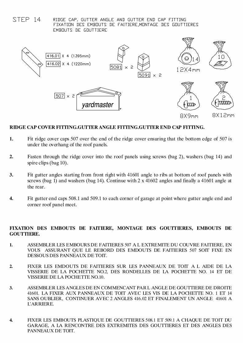
RIDGE CAP COVER FITTING.GUTTER ANGLE FITTING.GUTTER END CAP FITTING. 1. Fit ridge cover caps 507 over the end of the ridge cover ensuring that the bottom edge of 507 is
under the overhang of the roof panels. 2. Fasten through the ridge cover into the roof panels using screws (bag 2), washers (bag 14) and
spire clips (bag 10). 3. Fit gutter angles starting from front right with 41601 angle to ribs at bottom of roof panels with
screws (bag 1) and washers (bag 14). Continue with 2 x 41602 angles and finally a 41601 angle atthe rear.
4. Fit gutter end caps 508.1 and 509.1 to each corner of garage at point where gutter angle end and
corner roof panel meet. FIXATION DES EMBOUTS DE FAITIERE, MONTAGE DES GOUTTIERES, EMBOUTS DEGOUTTIERE. 1. ASSEMBLER LES EMBOURS DE FAITIERES 507 A L EXTREMITE DU COUVRE FAITIERE, EN
VOUS ASSURANT QUE LE REBORD DES EMDOUTS DE FAITIERES 507 SOIT FIXE ENDESSOUS DES PANNEAUX DE TOIT.
2. FIXER LES EMDOUTS DE FAITIERES SUR LES PANNEAUX DE TOIT A L AIDE DE LA
VISSERIE DE LA POCHETTE NO.2, DES RONDELLES DE LA POCHETTE NO. 14 ET DEVISSERIE DE LA POCHETTE NO.10.
3. ASSEMBLER LES ANGLES DE EN COMMENCANT PAR L ANGLE DE GOUTTIERE DE DROITE
41601. LA FIXER AUX PANNEAUX DE TOIT AVEC LES VIS DE LA POCHETTE NO. 1 ET 14SANS OUBLIER, CONTINUER AVEC 2 ANGLES 416.02 ET FINALEMENT UN ANGLE 41601 AL’ARRIERE.
4. FIXER LES EMBOUTS PLASTIQUE DE GOUTTIERES 508.1 ET 509.1 A CHAQUE DE TOIT DU
GARAGE, A LA RENCONTRE DES EXTREMITES DES GOUTTIERES ET DES ANGLES DESPANNEAUX DE TOIT.


ANCHORING GARAGE. 1. Anchor garage in the 13 positions shown with anchor kit provided (M8 x 50 coach screws plugs
and washers). Holes to locate are punched in the base rails. Positions: 2 in front frame, 4 along each side, 3 along rear
POSITION OF GARAGE MUST BE DETERMINED AT THIS POINT AND SQUARNESSMUST BE ENSURED.
2. When anchoring is complete, hang doors in position using the remainder of the countersunk
bolts, nuts and washers provided.
ANCRAGE DE L'ABRI 1. FIXER L'ABRI DANS LE 13 POSITIONS MONTRES AVEC LE KIT D'ANCRAGE PREVU. M8 X 50
VIS DE CARROSSIER, CHEVILLES ET RONDELLES. TROUS A LOCALISES SONT PERCESDANS LES RAILS BASES. POSITIONS: 2 DANS LA STRUCTURE AVANTE, 4 SUR CHAQUE COTE, 3 SUR L'ARRIERE.
IL FAUT DETERMINER LA POSITION DE LA GARAGE A CE MOMENT ET S'ASSURER DE LARECTITUDE.
2. APRES AVOIR FINI L'ANCRAGE, MONTER LES PORTES AVEC LE RESTE DES BOULONS
NOYES, ECROUS ET RONDELLES PREVUS.
