international iso/iec standard 11801 -...
TRANSCRIPT

INTERNATIONALSTANDARD
ISO/IEC11801
Second edition2002-09
Information technology –Generic cabling for customer premises
Reference numberISO/IEC 11801:2002(E)
COPYRIGHT 2004; International Organization for Standardization
Document provided by IHS Licensee=Avaya/5937902101, User=, 01/05/2004 01:59:27MST Questions or comments about this message: please call the Document PolicyGroup at 1-800-451-1584.
--``,,`,`````,,,`,,`,`,,````,-`-`,,`,,`,`,,`---

COPYRIGHT 2004; International Organization for Standardization
Document provided by IHS Licensee=Avaya/5937902101, User=, 01/05/2004 01:59:27MST Questions or comments about this message: please call the Document PolicyGroup at 1-800-451-1584.
--``,,`,`````,,,`,,`,`,,````,-`-`,,`,,`,`,,`---

INTERNATIONALSTANDARD
ISO/IEC11801
Second edition2002-09
Information technology –Generic cabling for customer premises
PRICE CODE
ISO/IEC 2002
All rights reserved. Unless otherwise specified, no part of this publication may be reproduced or utilized in any form or by anymeans, electronic or mechanical, including photocopying and microfilm, without permission in writing from the publisher.
ISO/IEC Copyright Office • Case postale 56 • CH-1211 Genève 20 • Switzerland
For price, see current catalogue
XB
COPYRIGHT 2004; International Organization for Standardization
Document provided by IHS Licensee=Avaya/5937902101, User=, 01/05/2004 01:59:27MST Questions or comments about this message: please call the Document PolicyGroup at 1-800-451-1584.
--``,,`,`````,,,`,,`,`,,````,-`-`,,`,,`,`,,`---

– 2 – 11801 © ISO/IEC:2002(E)
CONTENTS
FOREWORD .........................................................................................................................10INTRODUCTION ...................................................................................................................111 Scope .............................................................................................................................132 Normative references......................................................................................................133 Definitions, abbreviations and symbols ...........................................................................17
3.1 Definitions .............................................................................................................173.2 Abbreviations.........................................................................................................233.3 Symbols ................................................................................................................24
3.3.1 Variables ...................................................................................................243.3.2 Indices .......................................................................................................25
4 Conformance ..................................................................................................................255 Structure of the generic cabling system ..........................................................................26
5.1 General .................................................................................................................265.2 Functional elements...............................................................................................265.3 Cabling subsystems...............................................................................................27
5.3.1 General......................................................................................................275.3.2 Campus backbone cabling subsystem........................................................275.3.3 Building backbone cabling subsystem ........................................................285.3.4 Horizontal cabling subsystem.....................................................................285.3.5 Design objectives.......................................................................................28
5.4 Interconnection of subsystems...............................................................................295.4.1 General......................................................................................................295.4.2 Centralised cabling architecture .................................................................30
5.5 Accommodation of functional elements ..................................................................305.6 Interfaces ..............................................................................................................30
5.6.1 Equipment interfaces and test interfaces....................................................305.6.2 Channel and permanent link ......................................................................325.6.3 External network interface..........................................................................32
5.7 Dimensioning and configuring ................................................................................325.7.1 Distributors ................................................................................................325.7.2 Cables .......................................................................................................345.7.3 Work area cords and equipment cords .......................................................345.7.4 Patch cords and jumpers ...........................................................................345.7.5 Telecommunications outlet (TO) ................................................................355.7.6 Consolidation point ....................................................................................365.7.7 Telecommunications rooms and equipment rooms .....................................365.7.8 Building entrance facilities .........................................................................365.7.9 External services cabling ...........................................................................36
6 Performance of balanced cabling ....................................................................................376.1 General .................................................................................................................376.2 Layout ...................................................................................................................386.3 Classification of balanced cabling ..........................................................................396.4 Balanced cabling performance...............................................................................39
6.4.1 General......................................................................................................39
COPYRIGHT 2004; International Organization for Standardization
Document provided by IHS Licensee=Avaya/5937902101, User=, 01/05/2004 01:59:27MST Questions or comments about this message: please call the Document PolicyGroup at 1-800-451-1584.
--``,,`,`````,,,`,,`,`,,````,-`-`,,`,,`,`,,`---

11801 © ISO/IEC:2002(E) – 3 –
6.4.2 Return loss ................................................................................................396.4.3 Insertion loss/attenuation ...........................................................................406.4.4 NEXT .........................................................................................................416.4.5 Attenuation to crosstalk ratio (ACR) ...........................................................446.4.6 ELFEXT .....................................................................................................456.4.7 Direct current (d.c.) loop resistance ...........................................................476.4.8 Direct current (d.c.) resistance unbalance ..................................................486.4.9 Current carrying capacity ...........................................................................486.4.10 Operating voltage ......................................................................................486.4.11 Power capacity ..........................................................................................486.4.12 Propagation delay ......................................................................................486.4.13 Delay skew ................................................................................................496.4.14 Unbalance attenuation ...............................................................................496.4.15 Coupling attenuation ..................................................................................50
7 Reference implementations for balanced cabling ............................................................507.1 General .................................................................................................................507.2 Balanced cabling ...................................................................................................50
7.2.1 General......................................................................................................507.2.2 Horizontal cabling ......................................................................................507.2.3 Backbone cabling.......................................................................................54
8 Performance of optical fibre cabling ................................................................................558.1 General .................................................................................................................558.2 Component choice .................................................................................................558.3 Channel attenuation...............................................................................................568.4 Channel topology...................................................................................................568.5 Propagation delay..................................................................................................58
9 Cable requirements.........................................................................................................589.1 General .................................................................................................................589.2 Balanced cables ....................................................................................................58
9.2.1 Basic performance requirements................................................................589.2.2 Additional requirements .............................................................................599.2.3 Additional performance requirements for flexible cables.............................60
9.3 Additional crosstalk considerations for cable sharing in balanced cables ...............609.3.1 General......................................................................................................609.3.2 Power summation in backbone cables........................................................609.3.3 Hybrid, multi-unit and cables connected to more than one TO....................60
9.4 Optical fibre cables ................................................................................................619.4.1 Optical fibre types ......................................................................................619.4.2 Generic performance requirements ............................................................619.4.3 Multimode optical fibre cable......................................................................619.4.4 Single-mode optical fibre cables ................................................................62
10 Connecting hardware requirements.................................................................................6210.1 General requirements ............................................................................................62
10.1.1 Applicability ...............................................................................................6210.1.2 Location.....................................................................................................6310.1.3 Design .......................................................................................................6310.1.4 Operating environment...............................................................................6310.1.5 Mounting....................................................................................................63
COPYRIGHT 2004; International Organization for Standardization
Document provided by IHS Licensee=Avaya/5937902101, User=, 01/05/2004 01:59:27MST Questions or comments about this message: please call the Document PolicyGroup at 1-800-451-1584.
--``,,`,`````,,,`,,`,`,,````,-`-`,,`,,`,`,,`---

– 4 – 11801 © ISO/IEC:2002(E)
10.1.6 Installation practices ..................................................................................6310.1.7 Marking and colour coding .........................................................................64
10.2 Connecting hardware for balanced cabling ............................................................6410.2.1 General requirements ................................................................................6410.2.2 Performance marking .................................................................................6410.2.3 Mechanical characteristics .........................................................................6410.2.4 Electrical characteristics ............................................................................6610.2.5 Telecommunications outlet requirements ...................................................7210.2.6 Design considerations for installation .........................................................73
10.3 Optical fibre connecting hardware..........................................................................7410.3.1 General requirements ................................................................................7410.3.2 Marking and colour coding .........................................................................7410.3.3 Mechanical and optical characteristics .......................................................7410.3.4 Telecommunications outlet requirements ...................................................7510.3.5 Connection schemes for optical fibre cabling .............................................75
11 Screening practices ........................................................................................................7711.1 General .................................................................................................................7711.2 Electromagnetic performance ................................................................................7711.3 Earthing.................................................................................................................78
12 Administration.................................................................................................................7813 Balanced cords ...............................................................................................................78
13.1 Introduction ...........................................................................................................7813.2 Insertion loss .........................................................................................................7813.3 Return loss ............................................................................................................7913.4 NEXT.....................................................................................................................79
Annex A (normative) Balanced permanent link and CP link performance ..............................82A.1 General ..........................................................................................................................82A.2 Performance ...................................................................................................................82
A.2.1 General......................................................................................................82A.2.2 Return loss ................................................................................................83A.2.3 Insertion loss/attenuation ...........................................................................84A.2.4 NEXT .........................................................................................................85A.2.5 Attenuation to crosstalk ratio (ACR) ...........................................................88A.2.6 ELFEXT .....................................................................................................89A.2.7 Direct current (d.c.) loop resistance ...........................................................92A.2.8 Direct current (d.c.) resistance unbalance ..................................................93A.2.9 Propagation delay ......................................................................................93A.2.10 Delay skew ................................................................................................94
Annex B (normative) Test procedures ..................................................................................96B.1 General ..........................................................................................................................96B.2 Channel and link performance testing .............................................................................96
B.2.1 Testing balanced cabling channels, permanent links and CP links .............96B.2.2 Testing optical fibre cabling channels ........................................................96B.2.3 Channel and link test schedules.................................................................96
B.3 Transmission testing of cords for balanced cabling .........................................................97B.4 Transmission testing of components for cabling ..............................................................98
B.4.1 Transmission testing of copper cables for balanced cabling .......................98
COPYRIGHT 2004; International Organization for Standardization
Document provided by IHS Licensee=Avaya/5937902101, User=, 01/05/2004 01:59:27MST Questions or comments about this message: please call the Document PolicyGroup at 1-800-451-1584.
--``,,`,`````,,,`,,`,`,,````,-`-`,,`,,`,`,,`---

11801 © ISO/IEC:2002(E) – 5 –
B.4.2 Transmission testing of connecting hardware for balanced cabling ............98B.4.3 Transmission testing of cables for optical cabling.......................................98B.4.4 Transmission testing of connectors for optical cabling................................98
Annex C (normative) Mechanical and environmental performance testing ofconnecting hardware for balanced cabling ......................................................................99
C.1 Introduction.....................................................................................................................99C.2 Test requirements ...........................................................................................................99
C.2.1 General......................................................................................................99C.2.2 Initial test measurements ...........................................................................99C.2.3 Environmental and mechanical performance ............................................100
Annex D (informative) Electromagnetic characteristics ......................................................104Annex E (informative) Acronyms for balanced cables ........................................................105Annex F (informative) Supported applications ....................................................................107F.1 Supported applications for balanced cabling .................................................................107F.2 Supported applications for optical fibre cabling .............................................................109Annex G (informative) Channel and permanent link models for balanced cabling ...............113G.1 General ........................................................................................................................113G.2 Insertion loss ................................................................................................................113
G.2.1 Insertion loss of the channel configuration ...............................................113G.2.2 Insertion loss of the permanent link configurations ...................................114G.2.3 Assumptions for insertion loss .................................................................114
G.3 NEXT............................................................................................................................115G.3.1 NEXT of the channel configuration ...........................................................115G.3.2 NEXT of the permanent link configurations ..............................................115G.3.3 Assumptions for NEXT .............................................................................116
G.4 ELFEXT ........................................................................................................................119G.4.1 ELFEXT of the channel configuration .......................................................119G.4.2 ELFEXT for the permanent link configurations .........................................119G.4.3 Assumptions for ELFEXT .........................................................................120
G.5 Return loss ...................................................................................................................120G.5.1 Return loss of the channel and permanent link configurations ..................120G.5.2 Assumptions for the return loss circuit analysis method ...........................121
Annex H (informative) Class F channel and permanent link with two connections ...............124Annex I (informative) Significant changes to balanced cabling requirements with
respect to earlier editions of this International Standard................................................125I.1 General ........................................................................................................................125I.2 References ...................................................................................................................125I.3 Structural elements .......................................................................................................125I.4 Product designation ......................................................................................................125I.5 Component requirements ..............................................................................................125I.6 Installed cabling requirements ......................................................................................126Bibliography ........................................................................................................................132
COPYRIGHT 2004; International Organization for Standardization
Document provided by IHS Licensee=Avaya/5937902101, User=, 01/05/2004 01:59:27MST Questions or comments about this message: please call the Document PolicyGroup at 1-800-451-1584.
--``,,`,`````,,,`,,`,`,,````,-`-`,,`,,`,`,,`---

– 6 – 11801 © ISO/IEC:2002(E)
Figure 1 – Structure of generic cabling ..................................................................................27Figure 2 – Hierarchical structure of generic cabling ...............................................................29Figure 3 – Structures for centralised generic cabling .............................................................29Figure 4 – Accommodation of functional elements .................................................................30Figure 5 – Interconnect models .............................................................................................31Figure 6 – Cross-connect models ..........................................................................................31Figure 7 – Equipment and test interfaces ..............................................................................31Figure 8 – Example of a generic cabling system with combined BD and FD...........................33Figure 9 – Inter-relationship of functional elements in an installation with redundancy...........34Figure 10 – Channel, permanent link and CP link of a balanced cabling ................................37Figure 11 – Example of a system showing the location of cabling interfacesand extent of associated channels ........................................................................................38Figure 12 – Horizontal cabling models...................................................................................52Figure 13 – Backbone cabling model .....................................................................................54Figure 14 – Combined backbone/horizontal channels ............................................................57Figure 15 – Eight-position outlet pin and pair grouping assignments (front viewof connector) .........................................................................................................................73Figure 16 – Duplex SC connectivity configuration..................................................................76Figure 17 – Optical fibre patch cord ......................................................................................77Figure A.1 – Link options ......................................................................................................82Figure E.1 – Cable naming schema......................................................................................105Figure E.2 – Cable types .....................................................................................................106Figure G.1 – Example of computation of NEXT with higher precision...................................116Figure H.1 – Two connection channel and permanent link ...................................................124Figure I.1 – Horizontal cabling model ..................................................................................127Figure I.2 – Backbone cabling model...................................................................................127
COPYRIGHT 2004; International Organization for Standardization
Document provided by IHS Licensee=Avaya/5937902101, User=, 01/05/2004 01:59:27MST Questions or comments about this message: please call the Document PolicyGroup at 1-800-451-1584.
--``,,`,`````,,,`,,`,`,,````,-`-`,,`,,`,`,,`---

11801 © ISO/IEC:2002(E) – 7 –
Table 1 – Maximum channel lengths .....................................................................................32Table 2 – Return loss for channel..........................................................................................40Table 3 – Informative return loss values for channel at key frequencies ................................40Table 4 – Insertion loss for channel.......................................................................................41Table 5 – Informative insertion loss values for channel at key frequencies ............................41Table 6 – NEXT for channel ..................................................................................................42Table 7 – Informative NEXT values for channel at key frequencies........................................42Table 8 – PS NEXT for channel.............................................................................................43Table 9 – Informative PS NEXT values for channel at key frequencies ..................................43Table 10 – Informative ACR values for channel at key frequencies........................................44Table 11 – Informative PS ACR values for channel at key frequencies ..................................45Table 12 – ELFEXT for channel.............................................................................................46Table 13 – Informative ELFEXT values for channel at key frequencies ..................................46Table 14 – PS ELFEXT for channel .......................................................................................47Table 15 – Informative PS ELFEXT values for channel at key frequencies ............................47Table 16 – Direct current (d.c.) loop resistance for channel ...................................................47Table 17 – Propagation delay for channel .............................................................................48Table 18 – Informative propagation delay values for channel at key frequencies ...................49Table 19 – Delay skew for channel........................................................................................49Table 20 – Unbalance attenuation for channel.......................................................................50Table 21 – Horizontal link length equations ...........................................................................53Table 22 – Backbone link length equations ...........................................................................55Table 23 – Channel attenuation.............................................................................................56Table 24 – Basic requirements of balanced cables ................................................................58Table 25 – Mechanical characteristics of balanced cables.....................................................59Table 26 – Optical fibre cable attenuation .............................................................................61Table 27 – Multimode optical fibre modal bandwidth..............................................................62Table 28 – Mechanical characteristics of connecting hardware for use withbalanced cabling ...................................................................................................................65Table 29 – Electrical characteristics of telecommunications outlets intendedfor use with balanced cabling ................................................................................................67Table 30 – Return loss ..........................................................................................................68Table 31 – Insertion loss .......................................................................................................68Table 32 – Near end crosstalk (NEXT) ..................................................................................68Table 33 – Power sum near end crosstalk (PS NEXT) ...........................................................69Table 34 – Far end crosstalk (FEXT) .....................................................................................69Table 35 – Power sum far end crosstalk (PS FEXT ...............................................................70Table 36 – Input to output resistance ....................................................................................70Table 37 – Input to output resistance unbalance ...................................................................70Table 38 – Current carrying capacity .....................................................................................71Table 39 – Propagation delay................................................................................................71Table 40 – Delay skew ..........................................................................................................71
COPYRIGHT 2004; International Organization for Standardization
Document provided by IHS Licensee=Avaya/5937902101, User=, 01/05/2004 01:59:27MST Questions or comments about this message: please call the Document PolicyGroup at 1-800-451-1584.
--``,,`,`````,,,`,,`,`,,````,-`-`,,`,,`,`,,`---

– 8 – 11801 © ISO/IEC:2002(E)
Table 41 – Transverse conversion loss (TCL) f.f.s.................................................................71Table 42 – Transfer impedance (screened connectors only) ..................................................72Table 43 – Insulation resistance............................................................................................72Table 44 – Voltage proof .......................................................................................................72Table 45 – Matrix of backward compatible mated modular connector performance ................73Table 46 – Mechanical and optical characteristics of optical fibre connecting hardware.........75Table 47 – Minimum return loss for balanced cords...............................................................79Table 48 – Informative values of return loss at key frequencies for Category 5, 6and 7 cords ...........................................................................................................................79Table 49 – Informative values of NEXT at key frequencies for Category 5, 6and 7 cords ...........................................................................................................................81Table A.1 – Return loss for permanent link or CP link............................................................83Table A.2 – Informative return loss values for permanent link with maximumimplementation at key frequencies ........................................................................................83Table A.3 – Insertion loss for permanent link or CP link ........................................................84Table A.4 – Informative insertion loss values for permanent link with maximumimplementation at key frequencies ........................................................................................85Table A.5 – NEXT for permanent link or CP link ....................................................................86Table A.6 – Informative NEXT values for permanent link with maximum implementationat key frequencies .................................................................................................................86Table A.7 – PS NEXT for permanent link or CP link...............................................................87Table A.8 – Informative PS NEXT values for permanent link with maximumimplementation at key frequencies ........................................................................................88Table A.9 – Informative ACR values for permanent link with maximum implementationat key frequencies .................................................................................................................89Table A.10 – Informative PS ACR values for permanent link with maximumimplementation at key frequencies ........................................................................................89Table A.11 – ELFEXT for permanent link or CP link ..............................................................90Table A.12 – Informative ELFEXT values for permanent link with maximumimplementation at key frequencies ........................................................................................91Table A.13 – PS ELFEXT for permanent link or CP link .........................................................92Table A.14 – Informative PS ELFEXT values for permanent link with maximumimplementation at key frequencies ........................................................................................92Table A.15 – Direct current (d.c.) loop resistance for permanent link or CP link.....................93Table A.16 – Informative d.c. loop resistance for permanent link with maximumimplementation......................................................................................................................93Table A.17 – Propagation delay for permanent link or CP link ...............................................94Table A.18 – Informative propagation delay values for permanent link with maximumimplementation at key frequencies ........................................................................................94Table A.19 – Delay skew for permanent link or CP link..........................................................95Table A.20 – Informative delay skew for permanent link with maximum implementation ........95Table B.1 – Cabling characteristics of copper and optical fibre cabling for acceptance,compliance and reference testing ..........................................................................................97Table C.1 – Group P ...........................................................................................................100Table C.2 – Group A ...........................................................................................................101Table C.3 – Group B ...........................................................................................................102Table C.4 – Group C ...........................................................................................................103
COPYRIGHT 2004; International Organization for Standardization
Document provided by IHS Licensee=Avaya/5937902101, User=, 01/05/2004 01:59:27MST Questions or comments about this message: please call the Document PolicyGroup at 1-800-451-1584.
--``,,`,`````,,,`,,`,`,,````,-`-`,,`,,`,`,,`---

11801 © ISO/IEC:2002(E) – 9 –
Table C.5 – Group D ...........................................................................................................103Table F.1 – Applications using balanced cabling .................................................................108Table F.2 – Modular connector pin assignment for applications...........................................109Table F.3 – Supported applications using optical fibre cabling.............................................110Table F.4 – Maximum channel lengths supported by optical fibre applications formultimode fibre ...................................................................................................................111Table F.5 – Maximum channel length supported by optical fibre applications for single-mode fibres .........................................................................................................................112Table G.1 – Insertion loss deviation. ...................................................................................114Table H.1 – ACR and PS ACR values for 2 connection class F channels andpermanent links at key frequencies .....................................................................................124
Table I.1 – Principal transmission performance requirements of 150 Ω connectinghardware.............................................................................................................................126Table I.2 – Minimum return loss limits for links, permanent links and channels for thedifferent cabling classes......................................................................................................128Table I.3 – Maximum attenuation limits for links, permanent links and channels for thedifferent cabling classes......................................................................................................128Table I.4 – Minimum NEXT limits for links, permanent links and channels for thedifferent cabling classes......................................................................................................129Table I.5 – Minimum ACR limits for links, permanent links and channels for thedifferent cabling classes......................................................................................................129Table I.6 – Maximum propagation delay limits for links, permanent links and channelsfor the different cabling classes...........................................................................................130Table I.7 – Maximum d.c. loop resistance limits for links, permanent links and channelsfor the different cabling classes...........................................................................................130Table I.8 – Minimum unbalance attenuation (LCL/LCTL) limits for links, permanentlinks and channels for the different cabling classes .............................................................130Table I.9 – Minimum PS NEXT, PS ACR, ELFEXT and PS ELFEXT limits forpermanent links and channels for the different cabling classes............................................131Table I.10 – Maximum delay skew limits for permanent links and channels for thedifferent cabling classes......................................................................................................131
COPYRIGHT 2004; International Organization for Standardization
Document provided by IHS Licensee=Avaya/5937902101, User=, 01/05/2004 01:59:27MST Questions or comments about this message: please call the Document PolicyGroup at 1-800-451-1584.
--``,,`,`````,,,`,,`,`,,````,-`-`,,`,,`,`,,`---

– 10 – 11801 © ISO/IEC:2002(E)
INFORMATION TECHNOLOGY –GENERIC CABLING FOR CUSTOMER PREMISES
FOREWORD1) ISO (International Organization for Standardization) and IEC (International Electrotechnical Commission) form the
specialized system for worldwide standardization. National bodies that are members of ISO or IEC participate inthe development of International Standards through technical committees established by the respectiveorganization to deal with particular fields of technical activity. ISO and IEC technical committees collaborate infields of mutual interest. Other international organizations, governmental and non-governmental, in liaison withISO and IEC, also take part in the work.
2) In the field of information technology, ISO and IEC have established a joint technical committee, ISO/IEC JTC 1.Draft International Standards adopted by the joint technical committee are circulated to national bodies for voting.Publication as an International Standard requires approval by at least 75 % of the national bodies casting a vote.
3) Attention is drawn to the possibility that some of the elements of this International Standard may be the subject ofpatent rights. ISO and IEC shall not be held responsible for identifying any or all such patent rights.
International Standard ISO/IEC 11801 was prepared by subcommittee 25: Interconnection ofinformation technology equipment, of ISO/IEC joint technical committee 1: Informationtechnology.
This second edition cancels and replaces the first edition published in 1995 and itsamendments 1 (1999) and 2 (1999) and constitutes a technical revision. The significantchanges with respect to the first edition and its amendments are listed in Annex I.
This publication has been drafted in accordance with the ISO/IEC Directives, Part 2.
This International Standard has taken into account requirements specified in applicationstandards listed in Annex F. It refers to International Standards for components and testmethods whenever appropriate International Standards are available.
COPYRIGHT 2004; International Organization for Standardization
Document provided by IHS Licensee=Avaya/5937902101, User=, 01/05/2004 01:59:27MST Questions or comments about this message: please call the Document PolicyGroup at 1-800-451-1584.
--``,,`,`````,,,`,,`,`,,````,-`-`,,`,,`,`,,`---

11801 © ISO/IEC:2002(E) – 11 –
INTRODUCTION
Within customer premises, the importance of the cabling infrastructure is similar to that ofother fundamental building utilities such as heating, lighting and mains power. As with otherutilities, interruptions to service can have a serious impact. Poor quality of service due to lackof design foresight, use of inappropriate components, incorrect installation, pooradministration or inadequate support can threaten an organisation's effectiveness.
Historically, the cabling within premises comprised both application specific and multipurposenetworks. The original edition of this standard enabled a controlled migration to genericcabling and the reduction in the use of application-specific cabling.
The subsequent growth of generic cabling designed in accordance with ISO/IEC 11801 has
a) contributed to the economy and growth of Information and Communications Technology(ICT),
b) supported the development of high data rate applications based upon a defined cablingmodel, and
c) initiated development of cabling with a performance surpassing the performance classesspecified in ISO/IEC 11801:1995 and ISO/IEC 11801 Ed1.2:2000.
NOTE ISO/IEC 11801, edition 1.2 consists of edition 1.0 (1995) and its amendments 1 (1999) and 2 (1999).
This second edition of ISO/IEC 11801 has been developed to reflect these increaseddemands and opportunities.
This International Standard provides:
a) users with an application independent generic cabling system capable of supporting awide range of applications;
b) users with a flexible cabling scheme such that modifications are both easy andeconomical;
c) building professionals (for example, architects) with guidance allowing the accommodationof cabling before specific requirements are known; that is, in the initial planning either forconstruction or refurbishment;
d) industry and applications standardization bodies with a cabling system which supportscurrent products and provides a basis for future product development.
This International Standard specifies a multi-vendor cabling system which may beimplemented with material from single and multiple sources, and is related to:
a) international standards for cabling components developed by committees of the IEC, forexample copper cables and connectors as well as optical fibre cables and connectors (seeClause 2 and bibliography);
b) standards for the installation and operation of information technology cabling as well as forthe testing of installed cabling (see Clause 2 and bibliography);
c) applications developed by technical committees of the IEC, by subcommittees ofISO/IEC JTC 1 and by study groups of ITU-T, for example for LANs and ISDN;
d) planning and installation guides which take into account the needs of specific applicationsfor the configuration and the use of cabling systems on customer premises(ISO/IEC 14709series).
Physical layer requirements for the applications listed in Annex F have been analysed todetermine their compatibility with cabling classes specified in this standard. These applicationrequirements, together with statistics concerning the topology of premises and the modeldescribed in 7.2, have been used to develop the requirements for Classes A to D and theoptical class cabling systems. New Classes E and F have been developed in anticipation offuture network technologies.
COPYRIGHT 2004; International Organization for Standardization
Document provided by IHS Licensee=Avaya/5937902101, User=, 01/05/2004 01:59:27MST Questions or comments about this message: please call the Document PolicyGroup at 1-800-451-1584.
--``,,`,`````,,,`,,`,`,,````,-`-`,,`,,`,`,,`---

– 12 – 11801 © ISO/IEC:2002(E)
As a result, generic cabling defined within this International Standard
a) specifies a cabling structure supporting a wide variety of applications,b) specifies channel and link Classes A, B, C, D and E meeting the requirements of
standardised applications,c) specifies channel and link Classes E and F based on higher performance components to
support the development and implementation of future applications,d) specifies optical channel and link Classes OF-300, OF-500, and OF-2000 meeting the
requirements of standardised applications and exploiting component capabilities to easethe implementation of applications developed in the future,
e) invokes component requirements and specifies cabling implementations that ensureperformance of permanent links and of channels that meet or exceed the requirements forcabling classes,
f) is targeted at, but not limited to, the general office environment.
This International Standard specifies a generic cabling system that is anticipated to have ausable life in excess of 10 years.
COPYRIGHT 2004; International Organization for Standardization
Document provided by IHS Licensee=Avaya/5937902101, User=, 01/05/2004 01:59:27MST Questions or comments about this message: please call the Document PolicyGroup at 1-800-451-1584.
--``,,`,`````,,,`,,`,`,,````,-`-`,,`,,`,`,,`---

11801 © ISO/IEC:2002(E) – 13 –
INFORMATION TECHNOLOGY –GENERIC CABLING FOR CUSTOMER PREMISES
1 Scope
ISO/IEC 11801 specifies generic cabling for use within premises, which may comprise singleor multiple buildings on a campus. It covers balanced cabling and optical fibre cabling.
ISO/IEC 11801 is optimised for premises in which the maximum distance over whichtelecommunications services can be distributed is 2 000 m. The principles of this InternationalStandard may be applied to larger installations.
Cabling defined by this standard supports a wide range of services, including voice, data,text, image and video.
This International Standard specifies directly or via reference the:
a) structure and minimum configuration for generic cabling,b) interfaces at the telecommunications outlet (TO),c) performance requirements for individual cabling links and channels,d) implementation requirements and options,e) performance requirements for cabling components required for the maximum distances
specified in this standard,f) conformance requirements and verification procedures.
Safety (electrical safety and protection, fire, etc.) and Electromagnetic Compatibility (EMC)requirements are outside the scope of this International Standard, and are covered by otherstandards and by regulations. However, information given by this standard may be ofassistance.
ISO/IEC 11801 has taken into account requirements specified in application standards listedin Annex F. It refers to available International Standards for components and test methodswhere appropriate.
2 Normative references
The following referenced documents are indispensable for the application of this document.For dated references, only the edition cited applies. For undated references, the latest editionof the referenced document (including any amendments) applies.
IEC 60027 (all parts), Letter symbols to be used in electrical technology
IEC 60068-1, Environmental testing – Part 1: General and guidance
IEC 60068-2-14, Environmental testing – Part 2: Tests – Test N: Change of temperature
IEC 60068-2-38, Environmental testing – Part 2: Tests – Test Z/AD: Compositetemperature/humidity cyclic test
IEC 60352-3, Solderless connections – Part 3: Solderless accessible insulation displacementconnections – General requirements, test methods and practical guidance
COPYRIGHT 2004; International Organization for Standardization
Document provided by IHS Licensee=Avaya/5937902101, User=, 01/05/2004 01:59:27MST Questions or comments about this message: please call the Document PolicyGroup at 1-800-451-1584.
--``,,`,`````,,,`,,`,`,,````,-`-`,,`,,`,`,,`---

– 14 – 11801 © ISO/IEC:2002(E)
IEC 60352-4, Solderless connections – Part 4: Solderless non-accessible insulationdisplacement connections – General requirements, test methods and practical guidance
IEC 60352-6, Solderless connections – Part 6: Insulation piercing connections – Generalrequirements, test methods and practical guidance
IEC 60364-1, Electrical installations of buildings – Part 1: Fundamental principles,assessment of general characteristics, definitions
IEC 60512-2:1985, Electromechanical components for electronic equipment; basic testingprocedures and measuring methods – Part 2: General examination, electrical continuity andcontact resistance tests, insulation tests and voltage stress testsAmendment 1 (1994)
IEC 60512-25-1, Connectors for electronic equipment – Tests and measurements – Part 25-1:Test 25a – Crosstalk ratio
IEC 60512-25-2:2002, Connectors for electronic equipment – Tests and measurements –Part 25-2: Test 25b – Attenuation (insertion loss)
IEC 60512-25-4:2001, Connectors for electronic equipment – Tests and measurements –Part 25-4: Test 25d – Propagation delay
IEC 60512-25-5, – Connectors for electronic equipment – Basic tests and measurements –Part 25-5: Test 25e – Return loss1
IEC 60603-7:1996, Connectors for frequencies below 3 MHz for use with printed boards –Part 7: Detail specification for connectors, 8-way, including fixed and free connectors withcommon mating features, with assessed quality
IEC 60603-7-1:2002, Connectors for electronic equipment – Part 7-1: Detail specification for8-way, shielded free and fixed connectors, with common mating features, with assessedquality
IEC 60603-7-7:2002, Connectors for electronic equipment – Part 7-7: Detail specification for8-way, shielded, free and fixed connectors, for data transmission with frequencies up to600 MHz (category 7, shielded)
IEC 60793-1-40, Optical fibres – Part 1-40: Measurement methods and test procedures –Attenuation
IEC 60793-1-41, Optical fibres – Part 1-41: Measurement methods and test procedures –Bandwidth
IEC 60793-1-44, Optical fibres – Part 1-44: Measurement methods and test procedures – Cut-off wavelength
IEC/PAS 60793-1-49:2002, Optical fibres – Part 1-49: Measurement methods and testprocedures – Differential mode delay
IEC 60793-2 (all parts), Optical fibres – Part 2: Product specifications
IEC 60793-2-10, Optical fibres – Part 2-10: Product specifications – Sectional specification forcategory A1 multimode fibres
1 To be published.
COPYRIGHT 2004; International Organization for Standardization
Document provided by IHS Licensee=Avaya/5937902101, User=, 01/05/2004 01:59:27MST Questions or comments about this message: please call the Document PolicyGroup at 1-800-451-1584.
--``,,`,`````,,,`,,`,`,,````,-`-`,,`,,`,`,,`---
11801 © ISO/IEC:2002(E) – 15 –
IEC 60793-2-50, Optical fibres – Part 2-50: Product specifications – Sectional specification forclass B single-mode fibres
IEC 60794-2:1989, Optical fibre cables – Part 2: Product specification (indoor cable) 2
Amendment 1 (1998)
IEC 60794-3 (all parts), Optical fibre cables – Part 3: Sectional specification – Outdoor cables
IEC 60825 (all parts), Safety of laser products
IEC 60874-1:1999, Connectors for optical fibres and cables – Part 1: Generic specification
IEC 60874-14 (all parts), Connectors for optical fibres and cables – Part 14: Sectionalspecification for fibre optic connector – Type SC
IEC 60874-19 (all parts), Connectors for optical fibres and cables – Part 19: Sectionalspecification for fibre optic connector – Type SCD(uplex)
IEC 60874-19-1:1999, Connectors for optical fibres and cables – Part 19-1: Fibre optic patchcord connector type SC-PC (floating duplex) standard terminated on multimode fibretype A1a, A1b – Detail specification
IEC 60874-19-2:1999, Connectors for optical fibres and cables – Part 19-2: Fibre opticadaptor (duplex) type SC for single-mode fibre connectors – Detail specification
IEC 60874-19-3:1999, Connectors for optical fibres and cables – Part 19-3: Fibre opticadaptor (duplex) type SC for multimode fibre connectors – Detail specification
IEC 61073-1, Mechanical splices and fusion splice protectors for optical fibres and cables –Part 1: Generic specification
IEC/PAS 61076-3-104:2002, Connectors for electronic equipment – Part 3-104: Detailspecification for 8-way, shielded free and fixed connectors, for data transmissions withfrequencies up to 600 MHz
IEC 61156 (all parts), Multicore and symmetrical pair/quad cables for digital communications
IEC 61156-1:1994, Multicore and symmetrical pair/quad cables for digital communications –Part 1: Generic specification3
Amendment 1:1999Amendment 2:2001
IEC 61156-2:1995, Multicore and symmetrical pair/quad cables for digital communications –Part 2: Horizontal floor wiring – Sectional specification4
Amendment 1:1999Amendment 2:2001
2 There exists a consolidated edition 4.1 (1998) of IEC 60794-2 that includes edition 4.0 (1989) and its
amendment 1 (1998).
3 There exists a consolidated edition 1.2 (2001) of IEC 61156-1 that includes edition 1.0 (1994) and itsamendments 1 (1999) and 2 (2001).
4 There exists a consolidated edition 1.2 (2001) of IEC 61156-2 that includes edition 1.0 (1995) and itsamendments 1 (1999) and 2 (2001).
COPYRIGHT 2004; International Organization for Standardization
Document provided by IHS Licensee=Avaya/5937902101, User=, 01/05/2004 01:59:27MST Questions or comments about this message: please call the Document PolicyGroup at 1-800-451-1584.
--``,,`,`````,,,`,,`,`,,````,-`-`,,`,,`,`,,`---
– 16 – 11801 © ISO/IEC:2002(E)
IEC 61156-3:1995, Multicore and symmetrical pair/quad cables for digital communications –Part 3: Multicore and symmetrical pair/quad cables for digital communications – Part 3: Workarea wiring – Sectional specification5
Amendment 1:1999Amendment 2:2001
IEC 61156-4:1995, Multicore and symmetrical pair/quad cables for digital communications –Part 4: Riser cables – Sectional specification6
Amendment 1:1999Amendment 2:2001
IEC 61156-5:2002, Multicore and symmetrical pair/quad cables for digital communications –Part 5: Symmetrical pair/quad cables with transmission characteristics up to 600 MHz –Horizontal floor wiring – Sectional specification
IEC 61156-6:2002, Multicore and symmetrical pair/quad cables for digital communications –Part 6: Symmetrical pair/quad cables with transmission characteristics up to 600 MHz – Workarea wiring – Sectional specification
IEC 61300-2-2:1995, Fibre optic interconnecting devices and passive components – Basictest and measurement procedures – Part 2-2: Tests – Mating durability
IEC 61300-3-6:1997, Fibre optic interconnecting devices and passive components – Basictest and measurement procedures – Part 3-6: Examinations and measurements – Returnloss7
Amendment 1:1998Amendment 2:1999
IEC 61300-3-34:2001, Fibre optic interconnecting devices and passive components – Basictest and measurement procedures – Part 3-34: Examinations and measurements –Attenuation of random mated connectors
IEC 61753-1-1:2000, Fibre optic interconnecting devices and passive componentsperformance standard – Part 1-1: General and guidance – Interconnecting devices(connectors)
IEC 61935-1:2000, Generic cabling systems – Specifications for the testing of balancedcommunication cabling in accordance with ISO/IEC 11801 – Part 1: Installed cablingAmendment 1 (under consideration)
IEC 61935-2, – Generic cabling systems – Specification for the testing of balancedcommunication cabling in accordance with ISO/IEC 11801 – Part 2: Patchcords and work areacords8
ISO/IEC TR 14763-1, Information technology – Implementation and operation of customerpremises cabling – Part 1: Administration
5 There exists a consolidated edition 1.2 (2001) of IEC 61156-3 that includes edition 1.0 (1995) and its
amendments 1 (1999) and 2 (2001).
6 There exists a consolidated edition 1.2 (2001) of IEC 61156-4 that includes edition 1.0 (1995) and itsamendments 1 (1999) and 2 (2001).
7 There exists a consolidated edition 1.2 (1999) of IEC 61300-3-6 that includes edition 1.0 (1997) and itsamendments 1 (1999) and 2 (1999).
8 To be published.
COPYRIGHT 2004; International Organization for Standardization
Document provided by IHS Licensee=Avaya/5937902101, User=, 01/05/2004 01:59:27MST Questions or comments about this message: please call the Document PolicyGroup at 1-800-451-1584.
--``,,`,`````,,,`,,`,`,,````,-`-`,,`,,`,`,,`---

11801 © ISO/IEC:2002(E) – 17 –
ISO/IEC TR 14763-2, Information technology – Implementation and operation of customerpremises cabling – Part 2: Planning and installation
ISO/IEC TR 14763-3, Information technology – Implementation and operation of customerpremises cabling – Part 3: Testing of optical fibre cabling
ISO/IEC 18010:2002, Information technology – Pathways and spaces for customer premisescabling
ITU-T Rec. G.652:1993, Characteristics of a single-mode optical fibre cable
3 Definitions, abbreviations and symbols
3.1 Definitions
For the purposes of this International Standard, the following definitions apply.
NOTE The abbreviation “lg” in the equations signifies “log10“.
3.1.1administrationmethodology defining the documentation requirements of a cabling system and itscontainment, the labelling of functional elements and the process by which moves, additionsand changes are recorded
3.1.2applicationsystem, including its associated transmission method, which is supported by telecom-munications cabling
3.1.3attenuationdecrease in magnitude of power of a signal in transmission between pointsNOTE Attenuation indicates the total losses on cable, expressed as the ratio of power output to power input.
3.1.4balanced cablecable consisting of one or more metallic symmetrical cable elements (twisted pairs or quads)
3.1.5building backbone cablecable that connects the building distributor to a floor distributorNOTE Building backbone cables may also connect floor distributors in the same building.
3.1.6building distributordistributor in which the building backbone cable(s) terminate(s) and at which connections tothe campus backbone cable(s) may be made
3.1.7building entrance facilityfacility that provides all necessary mechanical and electrical servicesand which complies withall relevant regulations, for the entry of telecommunications cables into a building
COPYRIGHT 2004; International Organization for Standardization
Document provided by IHS Licensee=Avaya/5937902101, User=, 01/05/2004 01:59:27MST Questions or comments about this message: please call the Document PolicyGroup at 1-800-451-1584.
--``,,`,`````,,,`,,`,`,,````,-`-`,,`,,`,`,,`---

– 18 – 11801 © ISO/IEC:2002(E)
3.1.8cableassembly of one or more cable units of the same type and category in an overall sheathNOTE The assembly may include an overall screen.
3.1.9cable elementsmallest construction unit (for example pair, quad or single fibre) in a cableNOTE A cable element may have a screen.
3.1.10cable unitsingle assembly of one or more cable elements of the same type or categoryNOTE 1 The cable unit may have a screen.
NOTE 2 A binder group is an example of a cable unit.
3.1.11cablingsystem of telecommunications cables, cords and connecting hardware that can support theconnection of information technology equipment
3.1.12campuspremise containing one or more buildings
3.1.13campus backbone cablecable that connects the campus distributor to the building distributor(s)NOTE Campus backbone cables may also connect building distributors directly.
3.1.14campus distributordistributor from which the campus backbone cabling starts
3.1.15channelend-to-end transmission path connecting any two pieces of application specific equipmentNOTE Equipment and work area cords are included in the channel, but not the connecting hardware into theapplication specific equipment.
3.1.16centralised optical fibre cablingcentralised optical fibre cabling techniques create a combined backbone/horizontal channel;this channel is provided from the work areas to the centralised cross-connect or interconnectby allowing the use of pull-through cables or splices
3.1.17connecting hardwareconnecting hardware is considered to consist of a device or a combination of devices used toconnect cables or cable elements
3.1.18connectionmated device or combination of devices including terminations used to connect cables orcable elements to other cables, cable elements or application specific equipment
COPYRIGHT 2004; International Organization for Standardization
Document provided by IHS Licensee=Avaya/5937902101, User=, 01/05/2004 01:59:27MST Questions or comments about this message: please call the Document PolicyGroup at 1-800-451-1584.
--``,,`,`````,,,`,,`,`,,````,-`-`,,`,,`,`,,`---

11801 © ISO/IEC:2002(E) – 19 –
3.1.19consolidation point (CP)connection point in the horizontal cabling subsystem between a floor distributor and atelecommunications outlet
3.1.20cordcable, cable unit or cable element with a minimum of one termination
3.1.21coupling attenuationcoupling attenuation is the relation between the transmitted power through the conductors andthe maximum radiated peak power, conducted and generated by the excited common modecurrents
3.1.22CP cablecable connecting the consolidation point to the telecommunications outlet(s)
3.1.23CP linkpart of the permanent link between the floor distributor and the consolidation point, includingthe connecting hardware at each end
3.1.24cross-connectapparatus enabling the termination of cable elements and their cross-connection, primarily bymeans of patch cords or jumpersNOTE Incoming and outgoing cables are terminated at fixed points.
3.1.25distributorterm used for a collection of components (such as patch panels, patch cords) used to connectcables
3.1.26equipment cordcord connecting equipment to a distributor
3.1.27equipment roomroom dedicated to housing distributors and application specific equipment
3.1.28external network interfacepoint of demarcation between public and private networkNOTE In many cases the external network interface is the point of connection between the network provider'sfacilities and the customer premises cabling.
3.1.29fixed horizontal cablecable connecting the floor distributor to the consolidation point if a CP is present, or to the TOif no CP is present
COPYRIGHT 2004; International Organization for Standardization
Document provided by IHS Licensee=Avaya/5937902101, User=, 01/05/2004 01:59:27MST Questions or comments about this message: please call the Document PolicyGroup at 1-800-451-1584.
--``,,`,`````,,,`,,`,`,,````,-`-`,,`,,`,`,,`---

– 20 – 11801 © ISO/IEC:2002(E)
3.1.30floor distributordistributor used to connect between the horizontal cable and other cabling subsystems orequipmentNOTE See also telecommunications room.
3.1.31generic cablingstructured telecommunications cabling system, capable of supporting a wide range ofapplicationsNOTE Generic cabling can be installed without prior knowledge of the required applications. Application specifichardware is not a part of generic cabling.
3.1.32horizontal cablecable connecting the floor distributor to the telecommunications outlet(s)
3.1.33hybrid cableassembly of two or more cable units and/or cables of different types or categories in anoverall sheathNOTE The assembly may include an overall screen.
3.1.34individual work areaminimum building space that would be reserved for an occupant
3.1.35insertion lossdBloss resulting from the insertion of a device into a transmission systemNOTE The ratio of the power delivered to that part of the system following the device before insertion of thedevice, to the power delivered to this part after insertion of the device. The insertion loss is expressed in decibels.
3.1.36insertion loss deviationdifference between the measured insertion loss of cascaded components and the insertionloss determined by the sum of the component’s losses
3.1.37interconnecttechnique enabling equipment cords (or cabling subsystems) to be terminated and connectedto the cabling subsystems without using a patch cord or jumperNOTE Incoming or outgoing cables are terminated at a fixed point.
3.1.38interfacepoint at which connections are made to the generic cabling
3.1.39jumpercable, cable unit or cable element without connectors used to make a connection on a cross-connect
COPYRIGHT 2004; International Organization for Standardization
Document provided by IHS Licensee=Avaya/5937902101, User=, 01/05/2004 01:59:27MST Questions or comments about this message: please call the Document PolicyGroup at 1-800-451-1584.
--``,,`,`````,,,`,,`,`,,````,-`-`,,`,,`,`,,`---

11801 © ISO/IEC:2002(E) – 21 –
3.1.40keyingmechanical feature of a connector system, which guarantees polarization or prevents theconnection to an incompatible socket or optical fibre adapter
3.1.41linkeither a CP link or permanent link, see CP link and permanent link
3.1.42longitudinal conversion losslogarithmic ratio expressed in decibels of the common mode injected signal at the near end tothe resultant differential signal at the near end of a balanced pair
3.1.43longitudinal conversion transfer losslogarithmic ratio expressed in decibels of the common mode injected signal at the near end tothe resultant differential signal at the far end of a balanced pair
3.1.44multi-user telecommunications outlet assemblygrouping in one location of several telecommunications outlets
3.1.45optical fibre cable (or optical cable)cable comprising one or more optical fibre cable elements
3.1.46optical fibre duplex adaptermechanical device designed to align and join two duplex connectors
3.1.47optical fibre duplex connectormechanical termination device designed to transfer optical power between two pairs of opticalfibres
3.1.48overfilled launchcontrolled launch where the test fibre is overfilled with respect to both angle and position tosimulate LED launches
3.1.49pairtwo conductors of a balanced transmission line. It generally refers to a twisted-pair or oneside circuit
3.1.50patch cordcable, cable unit or cable element with connector(s) used to establish connections on a patchpanel
3.1.51patch panelassembly of multiple connectors designed to accommodate the use of patch cordsNOTE The patch panel facilitates administration for moves and changes.
COPYRIGHT 2004; International Organization for Standardization
Document provided by IHS Licensee=Avaya/5937902101, User=, 01/05/2004 01:59:27MST Questions or comments about this message: please call the Document PolicyGroup at 1-800-451-1584.
--``,,`,`````,,,`,,`,`,,````,-`-`,,`,,`,`,,`---

– 22 – 11801 © ISO/IEC:2002(E)
3.1.52permanent linktransmission path between the telecommunications outlet and the floor distributorNOTE The permanent link does not include work area cords, equipment cords, patch cords and jumpers, butincludes the connection at each end. It can include a CP link.
3.1.53quadcable element that comprises four insulated conductors twisted togetherNOTE Two diametrically facing conductors form a transmission pair.
3.1.54screened balanced cablebalanced cable with an overall screen and/or screens for the individual elements
3.1.55side circuittwo diametrically facing conductors in a quad that form a pair
3.1.56small form factor connectoroptical fibre connector designed to accommodate two or more optical fibres with at least thesame mounting density as the connector used for balanced cabling
3.1.57splicejoining of conductors or optical fibres, generally from separate sheaths
3.1.58telecommunicationsbranch of technology concerned with the transmission, emission and reception of signs,signals, writing, images and sounds; that is, information of any nature by cable, radio, opticalor other electromagnetic systemsNOTE The term telecommunications has no legal meaning when used in this International Standard.
3.1.59telecommunications roomenclosed space for housing telecommunications equipment, cable terminations, interconnectand cross-connect
3.1.60telecommunications outletfixed connecting device where the horizontal cable terminatesNOTE The telecommunications outlet provides the interface to the work area cabling.
3.1.61transverse conversion lossratio between the common mode signal power and the injected differential mode signal power
3.1.62twisted paircable element that consists of two insulated conductors twisted together in a determinedfashion to form a balanced transmission line
3.1.63unscreened balanced cablebalanced cable without any screens
COPYRIGHT 2004; International Organization for Standardization
Document provided by IHS Licensee=Avaya/5937902101, User=, 01/05/2004 01:59:27MST Questions or comments about this message: please call the Document PolicyGroup at 1-800-451-1584.
--``,,`,`````,,,`,,`,`,,````,-`-`,,`,,`,`,,`---

11801 © ISO/IEC:2002(E) – 23 –
3.1.64work areabuilding space where the occupants interact with telecommunications terminal equipment
3.1.65work area cordcord connecting the telecommunications outlet to the terminal equipment
3.2 Abbreviations
a.c. Alternating currentACR Attenuation to crosstalk ratioAPC Angled physical contactATM Asynchronous transfer modeBCT Broadcast and communications technologies, sometimes referred to as HEMBD Building distributorB-ISDN Broadband ISDNCD Campus distributorCP Consolidation pointCSMA/CD Carrier sense multiple access with collision detectiond.c. Direct currentDCE Data circuit terminating equipmentDTE Data terminal equipmentDRL Distributed return lossELFEXT Equal level far end crosstalk attenuation (loss)EMC Electromagnetic compatibilityEQP EquipmentER Equipment roomFD Floor distributorFDDI Fibre distributed data interfaceFEXT Far end crosstalk attenuation (loss)f.f.s. For further studyFOIRL Fibre optic inter-repeater linkHEM Home Entertainment & Multimedia, see BCTIC Integrated circuitICT Information and communications technologyIDC Insulation displacement connectionIEC International Electrotechnical CommissionIL Insertion lossILD Insertion loss deviationIPC Insulation piercing connectionISDN Integrated services digital networkISLAN Integrated services local area networkISO International Standardisation OrganisationIT Information technologyJTC Joint technical committeeLAN Local area networkLCL Longitudinal to differential conversion lossLCTL Longitudinal to differential conversion transfer lossMin. minimumMUTO Multi-user telecommunications outletN/A Not applicable
COPYRIGHT 2004; International Organization for Standardization
Document provided by IHS Licensee=Avaya/5937902101, User=, 01/05/2004 01:59:27MST Questions or comments about this message: please call the Document PolicyGroup at 1-800-451-1584.
--``,,`,`````,,,`,,`,`,,````,-`-`,,`,,`,`,,`---
– 24 – 11801 © ISO/IEC:2002(E)
NEXT Near end crosstalk attenuation (loss)OF Optical fibreOFL Overfilled launchPBX Private branch exchangePC Physical contactPMD Physical layer media dependentPS NEXT Power sum NEXT attenuation (loss)PS ACR Power sum ACRPS ELFEXT Power sum ELFEXT attenuation (loss)PS FEXT Power sum FEXT attenuation (loss)PVC Polyvinyl chlorideRL Return lossSC Subscriber connector (optical fibre connector)SC-D Duplex SC connectorSFF Small form factor connectorTCL Transverse conversion lossTCTL Transverse conversion transfer lossTE Terminal equipmentTO Telecommunications outletTP-PMD Twisted pair physical medium dependent
3.3 Symbols
3.3.1 VariablesA coefficient of transmission matrixB length of backbone cable or coefficient of transmission matrixC length of the CP cable, designation for connector, or coefficient of transmission
matrixD coefficient of transmission matrixF combined length of patch cords/jumpers, equipment and work area cordsH maximum length of the fixed horizontal cableK coefficient of cable attenuation increaseL length of cableX ratio of work area cable attenuation to fixed horizontal cable attenuationY ratio of the CP cable attenuation to the fixed horizontal cable attenuationZ complex impedanceDRLo constant of the distributed return lossNVP velocity relative to speed of light ( = v/c )Z0 characteristic impedanceZfit curve fitted or average impedancec speed of light in vacuume base of natural logarithmf frequencyi current number of disturbing pairj imaginary operatork current number of disturbed pair
COPYRIGHT 2004; International Organization for Standardization
Document provided by IHS Licensee=Avaya/5937902101, User=, 01/05/2004 01:59:27MST Questions or comments about this message: please call the Document PolicyGroup at 1-800-451-1584.
--``,,`,`````,,,`,,`,`,,````,-`-`,,`,,`,`,,`---

11801 © ISO/IEC:2002(E) – 25 –
n total number of pairs (I ≤ k ≤ n)t timev speed of propagationk1 constant for the first coefficient of the cable attenuationk2 constant for the second coefficient of the cable attenuationk3 constant for the third coefficient of the cable attenuationkc constant for the coefficient of the connector insertion loss
ϑ temperature in °C
ϑ_coeff temperature coefficient of cable attenuation in %/°C
Φ phase angle in degrees
α attenuation
β phase angle of the propagated signal in rad/m or in radians
γ complex propagation constant (γ = α + jβ)
π constant
3.3.2 IndicesC2 index to denominate a characteristic, measured from the connector at the floor
distributor (second connector)CH index to denote the channelCP index to denote the consolidation pointPL index to denominate a permanent link characteristicTO index to denominate a characteristic, measured from the TOcable index to denominate a cable characteristicchannel index to denominate a channel characteristicconnector index to denominate a connector characteristiccord cable index to indicate a characteristic of the cable used for cordsin index to indicate an input conditionlocal index to denominate a locally measured characteristicremote index to denominate a characteristic measured at a distanceterm index to indicate a terminating condition
ϑ index to denominate a temperature dependent characteristic
4 Conformance
For conformance to this International Standard the following applies:
a) The configuration and structure shall conform to the requirements outlined in Clause 5.b) The performance of balanced channels shall meet the requirements specified in Clause 6.
This shall be achieved by one of the following conditions:1) a channel design and implementation ensuring that the prescribed channel
performance is met;2) attachment of appropriate components to a permanent link or CP link design meeting
the prescribed performance class of Clause 6 and Annex A. Channel performance shallbe assured where a channel is created by adding more than one cord to either end of alink meeting the requirements of Clause 6 and Annex A;
COPYRIGHT 2004; International Organization for Standardization
Document provided by IHS Licensee=Avaya/5937902101, User=, 01/05/2004 01:59:27MST Questions or comments about this message: please call the Document PolicyGroup at 1-800-451-1584.
--``,,`,`````,,,`,,`,`,,````,-`-`,,`,,`,`,,`---

– 26 – 11801 © ISO/IEC:2002(E)
3) using the reference implementations of Clause 7 and compatible cabling componentsconforming to the requirements of Clauses 9, 10 and 13, based upon a statisticalapproach of performance modelling.
c) The implementation and performance of optical fibre cabling channels shall meet therequirements specified in Clause 8.
d) The interfaces to the cabling at the TO shall conform to the requirements of Clause 10with respect to mating interfaces and performance.
e) Connecting hardware at other places in the cabling structure shall meet the performancerequirements specified in Clause 10.
f) If present, screens shall be handled as specified in Clause 11.g) System administration shall meet the requirements of Clause 12.h) Regulations on safety and EMC applicable at the location of the installation shall be met.
In the absence of the channel the conformance of the link shall be used to verify conformancewith the standard.
Conformance testing to the specifications of Clause 6 should be used in the following cases:
a) the design of links or of channels with lengths exceeding those specified in 7.2, or havingmore components than specified in Clause 7.
b) the design of links or of channels using components whose transmission performance islower than those described in Clauses 9 and 10;
c) the evaluation of installed cabling to determine its capacity to support a certain group ofapplications;
d) performance verification, as required, of an installed system designed in accordance withClauses 7, 9 and 10.
The treatment of measured results that fail to meet the requirements of this clause, or liewithin the relevant measurement accuracy, shall be clearly documented within a quality planas described in ISO/IEC TR 14763-2.
Specifications marked "f.f.s." are preliminary specifications. They are not required forconformance to this International Standard.
5 Structure of the generic cabling system
5.1 General
This clause identifies the functional elements of generic cabling, describes how they areconnected together to form subsystems and identifies the interfaces at which application-specific components are connected to the generic cabling.
Applications are supported by connecting equipment to the telecommunications outlets anddistributors.
5.2 Functional elements
The functional elements of generic cabling are as follows:
• campus distributor (CD);
• campus backbone cable;
• building distributor (BD);
• building backbone cable;
• floor distributor (FD);
COPYRIGHT 2004; International Organization for Standardization
Document provided by IHS Licensee=Avaya/5937902101, User=, 01/05/2004 01:59:27MST Questions or comments about this message: please call the Document PolicyGroup at 1-800-451-1584.
--``,,`,`````,,,`,,`,`,,````,-`-`,,`,,`,`,,`---

11801 © ISO/IEC:2002(E) – 27 –
• horizontal cable;
• consolidation point (CP);
• consolidation point cable (CP cable)
• multi-user telecommunications outlet (MUTO);
• telecommunications outlet (TO).
Groups of these functional elements are connected together to form cabling subsystems.
5.3 Cabling subsystems
5.3.1 General
Generic cabling systems contain up to three cabling subsystems: campus backbone, buildingbackbone and horizontal cabling. The composition of the subsystems is described in 5.3.2,5.3.3 and 5.3.4. The cabling subsystems are connected together to create a generic cablingsystem with a structure as shown in Figure 1. The distributors provide the means to configurethe cabling to support different topologies like bus, star and ring.
CPFDBDCD
Campusbackbonecablingsubsystem
TerminalEquipment
Buildingbackbonecablingsubsystem
Horizontal cablingsubsystem
Workareacabling
Generic cabling system
TO
Figure 1 – Structure of generic cabling
Connections between cabling subsystems are either active, requiring application-specificequipment, or passive. Connection to application-specific equipment adopts either aninterconnect or a cross-connect approach (see Figure 5 and Figure 6). Passive connectionsbetween cabling subsystems are generally achieved using cross-connections by way of eitherpatch cords or jumpers.
In the case of centralised cabling, passive connections in the distributors are achieved byusing cross-connections or interconnections. In addition, for centralised optical fibre cabling, itis possible to create connections at the distributors using splices although this reduces theability of the cabling to support re-configuration.
5.3.2 Campus backbone cabling subsystem
The campus backbone cabling subsystem extends from the campus distributor to the buildingdistributor(s), usually located in separate buildings. When present, the subsystem includes:
• the campus backbone cables;
• any cabling components within the building entrance facilities;
• jumpers and patch cords in the campus distributor;
COPYRIGHT 2004; International Organization for Standardization
Document provided by IHS Licensee=Avaya/5937902101, User=, 01/05/2004 01:59:27MST Questions or comments about this message: please call the Document PolicyGroup at 1-800-451-1584.
--``,,`,`````,,,`,,`,`,,````,-`-`,,`,,`,`,,`---

– 28 – 11801 © ISO/IEC:2002(E)
• the connecting hardware on which the campus backbone cables are terminated (at boththe campus and building distributors).
Although equipment cords are used to connect the transmission equipment to the cablingsubsystem, they are not considered part of the cabling subsystem because they areapplication specific. Where the building distributor does not exist, the campus backbonecabling subsystem extends from the campus distributor to the floor distributor. It is possiblefor campus backbone cabling to provide direct connection between building distributors. Whenprovided, this cabling shall be in addition to that required for the basic hierarchical topology.
5.3.3 Building backbone cabling subsystem
A building backbone cabling subsystem extends from building distributor(s) to the floordistributor(s). When present, the subsystem includes:
• the building backbone cables;
• jumpers and patch cords in the building distributor;
• the connecting hardware on which the building backbone cables are terminated (at boththe building and floor distributors).
Although equipment cords are used to connect the transmission equipment to the cablingsubsystem, they are not considered part of the cabling subsystem because they areapplication specific. It is possible for building backbone cabling to provide direct connectionbetween floor distributors. When provided, this cabling shall be in addition to that required forthe basic hierarchical topology.
5.3.4 Horizontal cabling subsystem
The horizontal cabling subsystem extends from a floor distributor to the telecommunicationsoutlet(s) connected to it. The subsystem includes:
• the horizontal cables;
• jumpers and patch cords in the floor distributor;
• the mechanical termination of the horizontal cables at the telecommunications outlet;
• the mechanical termination of the horizontal cables at the floor distributor including theconnecting hardware, for example of the interconnect or cross-connect;
• a consolidation point (optional);
• the telecommunications outlets.
Although work area and equipment cords are used to connect terminal and transmissionequipment respectively to the cabling subsystem, they are not considered part of the cablingsubsystem because they are application specific. Horizontal cables shall be continuous fromthe floor distributor to the telecommunications outlets unless a consolidation point is installed(see 5.7.6).
5.3.5 Design objectives
Horizontal cabling should be designed to support the broadest set of existing and emergingapplications and therefore provide the longest operational life. This will minimise disruptionand the high cost of recabling in the work area.
Building backbone cabling should be designed for the entire life of the generic cabling system.However, it is common to adopt short-term approaches that support current and foreseeableapplication requirements, particularly where there is good physical access to pathways. Theselection of campus backbone cabling may require a longer-term approach than that adoptedfor the building backbone, particularly if access to pathways is more limited.
COPYRIGHT 2004; International Organization for Standardization
Document provided by IHS Licensee=Avaya/5937902101, User=, 01/05/2004 01:59:27MST Questions or comments about this message: please call the Document PolicyGroup at 1-800-451-1584.
--``,,`,`````,,,`,,`,`,,````,-`-`,,`,,`,`,,`---

11801 © ISO/IEC:2002(E) – 29 –
5.4 Interconnection of subsystems
5.4.1 General
In generic cabling, the functional elements of the cabling subsystems are interconnected toform a hierarchical structure as shown in Figure 2 and Figure 3.
Where the functions of distributors are combined (see 5.7.1), the intermediate cablingsubsystem is not required.
FD
BD
CD
BD
FDFD
TO TO TO
Campus backbonecabling subsystem
Building backbonecabling subsystem
Horizontalcabling subsystem
Optional cables
CP
TO TO TO TO
CP
TO TO
CP
TO
CP
FD
Figure 2 – Hierarchical structure of generic cabling
TO TO TO
CP
TO TO
CP
TO TO TO
CP
TO TO
CP
FD
BD
CD
BD
FDFD FD
Campus backbonecabling subsystem
Building backbonecabling subsystem
Horizontalcabling subsystem
Optional cable Optional distributor
Figure 3 – Structures for centralised generic cabling
COPYRIGHT 2004; International Organization for Standardization
Document provided by IHS Licensee=Avaya/5937902101, User=, 01/05/2004 01:59:27MST Questions or comments about this message: please call the Document PolicyGroup at 1-800-451-1584.
--``,,`,`````,,,`,,`,`,,````,-`-`,,`,,`,`,,`---

– 30 – 11801 © ISO/IEC:2002(E)
5.4.2 Centralised cabling architecture
Centralised cabling structures as shown in Figure 3 create combined backbone/horizontalchannels. The channels are provided by passive connections in the distributors. Theconnections are achieved by using either cross-connections or interconnections. In addition,for centralised optical fibre cabling, it is possible to create connections at the distributorsusing splices although this reduces the ability of the cabling to support re-configuration.
5.5 Accommodation of functional elements
Figure 4 shows an example of how the functional elements are accommodated in a building.
TO
TO
TO
TO
CP
FD
FD
FD
FDCD/BD
Building entrance facility
Telecommunications room
Equipment room
Campus backbone cable
External network
Figure 4 – Accommodation of functional elements
Distributors can be located in equipment rooms or telecommunications rooms. Guidance forthe accommodation of distributors is given in ISO/IEC TR 14763-2.
Cables are routed using pathways. A variety of cable management systems can be used tosupport the cables within the pathways including ducts, conduits and trays. Requirements forthe pathways and the cable management systems are provided in ISO/IEC 18010.
Telecommunications outlets are located in the work area.
5.6 Interfaces
5.6.1 Equipment interfaces and test interfaces
Equipment interfaces to generic cabling are located at the ends of each subsystem. Anydistributor may have an equipment interface to an external service at any port and may useeither interconnects as shown in Figure 5 or cross-connects as shown in Figure 6. Theconsolidation point does not provide an equipment interface to the generic cabling system.Figure 7 shows the potential equipment interfaces to the horizontal and backbone cablingsubsystems.
COPYRIGHT 2004; International Organization for Standardization
Document provided by IHS Licensee=Avaya/5937902101, User=, 01/05/2004 01:59:27MST Questions or comments about this message: please call the Document PolicyGroup at 1-800-451-1584.
--``,,`,`````,,,`,,`,`,,````,-`-`,,`,,`,`,,`---

11801 © ISO/IEC:2002(E) – 31 –
Test interfaces to generic cabling are located at the ends of each subsystem and atconsolidation points, where present. Figure 7 shows the potential test interfaces to thehorizontal cabling subsystem.
Equipment cordEQP C C
C
Cabling subsystem
Cabling subsystem Cabling subsystem
C = connection
EQP = transmission/terminal equipment
Figure 5 – Interconnect models
C = connection
EQP = transmission equipment
CEQP C C
Equipmentcord
Patch cordor jumper Cabling subsystem
C CCabling subsystem
Cabling subsystem
Patch cordor jumper
Figure 6 – Cross-connect models
TE C C EQP C C C CP TO
TI TI TI TI
EI EI EI
TI
EQPC CEQP C C C
TI TI TI TI
EI EI EI
C
EI
Horizontal cabling
Backbone cabling
C
C = connection
Key:EI Equipment interfaceTI Test interface
Figure 7 – Equipment and test interfaces
COPYRIGHT 2004; International Organization for Standardization
Document provided by IHS Licensee=Avaya/5937902101, User=, 01/05/2004 01:59:27MST Questions or comments about this message: please call the Document PolicyGroup at 1-800-451-1584.
--``,,`,`````,,,`,,`,`,,````,-`-`,,`,,`,`,,`---

– 32 – 11801 © ISO/IEC:2002(E)
5.6.2 Channel and permanent link
The transmission performance of generic cabling between specific interfaces is detailedin Clauses 6 and 8 in terms of the channel and the permanent link.
The channel is the transmission path between equipment such as a LAN switch/hub (EQP inFigure 7) and the terminal equipment. A typical channel would consist of the horizontalsubsystem together with work area and equipment cords. For longer reach services thechannel would be formed by the connection of two or more subsystems (including work areaand equipment cords). The performance of the channel excludes the connections at theapplication-specific equipment.
The permanent link is the transmission path of an installed cabling subsystem including theconnecting hardware at the ends of the installed cable. In the horizontal cabling subsystem,the permanent link consists of the telecommunications outlet, the horizontal cable, an optionalCP and the termination of the horizontal cable at the floor distributor. The permanent linkincludes the connections at the ends of the installed cabling.
5.6.3 External network interface
Connections to the public network for the provision of public telecommunications services aremade at the external network interface.
5.7 Dimensioning and configuring
5.7.1 Distributors
The number and type of subsystems that are included in a generic cabling implementationdepends upon the geography and size of the campus or building, and upon the strategy of theuser. Usually there would be one campus distributor per campus, one building distributor perbuilding, and one floor distributor per floor. If the premise comprises only a single buildingwhich is small enough to be served by a single building distributor, there is no need for acampus backbone cabling subsystem. Similarly larger buildings may be served by multiplebuilding distributors interconnected via a campus distributor.
The design of the floor distributor should ensure that the lengths of patch cords/jumpers andequipment cords are minimised and administration should ensure that the design lengths aremaintained during operation.
Distributors shall be located in such a way that the resulting cable lengths are consistent withthe channel performance requirements of Clauses 6 and 8.
In the case of the reference implementations described in Clause 7, distributors shall belocated to ensure that the channel lengths in Table 1 are not exceeded. However, not allapplications are supported over the maximum lengths shown in Table 1 using a single cabletype. Table 21, Table 22 and 23 indicate that the support of specific applications overinstalled channels may require a mix of cabling media and performance specifications.
Table 1 – Maximum channel lengths
Channel Lengthm
Horizontal 100
Horizontal + building backbone + campus backbone 2 000
NOTE In some implementations of the horizontal cabling subsystem in Clause 7, the FD may not support TOs upto the maximum distance shown.
COPYRIGHT 2004; International Organization for Standardization
Document provided by IHS Licensee=Avaya/5937902101, User=, 01/05/2004 01:59:27MST Questions or comments about this message: please call the Document PolicyGroup at 1-800-451-1584.
--``,,`,`````,,,`,,`,`,,````,-`-`,,`,,`,`,,`---
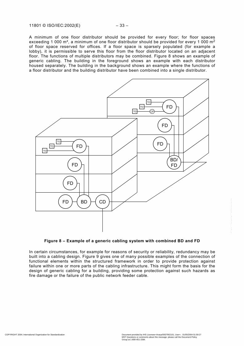
11801 © ISO/IEC:2002(E) – 33 –
A minimum of one floor distributor should be provided for every floor; for floor spacesexceeding 1 000 m², a minimum of one floor distributor should be provided for every 1 000 m2
of floor space reserved for offices. If a floor space is sparsely populated (for example alobby), it is permissible to serve this floor from the floor distributor located on an adjacentfloor. The functions of multiple distributors may be combined. Figure 8 shows an example ofgeneric cabling. The building in the foreground shows an example with each distributorhoused separately. The building in the background shows an example where the functions ofa floor distributor and the building distributor have been combined into a single distributor.
FD
FD
FD
TO
TO
TO
BD/FD
FD
FD
FD
TO
TO
TO
FD BD CD
CP
Figure 8 – Example of a generic cabling system with combined BD and FD
In certain circumstances, for example for reasons of security or reliability, redundancy may bebuilt into a cabling design. Figure 9 gives one of many possible examples of the connection offunctional elements within the structured framework in order to provide protection againstfailure within one or more parts of the cabling infrastructure. This might form the basis for thedesign of generic cabling for a building, providing some protection against such hazards asfire damage or the failure of the public network feeder cable.
COPYRIGHT 2004; International Organization for Standardization
Document provided by IHS Licensee=Avaya/5937902101, User=, 01/05/2004 01:59:27MST Questions or comments about this message: please call the Document PolicyGroup at 1-800-451-1584.
--``,,`,`````,,,`,,`,`,,````,-`-`,,`,,`,`,,`---

– 34 – 11801 © ISO/IEC:2002(E)
TO TOTOTOTO TO
TO TOTOTOTO TO
FD2FD1
FD1 FD2
BD2BD1
2nd floor
1st floor
Basement
Buildingentrancecable 1
Buildingentrance
cable 2
Figure 9 – Inter-relationship of functional elements in an installation with redundancy
5.7.2 Cables
For details of the use of the recommended cable types, see Clause 9. Hardware forconnecting cables shall only provide direct onward attachment for each conductor and shallnot provide contact between more than one incoming or outgoing conductor (for example,bridge taps shall not be used).
5.7.3 Work area cords and equipment cords
The work area cord connects the telecommunications outlet to the terminal equipment.Equipment cords connect equipment to the generic cabling at distributors. Both are non-permanent and can be application-specific. Assumptions have been made concerning thelength and the transmission performance of these cords; the assumptions are identified whenrelevant. The performance contribution of these cords shall be taken into account in thedesign of the channel. Clause 7 provides guidance on cord length for referenceimplementations of generic cabling.
5.7.4 Patch cords and jumpers
Patch cords and jumpers are used within cross-connect implementations at distributors. Theperformance contribution of these cords shall be taken into account in the design of thechannel. Clause 7 provides guidance on cord/jumper lengths for reference implementations ofgeneric cabling.
COPYRIGHT 2004; International Organization for Standardization
Document provided by IHS Licensee=Avaya/5937902101, User=, 01/05/2004 01:59:27MST Questions or comments about this message: please call the Document PolicyGroup at 1-800-451-1584.
--``,,`,`````,,,`,,`,`,,````,-`-`,,`,,`,`,,`---
11801 © ISO/IEC:2002(E) – 35 –
5.7.5 Telecommunications outlet (TO)
5.7.5.1 General requirements
The design of generic cabling should insure that telecommunications outlets are installedthroughout the usable floor space. A high density of telecommunications outlets will enhancethe ability of the cabling to accommodate changes. Telecommunications outlets may bepresented individually or in groups.
• Each individual work area shall be served by a minimum of two TOs. For guidance onwork area size, see ISO/IEC TR 14763-2.
• The first outlet should be for 4 pair balanced cable terminated in accordance with 10.2.1.
• The second outlet may be for:a) optical fibre orb) 4 pair balanced cable terminated in accordance with 10.2.1;
• Each telecommunications outlet shall have a permanent means of identification that isvisible to the user.
• Devices such as baluns and impedance matching adapters, if used, shall be external tothe outlet.
For balanced cable, 2 pairs per TO may be used as an alternative to 4 pairs. However, thismay require pair reassignment and will not support some applications (see Annex F). Careshould be taken that the initial pair assignment, and all subsequent changes, are recorded(see ISO/IEC 14763-1 for details of administration requirements). Pair reassignment bymeans of inserts is allowed.
5.7.5.2 Single user TO assembly
In a general implementation of generic cabling, one assembly of TOs serves a single workarea. The length of work area cords should be minimised. The implementation topology shallbe selected from the options described in 7.2.2.2 (for balanced cabling) and in 8.4 (for opticalfibre cabling). The assembly of TOs shall be known as a single user TO assembly.
In addition, where the single user TO assembly is used:
a) a single user TO assembly should be located in user-accessible locations;b) the performance contribution of work area cords, patch cords and equipment cords shall
be taken into account to ensure that the channel requirements of Clause 6 (for balancedcabling) and Clause 8 (for optical fibre cabling) are met.
5.7.5.3 Multi-user TO assembly (MUTO)
In an open office environment, a single assembly of TOs may be used to serve more than onework area. The implementation topology shall be selected from the options describedin 7.2.2.2 (for balanced cabling) and in 8.4 (for optical fibre cabling), and the assembly of TOsshall be known as a multi-user TO assembly.
In addition, where the multi-user TO assembly is used:
a) a multi-user TO assembly shall be located in an open work area so that each work areagroup is served by at least one multi-user TO assembly;
b) a multi-user TO assembly should be limited to serving a maximum of twelve work areas;c) a multi-user TO assembly should be located in user-accessible, permanent locations such
as on building columns and permanent walls;d) a multi-user TO assembly shall not be installed in obstructed areas:
COPYRIGHT 2004; International Organization for Standardization
Document provided by IHS Licensee=Avaya/5937902101, User=, 01/05/2004 01:59:27MST Questions or comments about this message: please call the Document PolicyGroup at 1-800-451-1584.
--``,,`,`````,,,`,,`,`,,````,-`-`,,`,,`,`,,`---

– 36 – 11801 © ISO/IEC:2002(E)
e) the performance contribution of work area cords, patch cords and equipment cords shallbe taken into account to ensure that the channel requirements of Clause 6 (for balancedcabling) and Clause 8 (for optical fibre cabling) are met;
f) the length of the work area cord should be limited to ensure cable management in thework area.
5.7.6 Consolidation point
The installation of a consolidation point in the horizontal cabling between the floor distributorand the telecommunications outlet may be useful in an open office environment where theflexibility of relocating TOs in the work area is required. One consolidation point is permittedbetween a FD and any TO. The consolidation point shall only contain passive connectinghardware and shall not be used for cross-connections.
In addition, where a consolidation point is used:
a) the consolidation point shall be located so that each work area group is served by at leastone consolidation point;
b) the consolidation point should be limited to serving a maximum of twelve work areas;c) a consolidation point should be located in accessible locations;d) for balanced cabling, the consolidation point shall be located so that there is at least 15 m
from it to the floor distributor;e) a consolidation point shall be part of the administration system.
5.7.7 Telecommunications rooms and equipment rooms
A telecommunications room should provide all the facilities (space, power, environmentalcontrol etc.) for passive components, active devices, and external network interfaces housedwithin it. Each telecommunications room should have direct access to the backbone cablingsubsystem.
An equipment room is an area within a building where equipment is housed. Equipment roomsare treated differently from telecommunications rooms because of the nature or complexity ofthe equipment (for example, PBXs or extensive computer installations). More than onedistributor may be located in an equipment room. If a telecommunications room serves morethan one building distributor it should be considered an equipment room.
5.7.8 Building entrance facilities
Building entrance facilities are required whenever campus backbone, public and privatenetwork cables (including from antennae) enter buildings and a transition is made to internalcables. It comprises an entrance point from the exterior of the building and the pathwayleading to the campus or building distributor. Local regulations may require special facilitieswhere the external cables are terminated. At this termination point, a change from external tointernal cable can take place.
5.7.9 External services cabling
The distance from external services to a distributor can be significant. The performance of thecable between these points should be considered as part of the initial design andimplementation of customer applications.
COPYRIGHT 2004; International Organization for Standardization
Document provided by IHS Licensee=Avaya/5937902101, User=, 01/05/2004 01:59:27MST Questions or comments about this message: please call the Document PolicyGroup at 1-800-451-1584.
--``,,`,`````,,,`,,`,`,,````,-`-`,,`,,`,`,,`---

11801 © ISO/IEC:2002(E) – 37 –
6 Performance of balanced cabling
6.1 General
This clause specifies the minimum performance of generic balanced cabling. The performanceof balanced cabling is specified for channels, permanent links and CP links (see Figure 10).
C CTO
FD C TE EQP C CC
Equipment cord
Patch cord/Jumper
CP Work area
cord CPcable
CP link
Channel
Permanent Link
C = connection
Figure 10 – Channel, permanent link and CP link of a balanced cabling
In the case of cable sharing, additional requirements should be taken into account forbalanced cabling. The additional crosstalk requirements for balanced cables are specified in9.3.
The performance specifications are separated into six classes (A to F) for balanced cabling.This allows the successful transmission of applications over channels according to Annex Fwhich lists the applications and the minimum class required.
The channel performance requirements described in this clause may be used for the designand verification of any implementation of this International Standard. Where required, the testmethods defined or referred to by this clause, shall apply. In addition, these requirements canbe used for application development and troubleshooting.
The permanent link and CP link performance requirements described in Annex A may be usedfor acceptance testing of any implementation of this International Standard. Where required,the test methods defined or referred to by Annex A, shall apply.
The specifications in this clause allow for the transmission of defined classes of applicationsover distances other than those of 7.2, and/or using media and components with differentperformances than those specified in Clauses 9, 10 and 13.
The channel, permanent link and CP link performance specification of the relevant class shallbe met for all temperatures at which the cabling is intended to operate.
There shall be adequate margins to account for temperature dependence of cablingcomponents as per relevant standards and suppliers’ instructions. In particular, considerationshould be given to measuring performance at worst case temperatures, or calculating worstcase performance based on measurements made at other temperatures.
Compatibility between cables used in the same channel or permanent link shall be maintainedthroughout the cabling system. For example, connections between cables with differentnominal impedance shall not be made.
COPYRIGHT 2004; International Organization for Standardization
Document provided by IHS Licensee=Avaya/5937902101, User=, 01/05/2004 01:59:27MST Questions or comments about this message: please call the Document PolicyGroup at 1-800-451-1584.
--``,,`,`````,,,`,,`,`,,````,-`-`,,`,,`,`,,`---

– 38 – 11801 © ISO/IEC:2002(E)
6.2 Layout
The performance of a channel is specified at and between connections to active equipment.The channel comprises only passive sections of cable, connecting hardware, work area cords,equipment cords and patch cords. The connections at the hardware interface to activeequipment are not taken into account.
Application support depends on channel performance only, which in turn depends on cablelength, number of connections, connector termination practices and workmanship, andperformance. It is possible to achieve equivalent channel performance over greater lengths bythe use of fewer connections or by using components with higher performance (see alsoAnnex G).
The performance limits for balanced cabling channels are given in 6.4. These limits arederived from the component performance limits of Clause 9 and 10 assuming the channel iscomposed of 90 m of solid conductor cable, 10 m of cord(s) and four connections (seeFigure 10).
Most class F channels are implemented with two connections only. Additional informationconcerning this implementation is given in Annex H.
Figure 11 shows an example of terminal equipment in the work area connected totransmission equipment using two different media channels, which are cascaded. In fact thereis an optical fibre channel (see Clause 8) connected via an active component in the FD to abalanced cabling channel. There are four channel interfaces; one at each end of the balancedchannel, and one at each end of the optical fibre channel.
TECTO
FD
C C
EQP C
C
C C
C
OE EQP
C
C
C C
C
CD
BD
Balanced cabling channel
Optical fibre channel
C = connection C = optional connection
= Opto-electronic equipment OE EQP
Figure 11 – Example of a system showing the location of cabling interfacesand extent of associated channels
The performance of a permanent link is specified for horizontal cabling at and between the TOand the first patch panel at the other side of the horizontal cable; it may contain a CP. Theperformance of a CP link is specified for horizontal cabling at and between the CP and thefirst patch panel at the other side of the horizontal cable. For backbone cabling the permanentlink is specified at and between the patch panels at each side of the backbone cable. Thepermanent link and CP link comprise only passive sections of cable and connecting hardware.
The performance limits for balanced cabling permanent links and CP links are given inAnnex A.
COPYRIGHT 2004; International Organization for Standardization
Document provided by IHS Licensee=Avaya/5937902101, User=, 01/05/2004 01:59:27MST Questions or comments about this message: please call the Document PolicyGroup at 1-800-451-1584.
--``,,`,`````,,,`,,`,`,,````,-`-`,,`,,`,`,,`---

11801 © ISO/IEC:2002(E) – 39 –
The performance limits for balanced cabling permanent links with maximum implementationare also given in Annex A. These limits are derived from the component performance limits ofClauses 9 and 10 assuming the permanent link is composed of 90 m of solid conductor cableand three connections (see Figure 10).
Most class F permanent links are implemented with two connections only. Additionalinformation concerning this implementation is given in Annex H.
6.3 Classification of balanced cabling
This standard specifies the following classes for balanced cabling.
Class A is specified up to 100 kHz.Class B is specified up to 1 MHz.Class C is specified up to 16 MHz.Class D is specified up to 100 MHz.Class E is specified up to 250 MHz.Class F is specified up to 600 MHz.
A Class A channel is specified so that it will provide the minimum transmission performance tosupport Class A applications. Similarly, Class B, C, D, E and F channels provide thetransmission performance to support Class B, C, D, E and F applications respectively. Linksand channels of a given class will support all applications of a lower class. Class A isregarded as the lowest class.
Channels, permanent links and CP links in the horizontal cabling shall be installed to providea minimum of Class D performance.
Annex F lists known applications by classes.
6.4 Balanced cabling performance
6.4.1 General
The parameters specified in this subclause apply to channels with screened or unscreenedcable elements, with or without an overall screen, unless explicitly stated otherwise.
The nominal impedance of channels is 100 Ω. This is achieved by suitable design andappropriate choice of cabling components (irrespective of their nominal impedance).
The requirements in this subclause are given by limits computed to one decimal place, usingthe equation for a defined frequency range. The limits for the propagation delay and delayskew are computed to three decimal places. The additional tables are for information only andhave limits derived from the relevant equation at key frequencies.
6.4.2 Return loss
The return loss requirements are applicable only to Classes C, D, E and F.
The return loss (RL) of each pair of a channel shall meet the requirements derived by theequation in Table 2.
The return loss requirements shall be met at both ends of the cabling. Return loss (RL) valuesat frequencies where the insertion loss (IL) is below 3,0 dB are for information only.
COPYRIGHT 2004; International Organization for Standardization
Document provided by IHS Licensee=Avaya/5937902101, User=, 01/05/2004 01:59:27MST Questions or comments about this message: please call the Document PolicyGroup at 1-800-451-1584.
--``,,`,`````,,,`,,`,`,,````,-`-`,,`,,`,`,,`---

– 40 – 11801 © ISO/IEC:2002(E)
When required, the return loss (RL) shall be measured according to IEC 61935-1.Terminations of 100 Ω shall be connected to the cabling elements under test at the remoteend of the channel.
Table 2 – Return loss for channel
Class FrequencyMHz
Minimum return lossdB
C 161 ≤≤ f 15,0
201 <≤ f 17,0D
10020 ≤≤ f )lg( 1030 f−
101 <≤ f 19,0
4010 <≤ f )lg( 524 f−E
25040 ≤≤ f )lg( 1032 f−
101 <≤ f 19,0
4010 <≤ f )lg( 524 f−
251,240 <≤ f )lg( 1032 f−F
600251,2 ≤≤ f 8,0
Table 3 – Informative return loss values for channel at key frequencies
Minimum return lossdBFrequency
MHzClass C Class D Class E Class F
1 15,0 17,0 19,0 19,0
16 15,0 17,0 18,0 18,0
100 N/A 10,0 12,0 12,0
250 N/A N/A 8,0 8,0
600 N/A N/A N/A 8,0
6.4.3 Insertion loss/attenuation
Previous editions of this standard use the term “attenuation”, which is still widely used in thecable industry. However, due to impedance mismatches in cabling systems, especially athigher frequencies, this characteristic is better described as “insertion loss”. In this edition,the term “insertion loss” is adopted throughout to describe the signal attenuation over thelength of channels, links and components. Unlike attenuation, insertion loss does not scalelinearly with length.
The term “attenuation” is maintained for the following parameters:
• attenuation to crosstalk ratio (ACR) – see 6.4.5;
• unbalanced attenuation – see 6.4.14;
• coupling attenuation – see 6.4.15.
For the calculation of ACR, PS ACR, ELFEXT and PS ELFEXT, the corresponding value forinsertion loss (IL) shall be used.
COPYRIGHT 2004; International Organization for Standardization
Document provided by IHS Licensee=Avaya/5937902101, User=, 01/05/2004 01:59:27MST Questions or comments about this message: please call the Document PolicyGroup at 1-800-451-1584.
--``,,`,`````,,,`,,`,`,,````,-`-`,,`,,`,`,,`---
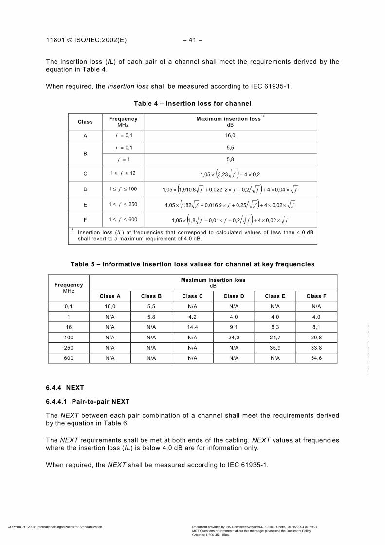
11801 © ISO/IEC:2002(E) – 41 –
The insertion loss (IL) of each pair of a channel shall meet the requirements derived by theequation in Table 4.
When required, the insertion loss shall be measured according to IEC 61935-1.
Table 4 – Insertion loss for channel
Class FrequencyMHz
Maximum insertion loss a
dB
A 0,1=f 16,0
0,1=f 5,5B
1=f 5,8
C 161 ≤≤ f ( ) 0,243,231,05 ×+× f
D 1001 ≤≤ f ( ) ffff ××++×+× 0,0440,22 0,0228 1,9101,05
E 2501 ≤≤ f ( ) ffff ××++×+× 0,0240,259 0,0161,821,05
F 6001 ≤≤ f ( ) ffff ××++×+× 0,0240,20,011,81,05a
Insertion loss (IL) at frequencies that correspond to calculated values of less than 4,0 dBshall revert to a maximum requirement of 4,0 dB.
Table 5 – Informative insertion loss values for channel at key frequencies
Maximum insertion lossdBFrequency
MHzClass A Class B Class C Class D Class E Class F
0,1 16,0 5,5 N/A N/A N/A N/A
1 N/A 5,8 4,2 4,0 4,0 4,0
16 N/A N/A 14,4 9,1 8,3 8,1
100 N/A N/A N/A 24,0 21,7 20,8
250 N/A N/A N/A N/A 35,9 33,8
600 N/A N/A N/A N/A N/A 54,6
6.4.4 NEXT
6.4.4.1 Pair-to-pair NEXT
The NEXT between each pair combination of a channel shall meet the requirements derivedby the equation in Table 6.
The NEXT requirements shall be met at both ends of the cabling. NEXT values at frequencieswhere the insertion loss (IL) is below 4,0 dB are for information only.
When required, the NEXT shall be measured according to IEC 61935-1.
COPYRIGHT 2004; International Organization for Standardization
Document provided by IHS Licensee=Avaya/5937902101, User=, 01/05/2004 01:59:27MST Questions or comments about this message: please call the Document PolicyGroup at 1-800-451-1584.
--``,,`,`````,,,`,,`,`,,````,-`-`,,`,,`,`,,`---

– 42 – 11801 © ISO/IEC:2002(E)
Table 6 – NEXT for channel
Class FrequencyMHz
Minimum NEXTdB
A 0,1=f 27,0
B 10,1 ≤≤ f )( lg 15 25 f-
C 161 ≤≤ f )( lg 16,4 39,1 f-
D 1001 ≤≤ f
−
−
×+−−
− 20)( lg 20 83
10220)( lg 15 65,3
10 lg 20ff
a
E 2501 ≤≤ f
−
−
×+−−
20)( lg 2094
10220)( lg 1574,3
10 log 20-ff
b
F 6001 ≤≤ f
−−
×+−−
− 20)( lg 15102,4
10220)( lg 15102,4
10 lg 20ff
b
a NEXT at frequencies that correspond to calculated values of greater than 60,0 dB shall revert to a minimumrequirement of 60,0 dB.
b NEXT at frequencies that correspond to calculated values of greater than 65,0 dB shall revert to a minimumrequirement of 65,0 dB.
Table 7 – Informative NEXT values for channel at key frequencies
Minimum channel NEXTdB
FrequencyMHz
Class A Class B Class C Class D Class E Class F
0,1 27,0 40,0 N/A N/A N/A N/A
1 N/A 25,0 39,1 60,0 65,0 65,0
16 N/A N/A 19,4 43,6 53,2 65,0
100 N/A N/A N/A 30,1 39,9 62,9
250 N/A N/A N/A N/A 33,1 56,9
600 N/A N/A N/A N/A N/A 51,2
6.4.4.2 Power sum NEXT (PS NEXT)
The PS NEXT requirements are applicable only to Classes D, E and F.
The PS NEXT of each pair of a channel shall meet the requirements derived by the equationin Table 8.
The PS NEXT requirements shall be met at both ends of the cabling. PS NEXT values atfrequencies where the insertion loss (IL) is below 4,0 dB are for information only.
COPYRIGHT 2004; International Organization for Standardization
Document provided by IHS Licensee=Avaya/5937902101, User=, 01/05/2004 01:59:27MST Questions or comments about this message: please call the Document PolicyGroup at 1-800-451-1584.
--``,,`,`````,,,`,,`,`,,````,-`-`,,`,,`,`,,`---
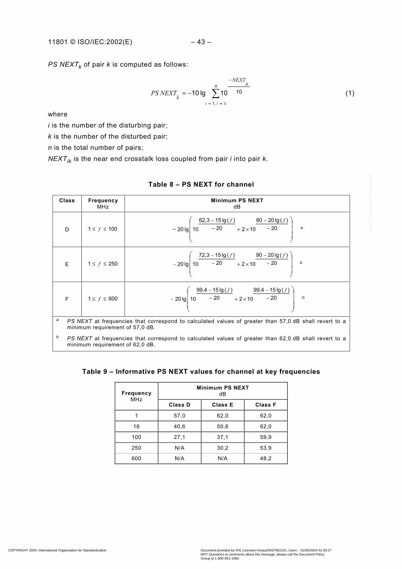
11801 © ISO/IEC:2002(E) – 43 –
PS NEXTk of pair k is computed as follows:
∑≠=
−
−=n
NEXT
kkii
ik
PS NEXT1,
1010lg 10 (1)
wherei is the number of the disturbing pair;k is the number of the disturbed pair;n is the total number of pairs;NEXTik is the near end crosstalk loss coupled from pair i into pair k.
Table 8 – PS NEXT for channel
Class FrequencyMHz
Minimum PS NEXTdB
D 1001 ≤≤ f
− −
−
×+−−
20)( lg 2080
10220)( lg 1562,3
10 lg 20ff
a
E 2501 ≤≤ f
−
−
×+−−
− 20)( lg 2090
10220)( lg 1572,3
10 lg 20ff
b
F 6001 ≤≤ f
−−
×+−−
− 20)( lg 1599,4
10220)( lg 1599,4
10 lg 20ff
b
a PS NEXT at frequencies that correspond to calculated values of greater than 57,0 dB shall revert to aminimum requirement of 57,0 dB.
b PS NEXT at frequencies that correspond to calculated values of greater than 62,0 dB shall revert to aminimum requirement of 62,0 dB.
Table 9 – Informative PS NEXT values for channel at key frequencies
Minimum PS NEXTdBFrequency
MHzClass D Class E Class F
1 57,0 62,0 62,0
16 40,6 50,6 62,0
100 27,1 37,1 59,9
250 N/A 30,2 53,9
600 N/A N/A 48,2
COPYRIGHT 2004; International Organization for Standardization
Document provided by IHS Licensee=Avaya/5937902101, User=, 01/05/2004 01:59:27MST Questions or comments about this message: please call the Document PolicyGroup at 1-800-451-1584.
--``,,`,`````,,,`,,`,`,,````,-`-`,,`,,`,`,,`---

– 44 – 11801 © ISO/IEC:2002(E)
6.4.5 Attenuation to crosstalk ratio (ACR)
The ACR requirements are applicable only to Classes D, E and F.
6.4.5.1 Pair-to-pair ACR
Pair-to-pair ACR is the difference between the pair-to-pair NEXT and the insertion loss (IL) ofthe cabling in dB.
The ACR of each pair combination of a channel shall meet the difference of the NEXTrequirement of Table 6 and the insertion loss (IL) requirement of Table 4 of the respectiveclass.
The ACR requirements shall be met at both ends of the cabling.
ACRik of pairs i and k is computed as follows:
kikik ILNEXTACR −= (2)
wherei is the number of the disturbing pair;k is the number of the disturbed pair;NEXTik is the near end crosstalk loss coupled from pair i into pair k;ILk is the insertion loss of pair k. When required, it shall be measured according to
IEC 61935-1.
Table 10 – Informative ACR values for channel at key frequencies
Minimum ACRdBFrequency
MHzClass D Class E Class F
1 56,0 61,0 61,0
16 34,5 44,9 56,9
100 6,1 18,2 42,1
250 N/A –2,8 23,1
600 N/A N/A –3,4
6.4.5.2 Power sum ACR (PS ACR)
The PS ACR of each pair of a channel shall meet the difference of the PS NEXT requirementof Table 8 and the insertion loss (IL) requirement of Table 4 of the respective class.
The PS ACR requirements shall be met at both ends of the cabling.
COPYRIGHT 2004; International Organization for Standardization
Document provided by IHS Licensee=Avaya/5937902101, User=, 01/05/2004 01:59:27MST Questions or comments about this message: please call the Document PolicyGroup at 1-800-451-1584.
--``,,`,`````,,,`,,`,`,,````,-`-`,,`,,`,`,,`---
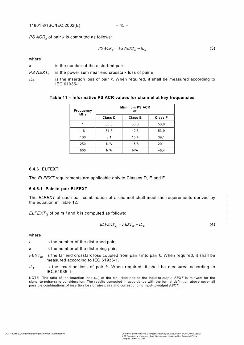
11801 © ISO/IEC:2002(E) – 45 –
PS ACRk of pair k is computed as follows:
kkk ILPS NEXTPS ACR −= (3)
wherek is the number of the disturbed pair;PS NEXTk is the power sum near end crosstalk loss of pair k;ILk is the insertion loss of pair k. When required, it shall be measured according to
IEC 61935-1.
Table 11 – Informative PS ACR values for channel at key frequencies
Minimum PS ACRdBFrequency
MHzClass D Class E Class F
1 53,0 58,0 58,0
16 31,5 42,3 53,9
100 3,1 15,4 39,1
250 N/A –5,8 20,1
600 N/A N/A –6,4
6.4.6 ELFEXT
The ELFEXT requirements are applicable only to Classes D, E and F.
6.4.6.1 Pair-to-pair ELFEXT
The ELFEXT of each pair combination of a channel shall meet the requirements derived bythe equation in Table 12.
ELFEXTik of pairs i and k is computed as follows:
kikik ILFEXTELFEXT −= (4)
wherei is the number of the disturbed pair;k is the number of the disturbing pair;FEXTik is the far end crosstalk loss coupled from pair i into pair k. When required, it shall be
measured according to IEC 61935-1.ILk is the insertion loss of pair k. When required, it shall be measured according to
IEC 61935-1.NOTE The ratio of the insertion loss (IL) of the disturbed pair to the input-to-output FEXT is relevant for thesignal-to-noise-ratio consideration. The results computed in accordance with the formal definition above cover allpossible combinations of insertion loss of wire pairs and corresponding input-to-output FEXT.
COPYRIGHT 2004; International Organization for Standardization
Document provided by IHS Licensee=Avaya/5937902101, User=, 01/05/2004 01:59:27MST Questions or comments about this message: please call the Document PolicyGroup at 1-800-451-1584.
--``,,`,`````,,,`,,`,`,,````,-`-`,,`,,`,`,,`---

– 46 – 11801 © ISO/IEC:2002(E)
Table 12 – ELFEXT for channel
Class FrequencyMHz
Minimum ELFEXT a
dB
D 1001 ≤≤ f
−−
×+−−
− 20)( lg 2075,1
10420)( lg 2063,8
10 lg 20ff
b
E 2501 ≤≤ f
−−
×+−−
− 20)( lg 2083,1
10420)( lg 2067,8
10 lg 20ff
c
F 6001 ≤≤ f
−
−
×+−−
− 20)( lg 1590
10420)( lg 2094
10 lg 20ff
c
a ELFEXT at frequencies that correspond to measured FEXT values of greater than 70,0 dB are forinformation only.
b ELFEXT at frequencies that correspond to calculated values of greater than 60,0 dB shall revert to aminimum requirement of 60,0 dB.
c ELFEXT at frequencies that correspond to calculated values of greater than 65,0 dB shall revert to aminimum requirement of 65,0 dB.
Table 13 – Informative ELFEXT values for channel at key frequencies
Minimum ELFEXTdBFrequency
MHzClass D Class E Class F
1 57,4 63,3 65,0
16 33,3 39,2 57,5
100 17,4 23,3 44,4
250 N/A 15,3 37,8
600 N/A N/A 31,3
6.4.6.2 Power sum ELFEXT (PS ELFEXT)
The PS ELFEXT of each pair of a channel shall meet the requirements derived by theequation in Table 14.
PS ELFEXTk of pair k is computed as follows:
∑≠=
−
−=n
ELFEXT
PS ELFEXTkii
ik
k1,
1010lg 10 (5)
wherei is the number of the disturbing pair;k is the number of the disturbed pair;N is the total number of pairs;ELFEXTik is the equal level far end crosstalk loss coupled from pair i into pair k.
COPYRIGHT 2004; International Organization for Standardization
Document provided by IHS Licensee=Avaya/5937902101, User=, 01/05/2004 01:59:27MST Questions or comments about this message: please call the Document PolicyGroup at 1-800-451-1584.
--``,,`,`````,,,`,,`,`,,````,-`-`,,`,,`,`,,`---
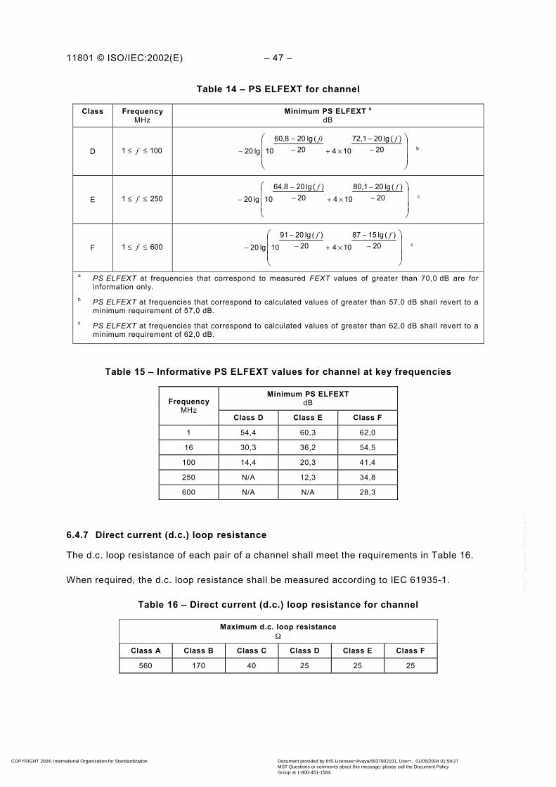
11801 © ISO/IEC:2002(E) – 47 –
Table 14 – PS ELFEXT for channel
Class FrequencyMHz
Minimum PS ELFEXT a
dB
D 1001 ≤≤ f
−−
×+−−
− 20)( lg 2072,1
10420( lg 2060,8
10 lg 20ff)
b
E 2501 ≤≤ f
−−
×+−−
− 20)( lg 2080,1
10420)( lg 2064,8
10 lg 20ff
c
F 6001 ≤≤ f
−
−
×+−−
− 20)( lg 1587
10420)( lg 2091
10 lg 20ff
c
a PS ELFEXT at frequencies that correspond to measured FEXT values of greater than 70,0 dB are forinformation only.
b PS ELFEXT at frequencies that correspond to calculated values of greater than 57,0 dB shall revert to aminimum requirement of 57,0 dB.
c PS ELFEXT at frequencies that correspond to calculated values of greater than 62,0 dB shall revert to aminimum requirement of 62,0 dB.
Table 15 – Informative PS ELFEXT values for channel at key frequencies
Minimum PS ELFEXTdBFrequency
MHzClass D Class E Class F
1 54,4 60,3 62,0
16 30,3 36,2 54,5
100 14,4 20,3 41,4
250 N/A 12,3 34,8
600 N/A N/A 28,3
6.4.7 Direct current (d.c.) loop resistance
The d.c. loop resistance of each pair of a channel shall meet the requirements in Table 16.
When required, the d.c. loop resistance shall be measured according to IEC 61935-1.
Table 16 – Direct current (d.c.) loop resistance for channel
Maximum d.c. loop resistanceΩ
Class A Class B Class C Class D Class E Class F
560 170 40 25 25 25
COPYRIGHT 2004; International Organization for Standardization
Document provided by IHS Licensee=Avaya/5937902101, User=, 01/05/2004 01:59:27MST Questions or comments about this message: please call the Document PolicyGroup at 1-800-451-1584.
--``,,`,`````,,,`,,`,`,,````,-`-`,,`,,`,`,,`---
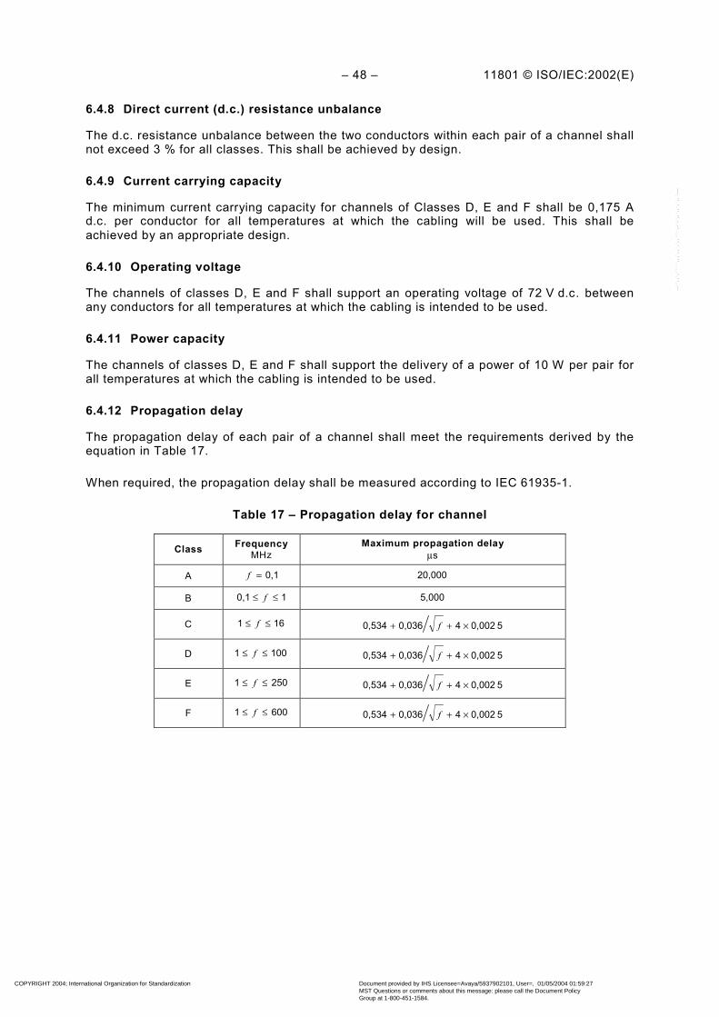
– 48 – 11801 © ISO/IEC:2002(E)
6.4.8 Direct current (d.c.) resistance unbalance
The d.c. resistance unbalance between the two conductors within each pair of a channel shallnot exceed 3 % for all classes. This shall be achieved by design.
6.4.9 Current carrying capacity
The minimum current carrying capacity for channels of Classes D, E and F shall be 0,175 Ad.c. per conductor for all temperatures at which the cabling will be used. This shall beachieved by an appropriate design.
6.4.10 Operating voltage
The channels of classes D, E and F shall support an operating voltage of 72 V d.c. betweenany conductors for all temperatures at which the cabling is intended to be used.
6.4.11 Power capacity
The channels of classes D, E and F shall support the delivery of a power of 10 W per pair forall temperatures at which the cabling is intended to be used.
6.4.12 Propagation delay
The propagation delay of each pair of a channel shall meet the requirements derived by theequation in Table 17.
When required, the propagation delay shall be measured according to IEC 61935-1.
Table 17 – Propagation delay for channel
Class FrequencyMHz
Maximum propagation delayµs
A 0,1=f 20,000
B 10,1 ≤≤ f 5,000
C 161 ≤≤ f 5 0,00240,0360,534 ×++ f
D 1001 ≤≤ f 5 0,00240,0360,534 ×++ f
E 2501 ≤≤ f 5 0,00240,0360,534 ×++ f
F 6001 ≤≤ f 5 0,00240,0360,534 ×++ f
COPYRIGHT 2004; International Organization for Standardization
Document provided by IHS Licensee=Avaya/5937902101, User=, 01/05/2004 01:59:27MST Questions or comments about this message: please call the Document PolicyGroup at 1-800-451-1584.
--``,,`,`````,,,`,,`,`,,````,-`-`,,`,,`,`,,`---
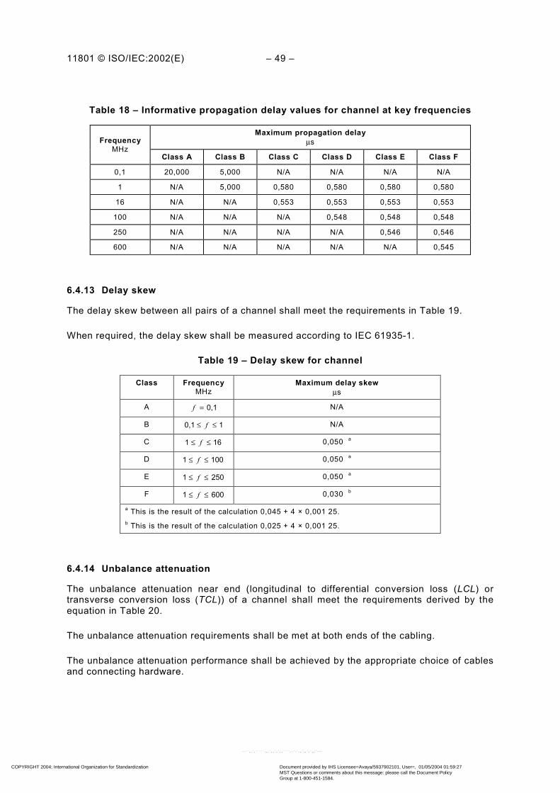
11801 © ISO/IEC:2002(E) – 49 –
Table 18 – Informative propagation delay values for channel at key frequencies
Maximum propagation delayµsFrequency
MHzClass A Class B Class C Class D Class E Class F
0,1 20,000 5,000 N/A N/A N/A N/A
1 N/A 5,000 0,580 0,580 0,580 0,580
16 N/A N/A 0,553 0,553 0,553 0,553
100 N/A N/A N/A 0,548 0,548 0,548
250 N/A N/A N/A N/A 0,546 0,546
600 N/A N/A N/A N/A N/A 0,545
6.4.13 Delay skew
The delay skew between all pairs of a channel shall meet the requirements in Table 19.
When required, the delay skew shall be measured according to IEC 61935-1.
Table 19 – Delay skew for channel
Class FrequencyMHz
Maximum delay skewµs
A 0,1=f N/A
B 10,1 ≤≤ f N/A
C 161 ≤≤ f 0,050 a
D 1001 ≤≤ f 0,050 a
E 2501 ≤≤ f 0,050 a
F 6001 ≤≤ f 0,030 b
a This is the result of the calculation 0,045 + 4 × 0,001 25.b This is the result of the calculation 0,025 + 4 × 0,001 25.
6.4.14 Unbalance attenuation
The unbalance attenuation near end (longitudinal to differential conversion loss (LCL) ortransverse conversion loss (TCL)) of a channel shall meet the requirements derived by theequation in Table 20.
The unbalance attenuation requirements shall be met at both ends of the cabling.
The unbalance attenuation performance shall be achieved by the appropriate choice of cablesand connecting hardware.
COPYRIGHT 2004; International Organization for Standardization
Document provided by IHS Licensee=Avaya/5937902101, User=, 01/05/2004 01:59:27MST Questions or comments about this message: please call the Document PolicyGroup at 1-800-451-1584.
--``,,`,`````,,,`,,`,`,,````,-`-`,,`,,`,`,,`---

– 50 – 11801 © ISO/IEC:2002(E)
Table 20 – Unbalance attenuation for channel
Class FrequencyMHz
Maximum unbalance attenuationdB
A 0,1=f 30
B 0,1=f and 1 45 at 0,1 MHz; 20 at 1 MHz
C 161 ≤≤ f )( lg 5 30 f− f.f.s.
D 1001 ≤≤ f )( lg 1040 f− f.f.s.
E 2501 ≤≤ f )( lg 10 40 f− f.f.s.
F 6001 ≤≤ f )( lg 1040 f− f.f.s.
6.4.15 Coupling attenuation
The measurement of coupling attenuation for installed cabling is under development. Couplingattenuation of a sample installation may be assessed by laboratory measurements ofrepresentative samples of channels assembled, using the components and connectortermination practices in question.
7 Reference implementations for balanced cabling
7.1 General
This clause describes implementations of generic balanced cabling that utilise componentsand assemblies referenced in Clauses 9, 10 and 13. These reference implementations meetthe requirements of Clause 5 and, when installed in accordance with ISO/IEC TR 14763-2,comply with the channel performance requirements of Clause 6.
7.2 Balanced cabling
7.2.1 General
Balanced components referenced in Clauses 9 and 10 are defined in terms of impedance andcategory. In the reference implementations of this clause, the components used in eachcabling channel shall have the same nominal impedance, i.e. 100 Ω for Classes D to F and100 Ω or 120 Ω for Class A to Class C.
The implementations are based on component performance at 20 °C. The effect oftemperature on the performance of cables shall be accommodated by derating length asshown in Table 21 and Table 22.
Cables and connecting hardware of different categories may be mixed within a channel.However, the resultant cabling performance will be determined by the category of the lowestperforming component.
7.2.2 Horizontal cabling
7.2.2.1 Component choice
The selection of balanced cabling components will be determined by the class of applicationsto be supported. Refer to Annex F for guidance.
COPYRIGHT 2004; International Organization for Standardization
Document provided by IHS Licensee=Avaya/5937902101, User=, 01/05/2004 01:59:27MST Questions or comments about this message: please call the Document PolicyGroup at 1-800-451-1584.
--``,,`,`````,,,`,,`,`,,````,-`-`,,`,,`,`,,`---

11801 © ISO/IEC:2002(E) – 51 –
Using the configurations of 7.2.2.2:
• Category 5 components provide Class D balanced cabling performance;
• Category 6 components provide Class E balanced cabling performance;
• Category 7 components provide Class F balanced cabling performance.
NOTE For the relationship and requirements of classes and categories in earlier editions of this standard, seeAnnex I.
7.2.2.2 Dimensions
Figure 12 shows the models used to correlate horizontal cabling dimensions specified in thisclause with the channel specifications in Clause 6.
COPYRIGHT 2004; International Organization for Standardization
Document provided by IHS Licensee=Avaya/5937902101, User=, 01/05/2004 01:59:27MST Questions or comments about this message: please call the Document PolicyGroup at 1-800-451-1584.
--``,,`,`````,,,`,,`,`,,````,-`-`,,`,,`,`,,`---

– 52 – 11801 © ISO/IEC:2002(E)
TO
FD
C
Channel = 100 m max.
Fixed horizontal cable
TECEQP C C
Equipmentcord
Work areacord
a) Interconnect - TO Model
C = connection
TO
FD
C TECEQP C C
Work areacord
b) Crossconnect - TO Model
C
Equipmentcord
Patch cord/Jumper
Channel = 100 m max.
Fixed horizontal cable
C = connection
TO
FD
Channel = 100 m max.
TEEQP C
Work areacord
c) Interconnect - CP - TO Model
CC
Equipmentcord
Fixed horizontal cable
CCCP
CPcable
C = connection
CCTO
FD
C TEEQP C CC
Equipmentcord
Patch cord/Jumper
CP
Work areacord
CPcable
Fixed horizontal cable
Channel = 100 m max.
d) Crossconnect - CP - TO Model
C = connection
Figure 12 – Horizontal cabling models
COPYRIGHT 2004; International Organization for Standardization
Document provided by IHS Licensee=Avaya/5937902101, User=, 01/05/2004 01:59:27MST Questions or comments about this message: please call the Document PolicyGroup at 1-800-451-1584.
--``,,`,`````,,,`,,`,`,,````,-`-`,,`,,`,`,,`---

11801 © ISO/IEC:2002(E) – 53 –
Figure 12a shows a channel containing only an interconnect and a TO. Figure 12b containsan additional connection as a cross-connect. In both cases the fixed horizontal cable connectsthe FD to the TO or MUTO. The channel includes cords comprising patch cords/jumpers,equipment and work area cords.
Figure 12c shows a channel containing an interconnect, a CP and a telecommunicationsoutlet. Figure 12d contains an additional connection as a cross-connect. In both cases thefixed horizontal cable connects the FD to the CP. The channel includes cords comprisingpatch cords/jumpers, equipment and work area cords.
In addition to the cords, the channels shown in Figure 12c and Figure 12d contain a CP cable.The insertion loss specification for the CP cable may differ from that of both the fixedhorizontal cable and the cords. In order to accommodate cables used for work area cords, CPcables, patch cords, jumpers and equipment cords with different insertion loss, the length ofthe cables used within a channel shall be determined by the equations shown in Table 21.
Table 21 – Horizontal link length equations
Implementation Equation
Model Figure Class D channelsusing Category 5
components
Class E channelsusing Category 6
components
Class F channels usingCategory 7 components
Interconnect - TO 12a H = 109 – FX H = 107 – 3 a – FX H = 107 – 2 a – FX
Cross-connect - TO 12b H = 107 – FX H = 106 – 3 a – FX H = 106 – 3 a – FX
Interconnect - CP -TO 12c H = 107 – FX – CY H = 106 - 3 a – FX – CY H = 106 – 3 a – FX – CY
Cross-connect - CP - TO 12d H = 105 – FX – CY H = 105 - 3 a – FX – CY H = 105 – 3 a – FX – CY
H the maximum length of the fixed horizontal cable (m)
F combined length of patch cords/jumpers, equipment and work area cords (m)
C the length of the CP cable (m)
X the ratio of cord cable insertion loss (dB/m) to fixed horizontal cable insertion loss (dB/m) – see Clause 9
Y the ratio of CP cable insertion loss (dB/m) to fixed horizontal cable insertion loss (dB/m) – see Clause 9
NOTE For operating temperatures above 20 °C, H should be reduced by 0,2 % per °C for screened cables; 0,4 %per °C (20 °C to 40 °C) and 0,6 % per °C (>40 °C to 60 °C) for unscreened cables.a This length reduction is to provide an allocated margin to accommodate insertion loss deviation.
For the purpose of calculation in Table 21 it is assumed that:
• the flexible cable within these cords has a higher insertion loss than that used in the fixedhorizontal cable (see Clause 9);
• all the cords in the channel have a common insertion loss specification.
The following general restrictions apply:
• the physical length of the channel shall not exceed 100 m;
• the physical length of the fixed horizontal cable shall not exceed 90 m. When the totallength of patch, equipment and work area cords exceeds 10 m, the allowed physical lengthof the fixed horizontal cable shall be reduced according to Table 21;
• a consolidation point shall be located so that there is at least 15 m from it to the floordistributor;
• where a multi-user TO assembly is used, the length of the work area cord should notexceed 20 m;
• the length of patch cords/jumper cables should not exceed 5 m.
COPYRIGHT 2004; International Organization for Standardization
Document provided by IHS Licensee=Avaya/5937902101, User=, 01/05/2004 01:59:27MST Questions or comments about this message: please call the Document PolicyGroup at 1-800-451-1584.
--``,,`,`````,,,`,,`,`,,````,-`-`,,`,,`,`,,`---
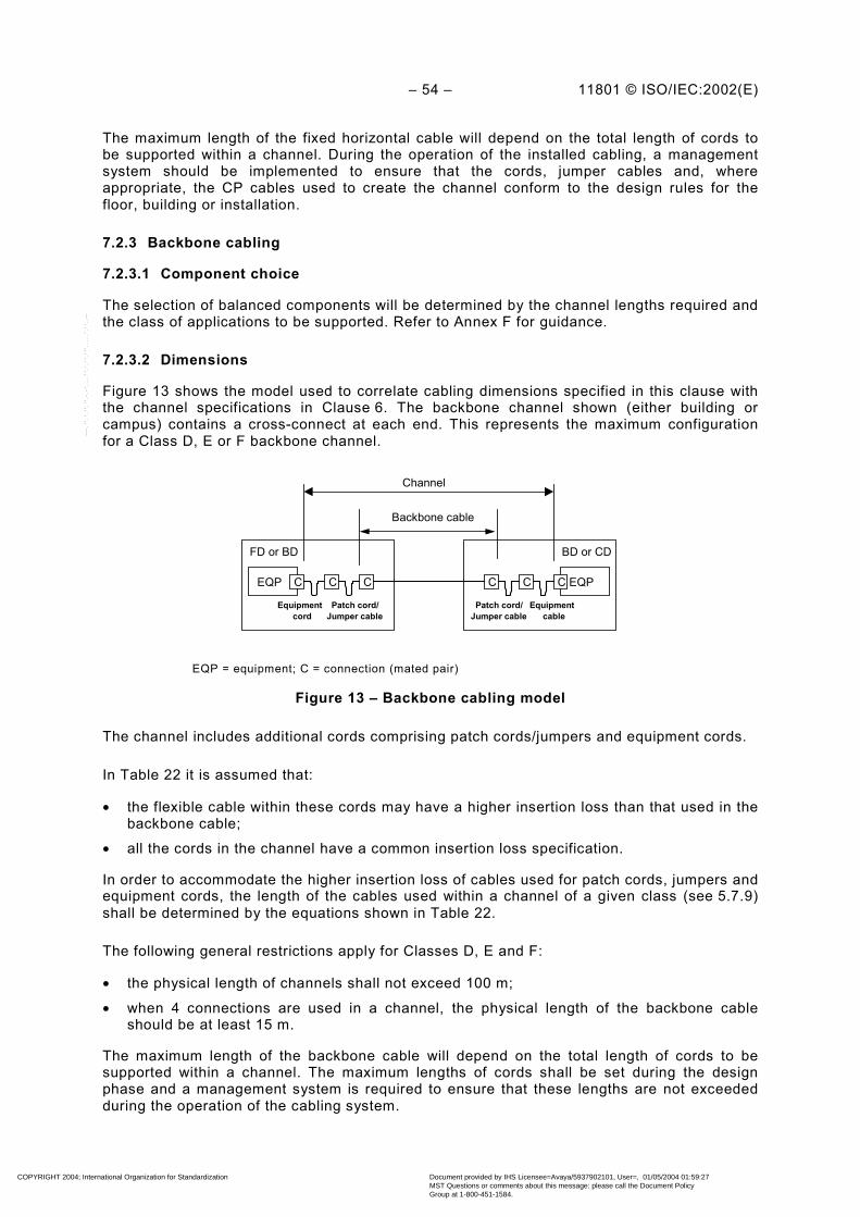
– 54 – 11801 © ISO/IEC:2002(E)
The maximum length of the fixed horizontal cable will depend on the total length of cords tobe supported within a channel. During the operation of the installed cabling, a managementsystem should be implemented to ensure that the cords, jumper cables and, whereappropriate, the CP cables used to create the channel conform to the design rules for thefloor, building or installation.
7.2.3 Backbone cabling
7.2.3.1 Component choice
The selection of balanced components will be determined by the channel lengths required andthe class of applications to be supported. Refer to Annex F for guidance.
7.2.3.2 Dimensions
Figure 13 shows the model used to correlate cabling dimensions specified in this clause withthe channel specifications in Clause 6. The backbone channel shown (either building orcampus) contains a cross-connect at each end. This represents the maximum configurationfor a Class D, E or F backbone channel.
CEQP C C Equipment
cord Patch cord/Jumper cable
C EQP C C
Equipment cable
Patch cord/ Jumper cable
Channel
Backbone cable
FD or BD BD or CD
EQP = equipment; C = connection (mated pair)
Figure 13 – Backbone cabling model
The channel includes additional cords comprising patch cords/jumpers and equipment cords.
In Table 22 it is assumed that:
• the flexible cable within these cords may have a higher insertion loss than that used in thebackbone cable;
• all the cords in the channel have a common insertion loss specification.
In order to accommodate the higher insertion loss of cables used for patch cords, jumpers andequipment cords, the length of the cables used within a channel of a given class (see 5.7.9)shall be determined by the equations shown in Table 22.
The following general restrictions apply for Classes D, E and F:
• the physical length of channels shall not exceed 100 m;
• when 4 connections are used in a channel, the physical length of the backbone cableshould be at least 15 m.
The maximum length of the backbone cable will depend on the total length of cords to besupported within a channel. The maximum lengths of cords shall be set during the designphase and a management system is required to ensure that these lengths are not exceededduring the operation of the cabling system.
COPYRIGHT 2004; International Organization for Standardization
Document provided by IHS Licensee=Avaya/5937902101, User=, 01/05/2004 01:59:27MST Questions or comments about this message: please call the Document PolicyGroup at 1-800-451-1584.
--``,,`,`````,,,`,,`,`,,````,-`-`,,`,,`,`,,`---

11801 © ISO/IEC:2002(E) – 55 –
Table 22 – Backbone link length equations
Class
ComponentCategory
Asee a
Bsee a
Csee a
Dsee a
Esee a
Fsee a
5 2 000 B = 250 – FX B = 170 – FX B = 105 – FX – –
6 2 000 B = 260 – FX B = 185 – FX B = 111 – FX B = 105 – 3 b – FX –
7 2 000 B = 260 – FX B = 190 – FX B = 115 – FX B = 107 – 3 b – FX B = 105 – 3 b – FX
B the maximum length of the backbone cable (m)
F combined length of patch cords/jumpers and equipment cords (m)
X the ratio of cord cable insertion loss (dB/m) to backbone cable insertion loss (dB/m) – see Clause 9
NOTE 1 Where channels contain a different number of connections than in the model shown in Figure 13, the fixedcable length shall be reduced (where more connections exist) or may be increased (where fewer connections exist) by2 m per connection for category 5 cables and 1 m per connection for Category 6 and 7 cables. Additionally, the NEXT,Return Loss (RL) and ELFEXT performance should be verified.
NOTE 2 For operating temperatures above 20 °C, B should be reduced by 0,2 % per °C for screened cables; 0,4 % per°C (20 °C to 40 °C) and 0,6 % per °C (>40 °C to 60 °C) for unscreened cables.a Applications limited by propagation delay or skew may not be supported if channel lengths exceed 100 m.b This length reduction is to provide an allocated margin to accommodate insertion loss deviation.
8 Performance of optical fibre cabling
8.1 General
The selection of an optical fibre channel design for use within a generic cabling system shouldbe made with reference to Annex F. This standard specifies the following classes for opticalfibre cabling:
Class OF-300 channels support applications over the optical fibre types referenced inClause 9 to a minimum of 300 m
Class OF-500 channels support applications over the optical fibre types referenced inClause 9 to a minimum of 500 m
Class OF-2 000 channels support applications over the optical fibre types referenced inClause 9 to a minimum of 2 000 m
Optical fibre channels shall be comprised of components that comply with Clauses 9 and 10.These clauses specify physical construction (core/cladding diameter and numerical aperture)and transmission performance. Within the reference implementations of this clause, theoptical fibres used in each cabling channel shall have the same specification.
8.2 Component choice
The required channel lengths, applications to be supported and the life expectancy of thecabling will determine the selection of optical fibre components. The performancerequirements for optical fibre channels are based on the use of a single optical wavelength ineach specified transmission window.
The requirements for the wavelength multiplexing and demultiplexing components will befound in the application standards. There are no special requirements for generic cablingconcerning wavelength multiplexing.
COPYRIGHT 2004; International Organization for Standardization
Document provided by IHS Licensee=Avaya/5937902101, User=, 01/05/2004 01:59:27MST Questions or comments about this message: please call the Document PolicyGroup at 1-800-451-1584.
--``,,`,`````,,,`,,`,`,,````,-`-`,,`,,`,`,,`---

– 56 – 11801 © ISO/IEC:2002(E)
8.3 Channel attenuation
The channel attenuation shall not exceed the values shown in Table 23. The values are basedon a total allocation of 1,5 dB for connecting hardware. Additional connectors and splices maybe used if the power budget of the application allows. The attenuation of a channel shall bemeasured according to ISO/IEC TR 14763-3. The attenuation of channels and permanentlinks at a specified wavelength shall not exceed the sum of the specified attenuation valuesfor the components at that wavelength (where the attenuation of a length of optical fibre cableis calculated from its attenuation coefficient multiplied by its length).
Table 23 – Channel attenuation
Channel attenuationdB
Multimode Single-modeChannel
850 nm 1 300 nm 1 310 nm 1 550 nm
OF-300 2,55 1,95 1,80 1,80
OF-500 3,25 2,25 2,00 2,00
OF-2 000 8,50 4,50 3,50 3,50
8.4 Channel topology
The models of Figure 13 and Figure 14 are applicable to horizontal and backbone optical fibrecabling respectively. It should be noted that the connection system, used to terminate opticalcabling, may contain mated connecting hardware and splices (permanent or re-useable) andthat cross-connects may comprise re-useable splices.
The delivery of optical fibre to the TO would not generally require transmission equipment atthe FD (unless the design of optical fibre in the backbone cabling subsystem differs from thatin the horizontal cabling subsystem). This allows the creation of a combinedbackbone/horizontal channel as shown in Figure 14. The three diagrams show a patchedchannel, a spliced channel and a direct channel (which does not require the use of a FD).Patched and spliced channel designs are also applicable to combined campus/buildingbackbone channels and it is possible to consider a combined campus/building/horizontalchannel.
The use of permanently spliced and direct channels may be used as a means of reducingchannel attenuation and centralising the distribution of applications. However, centralising thedistribution may also result in a reduction in the overall flexibility in generic cabling.
COPYRIGHT 2004; International Organization for Standardization
Document provided by IHS Licensee=Avaya/5937902101, User=, 01/05/2004 01:59:27MST Questions or comments about this message: please call the Document PolicyGroup at 1-800-451-1584.
--``,,`,`````,,,`,,`,`,,````,-`-`,,`,,`,`,,`---
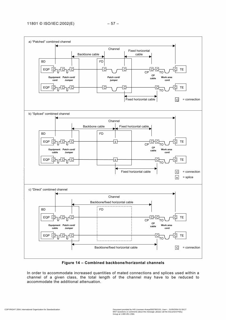
11801 © ISO/IEC:2002(E) – 57 –
EQP
Patch cord/ jumper
Channel
Backbone cable BD
C C TEC TO
Fixed horizontal cable
Work area cord
a) “Patched” combined channel
CCCP
CPcable
EQP C C C TEC TO
Fixed horizontal cable
FD
C C C
Equipment cord Patch cord/
Jumper
C C C
C = connection
EQP
Channel
Backbone cable BD
s TE C TO
Fixed horizontal cable
Work area cord
b) “Spliced” combined channel
C C CP
CPcable
EQP s C TE C TO
Fixed horizontal cable
FD
C C C
Equipment cable Patch cord/
Jumper
C C C
C = connection s = splice
C = connection
EQP
Channel
Backbone/fixed horizontal cable BD
TE C TO
Work area cord
c) “Direct” combined channel
C C CP
CP cable
EQP C TE C TO
Backbone/fixed horizontal cable
FD
C C C
Equipment cable Patch cord/
Jumper
C C C
Figure 14 – Combined backbone/horizontal channels
In order to accommodate increased quantities of mated connections and splices used within achannel of a given class, the total length of the channel may have to be reduced toaccommodate the additional attenuation.
COPYRIGHT 2004; International Organization for Standardization
Document provided by IHS Licensee=Avaya/5937902101, User=, 01/05/2004 01:59:27MST Questions or comments about this message: please call the Document PolicyGroup at 1-800-451-1584.
--``,,`,`````,,,`,,`,`,,````,-`-`,,`,,`,`,,`---
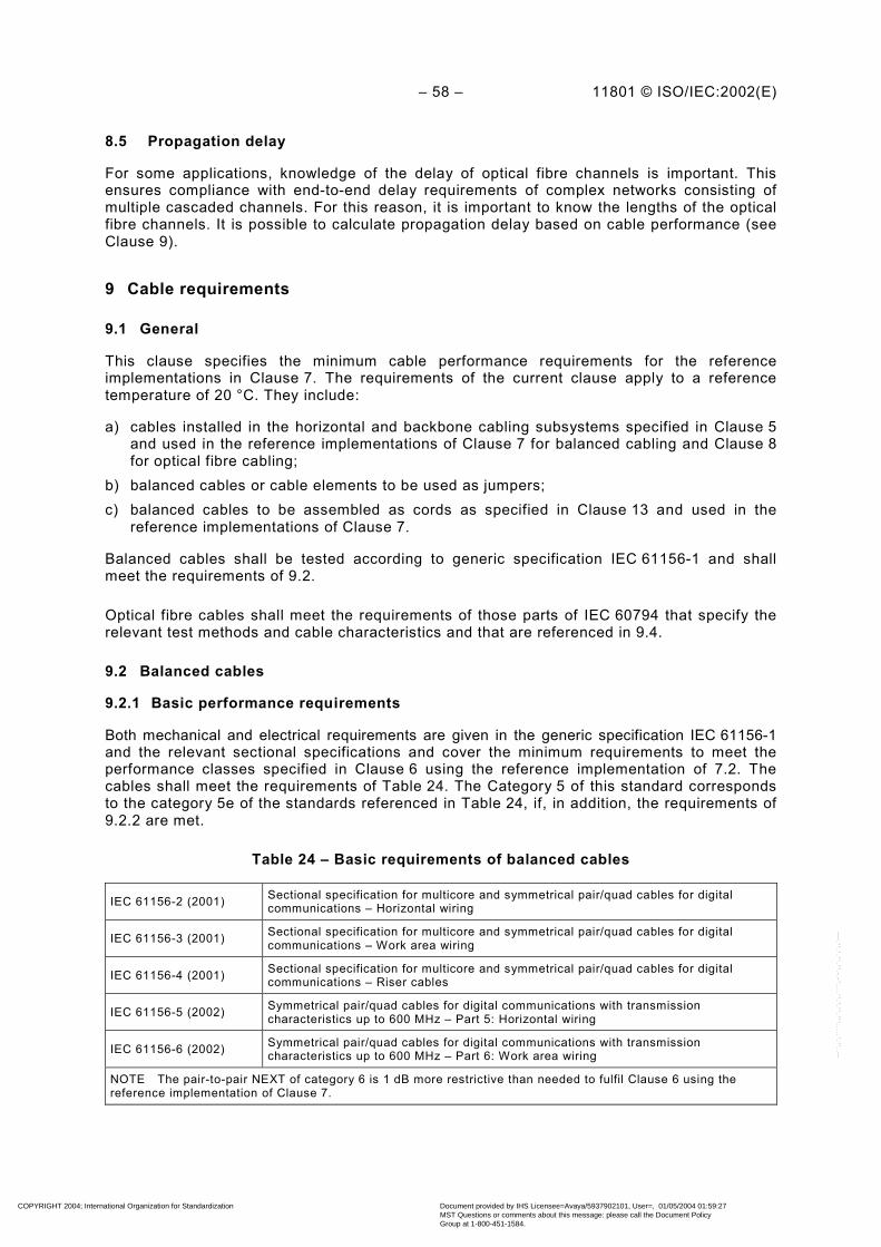
– 58 – 11801 © ISO/IEC:2002(E)
8.5 Propagation delay
For some applications, knowledge of the delay of optical fibre channels is important. Thisensures compliance with end-to-end delay requirements of complex networks consisting ofmultiple cascaded channels. For this reason, it is important to know the lengths of the opticalfibre channels. It is possible to calculate propagation delay based on cable performance (seeClause 9).
9 Cable requirements
9.1 General
This clause specifies the minimum cable performance requirements for the referenceimplementations in Clause 7. The requirements of the current clause apply to a referencetemperature of 20 °C. They include:
a) cables installed in the horizontal and backbone cabling subsystems specified in Clause 5and used in the reference implementations of Clause 7 for balanced cabling and Clause 8for optical fibre cabling;
b) balanced cables or cable elements to be used as jumpers;c) balanced cables to be assembled as cords as specified in Clause 13 and used in the
reference implementations of Clause 7.
Balanced cables shall be tested according to generic specification IEC 61156-1 and shallmeet the requirements of 9.2.
Optical fibre cables shall meet the requirements of those parts of IEC 60794 that specify therelevant test methods and cable characteristics and that are referenced in 9.4.
9.2 Balanced cables
9.2.1 Basic performance requirements
Both mechanical and electrical requirements are given in the generic specification IEC 61156-1and the relevant sectional specifications and cover the minimum requirements to meet theperformance classes specified in Clause 6 using the reference implementation of 7.2. Thecables shall meet the requirements of Table 24. The Category 5 of this standard correspondsto the category 5e of the standards referenced in Table 24, if, in addition, the requirements of9.2.2 are met.
Table 24 – Basic requirements of balanced cables
IEC 61156-2 (2001) Sectional specification for multicore and symmetrical pair/quad cables for digitalcommunications – Horizontal wiring
IEC 61156-3 (2001) Sectional specification for multicore and symmetrical pair/quad cables for digitalcommunications – Work area wiring
IEC 61156-4 (2001) Sectional specification for multicore and symmetrical pair/quad cables for digitalcommunications – Riser cables
IEC 61156-5 (2002) Symmetrical pair/quad cables for digital communications with transmissioncharacteristics up to 600 MHz – Part 5: Horizontal wiring
IEC 61156-6 (2002) Symmetrical pair/quad cables for digital communications with transmissioncharacteristics up to 600 MHz – Part 6: Work area wiring
NOTE The pair-to-pair NEXT of category 6 is 1 dB more restrictive than needed to fulfil Clause 6 using thereference implementation of Clause 7.
COPYRIGHT 2004; International Organization for Standardization
Document provided by IHS Licensee=Avaya/5937902101, User=, 01/05/2004 01:59:27MST Questions or comments about this message: please call the Document PolicyGroup at 1-800-451-1584.
--``,,`,`````,,,`,,`,`,,````,-`-`,,`,,`,`,,`---

11801 © ISO/IEC:2002(E) – 59 –
9.2.2 Additional requirements
9.2.2.1 General
The additional mechanical and electrical requirements given in this subclause shall be met.Measurements shall be performed according to IEC 61156-1. In case of conflict withreferenced standards, the limits in this standard apply.
9.2.2.2 Mechanical characteristics of balanced cables
Table 25 – Mechanical characteristics of balanced cables
Cable characteristics Units Requirements
1.1 Diameter of conductora mm 0,4 to 0,8
1.2 Diameter over-insulated conductorb mm ≤1,6
1.3 Outer diameter of backbone cablec mm ≤90
1.4 Temperature range without mechanicalor electrical degradation °C installation: 0 to +50
operation: –20 to +60
1.5 Minimum bending radius (afterinstallation)d
25 mm for four-pair cables with a diameter up to 6 mm50 mm for four-pair cables with a diameter over 6 mm
a Conductor diameters below 0,5 mm and above 0,65 mm may not be compatible with all connectinghardware.
b Diameters over the insulated conductor up to 1,7 mm may be used if they meet all other performancerequirements. These cables may not be compatible with all connecting hardware.
c Should be minimised to make best use of duct and cross-connect capacity (see Clause 10).d For minimum bending radius requirements during installation refer to manufacturer’s recommendations.
9.2.2.3 Mean characteristic impedance
Refer to 3.3.6.2 of IEC 61156-5 measured according to 3.3.6.2.3 method A of IEC 61156-1 ona standard length of 100 m. The nominal impedance shall be 100 Ω.
Alternate test methodologies that have been shown to correlate with these requirements mayalso be used.
9.2.2.4 Attenuation
For the attenuation of Category 5 cable the constants specified in 3.3.2.2 of IEC 61156-5 shallbe used. They result in a lower attenuation than given in table 4 of 3.3.2.1 of IEC 61156-5, forexample in 21,3 dB/100 m at 100 MHz.
Calculations that result in attenuation below 4 dB shall revert to a requirement of 4 dB.
9.2.2.5 ELFEXT and PS ELFEXT
Refer to 3.3.5 of IEC 61156-5 with the additional requirement, that ELFEXT and PS ELFEXTshall be met from 1 MHz up to the highest specified frequency.
If FEXT is greater than 70 dB, ELFEXT and PS ELFEXT need not be measured.
9.2.2.6 Current carrying capacity
Minimum d.c. current carrying capacity per conductor shall be 175 mA.
This shall be supported at a maximum ambient temperature of 60 °C; conformance shall beachieved by design. An IEC test reference is under development.
COPYRIGHT 2004; International Organization for Standardization
Document provided by IHS Licensee=Avaya/5937902101, User=, 01/05/2004 01:59:27MST Questions or comments about this message: please call the Document PolicyGroup at 1-800-451-1584.
--``,,`,`````,,,`,,`,`,,````,-`-`,,`,,`,`,,`---

– 60 – 11801 © ISO/IEC:2002(E)
9.2.2.7 Coupling attenuation
Refer to 3.3.9 of IEC 61156-5 with the additional requirement, that for screened cables type IIshall be met.
9.2.2.8 Transfer impedance
Screened cables shall meet the requirements of grade 2 in table 2 of IEC 61156-5.
9.2.3 Additional performance requirements for flexible cables
This clause covers additional requirements for cables used for patch cords, for work area andfor equipment cords for use with balanced cabling. The electrical performance of these cablesshall meet the general requirements for balanced cables as specified in 9.2.2 for therespective category with exception of attenuation, d.c. loop resistance and return loss (RL),which are specified in this subclause.
The attenuation in dB/100 m and d.c. loop resistance shall not be more than 50 % higher thanspecified in 9.2.2. Consider 7.2 for additional length restrictions.
NOTE Return loss (RL) shall be measured on a test length of 100 m. Alternate test methodologies that have beenshown to correlate with these requirements may also be used.
9.3 Additional crosstalk considerations for cable sharing in balanced cables
9.3.1 General
This subclause covers cabling system implementations that may lead to the presence ofmultiple signals on the same cable.
Backbone cables required to support multiple signals shall meet the requirements of 9.3.2.
In the horizontal cabling subsystem, when multiple telecommunications outlets are served bya single cable, the near-end crosstalk of cable elements that extend to any two or moreoutlets shall meet the requirements of 9.3.3. The requirements of 9.3.3 also apply betweenunits of hybrid and multi-unit cables used in either the horizontal or backbone subsystems.
9.3.2 Power summation in backbone cables
Examples of the types of cables covered by this clause include cables with two or moreelements within a cable unit that are used for backbone subsystems. Cables according to therequirements of this clause shall meet the respective requirements of 9.2. These cables shalladditionally meet the PS NEXT requirements for crosstalk in bundled cable, i.e. 3.3.10 ofIEC 61156-5.
NOTE 1 The specification in IEC 61156-5:2002 is more demanding by 2 dB than the original ISO/IEC requirement.
NOTE 2 PS NEXT takes the total crosstalk power into account. Therefore a higher count of adjacent pairsrequires a higher pair-pair NEXT to achieve the same PS NEXT.
9.3.3 Hybrid, multi-unit and cables connected to more than one TO
Examples of the types of cables that are covered by this clause include hybrid cables andmulti-unit cables and any cable connected to more than one TO. The units may be of thesame type or of different types, and of the same category or of different categories. Cablesrequired to meet this clause shall also meet the requirements for the corresponding cable typegiven in 9.2.
COPYRIGHT 2004; International Organization for Standardization
Document provided by IHS Licensee=Avaya/5937902101, User=, 01/05/2004 01:59:27MST Questions or comments about this message: please call the Document PolicyGroup at 1-800-451-1584.
--``,,`,`````,,,`,,`,`,,````,-`-`,,`,,`,`,,`---
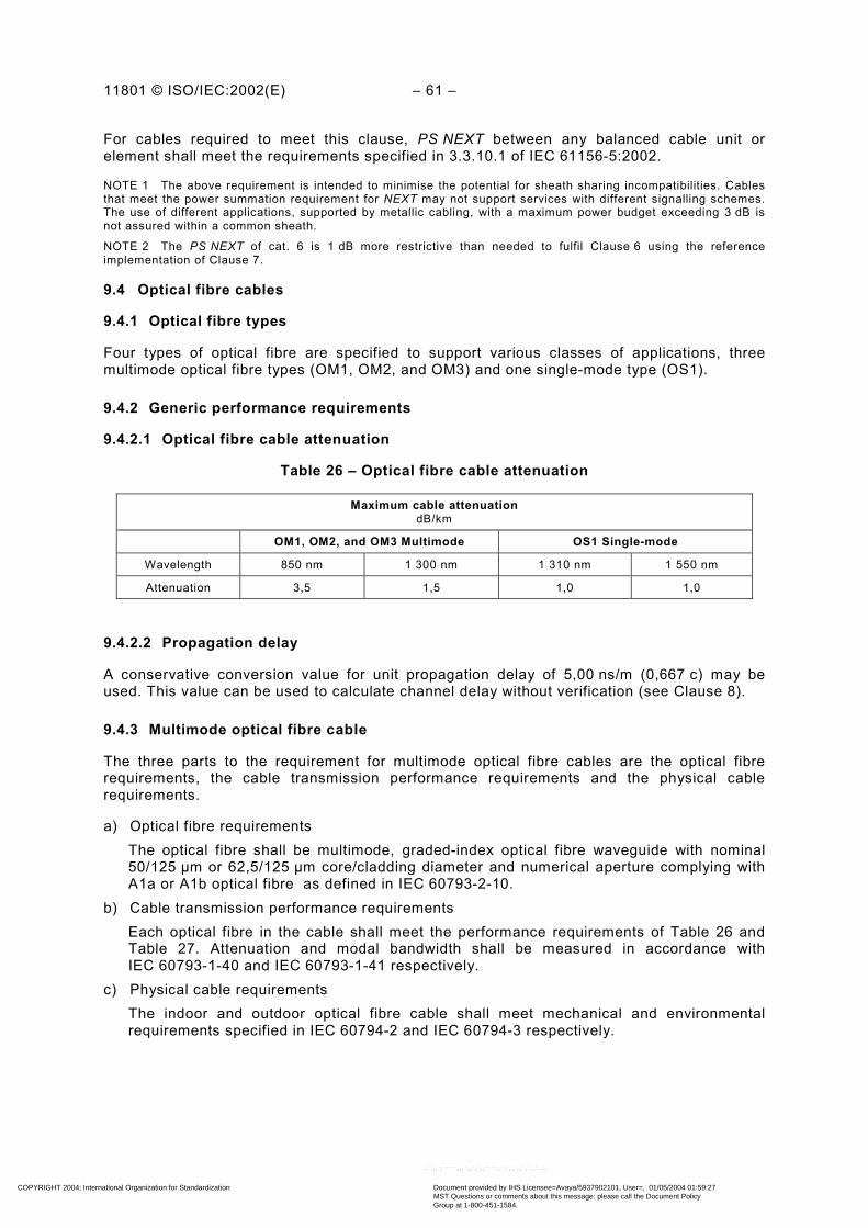
11801 © ISO/IEC:2002(E) – 61 –
For cables required to meet this clause, PS NEXT between any balanced cable unit orelement shall meet the requirements specified in 3.3.10.1 of IEC 61156-5:2002.
NOTE 1 The above requirement is intended to minimise the potential for sheath sharing incompatibilities. Cablesthat meet the power summation requirement for NEXT may not support services with different signalling schemes.The use of different applications, supported by metallic cabling, with a maximum power budget exceeding 3 dB isnot assured within a common sheath.
NOTE 2 The PS NEXT of cat. 6 is 1 dB more restrictive than needed to fulfil Clause 6 using the referenceimplementation of Clause 7.
9.4 Optical fibre cables
9.4.1 Optical fibre types
Four types of optical fibre are specified to support various classes of applications, threemultimode optical fibre types (OM1, OM2, and OM3) and one single-mode type (OS1).
9.4.2 Generic performance requirements
9.4.2.1 Optical fibre cable attenuation
Table 26 – Optical fibre cable attenuation
Maximum cable attenuationdB/km
OM1, OM2, and OM3 Multimode OS1 Single-mode
Wavelength 850 nm 1 300 nm 1 310 nm 1 550 nm
Attenuation 3,5 1,5 1,0 1,0
9.4.2.2 Propagation delay
A conservative conversion value for unit propagation delay of 5,00 ns/m (0,667 c) may beused. This value can be used to calculate channel delay without verification (see Clause 8).
9.4.3 Multimode optical fibre cable
The three parts to the requirement for multimode optical fibre cables are the optical fibrerequirements, the cable transmission performance requirements and the physical cablerequirements.
a) Optical fibre requirementsThe optical fibre shall be multimode, graded-index optical fibre waveguide with nominal50/125 µm or 62,5/125 µm core/cladding diameter and numerical aperture complying withA1a or A1b optical fibre as defined in IEC 60793-2-10.
b) Cable transmission performance requirementsEach optical fibre in the cable shall meet the performance requirements of Table 26 andTable 27. Attenuation and modal bandwidth shall be measured in accordance withIEC 60793-1-40 and IEC 60793-1-41 respectively.
c) Physical cable requirementsThe indoor and outdoor optical fibre cable shall meet mechanical and environmentalrequirements specified in IEC 60794-2 and IEC 60794-3 respectively.
COPYRIGHT 2004; International Organization for Standardization
Document provided by IHS Licensee=Avaya/5937902101, User=, 01/05/2004 01:59:27MST Questions or comments about this message: please call the Document PolicyGroup at 1-800-451-1584.
--``,,`,`````,,,`,,`,`,,````,-`-`,,`,,`,`,,`---

– 62 – 11801 © ISO/IEC:2002(E)
Table 27 – Multimode optical fibre modal bandwidth
Minimum modal bandwidthMHz × km
Overfilled launch bandwidth Effective laser launch bandwidth
Wavelength 850 nm 1 300 nm 850 nm
Optical fibre type Core diameterµm
OM1 50 or 62,5 200 500 Not specified
OM2 50 or 62,5 500 500 Not specified
OM3 50 1 500 500 2 000
NOTE Effective laser launch bandwidth is assured using differential mode delay (DMD) as specified inIEC/PAS 60793-1-49. Optical fibres that meet only the overfilled launch modal bandwidth may not support someapplications specified in Annex F.
9.4.4 Single-mode optical fibre cables
The three parts to the requirement for single-mode optical fibre cables are the optical fibrerequirements, the cable transmission performance and the physical cable requirements.
a) Optical fibre requirementsthe optical fibre shall comply with IEC 60793-2-50 type B1 and ITU-T G.652.
b) Cable transmission performance requirement1) Attenuation
each single-mode optical fibre in the cable shall have an attenuation in accordancewith Table 26. Attenuation shall be measured in accordance with IEC 60793-1-40.
2) Cut-off wavelengththe cut-off wavelength of cabled single-mode optical fibre shall be less than 1 260 nmwhen measured in accordance with IEC 60793-1-44.
c) Physical cable requirementsthe indoor and outdoor optical fibre cable shall meet mechanical and environmentalrequirements from IEC 60794-2 and IEC 60794-3 respectively.
10 Connecting hardware requirements
10.1 General requirements
10.1.1 Applicability
This clause provides guidelines and requirements for connecting hardware used in genericcabling. For the purpose of this clause, a connector is a component normally attached to acable or mounted on a piece of apparatus (excluding an adapter) for joining separable parts ofa cabling system. Unless otherwise specified, this standard specifies the minimumperformance of mated connectors as part of a link or channel. The requirements used in thisclause apply to mated connections. The requirements of the detail specifications for plugs andsockets referenced in this clause shall also be met.
These requirements apply to individual connectors which include telecommunications outlets,patch panels, consolidation point connectors, splices and cross-connects. All requirements forthese components are applicable for the temperature range of –10 °C to +60 °C. Performancerequirements do not include the effects of cross-connect jumpers or patch cords.Requirements for balanced cords are provided in Clause 13.
COPYRIGHT 2004; International Organization for Standardization
Document provided by IHS Licensee=Avaya/5937902101, User=, 01/05/2004 01:59:27MST Questions or comments about this message: please call the Document PolicyGroup at 1-800-451-1584.
--``,,`,`````,,,`,,`,`,,````,-`-`,,`,,`,`,,`---

11801 © ISO/IEC:2002(E) – 63 –
NOTE This clause does not address requirements for devices with passive or active electronic circuitry, includingthose whose main purpose is to serve a specific application or to provide compliance with other rules andregulations. Examples include media adapters, impedance matching transformers, terminating resistors, LANequipment, filters and protection apparatus. Such devices are considered to be outside the scope of genericcabling and may have significant detrimental effects on network performance. Therefore, it is important that theircompatibility with the cabling system and equipment be considered before use.
10.1.2 Location
Connecting hardware is installed:
a) in a campus distributor permitting connections to building backbone and campusbackbone cabling and equipment (if provided);
b) in a building distributor permitting connections to the backbone cabling and equipment (ifprovided);
c) in a floor distributor providing the cross-connections between backbone and horizontalcabling and permitting connections to equipment (if provided);
d) at the horizontal cabling consolidation point (if provided);e) at the telecommunications outlet;f) in the building entrance facility.
10.1.3 Design
In addition to its primary purpose, connecting hardware should be designed to provide
a) a means to identify cabling for installation and administration as described in Clause 12,b) a means to permit orderly cable management,c) a means of access to monitor or test cabling and equipment,d) protection against physical damage and ingress of contaminants,e) a termination density that is space efficient, but that also provides ease of cable
management and ongoing administration of the cabling system,f) a means to accommodate screening and bonding requirements, when applicable.
10.1.4 Operating environment
Performance of the connecting hardware shall be maintained over temperatures ranging from–10 °C to +60 °C. Connecting hardware should be protected from physical damage and fromdirect exposure to moisture and other corrosive elements. This protection may beaccomplished by installation indoors or in an appropriate enclosure for the environmentaccording to the relevant IEC standard.
10.1.5 Mounting
Connecting hardware should be designed to provide flexibility for mounting, either directly orby means of an adapter plate or enclosure. (For example, connecting hardware should havemounting provisions for placement on walls, in walls, in racks, or on other types of distributionframes and mounting fixtures.)
10.1.6 Installation practices
The manner and care with which the cabling is implemented are significant factors in theperformance and ease of administration of installed cabling systems. Installation and cablemanagement precautions should include the elimination of cable stress as caused by tension,sharp bends and tightly bunched cables.
COPYRIGHT 2004; International Organization for Standardization
Document provided by IHS Licensee=Avaya/5937902101, User=, 01/05/2004 01:59:27MST Questions or comments about this message: please call the Document PolicyGroup at 1-800-451-1584.
--``,,`,`````,,,`,,`,`,,````,-`-`,,`,,`,`,,`---

– 64 – 11801 © ISO/IEC:2002(E)
The connecting hardware shall be installed to permit
a) minimal signal impairment and maximum screen effectiveness (where screened cabling isused) by proper cable preparation, termination practices (in accordance withmanufacturer's guidelines) and well organised cable management,
b) room for mounting telecommunications equipment associated with the cabling system.Racks should have adequate clearances for access and cable dressing space.
The connecting hardware shall be identified according to the requirements of ISO/IEC 14763-1.Planning and installation of connecting hardware should be carried out in accordance withISO/IEC TR 14763-2.
NOTE 1 See ISO/IEC 18010 for information on pathways and spaces for customer premises cabling.
NOTE 2 Some connections are used to perform a crossover function between two elements to properly configurecabling links for transmit and receive connections.
NOTE 3 Improper termination of any balanced cable element or screen may degrade transmission performance,increase emissions and reduce immunity.
10.1.7 Marking and colour coding
In order to maintain consistent and correct point-to-point connections, provisions shall bemade to ensure that terminations are properly located with respect to connector positions andtheir corresponding cable elements. Such provisions may include the use of colours,alphanumeric identifiers or other means designed to ensure that cables are connected in aconsistent manner throughout the system.
When two physically similar cabling types are used in the same subsystem, they shall bemarked in such a way as to allow each cabling type to be clearly identified. For example,different performance categories, different nominal impedance and different optical fibre corediameters should carry unique markings or colours to facilitate visual identification.
10.2 Connecting hardware for balanced cabling
10.2.1 General requirements
The following requirements apply to all connecting hardware used to provide electricalconnections with balanced cables that comply with the requirements of Clause 9. It isdesirable that hardware used to directly terminate balanced cable elements be of theinsulation displacement connection (IDC) type. In addition to these requirements, connectinghardware used with screened cabling shall be in full compliance with Clause 11.
10.2.2 Performance marking
Connecting hardware intended for use with balanced cabling should be marked to designatetransmission performance at the discretion of the manufacturer. The markings, if any, shall bevisible during installation and do not replace other markings specified in 10.1.7, or inClause 12, or those required by local codes or regulations.
10.2.3 Mechanical characteristics
Connecting hardware intended for use with balanced cabling shall meet the requirementsspecified in Table 28.
COPYRIGHT 2004; International Organization for Standardization
Document provided by IHS Licensee=Avaya/5937902101, User=, 01/05/2004 01:59:27MST Questions or comments about this message: please call the Document PolicyGroup at 1-800-451-1584.
--``,,`,`````,,,`,,`,`,,````,-`-`,,`,,`,`,,`---

11801 © ISO/IEC:2002(E) – 65 –
Table 28 – Mechanical characteristics of connecting hardware for usewith balanced cabling
Mechanical characteristics Requirement Component or teststandard
Category 5 unscreened Mating dimensions and gauging IEC 60603-7-2 i
Category 5 screened Mating dimensions and gauging IEC 60603-7-3 k
Category 6 unscreened Mating dimensions and gauging IEC 60603-7-4 m
Category 6 screened Mating dimensions and gauging IEC 60603-7-5 na)
Physical dimensions(only attelecommunicationsoutlet)
Category 7 Mating dimensions and gauging IEC 60603-7-7 o
Cable termination compatibilityNominal conductor diameter – mm 0,5 to 0,65 a –
Patching d Stranded conductors –Jumpers Stranded or solid conductors –Cable typeOther Solid conductors –Categories 5 and 6 0,7 to 1,4 b, cNominal diameter of
insulated conductormm Category 7 0,7 to 1,6 –
Telecommunicationsoutlet 8Number of
conductors Other ≥2 × n (n = 1, 2, 3, ...)Visual inspection
Outlet ≤20Cable outer diametermm Plug ≤9 e
–
b)
Means to connect screen f Mechanical and environmentalperformance Annex C and Clause 11
Mechanical operation (durability)
Non-reusable IDC 1 IEC 60352-3 orIEC 60352-4
Reusable IDC ≥20 IEC 60352-3 orIEC 60352-4
Cable termination(cycles)
Non-reusable IPC 1 IEC 60352-6
Jumper termination (cycles) ≥200 g IEC 60352-3 orIEC 60352-4
TO-type interface (cycles) ≥750 hIEC 60603-7(unscreened) orIEC 60603-7-1 screened
c)
Other connections ≥200 h Annex Ca It is not required that connecting hardware be compatible with cables outside of this range. However, when
cables with conductor diameters as low as 0,4 mm or as high as 0,8 mm are used, special care shall be takento ensure compatibility with connecting hardware to which they connect.
b Use of the modular plug connector specified in series IEC 60603-7 is typically limited to cables havinginsulated conductor diameters in the range of 0,8 mm to 1,0 mm.
c It is not required that connecting hardware be compatible with cables outside of this range. However, whencables with insulated conductor diameters as high as 1,6 mm are used, special care shall be taken to ensurecompatibility with connecting hardware to which they connect.
d Connectors used in work area cords and equipment cords shall also be compatible with stranded conductors.e Applicable only to individual cable units.f If it is intended to use screened cabling, care should be taken that the connector is designed to terminate the
screen. There may be a difference between connectors designed to terminate balanced cables with overallscreens only, as opposed to cables having both individually screened elements and an overall screen (seeAnnex E).
g This durability requirement is only applicable to connections designed to administer cabling system changes(i.e., at a distributor).
h Mating and unmating under load is f.f.s.i At the time of publication IEC 60603-7-2 (Connectors for electronic equipment – Part 7-2: Detail specification
for 8-way, unshielded, free and fixed connectors, for data transmissions with frequencies up to 100 MHz) wasnot available. Until this specification is available compliance to requirements that refer to IEC 60603-7-2 maybe attained by full compliance with IEC 60603-7, combined with all applicable requirements of Clause 10 ofthis standard.
k At the time of publication IEC 60603-7-3 (Connectors for electronic equipment – Part 7-3: Detail specificationfor 8-way, shielded, free and fixed connectors, for data transmissions with frequencies up to 100 MHz) was notavailable. Until this specification is available compliance to requirements that refer to IEC 60603-7-3 may beattained by full compliance with IEC 60603-7-1, combined with all applicable requirements of Clause 10 of thisstandard.
m At the time of publication IEC 60603-7-4 (Connectors for electronic equipment – Part 7-4: Detail specificationfor 8-way, unshielded, free and fixed connectors, for data transmissions with frequencies up to 250 MHz) wasnot available. Until this specification is available compliance to requirements that refer to IEC 60603-7-4 maybe attained by full compliance with IEC 60603-7, combined with all applicable requirements of Clause 10 ofthis standard.
COPYRIGHT 2004; International Organization for Standardization
Document provided by IHS Licensee=Avaya/5937902101, User=, 01/05/2004 01:59:27MST Questions or comments about this message: please call the Document PolicyGroup at 1-800-451-1584.
--``,,`,`````,,,`,,`,`,,````,-`-`,,`,,`,`,,`---
– 66 – 11801 © ISO/IEC:2002(E)
n At the time of publication IEC 60603-7-5 (Connectors for electronic equipment – Part 7-5: Detail specificationfor 8-way, shielded, free and fixed connectors, for data transmissions with frequencies up to 250 MHz) was notavailable. Until this specification is available compliance to requirements that refer to IEC 60603-7-5 may beattained by full compliance with IEC 60603-7-1, combined with all applicable requirements of Clause 10 of thisstandard.
o In installations where other factors, such as HEM (see ISO/IEC 15018) applications, take preference overbackward compatibility offered with IEC 60603-7-7, the interface specified in IEC/PAS 61076-3-104/Ed.1 mayalso be used.
10.2.4 Electrical characteristics
10.2.4.1 General
Connecting hardware intended for use with balanced cabling shall meet the followingperformance requirements. Connecting hardware shall be tested with terminations and testleads that match the nominal characteristic impedance of the type of cables (i.e., 100 Ω or120 Ω) they are intended to support.
In the following tables, requirements are provided for a range of frequencies. Performancevalues at discrete frequencies are provided for reference only.
10.2.4.2 Telecommunications outlets
Telecommunications outlets of a given category shall meet the corresponding performancerequirements provided in Table 29. In addition, connectors in all other locations having thesame type of interface as the telecommunications outlet shall also comply with one or more ofthe standards specified in Table 29 with pair groupings as specified in 0. Requirements of10.2.4.3 shall be met for all TOs.
COPYRIGHT 2004; International Organization for Standardization
Document provided by IHS Licensee=Avaya/5937902101, User=, 01/05/2004 01:59:27MST Questions or comments about this message: please call the Document PolicyGroup at 1-800-451-1584.
--``,,`,`````,,,`,,`,`,,````,-`-`,,`,,`,`,,`---
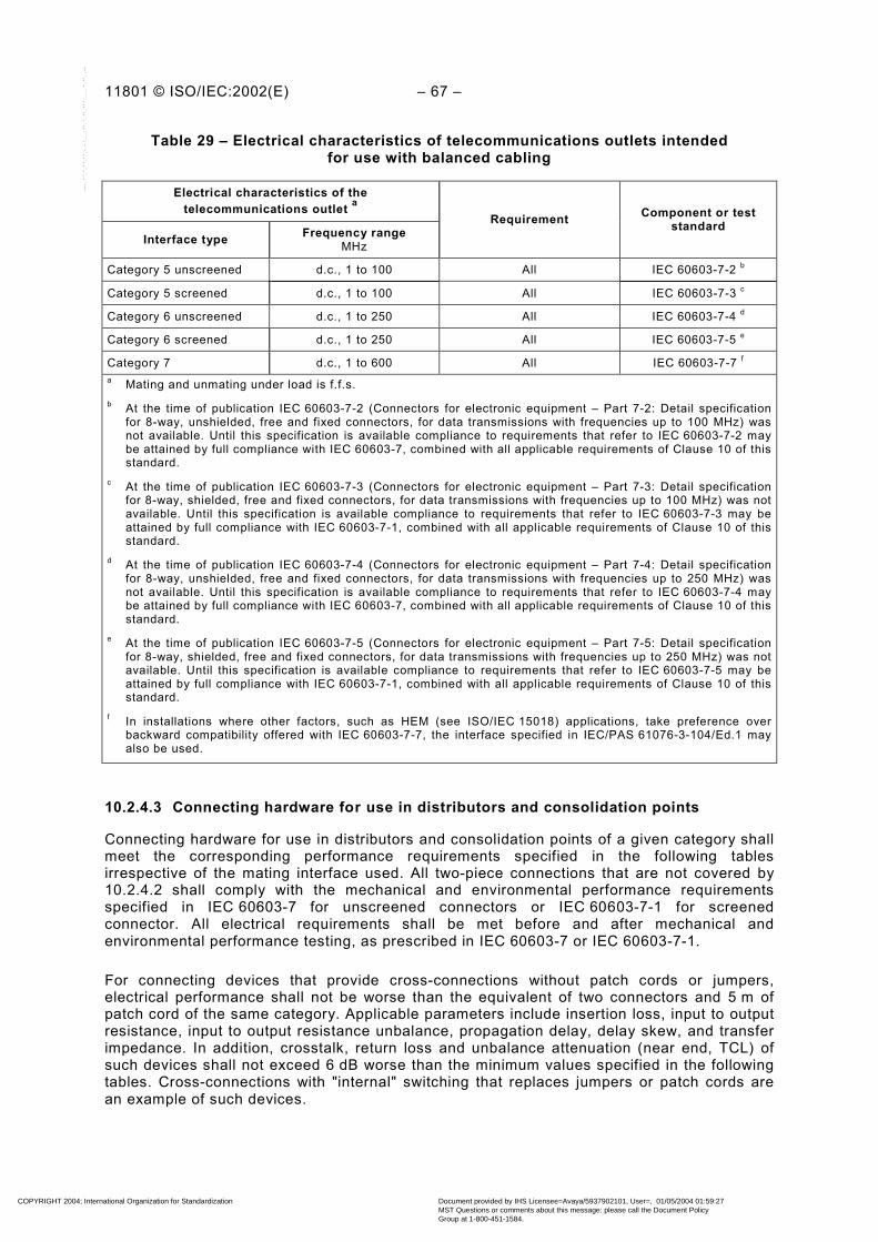
11801 © ISO/IEC:2002(E) – 67 –
Table 29 – Electrical characteristics of telecommunications outlets intendedfor use with balanced cabling
Electrical characteristics of thetelecommunications outlet a
Interface type Frequency rangeMHz
Requirement Component or teststandard
Category 5 unscreened d.c., 1 to 100 All IEC 60603-7-2 b
Category 5 screened d.c., 1 to 100 All IEC 60603-7-3 c
Category 6 unscreened d.c., 1 to 250 All IEC 60603-7-4 d
Category 6 screened d.c., 1 to 250 All IEC 60603-7-5 e
Category 7 d.c., 1 to 600 All IEC 60603-7-7 f
a Mating and unmating under load is f.f.s.b At the time of publication IEC 60603-7-2 (Connectors for electronic equipment – Part 7-2: Detail specification
for 8-way, unshielded, free and fixed connectors, for data transmissions with frequencies up to 100 MHz) wasnot available. Until this specification is available compliance to requirements that refer to IEC 60603-7-2 maybe attained by full compliance with IEC 60603-7, combined with all applicable requirements of Clause 10 of thisstandard.
c At the time of publication IEC 60603-7-3 (Connectors for electronic equipment – Part 7-3: Detail specificationfor 8-way, shielded, free and fixed connectors, for data transmissions with frequencies up to 100 MHz) was notavailable. Until this specification is available compliance to requirements that refer to IEC 60603-7-3 may beattained by full compliance with IEC 60603-7-1, combined with all applicable requirements of Clause 10 of thisstandard.
d At the time of publication IEC 60603-7-4 (Connectors for electronic equipment – Part 7-4: Detail specificationfor 8-way, unshielded, free and fixed connectors, for data transmissions with frequencies up to 250 MHz) wasnot available. Until this specification is available compliance to requirements that refer to IEC 60603-7-4 maybe attained by full compliance with IEC 60603-7, combined with all applicable requirements of Clause 10 of thisstandard.
e At the time of publication IEC 60603-7-5 (Connectors for electronic equipment – Part 7-5: Detail specificationfor 8-way, shielded, free and fixed connectors, for data transmissions with frequencies up to 250 MHz) was notavailable. Until this specification is available compliance to requirements that refer to IEC 60603-7-5 may beattained by full compliance with IEC 60603-7-1, combined with all applicable requirements of Clause 10 of thisstandard.
f In installations where other factors, such as HEM (see ISO/IEC 15018) applications, take preference overbackward compatibility offered with IEC 60603-7-7, the interface specified in IEC/PAS 61076-3-104/Ed.1 mayalso be used.
10.2.4.3 Connecting hardware for use in distributors and consolidation points
Connecting hardware for use in distributors and consolidation points of a given category shallmeet the corresponding performance requirements specified in the following tablesirrespective of the mating interface used. All two-piece connections that are not covered by10.2.4.2 shall comply with the mechanical and environmental performance requirementsspecified in IEC 60603-7 for unscreened connectors or IEC 60603-7-1 for screenedconnector. All electrical requirements shall be met before and after mechanical andenvironmental performance testing, as prescribed in IEC 60603-7 or IEC 60603-7-1.
For connecting devices that provide cross-connections without patch cords or jumpers,electrical performance shall not be worse than the equivalent of two connectors and 5 m ofpatch cord of the same category. Applicable parameters include insertion loss, input to outputresistance, input to output resistance unbalance, propagation delay, delay skew, and transferimpedance. In addition, crosstalk, return loss and unbalance attenuation (near end, TCL) ofsuch devices shall not exceed 6 dB worse than the minimum values specified in the followingtables. Cross-connections with "internal" switching that replaces jumpers or patch cords arean example of such devices.
COPYRIGHT 2004; International Organization for Standardization
Document provided by IHS Licensee=Avaya/5937902101, User=, 01/05/2004 01:59:27MST Questions or comments about this message: please call the Document PolicyGroup at 1-800-451-1584.
--``,,`,`````,,,`,,`,`,,````,-`-`,,`,,`,`,,`---

– 68 – 11801 © ISO/IEC:2002(E)
Table 30 – Return loss
Requirement
Connector categoryElectrical characteristics FrequencyMHz
5 6 7
Test standard
1 to 100 60 – 20 lg(f) – –
1 to 250 – 64 – 20 lg(f) –Minimum return loss a
dB1 to 600 – – 68 – 20 lg(f)
1 30,0 30,0 30,0
100 20,0 24,0 28,0
250 N/A 16,0 20,0
Minimum return loss at keyfrequenciesdB
600 N/A N/A 12,4
IEC 60512-25-5
a Return loss at frequencies that correspond to calculated values of greater than 30,0 dB shall revert to aminimum requirement of 30,0 dB.
Table 31 – Insertion loss
Requirement
Connector categoryElectrical characteristics FrequencyMHz
5 6 7
Test standard
1 to 100 f04,0 – –
1 to 250 – f02,0 –Maximum insertion loss a
dB
1 to 600 – – f02,0
1 0,10 0,10 0,10
100 0,40 0,20 0,20
250 N/A 0,32 0,32
Maximum insertion loss atkey frequenciesdB
600 N/A N/A 0,49
IEC 60512-25-2
a Insertion loss at frequencies that correspond to calculated values of less than 0,1 dB shall revert to arequirement of 0,1 dB maximum.
Table 32 – Near end crosstalk (NEXT)
Requirement
Connector categoryElectrical characteristics FrequencyMHz
5 6 7
Test standard
1 to 100 83 – 20 lg (f) – –
1 to 250 – 94 – 20 lg (f) –Minimum near endcrosstalk (NEXT) a
dB1 to 600 – – 102,4 – 15 lg (f)
1 80,0 80,0 80,0
100 43,0 54,0 72,4
250 N/A 46,0 66,4
Minimum NEXT at keyfrequenciesdB
600 N/A N/A 60,7
IEC 60512-25-1
a NEXT at frequencies that correspond to calculated values of greater than 80,0 dB shall revert to a minimumrequirement of 80,0 dB.
COPYRIGHT 2004; International Organization for Standardization
Document provided by IHS Licensee=Avaya/5937902101, User=, 01/05/2004 01:59:27MST Questions or comments about this message: please call the Document PolicyGroup at 1-800-451-1584.
--``,,`,`````,,,`,,`,`,,````,-`-`,,`,,`,`,,`---

11801 © ISO/IEC:2002(E) – 69 –
Table 33 – Power sum near end crosstalk (PS NEXT)(for information only)
Requirement b
Connector categoryElectrical characteristics FrequencyMHz
5 6 7
Test standard
1 to 100 80 – 20 lg(f) – –
1 to 250 – 90 – 20 lg(f) –Minimum power sum nearend crosstalk (PS NEXT) a
dB1 to 600 – – 99,4 – 15 lg(f)
1 77,0 77,0 77,0
100 40,0 50,0 69,4
250 N/A 42,0 63,4
Minimum PS NEXT at keyfrequenciesdB
600 N/A N/A 57,7
IEC 60512-25-1
a PS NEXT at frequencies that correspond to calculated values of greater than 77,0 dB shall revert to aminimum requirement of 77,0 dB.
b Equations and values for power sum NEXT are provided for information only.
Table 34 – Far end crosstalk (FEXT)
Requirement
Connector categoryElectrical characteristics FrequencyMHz
5 6 7
Test standard
1 to 100 75,1 – 20 lg(f) – –
1 to 250 – 83,1 – 20 lg(f) –Minimum far end crosstalk(FEXT) a, b
dB1 to 600 – – 90 – 15 lg(f)
1 65,0 65,0 65,0
100 35,1 43,1 60,0
250 N/A 35,1 54,0
Minimum FEXT at keyfrequenciesdB
600 N/A N/A 48,3
IEC 60512-25-1
a FEXT at frequencies that correspond to calculated values of greater than 65,0 dB shall revert to a minimumrequirement of 65,0 dB.
b For connectors, the difference between FEXT and ELFEXT is minimal. Therefore, connector FEXTrequirements are used to model ELFEXT performance for links and channels.
COPYRIGHT 2004; International Organization for Standardization
Document provided by IHS Licensee=Avaya/5937902101, User=, 01/05/2004 01:59:27MST Questions or comments about this message: please call the Document PolicyGroup at 1-800-451-1584.
--``,,`,`````,,,`,,`,`,,````,-`-`,,`,,`,`,,`---
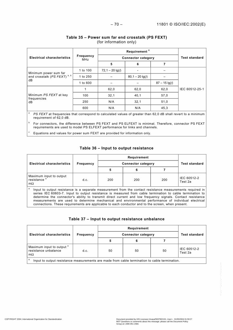
– 70 – 11801 © ISO/IEC:2002(E)
Table 35 – Power sum far end crosstalk (PS FEXT)(for information only)
Requirement c
Connector categoryElectrical characteristics FrequencyMHz
5 6 7
Test standard
1 to 100 72,1 – 20 lg(f) - –
1 to 250 – 80,1 – 20 lg(f) –Minimum power sum farend crosstalk (PS FEXT) a, b
dB1 to 600 – – 87 – 15 lg(f)
1 62,0 62,0 62,0
100 32,1 40,1 57,0
250 N/A 32,1 51,0
Minimum PS FEXT at keyfrequenciesdB
600 N/A N/A 45,3
IEC 60512-25-1
a PS FEXT at frequencies that correspond to calculated values of greater than 62,0 dB shall revert to a minimumrequirement of 62,0 dB.
b For connectors, the difference between PS FEXT and PS ELFEXT is minimal. Therefore, connector PS FEXTrequirements are used to model PS ELFEXT performance for links and channels.
c Equations and values for power sum FEXT are provided for information only.
Table 36 – Input to output resistance
Requirement
Connector categoryElectrical characteristics Frequency
5 6 7
Test standard
Maximum input to outputresistance a
mΩd.c. 200 200 200 IEC 60512-2
Test 2a
a Input to output resistance is a separate measurement from the contact resistance measurements required inseries IEC 60603-7. Input to output resistance is measured from cable termination to cable termination todetermine the connector's ability to transmit direct current and low frequency signals. Contact resistancemeasurements are used to determine mechanical and environmental performance of individual electricalconnections. These requirements are applicable to each conductor and to the screen, when present.
Table 37 – Input to output resistance unbalance
Requirement
Connector categoryElectrical characteristics Frequency
5 6 7
Test standard
Maximum input to output a
resistance unbalancemΩ
d.c. 50 50 50 IEC 60512-2Test 2a
a Input to output resistance measurements are made from cable termination to cable termination.
COPYRIGHT 2004; International Organization for Standardization
Document provided by IHS Licensee=Avaya/5937902101, User=, 01/05/2004 01:59:27MST Questions or comments about this message: please call the Document PolicyGroup at 1-800-451-1584.
--``,,`,`````,,,`,,`,`,,````,-`-`,,`,,`,`,,`---

11801 © ISO/IEC:2002(E) – 71 –
Table 38 – Current carrying capacity
Requirement
Connector categoryElectrical characteristics Frequency
5 6 7
Test standard
Minimum current carryingcapacity a, b, c
Ad.c. 0,75 0,75 0,75 IEC 60512-3
Test 5b
a Applicable for an ambient temperature of 60 °C.b Sample preparation shall be as specified in IEC 60603-7 (unscreened) or IEC 60603-7-1 (screened).c Applicable to each conductor including the screen, if present.
Table 39 – Propagation delay
Requirement
Connector categoryElectrical characteristics FrequencyMHz
5 6 7
Test standard
1 to 100 2,5 – –
1 to 250 – 2,5 –Maximum propagationdelayns
1 to 600 – – 2,5
IEC 60512-25-4
Table 40 – Delay skew
Requirement
Connector categoryElectrical characteristics FrequencyMHz
5 6 7
Test standard
1 to 100 1,25 – –
1 to 250 – 1,25 –Maximum delay skewns
1 to 600 – – 1,25
IEC 60512-25-4
Table 41 – Transverse conversion loss (TCL) f.f.s.
Requirement
Connector categoryElectrical characteristics FrequencyMHz
5 6 7
Test standard
1 to 100 66 – 20 lg(f) – –
1 to 250 – 66 – 20 lg(f) –Minimum transverseconversion loss (TCL) a
dB1 to 600 – – 66 – 20 lg(f) b
1 60,0 60,0 60,0
100 26,0 26,0 26,0
250 N/A 18,0 18,0
Minimum TCL at keyfrequenciesdB
600 N/A N/A f.f.s.
IEC 60603-7-7,Annex K
a TCL at frequencies that correspond to calculated values of greater than 60,0 dB shall revert to a minimumrequirement of 60,0 dB.
b The applicability of this equation and test standard at frequencies above 250 MHz is f.f.s.
COPYRIGHT 2004; International Organization for Standardization
Document provided by IHS Licensee=Avaya/5937902101, User=, 01/05/2004 01:59:27MST Questions or comments about this message: please call the Document PolicyGroup at 1-800-451-1584.
--``,,`,`````,,,`,,`,`,,````,-`-`,,`,,`,`,,`---
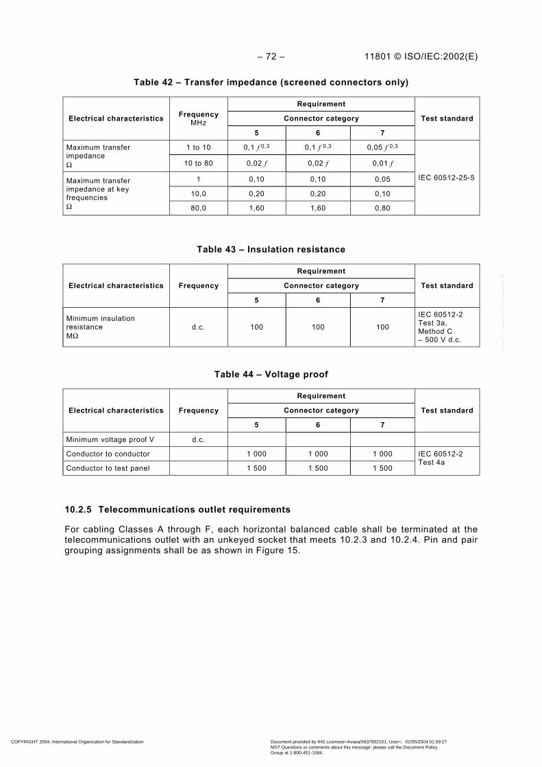
– 72 – 11801 © ISO/IEC:2002(E)
Table 42 – Transfer impedance (screened connectors only)
Requirement
Connector categoryElectrical characteristics FrequencyMHz
5 6 7
Test standard
1 to 10 0,1 f 0,3 0,1 f 0,3 0,05 f 0,3Maximum transferimpedanceΩ 10 to 80 0,02 f 0,02 f 0,01 f
1 0,10 0,10 0,05
10,0 0,20 0,20 0,10
Maximum transferimpedance at keyfrequenciesΩ 80,0 1,60 1,60 0,80
IEC 60512-25-5
Table 43 – Insulation resistance
Requirement
Connector categoryElectrical characteristics Frequency
5 6 7
Test standard
Minimum insulationresistanceMΩ
d.c. 100 100 100
IEC 60512-2Test 3a,Method C– 500 V d.c.
Table 44 – Voltage proof
Requirement
Connector categoryElectrical characteristics Frequency
5 6 7
Test standard
Minimum voltage proof V d.c.
Conductor to conductor 1 000 1 000 1 000
Conductor to test panel 1 500 1 500 1 500
IEC 60512-2Test 4a
10.2.5 Telecommunications outlet requirements
For cabling Classes A through F, each horizontal balanced cable shall be terminated at thetelecommunications outlet with an unkeyed socket that meets 10.2.3 and 10.2.4. Pin and pairgrouping assignments shall be as shown in Figure 15.
COPYRIGHT 2004; International Organization for Standardization
Document provided by IHS Licensee=Avaya/5937902101, User=, 01/05/2004 01:59:27MST Questions or comments about this message: please call the Document PolicyGroup at 1-800-451-1584.
--``,,`,`````,,,`,,`,`,,````,-`-`,,`,,`,`,,`---

11801 © ISO/IEC:2002(E) – 73 –
1 2 3 4 5 6 7 8
OUTLET POSITIONS
NOTE - For class F, there is no need to configure pairs onpins 3, 6 & 4, 5 as shown.
Figure 15 – Eight-position outlet pin and pair grouping assignments(front view of connector)
If different interfaces are used at the distributor, CP or TO in the same link or channel, thecabling connections shall be configured with consistent pin/pair assignments to ensure end-to-end connectivity. Pair rearrangement at the telecommunications outlet should not involvemodification of the horizontal cable terminations. If pair rearrangement is used at thetelecommunications outlet, the configuration of the outlet terminations shall be clearlyidentified.
Plugs and sockets that are intermateable shall be backward compatible with those of differentperformance categories. Backward compatibility means that mated connections with plugsand sockets from different categories shall meet all requirements for the lower categorycomponent. See Table 45 for a matrix of mated modular connector performance that isrepresentative of backward compatible connectivity.
Table 45 – Matrix of backward compatible mated modular connector performance
Category of modular connector (TO)performance
Category 5 Category 6 Category 7
Category 5 Category 5 Category 5 Category 5
Category 6 Category 5 Category 6 Category 6
Category 7 Category 5 Category 6 Category 7
NOTE 1 When two physically similar cabling links are used in the same installation, special precautions arerequired to ensure that they are properly identified at the telecommunications outlet. Examples of when suchidentification is necessary would include different performance classes or cables with different nominal impedance.See Clause 12.
NOTE 2 For proper connectivity, care is needed to ensure that pairs are terminated consistently at thetelecommunications outlet and floor distributor. If pairs are terminated on different positions at the two ends of alink, although DC continuity may be maintained, through connectivity will be lost. See Clause 12 for cabling systemadministration.
10.2.6 Design considerations for installation
Connecting hardware should be designed in such a way that the untwisted length in a cableelement, resulting from its termination to connecting hardware is as short as possible.
Mod
ular
Plu
g&
Cor
dP
erfo
rman
ce
COPYRIGHT 2004; International Organization for Standardization
Document provided by IHS Licensee=Avaya/5937902101, User=, 01/05/2004 01:59:27MST Questions or comments about this message: please call the Document PolicyGroup at 1-800-451-1584.
--``,,`,`````,,,`,,`,`,,````,-`-`,,`,,`,`,,`---

– 74 – 11801 © ISO/IEC:2002(E)
Connecting hardware should permit a minimum length of exposed pairs between the end ofthe cable sheath and the point of termination. In addition, only the length of cable sheathrequired for termination and trimming should be removed or stripped back. Theserecommendations are provided to minimise the impact of terminations on transmissionperformance and are not intended to constrain twist length for cable or jumper construction.
Earthing requirements and screen continuity considerations are specified in Clause 11.
10.3 Optical fibre connecting hardware
10.3.1 General requirements
The requirements of 10.3.2 through 10.3.5 apply to all connecting hardware used to provideconnections between optical fibre cables described in Clause 9 with the following exception.The requirements of 10.3.4 and Table 46, item a) apply to the telecommunications outlet only.
NOTE Fibre adapters and connectors should be protected from dust and other contaminants while they are in anunmated state. It is also recommended to clean fibre end-faces prior to connection.
10.3.2 Marking and colour coding
Correct coding of connectors and adapters, for example by colour, should be used to ensurethat mating of different optical fibre types does not occur. In addition, keying and theidentification of optical fibre positions may be used to ensure that correct polarity ismaintained for duplex links.
The connectors and adapters should be coloured to distinguish between single-mode andmultimode optical fibres. Additional colours or labels may be required to distinguish betweenthe multimode optical fibre types.
NOTE 1 These markings are in addition to, and do not replace, other markings specified in Clause 12, or thoserequired by local codes or regulations.
NOTE 2 The following colour codes apply to IEC 60874-19-1 SC duplex and IEC 60874-14 SC simplex connectorsbut may also be used for other connector types:
Multimode 50 µm and 62,5 µm: Beige or black
Single-mode PC: BlueSingle-mode APC: Green
10.3.3 Mechanical and optical characteristics
Optical fibre connecting hardware shall meet the requirements of Table 46. All connectionsnot covered by 10.3.4 shall comply with at least the equivalent optical, mechanical andenvironmental performance requirements specified in IEC 60874-19-1.
COPYRIGHT 2004; International Organization for Standardization
Document provided by IHS Licensee=Avaya/5937902101, User=, 01/05/2004 01:59:27MST Questions or comments about this message: please call the Document PolicyGroup at 1-800-451-1584.
--``,,`,`````,,,`,,`,`,,````,-`-`,,`,,`,`,,`---

11801 © ISO/IEC:2002(E) – 75 –
Table 46 – Mechanical and optical characteristics of optical fibre connecting hardware
Mechanical and optical characteristics Requirement Component or teststandard
a) Physical dimensions(only at telecommunications outlet) a, d
Mating dimensions andgauging
IEC 60874-19-3(multimode) orIEC 60874-19-2 (single-mode)
Cable termination compatibility
Nominal cladding diameterµm 125 IEC 60793-2, Clause 5
(A1a, A1b) and 32.2 (B1)
Nominal buffer diametermm – IEC 60794-2, 6.1
b)
Cable outer diametermm – IEC 60794-2, 6.1
c) Mechanical endurance (durability)cycles ≥500 IEC 61300-2-2
Mated pair transmission performance
Other 0,75 IEC 61300-3-34Maximum insertionloss b, c
dB Splice 0,3 IEC 61073-1
Multimode 20
d)
Minimum return lossdB Single-mode 35
IEC 61300-3-6
a See 10.3.4b As required in IEC 61753-1-1, Class M1.c Insertion loss values of connectors and splices shall be met with the referenced test method where the optical
source produces an overfilled launch condition (for example, an LED source). Measurements with an opticalsource that produces an underfilled launch condition (for example, a laser source) will always produce lowerinsertion loss values.
d The connectors used with the specified SC duplex adaptors shall meet the IEC 60874-14 (simplex) orIEC 60874-19 (duplex) series of detail specifications.
10.3.4 Telecommunications outlet requirements
The optical fibre cables in the work area shall be connected to the horizontal cabling at thetelecommunications outlet with a duplex SC-connector, (SC-D), that complies withIEC 60874-19-1.
The optical fibre connector used at the TO shall meet the requirements of 10.3.3.
10.3.5 Connection schemes for optical fibre cabling
10.3.5.1 General
Consistent polarity of duplex optical fibre connections shall be maintained throughout thecabling system by means of physical keying, administration (i.e., labelling) or both. Thefollowing guidelines are provided to ensure that properly installed connectors and adaptersprovide a functional and maintainable optical fibre cabling system. Consult with equipmentmanufacturers and system integrators to determine the suitability of these guidelines forspecific networking applications. Additionally, all optical ports should comply with IEC 60825.
To ensure maximum flexibility on the cabling side of TOs and distributor panels a simplexconnector is recommended for the termination of horizontal and backbone optical cables asillustrated in Figure 16.
COPYRIGHT 2004; International Organization for Standardization
Document provided by IHS Licensee=Avaya/5937902101, User=, 01/05/2004 01:59:27MST Questions or comments about this message: please call the Document PolicyGroup at 1-800-451-1584.
--``,,`,`````,,,`,,`,`,,````,-`-`,,`,,`,`,,`---

– 76 – 11801 © ISO/IEC:2002(E)
On the work area or patch side of TOs and distributor panels, a duplex presentation maintainsthe correct polarity of transmit and receive optical fibres in two optical fibre transmissionsystems while still allowing transmission systems using other optical fibre counts. At thedistributor, this presentation is preferably a duplex adapter that maintains the proper spacingand alignment as defined by IEC 60874-19-1 or other applicable IEC interface standards.
Polarity is defined at the TO by either keying, or labelling of the adapters as position A and B.To extend this polarity to the entire cabling system, it is important that the same keyingorientation, colour coding, marking, and optical fibre configuration be consistently applied.Once the system is installed and correct polarity is verified, the optical fibre cabling systemwill maintain the correct polarity of transmit and receive optical fibres.
10.3.5.2 Connectivity options at the TO
The connectors and adapters shall have their keys oriented as shown in Figure 16.
Figure 16 – Duplex SC connectivity configuration
10.3.5.3 Connectivity options at other locations
Polarity at locations other than the TO may be maintained by the strict control of changes tothe connectivity at distributors and CPs, or by adopting the configurations detailed in 10.3.5.2.Connectors at locations other than the TO shall meet the optical, mechanical, andenvironmental requirements stated in IEC 60874-19-1, although they may have other matinginterfaces.
10.3.5.4 Other duplex connectors
Alternate connector designs (for example SFF) shall employ similar labelling and identificationschemes to the duplex SC. Position A and B on alternate duplex connector designs shall be inthe same position as the IEC 60874-19-1 (SC duplex) in Figure 16. For alternate connectordesigns utilising latches, the latch defines the positioning in the same manner as the key andkeyways.
When high density is an important consideration for the building entrance facility, campusdistributor, building distributor, floor distributor, or consolidation point, then Small Form Factor(SFF) connector designs are recommended. When used, SFF connectors shall be covered byan approved IEC interface standard and shall satisfy the performance requirements of 10.3.3.
COPYRIGHT 2004; International Organization for Standardization
Document provided by IHS Licensee=Avaya/5937902101, User=, 01/05/2004 01:59:27MST Questions or comments about this message: please call the Document PolicyGroup at 1-800-451-1584.
--``,,`,`````,,,`,,`,`,,````,-`-`,,`,,`,`,,`---

11801 © ISO/IEC:2002(E) – 77 –
10.3.5.5 Patch cord termination configuration
It is recommended that connection of patch cords and equipment cords to the duplex adapterbe made by means of a duplex connector assembly.
Optical fibre patch cords, whether they are used for cross-connection or interconnection toequipment, shall be of a cross-over orientation such that Position A goes to Position B on oneoptical fibre, and Position B goes to Position A on the other optical fibre of the optical fibrepair (Figure 17). Each end of the optical fibre patch cord shall be identified to indicatePosition A and Position B if the connector can be separated into its simplex components. Foralternate connector designs utilising latches, the latch defines the positioning in the samemanner as the keys.
For simplex connectors, the connector that plugs into the receiver shall be consideredPosition A, and the connector that plugs into the transmitter shall be considered Position B.
Legend:
= Position “A”
= Position “B”
Figure 17 – Optical fibre patch cord
11 Screening practices
11.1 General
This clause applies when screened cables or cables with screened elements or units areused. Only basic guidance is provided. The procedures necessary to provide adequateearthing for both electrical safety and EM performance are subject to national and localregulations, always to proper workmanship in accordance with ISO/IEC TR 14763-2, and incertain cases to installation specific engineering. Some cabling employs components thatutilise screening for additional crosstalk performance and is therefore also subject toscreening practices. Note that a proper handling of screens in accordance withISO/IEC TR 14763-2 and suppliers’ instructions will increase performance and safety.
11.2 Electromagnetic performance
Cabling screens should be properly bonded to earth for electrical safety and to optimise EMperformance. All cabling components which form part of a screened channel should bescreened and meet the screening requirements given in Clauses 9 and 10. Screened cablinglinks shall meet cabling screening requirements given in 6.4. Cable screens shall beterminated to connector screens by low impedance terminations sufficient to maintain screencontinuity necessary to meet cabling screening requirements. Suppliers’ instructions as howto make low impedance terminations shall be asked for and observed. Work area, equipmentcords and the equipment attachment should be screened and if so, shall provide screencontinuity.
COPYRIGHT 2004; International Organization for Standardization
Document provided by IHS Licensee=Avaya/5937902101, User=, 01/05/2004 01:59:27MST Questions or comments about this message: please call the Document PolicyGroup at 1-800-451-1584.
--``,,`,`````,,,`,,`,`,,````,-`-`,,`,,`,`,,`---

– 78 – 11801 © ISO/IEC:2002(E)
11.3 Earthing
Earthing and bonding shall be in accordance with applicable electrical codes or IEC 60364-1.All screens of the cables shall be bonded at each distributor. Normally, the screens arebonded to the equipment racks, which are, in turn, bonded to building earth.
NOTE High working frequencies and/or high frequencies of parasitic currents or fields require earthing with lowimpedance, which may be realised with a meshed system.
The bond shall be designed to ensure that
a) The path to earth shall be permanent, continuous and of low impedance. It isrecommended that each equipment rack is individually bonded, in order to assure thecontinuity of the earth path.
b) The cable screens provide a continuous earth path to all parts of a cabling system that areinterconnected by it.
This bonding ensures that voltages that are induced into cabling (by any disturbances frompower lines or any other disturbers) are directed to building earth, and so do not causeinterference to the transmitted signals. All earthing electrodes to different systems in thebuilding shall be bonded together to reduce effects of differences in earth potential. Thebuilding earthing system should not exceed the earth potential difference limits of 1 V r.m.s.between any two earths on the network.
12 Administration
Administration is an essential aspect of generic cabling. The flexibility of generic cabling canbe fully exploited only if the cabling and its use is properly administered. Administrationinvolves accurate identification and record keeping of all the components that comprise thecabling system as well as the pathways, distributors and other spaces in which it is installed.All changes to the cabling should be recorded when they are carried out. Computer basedadministration of records is strongly recommended for larger installations.
Telecommunications cabling administration shall comply with ISO/IEC 14763-1.
13 Balanced cords
13.1 Introduction
This clause covers balanced cords constructed of two plugs as specified in the IEC 60603-7series and balanced cables as specified in the document series IEC 61156. The componentsused in these cords shall meet the requirements of Clauses 9 and 10. Their purpose is toconnect to connecting hardware that utilises sockets that are also defined in the IEC 60603-7series.
NOTE It is assumed that cords that use connectors with interfaces other than the IEC 60603-7 series also meetthe requirements of this clause.
Connecting hardware performance is subject to influence by the properties of the plugtermination and therefore cords should be tested to determine the quality of the assembly.This clause specifies the minimum requirements for cords. The test methods and mechanicalstresses are specified in IEC 61935-2. All requirements of this clause have to be met afterfirst exposing the device under test to the mechanical stress. Cords shall meet the electricaland mechanical requirements of IEC 61935-2.
13.2 Insertion loss
Insertion loss (IL) of cords shall not exceed the value stated for the given length. Theinsertion loss performance is achieved by design.
COPYRIGHT 2004; International Organization for Standardization
Document provided by IHS Licensee=Avaya/5937902101, User=, 01/05/2004 01:59:27MST Questions or comments about this message: please call the Document PolicyGroup at 1-800-451-1584.
--``,,`,`````,,,`,,`,`,,````,-`-`,,`,,`,`,,`---

11801 © ISO/IEC:2002(E) – 79 –
13.3 Return loss
Cords shall meet return loss (RL) requirements specified in Table 47. The cords shall meetthe electrical and mechanical properties of IEC 61935-2.
Table 47 – Minimum return loss for balanced cords
Return lossdB
FrequencyMHz
All Categories
1 ≤ f < 25 19,8 + 3 lg(f)
25 ≤ f ≤ 100/250/600 38,0 – 10 lg(f)
Table 48 – Informative values of return loss at key frequenciesfor Category 5, 6 and 7 cords
Return LossdBFrequency
MHzCategory 5 cord Category 6 cord Category 7 cord
1 19,8 19,8 19,8
16 23,4 23,4 23,4
100 18,0 18,0 18,0
250 N/A 14,0 14,0
600 N/A N/A 10,2
13.4 NEXT
The cords for Category 5, 6 and 7 shall meet the requirements calculated according toequations (6) to (10) when measured in accordance with IEC 61935-2.
RSXT
ILNEXTNEXT
NEXT +
⋅+−
+
−
−= 10connector2cable
1010connectors
10 lg10cord
(6)
whereNEXT cord is the NEXT of the entire cord in dBNEXT connectors is the NEXT of the connectors in dBNEXT cable is the NEXT of the cable itself in dBIL connector is the insertion loss of one connector in dBRSXT is the reflected signal cross talk
NOTE The value for “cord”, “connector” and “cable” is expressed in dB.
with
RSXT = 0 dB for category 5 cordsRSXT = 0,5 dB for category 6 and category 7 cords.
and
COPYRIGHT 2004; International Organization for Standardization
Document provided by IHS Licensee=Avaya/5937902101, User=, 01/05/2004 01:59:27MST Questions or comments about this message: please call the Document PolicyGroup at 1-800-451-1584.
--``,,`,`````,,,`,,`,`,,````,-`-`,,`,,`,`,,`---

– 80 – 11801 © ISO/IEC:2002(E)
++−
+
−
−=
20connectorcable2remote
1020local
10 lg 20connectors
ILILNEXTNEXT
NEXT(7)
The frequency dependence of NEXT, if the anchor value at 100 MHz is known, is given by:
−==100
lg 20)100(connectorremotelocalf
NEXTNEXTNEXT (8)
100m 100 cablecableLαIL ×≈ (9)
whereNEXT local is the NEXT of the connector at the local end of the cord in dBNEXT remote is the NEXT of the connector at the remote end of the cord in dBIL cable is the insertion loss of the cable in dBIL connector is the insertion loss of the connector in dBNEXT connector (100) is the NEXT of the connector in dB at 100 MHz
α cable 100 m is the insertion loss of 100 m of the cable used for the cordL is the length of the cable in the cord
The length corrected near-end crosstalk of the cable of the cord is given by:
5
m 100,cable
101
5
m 100,cable
100101lg10
m100,cableL,cable
α
αL
NEXTNEXT
−
−×−= (10)
Calculations yielding NEXT limits in excess of 65 dB shall revert to a limit of 65 dB. Table 49lists informative values of NEXT at key frequencies for different length of the cords.
COPYRIGHT 2004; International Organization for Standardization
Document provided by IHS Licensee=Avaya/5937902101, User=, 01/05/2004 01:59:27MST Questions or comments about this message: please call the Document PolicyGroup at 1-800-451-1584.
--``,,`,`````,,,`,,`,`,,````,-`-`,,`,,`,`,,`---

11801 © ISO/IEC:2002(E) – 81 –
Table 49 – Informative values of NEXT at key frequenciesfor Category 5, 6 and 7 cords
NEXTdB
Category 5 cord Category 6 cord Category 7 cord
Length Length Length
FrequencyMHz
2 m 5 m 10 m 2 m 5 m 10 m 2 m 5 m 10 m
1 65,0 65,0 65,0 65,0 65,0 65,0 65,0 65,0 65,0
16 50,3 49,5 48,7 61,6 60,0 58,5 65,0 65,0 65,0
100 35,0 34,7 34,5 46,2 45,0 44,2 65,0 65,0 65,0
250 38,6 37,9 37,6 60,7 61,2 61,9
600
N/A
N/A 55,4 56,2 57,0
For the commonly available Category 5 test head the anchor value at 100 MHz is:
( ) 0,41100connector =NEXT (11)
COPYRIGHT 2004; International Organization for Standardization
Document provided by IHS Licensee=Avaya/5937902101, User=, 01/05/2004 01:59:27MST Questions or comments about this message: please call the Document PolicyGroup at 1-800-451-1584.
--``,,`,`````,,,`,,`,`,,````,-`-`,,`,,`,`,,`---

– 82 – 11801 © ISO/IEC:2002(E)
Annex A (normative)
Balanced permanent link and CP link performance
A.1 General
This Annex contains performance requirement equations for balanced permanent links andCP links as shown in Figure A.1.
The cabling under test in configurations A, B and C is termed the permanent link. Theconfigurations A and B comprise fixed cabling only. Configuration C comprises fixed cablingand a CP cable between the CP and the TO. Measurements made for this configuration shallbe repeated if the CP cable is changed. The cabling under test in configuration D containsfixed cabling only and is termed the CP link.
In all configurations the test configuration reference plane of a permanent link or CP link iswithin the test cord. The test cord connection which mates with the termination point of thepermanent link or CP link under test is part of the link under test.
TOPP
CPC CPP
Tester C Configuration DTesterTO
C C
CP link
Horizontal cabling
TesterTOCP
C CPP
Tester C C C Configuration CHorizontal cabling
TesterC C Tester C C Configuration B Horizontal cabling PP
C PP
TesterC Tester C C Configuration A
Permanent link
Backbone cabling
C = connection
TI TI
TI TI
PP = patch panel; C = connection (mated pair); CP = consolidation point;TO = telecommunications outlet; TI = Test interface
Figure A.1 – Link options
A.2 Performance
A.2.1 General
The parameters specified in this Annex apply to balanced permanent links and CP links withscreened or unscreened cable elements, with or without an overall screen, unless explicitlystated otherwise.
The nominal impedance of balanced permanent links and CP links is 100 Ω. This impedanceis achieved by suitable design, and an appropriate choice of cabling components (irrespectiveof their nominal impedance).
COPYRIGHT 2004; International Organization for Standardization
Document provided by IHS Licensee=Avaya/5937902101, User=, 01/05/2004 01:59:27MST Questions or comments about this message: please call the Document PolicyGroup at 1-800-451-1584.
--``,,`,`````,,,`,,`,`,,````,-`-`,,`,,`,`,,`---

11801 © ISO/IEC:2002(E) – 83 –
The requirements in this Annex are given by limits computed, to one decimal place, using theequation for a defined frequency range. The limits for the propagation delay and delay skeware computed to three decimal places.
A.2.2 Return loss
The return loss (RL) of each pair of a permanent link or CP link shall meet the requirementsderived by the equation in Table A.1.
The return loss (RL) of each pair of a permanent link with maximum implementation at keyfrequencies is given in Table A.2.
The return loss (RL) requirements shall be met at both ends of the cabling. Return loss (RL)values at frequencies where the insertion loss is below 3,0 dB are for information only.
When required, the return loss shall be measured according to IEC 61935-1. Terminations of100 Ω shall be connected to the cabling elements under test at the remote end of the channel.
Table A.1 – Return loss for permanent link or CP link
Class FrequencyMHz
Minimum return lossdB
C 161 ≤≤ f 15,0
201 <≤ f 19,0D
10020 ≤≤ f 32 – 10 lg(f)
101 <≤ f 21,0
4010 <≤ f 26 – 5 lg(f)E
25040 ≤≤ f 34 – 10 lg(f)
101 <≤ f 21,0
4010 <≤ f 26 – 5 lg(f)
251,240 <≤ f 34 – 10 lg(f)F
600251,2 ≤≤ f 10,0
Table A.2 – Informative return loss values for permanent link withmaximum implementation at key frequencies
Minimum return lossdBFrequency
MHzClass C Class D Class E Class F
1 15,0 19,0 21,0 21,0
16 15,0 19,0 20,0 20,0
100 N/A 12,0 14,0 14,0
250 N/A N/A 10,0 10,0
600 N/A N/A N/A 10,0
COPYRIGHT 2004; International Organization for Standardization
Document provided by IHS Licensee=Avaya/5937902101, User=, 01/05/2004 01:59:27MST Questions or comments about this message: please call the Document PolicyGroup at 1-800-451-1584.
--``,,`,`````,,,`,,`,`,,````,-`-`,,`,,`,`,,`---
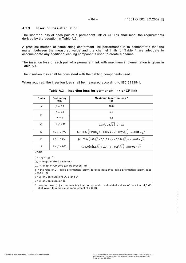
– 84 – 11801 © ISO/IEC:2002(E)
A.2.3 Insertion loss/attenuation
The insertion loss of each pair of a permanent link or CP link shall meet the requirementsderived by the equation in Table A.3.
A practical method of establishing conformant link performance is to demonstrate that themargin between the measured value and the channel limits of Table 4 are adequate toaccommodate any additional cabling components used to create a channel.
The insertion loss of each pair of a permanent link with maximum implementation is given inTable A.4.
The insertion loss shall be consistent with the cabling components used.
When required, the insertion loss shall be measured according to IEC 61935-1.
Table A.3 – Insertion loss for permanent link or CP link
Class FrequencyMHz
Maximum insertion loss a
dB
A 0,1=f 16,0
0,1=f 5,5B
1=f 5,8
C 161 ≤≤ f ( ) 0,233,230,9 ×+× f
D 1001 ≤≤ f ( ) ( ) fnfffL ××++×+× 0,040,22 0,0228 1,910/100
E 2501 ≤≤ f ( ) ( ) fnfffL ××++×+× 0,020,259 0,0161,82/100
F 6001 ≤≤ f ( ) ( ) fnfffL ××++×+× 0,020,20,011,8/100
NOTE:
L = LFC + LCP YLFC = length of fixed cable (m)LCP = length of CP cord (where present) (m)Y = the ratio of CP cable attenuation (dB/m) to fixed horizontal cable attenuation (dB/m) (seeClause 13)n = 2 for Configurations A, B and Dn = 3 for Configuration Ca Insertion loss (IL) at frequencies that correspond to calculated values of less than 4,0 dB
shall revert to a maximum requirement of 4,0 dB.
COPYRIGHT 2004; International Organization for Standardization
Document provided by IHS Licensee=Avaya/5937902101, User=, 01/05/2004 01:59:27MST Questions or comments about this message: please call the Document PolicyGroup at 1-800-451-1584.
--``,,`,`````,,,`,,`,`,,````,-`-`,,`,,`,`,,`---

11801 © ISO/IEC:2002(E) – 85 –
Table A.4 – Informative insertion loss values for permanent link withmaximum implementation at key frequencies
Maximum insertion lossdBFrequency
MHzClass A Class B Class C Class D Class E Class F
0,1 16,0 5,5 N/A N/A N/A N/A
1 N/A 5,8 4,0 4,0 4,0 4,0
16 N/A N/A 12,2 7,7 7,1 6,9
100 N/A N/A N/A 20,4 18,5 17,7
250 N/A N/A N/A N/A 30,7 28,8
600 N/A N/A N/A N/A N/A 46,6
A.2.4 NEXT
A.2.4.1 Pair-to-pair NEXT
The NEXT between each pair combination of a permanent link or CP link shall meet therequirements derived by the equation in Table A.5.
The NEXT between each pair combination of a permanent link with maximum implementationis given in Table A.6.
The NEXT requirements shall be met at both ends of the cabling. NEXT values at frequencieswhere the insertion loss (IL) is below 4,0 dB are for information only.
The NEXT shall be consistent with the cabling components used.
When required the NEXT shall be measured according to IEC 61935-1.
COPYRIGHT 2004; International Organization for Standardization
Document provided by IHS Licensee=Avaya/5937902101, User=, 01/05/2004 01:59:27MST Questions or comments about this message: please call the Document PolicyGroup at 1-800-451-1584.
--``,,`,`````,,,`,,`,`,,````,-`-`,,`,,`,`,,`---

– 86 – 11801 © ISO/IEC:2002(E)
Table A.5 – NEXT for permanent link or CP link
Class FrequencyMHz
Minimum NEXTdB
A 0,1=f 27,0
B 10,1 ≤≤ f f)lg( 15-25
C 161 ≤≤ f )lg( 15,8-40,1 f
D 1001 ≤≤ f
− −
−
+−−
20)( lg 2083
1020( lg 1565,3
10 lg 20ff)
a
E 2501 ≤≤ f
− −
−
+−−
20)( lg 2094
1020)( lg 1574,3
10 lg 20ff
b
F 6001 ≤≤ f
− −
−
+−−
20)( lg 51102,4
1020)( lg 15102,4
10 lg 20ff
b
a NEXT at frequencies that correspond to calculated values of greater than 60,0 dB shall revert to a minimumrequirement of 60,0 dB.
b NEXT at frequencies that correspond to calculated values of greater than 65,0 dB shall revert to a minimumrequirement of 65,0 dB.
Table A.6 – Informative NEXT values for permanent link with maximum implementationat key frequencies
Minimum NEXTdBFrequency
MHzClass A Class B Class C Class D Class E Class F
0,1 27,0 40,0 N/A N/A N/A N/A
1 N/A 25,0 40,1 60,0 65,0 65,0
16 N/A N/A 21,1 45,2 54,6 65,0
100 N/A N/A N/A 32,3 41,8 65,0
250 N/A N/A N/A N/A 35,3 60,4
600 N/A N/A N/A N/A N/A 54,7
A.2.4.2 Power sum NEXT (PS NEXT)
The PS NEXT requirements are applicable only to classes D, E and F.
The PS NEXT of each pair of a permanent link or CP link shall meet the requirements derivedby the equation in Table A.7.
The PS NEXT of each pair of a permanent link with maximum implementation is given inTable A.8.
The PS NEXT requirements shall be met at both ends of the cabling. PS NEXT values atfrequencies where the insertion loss (IL) is below 4,0 dB are for information only.
The PS NEXT shall be consistent with the cabling components used.
COPYRIGHT 2004; International Organization for Standardization
Document provided by IHS Licensee=Avaya/5937902101, User=, 01/05/2004 01:59:27MST Questions or comments about this message: please call the Document PolicyGroup at 1-800-451-1584.
--``,,`,`````,,,`,,`,`,,````,-`-`,,`,,`,`,,`---

11801 © ISO/IEC:2002(E) – 87 –
PS NEXTk of pair k is computed as follows:
∑≠=
−
−=n
NEXTik
PS NEXTkii
k1,
1010lg 10 (A.1)
wherei is the number of the disturbing pair;k is the number of the disturbed pair;n is the total number of pairs;NEXTik is the near end crosstalk loss coupled from pair i into pair k.
Table A.7 – PS NEXT for permanent link or CP link
Class FrequencyMHz
Minimum PS NEXTdB
D 1001 ≤≤ f
−
−
+−−
− 20)( lg 2080
1020)( lg 1562,3
10 lg 20ff
a
E 2501 ≤≤ f
−
−
+−−
− 20)( lg 2090
1020)( lg 1572,3
10 lg 20ff
b
F 6001 ≤≤ f
−−
+−−
− 20)( lg 1599,4
1020)( lg 1599,4
10 lg 20ff
b
a PS NEXT at frequencies that correspond to calculated values of greater than 57,0 dB shall revert to aminimum requirement of 57,0 dB.
b PS NEXT at frequencies that correspond to calculated values of greater than 62,0 dB shall revert to aminimum requirement of 62,0 dB.
COPYRIGHT 2004; International Organization for Standardization
Document provided by IHS Licensee=Avaya/5937902101, User=, 01/05/2004 01:59:27MST Questions or comments about this message: please call the Document PolicyGroup at 1-800-451-1584.
--``,,`,`````,,,`,,`,`,,````,-`-`,,`,,`,`,,`---

– 88 – 11801 © ISO/IEC:2002(E)
Table A.8 – Informative PS NEXT values for permanent link withmaximum implementation at key frequencies
Minimum PS NEXTdBFrequency
MHzClass D Class E Class F
1 57,0 62,0 62,0
16 42,2 52,2 62,0
100 29,3 39,3 62,0
250 N/A 32,7 57,4
600 N/A N/A 51,7
A.2.5 Attenuation to crosstalk ratio (ACR)
The ACR requirements are applicable only to Classes D, E and F.
A.2.5.1 Pair-to-pair ACR
Pair-to-pair ACR is the difference between the pair-to-pair NEXT and the insertion loss of thecabling in dB.
The ACR of each pair combination of a permanent link or CP link shall meet the difference ofthe NEXT requirement of Table A.5 and the insertion loss requirement of Table A.3 of therespective class.
The ACR of each pair combination of a permanent link with maximum implementation is givenin Table A.9.
The ACR requirements shall be met at both ends of the cabling. ACR values at frequencieswhere the insertion loss (IL) is below 4,0 dB are for information only.
ACRik of pairs i and k is computed as follows:
kikik ILNEXTACR −= (A.2)
wherei is the number of the disturbing pair;k is the number of the disturbed pair;NEXTik is the near end crosstalk loss coupled from pair i into pair k;ILk is the insertion loss of pair k. When required, it shall be measured according to
IEC 61935-1.
COPYRIGHT 2004; International Organization for Standardization
Document provided by IHS Licensee=Avaya/5937902101, User=, 01/05/2004 01:59:27MST Questions or comments about this message: please call the Document PolicyGroup at 1-800-451-1584.
--``,,`,`````,,,`,,`,`,,````,-`-`,,`,,`,`,,`---

11801 © ISO/IEC:2002(E) – 89 –
Table A.9 – Informative ACR values for permanent link withmaximum implementation at key frequencies
Minimum ACRdBFrequency
MHzClass D Class E Class F
1 56,0 61,0 61,0
16 37,5 47,5 58,1
100 11,9 23,3 47,3
250 N/A 4,7 31,6
600 N/A N/A 8,1
A.2.5.2 Power sum ACR (PS ACR)
The PS ACR of each pair of a permanent link or CP link shall meet the difference of thePS NEXT requirement of Table A.7 and the insertion loss requirement of Table A.3 of therespective class.
The PS ACR of each pair of a permanent link with maximum implementation is given in TableA.10.
The PS ACR requirements shall be met at both ends of the cabling. PS ACR values atfrequencies where the insertion loss (IL) is below 4,0 dB are for information only.
PS ACRk of pair k is computed as follows:
kkk ILPS NEXTPS ACR −= (A.3)
wherek is the number of the disturbed pair;PS NEXTk is the power sum near end crosstalk loss of pair k;ILk is the insertion loss of pair k. When required, it shall be measured according to
IEC 61935-1.
Table A.10 – Informative PS ACR values for permanent link withmaximum implementation at key frequencies
Minimum PS ACRdBFrequency
MHzClass D Class E Class F
1 53,0 58,0 58,0
16 34,5 45,1 55,1
100 8,9 20,8 44,3
250 N/A 2,0 28,6
600 N/A N/A 5,1
A.2.6 ELFEXT
The ELFEXT requirements are applicable only to Classes D, E and F.
COPYRIGHT 2004; International Organization for Standardization
Document provided by IHS Licensee=Avaya/5937902101, User=, 01/05/2004 01:59:27MST Questions or comments about this message: please call the Document PolicyGroup at 1-800-451-1584.
--``,,`,`````,,,`,,`,`,,````,-`-`,,`,,`,`,,`---

– 90 – 11801 © ISO/IEC:2002(E)
A.2.6.1 Pair-to-pair ELFEXT
The ELFEXT of each pair combination of a permanent link or CP link shall meet therequirements derived by the equation Table A.11.
The ELFEXT of each pair combination of a permanent link with maximum implementation isgiven in Table A.12.
The ELFEXT shall be consistent with the cabling components used.
ELFEXTik of pairs i and k is computed as follows:
kikik ILFEXTELFEXT −= (A.4)
wherei is the number of the disturbed pair;k is the number of the disturbing pair;FEXTik is the far end crosstalk loss coupled from pair i into pair k. When required, it shall be
measured according to IEC 61935-1:ILk is the insertion loss of pair k. When required, it shall be measured according to
IEC 61935-1.NOTE The ratio of the insertion loss of the disturbed pair to the input-to-output FEXT is relevant for the signal-to-noise-ratio consideration. The results computed according to the formal definition above cover all possiblecombinations of insertion loss of wire pairs and corresponding input-to-output FEXT.
Table A.11 – ELFEXT for permanent link or CP link
Class FrequencyMHz
Minimum ELFEXT a
dB
D 1001 ≤≤ f
−
−
×+−−
− 20)( lg 2075,1
1020)( lg 2063,8
10 lg 20
f
n
f
b
E 2501 ≤≤ f
−
−
×+−−
− 20)( lg 2083,1
1020)( lg 2067,8
10 lg 20
f
n
f
c
F 6001 ≤≤ f
−
−
×+−−
− 20)( lg 1590
1020)( lg 2094
10 lg 20
f
n
f
c
NOTE n = 2 for Configurations A, B and Dn = 3 for Configuration C
a ELFEXT at frequencies that correspond to measured FEXT values of greater than 70,0 dB are forinformation only.
b ELFEXT at frequencies that correspond to calculated values of greater than 60,0 dB shall revert to aminimum requirement of 60,0 dB.
c ELFEXT at frequencies that correspond to calculated values of greater than 65,0 dB shall revert to aminimum requirement of 65,0 dB.
COPYRIGHT 2004; International Organization for Standardization
Document provided by IHS Licensee=Avaya/5937902101, User=, 01/05/2004 01:59:27MST Questions or comments about this message: please call the Document PolicyGroup at 1-800-451-1584.
--``,,`,`````,,,`,,`,`,,````,-`-`,,`,,`,`,,`---

11801 © ISO/IEC:2002(E) – 91 –
Table A.12 – Informative ELFEXT values for permanent link withmaximum implementation at key frequencies
Minimum ELFEXTdBFrequency
MHzClass D Class E Class F
1 58,6 64,2 65,0
16 34,5 40,1 59,3
100 18,6 24,2 46,0
250 N/A 16,2 39,2
600 N/A N/A 32,6
A.2.6.2 Power sum ELFEXT (PS ELFEXT)
The PS ELFEXT of each pair of a permanent link or CP link shall meet the requirementsderived by the equation in Table A.13.
The PS ELFEXT of each pair of a permanent link with maximum implementation is given inTable A.14.
The PS ELFEXT shall be consistent with the cabling components used.
PS ELFEXTk of pair k is computed as follows:
∑≠=
−
−=n
ELFEXT
k
ik
PS ELFEXTkii 1,
1010lg 10 (A.5)
wherei is the number of the disturbing pair;k is the number of the disturbed pair;n is the total number of pairs;ELFEXTik is the equal level far end crosstalk loss coupled from pair i into pair k.
COPYRIGHT 2004; International Organization for Standardization
Document provided by IHS Licensee=Avaya/5937902101, User=, 01/05/2004 01:59:27MST Questions or comments about this message: please call the Document PolicyGroup at 1-800-451-1584.
--``,,`,`````,,,`,,`,`,,````,-`-`,,`,,`,`,,`---

– 92 – 11801 © ISO/IEC:2002(E)
Table A.13 – PS ELFEXT for permanent link or CP link
Class FrequencyMHz
Minimum PS ELFEXT a
dB
D 1001 ≤≤ f
−−
×+−−
− 20)( lg 2072,1
1020)( lg 2060,8
10 lg 20f
n
f
b
E 2501 ≤≤ f
−−
×+−−
− 20)( lg 2080,1
1020)( lg 2064,8
10 lg 20f
n
f
c
F 6001 ≤≤ f
−
−
×+−−
− 20)( lg 1587
1020)( lg 2091
10 lg 20f
n
f
c
NOTE n = 2 for configurations A, B and Dn = 3 for configuration C
a PS ELFEXT at frequencies that correspond to measured FEXT values of greater than 70,0 dB are forinformation only.
b PS ELFEXT at frequencies that correspond to calculated values of greater than 57,0 dB shall revert to aminimum requirement of 57,0 dB.
c PS ELFEXT at frequencies that correspond to calculated values of greater than 62,0 dB shall revert to aminimum requirement of 62,0 dB.
Table A.14 – Informative PS ELFEXT values for permanent link with maximumimplementation at key frequencies
Minimum PS ELFEXTdBFrequency
MHzClass D Class E Class F
1 55,6 61,2 62,0
16 31,5 37,1 56,3
100 15,6 21,2 43,0
250 N/A 13,2 36,2
600 N/A N/A 29,6
A.2.7 Direct current (d.c.) loop resistance
The d.c. loop resistance of each pair of a permanent link or CP link shall meet therequirements derived by the equation in Table A.15.
A practical method of establishing conformant link performance is to demonstrate that themargin between the measured value and the channel limits of Table 16 are adequate toaccommodate any additional cabling components used to create a channel. This is fulfilled ifthe insertion loss requirement and the delay skew requirement for the permanent link or CPlink are met.
The d.c. loop resistance of each pair of a permanent link with maximum implementation isgiven in Table A.16.
The d.c. loop resistance shall be consistent with the cabling components used.
COPYRIGHT 2004; International Organization for Standardization
Document provided by IHS Licensee=Avaya/5937902101, User=, 01/05/2004 01:59:27MST Questions or comments about this message: please call the Document PolicyGroup at 1-800-451-1584.
--``,,`,`````,,,`,,`,`,,````,-`-`,,`,,`,`,,`---

11801 © ISO/IEC:2002(E) – 93 –
When required, the d.c. loop resistance shall be measured according to IEC 61935-1.
Table A.15 – Direct current (d.c.) loop resistance for permanent link or CP link
Class Maximum d.c. loop resistanceΩ
A 530
B 140
C 34
D (L/100) × 22 + n × 0,4
E (L/100) × 22 + n × 0,4
F (L/100) × 22 + n × 0,4
NOTEL LFC + LCP × Y
LFC length of fixed cable (m)
LCP length of CP cord (where present) (m)
Y the ratio of CP cable attenuation (dB/m) to fixed horizontal cableattenuation (dB/m) (see Clause 13)
n 2 for Configurations A, B and D
n 3 for Configuration C
Table A.16 – Informative d.c. loop resistance for permanent link withmaximum implementation
Maximum d.c. loop resistanceΩ
Class A Class B Class C Class D Class E Class F
530 140 34 21 21 21
A.2.8 Direct current (d.c.) resistance unbalance
The d.c. resistance unbalance between the two conductors within all pairs of a permanent linkor CP link shall not exceed 3 % for all classes. This shall be achieved by design.
A.2.9 Propagation delay
The propagation delay of each pair of a permanent link or CP link shall meet the requirementsderived by the equation in Table A.17.
A practical method of establishing conformant link performance is to demonstrate that themargin between the measured value and the channel limits of Table 17 are adequate toaccommodate any additional cabling components used to create a channel. This is fulfilled ifthe insertion loss requirement and the delay skew requirement for the permanent link or CPlink are met.
The propagation delay of each pair of a permanent link with maximum implementation is givenin Table A.18.
The propagation delay shall be consistent with the cabling components used.
When required, the propagation delay shall be measured according to IEC 61935-1.
COPYRIGHT 2004; International Organization for Standardization
Document provided by IHS Licensee=Avaya/5937902101, User=, 01/05/2004 01:59:27MST Questions or comments about this message: please call the Document PolicyGroup at 1-800-451-1584.
--``,,`,`````,,,`,,`,`,,````,-`-`,,`,,`,`,,`---

– 94 – 11801 © ISO/IEC:2002(E)
Table A.17 – Propagation delay for permanent link or CP link
Class FrequencyMHz
Maximum propagation delayµs
A 0,1=f 19,400
B 10,1 ≤≤ f 4,400
C 161 ≤≤ f ( ) ( ) 5 0,0020,0360,534 /100 ×++× nfL
D 1001 ≤≤ f ( ) ( ) 5 0,0020,0360,534 /100 ×++× nfL
E 2501 ≤≤ f ( ) ( ) 5 0,0020,0360,534 /100 ×++× nfL
F 6001 ≤≤ f ( ) ( ) 5 0,0020,0360,534 /100 ×++× nfL
NOTE
L LFC + LCP
LFC length of fixed cable (m)
LCP length of CP cord (where present) (m)
n 2 for configurations A, B and D
n 3 for configuration C
Table A.18 – Informative propagation delay values for permanent link withmaximum implementation at key frequencies
Maximum propagation delayµsFrequency
MHzClass A Class B Class C Class D Class E Class F
0,1 19,400 4,400 N/A N/A N/A N/A
1 N/A 4,400 0,521 0,521 0,521 0,521
16 N/A N/A 0,496 0,496 0,496 0,496
100 N/A N/A N/A 0,491 0,491 0,491
250 N/A N/A N/A N/A 0,490 0,490
600 N/A N/A N/A N/A N/A 0,489
A.2.10 Delay skew
The delay skew between all pairs of a permanent link or CP link shall meet the requirementsderived by the equation in Table A.19.
A practical method of establishing a conformant link performance is to demonstrate that themargin between the measured value and the channel limits of Table A.19 are adequate toaccommodate any additional cabling components used to create a channel. This is fulfilled ifthe insertion loss requirement and the delay skew requirement for the permanent link or CPlink are met.
The delay skew between all pairs of a permanent link with maximum implementation is givenin Table A.20.
The delay skew shall be consistent with the cabling components used.
When required, the delay skew shall be measured according to IEC 61935-1.
COPYRIGHT 2004; International Organization for Standardization
Document provided by IHS Licensee=Avaya/5937902101, User=, 01/05/2004 01:59:27MST Questions or comments about this message: please call the Document PolicyGroup at 1-800-451-1584.
--``,,`,`````,,,`,,`,`,,````,-`-`,,`,,`,`,,`---

11801 © ISO/IEC:2002(E) – 95 –
Table A.19 – Delay skew for permanent link or CP link
Class FrequencyMHz
Maximum delay skewµs
A 0,1=f N/A
B 10,1 ≤≤ f N/A
C 161 ≤≤ f ( ) 250,0010,045 /100 ×+× nL
D 1001 ≤≤ f ( ) 250,0010,045 /100 ×+× nL
E 2501 ≤≤ f ( ) 250,0010,045 /100 ×+× nL
F 6001 ≤≤ f ( ) 250,0010,025 /100 ×+× nL
NOTE
L LFC + LCP
LFC length of fixed cable (m)
LCP length of CP cord (where present) (m)
n 2 for configurations A, B and D
n 3 for configuration C
Table A.20 – Informative delay skew for permanent link with maximum implementation
Class FrequencyMHz
Maximum delay skewµs
A 0,1=f N/A
B 0,1 ≤ f ≤ 1 N/A
C 161 ≤≤ f 0,044 a
D 1001 ≤≤ f 0,044 a
E 2501 ≤≤ f 0,044 a
F 6001 ≤≤ f 0,026 b
a This is the result of the calculation 0,9*0,045+3 × 0,001 25.b This is the result of the calculation 0,9*0,025+3 × 0,001 25.
COPYRIGHT 2004; International Organization for Standardization
Document provided by IHS Licensee=Avaya/5937902101, User=, 01/05/2004 01:59:27MST Questions or comments about this message: please call the Document PolicyGroup at 1-800-451-1584.
--``,,`,`````,,,`,,`,`,,````,-`-`,,`,,`,`,,`---
– 96 – 11801 © ISO/IEC:2002(E)
Annex B (normative)
Test procedures
B.1 General
This annex on test procedures is divided into four parts. B.1 gives general information. B.2gives references to test procedures for installed cabling and for cabling in laboratoryenvironment. B.3 gives references to test procedures for prefabricated cords. B.4 givesreferences to test procedures for individual components.
B.2 Channel and link performance testing
B.2.1 Testing balanced cabling channels, permanent links and CP links
The test procedures for balanced cabling installations are specified in IEC 61935-1
B.2.2 Testing optical fibre cabling channels
The test procedures for optical cabling installations are specified in ISO/IEC TR 14763-3.
NOTE If test methods for some parameters are missing in the referenced standard, they can be found in theoptical cable standards IEC 60794-1 or IEC 60793-1-XX.
B.2.3 Channel and link test schedules
Channels and links are normally tested for compliance with the specified requirements afterinstallation. For these tests 'in field' test instruments are available. The channels andpermanent links may also be tested in laboratory environments. This is in order to provecompliance for systems made up of specific components. These tests may use laboratoryequipment or field test equipment. Tests using laboratory test instruments, which are carriedout according to international standards, may be reference tests which can be used toevaluate the accuracy of field test equipment.
NOTE If field testers are not available for testing of certain classes of cabling, laboratory equipment can be used.For testing parameters, which require access to both ends of the installed cabling, laboratory equipment is notpractical. It is recommended that this cabling is installed in such a way that only acceptance testing (see thedefinition below) is required.
The different kinds of testing may be classified as follows:
a) Acceptance testingAs a means of validating installed cabling, which is known to comply with theimplementation requirements of this standard and which is made up of elementscomplying with the performance requirements for components for the relevant categories.
b) Compliance testingAs a means of validating installed cabling, comprising known or unknown components.
c) Reference testingAs a means for testing cabling models in laboratory environment and for comparing theresult of measurements performed with laboratory and field test instruments. Referencetesting in laboratory on cabling models is also used for verifying compliance for properties,which cannot be tested in field.
COPYRIGHT 2004; International Organization for Standardization
Document provided by IHS Licensee=Avaya/5937902101, User=, 01/05/2004 01:59:27MST Questions or comments about this message: please call the Document PolicyGroup at 1-800-451-1584.
--``,,`,`````,,,`,,`,`,,````,-`-`,,`,,`,`,,`---

11801 © ISO/IEC:2002(E) – 97 –
In Table B.1, the type of test to be carried out for each channel or permanent link is indicatedby an "I" (informative) or "N" (normative). Parameters, which are computed from the measuredparameters, are indicated by a "C". The tests indicated by “I” may be carried out as part of anacceptance test. The tests indicated by “N” shall be carried out as part of an acceptance,reference or compliance test.
Table B.1 – Cabling characteristics of copper and optical fibre cablingfor acceptance, compliance and reference testing
Testing forCharacteristics ofcopper cabling Acceptance Compliance Reference
Return loss I N N
Insertion loss I N N
NEXT I N N
PS NEXT C C C
ACR I N N
PS ACR I C C
ELFEXT I N N
PS ELFEXT C C C
DC loop resistance I N N
Propagation delay I N N
Skew I N N
Unbalance attenuation, near end (TCL) N
Coupling attenuation f.f.s.
Length a I I N
Wiremap N N N
Continuity of conductors, screens (ifapplicable), short and open circuits N N N
a Length is not a pass/fail criterion
Testing forCharacteristics ofoptical fibre cabling Acceptance Compliance Reference
Optical attenuation N N N
Multimode modal bandwidth N
Propagation delay I N N
Length C C C
Continuity and maintenance of polarity N N N
Cabling characteristics to be tested for acceptance, compliance and reference shall meet orexceed the requirements outlined in 6.4 for balanced cabling and in Clause 8 for opticalcabling.
B.3 Transmission testing of cords for balanced cabling
Testing of cords for balanced cabling shall be performed according to IEC 61935-2.
COPYRIGHT 2004; International Organization for Standardization
Document provided by IHS Licensee=Avaya/5937902101, User=, 01/05/2004 01:59:27MST Questions or comments about this message: please call the Document PolicyGroup at 1-800-451-1584.
--``,,`,`````,,,`,,`,`,,````,-`-`,,`,,`,`,,`---

– 98 – 11801 © ISO/IEC:2002(E)
B.4 Transmission testing of components for cabling
B.4.1 Transmission testing of copper cables for balanced cabling
Testing of cables for balanced cabling shall be performed according to IEC 61156-1.
B.4.2 Transmission testing of connecting hardware for balanced cabling
Testing of connecting hardware for balanced cabling shall be performed according to therelevant part of IEC 60603-7. If connecting hardware is used that is not covered by theIEC 60603-7 series, it shall be tested according to the relevant specification.
B.4.3 Transmission testing of cables for optical cabling
Testing of cables for optical cabling shall be performed according to the IEC 60794-2 seriesfor indoor cables and the IEC 60794-3 series for outdoor cables.
B.4.4 Transmission testing of connectors for optical cabling
Testing of connectors for optical cabling shall be performed according to IEC 61300-3-34.
COPYRIGHT 2004; International Organization for Standardization
Document provided by IHS Licensee=Avaya/5937902101, User=, 01/05/2004 01:59:27MST Questions or comments about this message: please call the Document PolicyGroup at 1-800-451-1584.
--``,,`,`````,,,`,,`,`,,````,-`-`,,`,,`,`,,`---

11801 © ISO/IEC:2002(E) – 99 –
Annex C (normative)
Mechanical and environmental performance testing of connectinghardware for balanced cabling
C.1 Introduction
The mechanical and environmental performance of connecting hardware is vital to the cablingsystem. Changes in contact resistance because of operational and environmental stress cannegatively affect the transmission characteristics of the cabling system. Product life testing isaccomplished by subjecting the product to a number of mechanical and environmentalconditions and measuring any resistance deviations at prescribed intervals and aftercompletion of each conditioning sequence. In addition, the product shall not show evidence ofdegradation with respect to the ease of mechanical termination, safety or other functionalattributes at any time during or after environmental conditioning.
To ensure that all connecting hardware for balanced cabling systems will perform reliablyunder field installation conditions, it shall be capable of maintaining reliable connectionsthroughout the series of environmental conditioning and testing illustrated in Table C.2 toTable C.5. Products under test shall be mounted and connected in accordance withmanufacturer's guidelines. Unless otherwise specified, tests should be carried out understandard atmospheric conditions in accordance with 5.3.1 of IEC 60068-1.
NOTE 1 This annex provides mechanical connection performance requirements for connections that are notcovered by a specific IEC connector standard. It is intended to replace the specifications in this annex by referenceto international standards, as they become available.
NOTE 2 Connection interfaces that conform to the mechanical and environmental performance requirements ofIEC 60603-7 (unscreened) or IEC 60603-7-1 (screened) are exempt from this annex. Connection interfaces that arecovered by international standards other than the IEC 60603-7 series shall comply with at least the equivalentmechanical and environmental performance requirements specified in this annex.
C.2 Test requirements
C.2.1 General
This test schedule shows all tests and the order in which they shall be carried out, as well asthe requirements to be met.
Unless otherwise specified, connecting hardware shall be tested in the mated or terminatedstate. Care shall be taken to keep a particular combination of connecting hardware togetherduring the complete test sequence. That is, when unmating is necessary for a certain test, thesame connecting hardware shall be mated for the subsequent tests.
Hereinafter, mated/terminated connecting hardware is called the "specimen".
For each group, a minimum of 10 product samples shall be used to compile data forsupporting a conclusion that pass criteria are satisfied.
C.2.2 Initial test measurements
All specimens shall be subjected to the measurements and sequence shown in Table C.1.
COPYRIGHT 2004; International Organization for Standardization
Document provided by IHS Licensee=Avaya/5937902101, User=, 01/05/2004 01:59:27MST Questions or comments about this message: please call the Document PolicyGroup at 1-800-451-1584.
--``,,`,`````,,,`,,`,`,,````,-`-`,,`,,`,`,,`---

– 100 – 11801 © ISO/IEC:2002(E)
Table C.1 – Group P
Test Measurement to be performedTest
phase Title IEC 60512Test No.
Severity or conditionof test Title IEC 60512
Test No. Requirements
Visualexamination 1a
There shall be nodefects that wouldimpair normal operation
P 1 Generalexamination 1
Examinationof dimensionsand mass
1b
The dimensions shallcomply with thosespecified in the detailspecification
P 2 Polarization(if applicable)
P 3 Contactresistance
All signal contacts andscreen/specimens(bulk resistancesubtracted)
Millivolt levelmethod 2a Contact resistance =
20 mΩ maximum
P 4
Test voltage100 V ± 15 V d.c.Method A
Mated or terminatedconnectors
Insulationresistance 3a 500 MΩ minimum
Contact/contactMethod AMated or terminatedconnectors
1 000 V d.c. or a.c.peak
P 5 All contacts to screen:Method A
Mated or terminatedconnectors
Voltage proof 4a
1 500 V d.c. or a.c.peak
C.2.3 Environmental and mechanical performance
The specimens shall be divided into four groups, group A, group B, group C and group D.Connecting hardware in each group shall undergo the tests specified in the relevant group.
COPYRIGHT 2004; International Organization for Standardization
Document provided by IHS Licensee=Avaya/5937902101, User=, 01/05/2004 01:59:27MST Questions or comments about this message: please call the Document PolicyGroup at 1-800-451-1584.
--``,,`,`````,,,`,,`,`,,````,-`-`,,`,,`,`,,`---
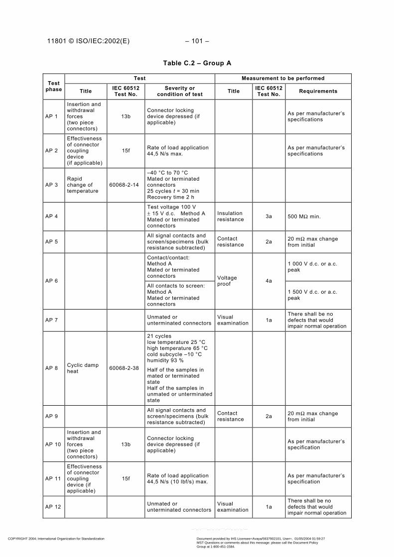
11801 © ISO/IEC:2002(E) – 101 –
Table C.2 – Group A
Test Measurement to be performedTest
phase Title IEC 60512Test No.
Severity orcondition of test Title IEC 60512
Test No. Requirements
AP 1
Insertion andwithdrawalforces(two piececonnectors)
13bConnector lockingdevice depressed (ifapplicable)
As per manufacturer’sspecifications
AP 2
Effectivenessof connectorcouplingdevice(if applicable)
15f Rate of load application44,5 N/s max.
As per manufacturer’sspecifications
AP 3Rapidchange oftemperature
60068-2-14
–40 °C to 70 °CMated or terminatedconnectors25 cycles t = 30 minRecovery time 2 h
AP 4
Test voltage 100 V± 15 V d.c. Method AMated or terminatedconnectors
Insulationresistance 3a 500 MΩ min.
AP 5All signal contacts andscreen/specimens (bulkresistance subtracted)
Contactresistance 2a 20 mΩ max change
from initial
Contact/contact:Method AMated or terminatedconnectors
1 000 V d.c. or a.c.peak
AP 6All contacts to screen:Method AMated or terminatedconnectors
Voltageproof 4a
1 500 V d.c. or a.c.peak
AP 7 Unmated orunterminated connectors
Visualexamination 1a
There shall be nodefects that wouldimpair normal operation
AP 8 Cyclic dampheat 60068-2-38
21 cycleslow temperature 25 °Chigh temperature 65 °Ccold subcycle –10 °Chumidity 93 %
Half of the samples inmated or terminatedstateHalf of the samples inunmated or unterminatedstate
AP 9All signal contacts andscreen/specimens (bulkresistance subtracted)
Contactresistance 2a 20 mΩ max change
from initial
AP 10
Insertion andwithdrawalforces(two piececonnectors)
13bConnector lockingdevice depressed (ifapplicable)
As per manufacturer’sspecification
AP 11
Effectivenessof connectorcouplingdevice (ifapplicable)
15f Rate of load application44,5 N/s (10 lbf/s) max.
As per manufacturer’sspecification
AP 12 Unmated orunterminated connectors
Visualexamination 1a
There shall be nodefects that wouldimpair normal operation
COPYRIGHT 2004; International Organization for Standardization
Document provided by IHS Licensee=Avaya/5937902101, User=, 01/05/2004 01:59:27MST Questions or comments about this message: please call the Document PolicyGroup at 1-800-451-1584.
--``,,`,`````,,,`,,`,`,,````,-`-`,,`,,`,`,,`---

– 102 – 11801 © ISO/IEC:2002(E)
Table C.3 – Group B
Test Measurement to be performedTest
phase Title IEC 60512Test No.
Severity or conditionof test Title IEC 60512
Test No. Requirements
BP 1
Lockingdevicemechanicaloperations (ifapplicable)
Mechanical operations
As per manufacturer’sspecification, butequivalent to N = 200insertions andwithdrawals
BP 2 Mechanicaloperations 9a
N/2 operations Speed10 mm/s rest 5 s (twopiece connectors).Locking deviceinoperative
N = 200
BP 3Flowingmixed gascorrosion
11-7
4 daysHalf of the samples inmated or terminatedstateHalf of the samples inunmated orunterminated state
Mixture of gases:SO2 = (0,5 ± 0,1) 10-6
(vol/vol)H2S = (0,1 ± 0,02) 10-6
(vol/vol)Temperature:(25 ± 2) °CRelative humidity:(75 ± 3) %
BP 4
All signal contacts andscreen / specimens(bulk resistancesubtracted)
Contactresistance 2a 20 mΩ maximum
change from initial
BP 5 Mechanicaloperations 9a
N/2 operationsSpeed 10 mm/s. Rest5 s (two piececonnectors). Lockingdevice inoperative
BP 6 All signal contacts andscreen / specimens
Contactresistance 2a 20 mΩ maximum
change from initial
BP 7
100 V + 15 V d.c.Method AMated or terminatedconnectors
Insulationresistance 3a 500 MΩ Min.
Contact/contact:Method AMated or terminatedconnectors
1 000 V d.c. or a.c.peak
BP 8All contacts to screen:Method AMated or terminatedconnectors
Voltageproof 4a
1 500 V d.c. or a.c.peak
BP 9 Visualexamination 1a
There shall be nodefects that wouldimpair normal operation
COPYRIGHT 2004; International Organization for Standardization
Document provided by IHS Licensee=Avaya/5937902101, User=, 01/05/2004 01:59:27MST Questions or comments about this message: please call the Document PolicyGroup at 1-800-451-1584.
--``,,`,`````,,,`,,`,`,,````,-`-`,,`,,`,`,,`---

11801 © ISO/IEC:2002(E) – 103 –
Table C.4 – Group C
Test Measurement to be performedTest
phase Title IEC 60512Test No.
Severity or conditionof test Title IEC 60512
Test No. Requirements
CP 1 Vibration 11cMeasurement points asper manufacturer’sspecification
Contactdisturbance 2e 10 µs max.
CP 2
Test voltage100 V d.c.Method AMated or terminatedconnectors
Insulationresistance 3a 500 MΩ min.
CP 3All signal contacts andscreen/specimens (bulkresistance subtracted)
Contactresistance 2a 20 mΩ max. change
from initial
CP 4Unmated orunterminatedconnectors
Visualexamination 1a
There shall be nodefects that wouldimpair normal operation
Table C.5 – Group D
Test Measurement to be performedTest
phase Title IEC 60512Test No.
Severity or conditionof test Title IEC 60512
Test No. Requirements
DP 1Electricalload andtemperature
9b5 connectors
500 h, 70 °CRecovery period 2 h
0,5A, 5 connectors
No current,5 connectors
DP 2
Test voltage100 V d.c.Method AMated or terminatedconnectors
Insulationresistance 3a 500 MΩ min.
Contact/contact:Method AMated or terminatedconnectors
1 000 V d.c. or a.c.peak
DP 3All contacts to screen:Method AMated or terminatedconnectors
Voltageproof 4a
1 500 V d.c. or a.c.peak
DP 4Unmated orunterminatedconnectors
Visualexamination 1a
There shall be nodefects that wouldimpair normal operation
DP 5
All signal contacts andscreen / specimens(bulk resistancesubtracted)
Contactresistance 1a 20 mΩ max. change
from initial
COPYRIGHT 2004; International Organization for Standardization
Document provided by IHS Licensee=Avaya/5937902101, User=, 01/05/2004 01:59:27MST Questions or comments about this message: please call the Document PolicyGroup at 1-800-451-1584.
--``,,`,`````,,,`,,`,`,,````,-`-`,,`,,`,`,,`---
– 104 – 11801 © ISO/IEC:2002(E)
Annex D (informative)
Electromagnetic characteristics
Cabling consists of passive components and can therefore only be verified for conformance toelectromagnetic compliance (CISPR 22 and CISPR 24) when attached to application specificequipment. However, electromagnetic characteristics of a network installation are influencedby parameters, such as the balance and/or screening properties of the cabling.
Balance is characterised by unbalance attenuation, i.e. the ratio between the unwantedcommon mode signal power and the injected differential mode signal power. This commonmode signal which arises from imperfections in the cabling system, such as asymmetry,causes electromagnetic emission and affects noise immunity. Unbalance attenuation ischaracterised for components, including cables and connecting hardware. Limits forunbalance attenuation are also given for cabling. Unbalance attenuation test methods forcomponents are well established for frequencies up to 100 MHz.
Screening effectiveness is characterised for components including cables, connectinghardware and patch cords. At frequencies up to about 30 MHz, the effectiveness ofcomponent screening can be characterised by transfer impedance. Transfer impedance is theratio of the longitudinal voltage developed on the secondary side of a screen to the currentflowing in the screen. This unwanted current causes radiation and affects immunity. At higherfrequencies screening effectiveness may be characterised by screening attenuation, i.e. theratio between the common mode signal in the conductors enclosed in the screen and theradiated signal outside the screen.
Balance and screening effectiveness properties may be combined in one parameter, couplingattenuation, which is the ratio between the wanted signal power and the unwanted radiatedpower from the cabling. Coupling attenuation is normally measured from 30 MHz to1 000 MHz.
Coupling attenuation can be applied to screened and unscreened cables, connectinghardware and cabling.
Test methods and requirements for components have been developed. Characterisation ofcoupling attenuation for cabling is a subject for further study.
Use of components with good electromagnetic characteristics, the use of screened orunscreened components throughout a system, and installation according to manufacturers’instructions, will help to achieve good electromagnetic characteristics of the cabling.
The electromagnetic characteristics of the components referenced in this standard may beused for guidance when application specific electronic equipment is constructed, and testedfor compliance with CISPR 22 and CISPR 24. The relationship between the CISPRrequirements and these characteristics is a subject for further study.
COPYRIGHT 2004; International Organization for Standardization
Document provided by IHS Licensee=Avaya/5937902101, User=, 01/05/2004 01:59:27MST Questions or comments about this message: please call the Document PolicyGroup at 1-800-451-1584.
--``,,`,`````,,,`,,`,`,,````,-`-`,,`,,`,`,,`---

11801 © ISO/IEC:2002(E) – 105 –
Annex E (informative)
Acronyms for balanced cables
There is a great variety of cable constructions and a number of systems to describe theseconstructions in a shortened form. These abbreviations have been used to describe thedifference in construction as well the difference in impedance. Since such acronyms are usedin many commercial documents and have never been clearly specified by a standard, thesame term could mean different kinds of constructions in different contexts.
The intention of this annex is to clarify this situation and give guidance on how to useabbreviations for the main constructions used for communication cables. This document usesthe words balanced cable, unscreened/screened cable and unscreened/screened cableelement for the cable constructions described in this annex.
To reduce confusion, a more systematic naming is specified in Figure E.1. It is understoodthat cable names based on this schema only describe the types of constructions and not anytransmission characteristics such as impedance. All screened cables, whether individually oroverall, foiled, braided or both, require matching connecting hardware capable of handling allof the screens involved.
Figure E.2 gives examples of cable constructions and their names based on this schema.
xx / xxx
balanced element TP
element screen U = unscreened
F = foil screened
overall screen F = foil screened
S = braid screen
SF =braid and foil screen
For example:
SF/UTP = overall braid and foil screened cable with unscreened balanced elements
S/FTP = overall braid screened cable with foil screened balanced elements
Figure E.1 – Cable naming schema
COPYRIGHT 2004; International Organization for Standardization
Document provided by IHS Licensee=Avaya/5937902101, User=, 01/05/2004 01:59:27MST Questions or comments about this message: please call the Document PolicyGroup at 1-800-451-1584.
--``,,`,`````,,,`,,`,`,,````,-`-`,,`,,`,`,,`---

– 106 – 11801 © ISO/IEC:2002(E)
NOTE Sometimes the letter P in the abbreviation is replaced by Q to characterise a quad construction.
Figure E.2 – Cable types
U/UTP:
Cable sheathPair
Conductor
F/UTP:
Cable sheathFoil screenPair
Conductor
SF/UTP:Cable sheathBraid screenFoil screenPair
Conductor
S/FTP:
Cable sheathBraid screenFoil pair screenPair
Conductor
S/FTP:
Cable sheathBraid screenFoil quad screenQuadPair / side circuit
Conductor
U/FTP:
Cable sheathFoil pair screenPair
Conductor
U/FTP:
Cable sheathFoil quad screenQuadPair / side circuit
Conductor
U/UTP:
Cable sheathQuadPair / side circuit
Conductor
COPYRIGHT 2004; International Organization for Standardization
Document provided by IHS Licensee=Avaya/5937902101, User=, 01/05/2004 01:59:27MST Questions or comments about this message: please call the Document PolicyGroup at 1-800-451-1584.
--``,,`,`````,,,`,,`,`,,````,-`-`,,`,,`,`,,`---

11801 © ISO/IEC:2002(E) – 107 –
Annex F (informative)
Supported applications
F.1 Supported applications for balanced cabling
Balanced cabling specified in this International Standard is intended to support theapplications detailed in this Annex. Other applications, not listed, may be supported too.
Balanced cabling applications are matched to channel performance classes specified inClause 6 of this standard. Generic cabling has been designed to support optical andelectrically balanced transmission. Applications using unbalanced transmission are outsidethe scope of this standard.
Table F.1 contains applications with mature or technically stable international specifications(for example, published ITU recommendations, ATM Forum specifications or ISO/IECstandards or at least DIS status at ISO/IEC).
COPYRIGHT 2004; International Organization for Standardization
Document provided by IHS Licensee=Avaya/5937902101, User=, 01/05/2004 01:59:27MST Questions or comments about this message: please call the Document PolicyGroup at 1-800-451-1584.
--``,,`,`````,,,`,,`,`,,````,-`-`,,`,,`,`,,`---

– 108 – 11801 © ISO/IEC:2002(E)
Table F.1 – Applications using balanced cabling
Application Specification reference Date Additional name
Class A (defined up to 100 kHz)
PBX National requirements
X.21 ITU-T Rec. X.21 1994
V.11 ITU-T Rec. X.21 1994
Class B (defined up to 1 MHz)
S0-Bus (extended) ITU-T Rec. I.430 1993 ISDN Basic Access (Physical Layer)
S0 Point-to-Point ITU-T Rec. I.430 1993 ISDN Basic Access (Physical Layer)
S1/S2 ITU-T Rec. I.431 1993 ISDN Primary Access (Physical Layer)
CSMA/CD 1BASE5 ISO/IEC 8802-3 2000 Starlan
Class C (defined up to 16 MHz)
CSMA/CD 10BASE-T ISO/IEC 8802-3 2000
CSMA/CD 100BASE-T4 ISO/IEC 8802-3 2000 Fast Ethernet
CSMA/CD 100BASE-T2 ISO/IEC 8802-3 2000 Fast Ethernet
Token Ring 4 Mbit/s ISO/IEC 8802-5 1998
ISLAN ISO/IEC 8802-9 1996 Integrated Services LAN
Demand priority ISO/IEC 8802-12 1998 VGAnyLAN TM
ATM LAN 25,60 Mbit/s ATM Forum af-phy-0040.000 1995 ATM-25/Category 3
ATM LAN 51,84 Mbit/s ATM Forum af-phy-0018.000 1994 ATM-52/Category 3
ATM LAN 155,52 Mbit/s ATM Forum af-phy-0047.000 1995 ATM-155/Category 3
Class D (defined up to 100 MHz)
CSMA/CD 100BASE-TX ISO/IEC 8802-3 2000 Fast Ethernet
CSMA/CD 1000BASE-T ISO/IEC 8802-3 2000 Gigabit Ethernet
Token Ring 16 Mbit/s ISO/IEC 8802-5 1998
Token Ring 100 Mbit/s ISO/IEC 8802-5 2001
TP-PMD ISO/IEC FCD 9314-10 2000 Twisted-Pair Physical Medium Dependent
ATM LAN 155.52 Mbit/s ATM Forum af-phy-0015.000 1994 ATM-155/Category 5
Class E (defined up to 250 MHz)
ATM LAN 1.2 Gbit/s ATM Forum af-phy-0162.000 2001 ATM-1200/Category 6
Applications supported by generic balanced cabling listed in Table F.1 use the pin assignmentrecorded in Table F.2. This mapping relates the modular connector pinning specified by eachapplication standard to the channel performance classes specified in Clause 6.
COPYRIGHT 2004; International Organization for Standardization
Document provided by IHS Licensee=Avaya/5937902101, User=, 01/05/2004 01:59:27MST Questions or comments about this message: please call the Document PolicyGroup at 1-800-451-1584.
--``,,`,`````,,,`,,`,`,,````,-`-`,,`,,`,`,,`---

11801 © ISO/IEC:2002(E) – 109 –
Table F.2 – Modular connector pin assignment for applications
Application Pins 1 & 2 Pins 3 & 6 Pins 4 & 5 Pins 7 & 8
PBX Class A a Class A a Class A Class A a
X.21 Class A Class A
V.11 Class A Class A
S0-Bus (extended) b Class B Class B b
S0 Point-to-Point b Class B Class B b
S1/S2 Class B c Class B b
CSMA/CD 1BASE5 Class B Class B
CSMA/CD 10BASE-T Class C Class C
Token Ring 4 Mbit/s Class C Class C
ISLAN Class C Class C b
Demand Priority Class C Class C Class C Class C
ATM-25 Category 3 Class C Class C
ATM-51 Category 3 Class C Class C
ATM -155 Category 3 Class C Class C
Token Ring 16 Mbit/s Class D Class D
TP-PMD Class D Class D
ATM-155 Category 5 Class D Class D
CSMA/CD 100BASE-T4 Class C Class C Class C Class C
CSMA/CD 100BASE-T2 Class C Class C
CSMA/CD 100BASE-TX Class D Class D
Token Ring 100 Mbit/s Class D Class D
CSMA/CD 1000BASE-T Class D Class D Class D Class D
ATM-1200 Category 6 Class E Class E Class E Class Ea Option dependent on supplier.b Optional power sources.c Option for continuity of cable screen.
F.2 Supported applications for optical fibre cabling
Optical fibre cabling specified in this International Standard is intended to support theapplications detailed in this Annex. Other applications, not listed, may also be supported.
Optical fibre cabling applications are correlated to channel performance classes specified inClause 8. Table F.3 contains applications with mature or technically stable internationalspecifications (for example, published ITU recommendations, ATM Forum specifications orISO/IEC standards or at least DIS status at ISO/IEC). Table F.3 also contains emergingapplications being prepared as future international standards.
Details of application support are provided for each optical fibre type included in Clause 9,and additional information is provided in Table F.4 and Table F.6 concerning maximumchannel lengths. Fibre types OM1, OM2, OM3 and OS1 are described in Clause 9.
Maximum channel lengths assume 1,5 dB total connecting hardware attenuation within achannel.
COPYRIGHT 2004; International Organization for Standardization
Document provided by IHS Licensee=Avaya/5937902101, User=, 01/05/2004 01:59:27MST Questions or comments about this message: please call the Document PolicyGroup at 1-800-451-1584.
--``,,`,`````,,,`,,`,`,,````,-`-`,,`,,`,`,,`---

– 110 – 11801 © ISO/IEC:2002(E)
Tabl
e F.
3 –
Supp
orte
d ap
plic
atio
ns u
sing
opt
ical
fibr
e ca
blin
gM
ax. c
hann
el in
sert
ion
loss
(dB
)IS
O/IE
C 1
1801
Cha
nnel
sup
port
ed o
nM
ultim
ode
aS
ingl
e-m
ode
OM
1 op
tical
fibr
eO
M2
optic
al fi
bre
OM
3 op
tical
fibr
eO
S1
optic
al fi
bre
Net
wor
k A
pplic
atio
n
850
nm1
300
nm1
310
nm85
0 nm
1 30
0 nm
850
nm1
300
nm85
0 nm
1 30
0 nm
1 31
0 nm
1 55
0 nm
ISO
/IEC
880
2-3:
10B
AS
E-F
L, F
P b
& F
B f
12,5
(6,8
)–
–O
F-20
00O
F-20
00O
F-20
00IS
O/IE
C T
R 1
1802
-4: 4
& 1
6 M
bit/s
Tok
en R
ing
f13
,0(8
,0)
––
OF-
2000
OF-
2000
OF-
2000
ATM
@ 5
2 M
bit/s
gN
A10
,0(5
,3)
10,0
OF-
2000
OF-
2000
OF-
2000
OF-
2000
ATM
@ 1
55 M
bit/s
g7,
210
,0(5
,3)
7,0
OF-
500
OF-
2000
OF-
500
OF-
2000
OF-
500
OF-
2000
OF-
2000
ATM
@ 6
22 M
bit/s
e, f,
g4,
06,
0(2,
0)7,
0O
F-30
0O
F-50
0O
F-30
0O
F-50
0O
F-30
0O
F-50
0O
F-20
00IS
O/IE
C 1
4165
-111
: Fi
bre
Cha
nnel
(FC
-PH
) @13
3 M
bit/s
c , f
NA
6,0
OF-
2000
OF-
2000
OF-
2000
ISO
/IEC
141
65-1
11:
Fibr
e C
hann
el (F
C-P
H) @
266
Mbi
t/s c,
g12
,06,
0(5,
5)6,
0O
F-20
00O
F-20
00O
F-20
00O
F-20
00O
F-20
00O
F-20
00O
F-20
00
ISO
/IEC
141
65-1
11:
Fibr
e C
hann
el (F
C-P
H) @
531
Mbi
t/s c ,
g8,
0–
14,0
OF-
500
OF-
500
OF-
500
OF-
2000
ISO
/IEC
141
65-1
11: F
ibre
Cha
nnel
(FC
-PH
)@
1 06
2 M
bit/
s e,
g4,
0–
6,0
OF-
300
OF-
500
OF-
500
OF-
2000
ISO
/IEC
880
2-3:
100
0BA
SE
-SX
e2,
6(3,
56)
––
hO
F-50
0O
F-50
0IS
O/IE
C 8
802-
3: 1
000B
AS
E-L
X e,
g–
2,35
4,56
OF-
500
OF-
500
OF-
500
OF-
2000
ISO
/IEC
931
4-9:
FD
DI L
CF-
PM
D b,
f–
7,0(
2,0)
–O
F-50
0O
F-50
0O
F-50
0IS
O/IE
C 9
314-
3: F
DD
I PM
D f
–11
,0(6
,0)
–O
F-20
00O
F-20
00O
F-20
00IS
O/IE
C 9
314-
4: F
DD
I SM
F-P
MD
g–
–10
,0O
F-20
00IS
O/IE
C 8
802-
3: 1
00B
AS
E-F
X f
11,0
(6,0
)–
OF-
2000
OF-
2000
OF-
2000
IEEE
802
.3:
10G
BA
SE-L
X4 d
2,00
6,20
OF-
300
OF-
300
OF-
300
OF-
2000
IEEE
802
.3:
10G
BA
SE-E
R/E
W d
OF-
2000
IEEE
802
.3:
10G
BA
SE-S
R/S
W d
1,60
(62
,5)
1,80
(O
M-2
50)
2,60
(O
M-3
)
––
OF-
300
IEEE
802
.3:
10G
BA
SE-L
R/L
W d,
g–
–6,
20O
F-20
00a T
he v
alue
s sh
own
are
for
both
62,
5/12
5 an
d 50
/125
MM
F, w
here
the
valu
es d
iffer
the
50/1
25 v
alue
s ar
e sh
own
in p
aren
thes
es.
b An
appl
icat
ion,
whi
le s
till r
efer
ence
d, is
no
long
er s
uppo
rted
by
indu
stry
.c A
n ap
plic
atio
n, w
hile
stil
l ref
eren
ced,
has
bee
n di
scon
tinue
d by
the
orig
inal
form
ulat
ing
grou
p.d A
pplic
atio
n un
der
deve
lopm
ent.
e A b
andw
idth
-lim
ited
appl
icat
ion
at th
e ch
anne
l len
gths
sho
wn.
The
use
of l
ower
atte
nuat
ion
com
pone
nts
to p
rodu
ce c
hann
els
exce
edin
g th
e va
lues
sho
wn
cann
ot b
e re
com
men
ded.
f The
cha
nnel
leng
th m
ay b
e lim
ited
on 5
0 µm
opt
ical
fibr
e. S
ee th
e re
leva
nt a
pplic
atio
n st
anda
rd fo
r de
tails
.g T
he c
hann
el le
ngth
on
sing
le-m
ode
optic
al fi
bre
may
be
long
er b
ut li
es o
utsi
de th
e sc
ope
of th
is s
tand
ard.
See
the
rele
vant
app
licat
ion
stan
dard
for
deta
ils.
h S
ee T
able
F.4
.
COPYRIGHT 2004; International Organization for Standardization
Document provided by IHS Licensee=Avaya/5937902101, User=, 01/05/2004 01:59:27MST Questions or comments about this message: please call the Document PolicyGroup at 1-800-451-1584.
--``,,`,`````,,,`,,`,`,,````,-`-`,,`,,`,`,,`---

11801 © ISO/IEC:2002(E) – 111 –
Table F.4 – Maximum channel lengths supported by optical fibre applicationsfor multimode fibre
Maximum channel lengthmNetwork application
Nominaltransmissionwavelength
nm 50 µm fibre a 62,5 µm fibre b
ISO/IEC 8802-3: FOIRL 850 514 1 000
ISO/IEC 8802-3:10BASE-FL & FB 850 1 514 2 000
ISO/IEC TR 11802-4: 4 & 16 Mbit/s Token Ring 850 1 857 2 000
ATM at 155 Mbit/s 850 1 000 a 1 000 b
ATM at 622 Mbit/s 850 300 a 300 b
ISO/IEC 14165-111: Fibre Channel (FC-PH) at266 Mbit/s 850 2 000 700
ISO/IEC 14165-111: Fibre Channel (FC-PH) at531 Mbit/s 850 1 000 350
ISO/IEC 14165-111: Fibre Channel (FC-PH) at1 062 Mbit/s c 850 500 a 300 b
IEEE 802.3: 1000BASE-SX 850 550 a 275 b
ISO/IEC 9314-9: FDDI LCF-PMD 1 300 500 500
ISO/IEC 9314-3: FDDI PMD 1 300 2 000 2 000
ISO/IEC 8802-3: 100BASE-FX 1 300 2 000 2 000
IEEE 802.5t: 100 Mbit/s Token Ring 1 300 2 000 2 000
ATM at 52 Mbit/s 1 300 2 000 2 000
ATM at 155 Mbit/s 1 300 2 000 2 000
ATM at 622 Mbit/s 1 300 330 500
ISO/IEC 14165-111: Fibre Channel (FC-PH) at133 Mbit/s 1 300 Not supported 1 500
ISO/IEC 14165-111: Fibre Channel (FC-PH) at266 Mbit/s 1 300 2 000 1 500
IEEE 802.3: 1000BASE-LX c 1 300 550 a 550 b
a Maximum attenuation per km (850 nm / 1 300 nm): 3,5/1,5 dB/km;minimum modal bandwidth (850 nm / 1 300 nm): 500 MHzkm / 500 MHzkm min,
b Maximum attenuation per km (850 nm/1 300 nm): 3,5 / 1,5 dB/km;minimum modal bandwidth (850 nm / 1 300 nm): 200 MHzkm / 500 MHzkm.
c These applications are bandwidth limited at the channel lengths shown. The use of lower attenuationcomponents to produce channels exceeding the values shown cannot be recommended.
COPYRIGHT 2004; International Organization for Standardization
Document provided by IHS Licensee=Avaya/5937902101, User=, 01/05/2004 01:59:27MST Questions or comments about this message: please call the Document PolicyGroup at 1-800-451-1584.
--``,,`,`````,,,`,,`,`,,````,-`-`,,`,,`,`,,`---

– 112 – 11801 © ISO/IEC:2002(E)
Table F.5 – Maximum channel length supported by optical fibre applicationsfor single-mode fibres
Network applicationNominal
transmissionwavelength
nm
Maximum channellength
m
ISO/IEC 9314-4: FDDI SMF-PMD 1 310 2 000
ATM at 52 Mbit/s 1 310 2 000
ATM at 155 Mbit/s 1 310 2 000
ATM at 622 Mbit/s 1 310 2 000
ISO/IEC 14165-111: Fibre Channel (FC-PH) at266 Mbit/s 1 310 2 000
ISO/IEC 14165-111: Fibre Channel (FC-PH) at531 Mbit/s 1 310 2 000
ISO/IEC 14165-111: Fibre Channel (FC-PH) at1 062 Mbit/s 1 310 2 000
IEEE 802.3: 1000BASE-LX 1 310 2 000
COPYRIGHT 2004; International Organization for Standardization
Document provided by IHS Licensee=Avaya/5937902101, User=, 01/05/2004 01:59:27MST Questions or comments about this message: please call the Document PolicyGroup at 1-800-451-1584.
--``,,`,`````,,,`,,`,`,,````,-`-`,,`,,`,`,,`---

11801 © ISO/IEC:2002(E) – 113 –
Annex G (informative)
Channel and permanent link models for balanced cabling
G.1 General
The pass/fail limits for defined channel and permanent link cabling configurations depend onthe performance of the cabling components used. The channel configurations are described in5.6. The permanent link configurations, which represent the fixed portion of the cabling, havetwo possible topologies.
– A connection plus a segment of cable plus a connection (2 connector topology).– A connection plus a segment of cable plus a connection plus another segment of cable
plus another connection (3 connector topology).
This annex includes models and assumptions, which support pass/fail limits for the channeland permanent link test configurations in this standard. These are based on the performancerequirements of cable and connecting hardware as specified in IEC standards.
The test limits for the permanent link are designed to be tighter than the channel limits in allcases. This provides reasonable assurance that a channel created by adding compliant patchcords to a previously certified permanent link will meet the applicable performance limits.
NOTE This annex specifically does not address possible fixed test configurations of cabling that are portions ofthe permanent link configuration that is made into a channel by adding a patch cord at each end. The methodsshown in this annex may be used to develop appropriate pass/fail limits for these subsections.
G.2 Insertion loss
G.2.1 Insertion loss of the channel configuration
The pass/fail limit for insertion loss (IL) of the channel configuration, for all class types,equals:
– the sum total of the insertion loss (IL) of 4 connectors, 90 m of horizontal cable and 10 mof patch cable;
– an allowance for insertion loss deviation.
devconnectorm10cordm90 cableCHILILILILIL ++= + 4 (G.1)
where
CHIL is the pass/fail limit for insertion loss of the channel in dB.
ϑ m 100 cablem 90 cable 0,9 αIL = (G.2)
is the insertion loss pass/fail limit for 90 m of horizontal cable in dB. This equals 0,9 times thepass/fail limit for 100 m of solid conductor cable at temperature ϑ °C.
ϑϑ m 100 cable m 100 cordm 10 cord 0,150,1 αILIL == (G.3)
COPYRIGHT 2004; International Organization for Standardization
Document provided by IHS Licensee=Avaya/5937902101, User=, 01/05/2004 01:59:27MST Questions or comments about this message: please call the Document PolicyGroup at 1-800-451-1584.
--``,,`,`````,,,`,,`,`,,````,-`-`,,`,,`,`,,`---

– 114 – 11801 © ISO/IEC:2002(E)
is the pass/fail limit for 10 m of stranded conductor cable in dB, with insertion loss per unitlength that is 50 % higher than solid conductor cable.
connectorIL is the insertion loss pass/fail limit for a single connector in dB.
devIL is the insertion loss deviation in dB.
NOTE Insertion loss deviation is the result of reflections within the link configuration. The actual insertion loss ofthe link is the sum total of the insertion losses of the cabling components in the link plus the insertion lossdeviation.
Table G.1 – Insertion loss deviation
Significance of ILD for channel configuration Estimated
Class C Insignificant 0 dB (1 MHz to 16 MHz)
Class D Insignificant 0 dB (1 MHz to 100 MHz)
Class E Significant, accommodated by reduced totalcabling length or use of improved components 1,0 dB at 250 MHz
Class F Significant, accommodated by reduced totalcabling length or use of improved components 2,0 dB at 600 MHz
All cable contributions can be combined, resulting in the following equation:
devconnector m 100 cableCH 4 1,05 IL ILαIL ++= ϑ (G.4)
G.2.2 Insertion loss of the permanent link configurations
The pass/fail limit for insertion loss (IL) of all permanent link tests configurations, for all classtypes, equals the sum total of the insertion loss performance requirements of the cablingcomponents, assuming maximum length of horizontal cabling and patch cabling and three (3)connectors plus an allowance for insertion loss deviation.
The following equation applies:
devconnector m 100 cablePL IL IL α,IL ++= 390 ϑ (G.5)
G.2.3 Assumptions for insertion loss
G.2.3.1 Temperature dependence of insertion loss of cable
Insertion loss (IL) of twisted-pair cable is sensitive to temperature. The performancerequirement for cable is specified at 20 °C. The insertion loss per 100 m at a temperature ϑ°C is:
( )
−+=100coeff201 mcable100m 100cable
_αα ϑϑ (G.6)
where
ϑ m 100 cableα is the insertion loss in dB of 100 m cable at temperature ϑ °C;
m 100 cableα is the insertion loss in dB of 100 m cable at 20 °C;
coeff_ϑ is the temperature coefficient in %/°C.
This equation may be used to compute channel and permanent link test limits at operatingtemperatures other than 20 °C. Refer to Table 21 and Table 22 for information on temperaturecoefficient values.
COPYRIGHT 2004; International Organization for Standardization
Document provided by IHS Licensee=Avaya/5937902101, User=, 01/05/2004 01:59:27MST Questions or comments about this message: please call the Document PolicyGroup at 1-800-451-1584.
--``,,`,`````,,,`,,`,`,,````,-`-`,,`,,`,`,,`---

11801 © ISO/IEC:2002(E) – 115 –
G.2.3.2 Assumptions for insertion loss of permanent links
The following assumptions are applicable to the channel and permanent link models forinsertion loss.
The assumption of 3 connectors in the permanent link is a relaxation when testing apermanent link with only 2 connectors. The channel obtained by adding a compliant patchcord at each end will always result in a compliant channel. However, if cabling is added thatincludes a consolidation point resulting in a 3 connector permanent link, this new permanentlink configuration should be tested again. The ILD of the permanent link is less than the ILD ofthe channel.
G.3 NEXT
G.3.1 NEXT of the channel configuration
The pass/fail limit for NEXT of the channel configuration, for all class types, is computed byadding as a voltage sum the NEXT for cable and twice the NEXT for connecting hardware asshown in the following formula:
(dB) 201022010 lg 20connectorm 100cable
CH
−
×+
−
−=
NEXTNEXT
NEXT (G.7)
where
CHNEXT is the pass/fail limit for NEXT of the channel in dB.
m 100 cableNEXT is the NEXT specified for 100 m cable in dB.
connectorNEXT is the NEXT pass/fail limit specified for a single connector in dB.
Only two of four possible connectors at the near end significantly influence the channel NEXTperformance.
G.3.2 NEXT of the permanent link configurations
The pass/fail limit for NEXT of all permanent link configurations, for all class types, equals thevoltage sum total of the NEXT for cable and once the NEXT for connecting hardware asshown in the following formula:
(dB) 20102010lg20connectorm 100cable
PL
−
+
−
−=
NEXTNEXT
NEXT (G.8)
where
PLNEXT is the pass/fail limit for NEXT of the permanent link in dB.
Although the permanent link may contain an extra connector (CP), the pass/fail limitcomputation reflects no additional connector. The impact of the CP is accommodated by usingthe higher precision model as described in G.3.3.1.
COPYRIGHT 2004; International Organization for Standardization
Document provided by IHS Licensee=Avaya/5937902101, User=, 01/05/2004 01:59:27MST Questions or comments about this message: please call the Document PolicyGroup at 1-800-451-1584.
--``,,`,`````,,,`,,`,`,,````,-`-`,,`,,`,`,,`---

– 116 – 11801 © ISO/IEC:2002(E)
G.3.3 Assumptions for NEXT
G.3.3.1 Modelling of NEXT with higher precision
The method to compute the pass/fail limits for the channel and permanent links is not a veryaccurate representation of the NEXT that may be expected when using the NEXTspecifications for cable and connecting hardware. Although the more detailed method ofchannel and permanent link NEXT estimation from cabling component performances willresult in more accurate predictions, this model contains also accuracy limitations, as furtherindicated in G.3.3.2.
The principles of this more detailed method are as follows.
1 For each component in the channel or permanent link, determine the impact of NEXT,referred back to the input. This means that a component, not directly at the point ofobservation will have its NEXT improved by the round-trip insertion loss of all thecomponents between itself and the point of observation.
2 Add up all contributions from connectors in a voltage sum (worst case) manner, since withappropriate selection of distances and test frequencies, the phase of NEXT can add up inphase.
3 Add up all contributions from segments of cable in a power sum manner, since there is nocorrelation of phase of NEXT contributions.
4 Add up the total of NEXT from connectors and NEXT from cable in a power sum manner,since there is no correlation between the two.
An example of this method is based on a three connector permanent link configuration,measured from the work area location (with a CP and TO in close proximity). See Figure G.1.
c(solid)
d(solid)
C2 CP TOdirection of
measurement
Figure G.1 – Example of computation of NEXT with higher precision
Step 1: Contribution from the TO:
connectorTO connector, NEXTNEXT = (G.9)
where
TO connector,NEXT is the impact of the NEXT of the TO as seen at the end.
The TO is the component directly connected with the point of observation.
COPYRIGHT 2004; International Organization for Standardization
Document provided by IHS Licensee=Avaya/5937902101, User=, 01/05/2004 01:59:27MST Questions or comments about this message: please call the Document PolicyGroup at 1-800-451-1584.
--``,,`,`````,,,`,,`,`,,````,-`-`,,`,,`,`,,`---
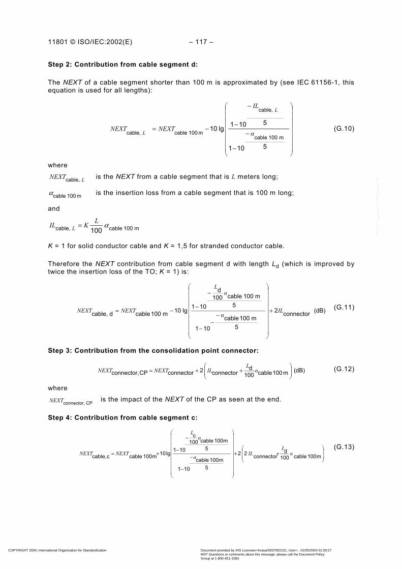
11801 © ISO/IEC:2002(E) – 117 –
Step 2: Contribution from cable segment d:
The NEXT of a cable segment shorter than 100 m is approximated by (see IEC 61156-1, thisequation is used for all lengths):
−
−
−
−−=
5101
5101 lg10m100cable
cable,
m 100cablecable, α
IL
NEXTNEXT
L
L(G.10)
where
LNEXTcable, is the NEXT from a cable segment that is L meters long;
m 100cableα is the insertion loss from a cable segment that is 100 m long;
and
m100cablecable, 100αLKIL L =
K = 1 for solid conductor cable and K = 1,5 for stranded conductor cable.
Therefore the NEXT contribution from cable segment d with length Ld (which is improved bytwice the insertion loss of the TO; K = 1) is:
(dB) connector2
5m100 cable
101
5m100cable100
d
101 lg10m100 cabledcable, ILα
αL
NEXTNEXT +
−−
−
−
−−= (G.11)
Step 3: Contribution from the consolidation point connector:
(dB) m100cable100d
connector2connectorCPconnector,
++= α
LILNEXTNEXT (G.12)
where
CP connector,NEXT is the impact of the NEXT of the CP as seen at the end.
Step 4: Contribution from cable segment c:
++
−
−
−
−+= m100 cable 100d
connector 22
5m100 cable
101
5m100 cable100
c
101 lg10m100 cable c cable, αL
ILα
αL
NEXTNEXT(G.13)
COPYRIGHT 2004; International Organization for Standardization
Document provided by IHS Licensee=Avaya/5937902101, User=, 01/05/2004 01:59:27MST Questions or comments about this message: please call the Document PolicyGroup at 1-800-451-1584.
--``,,`,`````,,,`,,`,`,,````,-`-`,,`,,`,`,,`---

– 118 – 11801 © ISO/IEC:2002(E)
Step 5: Contribution from the floor distributor connector C2:
( )(dB) m100cable100
cdconnector22connectorC2connector,
+++= α
LLILNEXTNEXT (G.14)
where
C2connector,NEXT is the impact of the NEXT of C2 as seen at the end.
Step 6: Add all NEXT contributions from connectors in a voltage sum manner:
++−=
−−−
20
C2connector,
20
CPconnector,
20
TOconnector,
all,connectors10 1010 lg20
NEXTNEXTNEXT
NEXT (G.15)
Step 7: Add all NEXT contributions from cable segments in a power sum manner:
+−=
−−
10
ccable,
10
dcable,
allcable,1010 lg10
NEXTNEXT
NEXT (G.16)
Step 8: Add NEXT contributions from all cable segments and all connectors in a powersum manner:
+−=
−−
10
all,connectors
10
allcable,
TOPL,1010 lg10
NEXTNEXT
NEXT (G.17)
where
TOPL, NEXT is the NEXT of the permanent link, as seen from the TO end.
The same method may be applied for the channel configuration and for all permanent linkconfigurations and from either end.
When the results of this detailed model are compared to the predictions per G.3.2, the simplemodel is found to be 2 dB to 3 dB pessimistic for Class D and Class E channels andpermanent links. This margin is virtually independent of length (for short links the NEXT of thecable is less significant, but the NEXT from far end connectors has more influence; for longerlinks, these conditions are reversed. In a first approximation, these effects offset each other).For Class F links, the detailed predictions are pessimistic for short channels and permanentlinks. Therefore, the pass/fail limits for Class F links may not apply when the total insertionloss is below a threshold value as specified in this standard.
Another consequence of the margin in the computed limits is that cabling components may failtheir individual requirements, and the installed link using such components may still pass theappropriate link requirements.
COPYRIGHT 2004; International Organization for Standardization
Document provided by IHS Licensee=Avaya/5937902101, User=, 01/05/2004 01:59:27MST Questions or comments about this message: please call the Document PolicyGroup at 1-800-451-1584.
--``,,`,`````,,,`,,`,`,,````,-`-`,,`,,`,`,,`---

11801 © ISO/IEC:2002(E) – 119 –
G.3.3.2 Additional assumptions for NEXT
The following assumptions are applicable to the channel and permanent link models forNEXT.
– The power sum addition makes assumptions of statistical independence of sources ofNEXT. There may be some concern that requirements for this assumption are not totallyjustified.
– Excess NEXT contributions that result from unbalanced signals and differential-to-commonand common-to-differential mode coupling are ignored. These can be significant at highfrequencies and when balance properties of the cabling are poor.
– Impact from return loss effects along the various signal routes in the link, is ignored. Thiswill likely be a more serious consideration for Class F cabling. There are phenomena thatdegrade measured performance (excess NEXT from FEXT combined with return losseffects) and others that improve measured performance (NEXT which is reflected backinto the cable).
– In cabling with individually screened wire pairs, the NEXT mechanisms are distinctlydifferent. The crosstalk mechanism involves creating a common mode current in theindividual screens that surround each wire pair, the transfer impedance of that screen anda common-to-differential model conversion into an adjacent wire pair. Common modeterminations highly affect the resulting crosstalk.
G.4 ELFEXT
G.4.1 ELFEXT of the channel configuration
The pass/fail limit for ELFEXT of the channel configuration, for all classes, is computed byadding as a voltage sum the ELFEXT for 100 m cable and four times (4) the FEXT forconnecting hardware as shown in the following formula:
−−
×+−= 20connector
20m 100 cable
CH 10410 lg 20FEXTELFEXT
ELFEXT(G.18)
where
CH ELFEXT is the pass/fail limit for ELFEXT of the channel in dB;
m100 cableELFEXT is the ELFEXT specified for 100 m cable in dB;
connectorFEXT is the FEXT pass/fail limit specified for a single connector in dB.
G.4.2 ELFEXT for the permanent link configurations
The pass/fail limit for ELFEXT of all permanent link configurations, for all class types, equalsthe voltage sum total of the ELFEXT for 100 m cable and three (3) times the FEXT forconnecting hardware as shown in the following equation (FEXT and insertion lossmeasurements are significantly affected by all connectors in the permanent link):
(dB) 10310 lg 20 20connector
20
m100cable
PL
×+−=
−− FEXTELFEXT
ELFEXT (G.19)
where PL ELFEXT is the pass/fail limit for ELFEXT of the permanent link in dB.
COPYRIGHT 2004; International Organization for Standardization
Document provided by IHS Licensee=Avaya/5937902101, User=, 01/05/2004 01:59:27MST Questions or comments about this message: please call the Document PolicyGroup at 1-800-451-1584.
--``,,`,`````,,,`,,`,`,,````,-`-`,,`,,`,`,,`---

– 120 – 11801 © ISO/IEC:2002(E)
G.4.3 Assumptions for ELFEXT
The following assumptions are applicable to the channel and permanent link models forELFEXT:
– ELFEXT of a cable segment depends on its length L by:
−100
lg 10 L (the ELFEXT improves as the cable segment is reduced in length).
– This provides a slight measurement margin for a permanent link:
dB 0,4610090 lg 10 =
− .
– The method to compute channel and permanent link performance is quite precise as allFEXT coupled signals travel approximately the same distance. At high frequencies, delayskew causes phase differences and thereby nulls in the response.
– There is no ELFEXT margin present in channels. However, in practice, the ELFEXT ofcable is generally better than the specified requirements.
– Excess FEXT contributions that may be due to unbalanced signals and the resulting crossmodal crosstalk coupling are ignored.
– Reflected crosstalk and tertiary crosstalk are ignored.– The crosstalk mechanism involves cross-modal crosstalk phenomena. Hence, common
mode terminations affect the crosstalk coupling substantially.
G.5 Return loss
G.5.1 Return loss of the channel and permanent link configurations
Circuit analysis methods must be used for the most accurate prediction of return loss (RL) ofchannel and permanent link configurations from cable and connecting hardwarespecifications. The return loss (RL) of channels and permanent links is obtained by matrixmultiplication of the transmission chain matrices of all components in the channels orpermanent links respectively.
( ) ( )( ) ( )
LL
LL
γγγγ
coshZ
sinhsinhZcosh (G.20)
where
βαγ j+= is the complex propagation constant and Z is the complex characteristicimpedance;
(e) lg 20IL=α
and where
IL is the insertion loss of the component in dB
and e ≅ 2,718 28 (base of natural logarithms).
COPYRIGHT 2004; International Organization for Standardization
Document provided by IHS Licensee=Avaya/5937902101, User=, 01/05/2004 01:59:27MST Questions or comments about this message: please call the Document PolicyGroup at 1-800-451-1584.
--``,,`,`````,,,`,,`,`,,````,-`-`,,`,,`,`,,`---
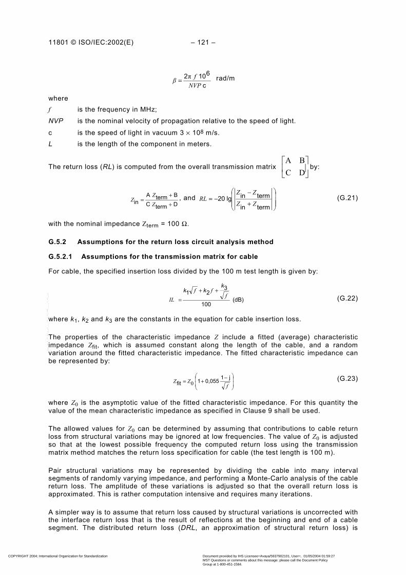
11801 © ISO/IEC:2002(E) – 121 –
c
6102NVP
fβ π= rad/m
wheref is the frequency in MHz;NVP is the nominal velocity of propagation relative to the speed of light.
c is the speed of light in vacuum 3 × 10⁸ m/s.L is the length of the component in meters.
The return loss (RL) is computed from the overall transmission matrix
DCBA
by:
DtermCBtermA
in ++
=ZZ
Z , and
+
−−=
termin
terminlg20ZZ
ZZRL (G.21)
with the nominal impedance Zterm = 100 Ω.
G.5.2 Assumptions for the return loss circuit analysis method
G.5.2.1 Assumptions for the transmission matrix for cable
For cable, the specified insertion loss divided by the 100 m test length is given by:
(dB) 100
321 f
ffIL
kkk ++
= (G.22)
where k1, k2 and k3 are the constants in the equation for cable insertion loss.
The properties of the characteristic impedance Z include a fitted (average) characteristicimpedance Zfit, which is assumed constant along the length of the cable, and a randomvariation around the fitted characteristic impedance. The fitted characteristic impedance canbe represented by:
−+=
fZZ j10,0551fit 0
(G.23)
where Z0 is the asymptotic value of the fitted characteristic impedance. For this quantity thevalue of the mean characteristic impedance as specified in Clause 9 shall be used.
The allowed values for Z0 can be determined by assuming that contributions to cable returnloss from structural variations may be ignored at low frequencies. The value of Z0 is adjustedso that at the lowest possible frequency the computed return loss using the transmissionmatrix method matches the return loss specification for cable (the test length is 100 m).
Pair structural variations may be represented by dividing the cable into many intervalsegments of randomly varying impedance, and performing a Monte-Carlo analysis of the cablereturn loss. The amplitude of these variations is adjusted so that the overall return loss isapproximated. This is rather computation intensive and requires many iterations.
A simpler way is to assume that return loss caused by structural variations is uncorrected withthe interface return loss that is the result of reflections at the beginning and end of a cablesegment. The distributed return loss (DRL, an approximation of structural return loss) is
COPYRIGHT 2004; International Organization for Standardization
Document provided by IHS Licensee=Avaya/5937902101, User=, 01/05/2004 01:59:27MST Questions or comments about this message: please call the Document PolicyGroup at 1-800-451-1584.
--``,,`,`````,,,`,,`,`,,````,-`-`,,`,,`,`,,`---

– 122 – 11801 © ISO/IEC:2002(E)
obtained by power sum subtracting the interface return loss from the specified return loss inthis standard.
−−=
−−
10interface
10cable
1010 lg10
RLRL
DRL (G.24)
DRL at frequencies >50 MHz may be approximated by:
( )fDRL lg10DRL0100m
−= (G.25)
where DRL0 is a constant.
The approximate DRL value of DRL0 is 43,5 dB for Category 5 and Category 6 cable, and48,3 dB for Category 7 cable.
This approximation may be used to represent the contributions from all distributed sources ofreturn loss in cabling for most lengths of cabling. The contribution from DRL over a shortlength of cable may be approximated using the same equation as that used for scaling NEXTper IEC 61156-1. The DRL from all of the cable segments are added together in a power summanner to obtain the DRL for the whole link. Since the DRL contributions from all cablesegments are uncorrected, the same DRL from the previous cable addition can also beobtained directly by assuming the total length in the length dependency equation andcomputing the correction only once. The changes caused by the length dependency equationare minimal when the total length of cabling exceeds 30 m, and therefore one may use theDRL approximation for all practical cabling lengths.
G.5.2.2 Assumptions for the transmission matrix for connectors
For a connector, the product of the propagation delay constant and length L is used.
LLL βαγ j+= (G.26)
For a connector, the propagation constant is calculated according to equation G.26. Themagnitude of the propagation constant is obtained from insertion loss of the connector, andthe phase constant is calculated from the propagation delay at a certain frequency, and isassumed to be proportional to frequency. See equation G.29.
The electrical length Lconnector is obtained from: xf
φNVPL
360xcconnector = (G.27)
where
xφ is the measured phase angle in degrees between the output and input of the connector
at a high frequency xf (for example 100 MHz)
The connector is now modelled as a short transmission line of electrical length Lconnector. Thefrequency response for connector return loss exhibits a 20 dB/decade slope within thefrequency range of interest. The value of the characteristic impedance Zconnector for theconnector is adjusted so that the specified return loss at a certain frequency is matched.Practical values of Lconnector lie between 50 mm and 100 mm. Values of Zconnector liebetween 130 Ω and 150 Ω for a connector with 20 dB @ 100 MHz of return loss.
The insertion loss constant is given by fαL ck= (G.28)
where kc is the constant in the connector insertion loss equation.
COPYRIGHT 2004; International Organization for Standardization
Document provided by IHS Licensee=Avaya/5937902101, User=, 01/05/2004 01:59:27MST Questions or comments about this message: please call the Document PolicyGroup at 1-800-451-1584.
--``,,`,`````,,,`,,`,`,,````,-`-`,,`,,`,`,,`---
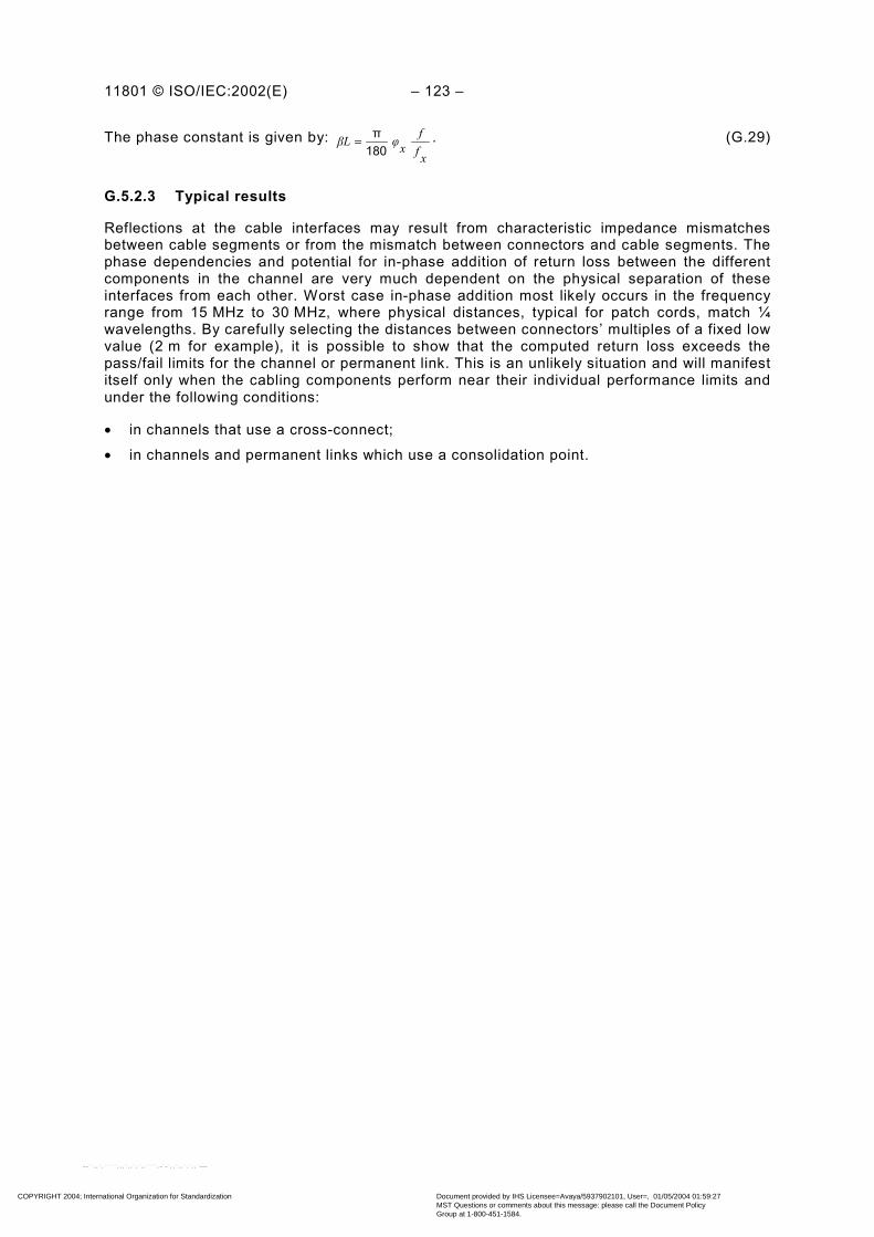
11801 © ISO/IEC:2002(E) – 123 –
The phase constant is given by: xff
xφβL180π= . (G.29)
G.5.2.3 Typical results
Reflections at the cable interfaces may result from characteristic impedance mismatchesbetween cable segments or from the mismatch between connectors and cable segments. Thephase dependencies and potential for in-phase addition of return loss between the differentcomponents in the channel are very much dependent on the physical separation of theseinterfaces from each other. Worst case in-phase addition most likely occurs in the frequencyrange from 15 MHz to 30 MHz, where physical distances, typical for patch cords, match ¼wavelengths. By carefully selecting the distances between connectors’ multiples of a fixed lowvalue (2 m for example), it is possible to show that the computed return loss exceeds thepass/fail limits for the channel or permanent link. This is an unlikely situation and will manifestitself only when the cabling components perform near their individual performance limits andunder the following conditions:
• in channels that use a cross-connect;
• in channels and permanent links which use a consolidation point.
COPYRIGHT 2004; International Organization for Standardization
Document provided by IHS Licensee=Avaya/5937902101, User=, 01/05/2004 01:59:27MST Questions or comments about this message: please call the Document PolicyGroup at 1-800-451-1584.
--``,,`,`````,,,`,,`,`,,````,-`-`,,`,,`,`,,`---

– 124 – 11801 © ISO/IEC:2002(E)
Annex H (informative)
Class F channel and permanent link with two connections
Most class F channels and permanent links are implemented with 2 connections only.
The performance limits for balanced cabling channels given in this annex are derived from thecomponent performance limits of Clauses 9 and 10 assuming the channel is composed of90 m of solid conductor cable, 10 m of cord(s) and two connections (see Figure H.1).
The performance limits for balanced cabling permanent links given in this annex are derivedfrom the component performance limits of Clauses 9 and 10 assuming the permanent link iscomposed of 90 m of solid conductor cable and two connections (see Figure H.1).
TO
FD C
Channel
Permanent link
TE C EQP C C Equipment
cordWork area
cord
C = connection
Figure H.1 – Two connection channel and permanent link
The ACR of each pair combination of a channel and of a permanent link are given in TableH.1.
The PS ACR of each pair of a channel and of a permanent link are also given in Table H.1.
Table H.1 – ACR and PS ACR values for 2 connection class F channels andpermanent links at key frequencies
Channel Permanent linkFrequency
MHzMinimum
ACRdB
MinimumPS ACR
dB
MinimumACRdB
MinimumPS ACR
dB
1 61,0 58,0 61,0 58,0
16 57,1 54,1 58,2 55,2
100 44,6 41,6 47,5 44,5
250 27,3 24,3 31,9 28,9
600 1,1 –1,9 8,6 5,6
COPYRIGHT 2004; International Organization for Standardization
Document provided by IHS Licensee=Avaya/5937902101, User=, 01/05/2004 01:59:27MST Questions or comments about this message: please call the Document PolicyGroup at 1-800-451-1584.
--``,,`,`````,,,`,,`,`,,````,-`-`,,`,,`,`,,`---
11801 © ISO/IEC:2002(E) – 125 –
Annex I (informative)
Significant changes to balanced cabling requirements with respect toearlier editions of this International Standard
I.1 General
This standard contains performance requirements for both components and installed cabling.These requirements differ from those of ISO/IEC 11801 Ed.1 published in 1995, and those ofthe amendments to that edition, consolidated in ISO/IEC 11801 Ed.1.2 (2000).
This informative Annex contains a historical record of these significant technical changes andprovides a reference to the requirements of the earlier editions and amendments of thisstandard.
ISO/IEC 11801 Ed.1 contained requirements for:
– Classes A, B, C and D of installed balanced cabling links and channels.
– 100 Ω (Category 3, 4 and 5) cabling components;
– 120 Ω (Category 3, 4 and 5) cabling components;
– 150 Ω cabling components.
ISO/IEC 11801 Ed.1.2 contained revisions to the requirements for installed cabling (see I.6)but did not include significant changes to the component requirements.
I.2 References
References to this International Standard should specifically differentiate the requirementsand classifications of ISO/IEC 11801 Ed.2 from those of ISO/IEC 11801 Ed.1 (1995) andISO/IEC 11801 Ed.1.2 (2000) (including amendment 1 (1999) and amendment 2 (1999)) byspecifically referencing ISO/IEC 11801 Ed. 2 (2002).
I.3 Structural elements
The TP (transition point), which had no effect on the link and channel performance, has beenremoved and the CP (consolidation point) was introduced. The effects of the CP on the linkand channel performance are taken in account.
I.4 Product designation
For the purpose of component marking and system identification, it is appropriate to directlyreference the year of publication of the second edition, or to use a specific designation thatprovides linkage to it.
I.5 Component requirements
This International Standard contains a revision of the cabling components specified withrespect to their minimum performance as parts of installed links and channels. Specifically,Category 3 (100 Ω and 120 Ω), Category 4 (100 Ω and 120 Ω) and 150 Ω cabling componentshave been removed and Category 6 and 7 requirements have been included.
COPYRIGHT 2004; International Organization for Standardization
Document provided by IHS Licensee=Avaya/5937902101, User=, 01/05/2004 01:59:27MST Questions or comments about this message: please call the Document PolicyGroup at 1-800-451-1584.
--``,,`,`````,,,`,,`,`,,````,-`-`,,`,,`,`,,`---

– 126 – 11801 © ISO/IEC:2002(E)
Specifications for all the cables removed from this standard are included in IEC 61156-2.
Specifications for Category 3 connecting hardware are included in IEC 60603-7 andIEC 60603-7-1 for unscreened and screened components respectively. Specifications forCategory 4 (100 Ω and 120 Ω) connecting hardware are expected to be included inIEC 60603-7-2 and IEC 60603-7-3 for unscreened and screened components respectively.
NOTE 1 At the time of publication IEC 60603-7-2 (Connectors for electronic equipment – Part 7-2: Detailspecification for 8-way, unshielded, free and fixed connectors, for data transmissions with frequencies up to100 MHz) was not available. Until this specification is available compliance to requirements that refer toIEC 60603-7-2 in I.5 may be attained by full compliance with 60603-7, combined with all applicable requirements ofI.5 of this standard.
NOTE 2 At the time of publication IEC 60603-7-3 (Connectors for electronic equipment – Part 7-3: Detailspecification for 8-way, shielded, free and fixed connectors, for data transmissions with frequencies up to100 MHz) was not available. Until this specification is available compliance to requirements that refer toIEC 60603-7-3 in I.5 may be attained by full compliance with 60603-7-1, combined with all applicable requirementsof I.5 of this standard.
Mechanical requirements for 150 Ω connecting hardware are included in IEC 60807-8. Theprincipal transmission performance requirements are included in Table I.1.
Table I.1 - Principal transmission performance requirements of 150 ΩΩΩΩconnecting hardware
Parameter Unit FrequencyMHz Requirement Test method
1,0 0,054,0 0,05
10,0 0,1016,0 0,1520,0 0,15
31,25 0,1562,5 0,20
Maximum attenuation dB
100 0,25
ISO/IEC 11801Ed.1/Ed. 1.2Annex A, A.2.3.1a
1,0 >654,0 >65
10,0 >6516,0 62,420,0 60,5
31,25 56,662,5 50,6
Minimum NEXT dB
100 46,5
ISO/IEC 11801Ed.1/Ed. 1.2Annex A, A.2.3.2a
Minimum return loss dB 1 ≤ f ≤ 100 36 − 20 lg (f/16),26 dB max.
ISO/IEC 11801Ed.1/Ed. 1.2Annex A, A.2.3.2a
a For details, see I1.
NOTE “NEXT loss” was used in previous editions, now “NEXT” is used alone.
I.6 Installed cabling requirements
This International Standard contains modifications to the designations of, and theperformance requirements for installed cabling.
Figure I.1 and Figure I.2 show the installed cabling reference points used inISO/IEC 11801 Ed.1 and ISO/IEC 11801 Ed.1.2 for horizontal and backbone cabling. The link,shown in the figures as “Link (1995)” was defined as the channel excluding the cable withinthe equipment cords. ISO/IEC 11801 Ed.1.2, i.e. amendments 1 and 2 re-defined the
COPYRIGHT 2004; International Organization for Standardization
Document provided by IHS Licensee=Avaya/5937902101, User=, 01/05/2004 01:59:27MST Questions or comments about this message: please call the Document PolicyGroup at 1-800-451-1584.
--``,,`,`````,,,`,,`,`,,````,-`-`,,`,,`,`,,`---

11801 © ISO/IEC:2002(E) – 127 –
reference points as “permanent link” and “channel”. The permanent link was defined as thefixed installation including the connecting hardware at each end.
TO
FD
cc TEEQP c cc
Permanent link
Channel
Link (1995)
c = connection
NOTE Previous editions and amendments of this International Standard do not support the concept of theconsolidation point.
Figure I.1 – Horizontal cabling model
BD or FD
c EQPc c
CD or BD
ccEQP c
Channel
Link (1995)
Permanent link
c = connection
Figure I.2 – Backbone cabling model
In all Tables in this Annex the abbreviations L, PL and C refer to the performance limits forthe classes of “links”, “permanent links” and “channels”, respectively.
Table I.2 to Table I.8 show the requirements for parameters included in bothISO/IEC 11801 Ed.1 and ISO/IEC 11801 Ed.1.2. Component performance requirements forthese parameters, included in ISO/IEC 11801 Ed.1, were not changed inISO/IEC 11801 Ed.1.2, i.e. by amendments 1 and 2.
Table I.9 and Table I.10 show the requirements for parameters included only inISO/IEC 11801 Ed.1.2 (i.e. the amendments). The component performance requirements forthese parameters were not specified in ISO/IEC 11801 Ed.1.2.
The use of components of ISO/IEC 11801 Ed.1 does not imply conformance with therequirements of Table I.9 and Table I.10.
COPYRIGHT 2004; International Organization for Standardization
Document provided by IHS Licensee=Avaya/5937902101, User=, 01/05/2004 01:59:27MST Questions or comments about this message: please call the Document PolicyGroup at 1-800-451-1584.
--``,,`,`````,,,`,,`,`,,````,-`-`,,`,,`,`,,`---
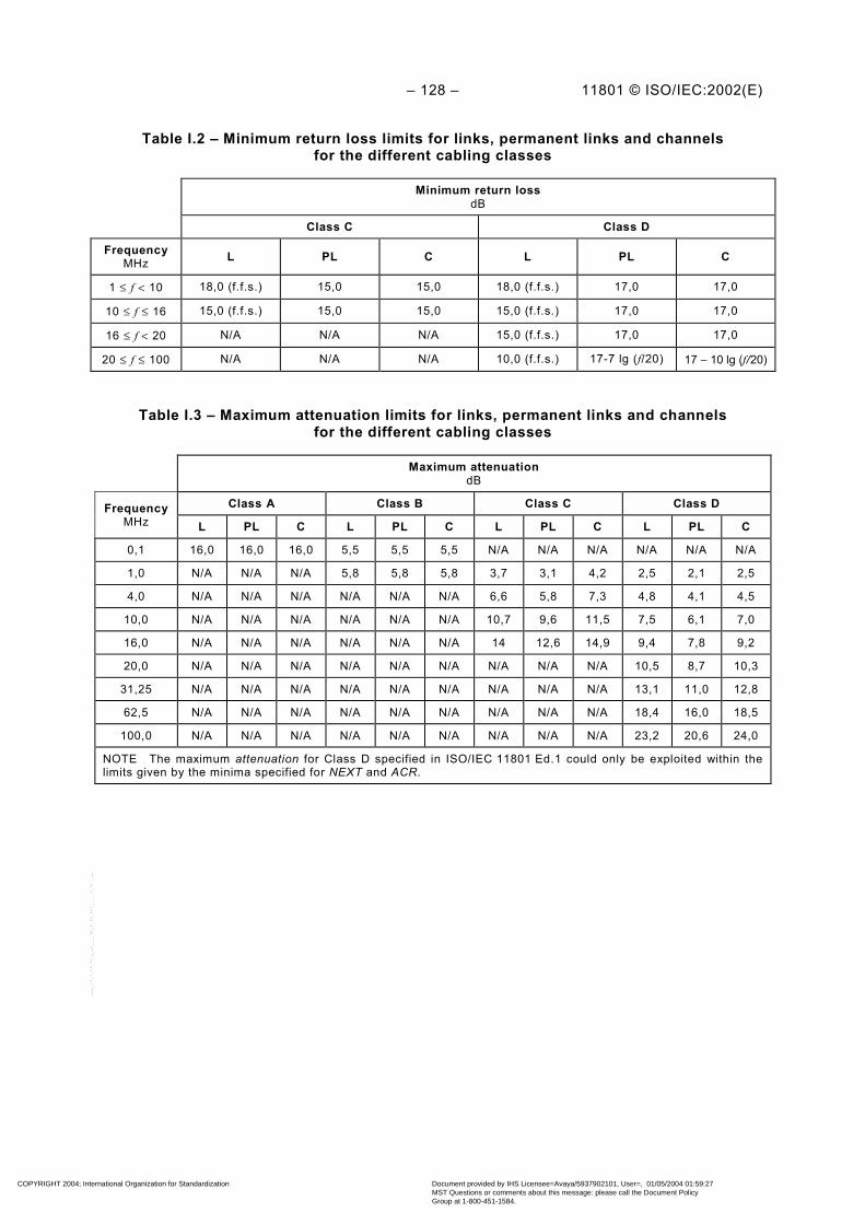
– 128 – 11801 © ISO/IEC:2002(E)
Table I.2 – Minimum return loss limits for links, permanent links and channelsfor the different cabling classes
Minimum return lossdB
Class C Class D
FrequencyMHz L PL C L PL C
1 ≤ f < 10 18,0 (f.f.s.) 15,0 15,0 18,0 (f.f.s.) 17,0 17,0
10 ≤ f ≤ 16 15,0 (f.f.s.) 15,0 15,0 15,0 (f.f.s.) 17,0 17,0
16 ≤ f < 20 N/A N/A N/A 15,0 (f.f.s.) 17,0 17,0
20 ≤ f ≤ 100 N/A N/A N/A 10,0 (f.f.s.) 17-7 lg (f/20) 17 − 10 lg (f/20)
Table I.3 – Maximum attenuation limits for links, permanent links and channelsfor the different cabling classes
Maximum attenuationdB
Class A Class B Class C Class DFrequencyMHz L PL C L PL C L PL C L PL C
0,1 16,0 16,0 16,0 5,5 5,5 5,5 N/A N/A N/A N/A N/A N/A
1,0 N/A N/A N/A 5,8 5,8 5,8 3,7 3,1 4,2 2,5 2,1 2,5
4,0 N/A N/A N/A N/A N/A N/A 6,6 5,8 7,3 4,8 4,1 4,5
10,0 N/A N/A N/A N/A N/A N/A 10,7 9,6 11,5 7,5 6,1 7,0
16,0 N/A N/A N/A N/A N/A N/A 14 12,6 14,9 9,4 7,8 9,2
20,0 N/A N/A N/A N/A N/A N/A N/A N/A N/A 10,5 8,7 10,3
31,25 N/A N/A N/A N/A N/A N/A N/A N/A N/A 13,1 11,0 12,8
62,5 N/A N/A N/A N/A N/A N/A N/A N/A N/A 18,4 16,0 18,5
100,0 N/A N/A N/A N/A N/A N/A N/A N/A N/A 23,2 20,6 24,0
NOTE The maximum attenuation for Class D specified in ISO/IEC 11801 Ed.1 could only be exploited within thelimits given by the minima specified for NEXT and ACR.
COPYRIGHT 2004; International Organization for Standardization
Document provided by IHS Licensee=Avaya/5937902101, User=, 01/05/2004 01:59:27MST Questions or comments about this message: please call the Document PolicyGroup at 1-800-451-1584.
--``,,`,`````,,,`,,`,`,,````,-`-`,,`,,`,`,,`---

11801 © ISO/IEC:2002(E) – 129 –
Table I.4 – Minimum NEXT limits for links, permanent links and channelsfor the different cabling classes
Minimum NEXTdB
Class A Class B Class C Class DFrequencyMHz L PL C L PL C L PL C L PL C
0,1 27,0 27,0 27,0 40,0 40,0 40,0 N/A N/A N/A N/A N/A N/A
1,0 N/A N/A N/A 25,0 25,0 25,0 39,0 40,1 39,1 54,0 61,2 60,3
4,0 N/A N/A N/A N/A N/A N/A 29,0 30,7 29,3 45,0 51,8 50,6
10,0 N/A N/A N/A N/A N/A N/A 23,0 24,3 22,7 39,0 45,5 44,0
16,0 N/A N/A N/A N/A N/A N/A 19,0 21,0 19,3 36,0 42,3 40,6
20,0 N/A N/A N/A N/A N/A N/A N/A N/A N/A 35,0 40,7 39,0
31,25 N/A N/A N/A N/A N/A N/A N/A N/A N/A 32,0 37,6 35,7
62,5 N/A N/A N/A N/A N/A N/A N/A N/A N/A 27,0 32,7 30,6
100,0 N/A N/A N/A N/A N/A N/A N/A N/A N/A 24,0 29,3 27,1
NOTE The minimum NEXT for Class D specified in ISO/IEC 11801 Ed.1 could only be exploited within the limitsgiven by the maxima specified for attenuation and ACR.
Table I.5 – Minimum ACR limits for links, permanent links and channels forthe different cabling classes
Minimum ACRdB
Class A Class B Class C Class DFrequencyMHz L PL C L PL C L PL C L PL C
0,1 11,0 11,0 11,0 34,5 34,5 34,5 – – – – – –
1,0 N/A N/A N/A 19,2 19,2 19,2 35,3 37,0 34,9 - 59,1 57,8
4,0 N/A N/A N/A N/A N/A N/A 22,4 24,9 22,0 40,0 47,7 46,1
10,0 N/A N/A N/A N/A N/A N/A 12,3 14,7 11,2 35,0 39,4 37,0
16,0 N/A N/A N/A N/A N/A N/A 5,0 8,4 4,4 30,0 34,5 31,4
20,0 N/A N/A N/A N/A N/A N/A N/A N/A N/A 28,0 32,0 28,7
31,25 N/A N/A N/A N/A N/A N/A N/A N/A N/A 23,0 26,6 22,9
62,5 N/A N/A N/A N/A N/A N/A N/A N/A N/A 13,0 16,7 12,1
100,0 N/A N/A N/A N/A N/A N/A N/A N/A N/A 4,0 8,7 3,1
NOTE 1 The return loss requirements of ISO/IEC 11801 Ed.1 and ISO/IEC 11801 Ed.1.2, i.e. the amendments,demand that the links, permanent links and channels under test be terminated with an impedance equal to that ofthe design impedance of the cabling (100 Ω, 120 Ω or 150 Ω as applicable). The test methods referred to inISO/IEC 11801 Ed.2 require that cabling be terminated with an impedance of 100 Ω only.
NOTE 2 The ACR for Class D specified in ISO/IEC 11801 Ed.1 provided some head room for trade off betweenNEXT and attenuation.
COPYRIGHT 2004; International Organization for Standardization
Document provided by IHS Licensee=Avaya/5937902101, User=, 01/05/2004 01:59:27MST Questions or comments about this message: please call the Document PolicyGroup at 1-800-451-1584.
--``,,`,`````,,,`,,`,`,,````,-`-`,,`,,`,`,,`---

– 130 – 11801 © ISO/IEC:2002(E)
Table I.6 – Maximum propagation delay limits for links, permanent links andchannels for the different cabling classes
L PL C
Class FrequencyMHz
Maximum delayµs
FrequencyMHz
Maximum delayµs
FrequencyMHz
Maximum delayµs
A 0,01 20,0 a 0,1 0,9 0,1 20,0 a
B 1,0 5,0 a 1,0 0,9 1,0 5,0 a
C 10,0 1,0 1 ≤ f ≤16 0,486+0,036/√f 1 ≤ f ≤16 0,544+0,036/√f
D 30,0 1,0 1 ≤ f ≤ 100 0,486+0,036/√f 1 ≤ f ≤ 100 0,544+0,036/√fa The maximum delay within horizontal generic links and channels = 1,0 µs.
Table I.7 – Maximum d.c. loop resistance limits for links, permanent links andchannels for the different cabling classes
Maximum d.c. loop resistanceΩ
Class A Class B Class C Class D
L PL C L PL C L PL C L PL C
560 560 560 170 170 170 40 40 40 40 40 40
The term “unbalance attenuation” was not used in ISO/IEC 11801 Ed.1 and ISO/IEC 11801Ed.1.2, i.e. the amendments 1 or 2. Instead “longitudinal to differential conversion loss(balance) measured as LCL and as LCTL according to ITU-T Recommendation G.117” wasspecified and the requirements are shown in Table I.8.
Table I.8 – Minimum unbalance attenuation (LCL/LCTL) limits for links, permanent linksand channels for the different cabling classes
Minimum LCL/LCTLdB
Class A Class B Class C Class DFrequencyMHz L PL C L PL C L PL C L PL C
0,1 30 30 30 45 45 45 35 45 45 40 45 45
1,0 N/A N/A N/A 20 20 20 30 30 30 40 40 40
4,0 N/A N/A N/A N/A N/A N/A f.f.s. f.f.s. f.f.s. f.f.s. f.f.s. f.f.s.
10,0 N/A N/A N/A N/A N/A N/A 25 25 25 30 30 30
16,0 N/A N/A N/A N/A N/A N/A f.f.s. f.f.s. f.f.s. f.f.s. f.f.s. f.f.s.
20,0 N/A N/A N/A N/A N/A N/A f.f.s. f.f.s. f.f.s. f.f.s. f.f.s. f.f.s.
100,0 N/A N/A N/A N/A N/A N/A N/A N/A N/A f.f.s. f.f.s. f.f.s.
COPYRIGHT 2004; International Organization for Standardization
Document provided by IHS Licensee=Avaya/5937902101, User=, 01/05/2004 01:59:27MST Questions or comments about this message: please call the Document PolicyGroup at 1-800-451-1584.
--``,,`,`````,,,`,,`,`,,````,-`-`,,`,,`,`,,`---

11801 © ISO/IEC:2002(E) – 131 –
Table I.9 – Minimum PS NEXT, PS ACR, ELFEXT and PS ELFEXT limits forpermanent links and channels for the different cabling classes
MinimumPS NEXT
dB
MinimumPS ACR
dB
MinimumELFEXT
dB
MinimumPS ELFEXT
dB
Class D Class D Class D Class DFrequencyMHz PL C PL C PL C PL C
1,0 58,2 57,3 56,1 54,8 59,6 57,0 57,0 54,4
4,0 48,8 47,6 44,7 43,1 47,6 45,0 45,0 42,6
10,0 42,5 41,0 36,4 34,0 39,6 37,0 37,0 34,4
16,0 39,3 37,6 31,5 28,4 35,5 32,9 32,9 30,3
20,0 37,7 36,0 29,0 25,7 33,6 31,0 31,0 28,4
31,25 34,6 32,7 23,6 19,9 29,7 27,0 27,1 24,5
62,5 29,7 27,6 13,7 9,1 23,7 21,1 21,1 18,5
100,0 26,3 24,1 5,7 0,1 19,6 17,0 17,0 14,4
NOTE Limits for power sum parameters were not included in ISO/IEC 11801Ed.1.
Table I.10 – Maximum delay skew limits for permanent links and channelsfor the different cabling classes
Maximum delay skewµs
Class A Class B Class C Class DFrequencyMHz PL C PL C PL C PL C
1 ≤ f ≤16 N/A N/A N/A N/A 0,043 0,050 0,043 0,050
1 ≤ f ≤ 100 N/A N/A N/A N/A 0,043 0,050 0,043 0,050
NOTE Limits for delay skew were not included in ISO/IEC 11801 Ed.1.
COPYRIGHT 2004; International Organization for Standardization
Document provided by IHS Licensee=Avaya/5937902101, User=, 01/05/2004 01:59:27MST Questions or comments about this message: please call the Document PolicyGroup at 1-800-451-1584.
--``,,`,`````,,,`,,`,`,,````,-`-`,,`,,`,`,,`---

– 132 – 11801 © ISO/IEC:2002(E)
Bibliography
CISPR 22, Information technology equipment – Radio disturbance characteristics – Limits andmethods of measurement
CISPR 24, Information technology equipment - Immunity characteristics – Limits and methodsof measurement
IEC 60068-2-2, Basic environmental testing procedures – Part 2: Tests – Tests B: Dry heat
IEC 60068-2-6, Environmental testing – Part 2: Tests – Tests Fc: Vibration (sinusoidal)
IEC 60068-2-60, Environmental testing – Part 2: Tests – Test Ke: Flowing mixed gascorrosion test
IEC 60096-1, Radio-frequency cables – Part 1: General requirements and measuring methods
IEC 60189-1, Low-frequency cables and wires with p.v.c. insulation and p.v.c. sheath –Part 1: General test and measuring methods
IEC 60227-2, Polyvinyl chloride insulated cables of rated voltages up to and including450/750 V – Part 2: Test methods
IEC 60332-3 (all parts), Tests on electric cables under fire conditions – Part 3: Test forvertical flame spread on vertically-mounted bunched wires or cables
IEC 60512 (all parts), Connectors for electronic equipment – Tests and measurements
IEC 60512-1, Connectors for electronic equipment – Tests and measurements –Part 1: General
IEC 60512-3:1976, Electromechanical components for electronic equipment – Basic testingprocedures and measuring methods – Part 3: Current-carrying capacity tests
IEC 60512-25-3, Connectors for electronic equipment – Tests and measurements – Part 25-3:Test 25c – Rise time degradation
IEC 60708-1, Low-frequency cables with polyolefin insulation and moisture barrier polyolefinsheath – Part 1: General design details and requirements
IEC 60793-1 (all parts), Optical fibres – Part 1: Generic specification
IEC 60793-1-4X (all parts), Optical fibres – Part 1-4X: Measurement methods and testprocedures
IEC 60794-1 (all parts), Optical fibre cables – Part 1: Generic specification
IEC 60794-1-1, Optical fibre cables – Part 1-1: Generic specification – General
IEC 60794-1-2, Optical fibre cables – Part 1-2: Generic specification – Basic optical cable testprocedures
IEC 60807-8, Rectangular connectors for frequencies below 3 MHz – Part 8: Detailspecification for connectors, four-signal contacts and earthing contacts for cable screen
COPYRIGHT 2004; International Organization for Standardization
Document provided by IHS Licensee=Avaya/5937902101, User=, 01/05/2004 01:59:27MST Questions or comments about this message: please call the Document PolicyGroup at 1-800-451-1584.
--``,,`,`````,,,`,,`,`,,````,-`-`,,`,,`,`,,`---

11801 © ISO/IEC:2002(E) – 133 –
IEC 60811-1-1, Common test methods for insulating and sheathing materials of electriccables – Part 1-1: Methods for general application – Measurement of thickness and overalldimensions – Tests for determining the mechanical properties
IEC 60825-1, Safety of laser products – Part 1: Equipment classification, requirements anduser's guide
IEC 60874-10, Connectors for optical fibres and cables – Part 10: Sectional specification forfibre optic connector – Type BFOC/2,5
IEC 60874-19-4, Connectors for optical fibres and cables – Part 19-4: Detail specification forfibre optic connector (duplex) type SC-PC premium for multi-mode fibre type A1a, A1b(Under consideration)
IEC 60874-19-5, Connectors for optical fibres and cables – Part 19-5: Detail specification forfibre optic connector Type SC-PC (Rigid Duplex) Standard for multimode fibre type A1a, A1b(Under consideration)
IEC 60950 (all parts), Information technology equipment – Safety
IEC 61000-2-2, Electromagnetic compatibility (EMC) – Part 2-2: Environment – Compatibilitylevels for low-frequency conducted disturbances and signalling in public low-voltage powersupply systems
IEC/TR3 61000-5-2:1997, Electromagnetic compatibility (EMC) – Part 5: Installation andmitigation guidelines – Section 2: Earthing and cabling
IEC 61000-5-2, Electromagnetic compatibility (EMC) – Part 5-2: Installation and mitigationguidelines – Earthing and bonding (Under consideration)
IEC 61035-1, Specification for conduit fittings for electrical installations – Part 1: Generalrequirements
IEC 61076-3-104, Connectors for electronic equipment – Part 3-104: Detail specification for 8-way, shielded free and fixed connectors, for data transmissions with frequencies up to600 MHz (Under consideration)
IEC 61280 (all parts), Fibre optic communication subsystem basic test procedures
IEC 61280-4-1, Fibre optic communication subsystem basic test procedures – Part 4-1: Testprocedures for fibre optic cable plant and links – Multimode fibre optic plant attenuationmeasurement
IEC 61280-4-2:1999, Fibre optic communication subsystem basic test procedure – Part 4-2:Fibre optic cable plant – Single-mode fibre optic plant attenuation measurement
IEC 61280-4-3, Fibre optic communication subsystem basic test procedure – Part 4-3: Fibreoptic cable plant – Single-mode fibre optic plant optical return loss measurement
IEC 61300 (all parts), Fibre optic interconnecting devices and passive components – Basictest and measurement procedures
IEC 61300-2-1, Fibre optic interconnecting devices and passive components – Basic test andmeasurement procedures – Part 2-1: Tests – Vibration (sinusoidal)
IEC 61300-2-4, Fibre optic interconnecting devices and passive components – Basic test andmeasurement procedures – Part 2-4: Tests – Fibre/cable retention
COPYRIGHT 2004; International Organization for Standardization
Document provided by IHS Licensee=Avaya/5937902101, User=, 01/05/2004 01:59:27MST Questions or comments about this message: please call the Document PolicyGroup at 1-800-451-1584.
--``,,`,`````,,,`,,`,`,,````,-`-`,,`,,`,`,,`---

– 134 – 11801 © ISO/IEC:2002(E)
IEC 61300-2-5, Fibre optic interconnecting devices and passive components – Basic test andmeasurement procedures – Part 2-5: Tests – Torsion/twist
IEC 61300-2-6, Fibre optic interconnecting devices and passive components – Basic test andmeasurement procedures – Part 2-6: Tests – Tensile strength of coupling mechanism
IEC 61300-2-12, Fibre optic interconnecting devices and passive components – Basic testand measurement procedures – Part 2-12: Tests – Impact
IEC 61300-2-17, Fibre optic interconnecting devices and passive components – Basic testand measurement procedures – Part 2-17: Tests – Cold
IEC 61300-2-18, Fibre optic interconnecting devices and passive components – Basic testand measurement procedures – Part 2-18: Tests – Dry heat – High temperature endurance
IEC 61300-2-19, Fibre optic interconnecting devices and passive components – Basic testand measurement procedures – Part 2-19: Tests – Damp heat (steady state)
IEC 61300-2-22, Fibre optic interconnecting devices and passive components – Basic testand measurement procedures – Part 2-22: Tests – Change of temperature
IEC 61300-2-42, Fibre optic interconnecting devices and passive components – Basic testand measurement procedures – Part 2-42: Tests – Static side load for connectors
ISO/IEC 8802-3, Information technology – Telecommunications and information exchangebetween systems – Local and metropolitan area networks – Specific requirements – Part 3:Carrier sense multiple access with collision detection (CSMA/CD) access method andphysical layer specifications
ISO/IEC 8802-4, Information processing systems – Local area networks – Part 4: Token-passing bus access method and physical layer specifications
ISO/IEC 8802-5, Information technology – Telecommunications and information exchangebetween systems – Local and metropolitan area networks – Specific requirements – Part 5:Token ring access method and physical layer specifications
ISO/IEC 8802-9, Information technology – Telecommunications and information exchangebetween systems – Local and metropolitan area networks – Specific requirements – Part 9:Integrated Services (IS) LAN Interface at the Medium Access Control (MAC) and Physical(PHY) Layers
ISO/IEC 8802-12, Information technology – Telecommunications and information exchangebetween systems – Local and metropolitan area networks – Specific requirements – Part 12:Demand-Priority access method, physical layer and repeater specifications
COPYRIGHT 2004; International Organization for Standardization
Document provided by IHS Licensee=Avaya/5937902101, User=, 01/05/2004 01:59:27MST Questions or comments about this message: please call the Document PolicyGroup at 1-800-451-1584.
--``,,`,`````,,,`,,`,`,,````,-`-`,,`,,`,`,,`---

11801 © ISO/IEC:2002(E) – 135 –
ISO/IEC 8877, Information technology – Telecommunications and information exchangebetween systems – Interface connector and contact assignment for ISDN Basic AccessInterface located at reference points S and T
ISO/IEC 9314-3, Information processing systems – Fibre Distributed Data Interface (FDDI) –Part 3: Physical Layer Medium Dependent (PMD)
ISO/IEC 9314-4, Information technology – Fibre Distributed Data Interface (FDDI) – Part 4:Single Mode Fibre Physical Layer Medium Dependent (SMF-PMD)
ISO/IEC 9314-9, Information technology – Fibre Distributed Data Interface (FDDI) – Part 9:Low-cost Fibre, Physical Layer Medium Dependent (LCF-PMD)
ISO/IEC 9314-10, Information technology – Fibre Distributed Data Interface (FDDI) – Part 10:Twisted pair physical layer medium dependent (TP-PMD) (Under consideration)
ISO/IEC 11518-1, Information technology – High-performance Parallel Interface – Part 1:Mechanical, electrical and signalling protocol specification (HIPPI-PH)
ISO/IEC/TR2 11802-4:1994, Information technology – Telecommunications and informationexchange between systems – Technical reports and guidelines – Part 4: Token ring accessmethod and physical layer specifications – Fibre optic attachment
ISO/IEC/TR 12075, Information technology – Customer premises cabling – Planning andinstallation guide to support ISO/IEC 8802-5 token ring stations
ISO/IEC 14165-111, Information technology – Fibre channel – Part 111: Physical andsignalling interface (Under consideration)
ISO/IEC 14165-114, Information technology – Fibre channel – Part 114: 100 Mbyte/s Twistedpair physical interface (Under consideration)
ISO/IEC 14709 (all parts), Information technology – Configuration of Customer PremisesCabling (CPC) for applications
ISO/IEC 14709-1, Information technology – Configuration of Customer Premises Cabling(CPC) for applications – Part 1: Integrated Services Digital Network (ISDN) basic access
ISO/IEC 14709-2, Information technology – Configuration of Customer Premises Cabling(CPC) for applications – Part 2: Integrated Services Digital Network (ISDN) primary rate
ISO/IEC 15018, Information technology – Integrated cabling for residential and SOHO (SmallOffice Home Office) environments (Under consideration)
ITU-T Rec. G.117, Transmission aspects of unbalance about earth
ITU-T Rec. I.430, Basic user-network interface; Layer 1 specification
ITU-T Rec. I.431, Primary rate user-network interface; Layer 1 specification
ITU-T Rec. I.432, B-ISDN user network interface; physical layer specification
ITU-T Rec. G.650, Transmission media characteristics – Definition and test methods for therelevant parameters of single-mode fibres
COPYRIGHT 2004; International Organization for Standardization
Document provided by IHS Licensee=Avaya/5937902101, User=, 01/05/2004 01:59:27MST Questions or comments about this message: please call the Document PolicyGroup at 1-800-451-1584.
--``,,`,`````,,,`,,`,`,,````,-`-`,,`,,`,`,,`---

– 136 – 11801 © ISO/IEC:2002(E)
ITU-T Rec. G.651, Characteristics of a 50/125 µm multimode graded index optical fibre cable
ITU-T Rec O.9, Measuring arrangements to assess the degree of unbalance about earth
ITU-T Rec. V.11, Electrical characteristics for balanced double-current interchange circuits forgeneral use with integrated circuit equipment in the field of data communications
ITU-T Rec. X.21, Interface between data terminal equipment (DTE) and data circuit-terminating equipment (DCE) for synchronous operation on public data networks
–––––––––––––––––
COPYRIGHT 2004; International Organization for Standardization
Document provided by IHS Licensee=Avaya/5937902101, User=, 01/05/2004 01:59:27MST Questions or comments about this message: please call the Document PolicyGroup at 1-800-451-1584.
--``,,`,`````,,,`,,`,`,,````,-`-`,,`,,`,`,,`---

COPYRIGHT 2004; International Organization for Standardization
Document provided by IHS Licensee=Avaya/5937902101, User=, 01/05/2004 01:59:27MST Questions or comments about this message: please call the Document PolicyGroup at 1-800-451-1584.
--``,,`,`````,,,`,,`,`,,````,-`-`,,`,,`,`,,`---

ISBN 2-8318-6575-1
-:HSMINB=][Z\ZV:ICS 35.200
Typeset and printed by the IEC Central OfficeGENEVA, SWITZERLAND
COPYRIGHT 2004; International Organization for Standardization
Document provided by IHS Licensee=Avaya/5937902101, User=, 01/05/2004 01:59:27MST Questions or comments about this message: please call the Document PolicyGroup at 1-800-451-1584.
--``,,`,`````,,,`,,`,`,,````,-`-`,,`,,`,`,,`---