international journal for research in engineering ...ijream.org/papers/ijreamv04i0541135.pdf ·...
TRANSCRIPT

International Journal for Research in Engineering Application & Management (IJREAM)
ISSN : 2454-9150 Vol-04, Issue-05, Aug 2018
555 | IJREAMV04I0541135 DOI : 10.18231/2454-9150.2018.0673 © 2018, IJREAM All Rights Reserved.
Automation in Ansys APDL Simulating Square Plate
with a Circular Hole Afreen, Master of Engineering, Sankethika Vidhya Parishad Engineering College, Vishakapatnam
& India, [email protected]
Ch. Bhanu Sree, Assistant Professor, Sankethika Vidhya Parishad Engineering College,
Vishakapatnam & India, [email protected]
Abstract: Now-a-days, AUTOMATION is improving at faster rates in our nation. Advantages commonly attributed to
automation include higher production rates and increased productivity, more efficient use of materials, better product
quality, improved safety, shorter work weeks for labor, and reduced factory lead times. Hence, the present work is
introducing automation (programming in ANSYS APDL) in finding out stress concentration factors for rectangular or
square plate with a circular hole at ANY LOCATION, also tested the same specimen with two materials – Structural
Steel and Aluminum 6061-T6. The plate mentioned is subjected to uniform tensile load. The stress concentration factor
has been calculated by using both analytical and finite element methods. By using this automation tool, a researcher
can directly get SCF (stress concentration factor) for different materials in a very less time and can reduced R&D lead
times.
Keywords — Ansys, APDL, Automation, Stress concentration factor, Finite Element Analysis
I. INTRODUCTION
Structural integrity is very crucial in all mechanical
industries like Aerospace, Automobiles, Oil & Gas, and
Power Sectors. As per codes and standards all the designing
and execution works will carry out, for safety and quality.
But the common structure that comes across in all types of
industries is a plate with hole appears as a single part or in
assemblies. Evaluating stress concentrations at the location
where material has been removed like holes or notches is a
standard practice followed before selection of material of
construction (MOC).
Hence in this project a Square plate with a circular hole in
it is considered with different materials, which is subjected
to normal tensile load (bi-axially). Manually if done this
project in ANSYS – Pre-processing, Solve and Post-
processing will take atleast 30 to 50 minutes from an expert
level to beginner level. Instead of that, this project has
contributed its time in develop a program/code to complete
this task in milliseconds, with Graphic User Interface and
User Customization for geometry changes has also been
added in this MACRO, which saves not only time, but also
money in research point of view.
II. ANALYSIS OF SPWCH (SQUARE PLATE
WITH A CIRCULAR HOLE) – MANUALLY
Following are the detailed step-by-step procedure for
modeling a square plate with circular hole at center.
Since this part is symmetric in both „X‟ and „Y‟ axes, we
can model quarter of the part and give symmetric boundary
conditions, so that it will save time and also reduces
number of finite element equations to solve.
Step-1: Defining preferences as “Structural”
Step-2: Choose “8 Node 183” for Element Type
Step-3: After selecting the element type, click on “Options”
button and select Element Behavior (K3) as “Plane strs
w/thk”, which says that the thickness can be added for
element directly.
Step-4: Now go with the Real Constants and define
Thickness (THK) = 2
Step-5: As shown go to Material Model and enter the
mechanical properties of the material being considered for
analysis.
Step-6: Geometry Modeling starts with defining Key
points. The Square plate which is considered has
dimensions as, L X B X T = 100 X 100 X 2 (mm). As
shown in the figures below, define key points accordingly.
Step-7: Now creating lines and arc for the geometry. As
shown in below figure, select “By End KPs & Radius”
option. In the first go, select key points – „2‟ and „6‟, then
click on “Apply” button, again it prompts to pick the center
of the curvature, then select key point „1‟, now a window
will appear and prompts for “RAD” value, enter 5 and
“OK”.
Step-8: Now an arc has created between key points „2‟ and
„6‟, with 5mm radius.
Step-9: Create lines using “In Active Coord” option and
select each point.
Step-10: “Mesh Tool” has used to mesh lines for manually
setting the Number of Element Divisions (NDIV) and
Spacing Ratio (SPACE) between the elements (a.k.a
Biasing)

International Journal for Research in Engineering Application & Management (IJREAM)
ISSN : 2454-9150 Vol-04, Issue-05, Aug 2018
556 | IJREAMV04I0541135 DOI : 10.18231/2454-9150.2018.0673 © 2018, IJREAM All Rights Reserved.
For Line „L1‟ NDIV = 30; For Line „L2‟ and „L5‟ NDIV =
15 also SPACE = 8
For „L3‟ and „L4‟ NDIV = 15
Step-11: Create area using the lines (L1 to L6) including
the arc.
Step-12: Concatenate lines „L3‟ and „L4‟, so that mapped
meshing can be possible
Step-13: Again use Mesh Tool to mesh the area created.
Make sure that “Mapped” option was selected and choose
the area.
Step-14: Applying boundary conditions. First, define
SYMMETRY B.C. as shown.
Step-15: Plot only lines to see the symmetry symbol “s” on
the lines considered.
Step-16: The tensile force which has to be applied on the
plate must be distributed on all nodes existing on line „L3‟.
For this to happen, choose “Coupling/Ceqn” and select all
nodes using BOX option.
Step-17: After selection of all nodes a window appears and
prompts to set reference number (NSET) – any number can
be entered; choose “UX” for “Degree-of-freedom label” as
the tensile force/load is going to be in X-direction only.
Step-18: Applying force. Select any node on the line „L3‟,
the force will distribute with equal share on each node.
Direction of force/mom = “FX”
VALUE = 500
As this is a symmetry design, the total force applied is
1000N
III. SOLUTION
Step-1: Go to plot results and select “Deformed Shape” =
„Def + undef shape‟
Maximum Displacement obtained in X-direction, DMX =
0.127e-08 mm
Step-2: Plot Results > Contour Plot > Nodal Solu> Stress >
Von Mises Stress
Maximum Stress obtained in X-direction, SMX = 14.74
MPa
Step-3: To see full portion of the entire plate.
Go to, PlotCtrls> Style > Symmetry Expansion >
Periodic/Cyclic Symmetry > select type of cyclic symmetry
as “1/4 Dihedral Sym”
Fig:3.1 Deformed Shape of SPWCH – Quarter part
Fig: 3.2 Von-mises Stress for the entire plate
From ANSYS APDL main window access File > Read
Input From… > Choose the TXT file which was saved in
the previous procedure. A window will appear, prompting
the required input to do the analysis.
Fig:3.3 Graphic-User-Interface of the Developed Macro Inputs
Fig:3.4 Actual meaning of the variables used in Macro
Units
Inputs in the macro are
Length of the plate, L = 100 mm
Height of the plate, H = 100 mm
Vertical distance from top of the plate to hole center, A =
50 mm
Horizontal distance from edge of the plate to hole center, B
= 50 mm
Hole radius, R = 5 mm
Plate thickness, CURTHICK = 2 mm
Modulus of Elasticity, YM = 210 GPa (210e9)
Poisson‟s Ratio, MU = 0.3
Force Applied, F = 1000 N
Enter the above values and click “OK”
“Solution is done!” - Exactly within 54 seconds.
Values entered at 19:03:43 and Solution done at 19:04:47,
International Journal for Research in Engineering Application & Management (IJREAM)
ISSN : 2454-9150 Vol-04, Issue-05, Aug 2018
557 | IJREAMV04I0541135 DOI : 10.18231/2454-9150.2018.0673 © 2018, IJREAM All Rights Reserved.
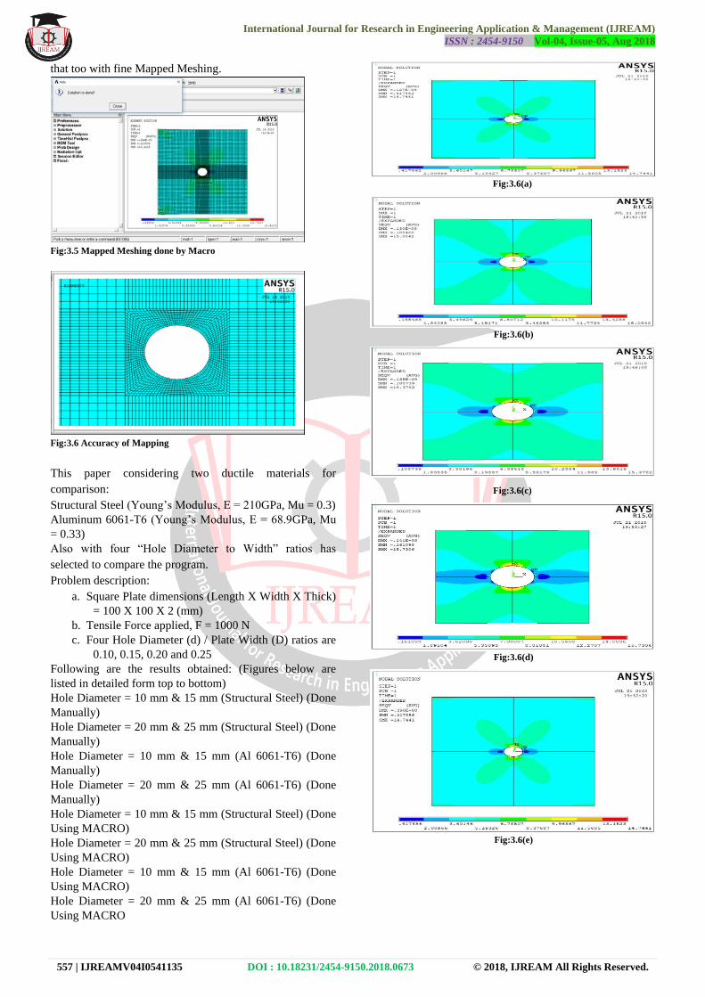
that too with fine Mapped Meshing.
Fig:3.5 Mapped Meshing done by Macro
Fig:3.6 Accuracy of Mapping
This paper considering two ductile materials for
comparison:
Structural Steel (Young‟s Modulus, E = 210GPa, Mu = 0.3)
Aluminum 6061-T6 (Young‟s Modulus, E = 68.9GPa, Mu
= 0.33)
Also with four “Hole Diameter to Width” ratios has
selected to compare the program.
Problem description:
a. Square Plate dimensions (Length X Width X Thick)
= 100 X 100 X 2 (mm)
b. Tensile Force applied, F = 1000 N
c. Four Hole Diameter (d) / Plate Width (D) ratios are
0.10, 0.15, 0.20 and 0.25
Following are the results obtained: (Figures below are
listed in detailed form top to bottom)
Hole Diameter = 10 mm & 15 mm (Structural Steel) (Done
Manually)
Hole Diameter = 20 mm & 25 mm (Structural Steel) (Done
Manually)
Hole Diameter = 10 mm & 15 mm (Al 6061-T6) (Done
Manually)
Hole Diameter = 20 mm & 25 mm (Al 6061-T6) (Done
Manually)
Hole Diameter = 10 mm & 15 mm (Structural Steel) (Done
Using MACRO)
Hole Diameter = 20 mm & 25 mm (Structural Steel) (Done
Using MACRO)
Hole Diameter = 10 mm & 15 mm (Al 6061-T6) (Done
Using MACRO)
Hole Diameter = 20 mm & 25 mm (Al 6061-T6) (Done
Using MACRO
Fig:3.6(a)
Fig:3.6(b)
Fig:3.6(c)
Fig:3.6(d)
Fig:3.6(e)

International Journal for Research in Engineering Application & Management (IJREAM)
ISSN : 2454-9150 Vol-04, Issue-05, Aug 2018
558 | IJREAMV04I0541135 DOI : 10.18231/2454-9150.2018.0673 © 2018, IJREAM All Rights Reserved.
Fig:3.6(f)
Fig:3.6(g)
Fig:3.6(h)
Fig:3.6(i)
Fig:3.6(j)
Fig:3.6(k)
Fig:3.6(l)
Fig:3.6(m)

International Journal for Research in Engineering Application & Management (IJREAM)
ISSN : 2454-9150 Vol-04, Issue-05, Aug 2018
559 | IJREAMV04I0541135 DOI : 10.18231/2454-9150.2018.0673 © 2018, IJREAM All Rights Reserved.
Fig:3.6(n)
Fig:3.6(o)
Fig:3.6(p)
IV. RESULTS COMPARISION,VALIDATION
AND PERCENTAGE ERROR CHECKING
Before that all the theoretical formulae which has been used
to calculate and compare are shown below:
Stress concentration factor, Kt for a circular hole = 3,
generally
Nominal Stress,
Nominal Stress,
Stress Concentration Factor from Stresses,
Stress Concentration Factor from Diameter to Width
Ratios,
Percentage Error,
Table:4.1 Respective Values of d/D Ratio and Kt
Table:4.2 Nominal, Max. - Stresses & Kt Obtained in ANSYS using
MANUAL & MACRO usage
Table:4.3 Stress Concentration Factor, Kt % Error Check

International Journal for Research in Engineering Application & Management (IJREAM)
ISSN : 2454-9150 Vol-04, Issue-05, Aug 2018
560 | IJREAMV04I0541135 DOI : 10.18231/2454-9150.2018.0673 © 2018, IJREAM All Rights Reserved.
Table:4.4 Max. Stress % Error Check
Since this macro is developed with a motivation that the
circular hole can be anywhere inside the plate, not only at
the center. If an engineer has to do analysis for an
unsymmetrical location of hole in a square plate, he/she has
to model and analyze in full portion and there is no chance
to consider quarter portion. Thus at those situations this
MACRO can help them.
V. CONCLUSION
From the present investigation, it can be concluded that the
maximum stress occurs at corners of holes in both
materials. Also, for both materials, while an increase in T/D
ratio resulted into a decrease in Von-Mises stress and as
T/D ratio increases with increase in stress concentration
factor. The stress concentration factor values obtained from
finite element analysis shows a maximum error of 2.51%
for Manual analysis and 5.05 for Macro analysis –
Structural Steel and also shows a maximum error of 2.51%
for Manual analysis and 5.17 for Macro analysis –
Aluminum 6061-T6 which are acceptable. Thus, from the
present study, it can be said that finite element analysis is a
very effective tool to determine stresses induced in various
materials.
Even though the experiment of tensile test on a plate with a
hole in it is very simple one, but it has enormous technical
challenges which have not been relieved yet. If for different
materials this same experiment has to run, then the entire
pre-processing process has to be changed and re-run the
analysis. If in another case the hole which is at center has
to be in another location, except center, then the entire
modeling work and then the pre & post works has to be
carried out newly. With this macro, the mentioned
challenges can be solved very easily and at rocket speeds.
VI. FUTURE SCOPE
This macro developed for square plate alone. In future it
can be upgraded to work for rectangular plates also with
holes with different geometry like circular, box type,
rhombus shape etc. Also same procedure can be followed
to develop macros that can work for plates with notches.
Forecasting also is in progress for composite materials.
ACKNOWLEDGMENT
The preferred spelling of the word “acknowledgment” in
American English is without an “e” after the “g.” Use the
singular heading even if you have many acknowledgments.
REFERENCES
[1] Ulku Babuscu Yesil,“The effect of the initial stretching
of the rectangular plate with a cylindrical hole on the
stress and displacement distributions around the hole”,
Yıldız Technical University, Faculty of Chemical and
Metallurgical Engineering, Department of
Mathematical Engineering, Davutpa,sa Campus,
34210, Esenler, Istanbul-TURKEY Received
19.03.2010.
[2] Warren C. Young And Richard G. Budynas, “Roark‟s
Formulas for Stress and Strain”, McGraw-Hill, New
York Chicago San Francisco Lisbon London, Madrid
Mexico City Milan New Delhi San Juan Seoul,
Singapore Sydney Toronto.
[3] Konish, H.J. and Whitney, J.M., “Approximate
Stresses in an Orthotropic Plate Containing a Circular
Hole”, Journal of Composite Materials, Vol. 9, pp.
157-166, 1975.
[4] Jinho Woo, and Won-Bae Na, “Effect of Cutout
Orientation on Stress Concentration of Perforated
plates with Various Cutout and Bluntness”,
International Journal of Ocean system engineering Vol.
1, pp. 95-101, 2011.
[5] Pilkey, W. D. and R. E. Peterson, “Peterson‟s Stress
Concentration Factors”, 2nd. NewYork, Wiley 1997.
[6] S. Dhanjal and R. Arora, “Stress Analysis of a
Rectangular Plate with Circular Hole Using Three
Dimensional Finite Element Model” Int. J. Engg.,
Business and Enterprise Applications (IJEBEA), 1(12),
77-80 (2015).
[7] B. Mallikarjun, P. Dinesh and K. I. Parashivamurthy,
“Finite Element Analysis of Elastic Stresses Around
Holes in Plate Subjected to Uniform Tensile Loading”
Bonfring Int. J. Indust. Engg. Manage. Sci., 2(4), 136-
142 (2012).
[8] Y. Nakasone and S. Yoshimoto, T. A. Stolarski,
"Engineering Analysis with ANSYS Software"
Elsevier Publications. [9] Troyani, N. Homes C, Sterlacci G.,"Theoretical stress
concentration factors for short rectangular plates with centred
circular holes", Journal of Mechanical Design, pp.126-
128,2002.
[10] Stanley, P.Day, B.V. "Stress concentrations at an oblique
hole in a thick flat plate under an arbitrary in-plane biaxial
loading", Journal of strain analysis for engineering design,
Vol.28, pp. 223-235, 1993.