international journal of applied engineering … · analytical method. the distribution of the...
TRANSCRIPT
INTERNATIONAL JOURNAL OF APPLIED ENGINEERING RESEARCH, DINDIGUL Volume 2, No 1, 2011
© Copyright 2010 All rights reserved Integrated Publishing Association
RESEARCH ARTICLE ISSN 09764259
10
Interlaminar failure analysis of FRP crossply laminate with elliptical cutout
Venkateswara Rao.S 1 , Sd. Abdul Kalam 1 , Srilakshmi.S 1 , Bala Krishna Murthy.V 2 1 Mechanical Engineering Department, P. V. P. Siddhartha Institute of Technology,
Vijayawada520007, Andhra Pradesh, India 2 Mechanical Engineering Department, V. R. Siddhartha Engineering College,
Vijayawada520007, Andhra Pradesh, India [email protected]
ABSTRACT
The present research work deals with the prediction of interlaminar failure indices in a four layered crossply laminate with elliptical cutout under cylindrical bending subjected to transverse pressure load using 3D finite element analysis. The commercial finite element analysis software ANSYS has been successfully executed and the finite element model is validated. The interlaminar failure indices are evaluated by varying the spantodepth ratio (A/h=s) and inplane aspect ratio (A/B) of the plate. It is observed that the end point on hole axis parallel to the supported edge of the plate is critical and the magnitude of the failure indices are increasing with respect to ‘s’ and A/B at top and bottom interfaces. At the middle interface, the failure index is decreasing with A/B and increasing with ‘s’. The present analysis will be useful in quantifying the effect of above said factors that helps in the safe and efficient design of the structural elements made of laminated FRP composites.
Keywords: FRP, FEM, Laminate, Failure Index
Nomenclature
E1 = Young’s modulus of the lamina in the fiber direction
E2 = E3 = Young’s modulus of the lamina in the transverse direction of the fiber G12 = G13 = Shear modulus in the longitudinal plane of the fiber
G23 = Shear modulus in the transverse plane of the fiber ν12 = ν13 = Poisson’s ratio in the longitudinal plane of the fiber
ν23 = Poisson’s ratio in the transverse plane of the fiber I1 = Interface between 0 0 and 90 0
I2 = Interface between 90 0 and 90 0
I3 = Interface between 90 0 and 0 0
s = spantodepth ratio = A/h A/B = InPlane aspect ratio
A = Span of the plate B = Breadth of the plate
h = Thickness of the plate
INTERNATIONAL JOURNAL OF APPLIED ENGINEERING RESEARCH, DINDIGUL Volume 2, No 1, 2011
© Copyright 2010 All rights reserved Integrated Publishing Association
RESEARCH ARTICLE ISSN 09764259
11
2a = Length of the minor axis 2b = Length of the major axis
1. Introduction
The increasing use of fiber reinforced laminates in space vehicles, aircrafts, automobiles, ships and chemical vessels have necessitated the rational analysis of structures for their mechanical response. In addition, the anisotropy and non homogeneity and larger ratio of longitudinal to transverse modulii of these new materials demand improvement in the existing analytical tools. As a result, the analysis of laminated composite structures has attracted many research workers, and has been considerably improved to achieve realistic results. Depending upon the nature of application, these structural elements are acted upon by mechanical and thermal loads of varied nature. Usually, the anisotropy in laminated composite structures causes complicated responses under different loading conditions by creating complex couplings between extensions, bending, and shear deformation modes. To capture the full mechanical behavior, it must be described by three dimensional elasticity theories.
(Bjeletich, Crossman, and Warren, 1979) conducted experiments on symmetrically stacked “quasi isotropic” laminates by altering the stacking sequence of 0 o , +45 o , and 90 o plies. They observed that laminates with certain stacking sequences had a higher tendency to delaminate. (Wang and Crossman, 1982) used a series of [+25 o /90 o n]s graphite epoxy laminates to investigate the thickness effect of one ply on edge delamination. (K. C. Kairouz and F. L. Mathews, 1993) have manufactured and tested the adhesively bonded joint with cross ply adherends having 0° and 90° surface layer. The stresses in the joint were determined using a continuum method of analysis and layer displacement finite element analysis was also undertaken.
Finite element analyses for the prediction of interlaminar stress in symmetric laminates subjected to torsion loading have been conducted by several investigators. A review of published works is provided by (Sen and Fish, 2002). A quasithreedimensional finite element stress analysis was used by (Sen and Fish, 2002 and 1996) to determine the stress in glassepoxy laminates under torsion and combinedtorsion loads. The strains were assumed to be independent of the longitudinal coordinate. Thus, only the laminate cross section was modeled.
(S. Raju, R. Sistla and T. Krishnamurthy, 1996) have performed fracture mechanics analysis on two debond configurations; flangeski strip and skinstiffener threedimensional finite element analysis were performed. The stress characterization around the hole in a composite plate under tensile stress had been studied by (Lei Li and Zhu Feng Yue, 2006) using the analytical method. The distribution of the stress components was presented. With the Hashin Failure Criterion, the failure characterization and different failure modes by the analytical method and finite element method were then studied. The possibility of the failure in different modes was compared. (S. K. Panigrahi and Dr. B. Pradhan, 2007) have performed a threedimensional finite element analysis and computed the outofplane normal and shear stresses in an adhesively bonded single lap joint (SLJ) with laminated FRP composite plates

INTERNATIONAL JOURNAL OF APPLIED ENGINEERING RESEARCH, DINDIGUL Volume 2, No 1, 2011
© Copyright 2010 All rights reserved Integrated Publishing Association
RESEARCH ARTICLE ISSN 09764259
12
which in comparison to other analytical methods for bonded joint analysis, is capable of handling more general situations related to initiation of damages and its growth.
2. Problem Statement
The objective of the present work is to estimate the failure index ’e’ at the interfaces of a four layered symmetric crossply laminate using threedimensional finite element analysis. The finite element models created in ANSYS software are validated and extended to evaluate ‘e’ by varying the spantodepth ratio (s) and inplane aspect ratio (A/B) of the plate.
3. Modeling the Problem
3.1 Geometric modeling
A rectangular plate of length A and breadth B=100mm is considered for the present analysis as shown in the Fig. 1. The value of A is calculated from A/B ratio (0.5, 0.75 and 1.0). The thickness of the plate ‘h’ is selected from spantodepth ratio (s=A/h) which is varied as 40, 60, 80 and 100. The aspect ratio of cut out is maintained as that of plate aspect ratio and the value of ‘a’ is obtained from a fixed value of ‘b’=5mm.
Figure 1: Geometry of laminate with elliptical cutout
3.2 Finite element modeling
Due to symmetry in geometry, loading and boundary conditions, onequarter portion of the plate is modeled as shown in Fig. 2. The finite element mesh is generated using SOLID 95 element of ANSYS software (Lei Li, Zhu Feng Yue, 2006). SOLID 95 is a second order brick element. It can tolerate irregular shapes without much loss of accuracy. SOLID 95 elements have compatible displacement shapes and are well suited to model curved boundaries. This element is defined by 20 nodes having three degrees of freedom per node:
INTERNATIONAL JOURNAL OF APPLIED ENGINEERING RESEARCH, DINDIGUL Volume 2, No 1, 2011
© Copyright 2010 All rights reserved Integrated Publishing Association
RESEARCH ARTICLE ISSN 09764259
13
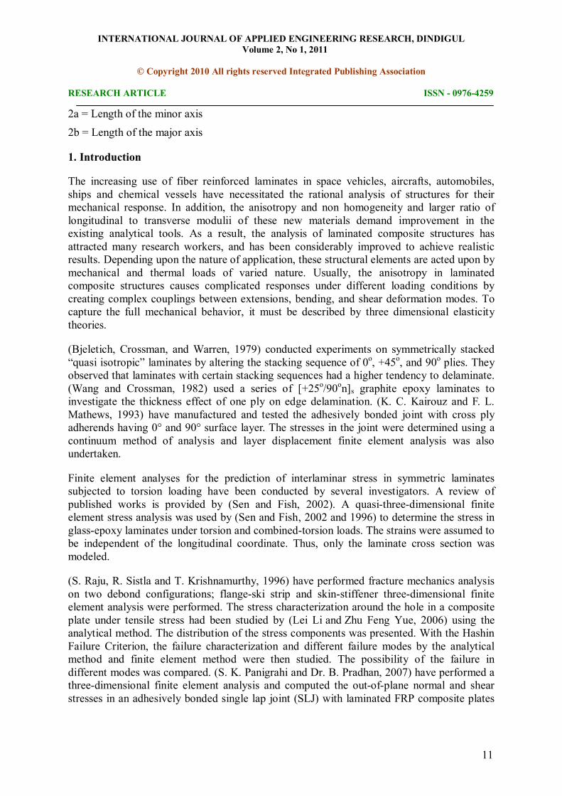
translations in the nodal x, y, and z directions. The element is suitable to model isotropic as well as orthotropic materials.
Figure 2: FE model on onefourth portion of laminate
3.3 Boundary Conditions and Loads
Clamped boundary conditions are applied along the side of the plate at y=A. Symmetric boundary conditions are applied on the surfaces at x=0 and y=0 of FE model. A uniform transverse pressure load of 1 MPa is applied on the top surface of the plate.
3.4 Material Properties
The following material properties are considered for the present analysis.
1. Young’s Modulii, E1= 147GPa, E2 = 10.3GPa, E3= 10.3GPa
2. Poisson’s Ratios, ν12= 0.27, ν23= 0.54, ν13 = 0.27 3. Rigidity Modulii, G12= G13= 7GPa, G23= 3.7GPa
4. Allowable tensile strengths in the three principal material directions: 5. Xt = 2280MPa, Yt = 57MPa, Zt = 57MPa
6. Allowable compressive strengths in the three principal material directions: 7. Xc = 1725MPa, Yc = 228MPa, Zc = 228MPa and
8. Shearing strengths of the orthotropic layer in various coupling modes: 9. Sxy = 76MPa, Syz = 76MPa, Sxz = 76MPa
10. Z = Interlaminar normal strength = 0.49 MPa

INTERNATIONAL JOURNAL OF APPLIED ENGINEERING RESEARCH, DINDIGUL Volume 2, No 1, 2011
© Copyright 2010 All rights reserved Integrated Publishing Association
RESEARCH ARTICLE ISSN 09764259
14
11. S = Interlaminar shear strength = 0.96 MPa
3.5 Validation of FE model
The present finite element model is validated by computing the out of plane stresses at the free surface i.e. at the bottom surface of the plate and away from the boundaries. At this location, all the outofplane stresses computed are found to be close to zero (Table1).
Table 1: Validation of the finite element model
Location σz (MPa) τyz (MPa) τzx (MPa)
(Bottom surface and away from boundaries) 0.093382 0.056243 0.092651
4. Results and Discussions
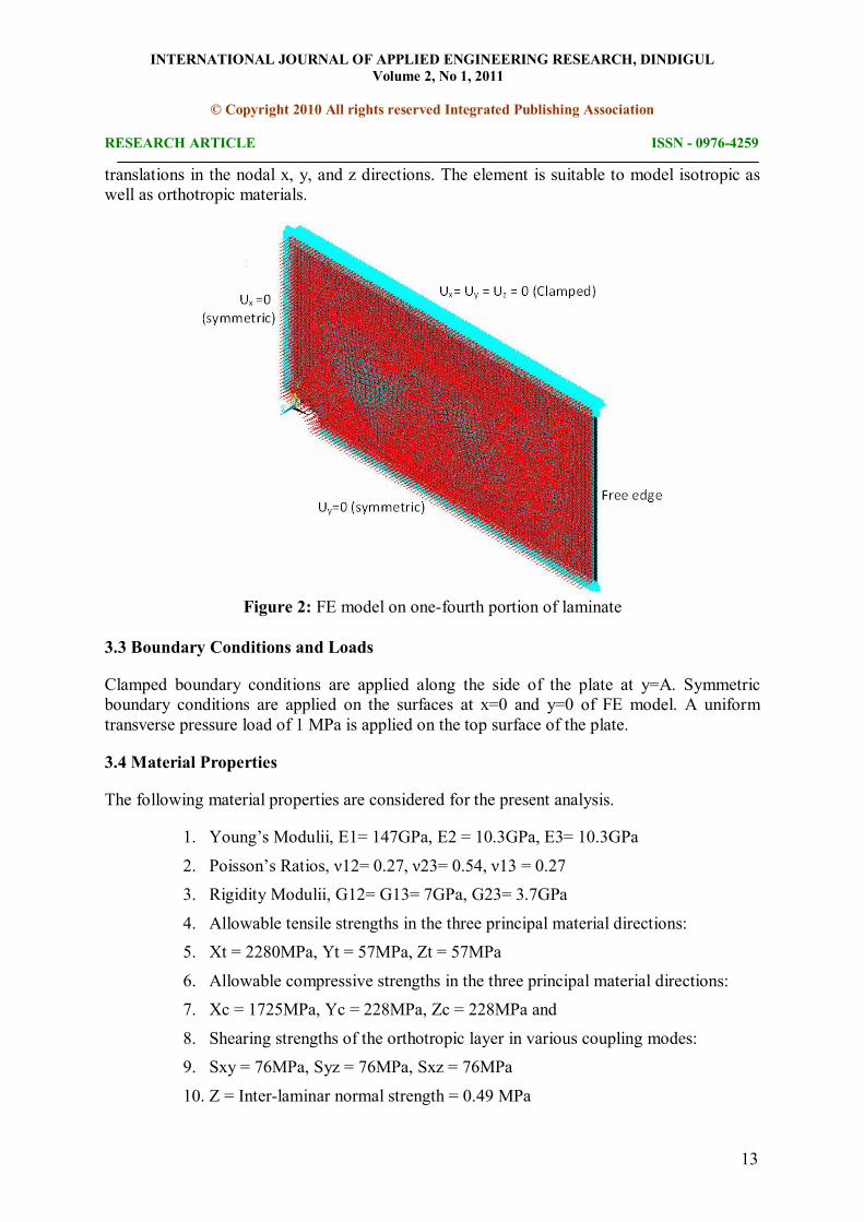
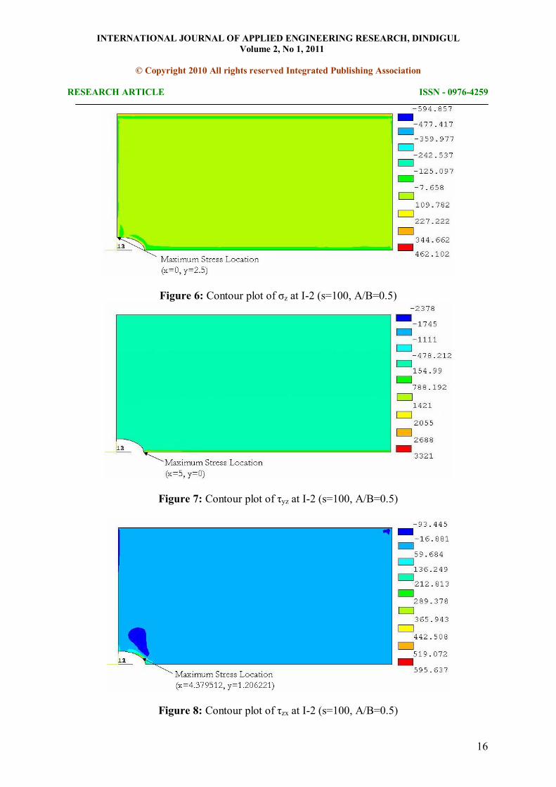
Outofplane stresses computed at the interfaces in case of a laminate (s=100, A/B=0.5) with an elliptical cut out are shown in Figs. 3 to 11. It is observed that the stress distribution is almost uniform except at the boundaries. At the first interface of the laminate the maximum σz and τyz are found at the mid span and on the hole boundary of the plate and the maximum value of τzx is at x=0 and y=2.5 as shown in Figs. 3 to 5 respectively. At the second interface of the laminate the maximum σz is at x=0 and y=2.5, the maximum τyz is found at the mid span and on the hole boundary of the plate and the maximum value of τzx is at x=4.379512 and y=1.206221 as shown in Figs. 6 to 8 respectively. At the third interface of the laminate the maximum σz and τyz are found at the mid span and on the hole boundary of the plate and the maximum value of τzx is at x=0 and y=2.5 as shown in Figs. 9 to 11 respectively.
After knowing the outofplane stresses from the stress analysis, which are responsible for the damages over the different interfaces, the next step is to use these data to compute the location of damage initiation. The failure is considered as a delamination damage which is mainly attributed to the interlaminar stress effects, so only the interlaminar shear stresses (τyz and τzx) and throughthethickness normal stress (σz) are required to predict the damage initiation. Under the three dimensional stress states, the failure can be evaluated by the Tsai Wu quadratic failure criterion equation given below (S.K.Panigrahi, B. Pradhan, 2007).
(σz/Z) 2 + (τyz/S) 2 + (τzx/S) 2 = e 2 if e < 1, no failure e ≥ 1, failure
From the above equation the failure index values are obtained at three interfaces. It is observed that at every interface of the laminate, the maximum failure index is greaterdhan the critical failure index and the failure occures at every interface of the laminate. The maximum failure index values at all the three interfaces of the laminate are located at the same point i.e. at x=5 and y=0.

INTERNATIONAL JOURNAL OF APPLIED ENGINEERING RESEARCH, DINDIGUL Volume 2, No 1, 2011
© Copyright 2010 All rights reserved Integrated Publishing Association
RESEARCH ARTICLE ISSN 09764259
15
Figure 3: Contour plot of σz at I1 (s=100, A/B=0.5)
Figure 4: Contour plot of τyz at I1 (s=100, A/B=0.5)
Figure 5: Contour plot of τzx at I1 (s=100, A/B=0.5)
INTERNATIONAL JOURNAL OF APPLIED ENGINEERING RESEARCH, DINDIGUL Volume 2, No 1, 2011
© Copyright 2010 All rights reserved Integrated Publishing Association
RESEARCH ARTICLE ISSN 09764259
16
Figure 6: Contour plot of σz at I2 (s=100, A/B=0.5)
Figure 7: Contour plot of τyz at I2 (s=100, A/B=0.5)
Figure 8: Contour plot of τzx at I2 (s=100, A/B=0.5)

INTERNATIONAL JOURNAL OF APPLIED ENGINEERING RESEARCH, DINDIGUL Volume 2, No 1, 2011
© Copyright 2010 All rights reserved Integrated Publishing Association
RESEARCH ARTICLE ISSN 09764259
17
Figure 9: Contour plot of σz at I3 (s=100, A/B=0.5)
Figure 10: Contour plot of τyz at I3 (s=100, A/B=0.5)
Figure 11: Contour plot of τzx at I3 (s=100, A/B=0.5)

INTERNATIONAL JOURNAL OF APPLIED ENGINEERING RESEARCH, DINDIGUL Volume 2, No 1, 2011
© Copyright 2010 All rights reserved Integrated Publishing Association
RESEARCH ARTICLE ISSN 09764259
18
To reduce this failure effect on the laminate, critical pressure load corresponding to e=1 is calculated by solving the problem at 10 equal load steps. For the estimation of pressure load, the graph (Fig. 12) is drawn between the load and the failure index (e) at A/B=0.5 and s=40 of the first interface of the laminate. It is observed that the failure index varies linearly with respect to load. From the linear relationship between the load and the failure index, the critical pressure load is found to be 0.1718 MPa. At critical conditions also the plate undergo failure. To reduce this failure effect, the pressure load of 0.1 MPa is applied to study the effect of other parameters on interlaminar failure of the laminate.
Figure 12: Variation of ‘e’ at I1 (A/B=0.5, s= 40)
Figures 13 to 15 show the variation of interlaminar failure index with respect to ‘s’ at three interfaces respectively. At the first interface, the laminate is safe up to (s=60, A/B=0.5), (s=40, A/B=0.75), and in remaining cases it undergoes failure as shown in Fig. 13. At the second interface, the laminate is safe up to (s=60 for A/B=0.75 and 1.0), (s=40, A/B=0.5), and in remaining cases it undergoes failure as shown in Fig. 14. At the third interface, the laminate is safe up to (s=80, A/B=0.75), (s=60, A/B=1.0) and in remaining cases it undergoes failure as shown in Fig. 15. From the overall observation of the graphs, the laminate is safe up to (s=40, A/B=0.5). These graphs reveal that, at the first interface of the laminate, the failure index is increasing with spantodepth ratio (s) and inplane aspect ratios (A/B), and is minimum at (s=40, A/B=0.5) and maximum at (s=100, A/B=1) as shown in Fig. 13. At the second interface of the laminate the failure index is increasing with ‘s’ and decreasing with (A/B), and is minimum at (s=40, A/B=1) and maximum at (s=100, A/B=0.5) as shown in Fig. 14. At the third interface of the laminate the failure index is increasing with ‘s’ and (A/B), and is minimum at (s=40, A/B=0.5) and maximum at (s=100, A/B=1) as shown in Figure 15.

INTERNATIONAL JOURNAL OF APPLIED ENGINEERING RESEARCH, DINDIGUL Volume 2, No 1, 2011
© Copyright 2010 All rights reserved Integrated Publishing Association
RESEARCH ARTICLE ISSN 09764259
19
Figure 13: Variation of ‘e’ with respect to ’s’ at I1
Figure 14: Variation of ‘e’ with respect to ’s’ at I2
Figure 15: Variation of ‘e’ with respect to ’s’ at I3
INTERNATIONAL JOURNAL OF APPLIED ENGINEERING RESEARCH, DINDIGUL Volume 2, No 1, 2011
© Copyright 2010 All rights reserved Integrated Publishing Association
RESEARCH ARTICLE ISSN 09764259
20
5. Conclusions
Interlaminar failure analysis of a four layered crossply laminate with elliptical cutout under cylindrical bending subjected to transverse pressure is performed using three dimensional FEM. The following conclusions are identified from the above failure analysis
1. The laminate is safe up to (s=40, A/B=0.5) 2. Failure index is maximum for s=100 and A/B=0.5.
3. It is identified that the failure index ‘e’ increasing with ‘s’ and (A/B) at first and third interfaces of the laminate, and is increasing with ‘s’ and decreasing with (A/B) at second interface of the laminate.
6. References
1. Bjeletich J. G. , Crossman F. W. and Warren W. J., (1979), The influence of stacking sequence on Failure Modes in QuasiIsotropic GraphiteEpoxy Laminates, Failure Modes in CompositesIV, J. R. Cornie and F. W. Crossman (editors), American Institute of Mining, Metallurgical and petroleum Engineers, New York ,118.
2. Crossman F. W. and Wang A. S. D., (1982), The Department of Transverse Cracking and Delamination on ply Thickness in GraphiteEpoxy Laminates, Damage in Composite Materials, ASTMSTP775, K. L. Reifsnider (editor) , 118.
3. Kairouz K. C. and Mathews F. L., (1993), Strength and Failure Modes of Bonded Single Lap Joints between Crossply Adherends, Composite Structures , 24(6); pp 475484
4. Sen J. K. and Fish J. c., Zhang C., Di S. and Zhang N., (2002), A new procedure for static analysis of thermoelectric laminated composite plates under cylindrical bending, Composite Structures, 56 , pp 13140.
5. Sen J. K. and Fish J. C., (1996), Failure prediction of composite laminates under Torsion, key engineering materials, Fracture of composites (Editor: E. Armanios Transtec publications) 121122; pp 285306.
6. Raju I. S., Sistla R. and Krishnamurty T., (1996), Fracture Mechanics Analysis for SkinStiffener Debonding, Engineering Fracture Mechanics (1996); 54(I); pp 371385.
7. Lei Li, Zhu Feng Yue, (2006), Analysis of Interlaminar Stresses and Failure around Hole Edge for Composite Laminates under InPlane Loading, Key Engineering Materials 324 – 325; pp 10271030.
8. S. K. Panigrahi and Dr. B. Pradhan, (2007), Three Dimensional Failure Analysis and Damage Propagation Behavior of Adhesively Bonded Single

INTERNATIONAL JOURNAL OF APPLIED ENGINEERING RESEARCH, DINDIGUL Volume 2, No 1, 2011
© Copyright 2010 All rights reserved Integrated Publishing Association
RESEARCH ARTICLE ISSN 09764259
21
Lap Joints in Laminated FRP Composites, Journal of Reinforced Plastics and Composites 26; pp 183201.