international journal of computational engineering research(ijcer)
TRANSCRIPT

International Journal of Computational Engineering Research||Vol, 03||Issue, 9||
||Issn 2250-3005 || ||September||2013|| Page 1
An Analytical Model Of The Rip Current Flow
Dr. Evans F. Osaisai Department of Mathematics, Niger Delta University, PMB 071, Yenagoa, Nigeria
P.O.Box 1693, Yenagoa, Bayelsa State Thu Sep 05 17:31:14 2013
I. INTRODUCTION The action of shoaling waves, and wave breaking in the surf zone, in generating a wave-generated
mean sea-level is well-known and has been extensively studied, see for instance the monographs of Mei (1983)
and Svendsen (2006). The simplest model is obtained by averaging the oscillatory wave field over the wave
phase to obtain a set of equations describing the evolution of the mean fields in the shoaling zone based on
small-amplitude wave theory and then combining these with averaged mass and momentum equations in the surf zone, where empirical formulae are used for the breaking waves. These lead to a prediction of steady set-
down in the shoaling zone, and a set-up in the surf zone. This agrees quite well with experiments and
observations, see Bowen et al (1968) for instance. However, these models assume that the sea bottom is rigid,
and ignore the possible effects of sand transport by the wave currents, and the wave-generated mean currents.
Hydrodynamic flow regimes where the mean currents essentially form one or more circulation cells are known
as rip currents. These form due to forcing by longshore variability in the incident wave field, or the effect of
longshore variability in the bottom topography (Kennedy 2003, 2005 ,Yu & Slinn 2003, Yu 2006 and others).
They are often associated with significant bottom sediment transport, and are dangerous features on many surf
beaches (Lascody 1998 & Kennedy 2005).
There is a vast literature on rip current due to wave-current interactions, see the recent works by (Horikawa 1978 , Damgaard et al. 2002, Ozkan-Haller & Kirby 2003 ,Yu & Slinn 2003 , Yu 2006, Falques,
Calvete & Monototo 1998a and Falques et al 1999b, Zhang et al 2004 and others) and the references therein.
Our purpose in this paper is to exploit the fully developed but under-utilised wave-current interaction theory in
the nearshore.In section 2 we record the usual wave-averaged mean field equations that are commonly used in
the literature. In section 3 we introduce a description of the rip current formation and examine the consequences
for both shoaling and surf zones. Then in section 4 we employ section 3 to a choice of linear depth profile. We
conclude with a discussion in section 5.
II. FORMULATION 2.1 Wave field
In this section we recall the wave-averaged mean flow and wave action equations that are commonly
used to describe the near-shore circulation (see Mei 1983 or Svendsen 2006 for instance). We suppose that the
ABSTRACT In this paper we develop an analytical theory for the interaction between waves and currents
induced by breaking waves on time-scales longer than the individual waves. We employed the wave-averaging procedure that is commonly used in the literature. The near-shore zone is often characterized
by the presence of breaking waves. Hence we develop equations to be used outside the surf zone, based
on small-amplitude wave theory, and another set of equations to be used inside the surf zone, based on
an empirical representation of breaking waves. Suitable matching conditions are applied at the
boundary between the offshore shoaling zone and the near-shore surf zone. Essentially we derive a
model for the interaction between waves and currents. Both sets of equation are obtained by averaging
the basic equations over the wave phase. Thus the analytical solution constructed is a free vortex
defined in both shoaling and surf zones. The surf zone solution is perturbed by a longshore component
of the current. Thus the presence of the rip current cell combined with the longshore modulation in the
wave forcing can drive longshore currents along the beach. The outcome, for our set of typical beach
profile, is a description of rip currents.
KEYWORDS: Wave-current interactions, surf zone, shoaling zone, matching conditions, wave-
averaging, rip currents, radiation stress.

An Analytical Model Of The Rip…
||Issn 2250-3005 || ||September||2013|| Page 2
depth and the mean flow are slowly-varying compared to the waves. Then we define a wave-phase averaging
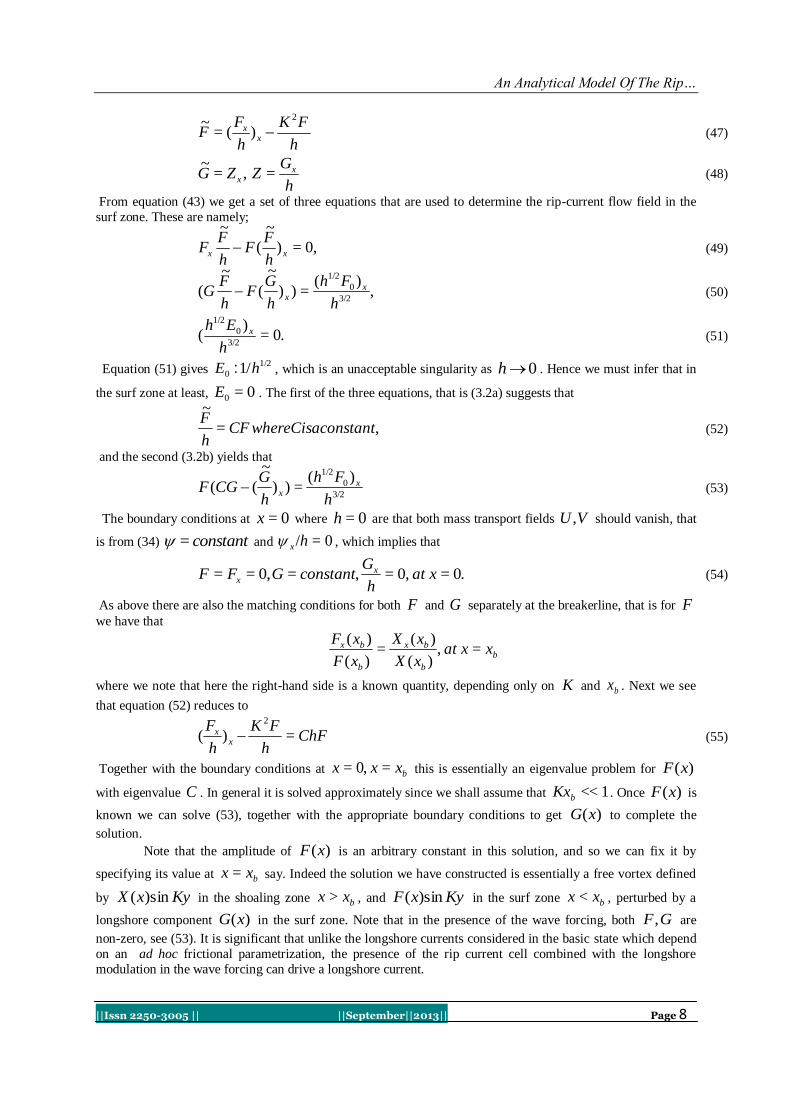
operator ff >=< , so that we can express all quantities as a mean field and a wave perturbation, denoted by a
“tilde” overbar. For instance,
.~
= (1)
where is the free surface elevation above the undisturbed depth )(= xhh . Then outside the surf zone, the
representation for slowly-varying, small-amplitude waves is, in standard notation,
.cos),(~
atx : (2)
Here ).(= txaa is the wave amplitude and ),(= tx is the phase, such that the wavenumber k , frequency
are given by
.==),(= tlkk (3)
The local dispersion relation is
HgUk tanh=,.= 2 (4)
.= 222 lkwhere
Here ),( txU is the slowly-varying depth-averaged mean current (see below), and ),()(=),( txxhtxH .
To leading order, the horizontal and vertical components of the wave velocity field are respectively
.sinsinh
)(sinh~,cossinh
)(cosh~
H
hzaw
H
hza
ku
:: (5)
Importantly, note that we have ignored here any reflected wave field, which is assumed to be very weak when
the bottom topography is slowly varying.
The basic equations governing the wave field is then the kinematic equation for conservation of waves
,0=tk (6)
which is obtained from (3) by cross-differentiation, the local dispersion relation (4), and the wave action
equation for the wave amplitude
.0=)( AcA gt (7)
Here /= EA , where /2= 2gaE is the wave energy per unit mass, and
)/=(,/== ddckcUc ggkg is the group velocity. Using the dispersion relation (4) in (6) we
get
,= exgt kck (8)
.= etgt c (9)
Here the subscript “e” denotes the explicit derivative of ),,( txk with respect to either x or t , when the
wavenumber k is held fixed. In this water case these explicit derivatives arise through the dependence of on
the mean height H and the mean current U .
2.2 Mean fields
The equations governing the mean fields are obtained by averaging the depth-integrated Euler
equations over the wave phase. Thus the averaged equation for conservation of mass is
.0=)(HUH t (10)
Here hH = where )(= xhh is the time-independent undisturbed depth. For the velocity field we
proceed in a slightly different way, that is we define
,= 'uUu (11)
where we define U so that the mean momentum density is given by
,><== dzuHUMh
(12)
But now we need to note that 'u does not necessarily have zero mean, and that U and u are not necessarily

An Analytical Model Of The Rip…
||Issn 2250-3005 || ||September||2013|| Page 3
the same. Indeed, from (11) and (12) we get that
.0>=<,><= dzuanduUu '
h
'
But )(= 2aOuu' , so that >< 'u is )( 2aO and it follows that, correct to second order in wave amplitude,
.>=),0,(>=<<=,=
k
c
EtxuuHMwhereMHuM '
ww (13)
The term wM in (13) is called the wave momentum.
Next, averaging the depth-integrated horizontal momentum equation yields (Mei 1983)
.>)=(<><.=).()( hhzpdzpIuuHUUHU ''
ht
Next an estimate of the bottom pressure term is made by averaging the vertical momentum equation to get
.><><.=)(>)=(< thh
dzwdzuwhghzp
For slowly-varying small-amplitude waves, the integral terms on the right-hand side may be neglected, and so
)(>)=(< hghzp . Using this in the averaged horizontal momentum equation, and replacing the
pressure p with the dynamic pressure )(= zpq yields
gHSHUUHU t .=).( (14)
.>~
2<>][=< 2 I
gdzqIuuSwhere
h
(15)
Here S is the radiation stress tensor. In the absence of any background current, so that U is )( 2aO , we may
use the linearized expressions (2, 5) to find that
.]2
1[ I
c
cE
EkcS
g
g
(16)
where the phase speed /=c , correct to second order in the wave amplitude.
2.3 Shoaling zone
These equations hold in the shoaling zone outside the surf zone (defined below). In summary, the
equations to be solved are that for the conservation of waves (6) combined with the dispersion relation (4), the
wave action equation (7), the averaged equation for conservation of mass (10) and the averaged equation for
conservation of horizontal momentum (14), where the radiation stress tensor is given by (16). In this shoaling
zone, we assume that wave amplitudes are small, and that there is no background current. Then all mean
quantities are )( 2aO , and in particular we can systematically replace H with h throughout these
equations.Next we shall suppose that )(= xhh depends only on the offshore co-ordinate 0>x , where the
undisturbed shoreline is at 0=x defined by 0=(0)h . Further, in the near-shore region, including all of the
surf zone, we shall assume that 0>xh . Then we seek steady solutions of the equation set in which all variables
are independent of the time t , and are also independent of the transverse variable y . It then follows from the
mean mass equation (10) that HU is constant, and since 0=H at the shoreline, it follows that we can set
0=U everywhere. Then in the dispersion relation (4) = . From the equation for conservation of waves
(6) we see that the frequency and the transverse wavenumber l are constants, and the the offshore
wavenumber k is then determined from the dispersion relation (4). As is well-known, it then follows that as
0H , || k , that is the waves refract towards the onshore direction, where we assume that the waves
are propagating towards the shoreline so that 0<k . The wave action equation (7) reduces to gEc is constant.
Near the shore, we can assume that the shallow water approximation holds and then 1/2)(ghcg , so that
,1/2
0
2
0
1/22 haha (17)

An Analytical Model Of The Rip…
||Issn 2250-3005 || ||September||2013|| Page 4
where 0a is the wave amplitude at a location offshore where 0= hh . The surf zone )(=<,< bbb xhhhxx
can then be defined by the criterion that bh is that depth where crAha =/ , defining an empirical breaking
condition. A suitable value is 0.44=crA , see Mei (1983) or Svendsen (2006).
The last step is to find the wave set-up from the mean momentum equation (14), which here
becomes
,,0=xx gHS (18)
.)2
1(cos= 2 E
c
cE
c
cSwhere
gg
Here is the angle between the wave direction and the onshore direction, and S is the “ xx ” component of
the tensor S . As 0h , /23,0, ESccg , and we recover the well-known result of a wave set-
down in the shoaling zone
.4
=4
=3/2
1/2
0
2
0
2
h
ha
h
a (19)
Here we have assumed that is zero far offshore. Note that the first expression for does not need the use
of the shallow water approximation, as shown by Longuet-Higgins and Stewart (1962).
2.4 Surf zone
In the surf zone bb hhxx <<,0<<0 , we make the usual assumption (see Mei (1983) for instance)
that the breaking wave height a2 is proportional to the total depth H , so that
,8
=,=222Hg
EorHa
(20)
Here the constant is determined empirically, and a typical value is 0.88.= . To determine the mean
height hH = , we again use the mean momentum equation (14), but now assume that
/2=/23= 2gHES where /83= 2 , so that
,)(1
=,0=)(
b
bxx
hhHHthatsohHHHH (21)
where the constant bbb hH = is determined by requiring continuity of the total mean height at bxx = .
Note that using (19)
,/4= 3/21/2
0
2
0 bbb hhahH
and since bH must be positive, there is a restriction on either the deep-water wave amplitude 0a or on the
breaker depth bh ,
./</4 5/2
0
5/22
0
2
0 hhha b (22)
Note that the expression (21) is valid for any depth )(xh , although in the literature it is often derived only for a
linear depth profile xh = .
We are now in a position to determine the displaced shoreline sxx = , defined by the condition that
0=H . That is, if )(= ss xhh then )/1(= shhH , where
,)(1= bbs hh (23)
Note that to use the expression (23) it may be necessary to extend the definition )(xh into 0<x . For instance
for a linear beach, xh = , this is straightforward, but for a quadratic beach profile, 2= xh , the extension
for negative x should be 2= xh say. Note that from (19),

An Analytical Model Of The Rip…
||Issn 2250-3005 || ||September||2013|| Page 5
,4
=3/2
1/2
0
2
0
b
bh
ha
and, on combining this with the condition (22), it follows that the shoreline recedes (advances), that is
0)0(><sh when
./<4
<1
,1
<4
5/2
0
5/2
2
0
2
0
5/2
0
5/2
5/2
0
5/2
2
0
2
0
hhh
a
h
hor
h
h
h
a
bb
b
(24)
Curiously, this anomalous result does not seem to have been noticed previously [5] and [5]. Since there is an
expectation that the shoreline should advance (see Dean and Dalrymple (2002) for instance), essentially it states that the present model is only valid for sufficiently small waves far offshore, defined by the first inequality in
(24), which slightly refines the constraint (22).
III. A GENERAL DESCRIPTION OF THE RIP CURRENT FORMATION Here we consider a steady-state model driven by an incident wave field which has an imposed
longshore variability. The wave field satisfies equation (7) which in the present steady-state case reduces to
.0=)sin()cos( gg EcyEcx (25)
Here we again assume that )(= xhh and that consequently the frequency and the longshore wavenumber
l are constants, while the onshore wavenumber K is then determined from equation (4). We have the wave
energy E of the form
,)(sin)(cos)(= 000 xGKyxFKyxEE (26)
where the longshore period K/2 is imposed. These equations in the shoaling zone yields
0=sin)cos( 00 gxg cKFcE (27)
0=sin)cos( 00 gxg cKEcF (28)
0.=)cos( 0 xgcG (29)
on collecting terms in Kycos , Kysin and the constant term, which form three equations for 0E , 0F and
0G . Equation (29) easily yields that .=cos0 constantcG g In shallow water, we may approximate by
putting 1/2ghcg and 1cos , so that then
1/2
0 /hconstantG . For the remaining equations we can use
Snell’s law, bbb cc =/sin=/sin (the constant value, here evaluated at the breaker line), and the shallow-
water approximation to get that
,0=})/){( 2
0
22
0 cEKccE bxx (30)
while although 0F satisfies the same equation, once 0E has been found, then 0F is given by either (27) or
(28). In practice, 1<<Kc and so approximately we can assume that constantcFE ),( 00 , the usual
shallow-water expressions. Note that here ghc . In the surf zone, the expressions )(),(),( 000 xGxFxE is
determined empirically. Once the expression (26) has been determined, we may then substitute into the expressions (27,28 &
29) to obtain the radiation stress fields. Our aim here then is to describe how steady-state rip currents are forced
by this longshore modulation of the incident wave field, especially in the surf zone.
The forced two-dimensional shallow water equations that we use here are characteristic of many
nearshore studies (Horikawa 1978 , Damgaard et al. 2002, Ozkan-Haller & Kirby 2003 ,Yu & Slinn 2003 , Yu
2006, Falques, Calvete & Monototo 1998a and Falques et al 1999b, Zhang et al 2004 and others). Then,
omitting the overbars as before, then equations (??) in the present steady-state case reduce to
],[=][ xxHgyUVxUUH (31)

An Analytical Model Of The Rip…
||Issn 2250-3005 || ||September||2013|| Page 6
],[=][ yyHgyVVxVUH (32)
where the stress terms are defined;
.== 22211211 ySxSandySxS yx (33)
Next we observe that equation (10) can be solved using a transport stream function ),( yx , that is
,1
=1
= xH
andyH
U (34)
Next, eliminating the pressure, we get the mean vorticity equation
x
y
yx
xyyxHHHH
][][=)()(
(35)
where is define as
.)()(== y
y
xx
yxHH
UV
(36)
We shall solve this equation (35) in the shoaling zone bxx > and in the surf zone bxx < , where as before
bxx = is the fixed breaker line. It will turn out that the wave forcing occurs only in the surf zone, but
continuity implies that the currents generated in the surf zone must be continued into the shoaling zone.
3.1 Shoaling zone
In bxx > we shall assume that hH as is )( 2aO . Then we shall use the expressions [27 ,28]
to evaluate the radiation stress tensor. For simplicity, we shall also use the shallow-water approximation that
ghccg , and so we get that
)2
1sin(=,cossin==,)
2
1cos(= 2
2221122
11 ESESSES (37)
These expressions are in principal known at this stage, and so we can proceed to evaluate the forcing term on
the right-hand side of (35). To assist with this we recall Snell’s law
bbhh sin=sin
where bh and b are the water depth and incidence angle at the breaker-line. Now the energy equation (25) has
the approximate form
,0=)sin()cos( yx cEcE
and using Snell’s law, this can be written as
0,=)cossin()cos( 2
c
cEEE x
yx
.2
1=
c
cEEsoand x
xx
We can also deduce from (25) that
,0=)sin()cossin( 2yx EE
.2
1= yy Esoand
We can now evaluate the right-hand side of (35), and find that its identically zero,
0.=][][ x
y
yx
hh
Thus in the shoaling zone there is no wave forcing in the mean vorticity equation, although of course there will
be a mean pressure gradient. However, this does not concern us since here our aim is to find only the flow field.
Note that the result that there is no wave forcing in the vorticity equation does not need the specific form (26),

An Analytical Model Of The Rip…
||Issn 2250-3005 || ||September||2013|| Page 7
and is based solely on the steady-state wave energy equation (25). The specific form (26) is only used in the surf
zone.
With no forcing term, the vorticity equation (35) can be solved in the compact form, noting that we again
approximate H with h ,
.)(= Fh
(38)
But here 0=)(F from the boundary conditions in the deep water as x , where the flow field is zero.
Thus our rip current model has zero vorticity in the shoaling zone. It follows that we must solve the equation
0,=)1
()1
(= yyxxhh (39)
in bxx > . Since )(= xhh we can seek solutions in the separated form
)()(= yYxX (40)
with the outcome that
0.=,0=)( 22
YKYh
XK
h
Xyyx
x (41)
We note the separation constant LK /2=2 must not be zero, and is in fact chosen to be consistent with the
modulation wavenumber of the wave forcing. Without loss of generality, we can choose
.sin= KyY (42)
For each specific choice of )(xh we must then solve for )(xX in bxx > , with the boundary condition that
0X as x . We shall give details in the following subsections. Otherwise we complete the solution by
solving the system (35) in the surf zone, and matching the solutions at the breakerline, bxx = where the
streamfunction must be continuous, and in order to have a continuous velocity field we must also have that
x is continuous.
3.2 Surf zone
To make sense of wave forcing, we assume that the expression (26) holds in this region. The functions
)(),(),( 000 xGxFxE are then determined empirically. To determine the wave forcing term in the mean
vorticity equation (35) we shall assume that 1<<= b so that, on using (??) and (37) we get that
.2
1=,
2
3= yyxx EE
Then (35) now becomes, where we again approximate H with )(xh ,
,)(
=2
=~~
3/2
1/2
2 h
Eh
h
hE
h
Exyyx
xyxyxy (43)
where here h/=~
is the potential vorticity. Since the wave forcing is given by (26), that is
,)(sin)(cos)(= 000 xGKyxFKyxEE (44)
we observe that the unmodulated term )(0 xG plays no role here at all, although of course it will contribute to
the wave setup. In order to match at bxx = with the expression (42) for the streamfunction in the shoaling
zone, we should try for a solution of (43) of the form
.<,)(sin)(= bxxinxGKyxF (45)
The matching conditions for the streamfunction and velocity field at the breakerline bxx = require that
.0=)(,0=)=(,)(=)(,)(=)( bxbbxbxbb xGxxGxXxFxXxF
The expression (45) yields
GKyF~
sin~
= (46)
where F~
and G~
are differential operators where they are defined as;
An Analytical Model Of The Rip…
||Issn 2250-3005 || ||September||2013|| Page 8
h
FK
h
FF x
x
2
)(=~
(47)
h
GZZG x
x =,=~
(48)
From equation (43) we get a set of three equations that are used to determine the rip-current flow field in the
surf zone. These are namely;
,0=)
~
(
~
xxh
FF
h
FF (49)
,)(
=))
~
(
~
(3/2
0
1/2
h
Fh
h
GF
h
FG x
x (50)
.0=)
(3/2
0
1/2
h
Eh x (51)
Equation (51) gives 1/2
0 1/hE : , which is an unacceptable singularity as 0h . Hence we must infer that in
the surf zone at least, 0=0E . The first of the three equations, that is (3.2a) suggests that
,=
~
onstantwhereCisacCFh
F (52)
and the second (3.2b) yields that
3/2
0
1/2 )(=))
~
((h
Fh
h
GCGF x
x (53)
The boundary conditions at 0=x where 0=h are that both mass transport fields VU , should vanish, that
is from (34) constant= and 0=/hx , which implies that
.0=,0=,=,0== xath
GconstantGFF x
x (54)
As above there are also the matching conditions for both F and G separately at the breakerline, that is for F
we have that
b
b
bx
b
bx xxatxX
xX
xF
xF=,
)(
)(=
)(
)(
where we note that here the right-hand side is a known quantity, depending only on K and bx . Next we see
that equation (52) reduces to
ChFh
FK
h
Fx
x =)(2
(55)
Together with the boundary conditions at bxxx =0,= this is essentially an eigenvalue problem for )(xF
with eigenvalue C . In general it is solved approximately since we shall assume that 1<<bKx . Once )(xF is
known we can solve (53), together with the appropriate boundary conditions to get )(xG to complete the
solution.
Note that the amplitude of )(xF is an arbitrary constant in this solution, and so we can fix it by
specifying its value at bxx = say. Indeed the solution we have constructed is essentially a free vortex defined
by KyxX sin)( in the shoaling zone bxx > , and KyxF sin)( in the surf zone bxx < , perturbed by a
longshore component )(xG in the surf zone. Note that in the presence of the wave forcing, both GF, are
non-zero, see (53). It is significant that unlike the longshore currents considered in the basic state which depend
on an ad hoc frictional parametrization, the presence of the rip current cell combined with the longshore
modulation in the wave forcing can drive a longshore current.

An Analytical Model Of The Rip…
||Issn 2250-3005 || ||September||2013|| Page 9
IV. AN APPLICATION TO LINEAR DEPTH PROFILE To make sense of the rigorous mathematical derivations and formulations we then suppose that
xh = . Then immediately the solutions of equation (41) in the shoaling zone is
).()(=)( 1011 KxxICKxxKCxX
Since 1I becomes unbounded at =x , the boundary condition 0X as x gives 0=0C , and so
we get that
.>,)(=)( 11 bxxKxxKCxX (56)
The behavior of the Bessel functions depict the rip-current character which decays exponentially away
from the breakerline, on the scale 1K . It is interesting to note here that the bottom slope does not appear in
this solution at all. In the surf zone, the boundary condition (54) implies that as 0x , 2
0)( xAxF . We
shall make the approximation that the shoaling zone has a small cross-shore width, in which case it is easily
seen that the right-hand side of (55) is much smaller that the left-hand side, and is )( 3xO . Approximating the
right-hand side accordingly we get that
,=1 4
0
2 xAFKFx
F xxx (57)
where 2= C . This is useful, as the solutions of the homogeneous equation on the left-hand side are known,
namely )(= 1 KxxIja and )(= 1 KxxKjb . By the variation of parameters one gets
,)()(=)( 21 baba jCjCjxBjxAxF (58)
noting that xjjW ba =),( , where
.=)(,=)( 3
00
3
00
dxxAjxBdxxAjxA a
x
b
x
(59)
The boundary condition at 0=x shows that 0,=2C and the normalization of F as 0x implies that
.2= 01 AkC It remains to apply the boundary condition at bxx = which then yields (that is C ). From
equations (58), (59) one gets
).24
(14
2
0
xxAF
Note that to this order, F is independent of K where scales as 4
bx so this small bx approximation also
requires that the constant also be very small. Similarly the right-hand side may be approximated by
/2))(ln( 0
22
bb KxxK
where 0 is Euler’s constant. This implies that to leading order
8.4 bx (60)
But this is a bit too simple as can be seen from the consequent expression for
),3
(14
42
0
bx
xxAF (61)
so that actually 0xF at bxx = , which is too simple. The higher-order terms in A and B can be found,
and then we get that
]).72
1
12824[
192
1
8
1(= 82
86642
0 xKxx
xxxAF
We define 1<<=18
1 4 bx and keeping the required next order terms we get that
,]12
1))(ln[(
3
2= 0
22 bb KxxK

An Analytical Model Of The Rip…
||Issn 2250-3005 || ||September||2013|| Page 10
]).12
1)(ln][
9
2[
91638
1(1= 02
42
4
62
4
6
4
422
0 b
bbbb
Kxx
xK
x
xK
x
x
x
xxxAF
Figure 1: Plot of 0)/( AxF against bxx/ , where 0A is arbitrary as given by equation (61).The figure shows
that there is only curve at leading order. We note that there is no dependence on the slope and only a weak
dependence on K .We observe that )(xF reaches a maximum value of 0.7.)/( 0 AxF Beyond this point
)(xF may probably decrease monotonically.
Next for the y -independent component, we need to solve for )(xG from(53). As above, we
approximate 2
0= xAF , and we use the empirical expression /8= 22
0 hF . This yields
xA
gCGxZ
xZ xxx
0
2222
16
5=
1 (62)
There is a singularity at 0=x , which can be analyzed by setting 2= xu so that (62) becomes
,16
5=4
3/2
0
23
uA
gZZuu
(63)
where we have put 0>= and the full solution is
])2
[sin2sin
1(
12
5=
2
2
0
22
bb
b
x
x
x
x
A
xgZ
(64)
Finally the complete the stream function )(xG is found by integrating hZGx = subject to the boundary
condition that 0=G at bxx = . Thus we get that, for bxx <<0 ,
.)2tan22
1
3
1]
2[cos
2sin22
1
3(
12
5=)(
2
2
3
3
0
323
bb
b
x
x
x
x
A
xgxG
(65)
Note in particular that 0(0)G and is the net mean longshore mass transport in the rip current system.
Figure 2: Depicts the plots of normalized )(xZ and )(xG given by equations 64 and 65 where each is
normalized by 0
22 /125 Axg b and 0
23 /125 Ag respectively with 0A arbitrary. Observe that in the
figure [2] there is a small region of reversed flow near the breaker line.
The combined expressions (56, 61, 65) complete the solution, where we recall that the constant C is
given by (60) (since 2= C ), or their respective higher-order corrections. Note that the amplitude of )(xF
at bxx = is given by
.)(=)( 11 bbb KxKxCxF
On using the approximation 1<<bKx , and the approximate expression (61), this reduces to
.=3
2=)( 1
2
0
K
CxAxF b
b
The rip-current system contains a free parameter 0A or its equivalent. We choose to define this free parameter
to be the value of )( bxF and normalize the full solution by this value. Thus we get from (40, 42) in bxx > ,
and (45, 61, 65) in bxx < that the normalized streamfunction n is given by
,>,)(sin)(
)(= b
b
n xxforKyxX
xX (66)

An Analytical Model Of The Rip…
||Issn 2250-3005 || ||September||2013|| Page 11
.<<0,(0)
)(sin
)(
)(= b
b
n xxforG
xGRKy
xF
xF (67)
Here )((0)/= bxFGR is a free parameter. Thus a larger (smaller) R decreases the circulation of the rip-
current system vis-a-vis that of the longshore current component. From (61, 65) we find that here
.)2tan22
1
3
1(
8
5=
2
0
23
A
xgR b
(68)
Note that with all other parameters fixed, a larger (smaller) slope increases (decreases) R . In order to
estimate typical values for R we note that from (61) the longshore velocity field in the “ )(sin Ky ”-component
scales as /= 0AVc , while the longshore component then scales with cRV . Taking account of the actual
numerical values in the expressions given above, we find that a suitable values are 0.1R . Plots of n are
shown in figures 3, ??, 4 for 20.5,0.2,0.1,0.02,= R respectively, with 0.2=bKx (noting that our
present theory requires that bKx is small).
Figure 3: Plot of the rip current streamlines for a linear depth profile, given by equation (67) where )(xF and
)(xG are equations (61) and (65) respectively for 0.02= R in the left panel and 0.1= R in the right
panel
Figure 4: As for figure 3 but 0.5= R in the left panel and 0.2= R in the right panel
From the plots in figures 3, ?? we see that as || R increases, the core of the rip current circulation
moves from the shoaling zone towards the surf zone. The reason for this is that the solution we have constructed
is essentially a free vortex defined by KyxX sin)( in the shoaling zone bxx > , and KyxF sin)( in the surf
zone bxx < , perturbed by a longshore component )(xG in the surf zone. Since 0<R , this longshore
component opposes the vortex flow in the cell <<0 Ky but is in sympathy for 2<< Ky . This has
the effect of moving the vortex cell further offshore in the sector 2<< Ky relative to the sector
<<0 Ky . Note that || R increases as the wave forcing increases, or as the slope increases, or as the
depth bx at the breaker line increases.
V. CONCLUSION We described qualitative solutions for rip currents which are essentially free vortices in both zones.
The free vortex in the surf zone is perturbed by a longshore modulation in the wave forcing. Rip current cell
combining with the longshore modulation in the wave forcing can drive longshore currents along the beach.
Thus the dynamics of the shoaling zone is only dependent on the state-state wave energy equation.The wave
forcing in the surf zone sets the wave activities different from those of the shoaling zone. To determine wave forcing in the mean vorticity equation we assume that the wave angle becomes smaller. We also note here that
the component of the radiation stress in the y momentum remains unchanged across the entire flow domain.
This shows that it is only the x component of the radiation stress that play a leading role in the wave forcing.
However, wave forcing encountered in the surf zone has an unmodulated term that does not play a role in the
vorticity equation but only contribute to wave setup.To ensure continuity of the streamfunctions in the shoaling
zone we match the solution at the breakerline by a matching condition with appropriate boundary conditions.
Thus the rip currents solution in the surf zone is provided by the terms in the matching condition. The terms in
the matching condition has a cross-shore width and a modulated longshore component. The cross-shore width
was determined by the application of perturbation method and variation of parameter. It would to interesting to
examine the effect of friction on the rip currents.
REFERENCES [1] Baldock, T.E, ( 2006), Long wave generation by the shoaling and breaking of transient wave groups on a beach, Proceedings of
the Royal society, vol.462, pp 1853-1876.

An Analytical Model Of The Rip…
||Issn 2250-3005 || ||September||2013|| Page 12
[2] Baldock, T.E., O’Hare, T.J. & Huntley, D.A, (2004), Long wave forcing on a barred beach, Journal of Fluid Mechanics, vol
503, pp. 321-343.
[3] Battjies, J. A., (1988), Surf zone dynamics, Annual Rev. Fluid Mechanics, vol. 20, pp.257-293.
[4] Billigham, J & King, A.C., (2000), Wave Motion- Cambridge Texts in Applied Mathematics, Cambridge University Press.
[5] Brocchini, M., Kennedy, A., Soldini, L & Mancinelli, A., (2004) Topographically controlled, breaking-wave-induced
macrovortices. Part 1. Widely separated breakwaters, J. Fluid Mechanics, vol. 507, pp. 289-307.
[6] Buhler, O., (2000), On the vorticity transport due to dissipating or breaking waves in shallow-water flow, Journal of Fluid
Mechanics, vol 407, pp 235-263.
[7] Buhler, O. & Jacobson, T. E., (2001), Wave-driven currents and vortex dynamics on barred beaches, Journal of Fluid Mechanics,
vol 449, pp 313-339.
[8] Damgaard, J., Dodd, N., Hall, L. & Chesher, T., (2002), Morphodynamic modelling of rip channel growth, Coastal Engineering,
vol.45, pp 199-221.
[9] Davies, A. M. & Lawrence, J. (1995), Modelling the effect of wave-current interaction on the three-dimensional wind driven
circulation of the Eastern Irish Sea, Journal of Physical Oceanography, vol. 25, pp. 29-45.
[10] Falques, A., Calvete, D.& Monototo, A. (1998a), Bed-flow instabilities of coastal currents. In Physics of Estuaries and Coastal
Seas, pp. 417- 424. A. A. Balkema.
[11] Falques, A., Montoto, A. & Vila, D. (1999), A note on hydrodynamic instabilities and horizontal circulations in the surf zone,
Journal of Geophysical Research, vol. 104(C9), pp 20605-20615
[12] Falques, A., Coco, G & Huntley, D.A (2000), A mechanism for the generation of wave-driven rhythmic patterns in the surf zone,
Journal of Geophysical Research, vol. 105, No. C10, pp 24701-20615.
[13] Guza, R. T. & Davis, R. E. (1974), Excitation of edge waves by waves incident on a beach, Journal of Geophysical Research,
vol. 79, C9, pp. 1285-1291.
[14] Horikawa, K (1978), An Introduction to Ocean Engineering, University of Tokyo Press.
[15] Kennedy, A.B. (2003), A circulation description of a rip current neck, Journal of Fluid Mechanics, vol. 497, pp. 225-234
[16] Kennedy, A.B. (2005), Fluctuating circulation forced by unsteady multidirectional breaking waves, Journal of Fluid Mechanics,
vol. 538, pp. 189-198
[17] Kennedy, A.B., Brocchini, M., Soldini, L., & Gutierrez. E., (2006), Topographically controlled, breaking-wave-induced
macrovortices. Part 2. Changing geometries, J. Fluid Mechanics, vol. 559, pp. 57-80.
[18] Lane, E.M & Restrepo, J.M (2007), Shoreface-connected ridges under the action of waves and currents, Journal of Fluid
Mechanics, vol. 582, pp. 23-52
[19] Lascody, L. L (1998), East central Florida rip current program, National Weather Digest, vol. 22, pp. 25-30.
[20] List, J.H. (1992), A model for the generation of two dimensional surf beat, Journal of Geophysical Research, vol. 97, pp. 5623-
5635.
[21] Longuet-Higgins, M.S. (1970), Longshore currents generated by obliquely incident sea waves, 1, J. Geophysical Research, vol.
75, pp 6778-6789.
[22] Longuet-Higgins, M.S. (1970), Longshore currents generated by obliquely incident sea waves, 2, J. Geophysical Research, vol.
75, pp 6790-6801.
[23] Longuet-Higgins, M.S & Stewart, R.W. (1960), The changes in the form of short gravity waves on long waves and tidal currents,
Journal of Fluid Mechanics, vol. 8, pp 565-583
[24] Longuet-Higgins, M.S & Stewart, R.W. (1961), The changes in amplitude of short gravity waves on on steady non-uniform
currents, Journal of Fluid Mechanics, vol. 10, pp 529-5549
[25] Longuet-Higgins, M.S & Stewart, R.W. (1962), Radiation stress and mass transport in gravity waves, with application ro surf
beats, Journal of Fluid Mechanics, vol. 13, pp 481-504
[26] Longuet-Higgins, M.S & Stewart, R.W. (1964), Radiation stress in water waves: a physical discussion with applications, Deep-
sea Research, vol. 11, pp. 529-562.
[27] Longuet-Higgins, M.S. (2005), On wave set-up in shoaling water with a rough sea bed, Journal of Fluid Mechanics, vol. 527, pp.
217-234
[28] Mei, C.C. (1983), Applied Dynamics of Ocean Surface Waves, John Wiley and Sons, Inc.
[29] Osaisai, E. F (2008), The interaction between waves and currents in the nearshore zone, PhD thesis, Loughborough University.
[30] Peregrine, D.H. (1998), Surf zone currents, Theoretical and Computational Fluid Dynamics, vol. 10, pp 295-309.
[31] Rahman, M. (2002), Mathematical methods with applications, WITPress, Southampton.
[32] Restrepo, J. M. (2001), Wave-current interactions in shallow waters and shore-connected ridges, Continental Shelf Research, vol.
21, pp. 1331-1360.
[33] Roger Grimshaw and Evans Osaisai (2012), Modeling the effect of bottom sediment transport on beach profiles and wave set-up,
ocean Modelling, 59-60 (2012) 24-30
[34] Shepard, F. P., Emery, K. O. & La Fond, E. C (1941), Rip currents: a process of geological importance, Translation of American
Geophysical Union, vol. 31, pp. 555-565.
[35] Tucker, M.J., (1950), Surf beats: sea waves of 1 to 5 min. period, Proc. R. Soc. London, vol. 202, pp. 565-573.
[36] Yu, J. & Mei, C.C. (2000), Formation of sand bars under surface waves, Journal of Fluid Mechanics, vol. 416, pp. 315 - 348.
[37] Yu, J. & Mei, C.C. (2000), Do longshore bars shelter the shore?, Journal of Fluid Mechanics, vol. 404, pp. 251 - 268.
[38] Yu, J. & Slinn, D.N. (2003), Effects of wave-current interaction on rip currents, Journal of Geophysical Research, vol 108 (C3),
3088.
[39] Yu, J. (2006), On the instability leading to rip currents due to wave-current interaction, Journal of Fluid Mechanics, vol. 549, pp.
403-428.