international journal of core engineering & management...
TRANSCRIPT

International Journal of Core Engineering & Management (ISSN: 2348-9510) Special Issue, NCETME -2017, St. Johns College of Engineering and Technology, Yemmiganur
102
SHAPE OPTIMIZATION OF A HEAVY VEHICLE CHASSIS FOR MAXIMUM LOAD CONDITIONS
U.SURESH 1
ASST PROFESSOR, DEPARTMENT OF MECHANICAL ENGINEERING, VNR VIGNAN JYOTHI COLLEGE OF ENGINEERING, AFFILIATED TO J.N.T.UNIVERSITY
HYDERABAD. HYDERABAD.INDIA. [email protected]
M.KHAJA GULAM HUSSAIN 2
ASST PROFESSOR, DEPARTMENT OF MECHANICAL ENGINEERING, RAJIV GANDHI MEMORIAL COLLEGE OF ENGINEERING & TECHNOLOGY, AFFILIATED
TO J.N.T.UNIVERSITY ANANTAPUR. NANDYAL, A.P.INDIA. [email protected]
S.RAJENDRA 3
ASST PROFESSOR, DEPARTMENT OF MECHANICAL ENGINEERING, VNR VIGNAN JYOTHI COLLEGE OF ENGINEERING, AFFILIATED TO J.N.T.UNIVERSITY
HYDERABAD. HYDERABAD.INDIA.
Abstract
I. Composite material is a material composed of two or more distinct phases (matrix phase and dispersed phase) and having bulk properties significantly different from those of any of the constituents. Different types of composite material are available and one of it is Polymer matrix composite. It is very popular due to their low cost and simple fabrication methods. It has the benefits of high tensile strength, high stiffness and good corrosion resistance etc. At present these polymer matrix composite materials are used in aerospace, automobile industries due to it high strength to low weight ratio.
II. For vehicles chassis consists of an assembly of all the essential parts of a truck (without the body) to be ready for operation on the road.
III. In my thesis, design and model the heavy vehicle chassis by using Pro-E software, by taking the data from the L & T heavy vehicle model by reverse engineering processes. The shear strength of chassis is determined theoretically and compared with FEA analysis. The shape of the heavy vehicle chassis is optimized by taking C – Channel and Box type. And also optimization is done to reduce the weight of
International Journal of Core Engineering & Management (ISSN: 2348-9510) Special Issue, NCETME -2017, St. Johns College of Engineering and Technology, Yemmiganur
103
frame on the chassis. Present used material for chassis is steel. Replacing the chassis material with Kevlar fiber and S+R Glass. And we are using layer stacking method for the manufacturing of polymer matrix composite by varying layer sizes and using of damping material in it. By using steel, the weight of the chassis is more compared with Kevlar fiber and S+R Glass Epoxy, since its density is more. FEA analysis is done on chassis for optimizing above parameters under 10 tons load. Index Terms— Software used for modeling Pro/Engineer and for analysis ANSYS
I. INTRODUCTION
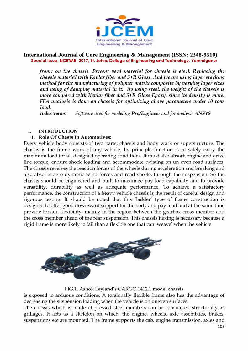
1. Role Of Chasis In Automotives: Every vehicle body consists of two parts; chassis and body work or superstructure. The chassis is the frame work of any vehicle. Its principle function is to safely carry the maximum load for all designed operating conditions. It must also absorb engine and drive line torque, endure shock loading and accommodate twisting on un even road surfaces. The chassis receives the reaction forces of the wheels during acceleration and breaking and also absorbs aero dynamic wind forces and road shocks through the suspension. So the chassis should be engineered and built to maximize pay load capability and to provide versatility, durability as well as adequate performance. To achieve a satisfactory performance, the construction of a heavy vehicle chassis is the result of careful design and rigorous testing. It should be noted that this ‘ladder’ type of frame construction is designed to offer good downward support for the body and pay load and at the same time provide torsion flexibility, mainly in the region between the gearbox cross member and the cross member ahead of the rear suspension. This chassis flexing is necessary because a rigid frame is more likely to fail than a flexible one that can ‘weave’ when the vehicle
FIG.1. Ashok Leyland’s CARGO 1412.1 model chassis is exposed to arduous conditions. A torsionally flexible frame also has the advantage of decreasing the suspension loading when the vehicle is on uneven surfaces. The chassis which is made of pressed steel members can be considered structurally as grillages. It acts as a skeleton on which, the engine, wheels, axle assemblies, brakes, suspensions etc are mounted. The frame supports the cab, engine transmission, axles and
International Journal of Core Engineering & Management (ISSN: 2348-9510) Special Issue, NCETME -2017, St. Johns College of Engineering and Technology, Yemmiganur
104
various other components. Cross members are also used for vehicle component mounting and protecting the wires and tubing that are routed from one side of the vehicle to the other. The cross members control axial rotation and longitudinal motion of the main frame, and reduce torsion stress transmitted from one rail to the other. TYPES OF FRAMES:
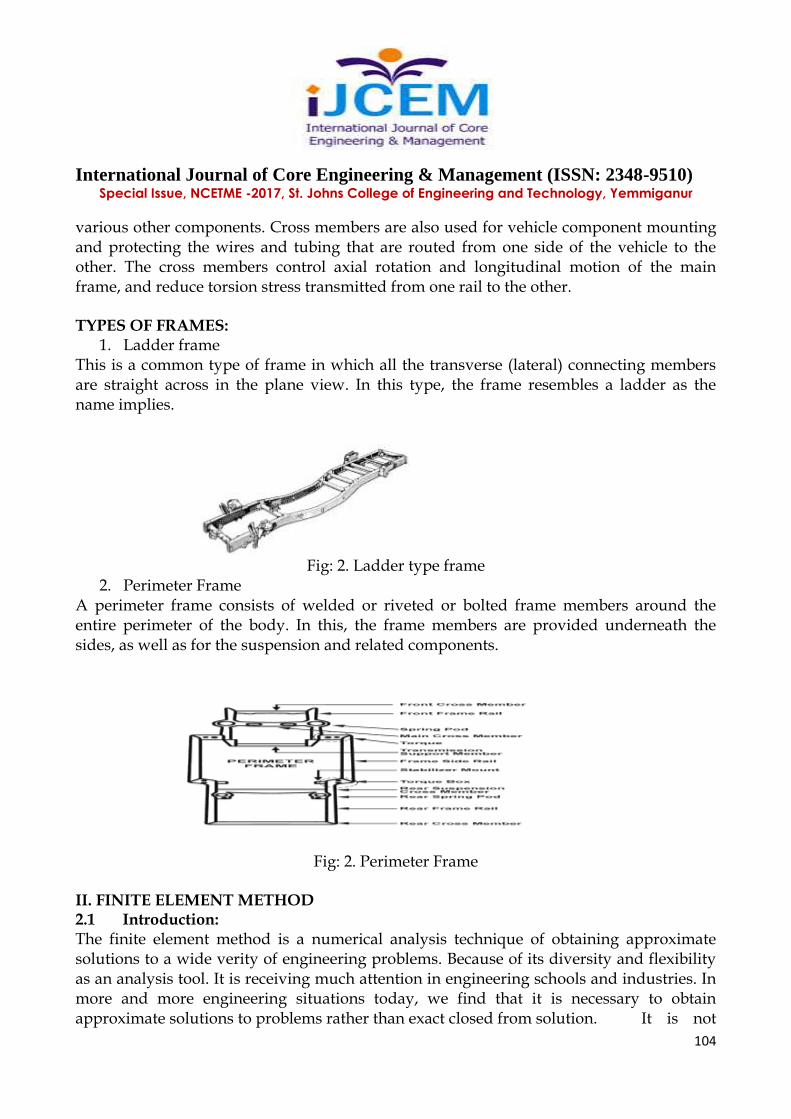
1. Ladder frame This is a common type of frame in which all the transverse (lateral) connecting members are straight across in the plane view. In this type, the frame resembles a ladder as the name implies.
Fig: 2. Ladder type frame 2. Perimeter Frame
A perimeter frame consists of welded or riveted or bolted frame members around the entire perimeter of the body. In this, the frame members are provided underneath the sides, as well as for the suspension and related components.
Fig: 2. Perimeter Frame
II. FINITE ELEMENT METHOD 2.1 Introduction: The finite element method is a numerical analysis technique of obtaining approximate solutions to a wide verity of engineering problems. Because of its diversity and flexibility as an analysis tool. It is receiving much attention in engineering schools and industries. In more and more engineering situations today, we find that it is necessary to obtain approximate solutions to problems rather than exact closed from solution. It is not

International Journal of Core Engineering & Management (ISSN: 2348-9510) Special Issue, NCETME -2017, St. Johns College of Engineering and Technology, Yemmiganur
105
possible to obtain analytical, mathematical solutions for many engineering problems. An analytical solution is a mathematical expression that gives the values of desired unkown quantity at any location in the body, as consequence it is valid for infinite number of location in the body for problems involving complex material properties and boundary conditions, the engineering study shifts towards numerical methods that provide approximate but acceptable solutions. The finite element method as become a powerful tool for the numerical solution of a wide range of engineering problems. It has developed simultaneously with the increase in use of the high speed electronic digital computers and with the growing emphasis on numerical methods for engineering analysis. The fundamental areas that have to be learned for working capability of FEM include: Matrix algebra Solid mechanics Variational methods Computer skills Matrix techniques are definitely most efficient and systematic way to handle algebra of finite element method. Basically matrix algebra provides a scheme by which a large number of equations can be stored and manipulated. Since vast majority of literature on the finite element method treats problem in structural and continuum mechanics, including soil and rock mechanics, the knowledge of these fields became necessary. It is useful to consider the finite element procedure basically basically as a variational approach.
2.2. General Description Of Fem: In the Finite element method, the actual continuum of body of matter like solid, liquid’ or gas is represented as an assemblage of sub divisions called Finite elements. These elements are considered to be interconnected at specified points known as nodes or nodal points. These nodes usually lie on the element boundaries where an adjacent element is consider to be connected. Since the actual variation of the field variables (like Displacement, stress, temperature, pressure and velocity) inside the continuum are is not known, we assume that the variation of the field variable inside a finite element can be approximated by a simple function. These approximating functions (also called interpolation models) are defined in terms of the values at the nodes. When the field equations (like: equilibrium equations) for the whole continuum are written, the new unknown will he the nodal values of the field variable. By solving the field equations, which are generally in the form of the matrix equations, the nodal Values of the field variables will he known. Once these are known, the approximating function defines the field variable throughout the assemblage of elements. The solution of a general continuum by the finite element method always follows as

International Journal of Core Engineering & Management (ISSN: 2348-9510) Special Issue, NCETME -2017, St. Johns College of Engineering and Technology, Yemmiganur
106
orderly step- by-step procedure for static structural problem can be stated as follows: Step 1: Descritization of structure (Domain) The first step in the finite element method is to divide the structure of solution region into sub divisions or elements. Step 2: Selection of proper interpolation model Since the displacement (field variable) solution of a complex structure under any specified load conditions cannot be predicted exactly, we assume some suitable solution with in a element to approximate the solution. The assumed solution must be simple and it should satisfy certain convergence requirements. Step 3: Derivation of element stiffness matrices (characteristics matrices) and load vectors: Front the displacement model the stiffness matrix [K (e)] and the load vector P (e) element are to be derived by using either equilibrium conditions or a suitable variation principle. Step 4: Assemblage of element to obtain the equilibrium equations: Step the structure is composed of several finite elements, the individual element stiffness matrices and load vectors are to be assembled in a suitable manner and the overall equilibrium equation has to be formulated as [K] F = P Where, [K] is called assembled stiffness matrix F is called the vector of nodal displacement and P is the vector or nodal force for the complete structure. Step 5: Solution of system equation to find nodal values of displacement (field variable) The overall equilibrium equations have to be modified to account for the boundary conditions of the problem. After the incorporation of the boundary condition, the equilibrium equations can be expressed as” [K] F = P For linear problems, the vector ‘F’ can be solved very easily. But for non-linear problems, the solution has to be obtained in a sequence of steps, each step involving the modification of the stiffness matrix [K] and ‘F’ or the 10,ad vector P Step 6: Computation of element strains and stress. From the known nodal displacements if required, the element strains and stresses can be computed by using the necessary equations of solid or structural mechanics in brackets implemented the general FEM step-by-step procedure.

International Journal of Core Engineering & Management (ISSN: 2348-9510) Special Issue, NCETME -2017, St. Johns College of Engineering and Technology, Yemmiganur
107
III.FEA SOFTWARE – ANSYS 3.1.Introduction To Ansys Program: ANSYS stands for analysis system product D.R. John Swanson founded Ansys inc in 1970 with vision to commercialize the concept-of computers simulated engineering establishing himself as one of the pioneers of finite element analysis (FEA). Ansys inc supports the ongoing development of innovative technology and delivers flexible, enterprise-wide engineering systems that enable companies to solve the full range of analysis problem, maximizing their existing investments software and hardware, Ansys Inc continues its role as a technological innovator. It also supports a process centric approach to design and manufacturing, allowing users to avoid expensive and time consuming “build and brake” cycles. Ansys analysis and simulation tools give customers ease of use, data capability, multi platform support and coupled field multi physics’ capabilities. 3.2 Evolution Of The Ansys Program: Ansys has evolved into multipurpose design analysis software program, recognized arrogant the world for its many capabilities. Today the program is extremely powerful and easy to use. Each release hosts new and enhanced capabilities that make the program more flexible more usable faster. In this way Ansys helps engineers meet the pressure and demands of the modern product development environment. 3.3.Overview Of The Program: The Ansys program is a flexible, robust design analysis and optimization package. The software operates on major computers and operating system, from pc to work stations to super computers, Ansys features file computability thought the family of products and across all platforms. Ansys design data accesses enables user to import computer aided design models in to ANSYS, eliminating repeat work. This ensures enterprise wide, flexible engineering solution for all Ansys user. User interface Although the Ansys program has extensive and complex capabilities, its organization and user friendly graphical user interface make it easy to learn and use. There are four general methods for instruction & the Ansys program: Menus Dialog boxes Tool bar Direct input of commands Menus Menus are groupings of related functions for operating the analysis program located in
International Journal of Core Engineering & Management (ISSN: 2348-9510) Special Issue, NCETME -2017, St. Johns College of Engineering and Technology, Yemmiganur
108
individual windows. These include: Utility menu Main menu Input window Graphics window Output window Tool bar Dialog boxes Utility Menu: It contains Ansys utility functions that are mapped here for access at any time during any Ansys session. These functions are executed through smooth, cascading pull down menus that lead directly to an action or dialog box. Main Menu: Comprise the primary Ansys functions, which are organized in pop-up side menus, based on the progression of the program. Input window: Provides an input area for typing Ansys commands and displays program prompt massages. Graphics window: Represents the area for graphic displays such as model or graphically represented results of an analysis. The user can adjust the size of the graphics window, reducing or enlarging it to fit to personal-preferences, Output windows: This window records the Ansys response to commands and functions. Tool bar: The tool represents a very efficient means for executing commands for the Ansys program because of its wide range of configurability. Regardless of how they are specified, commands are ultimately used to supply all data control all program function. Dialog boxes: These are the windows that present the user with choices for completing operations or specifying setting. These boxes prompt the user to input data or make decisions for a particular function.

International Journal of Core Engineering & Management (ISSN: 2348-9510) Special Issue, NCETME -2017, St. Johns College of Engineering and Technology, Yemmiganur
109
Processors: Ansys functions are organized into two groups called processors. The Ansys program has pre-processor, one solution processor, two post processors, and several auxiliary processors such as the design optimizer. The Ansys pre-processor allows the user to create a finite element model and to specify options needed for a subsequent solution. The solution processor is used to apply the loads and the boundary conditions, and then determine the response of the model to them. With the Ansys port processors, the user retrieves and examines the solution results to evaluate how the model responded, and to perform additional calculations of interest. Database: The Ansys program thus a single, centralized database for all model data and solution results. Model data (including solid model and finite element model geometry, materials etc) are written to the database using the processor. Loads and solution results data are written using the solution processor. Post processing results data are written using the post processors. Data written to the database while using one processor are therefore available, as necessary, in the other processors. File format: Files are used, when necessary, to pass the data from part of the program to another; to store the program the database and to store program output. These files include the database files, the result files, the graphics file, and so on. 3.4 .Procedure For Ansys Analysis: Static analysis is used to determine the displacements, stresses, strains and forces in structures is or components due to loads that do not induce significant inertia and damping effects. Steady loading in response conditions are assumed. The kinds of loading that call be applied in a static analysis include externally applied forces and pressures steady state inertial forces such as gravity or rotational velocity imposed (non zero) displacements, temperatures (for thermal strain). A static, analysis can be either linear or non linear. In our present work we are going to consider linear static analysis. The procedure for static analysis consists of these main steps: Building the model. Obtaining the solution. Reviewing the results. 3.4.1 Building The Model: In this step, we specify the job name and analysis title use PREP7 to define the element types, element real constrains, material properties and the model geometry element types both linear and non linear structural elements are allowed. The Ansys elements library

International Journal of Core Engineering & Management (ISSN: 2348-9510) Special Issue, NCETME -2017, St. Johns College of Engineering and Technology, Yemmiganur
110
contains over 80 different element types. A unique number and prefix identify each element type. Example: BEA0 94, PLANE 71, SOLID 96 & PEPE 16. Material Properties: Young’s modulus (Ex) must be defined for a static analysis. If we plan to apply inertia loads (such as gravity), we define mass properties such as density (DENS). Similarly if we plan to apply thermal loads (temperatures): we define coefficient of thermal expansion (ax). 3.4.2 Obtain The Solution: In this step we define the analysis type and options, apply loads and initial conditions the finite element solution. The following table shows the brief description of steps followed in each phase This involves three phases: Pre-processor phase Solution phase Post processor phase 3.4.2.1 Pre-Processor: Pre-processor has been developed so that the same program is available an micro, mini, super mini and main frame computer system. This allows easy transfer of models on one system to other. Pre-processor is an interactive model builder to prepare FE (Finite Element) model and input data. The solution phase utilizes the input data developed by the pre-processor; and dies the solution according to the problem definition. It creates input files to temperature etc., on the screen in the farm a centaurs. The following section describes various capabilities and features of the pre-processor Geometrical Definitions There are four different geometric entities in pre-processor namely key paints, lines, areas and volumes. These entities can be used to obtain the geometric representation of the structure. All the entities are independent of each other and have unique identification labels. Key Points: Key point (K P) is paint in 3-D space. A key paint is a basic entity and usually the first entity to be created. The key paints can be generated by many methods by individual definition, by transporting existing key points and from the other entities; e.g.., intersection of two lines, key paints at earners etc.,
International Journal of Core Engineering & Management (ISSN: 2348-9510) Special Issue, NCETME -2017, St. Johns College of Engineering and Technology, Yemmiganur
111
Line: A line is a general 3-D curve defined by using a parametric cubic equation. Lines can be generated from a number of grids. Sweeping a specified grid about axis through a desired included angle can generate a circular arc. Area: An area is a 3D surface defined using a parametric cubic equation. Area can be generated using four key points or four – line method, depending the geometry. Some inbuilt are as like circles, rectangles and polygons can be created to the required size. Volume: Volume is a general 3D solid region defined by using a parametric equation. Similar to areas, volumes also have parametric directions. Using two or four areas can generate these. Spinning an area about an axis can also generate volume (Sweep volumes): volumes of: Cylinder, torus; prism and sphere can be directly created to required dimension. Model Generation: Two different methods are used to generate a model Direct Generation Solid Modelling With solid modelling we can describe the geometric boundaries of the model established controls over the size and desired shape of the elements and then instruct the ANSYS program to generate all the nodes and elements automatically. By contrast, with the direct generation method, we determine the location of every node and size, shape and connectivity of every element prior to defining these entities in the ANSYS model. Although, some automatic data generation is possible (by using commands such as FILL,.NGEN, EGEN etc., the direct generation method is essentially a hands-on “Manual Method” but requires to keep track of all the node numbers as we develop the finite element mesh. This detailed book-keeping can become difficult for large models, giving scope for modelling errors. Solid modelling is usually more powerful and versatile than direct generation and is commonly the preferred method of generating a model. To judge which method is more suitable for a given solution, the relative advantages and disadvantages of two approaches are summarized as follow.. 3.4.2.2 Solution The solution phase deals with the solution or the problem according to the problem definitions. All the tedious work of formulating and assembling of matrices are done by the computer, and finally displacements and stress values are given as output. Some of the capabilities, ANSYS are linear static analysis, transient dynamic analysis etc.

International Journal of Core Engineering & Management (ISSN: 2348-9510) Special Issue, NCETME -2017, St. Johns College of Engineering and Technology, Yemmiganur
112
3.4.2.3 Post Processor It is powerful user-friendly post processing program. Using interactive colour graphics; it has extensive plotting features for displaying results obtained from the finite element analysis one picture of analysis results (i.e. results in a visual form) can often reveal in seconds what would take an engineer hour to asses from a numerical output, say in a tabular form. The engineer may also see important aspects of the results that could be easily missed in a stack of numerical data. Employing state of the art image enhancement techniques, facilities viewing of: Contours or stresses, displacements, temperatures, etc. Deform geometric plots. Animated deformed shapes. Time history plots. Solid sectioning. Hidden line plot Light source shaded plot. Boundary line plot etc. The entire range or post-processing option are different types of analysis can be accessed through the command/menu mode there by giving the user added flexibility and convenience.
VI. BACKGROUND INFORMATION
Fig: 7Deformed Shape At 14 Tonnes Fig: 8 Deformed Shape At 16tonnes
International Journal of Core Engineering & Management (ISSN: 2348-9510) Special Issue, NCETME -2017, St. Johns College of Engineering and Technology, Yemmiganur
113
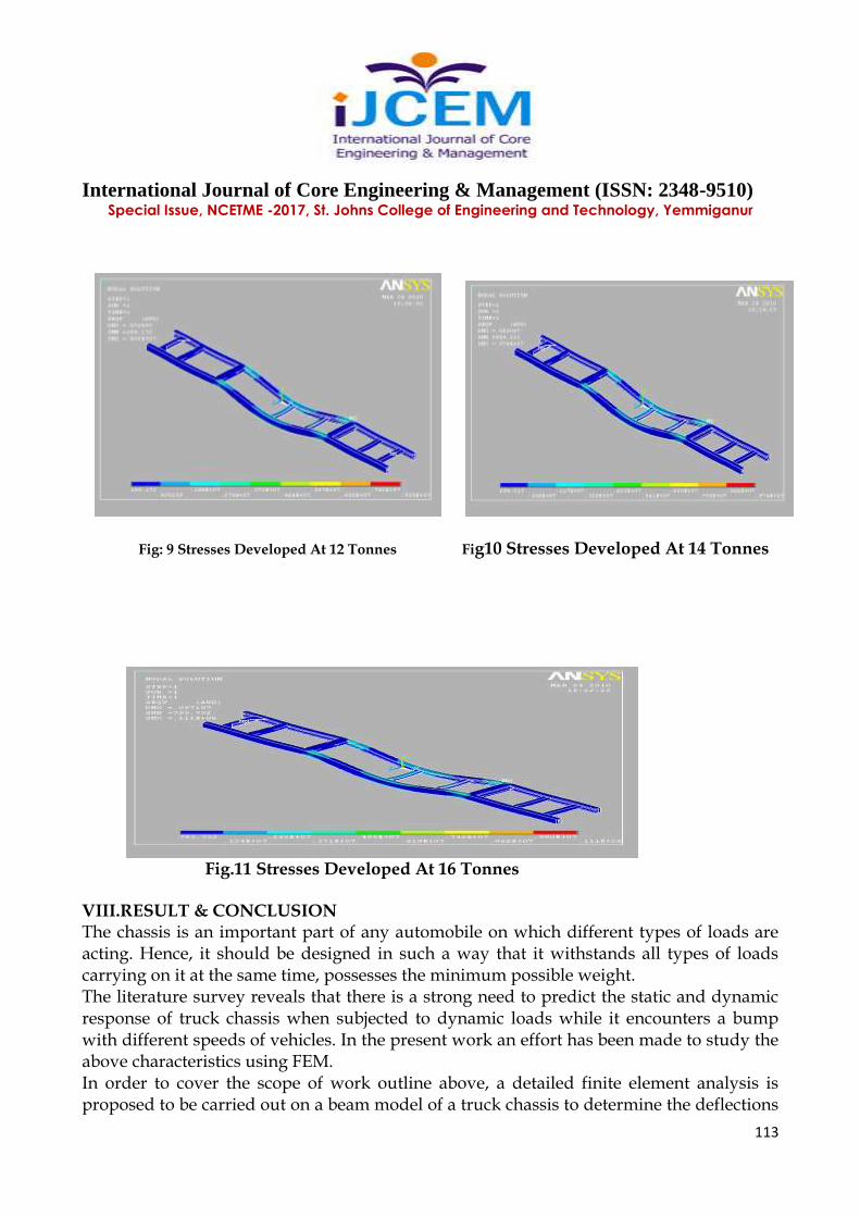
Fig: 9 Stresses Developed At 12 Tonnes Fig10 Stresses Developed At 14 Tonnes
Fig.11 Stresses Developed At 16 Tonnes VIII.RESULT & CONCLUSION The chassis is an important part of any automobile on which different types of loads are acting. Hence, it should be designed in such a way that it withstands all types of loads carrying on it at the same time, possesses the minimum possible weight. The literature survey reveals that there is a strong need to predict the static and dynamic response of truck chassis when subjected to dynamic loads while it encounters a bump with different speeds of vehicles. In the present work an effort has been made to study the above characteristics using FEM. In order to cover the scope of work outline above, a detailed finite element analysis is proposed to be carried out on a beam model of a truck chassis to determine the deflections

International Journal of Core Engineering & Management (ISSN: 2348-9510) Special Issue, NCETME -2017, St. Johns College of Engineering and Technology, Yemmiganur
114
and stresses in static conditions when the vehicle is on a bump using the analysis software ANSYS. Therefore from the results of deformations and equivalent stress analysis of chassis at various loaded conditions, the six wheeler chassis Frame is capable of withstanding to the loads up to 16 tonnes. REFERENCES 1.Roslan AbdRahman, MohdNasir “Stress Analysis of Heavy Duty Truck Chassis As a Preliminary Data Using FEM”, Tamin , Journal Mekanikal, December 2008, No.26, 76 85. 2.Teo Han Fui, RoslanAbd. Rahman” Statics And Dynamics Structural Analysis of a 4.5 Ton Truck Chassis,”Mechanical Engineering Dept., UniversitiTeknologi Malaysia, December 2007, No. 24, 56 –6756. 3.Zhanwang, Y., and Zongyu, C., “Dynamic Response Analysis of MinicarChangan Star 6350”, Proceedings of 2nd MSC worldwide automotive conference, MSC, 2000 4.Kim, H. S., Hwang, Y. S., Yoon, H. S., Dynamic Stress Analysis of a Bus Systems”,