international journal of heat and fluid flo ship/karabelas... · large eddy simulation of...
TRANSCRIPT

International Journal of Heat and Fluid Flow 31 (2010) 518–527
Contents lists available at ScienceDirect
International Journal of Heat and Fluid Flow
journal homepage: www.elsevier .com/ locate / i jhf f
Large Eddy Simulation of high-Reynolds number flow past a rotating cylinder
S.J. Karabelas *
National Technical University of Athens (NTUA), Department of Chemical Engineering, Computational Fluid Dynamics Unit, 157 80 Athens, Greece
a r t i c l e i n f o
Article history:Received 13 May 2009Received in revised form 15 January 2010Accepted 9 February 2010Available online 27 April 2010
Keywords:Magnus effectRotating cylinderLoad stabilityTurbulence
0142-727X/$ - see front matter � 2010 Elsevier Inc. Adoi:10.1016/j.ijheatfluidflow.2010.02.010
* Tel.: +306 977207390.E-mail addresses: [email protected], stkarabe
a b s t r a c t
In the present study, uniform flow past a rotating cylinder at Re = 140,000 is computed based on LargeEddy Simulation (LES). The cylinder rotates with different spin ratios varying from a = 0 to a = 2, wherea is defined as the ratio of the cylinder’s circumferential speed to the free-stream speed. The Smagorinskymodel is applied to resolve the residual stresses. The present commercial code is validated based on avail-able numerical and experimental data. The results agreed fairly well with these data for the cases of theflow over a stationary and over a rotating cylinder. As the spin ratio increases, the mean drag decreasesand the mean cross-stream force acting to the cylinder increases. The vortices (time-averaged) down-stream of the cylinder are displaced and deformed and the vortex that is close to the region of the fluid’sacceleration shrinks and eventually collapses. By increasing a, the flow is also stabilized. It is observedthat the vortex shedding process is suppressed. Specifically, the flow is unstable in load terms for spinratios up to 1.3. After this critical value, the flow is transitional for a few dimensionless time units dem-onstrating the well-known von-Karman vortex street and then it becomes stable with almost constantloads. An encouraging outcome resulting from this study is that the LES computations could be accuratefor high-Re sub-critical flows with grids of medium resolution combined with a validated sub-grid scalemodel and a low-diffusive discretization scheme.
� 2010 Elsevier Inc. All rights reserved.
1. Introduction the domain. The results were quite different from those of Breuer
Bluff body flows have been the target of study for many scientists,since the physics of these flows is very complex and they require spe-cial attention to their modelling and numerical solution. They arealso ideal cases for the validation of different approaches to turbu-lence modelling. One of these is Large Eddy Simulation (LES), a prom-ising technique that has recently started to gain popularity even forhigh-Re flows. However, it is well known that for high-Re regimes thesub-grid-scale and the near-wall modelling become crucial for theaccuracy of the computations. In cylinder flows, the results are notvery promising for super-critical Re numbers, at least based on thepreliminary study by Catalano et al. (2003) who assessed the validityof LES with near-wall modelling for a flow past a circular cylinder upto Re = 2 � 106. Their results departed significantly from those re-ported in experiments. Nevertheless, they stated that their study isat a preliminary stage and no well-justified conclusions could bedrawn. In contrast, the numerical results for sub-critical but stillhigh-Re flows past a cylinder are satisfactory. Breuer (1999, 2000)conducted relevant studies at Re = 140,000, where he found suffi-cient agreement with the well-organized experiment of Cantwelland Coles (1983). Elmiligui et al. (2004) studied the same problemat Re = 50,000 and Re = 140,000, but the free-stream flow was notlaminar. Medium turbulence intensity was imposed on the inlet of
ll rights reserved.
(2000) in terms of the drag coefficient and Strouhal number, but theyagreed well with the numerical experiments of Travin et al. (2000)and Hansen and Forsythe (2003), who used relevant boundary andinitial conditions.
The above studies cited in the open literature refer to the mod-elling of the flow past a stationary cylinder for high-Re numbers.The more challenging case of the flow past a rotating cylinderhas not yet been investigated extensively. In the laminar regimestwo highlighted studies are those of Mittal and Kumar (2003)and Padrino and Joseph (2006). The Re number based on the diam-eter of the cylinder and the free-stream flow is 200 in the firststudy and 200, 400 and 1000 in the latter study. In the context ofthese articles, the physics of the laminar flow past a spinning cyl-inder is analysed for various spin ratios whereas the lift, drag andpressure coefficients are computed. The well-known Magnus effectis examined in this framework and the results (for the lift force) arecompared with those of potential flow (Zdravkovich 1997). Aninteresting study of Stojkovic et al. (2002) has been also found inthe literature, in which high rotation rate effects to the mean loadsare investigated. The values of a varied from 0 to 12 and the char-acteristic Re number based on the diameter of the cylinder was100. Many additional results have been obtained, including thefrequencies of the wake instability and the distinct changes ofthe flow structure. The load stability of laminar flows has also re-ceived considerable attention. It has been generally found in thepreceding studies that the rotational effects suppress the vortex

S.J. Karabelas / International Journal of Heat and Fluid Flow 31 (2010) 518–527 519
shedding activity at a specific range of spin ratio. More specificallyat Re = 200 it is universally accepted that for ð1:91 6 a 64:4Þ
Sa > 4:8, where a is defined as a ¼ Uh
U1with Uh being the cir-
cumferential velocity and U1 the free-stream velocity, the flow be-comes steady (Mittal and Kumar (2003)). Analogous conclusionshave been reached in the detailed study of Stojkovic et al. (2003).They confirmed the existence of the second vortex shedding modefor the entire Reynolds number range 60 6 Re 6 200 and a com-plete bifurcation diagram a(Re) was presented. A well-organizednumerical study was also published by Ingham (1983). In that pa-per, the Navier–Stokes equations were solved via the finite differ-ence method in order to examine the asymmetrical flow in uniformviscous liquid at Re numbers 5 and 20 and dimensionless ratio afrom 0 to 0.5. Kang et al. (1999) also contributed significant workto this research area. Sequential numerical simulations at Re equalto 40, 60, 100 and 160 in the range of 0 6 a 6 2.5 were performed.They observed that at 60 6 Re 6 160 the maximum value of a,which favours flow instability varies logarithmically when plottedagainst the Re number.
In transitional or fully turbulent flows analogous conclusionshave not been reached, at least, to the author’s knowledge. Thereare two research articles that examine rotating cylinder flows athigh-Re numbers and spin ratios up to 1. These are the studies ofAoki and Ito (2001) and Elmiligui et al. (2004). For values greaterthan 1, the present study might be the first attempt to resolvethe flow phenomena.
The objective of the present research work is to resolve thephysics of the flow past a spinning cylinder for ratios up to 2 atRe = 140,000. Besides the computation of the integral coefficientsand the statistics of turbulence, load stability has been studiedfor the above range of a and a new ‘limit’ for wake stability hasbeen established.
2. Computational grid and numerical modelling
The 3-D incompressible time-dependent viscous Navier–Stokesequations are solved via the finite- volume code FLUENT 6.3, whichis compatible with multi-block structured grids. The computationsare performed in a single computer without any parallelization or
Fig. 1. Computational domain (side section) and the system of reference for the numecylinder rotates in the counter-clockwise direction. A panoramic and a close-up view of
domain decomposition. The equations are discretized in space bythe low-diffusive central differencing scheme of second orderaccuracy. Temporal discretization is fully implicit and second orderaccurate for all the present computations. Within every time step,the Poisson equation for the pressure correction is formulated bythe PISO velocity–pressure coupling scheme and is solved by apoint implicit Gauss–Seidel iteration, which is accelerated by analgebraic multi-grid method (AMG). Sub-grid scale modelling isbased on the Smagorinsky model (Smagorinsky, 1963) with a‘wall-sensitive’ length-scale defined as ls ¼minðkd;CsV
13Þ, where k
is the von-Karman constant, d is the distance from the wall, Cs
the Smagorinsky constant (equal to 0.1 in the present study) andV the volume of the cell.
The dimensionless time step dt0 ¼ dt U1D is chosen to be 10�3,
where U1 is the free-stream velocity and D the diameter of the cyl-inder. This value fulfils the accuracy requirement (and stabilityrequirement for explicit solvers) CFL 6 1 and it is also chosenbased on the values cited in relevant research articles (Breuer,2000; Catalano et al., 2003). The grid size is quite thin close tothe cylinder and it is capable of resolving most of the developedboundary layer, thus any wall functions did not apply (yþ < 5 atall spin ratios).
A single curvilinear (body-fitted) O-type grid (Fig. 1) based onthe study of Padrino and Joseph (2006) is used for all the computa-tions. In the cross-sectional plane 125 � 125 grid points are used,while in the spanwise direction 32 points are distributed uni-formly. The entire domain has a radial extension of L = 20D whichappears to be a proper choice according to the preliminary compu-tations of Breuer (1998). The spanwise extension was carefullychosen to be Z = D based on the study of Breuer (1999) who as-sessed the influence of the spanwise extension on the LES compu-tations of the flow past a circular cylinder at Re = 140,000.Although the spanwise length of one cylinder diameter may notbe capable of resolving all the turbulent structures, it is revealedin the latter study that the results for Z = D agree fairly well withrelevant experimental data and on some occasions the resultsmatch even better with experiments than for Z = 2D. In the presentstudy this is verified below. Moreover, the computational timeneeded to converge statistically the results is at least four times
rical simulations. The azimuth angle h is measured in a clockwise way while thethe structured grid adopted are also presented.

520 S.J. Karabelas / International Journal of Heat and Fluid Flow 31 (2010) 518–527
less than using a grid with double spanwise length with cells of thesame aspect ratio (non-elongated cells). However, it has to be men-tioned that based on the studies of Breuer (1999, 2000), this valueof the spanwise length reduces the drag coefficient roughly 20%and increases the separation angle by 1–3�.
Fig. 2. Time-averaged dimensionless stream-wise velocity along the centreliney = 0: Breuer’s results, present results and the experimental measurements ofCantwell and Coles (1983).
3. Description of the test cases and validation of the code
The present study investigates the rotational effects induced bythe no-slip condition on the cylinder’s surface at Re = 140,000. Thechoice of this number was intentional, because at this value of Re,experimental and numerical data were available from the litera-ture. The spin ratio of the cylinder a ¼ Uh
U1, varies from 0 to 2. Close
to the value, which was firstly observed to produce load stability, itwas necessary to perform more runs in order to indicate as pre-cisely as possible the ‘limit’ where the wake instability is stronglysuppressed.
Two symmetry boundary conditions are applied far away fromthe cylinder (S1: 85:8 6 h 6 94:2) and (S2: 265:8 6 h 6 274:2) asshown in Fig. 1, a velocity inlet condition ‘free of turbulence inten-sity’ is prescribed to the region on the left (I: �85:8� 6 h 6 85:8�) ofthe domain and a zero stream-wise gradient ‘outflow’ condition tothe region on the right (O: 94:2� 6 h 6 265:8�). Periodicity of theflow is assumed in the spanwise direction. The cylinder rotatesin the counter-clockwise direction, thus the no-slip condition~U ¼ aU1
R
� �~z�~rðx; yÞ is imposed on the cylinder’s surface (C).
The present study is concerned with a high-Re regime wheretransition to turbulence occurs inside the thin shear layer just afterthe line of separation. Since available data exist for the non-rotat-ing case, it is considered necessary to validate the implementedcode. This is carefully done by comparing the present results withthose of Breuer (2000) and the measurements of Cantwell andColes (1983). At this Re number the flow is turbulent and statisti-cally non-stationary. The fluid accelerates up to the middle of thecylinder and then the laminar boundary layer separates. After ashort time the shear layer becomes turbulent and, on each sideof the cylinder. Both separated shear layers are quite unstableforming the commonly-observed vortex shedding pattern down-stream. It appears from the cited studies and the present resultsthat the flow is statistically symmetric. Table 1 summarizes the re-sults of a collection of simulations by Breuer (2000), the measure-ments from the experiments of Wieselsberger et al. (1923) and themeasurements of Cantwell and Coles (1983). It has to be acknowl-edged that in the experiments there are several parameters whichsignificantly influence the measurements both locally and globally.The most important are the blockage ratio, the aspect ratio of thecylinder, the turbulence intensity of the free-stream flow (whichis always non zero for all the experiments), the end conditions,the roughness of the model, the accuracy of any implemented vir-tual balance devices or hot-wire anemometry equipment and theprecision of the calibration model used for the computation ofthe loads. It becomes obvious that differences arise between theset-up of the numerical modelling and the experimental condi-tions, even for the most carefully prepared experiment. Neverthe-
Table 1Experimental and numerical results in the literature compared to the present ones.
Grid SGS model
Present 125 � 125 � 32* Smag. Cs = 0.1Breuer (2000) 165 � 165 � 64* Smag. Cs = 0.1Breuer (2000) 325 � 325 � 64* Smag. Cs = 0.1Cantwell and Coles (1983) (exp.) –Wieselsberger et al. (1923) (exp.) –
* All computations have been done for spanwise length Z = D.** Angle corresponds to the appearance of the inflexion point.
less, a quite clear picture for the evaluation of the presentnumerical results could be drawn from the cited experiments.
From Table 1, it may be concluded that the numerical andexperimental results are in good agreement. The Strouhal numberconverges to 0.2 except for the experiment of Cantwell, which isunder-predicted. The back-pressure coefficient and the angle ofseparation agree fairly well in the numerical simulations. However,in the experiment the reported angle is measured with respect tothe appearance of the inflexion point and it is lower than the sep-aration angle, thus a direct comparison could not be made. Thedrag coefficient is close to the other numerical computations buta difference is observed with the experiments.
A more qualitative evaluation of the present results may be ob-tained by comparing them with other data in terms of the time-averaged and spanwise-averaged velocity fields. Fig. 2 providesthe dimensionless stream-wise velocity profile at the symmetryline y = 0. The present results appear to over-predict the lengthof the recirculation area and the magnitude of the reversed velocitywith respect to the cited results of Breuer (2000). In the near-mid-dle and far wake, the present computations agree quite well withthe experimental measurements. Unfortunately, no experimentalevidence exists for the velocity profile in the vicinity of the cylin-der. In Fig. 3, the computed dimensionless normal velocity V at aconstant x-position x = D in the near wake almost coincides withthe numerical data of Breuer (2000) and is slightly under-predictedcompared to the measurements of Cantwell and Coles (1983).
Second-order moments have been also investigated, includingthe variance of the normal fluctuations hvvi and the Reynoldsshear stress huvi. Before this topic is discussed, some theoreticalremarks should be made. The flow over a cylinder at sub-criticalregimes is strongly unsteady due to the strong vortex – sheddingwhich occurs behind the cylinder. The vortex shedding is accompa-nied by turbulent fluctuations and, therefore, the computed flow
Cd Cpeak St Hsep. (�)
1.03 �1.19 0.22 96.900.97 �1.08 0.23 96.601.05 �1.22 0.19 93.621.23 �1.21 0.18 >77**
�1.20 �0.2

Fig. 3. Time-averaged dimensionless normal velocity at x = D: Breuer’s results,present results and the experimental measurements of Cantwell and Coles (1983).
Fig. 5. Total resolved dimensionless shear stress at x = D: Breuer’s results, presentresults and the experimental measurements of Cantwell and Coles (1983).
S.J. Karabelas / International Journal of Heat and Fluid Flow 31 (2010) 518–527 521
variables are often decomposed into three instead of the traditionaltwo components: the time-averaged mean value, the periodiccomponent and the turbulent fluctuation. In order to separatethe effects of the two latter components, phase-averaging is neces-sary. However, in the present study, no phase-averaging has beenperformed, therefore, the Reynolds stresses are composed of the‘periodic’ and the ‘turbulent’ component.
In Fig. 4, the dimensionless mean-square fluctuation of thenormal velocity, denoted hvvi is plotted at y = 0. The present LESresults appear to converge better than Breuer’s (2000) computa-tions with the measurements. Close to the cylinder’s surface thereis a large difference between the numerical data and the measuredvalue regarding the location of the peak value of hvvi. From thisfigure it is seen that the cited numerical data overestimate hvviand the peak value is found to be farther from the rear of the cyl-inder. In the near and far wake the present results agree well withthe measurements. An astonishing conclusion reported in Breuer’s(2000) study was that grid refinement did not lead to closer agree-ment between the numerical results with the measurements andin some cases the differences became greater. This was also thecase when the second-order moment huvi is plotted at x = D,Fig. 5. The present results agree well with respect to the maximumvalues and their positions obtained from the measurements. Nev-ertheless, they are distributed differently over the suction side.
Fig. 4. Mean dimensionless square fluctuations of the normal velocity at y = 0:Breuer’s results, present results and the experimental measurements of Cantwelland Coles (1983).
The other numerical results over-predict the turbulent shear stressbut they are distributed more consistently. It is also confirmed forthe latter numerical computations that their results for the finergrid deviate more from the experimental measurements of Cant-well and Coles (1983). Explanations for this unexpected trend areoffered in the same study of Breuer (2000).
The deviations between the present numerical data and Bre-uer’s data are attributed mainly to the different near-wall grid res-olution, the use of a different damping function for theSmagorinsky length-scale and, possibly, slightly to the differentcross-sectional area. The differences with the experimental dataare observed for several reasons. In the context of a numerical sim-ulation it is not possible to simulate exactly the experimental con-ditions. In the present case, there are many major differencesbetween the set-up of the numerical and the experimental process.The most important are the different spanwise length of the cylin-der and the different turbulence level at the inflow (see Cantwelland Coles, 1983; Breuer, 2000). The above parameters suffice toproduce discrepancies between the numerical and the experimen-tal results.
4. Results and discussion
4.1. Basic flow physics
The physics of the turbulent flow over a rotating cylinder isquite different from that over a stationary cylinder. It is not alwaysmore complex as it might be expected. Before proceeding to thequantitative results of this study it is convenient to present thegeneral flow features of rotating cylinder flows at Re = 140,000. Ini-tially, five spin ratios were investigated and then three additionalruns were performed to examine the flow stability. In Fig. 6, thestreamlines of the time-averaged and spanwise-averaged velocityfields are displayed. For the non-rotating case, in accordance withthe experimental data, the computations predict an attached recir-culation region downstream of the cylinder. The separation angle isfound to be 96.9�, thus the flow separates after the apex of the cyl-inder. Two smaller counter-rotating vortices are observed on thedownstream side of the cylinder, in contrast to the results of Bre-uer (2000). A possible explanation for this difference could be theimplementation of a different length-scale (close to the walls) inthe Smagorinsky model (which was the Van Driest damping func-tion in the latter study). In an attempt to identify the cause of theabove difference, an extra run at Re = 140,000 and at a = 0 was per-formed using the dynamic model, Germano et al. (1991). The

Fig. 6. Streamlines of time-averaged velocity fields for spin ratios ranging from a = 0 to a = 2.
522 S.J. Karabelas / International Journal of Heat and Fluid Flow 31 (2010) 518–527
streamline results are found to be almost identical with those onesof the classical Smagorinky model, thus the use of a differentdamping function does not explain the different flow patterns.Based also on the fact that the solution method is the same andboth grids are quite similar, a convincing explanation could notbe given.
Different patterns are observed when the cylinder rotates (inthe counter-clockwise direction). Generally speaking, the rotatingfluid driven by the motion of the cylinder is superimposed on thefree-stream flow on the lower surface (260� < h < 340�). This nat-urally leads to a global increase of the fluid’s velocity. In the region(20� < h < 100�) the rotating fluid opposes the free-stream flow.This effect retards the outer flow which actually slides over fluidmoving in the opposite direction and, as will be shown this triggersthe deflection of the outer flow towards the transverse directionand allows the rotating boundary layer (RBL) to dominate thedownstream side of the cylinder. For a = 0.5, the no-slip conditiondoes not induce large circumferential velocities in the vicinity ofthe cylinder. Over the front and upper part the RBL develops onlyin the viscous sub-layer. Correspondingly, the pair of vorticesdownstream of the cylinder is asymmetric. The lower vortex con-tracts while the upper one is little enlarged. In the south area theRBL energizes the free-stream flow which remains attached tothe cylinder, thus no separation occurs on the lower side (thelow pressure side) of the cylinder and the vortex is formed at aconsiderable distance from the wall. Over the upper region of thecylinder the gradual development of the RBL causes the bulk ofthe outer flow to move transversely and it consequently formsthe upper vortex structure. On the rear side the RBL develops freewith the slight effect of the recirculating fluid which had been pre-viously deflected. Similar conclusions may be drawn for a = 1. Thecircumferential velocities in the viscous sub-layer are comparablewith the magnitude of the free-stream velocity and the effectsare stronger than in the previous case. The outer flow quicklymoves transversely, allowing the formation of a large upper vortex.
The bottom vortex is slightly larger than in the previous case. Thesystem of both vortices is asymmetric but it is also rotated coun-ter-clockwise with respect to the x (longitudinal) axis. The frontstagnation point is evidently displaced by approximately at h = 10�.
As the spin ratio further increases, the bottom vortex shrinksand the upper expands. The front stagnation point moves azimuth-ally to greater h and the flow beneath the lower surface of the cyl-inder approaches the classical flow induced by pure rotation. Thecase a = 2 is of particular interest. It is clear that the RBL is signif-icantly stronger than the mean magnitude of the free-streamvelocity. The stagnation point is displaced to h = 28� and is dis-placed away from the wall. Beyond this value of the azimuthal an-gle, the outer flow slides over a quite thick fluid layer which movesin the opposite direction. The resulting upper vortex is not as largeas expected, but it is slenderer than in the previous cases. The low-er vortex has collapsed. A possible explanation for this, might bethe combined action of the position of the upper vortex and thehigh momentum of the fluid coming from the lower side of thecylinder.
4.2. Mean loads and higher order moments
Rotational effects greatly modify the loads exerted by the fluidon the cylinder. Lift and drag coefficients are plotted for variousspin rates in Fig. 7 and compared with the computations of Aokiand Ito (2001) and some available experimental data (publishedin the same study). Also some laminar data at Re = 40 andRe = 160 have been selected from the study of Kang et al. (1999)and the results of the potential theory are also presented in thesame figure for further comparison and discussion.
The lift force is generated by to the acceleration of the fluid be-neath the cylinder and its deceleration above it (for counter-clock-wise rotation). It is seen that the lift increases linearly with a forlow spin ratios, whereas for higher values it increases more stee-ply. The results agree quite well with Aoki’s computations,

Fig. 7. Lift and drag coefficient versus spin ratio: Aoki and Ito (2001) results atRe = 60,000, present results at Re = 140,000 and the experimental measurements ofAoki and Ito (2001) at Re = 60,000.
Fig. 8. Pressure coefficient Cp computed along the cylinder’s surface for differentspin ratios. For all the cases the convention Cp = 1 at h = 0� is adopted.
S.J. Karabelas / International Journal of Heat and Fluid Flow 31 (2010) 518–527 523
although the Re number is not the same. The drag coefficient re-duces as a increases because the upstream stagnation point isshifted azimuthally from the longitudinal direction (x-axis) andthe magnitude of the pressure drag, which is the main contributorto the drag coefficient, decreases. This reduction in drag is counter-balanced by an increase in lift. The results for the mean drag coef-ficient are quite satisfactory when compared with the experimen-tal measurements. Differences did not exceed 10% of the nominalvalues. The under-estimation of the mean drag coefficient is attrib-uted to the modest spanwise length of the domain (one diameter).
Interesting conclusions may be drawn from the comparing be-tween the laminar and turbulent cases, which is examined in thisfigure. It is clear from Fig. 7 that the spin ratio generally affectsthe forces applied to the cylinder in a similar manner, no matterwhether the flow is turbulent or laminar. However, some differ-ences are apparent. It appears that the lift coefficient in the laminarcase increases at a comparable rate on average as for turbulentflow, but the value of Cl in laminar is higher. It is also observed thatfor high a the differences between the laminar and turbulent val-ues of Cl and Cd diminish. The drag coefficient in the laminar re-gime is greater for all a and its reduction is steeper at Re = 160.The basic reason for these differences is that the laminar patternsare quite different from the turbulent ones. In laminar flows, thestagnation point usually lies further from the cylinder’s surfaceand is located at different circumferential locations positions thanin the turbulent regime, thus the static pressure distribution isgreatly different. Other important factors could be the high separa-tion angle and the increasing friction drag, when turbulence ispresent.
In Fig. 8, the mean pressure coefficient is plotted for variousspin ratios. The reference pressure p1 satisfies the conditionCp = 1 at h = 0� and a = 0, while for higher values of a the stagnationpoint moves accordingly. The reduction of the static pressure onthe lower side is clearly evident where the pressure coefficient ex-ceeds the value of �6 (the azimuthal angle is measured anti-clock-wise rather than the convention indicated in Fig. 1). The position ofthe minimum Cp is displaced towards the lower surface as the spinratio increases. Similarly, the position of the maximum Cp valuemoves towards the upper surface as a increases. The pressure coef-ficient peaks at the stagnation point, which can reach significantlyhigher values (in terms of the azimuthal angle) than the zero one ata = 0; thus, the maximum value of the azimuthal angle is approxi-mately h = 28� at a = 2 (in the diagram the angle is 332�).
For a more detailed investigation of the turbulence field devel-oped, second-order moments are examined. As has already beennoted, these moments are the sum of the periodic vortex shedding(low-frequency) oscillations plus the random turbulent (high-fre-quency) fluctuations. In Fig. 9, the total resolved kinetic energy ofthe fluctuations kf ¼ 0:5 hu2i þ hv2i þ hw2i
� �is presented. Strictly
speaking kf is equal to the turbulent kinetic energy. However, theturbulent kinetic energy is commonly understood to be the prod-uct of the turbulent fluctuations and excluding any other oscilla-tions, which are produced by wake instabilities. Thus, thedefinition above is used specifically to distinguish the turbulent ki-netic energy (energy produced by high-frequency disturbances)from the total resolved kinetic energy of fluctuations kf.
In the case of the stationary cylinder, the energy reaches a max-imum downstream of the cylinder at x = 1.3D. The major fraction ofthis energy is attributed to the strong vortex shedding oscillationsrather than the turbulent fluctuations. In the same plot, the pointof transition to turbulence appears to lie downstream of the sepa-ration point. For greater spin ratios, the region of maximum energyis shifted upwards forming an angle with the longitudinal axis. Fora = 0.5 and a = 1.0, the flow becomes turbulent both at lower azi-muthal angles than h = 90� and close to the point where the free-stream flow is deflected from the surface of the cylinder (seeFig. 6). The values of kf at these azimuthal angles are computedal solely on the turbulent fluctuations since there is no contribu-tion from vortex shedding there. Careful inspection shows thatfor spin ratios greater than one the downstream region attachedto the cylinder is entirely turbulent. In contrast, for lower a, lami-nar areas could be observed.
The case of the highest spin ratio, a = 2, considered in more de-tail. The region of maximum kf is close to the upper surface. As willbe seen later, at this rotation rate the vortex shedding is stronglysuppressed after a short dimensionless time. Therefore, the totalresolved kinetic energy of the fluctuations is composed mainly ofthe energy derived from the turbulent fluctuations. On this occa-sion, the flow appears to be highly turbulent close to the cylinder’ssurface. On the other hand, for lower ratios the contribution of theperiodic oscillations to kf prevails. It also appears from this figurethat the total resolved kinetic energy of the fluctuations decreasessignificantly with a. However, the turbulent kinetic energy in-creases with the spin ratio since higher vorticity values are ob-served close to the upper surface. The explanation for this resultis closely related to the stability of these flows. As will be seen inthe next section, the vortex shedding is gradually suppressed andit is possible that for high values of a it would be diminished.The effects are straightforward for the distribution of the kineticenergy. As a increases, the periodic oscillations are damped and
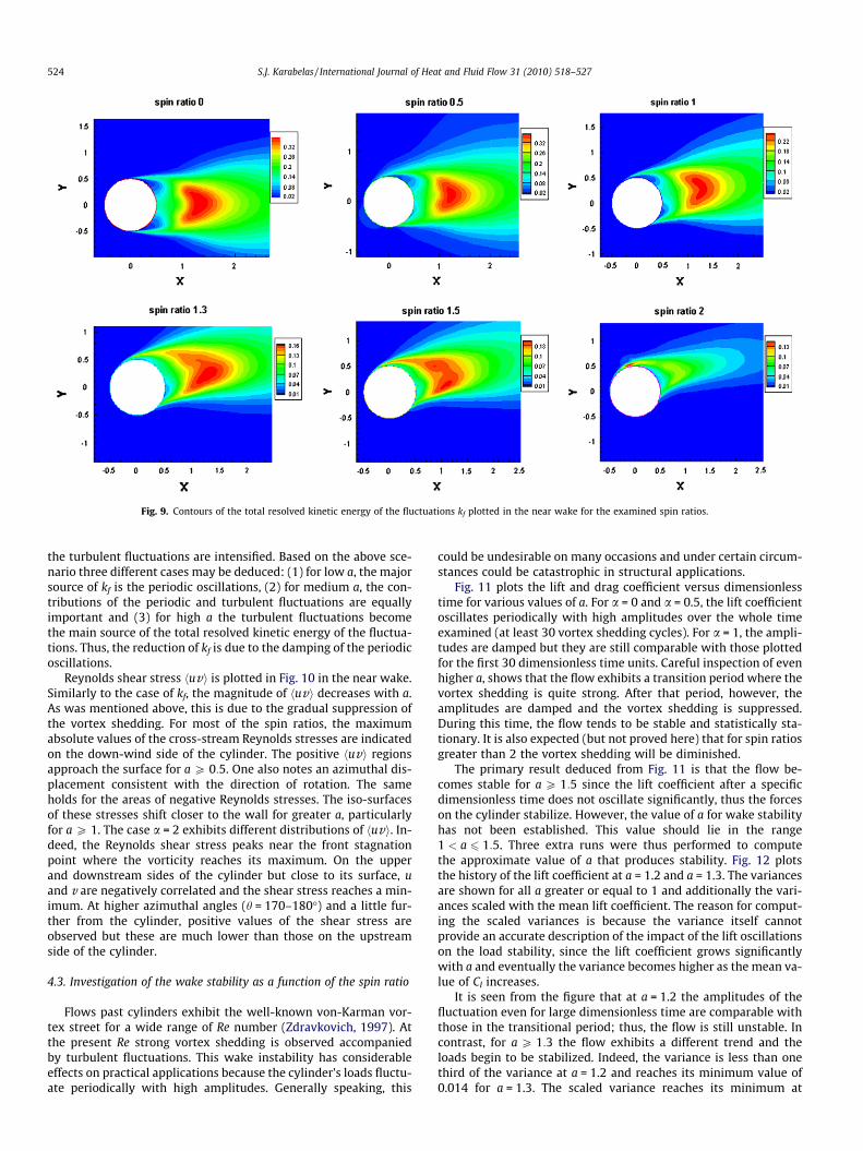
Fig. 9. Contours of the total resolved kinetic energy of the fluctuations kf plotted in the near wake for the examined spin ratios.
524 S.J. Karabelas / International Journal of Heat and Fluid Flow 31 (2010) 518–527
the turbulent fluctuations are intensified. Based on the above sce-nario three different cases may be deduced: (1) for low a, the majorsource of kf is the periodic oscillations, (2) for medium a, the con-tributions of the periodic and turbulent fluctuations are equallyimportant and (3) for high a the turbulent fluctuations becomethe main source of the total resolved kinetic energy of the fluctua-tions. Thus, the reduction of kf is due to the damping of the periodicoscillations.
Reynolds shear stress huvi is plotted in Fig. 10 in the near wake.Similarly to the case of kf, the magnitude of huvi decreases with a.As was mentioned above, this is due to the gradual suppression ofthe vortex shedding. For most of the spin ratios, the maximumabsolute values of the cross-stream Reynolds stresses are indicatedon the down-wind side of the cylinder. The positive huvi regionsapproach the surface for a P 0:5. One also notes an azimuthal dis-placement consistent with the direction of rotation. The sameholds for the areas of negative Reynolds stresses. The iso-surfacesof these stresses shift closer to the wall for greater a, particularlyfor a P 1. The case a = 2 exhibits different distributions of huvi. In-deed, the Reynolds shear stress peaks near the front stagnationpoint where the vorticity reaches its maximum. On the upperand downstream sides of the cylinder but close to its surface, uand v are negatively correlated and the shear stress reaches a min-imum. At higher azimuthal angles (h = 170–180�) and a little fur-ther from the cylinder, positive values of the shear stress areobserved but these are much lower than those on the upstreamside of the cylinder.
4.3. Investigation of the wake stability as a function of the spin ratio
Flows past cylinders exhibit the well-known von-Karman vor-tex street for a wide range of Re number (Zdravkovich, 1997). Atthe present Re strong vortex shedding is observed accompaniedby turbulent fluctuations. This wake instability has considerableeffects on practical applications because the cylinder’s loads fluctu-ate periodically with high amplitudes. Generally speaking, this
could be undesirable on many occasions and under certain circum-stances could be catastrophic in structural applications.
Fig. 11 plots the lift and drag coefficient versus dimensionlesstime for various values of a. For a = 0 and a = 0.5, the lift coefficientoscillates periodically with high amplitudes over the whole timeexamined (at least 30 vortex shedding cycles). For a = 1, the ampli-tudes are damped but they are still comparable with those plottedfor the first 30 dimensionless time units. Careful inspection of evenhigher a, shows that the flow exhibits a transition period where thevortex shedding is quite strong. After that period, however, theamplitudes are damped and the vortex shedding is suppressed.During this time, the flow tends to be stable and statistically sta-tionary. It is also expected (but not proved here) that for spin ratiosgreater than 2 the vortex shedding will be diminished.
The primary result deduced from Fig. 11 is that the flow be-comes stable for a P 1:5 since the lift coefficient after a specificdimensionless time does not oscillate significantly, thus the forceson the cylinder stabilize. However, the value of a for wake stabilityhas not been established. This value should lie in the range1 < a 6 1:5. Three extra runs were thus performed to computethe approximate value of a that produces stability. Fig. 12 plotsthe history of the lift coefficient at a = 1.2 and a = 1.3. The variancesare shown for all a greater or equal to 1 and additionally the vari-ances scaled with the mean lift coefficient. The reason for comput-ing the scaled variances is because the variance itself cannotprovide an accurate description of the impact of the lift oscillationson the load stability, since the lift coefficient grows significantlywith a and eventually the variance becomes higher as the mean va-lue of Cl increases.
It is seen from the figure that at a = 1.2 the amplitudes of thefluctuation even for large dimensionless time are comparable withthose in the transitional period; thus, the flow is still unstable. Incontrast, for a P 1:3 the flow exhibits a different trend and theloads begin to be stabilized. Indeed, the variance is less than onethird of the variance at a = 1.2 and reaches its minimum value of0.014 for a = 1.3. The scaled variance reaches its minimum at
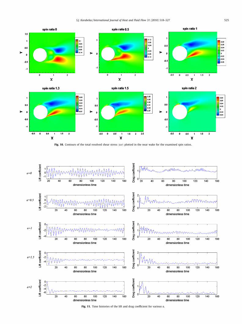
Fig. 10. Contours of the total resolved shear stress huvi plotted in the near wake for the examined spin ratios.
Fig. 11. Time histories of the lift and drag coefficient for various a.
S.J. Karabelas / International Journal of Heat and Fluid Flow 31 (2010) 518–527 525

Fig. 12. Time history of Cl for a = 1.2, a = 1.3 and a = 1.4. The transition period is indicated.
526 S.J. Karabelas / International Journal of Heat and Fluid Flow 31 (2010) 518–527
a = 2, as expected, since the scaled fluctuations are very low at thisspinning ratio. However, the flow cannot be characterized as stablesince there are still high enough scaled amplitudes of Cl, as op-posed to the case of a = 2. Nevertheless, the limit of a = 1.3 maybe considered as the critical value of the spin ratio above which va-lue the loads begin to become stable.
5. Conclusions
Uniform flow past a rotating cylinder is investigated with LESfor spin ratios up to a = 2 and Re = 140,000. Since the Re numberis so high, a well-validated SGS model has to be applied for the res-olution of the smallest turbulent vortices. Based on the relevantstudies of Breuer (1999, 2000), the Smagorinsky model was chosenbecause it produces equally accurate results as the dynamic modelof Germano et al. (1991) at this Re number. The validation of thepresent code was quite successful for both the non-rotating andthe rotating cases. Computations for the mean loads and the higherorder moments agreed fairly well with other numerical simula-tions and experiments. An encouraging outcome from this studyin terms of numerical modelling, is that accurate LES computationsare feasible with the use of grids of medium resolution. Althoughwall functions are not used in the examined cases, the present gridis not extremely fine (125 � 125 � 32), but it was capable ofresolving the viscous wall region at all spin ratios.
The flow patterns are strongly affected by a. As a increases, thedownstream vortices are shifted to lower azimuthal angles. Thelower shed vortex gradually shrinks and it eventually collapses.The upper one expands. The front stagnation point is shiftedtowards greater azimuthal angles as a rises. In contrast, the pointof transition to turbulence is shifted upstream. The lift coefficientincreases almost linearly with the spin ratio while the drag coeffi-
cient decreases with the spin ratio and at a = 2 falls to the mean va-lue of Cd = 0.13. At low a, the total resolved kinetic energy of thefluctuations is composed mainly of the variance of the periodicoscillations since the maximum values of kf are indicated in thenear wake of the cylinder. However, as a increases, turbulence pro-duces strong fluctuations with amplitudes comparable with thoseof the periodic oscillations.
The wake up to a = 1.2 is unstable and the root mean square val-ues of the loads on the cylinder are considerable. For a P 1:3, theloads are stabilized and the vortex shedding begins to be sup-pressed. In this range of a, the flow exhibits a transition (‘tran-sient’) period with strong vortex shedding and then it becomesstable and almost statistically steady.
References
Aoki, K., Ito, T., 2001. Flow characteristics around a rotating cylinder. In:Proceedings of the School of Engineering of Tokai University, vol. 26, pp. 29–34.
Breuer, M., 1998. Numerical and modelling influences on large eddy simulations forthe flow past a circular cylinder. Int. J. Heat Fluid Flow 19, 512–521.
Breuer, M., 1999. Large eddy simulation of high Reynolds number circular cylinderFlow. In: Biringen, S., Ors, H., Tezel, A., Ferziger, J.H. (Eds.), Proceedings of theWorkshop on Industrial and Environmental Applications of Direct and LargeEddy Simulation. 5–7 August 1998, Bogazici University, Istanbul, Turkey,Lecture Notes in Physics, vol. 529. Springer, Berlin, pp. 176–189.
Breuer, M., 2000. A challenging test case for large eddy simulation: high Reynoldsnumber circular cylinder flow. Int. J. Heat Fluid Flow 21, 648–654.
Cantwell, B., Coles, D., 1983. An experimental study on entrainment and transportin the turbulent near wake of a circular cylinder. J. Fluid Mech. 136, 321–374.
Catalano, P., Wang, M., IAaccarino, G., Moin, P., 2003. Numerical simulation of theflow around a circular cylinder at high Reynolds numbers. Int. J. Heat Fluid Flow24, 463–469.
Elmiligui, A., Abdol-Hamid, K., Massey, J., Paul Pao, S. 2004. Numerical study of flowpast a circular cylinder using RANS, Hybrid RANS/LES and PANS formulations.In: 22nd Applied Aerodynamics Conference and Exhibit, Rhode Island.
Germano, M., Piomelli, U., Moin, P., Cabot, W.H., 1991. A dynamic subgrid scale eddyviscosity model. Phys. Fluids A 3 (7), 1760–1765.

S.J. Karabelas / International Journal of Heat and Fluid Flow 31 (2010) 518–527 527
Hansen, R.P., Forsythe, J.R., 2003. Large and detached Eddy simulations of a circularcylinder using unstructured grids. AIAA 2003, 0775.
Ingham, D.B., 1983. Steady flow past a rotating cylinder. Comput. Fluids 11, 351–366.
Kang, S., Choi, H., Lee, S., 1999. Laminar flow past a rotating circular cylinder. Phys.Fluids 11, 3312–3320.
Mittal, S., Kumar, B., 2003. Flow past a rotating cylinder. J. Fluid Mech. 476, 303–334.
Padrino, J.C., Joseph, D.D., 2006. Numerical study of the steady-state uniform flowpast a rotating cylinder. J. Fluid Mech. 557, 191–223.
Smagorinsky, J., 1963. General circulation experiments with the primitiveequations. I. The basic experiment. Mon. Weather Rev. 91, 99–164.
Stojkovic, D., Breuer, M., Durst, F., 2002. Effect of high rotation rates on the laminarflow around a circular cylinder. Phys. Fluids 14 (9), 3160–3178.
Stojkovic, D., Schon, P., Breuer, M., Durst, F., 2003. On the new vortex sheddingmode past a rotating circular cylinder. Phys. Fluids 15 (5), 1257–1260.
Travin, A., Shur, M.L., Strelets, M., Spalart, P.R., 2000. Detached Eddy simulation pasta circular cylinder. Flow Turbul. Combust. 63, 193–313.
Wieselsberger, C., Betz, A., Prandtl, L., 1923. Versuche uber denWiderstandgerundeter und kantiger Korper. Ergebnisse AVA Gottingen. pp.22–32.
Zdravkovich, M.M., 1997. Flow around Circular Cylinders. Fundamentals, vol. 1.Oxford University Press, New York.