international journal of pure and applied mathematics ... · microstrip technology is one ... the...
TRANSCRIPT

ANALYSIS OF WIDEBAND MONOPOLE ANTENNA WITH DEFECTED GROUND STRUCTURE FOR
X AND KU BAND COMMUNICATION APPLICATIONS
1Raghava Yathiraju, 2J Lakshmi Narayana, 3K Kumar Naik, 4B T P Madhav
1Research Scholar, Dept of ECE, K L University, AP, India 2Assistant Professor, Dept of ECE, St.Mary’s Group of Institutions Guntur
3Professor & HOD, Dept of ECE, Potti Sriramulu Chalavadi Mallikarjuna Rao
College of Engineering & Technology, Vijayawada, AP, India 4Professor, Dept of ECE, K L University, AP, India
Abstract:A defected ground structured monopole
antenna is proposed for X and Ku band communication
applications in this article. To achieve high bandwidth,
monopole antenna is added with L-shaped strips on
both sides of radiating element. The stub loaded
designed antenna is showing an impedance bandwidth
of 96% in the range of 8 to 25 GHz. The proposed
antenna is showing good radiation characteristics with
peak realized gain of more than 6 dB. In addition,
effects of added additional strips length on the
performance of the proposed antenna is also examined
and presented in this work. The simulation of the
proposed antenna is done on CST microwave studio
and a measured result of the prototyped antenna is
verified on ZNB 20 Vector Network Analyzer.
Keywords:Communication Applications; Defected
Ground Structure (DGS); Monopole Antenna;
Wideband
1. Introduction
Wideband antennas are playing vital role in the
communication applications with their high bandwidth.
Microstrip technology is one of the promising domain
to design such antennas with low profile, ease of
fabrication and capability of integration along with
microwave and millimetric wave circuits [1]. Planar
monopole antennas are best suitable devices for high
bandwidth and desirable radiation patterns. The present
challenges to the antenna engineers are to reduce the
size of the antenna and improvement of bandwidth with
no degradation in the gain and desired radiation pattern.
Many models are available in the literature regarding
bandwidth improvement and gain improvement with
probe feeding, microstrip line feeding and coplanar
waveguide feeding [2-8]. To reduce the size of the
antennas to excite additional resonance frequencies,
different methods are proposed by the researchers [9-
14]. Defected ground structure is one among them,
which can reduce the antenna size as well as excite the
additional resonance modes.
In this article, a compact and low profile,
microstrip line fed monopole antenna with defected
ground structure is presented. The design and analysis
of different iterations of the monopole antennas are
carried through commercial electromagnetic tools HFSS
and CST microwave studio. The performance
investigations of the designed models are presented in
this paper with simulation as well as measurement
results with EM-Tools and Vector network analyzer.
The proposed modeled antenna can also decrease the
large surface-wave loss and reduce its impact on the
coupling effect when it is used as an array element in
the array antenna design. The simulation and the
prototyped antenna measured data will be clearly
demonstrated in the subsequent sections.
2. Antenna geometry and configuration
The schematic configuration of the proposed
antenna and its iterations are shown in Fig. 1. Radiating
element is placed on one side of the substrate and on
the other side defected ground structure of circular slot
is taken. The ground plane under the top side of the
radiating element is working like a matching stub for
the DGS. The length of the radiating element is
calculated based on the formula in equation (1).
(5 / 4)f eff
L λ= (1)
where
min
eff
eff
c
fλ
ε=
(2)
‘c’ is the velocity of light in free space and eff
ε is the
effective dielectric constant, which is obtained from
( 1) 2eff r
ε ε= + . To design the circular slot on the
ground plane, we used the equation (3).
1/2
501 ln 1.7726
50r
Fr
h F
F h
π
πε
=
+ +
(3)
where r
ε = dielectric constant
h= height of the substrate 9
min
8.791 10
r
Ff ε
×=
(4)
where fmin = lowest frequency of the design
International Journal of Pure and Applied MathematicsVolume 115 No. 7 2017, 363-367ISSN: 1311-8080 (printed version); ISSN: 1314-3395 (on-line version)url: http://www.ijpam.euSpecial Issue ijpam.eu
363

The designed parameters for the proposed antenna
models are shown in table 1. A 50ohm microstrip line of
width Wf and length Lf is placed initially on the one side
of the substrate material FR4 (r
ε = 4.4). This microstrip
line is used to excite the circular slot on the ground
plane, which is working as tuning stub. By verifying the
tuning stub length, the reflection coefficient will be
affected. The dimensional characteristic of the stub
loaded notch band antenna is presented in Table 1.
(a) (b)
(c) (d)
Figure 1. Monopole Antenna Iterations, (a) Monopole
Antenna, (b) Stub Loaded Monopole, (c) Stub Loaded
Antenna with U-Slot, (d) Defected Ground
(a)
(b)
Figure 2. Notch Antenna, (a) Stub Loaded Antenna
with U-Slot, (b) U-Slot Overview
3. Results and Discussion
The reflection coefficient of the designed antenna
models is presented in Fig 3, Fig 4 and Fig 5. Fig 3
shows the reflection coefficient of monopole antenna
with defected ground structure. The monopole antenna
is showing bandwidth of 12.5 GHz and impedance
bandwidth of 78%. VSWR is also provides the
impedance matching quality along with reflection
coefficient results. VSWR will be considered for 2:1
ratio for most of the cases, but for commercial antennas
it will be taken as 1.5:1. A high VSWR is an indication
that the signal is reflected prior to being radiated by the
antenna. VSWR and reflected power are different ways
of measuring and expressing the same thing. Based on
the hundred Watt radio, a 1.5:1 voltage standing wave
ratio equates to a forward power of almost 96 watts and
a reflected power of at least 4 watts, or the reflected
power is 4.2% of the forward power. The monopole
antenna is satisfying the condition of 1.5:1 VSWR in the
operating band.
Figure 3.Reflection coefficient of Monopole antenna
Fig 4 exhibits the reflection coefficient of the stub
loaded monopole and it has been observed that the
bandwidth is improved tremendously when compared
with previous monopole antenna. An impedance
bandwidth of 96% is achieved from the stub loaded
antenna and bandwidth of 16.3 GHz.
Figure 4. Reflection coefficient of stub loaded
monopole
The reflection coefficient characteristics of all the
designed models are presented in Fig 5. Dual band
notching is obtained from the stub loaded antenna with
U-slot on the feed line. Two bands are notched from the
U-slot antenna at 12.5 to 13.5 GHz and 15 to 21GHz.
Fig 5 gives the evidence of notch bands at
corresponding frequencies and simulated VSWR at
these notch bands are greater than 2.
Figure 5. Reflection coefficient of antenna iterations
The radiated field in different directions of the
antenna can be obtained from radiation pattern curves.
Fig 6 shows the radiation of the monopole antenna at
8.2 GHz. Maximum gain of 5.7 dB is attained and the
radiation pattern is directive in this case. Fig 7 shows
the radiation pattern of the monopole antenna at 17.7
GHz and the radiation pattern is distributed with peak
realized gain of 6.22 dB.
International Journal of Pure and Applied Mathematics Special Issue
364
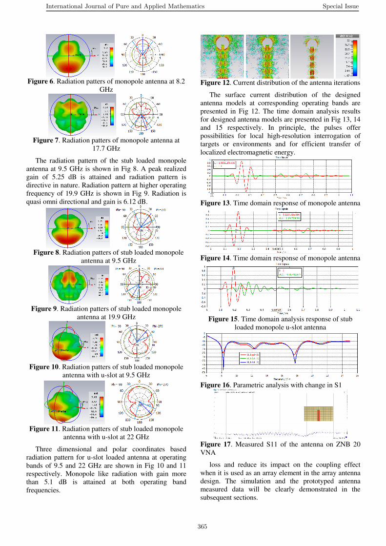
Figure 6. Radiation patters of monopole antenna at 8.2
GHz
Figure 7. Radiation patters of monopole antenna at
17.7 GHz
The radiation pattern of the stub loaded monopole
antenna at 9.5 GHz is shown in Fig 8. A peak realized
gain of 5.25 dB is attained and radiation pattern is
directive in nature. Radiation pattern at higher operating
frequency of 19.9 GHz is shown in Fig 9. Radiation is
quasi omni directional and gain is 6.12 dB.
Figure 8. Radiation patters of stub loaded monopole
antenna at 9.5 GHz
Figure 9. Radiation patters of stub loaded monopole
antenna at 19.9 GHz
Figure 10. Radiation patters of stub loaded monopole
antenna with u-slot at 9.5 GHz
Figure 11. Radiation patters of stub loaded monopole
antenna with u-slot at 22 GHz
Three dimensional and polar coordinates based
radiation pattern for u-slot loaded antenna at operating
bands of 9.5 and 22 GHz are shown in Fig 10 and 11
respectively. Monopole like radiation with gain more
than 5.1 dB is attained at both operating band
frequencies.
Figure 12. Current distribution of the antenna iterations
The surface current distribution of the designed
antenna models at corresponding operating bands are
presented in Fig 12. The time domain analysis results
for designed antenna models are presented in Fig 13, 14
and 15 respectively. In principle, the pulses offer
possibilities for local high-resolution interrogation of
targets or environments and for efficient transfer of
localized electromagnetic energy.
Figure 13. Time domain response of monopole antenna
Figure 14. Time domain response of monopole antenna
Figure 15. Time domain analysis response of stub
loaded monopole u-slot antenna
Figure 16. Parametric analysis with change in S1
Figure 17. Measured S11 of the antenna on ZNB 20
VNA
loss and reduce its impact on the coupling effect
when it is used as an array element in the array antenna
design. The simulation and the prototyped antenna
measured data will be clearly demonstrated in the
subsequent sections.
International Journal of Pure and Applied Mathematics Special Issue
365

4. Conclusion
Defected ground structured monopole antenna
models are proposed for X and Ku band communication
applications in this paper. The designed models of
monopole antenna and stub loaded antenna are
providing excellent bandwidth characteristics in the
wideband and U-slot loaded antenna is showing notch
band characteristics. A bandwidth of 12.5 GHz from
monopole antenna and 16.5 GHz from stub loaded
antenna is attained. Impedance bandwidth of 78% from
monopole antenna and 96% from stub loaded antenna is
also attained with VSWR<2 in the operating band. The
notch band antenna is designed to notch the Ku-band
and passing X and K-bands. The proposed antenna
models are applicable in the satellite communication
systems and capable of transmitting high data rates in
their operating band.
5. Acknowledgement
Authors thankful to department of ECE of K L
University, St. Mary’s and PSCMCE for their
encouragement and DST for the support from grants
ECR/2016/000569 and SR/FST/ETI-316/2012.
References
[1] B T P Madhav, Harish Kaza, Thanneru
Kartheek, Vidyullatha Lakshmi Kaza, Sreeramineni
Prasanth, K S Sanjay Chandra Sikakollu, Maneesh
Thammishetti, Aluvala Srinivas, and K V L Bhavani,
Novel Printed Monopole Trapezoidal Notch Antenna
with S-Band Rejection, J. Theoret. Appl. Information
Tech. ISSN: 1992-8645, 76(1) (2015), 42-49.
[2] P.Lakshmikanth, Kh Takeshore, B T P
Madhav, Printed Log Periodic dipole antenna with
Notched filter at 2.45 GHz Frequency for wireless
communication applications, J. Engg. Applied
Sciences, ISSN: 1816-949X, 10(3), (2015), 40-44,
doi: 10.3923/jeasci.2015.40.44.
[3] D S Ram Kiran, B T P Madhav, Novel compact
asymmetrical fractal aperture Notch band antenna,
Leonardo Electronic Journal of Practices and
Technologies, ISSN 1583-1078, 27(2) (2015), 1-12.
[4] M L S N S Lakshmi, Habibulla Khan and B T
P Madhav, Novel Sequential Rotated 2x2 Array
Notched Circular Patch Antenna, J. Engg. Science
and Tech. Review, ISSN: 1791-2377, 8(4), (2015),
73-77.
[5] M. V. Reddiah Babu, Sarat K. Kotamraju, B. T.
P. Madhav, Compact Serrated Notch Band MIMO
Antenna For UWB Applications, ARPN J. Engg.
Appl. Sciences, ISSN 1819-6608, 11(7) (2016), 4358-
4369.
[6] M Ajay babu, B T P Madhav, D Naga
Vaishnavi, P Radhakrishna, N Bharath, K Madhuri, K
Bhavani Prasad, K Harish, Flared V-Shape Slotted
Monopole Multiband Antenna with Metamaterial
Loading, Int. J. Comm. Ant. Propag. ISSN: 2039-
5086, 5(2), (2015), 93-97.
[7] S S Mohan Reddy, P Mallikarjuna rao, B T P
Madhav, Asymmetric Defected Ground Structured
Monopole Antenna for Wideband Communication
Systems, Int. J. Comm. Ant. Propag. ISSN: 2039-5086,
5(5), (2015), 256-262.
[8] B. T. P. Madhav, Habibulla Khan, Sarat K.
Kotamraju, Circularly Polarized Slotted Aperture
Antenna With Coplanar Waveguide Fed for Broadband
Applications, J. Engg Science and Tech., ISSN: 1823-
4690, 11(2), (2016), 267 – 277.
[9] T V Rama Krishna, B T P Madhav, G Monica,
V Janakiram, S Md Abid Basha, Microstrip Line Fed
Leaky Wave Antenna with Shorting Vias for Wideband
Systems, Int. J. Elec. Comp. Engg. (IJECE), ISSN:
2088-8708, 6(4), (2016), 1725-1731, doi:
10.11591/ijece.v6i4.10699.
[10] P Syam Sundar, Sarat K Kotamraju, B T P
Madhav, Parasitic Strip Loaded Dual Band Notch
Circular Monopole Antenna with Defected Ground
Structure, Int. J. Elec. Comp. Engg (IJECE), ISSN:
2088-8708, 6(4), (2016), 1742-1750, doi:
10.11591/ijece.v6i4.10529.
[11] T. Padmapriya and V. Saminadan, “Distributed
Load Balancing for Multiuser Multi-class Traffic in
MIMO LTE-Advanced Networks”, Research Journal of
Applied Sciences, Engineering and Technology
(RJASET) - Maxwell Scientific Organization , ISSN:
2040-7459; e-ISSN: 2040-7467, vol.12, no.8, pp:813-
822, April 2016.
International Journal of Pure and Applied Mathematics Special Issue
366

367

368