international journal of thermal...
TRANSCRIPT

lable at ScienceDirect
International Journal of Thermal Sciences 49 (2010) 1732e1741
Contents lists avai
International Journal of Thermal Sciences
journal homepage: www.elsevier .com/locate/ i j ts
Experimental and CFD investigation of a lumped parameter thermalmodel of a single-sided, slotted axial flux generator
C.H. Lim a,*, G. Airoldi a, J.R. Bumby a, R.G. Dominy a, G.I. Ingram a,K. Mahkamov a, N.L. Brownb, A. Mebarki b, M. Shanel b
aDurham University School of Engineering and Computing Sciences, South Road, Durham DH1 3LE, UKbCummins Generator Technologies, Barnack Road, Stamford, Lincolnshire PE9 2NB, UK
a r t i c l e i n f o
Article history:Received 20 July 2009Received in revised form30 March 2010Accepted 30 March 2010Available online 6 May 2010
Keywords:Axial flux generatorComputational fluid dynamics (CFDs)Conduction thermal modellingConvection thermal modellingLumped parameter model (LPM)Thermal networkThermal modelling
* Corresponding author. Tel.: þ44 (0) 191 33 42375E-mail address: [email protected] (C.H. Lim).
1290-0729/$ e see front matter � 2010 Elsevier Masdoi:10.1016/j.ijthermalsci.2010.03.018
a b s t r a c t
A two dimensional lumped parameter model (LPM) which provides the steady state solution of temper-atures within axisymmetric single-sided, slotted axial flux generators is presented in this paper. The twodimensional model refers to the heat modelling in the radial and axial directions. The heat flow in thecircumferential direction is neglected. In this modellingmethod, the solid components and the internal airflowdomain of the axial fluxmachine are split into a number of interacting control volumes. Subsequently,each of these control volumes is represented by thermal resistances and capacitances to form a twodimensional axisymmetric LPM thermal circuit. Both conductive and convective heat transfers are takeninto consideration in the LPM thermal circuit by using annular conductive and convective thermal circuitsrespectively. In addition, the thermal circuit is formulated out of purely dimensional information andconstant thermal coefficients. Thus, it can be easily adapted to a range of machine sizes. CFD thermalmodelling and experimental testing are conducted to validate the temperatures predicted from the LPMthermal circuit. It is shown that the LPM thermal circuit is capable of predicting the surface temperatureaccurately and potentially replacing the CFD modelling in the axial flux machine rapid design process.
� 2010 Elsevier Masson SAS. All rights reserved.
1. Introduction
There are several general purpose advanced computational fluiddynamic (CFD) codes commercially available in the market, e.g.ANSYS CFX and FLUENT. These CFD packages use the most modernsolution technology and extremely efficient parallelization algo-rithms to perform 2- and 3-dimensional mass transfer and thermalmodelling of internal and external flow systems. CFD modellingmethods have been used extensively in the past decade, especiallyby electrical machine manufacturers to perform the thermal anal-ysis of electrical machines [1], cooling and air ventilation modelling[2], and the thermal management of AC electrical motors [3].However, sophisticated CFD modelling involves complicated andtime consuming processes, including the geometrical meshing andthe iterative calculation processes. Depending on the applicationand required accuracy, some of the complex models consume up tomonths of simulation time to obtain accurate numerical solutions.This makes it difficult to use advanced CFD techniques for machinerapid design, optimisation and “what-if” analyses.
.
son SAS. All rights reserved.
A feasible alternative to CFDmodelling for the thermal modellingof electrical machines is the application of advanced lumpedparameter modelling (LPM) methods. Instead of solving the heatconduction (Fourier) and convective heat transfer (Newton) equa-tions analytically to simulate the temperature distribution inside thegenerator [4], in the LPM approach described in [5,6], the electricalmachine is split into a number of lumped components (or controlvolumes), which are connected to each other in the calculationscheme through thermal impedances to form a thermal circuit.Several thermal circuits of electrical machines, such as inductionmotors [7], radialflux [8] and stationaryaxialflux generators [9] havebeen proposed. These papers demonstrate that the results of LPMmodelling are in good agreement with experimental data. Similarresearch was conducted by using a commercially available LPMthermal modelling tool [10e12], namely Motor-CAD [13].
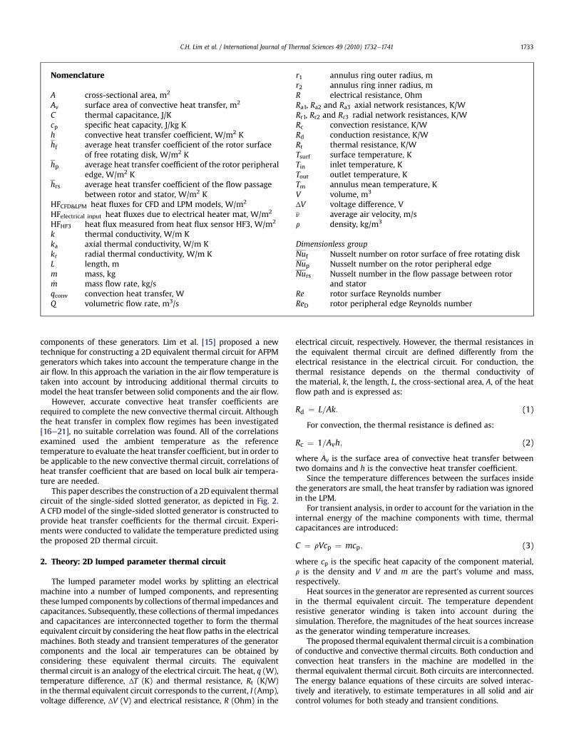
One of the shortcomings of the LPMmethods thatwere employedin previous works [4e12,14] is that the air temperature variations inthe electrical machines were neglected. The air temperature varia-tions are crucial for thermal modelling of electrical machines, espe-cially for axial flux permanent magnet (AFPM) machines, whichtypically have narrow and long flow passages and relatively highvelocities of the cooling air as shown Fig. 1. The variation in thetemperature of the air flow affects the thermal state of the solid
Nomenclature
A cross-sectional area, m2
Av surface area of convective heat transfer, m2
C thermal capacitance, J/Kcp specific heat capacity, J/kg Kh convective heat transfer coefficient, W/m2 Khf average heat transfer coefficient of the rotor surface
of free rotating disk, W/m2 Khp average heat transfer coefficient of the rotor peripheral
edge, W/m2 Khrs average heat transfer coefficient of the flow passage
between rotor and stator, W/m2 KHFCFD&LPM heat fluxes for CFD and LPM models, W/m2
HFelectrical input heat fluxes due to electrical heater mat, W/m2
HFHF3 heat flux measured from heat flux sensor HF3, W/m2
k thermal conductivity, W/m Kka axial thermal conductivity, W/m Kkr radial thermal conductivity, W/m KL length, mm mass, kg_m mass flow rate, kg/sqconv convection heat transfer, WQ volumetric flow rate, m3/s
r1 annulus ring outer radius, mr2 annulus ring inner radius, mR electrical resistance, OhmRa1, Ra2 and Ra3 axial network resistances, K/WRr1, Rr2 and Rr3 radial network resistances, K/WRc convection resistance, K/WRd conduction resistance, K/WRt thermal resistance, K/WTsurf surface temperature, KTin inlet temperature, KTout outlet temperature, KTm annulus mean temperature, KV volume, m3
ΔV voltage difference, Vv average air velocity, m/sr density, kg/m3
Dimensionless groupNuf Nusselt number on rotor surface of free rotating diskNup Nusselt number on the rotor peripheral edgeNurs Nusselt number in the flow passage between rotor
and statorRe rotor surface Reynolds numberReD rotor peripheral edge Reynolds number
C.H. Lim et al. / International Journal of Thermal Sciences 49 (2010) 1732e1741 1733
components of these generators. Lim et al. [15] proposed a newtechnique for constructing a 2D equivalent thermal circuit for AFPMgenerators which takes into account the temperature change in theair flow. In this approach the variation in the air flow temperature istaken into account by introducing additional thermal circuits tomodel the heat transfer between solid components and the air flow.
However, accurate convective heat transfer coefficients arerequired to complete the new convective thermal circuit. Althoughthe heat transfer in complex flow regimes has been investigated[16e21], no suitable correlation was found. All of the correlationsexamined used the ambient temperature as the referencetemperature to evaluate the heat transfer coefficient, but in order tobe applicable to the new convective thermal circuit, correlations ofheat transfer coefficient that are based on local bulk air tempera-ture are needed.
This paper describes the construction of a 2D equivalent thermalcircuit of the single-sided slotted generator, as depicted in Fig. 2.A CFD model of the single-sided slotted generator is constructed toprovide heat transfer coefficients for the thermal circuit. Experi-ments were conducted to validate the temperature predicted usingthe proposed 2D thermal circuit.
2. Theory: 2D lumped parameter thermal circuit
The lumped parameter model works by splitting an electricalmachine into a number of lumped components, and representingthese lumped components by collections of thermal impedances andcapacitances. Subsequently, these collections of thermal impedancesand capacitances are interconnected together to form the thermalequivalent circuit by considering the heat flow paths in the electricalmachines. Both steady and transient temperatures of the generatorcomponents and the local air temperatures can be obtained byconsidering these equivalent thermal circuits. The equivalentthermal circuit is an analogy of the electrical circuit. The heat, q (W),temperature difference, ΔT (K) and thermal resistance, Rt (K/W)in the thermal equivalent circuit corresponds to the current, I (Amp),voltage difference, ΔV (V) and electrical resistance, R (Ohm) in the
electrical circuit, respectively. However, the thermal resistances inthe equivalent thermal circuit are defined differently from theelectrical resistance in the electrical circuit. For conduction, thethermal resistance depends on the thermal conductivity ofthe material, k, the length, L, the cross-sectional area, A, of the heatflow path and is expressed as:
Rd ¼ L=Ak: (1)
For convection, the thermal resistance is defined as:
Rc ¼ 1=Avh; (2)
where Av is the surface area of convective heat transfer betweentwo domains and h is the convective heat transfer coefficient.
Since the temperature differences between the surfaces insidethe generators are small, the heat transfer by radiationwas ignoredin the LPM.
For transient analysis, in order to account for the variation in theinternal energy of the machine components with time, thermalcapacitances are introduced:
C ¼ rVcp ¼ mcp; (3)
where cp is the specific heat capacity of the component material,r is the density and V and m are the part’s volume and mass,respectively.
Heat sources in the generator are represented as current sourcesin the thermal equivalent circuit. The temperature dependentresistive generator winding is taken into account during thesimulation. Therefore, the magnitudes of the heat sources increaseas the generator winding temperature increases.
The proposed thermal equivalent thermal circuit is a combinationof conductive and convective thermal circuits. Both conduction andconvection heat transfers in the machine are modelled in thethermal equivalent thermal circuit. Both circuits are interconnected.The energy balance equations of these circuits are solved interac-tively and iteratively, to estimate temperatures in all solid and aircontrol volumes for both steady and transient conditions.
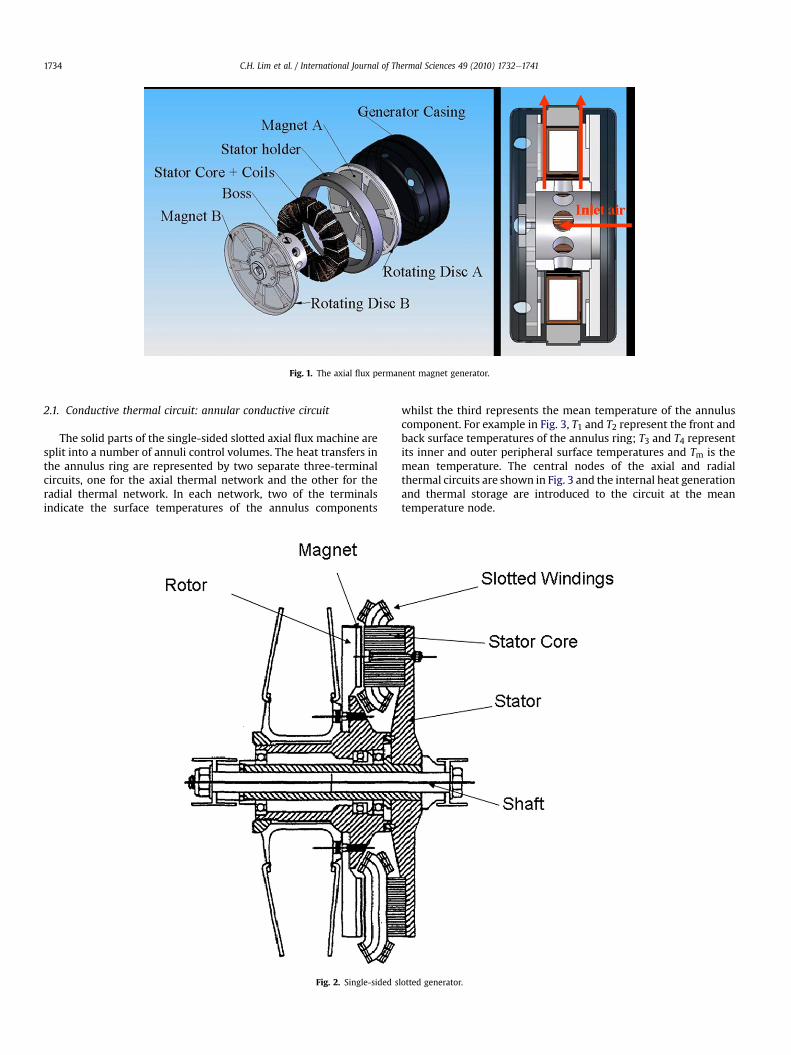
Fig. 1. The axial flux permanent magnet generator.
C.H. Lim et al. / International Journal of Thermal Sciences 49 (2010) 1732e17411734
2.1. Conductive thermal circuit: annular conductive circuit
The solid parts of the single-sided slotted axial flux machine aresplit into a number of annuli control volumes. The heat transfers inthe annulus ring are represented by two separate three-terminalcircuits, one for the axial thermal network and the other for theradial thermal network. In each network, two of the terminalsindicate the surface temperatures of the annulus components
Fig. 2. Single-sided s
whilst the third represents the mean temperature of the annuluscomponent. For example in Fig. 3, T1 and T2 represent the front andback surface temperatures of the annulus ring; T3 and T4 representits inner and outer peripheral surface temperatures and Tm is themean temperature. The central nodes of the axial and radialthermal circuits are shown in Fig. 3 and the internal heat generationand thermal storage are introduced to the circuit at the meantemperature node.
lotted generator.
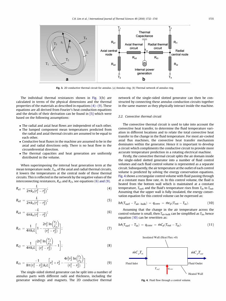
Fig. 3. 2D conductive thermal circuit for annulus. (a) Annulus ring. (b) Thermal network of annulus ring.
inpTCm outpTCm
Tsurf qconv
Heated Wall
Fluid Inlet Fluid Outlet
Insulated Wall (Heat Flux =0)
Fig. 4. Fluid flow through a control volume.
C.H. Lim et al. / International Journal of Thermal Sciences 49 (2010) 1732e1741 1735
The individual thermal resistances shown in Fig. 3(b) arecalculated in terms of the physical dimensions and the thermalproperties of the materials as described in equations (4)e(9). Theseequations are all derived from Fourier’s heat conduction equationsand the details of their derivation can be found in [5] which werebased on the following assumptions:
� The radial and axial heat flows are independent of each other.� The lumped component mean temperatures predicted fromthe radial and axial thermal circuits are assumed to be equal toeach other.
� Conductive heat fluxes in the machine are assumed to be in theaxial and radial directions only. There is no heat flow in thecircumferential direction.
� The thermal capacities and heat generation are uniformlydistributed in the volume.
When superimposing the internal heat generation term at themean temperature node, Tm, of the axial and radial thermal circuits,it lowers the temperatures at the central node of those thermalcircuits. This is reflected in the network by the negative values of theinterconnecting resistances, Ra3 and Rr3, see equations (6) and (9).
Ra1 ¼ L2pka
�r21 � r22
�; (4)
Ra2 ¼ L2pka
�r21 � r22
�; (5)
Ra3 ¼ �L6pka
�r21 � r22
�; (6)
Rr1 ¼ 14pkrL
"1�
2r22 ln�r1r2
��r21 � r22
�#; (7)
Rr2 ¼ 14pkrL
"2r21 ln�r1r2
��r21 � r22
� � 1
#; (8)
Rr3 ¼ �18p
�r21 � r22
�krL
"r21 þ r22 �
4r21r22 ln
�r1r2
��r21 � r22
�#: (9)
The single-sided slotted generator can be split into a number ofannulus parts with different radii and thickness, including thegenerator windings and magnets. The 2D conductive thermal
network of the single-sided slotted generator can then be con-structed by connecting these annulus conduction circuits togetherin the same manner as they physically interact inside the machine.
2.2. Convective thermal circuit
The convective thermal circuit is used to take into account theconvective heat transfer, to determine the fluid temperature vari-ation in different locations and to relate the total convective heattransfer to the change in the fluid temperature. For most air-cooledaxial flux machines, the convective heat transfer mechanismdominates within the generator. Hence it is important to developa circuit which compliments the conductive circuit to provide moreaccurate temperature prediction in a rotating electrical machine.
Firstly, the convective thermal circuit splits the air domain insidethe single-sided slotted generator into a number of fluid controlvolumes and each fluid control volume is represented as a separatecircuit. Subsequently, the air temperature at the outlet of each controlvolume is predicted by solving the energy conservation equations.Fig. 4 shows a rectangular control volumewith fluid passing throughat a constant mass flow rate, _m. In this control volume, the fluid isheated from the bottom wall which is maintained at a constanttemperature, Tsurf, and the fluid’s temperature rises from Tin to Tout.Assuming that the upper wall is fully insulated, the energy conser-vation equation for this control volume can be expressed as:
hAðTsurf � Tair�bulkÞ ¼ qconv ¼ _mcpðTout � TinÞ: (10)
Assuming that the change in the air temperature across thecontrol volume is small, then Tair-bulk can be simplified as Tin, henceequation (10) can be rewritten as:
hAðTsurf � TinÞ ¼ qconv ¼ _mCpðTout � TinÞ: (11)

C.H. Lim et al. / International Journal of Thermal Sciences 49 (2010) 1732e17411736
In order to calculate Tout from equation (11), it is necessary tofind the heat transferred from the wall, qconv. On the other hand,qconv can be calculated by the Newton convection heat transferequation, as shown in the first two terms of equation (11). Byrearranging the Newton convection heat transfer equation, qconvcan be represented by equation (12),
qconv ¼ ðTsurf � TinÞ1hA
: (12)
Furthermore, equation (12) can be represented by an electricalcircuit as shown in Fig. 5, where qconv is analogous to the current;(Tsurf � Tin) is analogous to the voltage difference and 1/hA isanalogous to electrical resistance.
By connecting the Tsurf node to the solid temperature sources, orto the temperature nodes from other conduction thermal circuitsdescribed in Section 2.1, qconv can be calculated by measuring theheat across the heat meter in the convective thermal circuit shownin Fig. 5.
To obtain the temperature at the outlet of the control volume,Tout, equation (11) is rearranged so that the fluid temperature at theoutlet, Tout, is written in terms of qconv and the known boundaryconditions at the inlet, such as Tin and cp. With qconv calculated fromthe convective thermal circuit in Fig. 5, Tout can be predicted as:
Tout ¼ qconv_mcp
þ Tin: (13)
Once computed, the predicted Tout of the air control volume ispassed to the neighboring air control volume. Similarly, the outlettemperature in the second air control volume is predicted using itscorresponding equivalent convective thermal circuit and equation(13). By using this process, all the temperatures from the systeminlet to the last air control volume at the outlet are determined. Thecalculation is run iteratively until the solution reaches convergence.
The accuracy of the convective equivalent thermal circuitdepends on the assumption made to derive equation (11), i.e. thatthe change in temperature between the inlet and outlet is small. Toimprove the accuracy of the convective thermal circuit, it isnecessary to discretise the air domain into finer control volumes toreduce the temperature change across it. Model discretisation
Fig. 5. Convective thermal circuit for control volume.
studies of lumped parameter models are described in reference[15], and the authors conclude that splitting their model into threecontrol volumes in the radial direction in their axial flux machine issufficient to provide good results. Therefore, the air domain in theaxial fluxmachine is discretised into three control volumes in radialdirection.
2.3. The construction of the single-sided slotted generator2D lumped parameter thermal circuit
The LPM thermal circuit of the simplified single-sided slottedgenerator is constructed as shown in Fig. 6. The simplified single-sided slotted generator consists of a rotor disk (on the left hand side)and a stator disk (on the right hand side); each of them is split in tofour and three annular control volumes respectively. The annularcontrol volumes are represented by the annular conductive circuitmentioned and they are connected at the axial and radial temper-ature terminals in the same way that they are physically connectedin the real machine. The thermal resistances of the conductivethermal circuit are calculated by using equations (4)e(9), based onthe geometry and material properties of each annular controlvolume.
Single and double-sided slotted axial flux machines are oftendesigned with very thin magnets protruding from the rotor disksurface. Typically, the magnet grooves range between 2 and 4 mm.Furthermore, some commercial axial flux machine designs havemagnets flush with the rotor disk for magnetic flux optimisation.Hence, in this analysis, the magnets on the rotor disk are omitted.The air domain inside the generator is split into four controlvolumes as shown in Fig. 6(a). The convective thermal circuit isconnected to the conduction circuit to allow heat transfer from theair to the solid or vice versa. The temperature dependent Jouleheating loss in the winding on the slotted stator is modelled by anindependent transient heat source in the LPM thermal circuit.
The accuracy of the temperature prediction of the LPM is closelyrelated to the convective heat transfer coefficients used in themodel. Nevertheless, accurately determining convection heattransfer coefficients is difficult due to the complexity of the flowregimes and it involves extensive theoretical and experimentalexplorations. In this LPM model, the convective heat transfers areevaluated by a number of existing correlations [22] based on theflow characteristic in the axial flux machine.
2.3.1. Free rotating dicsThe average heat transfer coefficient on the left hand side of the
rotor surface is developed using the formula developed fora combination of laminar and turbulent flow of a free rotating plate[23], which is,
hf ¼ krNuf ; (14)
where
Nuf ¼ 0:015Re4=5u � 100�rcr
�2: (15)
In equation (15)
rc ¼�2:5� 105
v
u
�12; (16)
where rc is the radius at which the transition occurs from laminarflow to turbulent flow, m; v is the fluid kinematic viscosity, m2/s;u is the rotational speed, rad/s; r is the disk outer radius, m; Reu isthe rotational Reynolds number, which is defined as Reu ¼ ur2=v; kis the air thermal conductivity, W/m K.

Fig. 6. (a) Simplified single-sided slotted axial flux generator and (b) the corresponding lumped parameter thermal circuit.
C.H. Lim et al. / International Journal of Thermal Sciences 49 (2010) 1732e1741 1737
Considering the single slotted axial flux generator described inFig. 6(a), with an outer radius, rc, of 0.15 m, rotational speed, u, of1495 rpm (or 156.5 rad/s) and air kinematic viscosity and thermalconductivity of 16.97 � 10�6 m2/s and 0.0271 W/m K respectively,the convection heat transfer coefficient on the rotor side surface,hf , calculated from equations (14)e(16) is 26.83 W/m2 K.
2.3.2. Rotor peripheral edgeThe heat transfer coefficients for the radial periphery of the
rotor disk are similar to the rotating cylinder in air. Hence theaverage heat transfer coefficient is given as [22]:
hp ¼ kDNup; (17)
where
Nup ¼ 0:133Re2=3D Pr1=3: (18)
In equation (18)
ReD ¼ uD2
v; (19)
whereD is the rotor disk diameter, m, Pr is the air Prandtl’s Number.Subsequently, when D ¼ 0.30 m, Pr ¼ 0.711 and u ¼ 156.5 rad/s,
the average convection heat transfer coefficient at the peripheraledge of the rotor disk, hp, is found to be 94.7 W/m2 K.
2.3.3. Flow passage between the rotor and the statorOwen [21] provided an approximation solution for the flow
between a rotating and a stationary disk, which relates the stator-side average Nusselt number to the volumetric flow rate, Q (m3/s)by the following equation:
hrs ¼ krNurs; (20)
where
Nurs ¼ 0:333Qpyr
: (21)
Since no mass flow correlation has been developed for the singleslotted axial flux generator, the mass flow was determined fromthe experiments and found to be equal to 3.61 g/s. This is used tocalculate an average stator-side heat transfer coefficient, hrsof22.63W/m2Kwas obtained fromequations (20) and (21). Also,Wang[22] suggests that the convection heat transfer coefficient on therotating disk can be assumed to be the same as on the stator-side.
In this semi-empirical lumped parameter thermal circuit,experimental results are required to evaluate the mass flow ratesand heat transfer coefficients in the electrical machines. In thefuture, sophisticated parametric variation studies of convectiveheat transfer coefficient and mass flow rate will be performed todevelop the empirical correlations that relate the heat transfercoefficient and mass flow rate with different flow conditions andgeometrical parameters. Hence, the LPM will be able to provideaccurate temperature values inside the AFPM generators inde-pendently from the numerical models or CFD model.
3. The single-sided slotted generator CFD model
An axisymmetric CFD model of the simplified single-sidedslotted generator was constructed and simulated in FLUENT 6.3.26package. In this model, only the heat and air flows in the axial andradial directions are simulated. The heat flux and air flow rate incircumferential direction is assumed to be constant. The CFDmodelmesh grid shown in Fig. 7(b) consists of 40,000 nodes. The addi-tional air volumes at the inlet and outlet are modelled to eliminatethe boundary interference in the CFD model. On a modestly pow-ered desktop computer (1.773 GHz Core Duo Intel processor, 1 GBRAMmachine), the meshing process and iterative calculation of theCFDmodelling took up to 9 h of computational time. The input dataand the boundary conditions applied in the CFD model are asfollows:
� 0.3 m outer diameter and 0.01 m thick rotor disk.� 0.3 m outer diameter, 0.07 m inner diameter and 0.008 m thickstator disk.
� 3 mm rotorestator clearance.� 15 �C ambient temperature.� Boundary layers are used in the near wall region.
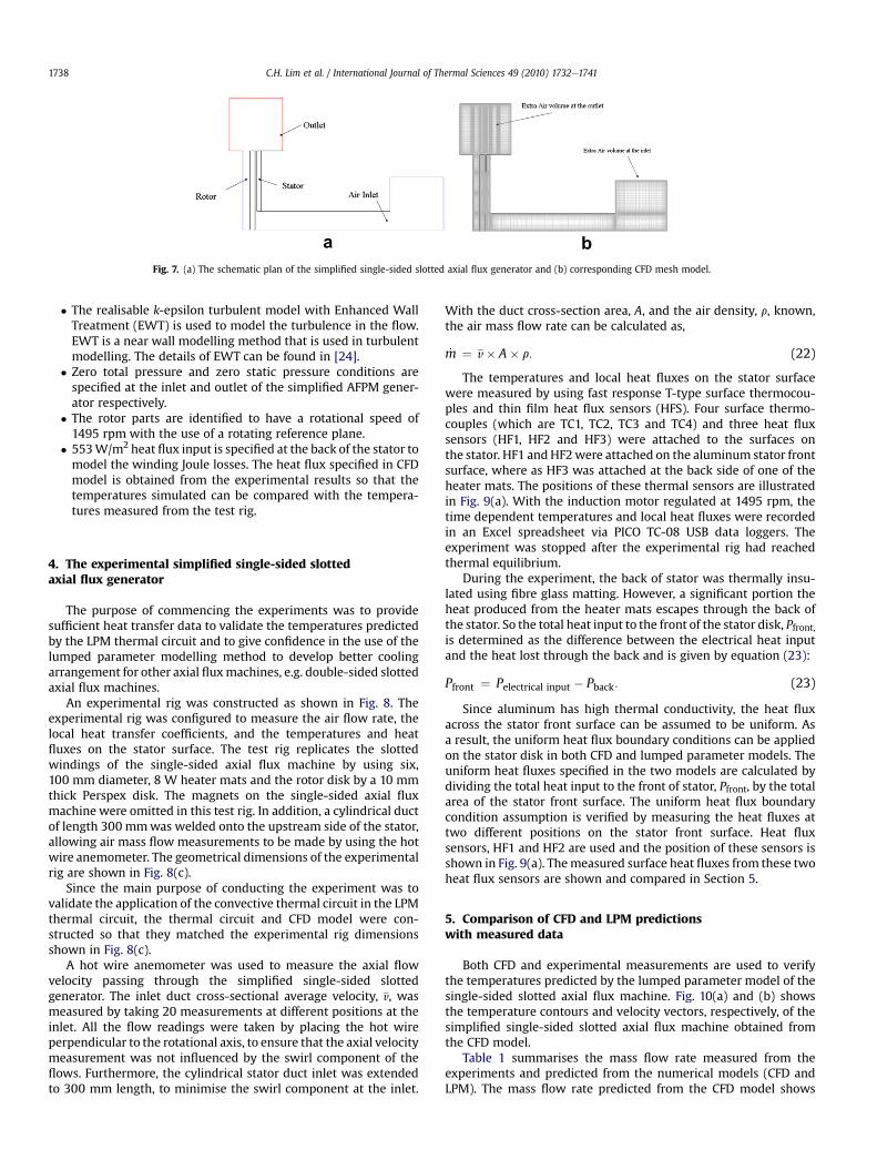
Fig. 7. (a) The schematic plan of the simplified single-sided slotted axial flux generator and (b) corresponding CFD mesh model.
C.H. Lim et al. / International Journal of Thermal Sciences 49 (2010) 1732e17411738
� The realisable k-epsilon turbulent model with Enhanced WallTreatment (EWT) is used to model the turbulence in the flow.EWT is a near wall modelling method that is used in turbulentmodelling. The details of EWT can be found in [24].
� Zero total pressure and zero static pressure conditions arespecified at the inlet and outlet of the simplified AFPM gener-ator respectively.
� The rotor parts are identified to have a rotational speed of1495 rpm with the use of a rotating reference plane.
� 553W/m2 heat flux input is specified at the back of the stator tomodel the winding Joule losses. The heat flux specified in CFDmodel is obtained from the experimental results so that thetemperatures simulated can be compared with the tempera-tures measured from the test rig.
4. The experimental simplified single-sided slottedaxial flux generator
The purpose of commencing the experiments was to providesufficient heat transfer data to validate the temperatures predictedby the LPM thermal circuit and to give confidence in the use of thelumped parameter modelling method to develop better coolingarrangement for other axial fluxmachines, e.g. double-sided slottedaxial flux machines.
An experimental rig was constructed as shown in Fig. 8. Theexperimental rig was configured to measure the air flow rate, thelocal heat transfer coefficients, and the temperatures and heatfluxes on the stator surface. The test rig replicates the slottedwindings of the single-sided axial flux machine by using six,100 mm diameter, 8 W heater mats and the rotor disk by a 10 mmthick Perspex disk. The magnets on the single-sided axial fluxmachine were omitted in this test rig. In addition, a cylindrical ductof length 300 mmwas welded onto the upstream side of the stator,allowing air mass flow measurements to be made by using the hotwire anemometer. The geometrical dimensions of the experimentalrig are shown in Fig. 8(c).
Since the main purpose of conducting the experiment was tovalidate the application of the convective thermal circuit in the LPMthermal circuit, the thermal circuit and CFD model were con-structed so that they matched the experimental rig dimensionsshown in Fig. 8(c).
A hot wire anemometer was used to measure the axial flowvelocity passing through the simplified single-sided slottedgenerator. The inlet duct cross-sectional average velocity, v, wasmeasured by taking 20 measurements at different positions at theinlet. All the flow readings were taken by placing the hot wireperpendicular to the rotational axis, to ensure that the axial velocitymeasurement was not influenced by the swirl component of theflows. Furthermore, the cylindrical stator duct inlet was extendedto 300 mm length, to minimise the swirl component at the inlet.
With the duct cross-section area, A, and the air density, r, known,the air mass flow rate can be calculated as,
_m ¼ v� A� r: (22)
The temperatures and local heat fluxes on the stator surfacewere measured by using fast response T-type surface thermocou-ples and thin film heat flux sensors (HFS). Four surface thermo-couples (which are TC1, TC2, TC3 and TC4) and three heat fluxsensors (HF1, HF2 and HF3) were attached to the surfaces onthe stator. HF1 andHF2were attached on the aluminum stator frontsurface, where as HF3 was attached at the back side of one of theheater mats. The positions of these thermal sensors are illustratedin Fig. 9(a). With the induction motor regulated at 1495 rpm, thetime dependent temperatures and local heat fluxes were recordedin an Excel spreadsheet via PICO TC-08 USB data loggers. Theexperiment was stopped after the experimental rig had reachedthermal equilibrium.
During the experiment, the back of stator was thermally insu-lated using fibre glass matting. However, a significant portion theheat produced from the heater mats escapes through the back ofthe stator. So the total heat input to the front of the stator disk, Pfront,is determined as the difference between the electrical heat inputand the heat lost through the back and is given by equation (23):
Pfront ¼ Pelectrical input � Pback: (23)
Since aluminum has high thermal conductivity, the heat fluxacross the stator front surface can be assumed to be uniform. Asa result, the uniform heat flux boundary conditions can be appliedon the stator disk in both CFD and lumped parameter models. Theuniform heat fluxes specified in the two models are calculated bydividing the total heat input to the front of stator, Pfront, by the totalarea of the stator front surface. The uniform heat flux boundarycondition assumption is verified by measuring the heat fluxes attwo different positions on the stator front surface. Heat fluxsensors, HF1 and HF2 are used and the position of these sensors isshown in Fig. 9(a). Themeasured surface heat fluxes from these twoheat flux sensors are shown and compared in Section 5.
5. Comparison of CFD and LPM predictionswith measured data
Both CFD and experimental measurements are used to verifythe temperatures predicted by the lumped parameter model of thesingle-sided slotted axial flux machine. Fig. 10(a) and (b) showsthe temperature contours and velocity vectors, respectively, of thesimplified single-sided slotted axial flux machine obtained fromthe CFD model.
Table 1 summarises the mass flow rate measured from theexperiments and predicted from the numerical models (CFD andLPM). The mass flow rate predicted from the CFD model shows

Fig. 8. The schematic (a), snapshot (b) and geometrical dimensions of the simplified experimental rig.
C.H. Lim et al. / International Journal of Thermal Sciences 49 (2010) 1732e1741 1739
reasonable agreement with the experimental result, being about11% higher than the mass flow rate measured by the hot wireanemometer, see Table 1.
Fig. 11 shows the measured and predicted temperature at fourdifferent radii along the stator surface from the LPM thermal
Fig. 9. Thermocouples and heat flux sensors position
circuits, CFD model and experimental rig respectively. It can beobserved that the temperatures measured (from the experiments)and predicted (from the CFD models) are low as compared to thewinding temperatures in commercial electrical machines. Normalcommercial electrical machines usually operate at stator surface
ing on the stator front (a) and back (b) surface.

Fig. 10. Temperature contour and velocity vectors plot of the single-sided slotted axial machine.
C.H. Lim et al. / International Journal of Thermal Sciences 49 (2010) 1732e17411740
temperatures of 80e120 �C, but the surface temperature measuredor predicted from the experiments and CFD model are of the orderof 30e35 �C.
This is because the power of the heater mats used in theexperiment is low. The rated power of each of the heat mat is 8 Wand six heater mats were used in total. Hence, the total heat input is48 W. Compared with the winding losses of commercial electricalmachines, which range in between 90 and 200 W (for 1.5 kW axialflux machines), the temperatures measured from the experimentsand predicted from the CFD are correspondingly low.
Table 2 shows the heat fluxes measured from the heat fluxsensors attached on the front and back sides of the stator disk. Theresults show that the local heat fluxes measured on the statorsurface are similar. Therefore, a uniform heat flux boundarycondition on the stator front surface can be applied with confidencein the CFD and lumped parameter models for the thermal model-ling of the test rig.
By specifying the convection heat transfer coefficients derivedby the correlations suggested from [21,22] in the LPM model, thetemperatures predicted show a big discrepancy with the resultsobtained from the measurements. The highest absolute discrep-ancy occurs on the stator disk at position TC4 (see Fig. 11), which is20.6% (5.5 �C difference in temperature rise). This confirms that theconvective heat transfer coefficients derived from the correlationsare not sufficient to providing an acceptable temperature approx-imation for the LPMmodel. Hence, to improve the LPM predictions,the existing correlations [21,22] were replaced by local convectionheat transfer coefficients extracted from the CFDmodel. These localconvection heat transfer coefficients are evaluated based on thelocal bulk working fluid (or air) temperatures. Like the LPM model,theworking fluid in the CFDmodel is split into four control volumesas shown in Fig. 6(a). The local bulk air temperatures used for theevaluation of the CFD local convection heat transfer coefficients arecalculated by taking the volumetric average air temperature forthese fluid control volumes. With the new local heat transfercoefficients obtained from CFD input to the 2D LPM, the absolute
Table 1Mass flow rates comparison.
Experiments CFD model
Mass flow rate (g/s) 3.61 4.03
discrepancies of the temperature predictions have reduced signif-icantly as shown in Fig. 11. For example, the absolute discrepancy atTC4 has halved to 10.4% (3 �C difference in temperature rise).
The discrepancies between the two LPMs are due solely to theheat transfer coefficients used in the circuits and they demonstratethat LPMs are very sensitive to convective resistances as opposed toconductive resistances. For most air-cooled axial flux machines, themagnitude of the convective resistance is about two orders ofmagnitude above the conductive resistance. For example theconvective resistance at T4 is 3.35 K/W while the radial conductiveresistance at T4 position is 0.022 K/W. This highlights the necessityof developing a more sophisticated parametric variation study ofconvective heat transfer coefficients and mass flow rates for axialflux machines to complete the LPM model.
Unlike the CFD modelling technique, the determination of thelocal heat transfer coefficients experimentally is difficult, because itis almost impossible to determine local air bulk temperatureaccurately by using thermocouples in the stator-rotor gap. There-fore, only global heat transfer coefficients are measured from the
Fig. 11. The temperatures measured and predicted from experimental rig andnumerical models (CFD and LPM) respectively.
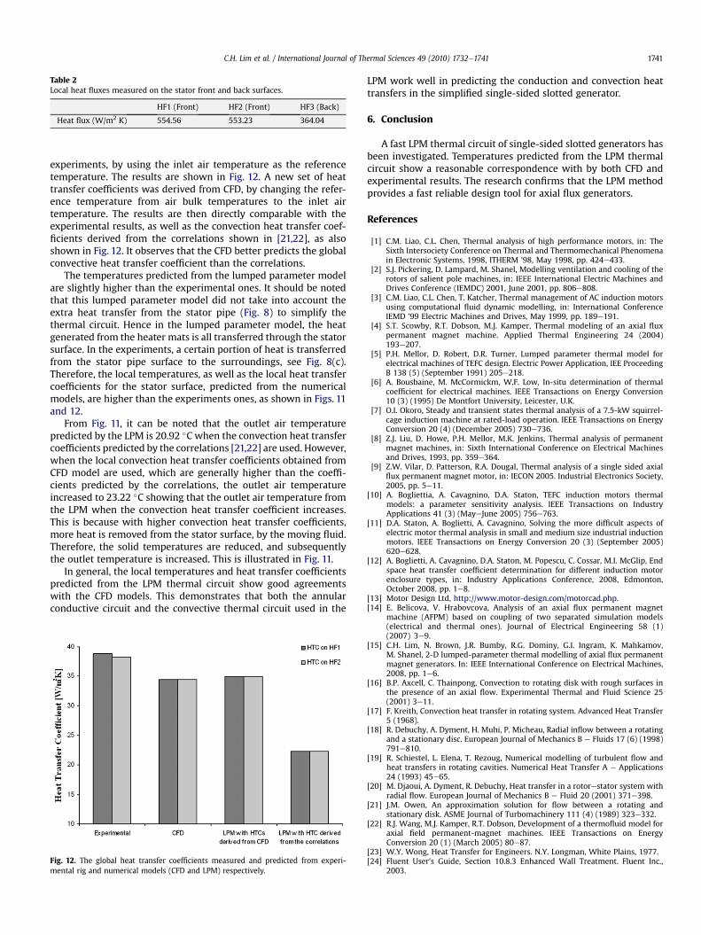
Table 2Local heat fluxes measured on the stator front and back surfaces.
HF1 (Front) HF2 (Front) HF3 (Back)
Heat flux (W/m2 K) 554.56 553.23 364.04
C.H. Lim et al. / International Journal of Thermal Sciences 49 (2010) 1732e1741 1741
experiments, by using the inlet air temperature as the referencetemperature. The results are shown in Fig. 12. A new set of heattransfer coefficients was derived from CFD, by changing the refer-ence temperature from air bulk temperatures to the inlet airtemperature. The results are then directly comparable with theexperimental results, as well as the convection heat transfer coef-ficients derived from the correlations shown in [21,22], as alsoshown in Fig. 12. It observes that the CFD better predicts the globalconvective heat transfer coefficient than the correlations.
The temperatures predicted from the lumped parameter modelare slightly higher than the experimental ones. It should be notedthat this lumped parameter model did not take into account theextra heat transfer from the stator pipe (Fig. 8) to simplify thethermal circuit. Hence in the lumped parameter model, the heatgenerated from the heater mats is all transferred through the statorsurface. In the experiments, a certain portion of heat is transferredfrom the stator pipe surface to the surroundings, see Fig. 8(c).Therefore, the local temperatures, as well as the local heat transfercoefficients for the stator surface, predicted from the numericalmodels, are higher than the experiments ones, as shown in Figs. 11and 12.
From Fig. 11, it can be noted that the outlet air temperaturepredicted by the LPM is 20.92 �C when the convection heat transfercoefficients predicted by the correlations [21,22] are used. However,when the local convection heat transfer coefficients obtained fromCFD model are used, which are generally higher than the coeffi-cients predicted by the correlations, the outlet air temperatureincreased to 23.22 �C showing that the outlet air temperature fromthe LPM when the convection heat transfer coefficient increases.This is because with higher convection heat transfer coefficients,more heat is removed from the stator surface, by the moving fluid.Therefore, the solid temperatures are reduced, and subsequentlythe outlet temperature is increased. This is illustrated in Fig. 11.
In general, the local temperatures and heat transfer coefficientspredicted from the LPM thermal circuit show good agreementswith the CFD models. This demonstrates that both the annularconductive circuit and the convective thermal circuit used in the
Fig. 12. The global heat transfer coefficients measured and predicted from experi-mental rig and numerical models (CFD and LPM) respectively.
LPM work well in predicting the conduction and convection heattransfers in the simplified single-sided slotted generator.
6. Conclusion
A fast LPM thermal circuit of single-sided slotted generators hasbeen investigated. Temperatures predicted from the LPM thermalcircuit show a reasonable correspondence with by both CFD andexperimental results. The research confirms that the LPM methodprovides a fast reliable design tool for axial flux generators.
References
[1] C.M. Liao, C.L. Chen, Thermal analysis of high performance motors, in: TheSixth Intersociety Conference on Thermal and Thermomechanical Phenomenain Electronic Systems, 1998, ITHERM ’98, May 1998, pp. 424e433.
[2] S.J. Pickering, D. Lampard, M. Shanel, Modelling ventilation and cooling of therotors of salient pole machines, in: IEEE International Electric Machines andDrives Conference (IEMDC) 2001, June 2001, pp. 806e808.
[3] C.M. Liao, C.L. Chen, T. Katcher, Thermal management of AC induction motorsusing computational fluid dynamic modelling, in: International ConferenceIEMD ’99 Electric Machines and Drives, May 1999, pp. 189e191.
[4] S.T. Scowby, R.T. Dobson, M.J. Kamper, Thermal modeling of an axial fluxpermanent magnet machine. Applied Thermal Engineering 24 (2004)193e207.
[5] P.H. Mellor, D. Robert, D.R. Turner, Lumped parameter thermal model forelectrical machines of TEFC design. Electric Power Application, IEE ProceedingB 138 (5) (September 1991) 205e218.
[6] A. Bousbaine, M. McCormickm, W.F. Low, In-situ determination of thermalcoefficient for electrical machines. IEEE Transactions on Energy Conversion10 (3) (1995) De Montfort University, Leicester, U.K.
[7] O.I. Okoro, Steady and transient states thermal analysis of a 7.5-kW squirrel-cage induction machine at rated-load operation. IEEE Transactions on EnergyConversion 20 (4) (December 2005) 730e736.
[8] Z.J. Liu, D. Howe, P.H. Mellor, M.K. Jenkins, Thermal analysis of permanentmagnet machines, in: Sixth International Conference on Electrical Machinesand Drives, 1993, pp. 359e364.
[9] Z.W. Vilar, D. Patterson, R.A. Dougal, Thermal analysis of a single sided axialflux permanent magnet motor, in: IECON 2005. Industrial Electronics Society,2005, pp. 5e11.
[10] A. Bogliettia, A. Cavagnino, D.A. Staton, TEFC induction motors thermalmodels: a parameter sensitivity analysis. IEEE Transactions on IndustryApplications 41 (3) (MayeJune 2005) 756e763.
[11] D.A. Staton, A. Boglietti, A. Cavagnino, Solving the more difficult aspects ofelectric motor thermal analysis in small and medium size industrial inductionmotors. IEEE Transactions on Energy Conversion 20 (3) (September 2005)620e628.
[12] A. Boglietti, A. Cavagnino, D.A. Staton, M. Popescu, C. Cossar, M.I. McGlip, Endspace heat transfer coefficient determination for different induction motorenclosure types, in: Industry Applications Conference, 2008, Edmonton,October 2008, pp. 1e8.
[13] Motor Design Ltd, http://www.motor-design.com/motorcad.php.[14] E. Belicova, V. Hrabovcova, Analysis of an axial flux permanent magnet
machine (AFPM) based on coupling of two separated simulation models(electrical and thermal ones). Journal of Electrical Engineering 58 (1)(2007) 3e9.
[15] C.H. Lim, N. Brown, J.R. Bumby, R.G. Dominy, G.I. Ingram, K. Mahkamov,M. Shanel, 2-D lumped-parameter thermal modelling of axial flux permanentmagnet generators. In: IEEE International Conference on Electrical Machines,2008, pp. 1e6.
[16] B.P. Axcell, C. Thainpong, Convection to rotating disk with rough surfaces inthe presence of an axial flow. Experimental Thermal and Fluid Science 25(2001) 3e11.
[17] F. Kreith, Convection heat transfer in rotating system. Advanced Heat Transfer5 (1968).
[18] R. Debuchy, A. Dyment, H. Muhi, P. Micheau, Radial inflow between a rotatingand a stationary disc. European Journal of Mechanics B e Fluids 17 (6) (1998)791e810.
[19] R. Schiestel, L. Elena, T. Rezoug, Numerical modelling of turbulent flow andheat transfers in rotating cavities. Numerical Heat Transfer A e Applications24 (1993) 45e65.
[20] M. Djaoui, A. Dyment, R. Debuchy, Heat transfer in a rotorestator system withradial flow. European Journal of Mechanics B e Fluid 20 (2001) 371e398.
[21] J.M. Owen, An approximation solution for flow between a rotating andstationary disk. ASME Journal of Turbomachinery 111 (4) (1989) 323e332.
[22] R.J. Wang, M.J. Kamper, R.T. Dobson, Development of a thermofluid model foraxial field permanent-magnet machines. IEEE Transactions on EnergyConversion 20 (1) (March 2005) 80e87.
[23] W.Y. Wong, Heat Transfer for Engineers. N.Y. Longman, White Plains, 1977.[24] Fluent User’s Guide, Section 10.8.3 Enhanced Wall Treatment. Fluent Inc.,
2003.