international planetary probe workshop 6 selection and
TRANSCRIPT

International Planetary Probe Workshop 6
Selection and Certification of TPS: Selection and Certification of TPS: Constraints and Considerations Constraints and Considerations for for Venus MissionsVenus Missions
6th International Planetary Probe Workshop (IPPW6)Atlanta, GA
June 23-27, 2008
by
E. Venkatapathy, B. Laub, G. J. HartmanJ. O. Arnold, M. J. Wright and G.A. Allen
NASA Ames Research CenterMoffett Field, CA 94035
Sponsored by the NASA In-Space Propulsion Program

International Planetary Probe Workshop 6
26-29 June 2008 26th International Planetary Probe Workshop
Introduction, Challenge and OutlineIntroduction, Challenge and Outline
TPS: A mission critical, enabling technology for entry probesand orbital insertion via aerocapture
Challenge:– How can TPS technology be affordably developed and
heat shield be certified for flight despite the fact that wecannot “test as you fly and fly as you test”.
– Focus is Venus What considerations define TPS selection for missions? The challenges for TPS development - “Testing and Design
Analysis”
Presentation outline– Mission “pull” for Venus and potential mission architectures– Current arc jet test capabilities– Filling testing gaps: LHMEL, Solar Tower and DAF (foreign?)– Piece-wise certification– Candidate TPS (low and mid-density ablators and carbon phenolic)– Summary of development/certification for Venus missions

International Planetary Probe Workshop 6
26-29 June 2008 36th International Planetary Probe Workshop
Mission Pull - VenusMission Pull - VenusReference - 2002 NRC Decadal PlanningReference - 2002 NRC Decadal Planning
Atmospheric measurements– Composition including trace species and light
stable isotopes– Accurate determination of noble-gas isotopic
abundance Descent, surface and ascent meteorological data Near IR Descent Images from 10 km to the surface Elemental abundances and mineralogy from surface core Texturing of surface materials to understand weathering
These science objectives can only besatisfied with entry probes

International Planetary Probe Workshop 6
26-29 June 2008 46th International Planetary Probe Workshop
Venus Mission Scenarios
Direct EntryDescent to surfacefrom interplanetarytrajectory
AerocaptureOrbit insertion via passagethrough atmosphere frominterplanetary trajectory
Entry from OrbitDescent to surfacefrom planetary orbit
International Planetary Probe Workshop 6
26-29 June 2008 56th International Planetary Probe Workshop
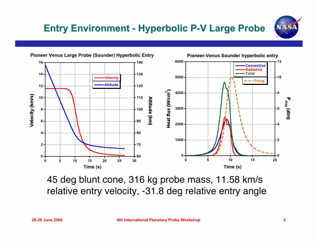
Entry Environment - Hyperbolic P-V Large ProbeEntry Environment - Hyperbolic P-V Large Probe
45 deg blunt cone, 316 kg probe mass, 11.58 km/srelative entry velocity, -31.8 deg relative entry angle

International Planetary Probe Workshop 6
26-29 June 2008 66th International Planetary Probe Workshop
Venus Aerocapture EnvironmentsVenus Aerocapture Environments
70 deg blunt cone, 2.65 m diameter, Entry mass = 1090 kg,Entry velocity = 11.25 km/s, Atmospheric interface = 150 km,Entry FPA = -6.12°, L/D = 0.25, Exit apoapse altitude = 300 kmSource: ISP Systems Study (2004)

International Planetary Probe Workshop 6
26-29 June 2008 76th International Planetary Probe Workshop
Out of Orbit: P-V Large ProbeOut of Orbit: P-V Large Probe
45 deg blunt cone, 316 kg probe mass, 10.20 km/srelative entry velocity, -4 deg relative entry angle

International Planetary Probe Workshop 6
26-29 June 2008 86th International Planetary Probe Workshop
ApplicabilityApplicability of Some Candidate TPS of Some Candidate TPSMaterials Materials For Candidate Venus MissionsFor Candidate Venus Missions
International Planetary Probe Workshop 6
26-29 June 2008 96th International Planetary Probe Workshop
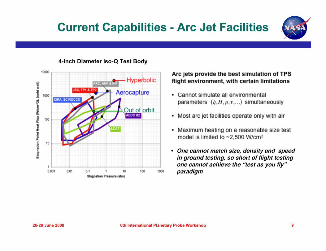
Current Capabilities - Arc Jet FacilitiesCurrent Capabilities - Arc Jet Facilities
4-inch Diameter Iso-Q Test Body
• One cannot match size, density and speedin ground testing, so short of flight testingone cannot achieve the “test as you fly”paradigm
International Planetary Probe Workshop 6
26-29 June 2008 106th International Planetary Probe Workshop
Venus: Testing Gaps/ RequirementsVenus: Testing Gaps/ RequirementsTPS Development FacilitiesTPS Development Facilities
Combined enthalpy, convective heat flux, pressureand shear for hyperbolic entry
Combined radiative and convective heating foraerocapture and hyperbolic entry
– Current arc jet facilities would require externalsources to augment convective heating
Large scale test articles, to reduce size scaling– Requires higher heater power relative to peak heat
flux
Atmosphere is 95% CO2, NOT air…
International Planetary Probe Workshop 6
26-29 June 2008 116th International Planetary Probe Workshop
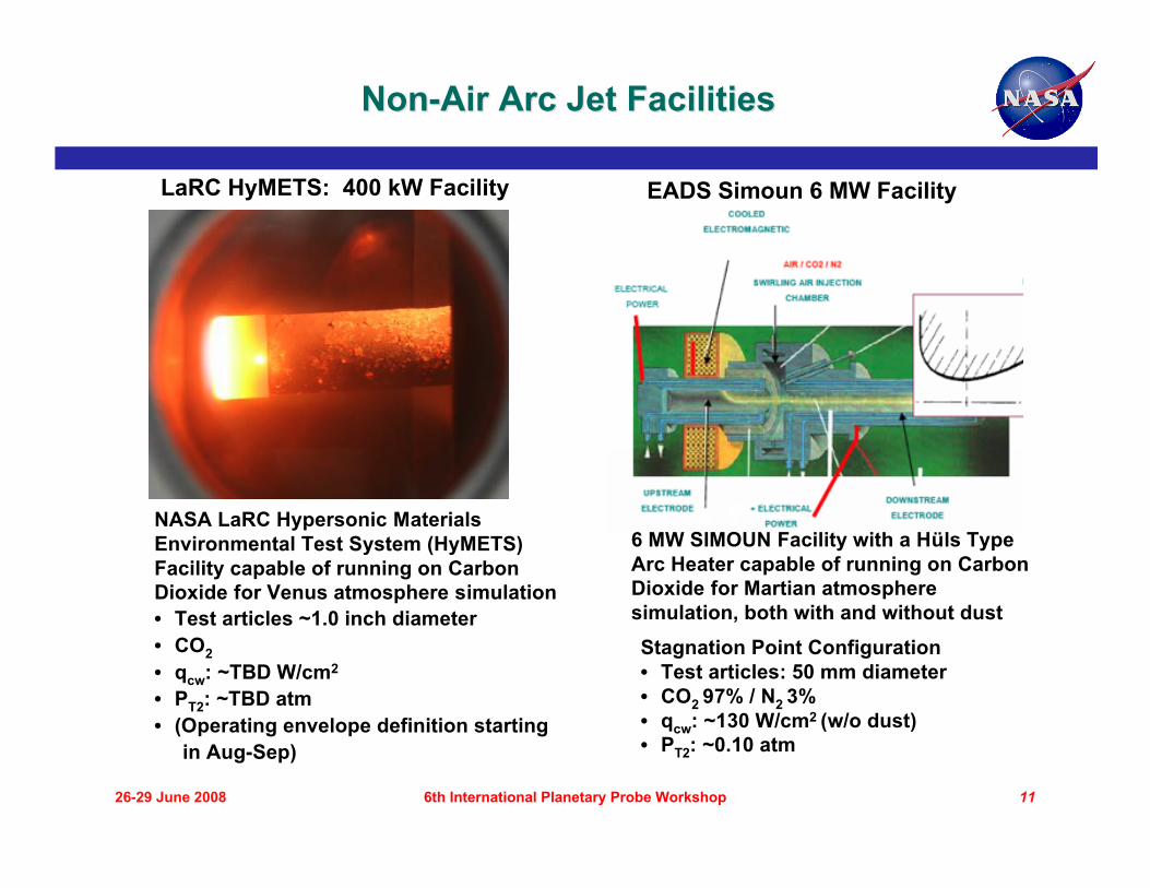
Non-Air Arc Jet FacilitiesNon-Air Arc Jet Facilities
LaRC HyMETS: 400 kW Facility
NASA LaRC Hypersonic MaterialsEnvironmental Test System (HyMETS)Facility capable of running on CarbonDioxide for Venus atmosphere simulation• Test articles ~1.0 inch diameter• CO2• qcw: ~TBD W/cm2
• PT2: ~TBD atm• (Operating envelope definition starting in Aug-Sep)
6 MW SIMOUN Facility with a Hüls TypeArc Heater capable of running on CarbonDioxide for Martian atmospheresimulation, both with and without dust
EADS Simoun 6 MW Facility
Stagnation Point Configuration• Test articles: 50 mm diameter• CO2 97% / N2 3%• qcw: ~130 W/cm2 (w/o dust)• PT2: ~0.10 atm
International Planetary Probe Workshop 6
26-29 June 2008 126th International Planetary Probe Workshop
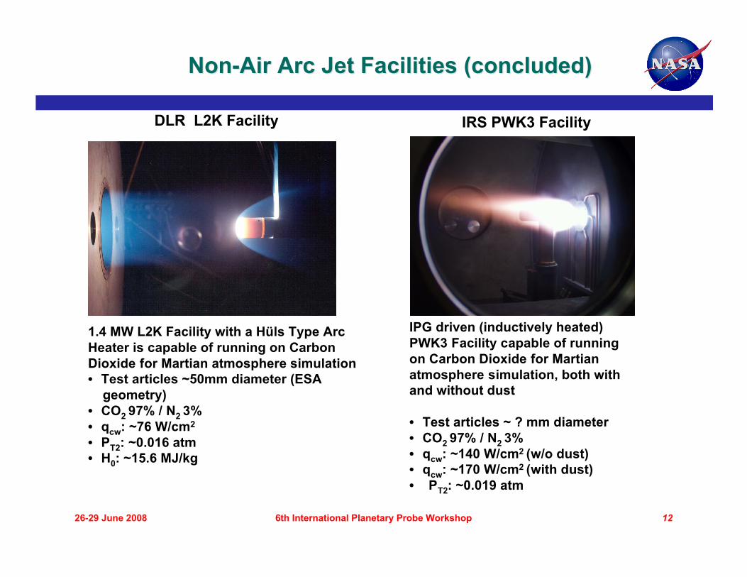
DLR L2K Facility IRS PWK3 Facility
1.4 MW L2K Facility with a Hüls Type ArcHeater is capable of running on CarbonDioxide for Martian atmosphere simulation• Test articles ~50mm diameter (ESA geometry)• CO2 97% / N2 3%• qcw: ~76 W/cm2
• PT2: ~0.016 atm• H0: ~15.6 MJ/kg
IPG driven (inductively heated)PWK3 Facility capable of runningon Carbon Dioxide for Martianatmosphere simulation, both withand without dust
• Test articles ~ ? mm diameter• CO2 97% / N2 3%• qcw: ~140 W/cm2 (w/o dust)• qcw: ~170 W/cm2 (with dust)• PT2: ~0.019 atm
Non-Air Arc Jet Facilities (concluded)Non-Air Arc Jet Facilities (concluded)
International Planetary Probe Workshop 6
26-29 June 2008 136th International Planetary Probe Workshop
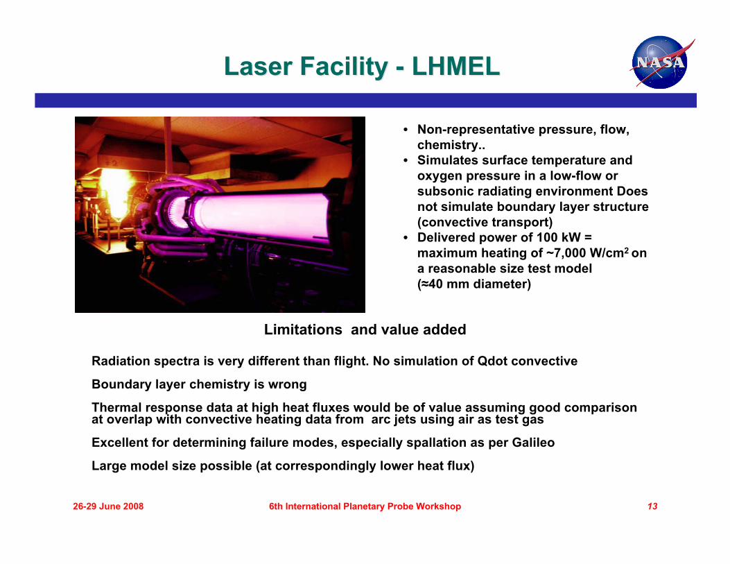
• Non-representative pressure, flow,chemistry..
• Simulates surface temperature andoxygen pressure in a low-flow orsubsonic radiating environment Doesnot simulate boundary layer structure(convective transport)
• Delivered power of 100 kW =maximum heating of ~7,000 W/cm2 ona reasonable size test model(≈40 mm diameter)
Laser Facility - LHMELLaser Facility - LHMEL
Limitations and value added
Radiation spectra is very different than flight. No simulation of Qdot convective
Boundary layer chemistry is wrong
Thermal response data at high heat fluxes would be of value assuming good comparisonat overlap with convective heating data from arc jets using air as test gas
Excellent for determining failure modes, especially spallation as per Galileo
Large model size possible (at correspondingly lower heat flux)

International Planetary Probe Workshop 6
26-29 June 2008 146th International Planetary Probe Workshop
2-D Test Configuration
Carbon Phenolic Test Sample after13-sec. Exposure
Based on previous work done at the Aerotherm1-MW APG Facility†, where the test modelformed the throat region of a 2-D nozzle withsample nominal dimensions of 1.0 inch wide x0.95 inch long. Lead-in ramp roughened topromote turbulent flow. 75% H2 / 25% He(Jupiter nominal) test gas shown as example.Facility can operate on wide variety of testgases including air, nitrogen, argon, carbondioxide, and hydrogen/helium.
ARC Development Arcjet Facility (DAF) TestingARC Development Arcjet Facility (DAF) Testing2-D Nozzle Test Configuration2-D Nozzle Test Configuration
† Aerotherm TM-76-106, March 1976
Predicted Heating Distribution on Test Model

International Planetary Probe Workshop 6
26-29 June 2008 156th International Planetary Probe Workshop
Proposed DAF Testing in COProposed DAF Testing in CO22Stagnation Test ConfigurationStagnation Test Configuration
† by John Balboni, NASA/ARC
Maximum heating rate at:
• Maximum stagnation pressureqcw: ~2,500 W/cm2
PT2: ~2.5 atmHcenterline: ~30 MJ/kg
• Maximum centerline enthalpyqcw: ~2,500 W/cm2
PT2: ~0.65 atmHcenterline: ~58 MJ/kg
Performance predictions† for DAF with various conical nozzles,subsonic electrode configuration, 95% CO2 / 5% N2 (molar) testgas, and 2.54 cm diameter test model:
International Planetary Probe Workshop 6
26-29 June 2008 166th International Planetary Probe Workshop
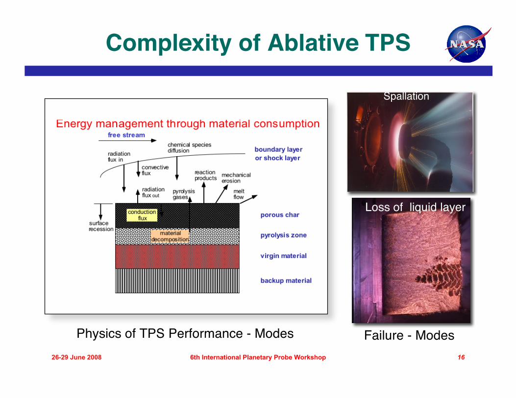
Complexity of Ablative TPS
Spallation
Loss of liquid layer
Physics of TPS Performance - Modes Failure - Modes
International Planetary Probe Workshop 6
26-29 June 2008 176th International Planetary Probe Workshop
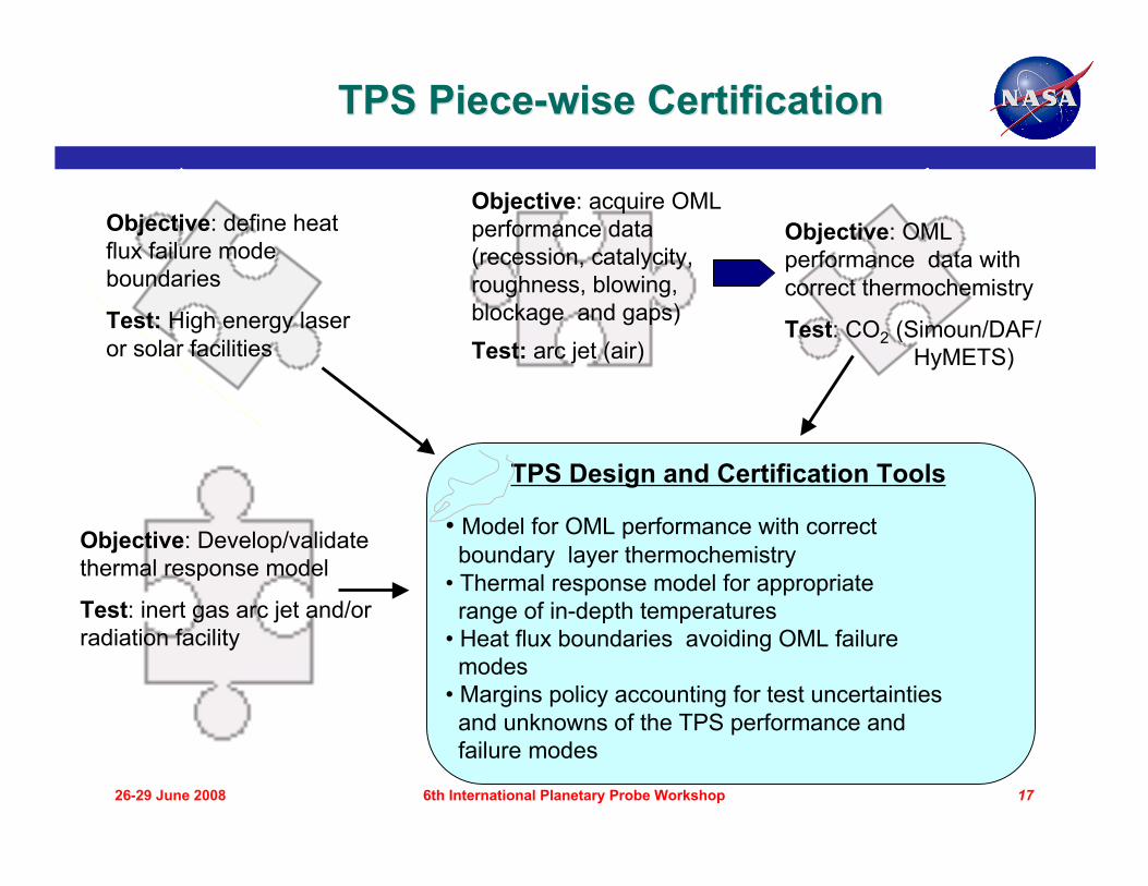
Objective: define heatflux failure modeboundaries
Test: High energy laseror solar facilities
Objective: acquire OMLperformance data(recession, catalycity,roughness, blowing,blockage and gaps)Test: arc jet (air)
Objective: OMLperformance data withcorrect thermochemistry
Test: CO2 (Simoun/DAF/ HyMETS)
Objective: Develop/validatethermal response model
Test: inert gas arc jet and/orradiation facility
TPS Piece-wise CertificationTPS Piece-wise Certification
TPS Design and Certification Tools
• Model for OML performance with correct boundary layer thermochemistry• Thermal response model for appropriate range of in-depth temperatures• Heat flux boundaries avoiding OML failure modes• Margins policy accounting for test uncertainties and unknowns of the TPS performance and failure modes

International Planetary Probe Workshop 6
26-29 June 2008 186th International Planetary Probe Workshop
Carbon Phenolic for Venus Heritage carbon phenolic (P-V and Galileo) no longer manufactured
– Very limited supply of heritage CP– Current CP employs carbon cloth derived from new rayon source– Limited arc jet tests show performance similar to heritage
Test in high energy laser facility (e.g., LHMEL) to demonstrate capability atmax combined heat flux
– Verify absence of failure modes Test in CO2 arc jet (e.g., DAF) to demonstrate applicability of theoretical
thermochemical ablation models to performance in Venus atmosphere Validate/update heritage in-depth thermal response models via arc jet tests of
instrumented samples at well-defined conditions (e.g., IHF) Combine surface ablation and in-depth thermal response models into Venus
entry design model for carbon phenolic Heat shield design and certification is easier with heritage C-P
– Pioneer-Venus and Galileo experience– Robust; applicable for conditions far exceeding any Venus mission and is truly off
the shelf.

International Planetary Probe Workshop 6
26-29 June 2008 196th International Planetary Probe Workshop
PICA/Avcoat/ACC for Venus PICA is the baseline forebody TPS for Orion’s Crew Exploration Vehicle
(CEV) and MSL– Successfully used as the forebody heatshield on Stardust
Avcoat 5026-39/HC-G is the alternate forebody TPS for Orion– Successfully used on Apollo 40 years ago
ACC has limited demonstrated performance capability– Failure modes not well-established
The first two materials are being extensively evaluated by the CEVAdvanced Development Program via testing, analysis and manufacturingdemonstrations
– An extensive database has been developed for PICA; failure modes areunderstood (do not exceed 1500 W/cm2 and 1-1.5 atm); validated designmodels available
– A more limited database is being developed for Avcoat to demonstrate thatproperties and performance are consistent with heritage material
Attractive for out-of-orbit and/or aerocapture segment of the design– Leverage on-going CEV Orion developments for PICA and AVCOAT– C-C will require failure mode testing and analysis development

International Planetary Probe Workshop 6
26-29 June 2008 206th International Planetary Probe Workshop
Mid-Density (Low TRL/IRL) TPSDevelopment Challenges
Available “off-the-shelf” materials applicable to TPS for planetaryprobes are very limited
Several mid-density (480-960 kg/m3) ablative materials are attractivecandidates for some planetary missions
– PhenCarb (ARA), Densified PICA†, mid-density C-P† andBPA (Boeing)
– More robust than low density materials, i.e., capable of reliableperformance at higher heat flux and pressure
– TPS mass savings in comparison to high density materials,e.g., carbon phenolic
Qualification and certification of these “new” materialsfor mission use would require a significant amount of testing,modeling and analysis
– Reliability requirements << crewed missions– Who would sponsor such development?
†Modest development being sponsored by NASA’s Hypersonics Program

International Planetary Probe Workshop 6
26-29 June 2008 216th International Planetary Probe Workshop
Conclusions/RecommendationsConclusions/Recommendations
Test as you fly and fly as you test is generally not possible for TPS
Approach for affordable TPS development and certificationfor Venus Direct entry and Aerocapture has been outlined– Define mission scenarios– Evaluate candidate TPS– Evaluate arc jet and other testing capabilities– Piecewise determination of material properties and
failure modesCertification by combination of testing and analysis
Recommendations:– Near-term Venus missions: Cost-effective and robust TPS solution
is heritage carbon phenolic– Need CO2 arc jet capability relevant for Venus conditions -
complete DAF to support TPS testing for Venus missions– Optimal TPS solution for future Venus missions requires a
dedicated TPS advanced development program