international standard 15765-3 - pudn.comread.pudn.com/downloads506/doc/2103567/iso_15765-3.pdf ·...
TRANSCRIPT

Reference numberISO 15765-3:2004(E)
© ISO 2004
INTERNATIONAL STANDARD
ISO15765-3
First edition2004-10-15
Road vehicles — Diagnostics on Controller Area Networks (CAN) — Part 3: Implementation of unified diagnostic services (UDS on CAN)
Véhicules routiers — Diagnostic sur gestionnaire de réseau de communication (CAN) —
Partie 3: Mise en œuvre des services de diagnostic unifiés (SDU sur CAN)
B55EB1B3C7662F79D1B59483A53B9F2F82C98BEEB7939EA95CF14FFEE5FB13B925D84A2690B319CCC3FB33EC1A0EE19ACE32C3AD48AA2003E27076E26B823E886461F4EB146348E75A2E06040CBB18
No
rmen
-Do
wn
load
-Beu
th-M
OW
AG
Gm
bH
-Kd
Nr.
2337
322-
LfN
r.29
8861
9001
-200
5-11
-07
16:1
6

ISO 15765-3:2004(E)
PDF disclaimer This PDF file may contain embedded typefaces. In accordance with Adobe's licensing policy, this file may be printed or viewed but shall not be edited unless the typefaces which are embedded are licensed to and installed on the computer performing the editing. In downloading this file, parties accept therein the responsibility of not infringing Adobe's licensing policy. The ISO Central Secretariat accepts no liability in this area.
Adobe is a trademark of Adobe Systems Incorporated.
Details of the software products used to create this PDF file can be found in the General Info relative to the file; the PDF-creation parameters were optimized for printing. Every care has been taken to ensure that the file is suitable for use by ISO member bodies. In the unlikely event that a problem relating to it is found, please inform the Central Secretariat at the address given below.
© ISO 2004 All rights reserved. Unless otherwise specified, no part of this publication may be reproduced or utilized in any form or by any means, electronic or mechanical, including photocopying and microfilm, without permission in writing from either ISO at the address below or ISO's member body in the country of the requester.
ISO copyright office Case postale 56 • CH-1211 Geneva 20 Tel. + 41 22 749 01 11 Fax + 41 22 749 09 47 E-mail [email protected] Web www.iso.org
Published in Switzerland
ii © ISO 2004 – All rights reserved
B55EB1B3C7662F79D1B59483A53B9F2F82C98BEEB7939EA95CF14FFEE5FB13B925D84A2690B319CCC3FB33EC1A0EE19ACE32C3AD48AA2003E27076E26B823E886461F4EB146348E75A2E06040CBB18
No
rmen
-Do
wn
load
-Beu
th-M
OW
AG
Gm
bH
-Kd
Nr.
2337
322-
LfN
r.29
8861
9001
-200
5-11
-07
16:1
6
ISO 15765-3:2004(E)
© ISO 2004 – All rights reserved iii
Contents Page
Foreword............................................................................................................................................................. v Introduction ....................................................................................................................................................... vi 1 Scope...................................................................................................................................................... 1 2 Normative references ........................................................................................................................... 1 3 Terms, definitions and abbreviated terms.......................................................................................... 2 4 Conventions .......................................................................................................................................... 2 5 Unified diagnostic services (UDS) applicability to OSI model ......................................................... 2 6 Application and session layers ........................................................................................................... 2 6.1 Application layer services.................................................................................................................... 2 6.2 Application layer protocol.................................................................................................................... 2 6.3 Application layer and diagnostic session management timing....................................................... 2 6.3.1 General ................................................................................................................................................... 2 6.3.2 Application layer timing parameter definitions ................................................................................. 4 6.3.3 Session layer timing parameter definitions ....................................................................................... 6 6.3.4 Client and server timer resource requirements................................................................................. 6 6.3.5 Detailed timing parameter descriptions ............................................................................................. 9 6.3.6 Error handling ..................................................................................................................................... 27 7 Network layer interface....................................................................................................................... 29 7.1 General information ............................................................................................................................ 29 7.2 FlowControl N_PCI parameter definition.......................................................................................... 29 7.3 Mapping of A_PDU onto N_PDU for message transmission.......................................................... 29 7.4 Mapping of N_PDU onto A_PDU for message reception ................................................................ 29 8 Standardized diagnostic CAN identifiers ......................................................................................... 30 8.1 Legislated 11 bit OBD CAN identifiers.............................................................................................. 30 8.2 Legislated 29 bit OBD CAN identifiers.............................................................................................. 30 8.3 Enhanced diagnostics 29 bit CAN identifiers .................................................................................. 30 8.3.1 General information ............................................................................................................................ 30 8.3.2 Structure of 29 bit CAN identifier ...................................................................................................... 31 8.3.3 Structure of address ........................................................................................................................... 33 8.3.4 Message retrieval ................................................................................................................................ 35 8.3.5 Routing................................................................................................................................................. 36 9 Diagnostic services implementation................................................................................................. 40 9.1 Unified diagnostic services overview ............................................................................................... 40 9.2 Diagnostic and communication control functional unit ................................................................. 42 9.2.1 DiagnosticSessionControl (10 hex) service..................................................................................... 42 9.2.2 ECUReset (11 hex) service................................................................................................................. 42 9.2.3 SecurityAccess (27 hex) service ....................................................................................................... 43 9.2.4 CommunicationControl (28 hex) service .......................................................................................... 43 9.2.5 TesterPresent (3E hex) service.......................................................................................................... 43 9.2.6 SecuredDataTransmission (84 hex) service..................................................................................... 44 9.2.7 ControlDTCSetting (85 hex) service.................................................................................................. 44 9.2.8 ResponseOnEvent (86 hex) service .................................................................................................. 44 9.2.9 LinkControl (87 hex) service.............................................................................................................. 47 9.3 Data transmission functional unit ..................................................................................................... 47 9.3.1 ReadDataByIdentifier (22 hex) service.............................................................................................. 47 9.3.2 ReadMemoryByAddress (23 hex) service ........................................................................................ 47 9.3.3 ReadScalingDataByIdentifier(24 hex) service.................................................................................. 48
B55EB1B3C7662F79D1B59483A53B9F2F82C98BEEB7939EA95CF14FFEE5FB13B925D84A2690B319CCC3FB33EC1A0EE19ACE32C3AD48AA2003E27076E26B823E886461F4EB146348E75A2E06040CBB18
No
rmen
-Do
wn
load
-Beu
th-M
OW
AG
Gm
bH
-Kd
Nr.
2337
322-
LfN
r.29
8861
9001
-200
5-11
-07
16:1
6

ISO 15765-3:2004(E)
iv © ISO 2004 – All rights reserved
9.3.4 ReadDataByPeriodicIdentifier (2A hex) service ...............................................................................48 9.3.5 DynamicallyDefineDataIdentifier (2C hex) service...........................................................................54 9.3.6 WriteDataByIdentifier (2E hex) service .............................................................................................54 9.3.7 WriteMemoryByAddress (3D hex) service........................................................................................54 9.4 Stored data transmission functional unit .........................................................................................54 9.4.1 ReadDTCInformation (19 hex) service ..............................................................................................54 9.4.2 ClearDiagnosticInformation (14 hex) service ...................................................................................56 9.5 Input/Output control functional unit..................................................................................................56 9.5.1 InputOutputControlByIdentifier (2F hex) service.............................................................................56 9.6 Remote activation of routine functional unit ....................................................................................56 9.6.1 RoutineControl (31 hex) service ........................................................................................................56 9.7 Upload/Download functional unit ......................................................................................................57 9.7.1 RequestDownload (34 hex) service...................................................................................................57 9.7.2 RequestUpload (35 hex) service ........................................................................................................57 9.7.3 TransferData (36 hex) service ............................................................................................................57 9.7.4 RequestTransferExit (37 hex) service ...............................................................................................57 10 Non-volatile server memory programming process........................................................................58 10.1 General information ............................................................................................................................58 10.2 Detailed programming sequence.......................................................................................................61 10.2.1 Programming phase #1 — Download of application software and/or application data...............61 10.2.2 Programming phase #2 — Server configuration..............................................................................66 10.3 Server reprogramming requirements................................................................................................69 10.3.1 Programmable servers and their categories ....................................................................................69 10.3.2 Requirements for all servers to support programming...................................................................70 10.3.3 Requirements for programmable servers to support programming .............................................70 10.3.4 Software, data identification and fingerprints..................................................................................74 10.3.5 Server routine access .........................................................................................................................77 10.4 Non-volatile server memory programming message flow examples ............................................78 10.4.1 General information ............................................................................................................................78 10.4.2 Programming phase #1 — Pre-Programming step ..........................................................................78 10.4.3 Programming phase #1 — Programming step .................................................................................79 10.4.4 Programming phase #1 — Post-Programming step ........................................................................86 Annex A (normative) Network configuration dataIdentifier definitions ......................................................87 Bibliography......................................................................................................................................................92
B55EB1B3C7662F79D1B59483A53B9F2F82C98BEEB7939EA95CF14FFEE5FB13B925D84A2690B319CCC3FB33EC1A0EE19ACE32C3AD48AA2003E27076E26B823E886461F4EB146348E75A2E06040CBB18
No
rmen
-Do
wn
load
-Beu
th-M
OW
AG
Gm
bH
-Kd
Nr.
2337
322-
LfN
r.29
8861
9001
-200
5-11
-07
16:1
6

ISO 15765-3:2004(E)
© ISO 2004 – All rights reserved v
Foreword
ISO (the International Organization for Standardization) is a worldwide federation of national standards bodies (ISO member bodies). The work of preparing International Standards is normally carried out through ISO technical committees. Each member body interested in a subject for which a technical committee has been established has the right to be represented on that committee. International organizations, governmental and non-governmental, in liaison with ISO, also take part in the work. ISO collaborates closely with the International Electrotechnical Commission (IEC) on all matters of electrotechnical standardization.
International Standards are drafted in accordance with the rules given in the ISO/IEC Directives, Part 2.
The main task of technical committees is to prepare International Standards. Draft International Standards adopted by the technical committees are circulated to the member bodies for voting. Publication as an International Standard requires approval by at least 75 % of the member bodies casting a vote.
Attention is drawn to the possibility that some of the elements of this document may be the subject of patent rights. ISO shall not be held responsible for identifying any or all such patent rights.
ISO 15765-3 was prepared by Technical Committee ISO/TC 22, Road vehicles, Subcommittee SC 3, Electrical and electronic equipment.
ISO 15765 consists of the following parts, under the general title Road vehicles — Diagnostics on Controller Area Networks (CAN):
Part 1: General information
Part 2: Network layer services
Part 3: Implementation of unified diagnostic services (UDS on CAN)
Part 4: Requirements for emissions-related systems
B55EB1B3C7662F79D1B59483A53B9F2F82C98BEEB7939EA95CF14FFEE5FB13B925D84A2690B319CCC3FB33EC1A0EE19ACE32C3AD48AA2003E27076E26B823E886461F4EB146348E75A2E06040CBB18
No
rmen
-Do
wn
load
-Beu
th-M
OW
AG
Gm
bH
-Kd
Nr.
2337
322-
LfN
r.29
8861
9001
-200
5-11
-07
16:1
6

ISO 15765-3:2004(E)
vi © ISO 2004 – All rights reserved
Introduction
This part of ISO 15765 has been established in order to enable the implementation of unified diagnostic services, as specified in ISO 14229-1, on controller area networks (UDS on CAN).
To achieve this, it is based on the Open Systems Interconnection (OSI) Basic Reference Model specified in ISO/IEC 7498 and ISO/IEC 10731, which structures communication systems into seven layers. When mapped on this model, the services specified by ISO 15765 are divided into
unified diagnostic services (layer 7), specified in this part of ISO 15765,
network layer services (layer 3), specified in ISO 15765-2,
CAN services (layers 1 and 2), specified in ISO 11898,
in accordance with Table 1.
Table 1 — Enhanced and legislated OBD diagnostic specifications applicable to the OSI layers
Open Systems Interconnection
(OSI) layers
Vehicle manufacturer enhanced diagnostics
Legislated on-board diagnostics
(OBD)
Diagnostic application User defined ISO 15031-5
Application layer ISO 15765-3 ISO 15031-5
Presentation layer N/A N/A
Session layer ISO 15765-3 N/A
Transport layer N/A N/A
Network layer ISO 15765-2 ISO 15765-4
Data link layer ISO 11898-1 ISO 15765-4
Physical layer User defined ISO 15765-4
B55EB1B3C7662F79D1B59483A53B9F2F82C98BEEB7939EA95CF14FFEE5FB13B925D84A2690B319CCC3FB33EC1A0EE19ACE32C3AD48AA2003E27076E26B823E886461F4EB146348E75A2E06040CBB18
No
rmen
-Do
wn
load
-Beu
th-M
OW
AG
Gm
bH
-Kd
Nr.
2337
322-
LfN
r.29
8861
9001
-200
5-11
-07
16:1
6

INTERNATIONAL STANDARD ISO 15765-3:2004(E)
© ISO 2004 – All rights reserved 1
Road vehicles — Diagnostics on Controller Area Networks (CAN) —
Part 3: Implementation of unified diagnostic services (UDS on CAN)
1 Scope
This part of ISO 15765 specifies the implementation of a common set of unified diagnostic services (UDS), in accordance with ISO 14229-1, on controller area networks (CAN) in road vehicles as specified in ISO 11898. It gives the diagnostic services and server memory programming requirements for all in-vehicle servers connected to a CAN network and external test equipment. It does not specify any requirement for the in-vehicle CAN bus architecture.
2 Normative references
The following referenced documents are indispensable for the application of this document. For dated references, only the edition cited applies. For undated references, the latest edition of the referenced document (including any amendments) applies.
ISO 14229-1, Road vehicles — Unified diagnostic services (UDS) — Part 1: Specification and requirements
ISO 11898-1, Road vehicles — Controller area network (CAN) — Part 1: Data link layer and physical signalling
ISO 11898-2, Road vehicles — Controller area network (CAN) — Part 2: High-speed medium access unit
ISO 11898-3, Road vehicles — Controller area network (CAN) — Part 3: Low-speed, fault-tolerant, medium dependent interface1)
ISO 15031-6, Road vehicles — Communication between vehicle and external equipment for emissions-related diagnostics — Part 6: Diagnostic trouble code definitions1)
ISO 15765-1, Road vehicles — Diagnostics on controller area network (CAN) — Part 1: General information
ISO 15765-2, Road vehicles — Diagnostics on controller area network (CAN) — Part 2: Network layer service1)
ISO 15765-4, Road vehicles — Diagnostics on controller area network (CAN) — Part 4: Requirements for emissions-related systems1)
SAE J1939-21, Recommended practice for a serial control and communications vehicle network — Data link layer2)
1) To be published.
2) Society of Automotive Engineers standard.
B55EB1B3C7662F79D1B59483A53B9F2F82C98BEEB7939EA95CF14FFEE5FB13B925D84A2690B319CCC3FB33EC1A0EE19ACE32C3AD48AA2003E27076E26B823E886461F4EB146348E75A2E06040CBB18
No
rmen
-Do
wn
load
-Beu
th-M
OW
AG
Gm
bH
-Kd
Nr.
2337
322-
LfN
r.29
8861
9001
-200
5-11
-07
16:1
6

ISO 15765-3:2004(E)
2 © ISO 2004 – All rights reserved
3 Terms, definitions and abbreviated terms
For the purposes of this document, the terms and definitions given in ISO 14229-1, ISO 15765-1 and ISO 15765-2 and the following abbreviated terms apply.
DA destination address
ID identifier
DLC data length code
GW gateway
LSB least significant bit
MSB most significant bit
NA network address
SA source address
SM subnet mask
TOS type of service
4 Conventions
This part of ISO 15765 is based on conventions defined in ISO 14229-1, which are guided by OSI Service Conventions (see ISO/TR 8509) as they apply for diagnostic services.
5 Unified diagnostic services (UDS) applicability to OSI model
See Figure 1.
6 Application and session layers
6.1 Application layer services
This part of ISO 15765 uses the application layer services as defined in ISO 14229-1 for client-server based systems to perform functions such as test, inspection, monitoring, diagnosis or programming of on-board vehicle servers.
6.2 Application layer protocol
This part of ISO 15765 uses the application layer protocol as defined in ISO 14229-1.
6.3 Application layer and diagnostic session management timing
IMPORTANT — Any N_USData.indication with <N_Result> not equal to N_OK that is generated in the server shall not result in a response message from the server application.
6.3.1 General
The following specifies the application layer and session layer timing parameters and how they are handled for the client and the server.
B55EB1B3C7662F79D1B59483A53B9F2F82C98BEEB7939EA95CF14FFEE5FB13B925D84A2690B319CCC3FB33EC1A0EE19ACE32C3AD48AA2003E27076E26B823E886461F4EB146348E75A2E06040CBB18
No
rmen
-Do
wn
load
-Beu
th-M
OW
AG
Gm
bH
-Kd
Nr.
2337
322-
LfN
r.29
8861
9001
-200
5-11
-07
16:1
6

ISO 15765-3:2004(E)
© ISO 2004 – All rights reserved 3
Figure 1 — Implementation of UDS on CAN in OSI model
The following communication scenarios shall be distinguished from one another:
a) physical communication during
1) default session, and
2) non-default session — session handling required;
b) functional communication during
1) default session, and
2) non-default session — session handling required.
For all cases, the possibility of requesting an enhanced response-timing window by the server via a negative response message, including a response code 78 hex, shall be considered.
The network layer services as defined in ISO 15765-2 are used to perform the application layer and diagnostic session management timing in the client and the server.
B55EB1B3C7662F79D1B59483A53B9F2F82C98BEEB7939EA95CF14FFEE5FB13B925D84A2690B319CCC3FB33EC1A0EE19ACE32C3AD48AA2003E27076E26B823E886461F4EB146348E75A2E06040CBB18
No
rmen
-Do
wn
load
-Beu
th-M
OW
AG
Gm
bH
-Kd
Nr.
2337
322-
LfN
r.29
8861
9001
-200
5-11
-07
16:1
6

ISO 15765-3:2004(E)
4 © ISO 2004 – All rights reserved
6.3.2 Application layer timing parameter definitions
The application layer timing parameter values for the default diagnostic session shall be in accordance with Table 2.
Table 2 — Application layer timing parameter definitions for the defaultSession
Timing parameter
Description Type Min. Max.
P2CAN_Client
Timeout for the client to wait after the successful transmission of a request message (indicated via N_USData.con) for the start of incoming response messages (N_USDataFirstFrame.ind of a multi-frame message or N_USData.ind of a SingleFrame message).
Timer reloadvalue P2CAN_Server_max
+ ∆P2CAN
N/A a
P2*CAN_Client
Enhanced timeout for the client to wait after the reception of a negative response message with response code 78 hex (indicated via N_USData.ind) for the start of incoming response messages (N_USDataFirstFrame.ind of a multi-frame message or N_USData.ind of a SingleFrame message).
Timer reloadvalue P2*CAN_Server_max
+ ∆P2CAN_rsp
N/A b
P2CAN_Server Performance requirement for the server to start with the response message after the reception of a request message (indicated via N_USData.ind).
Performancerequirement 0 50 ms
P2*CAN_Server
Performance requirement for the server to start with the response message after the transmission of a negative response message (indicated via N_USData.con) with response code 78 hex (enhanced response timing).
Performancerequirement 0 c 5000 ms
P3CAN_Client_Phys
Minimum time for the client to wait after the successful transmission of a physically addressed request message (indicated via N_USData.con) with no response required before it can transmit the next physically addressed request message (see 6.3.5.3).
Timer reloadvalue
P2CAN_Server_max N/A d
P3CAN_Client_Func
Minimum time for the client to wait after the successful transmission of a functionally addressed request message (indicated via N_USData.con) before it can transmit the next functionally addressed request message in case no response is required or the requested data is only supported by a subset of the functionally addressed servers (see 6.3.5.3).
Timer reloadvalue
P2CAN_Server_max N/A d
a The maximum time a client waits for a response message to start is at the discretion of the client, provided that P2CAN_Client is greater than the specified minimum value of P2CAN_Client.
b The value that a client uses for P2*CAN_Client is at the discretion of the client, provided it is greater than the specified minimum value of P2*CAN_Client.
c During the enhanced response timing, the minimum time between the transmission of consecutive negative messages, each with response code 78 hex, shall be ½ P2*CAN_Server_max, with a maximum tolerance of ± 20% of P2*CAN_Server_max..
d The maximum time a client waits until it transmits the next request message is at the discretion of the client, provided that for non-default sessions the S3Server timing is kept active in the server(s).
B55EB1B3C7662F79D1B59483A53B9F2F82C98BEEB7939EA95CF14FFEE5FB13B925D84A2690B319CCC3FB33EC1A0EE19ACE32C3AD48AA2003E27076E26B823E886461F4EB146348E75A2E06040CBB18
No
rmen
-Do
wn
load
-Beu
th-M
OW
AG
Gm
bH
-Kd
Nr.
2337
322-
LfN
r.29
8861
9001
-200
5-11
-07
16:1
6

ISO 15765-3:2004(E)
© ISO 2004 – All rights reserved 5
The parameter ∆P2CAN considers any system network design-dependent delays such as delays introduced by gateways and bus bandwidth plus a safety margin (e.g. 50 % of worst case). The worst-case scenario (transmission time necessary for one “round trip” from client to server and back from server to client), based on system design, is impacted by
a) the number of gateways involved,
b) CAN frame transmission time (baud rate),
c) CAN bus utilization, and
d) the CAN device driver implementation method (polling vs interrupt) and processing time of the network layer.
The value of ∆P2CAN is divided into the time to transmit the request to the addressed server and the time to transmit the response to the client:
∆P2CAN = ∆P2CAN_Req + ∆P2CAN_Rsp
Figure 2 provides an example of how ∆P2CAN can be composed.
Figure 2 — Example for ∆∆∆∆P2CAN — SingleFrame request and response message
NOTE For the sake of simplicity in describing the timing parameters, in all the figures that follow it is assumed that the client and the server are located on the same network. All descriptions and figures are presented in a time-related sequential order.
B55EB1B3C7662F79D1B59483A53B9F2F82C98BEEB7939EA95CF14FFEE5FB13B925D84A2690B319CCC3FB33EC1A0EE19ACE32C3AD48AA2003E27076E26B823E886461F4EB146348E75A2E06040CBB18
No
rmen
-Do
wn
load
-Beu
th-M
OW
AG
Gm
bH
-Kd
Nr.
2337
322-
LfN
r.29
8861
9001
-200
5-11
-07
16:1
6

ISO 15765-3:2004(E)
6 © ISO 2004 – All rights reserved
6.3.3 Session layer timing parameter definitions
When a diagnostic session other than the defaultSession is started, then a session handling is required which is achieved via the session layer timing parameter given in Table 3.
Table 3 — Session layer timing parameter definitions
Recommended timeout
Timeout Timing
parameter Description Type ms ms
S3Client
Time between functionally addressed TesterPresent (3E hex) request messages transmitted by the client to keep a diagnostic session other than the defaultSession active in multiple servers (functional communication) or maximum time between physically transmitted request messages to a single server (physical communication).
Timer reloadvalue
2 000 ms 4 000 ms
S3Server Time for the server to keep a diagnostic session other than the defaultSession active while not receiving any diagnostic request message.
Timer reloadvalue
N/A 5 000 ms
Furthermore, the server might change its application layer timings P2CAN_Server and P2*CAN_Server when transitioning into a non-default session in order to achieve a certain performance or to compensate restrictions which might apply during a non-default diagnostic session. The applicable timing parameters for a non-default diagnostic session are reported in the DiagnosticSessionControl positive response message in the case where a response is required to be transmitted (see service description in 9.2.1) or have to be known in advance by the client in case no response is required to be transmitted. When the client starts a non-default session functionally, then it shall adapt to the timing parameters of the responding servers.
Table 4 defines the conditions for the client and the server to start/restart its S3Client/S3Server timer. For the client a periodically transmitted functionally addressed TesterPresent (3E hex) request message shall be distinguished from a sequentially transmitted physically addressed TesterPresent (3E hex) request message, which is only transmitted in case of the absence of any other diagnostic request message. For the server there is no need to distinguish between that kind of TesterPresent (3E hex) handling. Furthermore, Table 4 shows that the S3Server timer handling is based on the network layer service primitives, which means that the S3Server timer is also restarted upon the reception of a diagnostic request message that is not supported by the server.
6.3.4 Client and server timer resource requirements
The timer resource required for the client and the server to fulfil the above given timing requirements during the default session and any non-default session shall be in accordance with Tables 5 and 6 list. During a non-default session, the additional timer resource requirements given in Table 6 shall apply for the client and the server.
B55EB1B3C7662F79D1B59483A53B9F2F82C98BEEB7939EA95CF14FFEE5FB13B925D84A2690B319CCC3FB33EC1A0EE19ACE32C3AD48AA2003E27076E26B823E886461F4EB146348E75A2E06040CBB18
No
rmen
-Do
wn
load
-Beu
th-M
OW
AG
Gm
bH
-Kd
Nr.
2337
322-
LfN
r.29
8861
9001
-200
5-11
-07
16:1
6

ISO 15765-3:2004(E)
© ISO 2004 – All rights reserved 7
Table 4 — Session layer timing start/stop conditions for the client and the server
Timing Parameter
Action Physical and functional communication,using functionally addressed,
periodically transmitted TesterPresent request message
Physical communication only, using a physically addressed,
sequentially transmitted TesterPresent request message
N_USData.con that indicates the completion of the DiagnosticSessionControl (10 hex) request message in case no response is required. Initial
start
N_USData.con that indicates the completion of the DiagnosticSessionControl (10 hex) request message. This is only true for if the session type is a non-default session.
N_USData.ind that indicates the reception of the DiagnosticSessionControl (10 hex) response message in case a response is required.
N_USData.con that indicates the completion of any request message in case no response is required.
N_USData.ind that indicates the reception of any response message in case a response is required.
S3Client
Subsequentstart
N_USData.con that indicates the completion of the functionally addressed TesterPresent (3E hex) request message, which is transmitted each time the S3Client timer times out. N_USData.ind that indicates an error during
the reception of a multi-frame response message.
N_USData.con that indicates the completion of the transmission of a DiagnosticSessionControl positive response message for a transition from the default session to a non-default session, in case a response message is required.
Initial start Successful completion of the requested action of the service DiagnosticSessionControl (10 hex) for a transition from the default session to a non-default session, in case no response message is required/allowed.
Subsequentstop
N_USDataFirstFrame.ind that indicates the start of a multi-frame request message or N_USData.ind that indicates the reception of any SingleFrame request message. If the defaultSession is active, the S3Server timer is disabled.
N_USData.con that indicates the completion of any response message that concludes a service execution (final response message) in case a response message is required/allowed to be transmitted (this includes positive and negative response messages). A negative response with response code 78 hex does not restart the S3Server timer.
Completion of the requested action (service conclusion) in case no response message (positive and negative) is required/allowed.
N_USData.ind that indicates an error during the reception of a multi-frame request message.
S3Server
Subsequentstart
See 6.3.5.4 for further details regarding the S3Server handling in the server when the server is requested to transmit unsolicited response message such as periodic data or responses based on an event.
B55EB1B3C7662F79D1B59483A53B9F2F82C98BEEB7939EA95CF14FFEE5FB13B925D84A2690B319CCC3FB33EC1A0EE19ACE32C3AD48AA2003E27076E26B823E886461F4EB146348E75A2E06040CBB18
No
rmen
-Do
wn
load
-Beu
th-M
OW
AG
Gm
bH
-Kd
Nr.
2337
322-
LfN
r.29
8861
9001
-200
5-11
-07
16:1
6

ISO 15765-3:2004(E)
8 © ISO 2004 – All rights reserved
Table 5 — Timer resources requirements during defaultSession
Timing parameter
Client Server
P2CAN_Client
A single timer is required for each logical communication channel (physical and functional communication), e.g. each point-to-point communication requires a separate communication channel.
N/A
P2CAN_Server N/A
An optional timer might be required for the enhanced response timing in order to ensure that subsequent negative response messages with response code 78 hex are transmitted prior to the expiration of P2*CAN_Server.
P3CAN_Physical A single timer is required per logical physical communication channel. N/A
P3CAN_Functional A single timer is required per logical functional communication channel. N/A
Table 6 — Additional timer resources requirements during non-defaultSession
Timing Parameter Client Server
A single timer is required when using a periodically transmitted, functionally addressed TesterPresent (3E) hex request message to keep the servers in a non-defaultSession. There is no need for additional timers per activated diagnostic sessions.
N/A
S3Client A single timer is required for each point-to-point communication channel when using a sequentially transmitted, physically addressed TesterPresent (3E) hex request message to keep a single server in a non-defaultSession in case of the absence of another diagnostic request message then.
S3Server N/A A single timer is required in the server, because only a single diagnostic session can be active at a time in a single server.
B55EB1B3C7662F79D1B59483A53B9F2F82C98BEEB7939EA95CF14FFEE5FB13B925D84A2690B319CCC3FB33EC1A0EE19ACE32C3AD48AA2003E27076E26B823E886461F4EB146348E75A2E06040CBB18
No
rmen
-Do
wn
load
-Beu
th-M
OW
AG
Gm
bH
-Kd
Nr.
2337
322-
LfN
r.29
8861
9001
-200
5-11
-07
16:1
6

ISO 15765-3:2004(E)
© ISO 2004 – All rights reserved 9
6.3.5 Detailed timing parameter descriptions
6.3.5.1 Physical communication
6.3.5.1.1 Physical communication during defaultSession
Figure 3 graphically depicts the timing handling in the client and the server for a physically addressed request message during the default session.
a The diagnostic application of the client starts the transmission of the request message by issuing a N_USData.req to its network layer. The network layer transmits the request message to the server. The request message can either be a single-frame message or a multi-frame message. b In the case of a multi-frame message, the start of the request is indicated in the server via N_USDataFF.ind that is issued by its network layer. c The completion of the request message is indicated in the client via N_USData.con. When receiving the N_USData.con the client starts its P2CAN_Client timer, using the default reload value P2CAN_Client. The value of the P2CAN_Client timer shall consider any latency that is involved based on the vehicle network design (communication over gateways, bus bandwidth, etc.). For simplicity, the figure assumes that the client and the server are located on the same network. d The completion of the request message is indicated in the server via the N_USData.ind. e The server is required to start with its response message within P2CAN_Server after the reception of N_USData.ind. This means that, in the case of a multi-frame response message, the FirstFrame shall be sent within P2CAN_Server and, for single-frame response messages, that the SingleFrame shall be sent within P2CAN_Server. f In the case of a multi-frame response message, the reception of the FirstFrame is indicated in the client via the N_USDataFF.ind of its network layer. When receiving the FirstFrame indication, the client stops its P2CAN_Client timer. g The network layer will generate a final N_USData.ind in case the complete message is received or an error occurred during the reception. In case of a single-frame response message, the reception of the SingleFrame is indicated in the client via a single N_USData.ind. When receiving this single frame indication, the client stops its P2CAN_Client timer. h The completion of the response message is indicated in the server via N_USData.con.
Figure 3 — Physical communication during default session
B55EB1B3C7662F79D1B59483A53B9F2F82C98BEEB7939EA95CF14FFEE5FB13B925D84A2690B319CCC3FB33EC1A0EE19ACE32C3AD48AA2003E27076E26B823E886461F4EB146348E75A2E06040CBB18
No
rmen
-Do
wn
load
-Beu
th-M
OW
AG
Gm
bH
-Kd
Nr.
2337
322-
LfN
r.29
8861
9001
-200
5-11
-07
16:1
6

ISO 15765-3:2004(E)
10 © ISO 2004 – All rights reserved
6.3.5.1.2 Physical communication during defaultSession with enhanced response timing
Figure 4 graphically depicts the timing handling in the client and the server for a physically addressed request message during the default session and the request of the server for an enhanced response timing (negative response code 78 hex handling).
a The diagnostic application of the client starts the transmission of the request message by issuing a N_USData.req to its network layer. The network layer transmits the request message to the server. The request message can either be a single-frame or multi-frame message. b In the case of a multi-frame message, the start of the request is indicated in the server via N_USDataFF.ind that is issued by its network layer. c The completion of the request message is indicated in the client via N_Usdata.con. When receiving the N_USData.con, the client starts its P2CAN_Client timer, using the default reload value P2CAN_Client. The value of the P2CAN_Client timer shall consider any latency that is involved based on the vehicle network design (e.g. communication over gateways, bus bandwidth, etc.). For simplicity, the figure assumes that the client and the server are located on the same network. d The completion of the request message is indicated in the server via N_USData.ind.
B55EB1B3C7662F79D1B59483A53B9F2F82C98BEEB7939EA95CF14FFEE5FB13B925D84A2690B319CCC3FB33EC1A0EE19ACE32C3AD48AA2003E27076E26B823E886461F4EB146348E75A2E06040CBB18
No
rmen
-Do
wn
load
-Beu
th-M
OW
AG
Gm
bH
-Kd
Nr.
2337
322-
LfN
r.29
8861
9001
-200
5-11
-07
16:1
6

ISO 15765-3:2004(E)
© ISO 2004 – All rights reserved 11
e The server is required to start with its response message within P2CAN_Server after the reception of N_USData.ind. This means that, in the case of a multi-frame response message, the FirstFrame shall be sent within P2CAN_Server and, for single-frame response messages, that the SingleFrame shall be sent within P2CAN_Server. f In case the server cannot provide the requested information within the P2CAN_Server response timing, it can request an enhanced response timing window by sending a negative response message including response code 78 hex. Upon reception of the negative response message within the client, the client network layer generates a N_USData.ind. The reception of a negative response message with response code 78 hex causes the client to restart its P2CAN_Client timer, but using the enhanced reload value P2*CAN_Client. g The server is required to start with its response message within the enhanced P2CAN_Server (P2*CAN_Server) following the N_USData.con of the transmitted negative response message. In case the server can still not provide the requested information within the enhanced P2*CAN_Server, then a further negative response message including response code 78 hex can be sent by the server. This will cause the client to restart its P2CAN_Client timer, using the enhanced reload value P2*CAN_Client. For simplicity, the figure only shows a single negative response message with response code 78 hex. h Once the server can provide the requested information (positive or negative response other than response code 78 hex), it starts with its final response message. i In the case of a multi-frame final response message, the reception of the FirstFrame is indicated in the client via the N_USDataFF.ind of the network layer. When receiving the FirstFrame indication, the client stops its P2CAN_Client timer. j The network layer of the client will generate a final N_USData.ind in case the complete message is received or an error occurred during the reception. In the case of a single-frame response message, the reception of the SingleFrame is indicated in the client via a single N_USData.ind. When receiving this single-frame indication, the client stops its P2CAN_Client timer. k The completion of the transmission will also be indicated in the server via N_USData.con.
Figure 4 — Physical communication during non-default session — Enhanced response timing
6.3.5.1.3 Physical communication during a non-default session
6.3.5.1.3.1 Functionally addressed TesterPresent (3E hex) message
Figure 5 graphically depicts the timing handling in the client and the server when performing physical communication during a non-default session (e.g. programmingSession) and using a functionally addressed, periodically transmitted TesterPresent (3E hex) request message that does not require a response message from the server.
The handling of the P2CAN_Client and P2CAN_Server timing is identical to the handling as described in 6.3.5.1.1 and 6.3.5.1.2. The only exception is that the reload values on the client side and the resulting time where the server shall send its final response time might differ. This is based on the transition into a session other than the default session where different P2CAN_Client timing parameters might apply (see DiagnosticSessionControl (10 hex) service in 9.2.1 for details on how the timing parameters are reported to the client).
B55EB1B3C7662F79D1B59483A53B9F2F82C98BEEB7939EA95CF14FFEE5FB13B925D84A2690B319CCC3FB33EC1A0EE19ACE32C3AD48AA2003E27076E26B823E886461F4EB146348E75A2E06040CBB18
No
rmen
-Do
wn
load
-Beu
th-M
OW
AG
Gm
bH
-Kd
Nr.
2337
322-
LfN
r.29
8861
9001
-200
5-11
-07
16:1
6

ISO 15765-3:2004(E)
12 © ISO 2004 – All rights reserved
B55EB1B3C7662F79D1B59483A53B9F2F82C98BEEB7939EA95CF14FFEE5FB13B925D84A2690B319CCC3FB33EC1A0EE19ACE32C3AD48AA2003E27076E26B823E886461F4EB146348E75A2E06040CBB18
No
rmen
-Do
wn
load
-Beu
th-M
OW
AG
Gm
bH
-Kd
Nr.
2337
322-
LfN
r.29
8861
9001
-200
5-11
-07
16:1
6

ISO 15765-3:2004(E)
© ISO 2004 – All rights reserved 13
a The diagnostic application of the client starts the transmission of the DiagnosticSessionControl (10 hex) request message by issuing a N_USData.req to its network layer. The network layer transmits the request message to the server. b The request message is a single-frame message. Its completion is indicated in the client via the N_USData.con. Now the response timing as described in 6.3.5.1.1 and 6.3.5.1.2 applies. The generated N_USData.con in the client causes the start of the S3Client timer (session timer). c The completion of the request message is indicated in the server via the N_USData.ind. Now the response timing as described in 6.3.5.1.1 and 6.3.5.1.2 applies. d For the figure given, it is assumed that the client requires a response from the server. The server shall transmit the DiagnosticSessionControl (10 hex) positive response message. e The completion of the transmission of the response message is indicated in the server via N_USData.con. Now the server starts its S3Server timer, which keeps the activated non-default session active as long as it does not time out. It is the client's responsibility to ensure that the S3Server timer is reset prior to its timeout to keep the server in the non-default session. f Once the S3Client timer is started in the client, this causes the transmission of a functionally addressed TesterPresent (3E hex) request message, which does not require a response message, each time the S3Client timer times out. g Upon the indication of the completed transmission of the TesterPresent (3E hex) request message via N_USData.con of its network layer, the client once again starts its S3Client timer. This means that the functionally addressed TesterPresent (3E hex) request message is sent on a periodic basis every time S3Client times out. h Any time the server is in the process of handling any diagnostic service, it stops its S3Server timer. i When the diagnostic service is completely processed, then the server restarts its S3Server timer. This means that any diagnostic service, including TesterPresent (3E hex), resets the S3Server timer. A diagnostic service is meant to be in progress any time between the start of the reception of the request message (N_USDataFF.ind or N_USData.ind receive) and the completion of the transmission of the final response message, where a response message is required, or the completion of any action that is caused by the request, where no response message is required (point in time reached that would cause the start of the response message). j Any TesterPresent (3E hex) request message that is received during processing another request message can be ignored by the server, because it has already stopped its S3Server timer and will restart it once the service that is in progress is processed completely.
Figure 5 — Physical communication during non-default session – functionally addressed TesterPresent
6.3.5.1.3.2 Physically addressed TesterPresent (3E hex) message
Figure 6 graphically depicts the timing handling in the client and the server when performing physical communication during a non-default session (e.g. programmingSession) and using a physically addressed TesterPresent (3E hex) request message that requires a response message from the server to keep the diagnostic session active in case of the absence of any other diagnostic service.
B55EB1B3C7662F79D1B59483A53B9F2F82C98BEEB7939EA95CF14FFEE5FB13B925D84A2690B319CCC3FB33EC1A0EE19ACE32C3AD48AA2003E27076E26B823E886461F4EB146348E75A2E06040CBB18
No
rmen
-Do
wn
load
-Beu
th-M
OW
AG
Gm
bH
-Kd
Nr.
2337
322-
LfN
r.29
8861
9001
-200
5-11
-07
16:1
6

ISO 15765-3:2004(E)
14 © ISO 2004 – All rights reserved
B55EB1B3C7662F79D1B59483A53B9F2F82C98BEEB7939EA95CF14FFEE5FB13B925D84A2690B319CCC3FB33EC1A0EE19ACE32C3AD48AA2003E27076E26B823E886461F4EB146348E75A2E06040CBB18
No
rmen
-Do
wn
load
-Beu
th-M
OW
AG
Gm
bH
-Kd
Nr.
2337
322-
LfN
r.29
8861
9001
-200
5-11
-07
16:1
6

ISO 15765-3:2004(E)
© ISO 2004 – All rights reserved 15
a The diagnostic application of the client starts the transmission of the DiagnosticSessionControl (10 hex) request message by issuing a N_USData.req to its network layer. The network layer transmits the request message to the server. b The request message is a single-frame message. Its completion is indicated in the client via the N_USData.con. Now the response timing as described in 6.3.5.1.1 and 6.3.5.1.2 applies. The generated N_USData.con in the client does not cause the start of the S3Client timer (session timer), as it would for the case of using a functionally addressed and periodically transmitted TesterPresent (3E hex) message to keep a diagnostic session alive (see 6.3.5.1.3.1). c The completion of the request message is indicated in the server via the N_USData.ind. Now the response timing as described in 6.3.5.1.1 and 6.3.5.1.2 applies. d For the figure given, it is assumed that the client requires a response from the server. The server shall transmit the DiagnosticSessionControl (10 hex) positive response message. e The completion of the transmission of the response message is indicated in the server via N_USData.con. Now the server starts its S3Server timer, which keeps the activated non-default session active as long as it does not time out. In the client, the reception of the DiagnosticSessionControl (10 hex) positive response message is indicated via N_USData.ind. This causes the start of the S3Client timer. It is the client's responsibility to ensure that the S3Server timer is reset prior to its timeout to keep the server in the non-default session. f Whenever the client transmits a request message to the server (including the TesterPresent (3E hex) message), it stops its S3Client timer. g The reception of either a SingleFrame or a FirstFrame of the request message stops the S3Server timer in the server. The completion of the request message is indicated in the server via N_USData.ind. Now the response timing as described in 6.3.5.1.1 and 6.3.5.1.2 applies. h The completion of the response message is indicated in the client via N_USData.ind, which causes the client to start its S3Client. The completion of the response message is indicated in the server via N_USData.con, which causes the server to start its S3Server. In a case where the client would not require a response message, then it shall start its S3Client timer when it receives confirmation of the completion of the request message, which is indicated via N_USData.con. The server would start its S3Server timer when it has completed the requested action. For simplicity, the figure shows that a response is required. i In case the client would not send any diagnostic request message prior to the timeout of S3Client, then the timeout of the S3Client timer causes the client to transmit a physically addressed TesterPresent (3E hex) request message. j The reception of the TesterPresent (3E hex) request message is indicated in the server via N_USData.ind. This causes the server to stop its S3Server timer. Now the response timing as described in 6.3.5.1.1 and 6.3.5.1.2 applies. k The completion of the TesterPresent (3E hex) response message is indicated in the client via N_USData.ind, which causes the client to start its S3Client. The completion of the TesterPresent (3E hex) response message is indicated in the server via N_USData.con, which causes the server to start its S3Server. In the case where the client would not require a response message, then it shall start its S3Client timer when it receives confirmation of the completion of the TesterPresent (3E hex) request message, which is indicated via N_USData.con. The server would start its S3Server timer when it has completed the requested action. For simplicity, the figure shows that a response is required.
Figure 6 — Physical communication during non-default session — Physically addressed TesterPresent
B55EB1B3C7662F79D1B59483A53B9F2F82C98BEEB7939EA95CF14FFEE5FB13B925D84A2690B319CCC3FB33EC1A0EE19ACE32C3AD48AA2003E27076E26B823E886461F4EB146348E75A2E06040CBB18
No
rmen
-Do
wn
load
-Beu
th-M
OW
AG
Gm
bH
-Kd
Nr.
2337
322-
LfN
r.29
8861
9001
-200
5-11
-07
16:1
6

ISO 15765-3:2004(E)
16 © ISO 2004 – All rights reserved
6.3.5.2 Functional communication
6.3.5.2.1 Functional communication during defaultSession
Figure 7 graphically depicts the timing handling in the client and two (2) servers for a functionally addressed request message during the default session. From a server point of view, there is no difference in the timing handling compared to a physically addressed request message, but the client shall handle the timing different compared to physical communication.
a The diagnostic application of the client starts the transmission of a functionally addressed request message by issuing a N_USData.req to its network layer. The network layer transmits the request message to the servers. A functionally addressed request message shall only be a single-frame message. b The completion of the request message is indicated in the client via N_USData.con. When receiving the N_USData.con, the client starts its P2CAN_Client timer, using the default reload value P2CAN_Client. As for physical communication, the value of the P2CAN_Client timer shall consider any latency that is involved based on the vehicle network design (e.g. communication over gateways, bus bandwidth, etc.). For simplicity, the figure assumes that the client and the server are located on the same network. c The completion of the request message is indicated in the servers via N_USData.ind. d The functionally addressed servers are required to start with their response messages within P2CAN_Server after the reception of N_USData.ind. This means that in case of multi-frame response messages, the FirstFrame shall be sent within P2CAN_Server and, for single-frame response messages, that the SingleFrame shall be sent within P2CAN_Server. e In the case of a multi-frame response message, the reception of the FirstFrame from any server is indicated in the client via the N_USDataFF.ind of the network layer. A single-frame response message is indicated via N_USData.ind. f When receiving the FirstFrame/SingleFrame indication of an incoming response message, the client either stops its P2CAN_Client where it knows the servers expected to respond and all servers have responded, or it restarts its P2CAN_Client timer where not all expected servers have yet responded or where the client does not know the servers expected to respond (the client awaits the start of further response messages). The network layer of the client will generate a final
B55EB1B3C7662F79D1B59483A53B9F2F82C98BEEB7939EA95CF14FFEE5FB13B925D84A2690B319CCC3FB33EC1A0EE19ACE32C3AD48AA2003E27076E26B823E886461F4EB146348E75A2E06040CBB18
No
rmen
-Do
wn
load
-Beu
th-M
OW
AG
Gm
bH
-Kd
Nr.
2337
322-
LfN
r.29
8861
9001
-200
5-11
-07
16:1
6

ISO 15765-3:2004(E)
© ISO 2004 – All rights reserved 17
N_USData.ind in case the complete message is received or an error occurred during the reception. The reception of a final N_USData.ind of a multi-frame message in the client will not have any influence on the P2CAN_Client timer. g The completion of the transmission of the response message will also be indicated in the servers via N_USData.con.
Figure 7 — Functional communication during default session
6.3.5.2.2 Functional communication during defaultSession with enhanced response timing
Figure 8 graphically depicts the timing handling in the client and two (2) servers for a functionally addressed request message during the default session, where one server requests an enhanced response timing via a negative response message including response code 78 hex.
From a server point of view there is no difference in the timing handling compared to a physically addressed request message that requires enhanced response timing, but the client shall handle the timing differently compared to physical communication.
B55EB1B3C7662F79D1B59483A53B9F2F82C98BEEB7939EA95CF14FFEE5FB13B925D84A2690B319CCC3FB33EC1A0EE19ACE32C3AD48AA2003E27076E26B823E886461F4EB146348E75A2E06040CBB18
No
rmen
-Do
wn
load
-Beu
th-M
OW
AG
Gm
bH
-Kd
Nr.
2337
322-
LfN
r.29
8861
9001
-200
5-11
-07
16:1
6

ISO 15765-3:2004(E)
18 © ISO 2004 – All rights reserved
a The diagnostic application of the client starts the transmission of the functionally addressed request message by issuing a N_USData.req to its network layer. The network layer transmits the request message to the servers. A functionally addressed request message shall only be a single-frame message. b The completion of the request message is indicated in the client via N_USData.con. When receiving N_USData.con, the client starts its P2CAN_Client timer, using the default reload value P2CAN_Client. As for physical communication, the value of the P2CAN_Client timer shall consider any latency that is involved based on the vehicle network design (communication over gateways, bus bandwidth, etc.). For simplicity, the figure assumes that the client and the server are located on the same network. c The completion of the request message is indicated in the servers via N_USData.ind.
B55EB1B3C7662F79D1B59483A53B9F2F82C98BEEB7939EA95CF14FFEE5FB13B925D84A2690B319CCC3FB33EC1A0EE19ACE32C3AD48AA2003E27076E26B823E886461F4EB146348E75A2E06040CBB18
No
rmen
-Do
wn
load
-Beu
th-M
OW
AG
Gm
bH
-Kd
Nr.
2337
322-
LfN
r.29
8861
9001
-200
5-11
-07
16:1
6

ISO 15765-3:2004(E)
© ISO 2004 – All rights reserved 19
d The functionally addressed servers are required to start with their response messages within P2CAN_Server after the reception of N_USData.ind. This means that, in the case of a multi-frame response message, the FirstFrame shall be sent within P2CAN_Server and, for single-frame response messages, that the SingleFrame shall be sent within P2CAN_Server. In case any of the addressed servers cannot provide the requested information within the P2CAN_Server response timing, it can request an enhanced response timing window by sending a negative response message including response code 78 hex. e Upon reception of the negative response message within the client, the client network layer generates a N_USData.ind. The reception of a negative response message with response code 78 hex causes the client to restart its P2CAN_Client timer, using the enhanced reload value P2*CAN_Client. In addition, the client shall store a server identification in a list of pending response messages. Once a server that is stored as pending in the client starts with its final response message (positive or negative response message including a response code other than 78 hex), it is deleted from the list of pending response messages. Where no further response messages are pending, the client re-uses the default reload value for its P2CAN_Client timer. For simplicity, the figure shows only a single negative response message including response code 78 hex from server #1. f As long as there is at least one server stored as pending in the client, any start of a further response message from any server that was addressed by the request will cause a restart of the P2CAN_Client timer using the enhanced reload value P2*CAN_Client. (In Figure 9, this is shown when the client receives the start of the response message of the second server.) g As for physical communication, the server that requested enhanced response timing is required to start with its response message within the enhanced P2CAN_Server (P2*CAN_Server). Once the server can provide the requested information, it starts with its final response message by issuing a N_USData.req to its network layer. When the server can still not provide the requested information within the enhanced P2*CAN_Server, then a further negative response message including response code 78 hex can be sent. This will cause the client to restart its P2CAN_Client timer again, using the enhanced reload value P2*CAN_Client. A negative response message including response code 78 hex from a server that is already stored in the list of pending response messages has no affect to the client internal list of pending response message. h As described in 6.3.5.2.1, in the case of a multi-frame response message the reception of the FirstFrame from any server is indicated in the client via the N_USDataFF.ind of the network layer. A single-frame response message is indicated via N_USData.ind. When receiving the FirstFrame/SingleFrame indication of an incoming response message, the client either stops its P2CAN_Client in the case where it knows the servers to be expected to respond and all servers have responded, or restarts its P2CAN_Client timer in the case where not all expected servers have yet responded or the client does not know the servers to be expected to respond (client awaits the start of further response messages). i The network layer will generate a final N_USData.ind in case any multi-frame response message is completely received or an error occurred during the reception. This will not have any influence on the P2CAN_Client timer. Furthermore, the handling of the list of pending response messages as described above applies. j The completion of the transmission will also be indicated in the servers via N_USData.con.
Figure 8 — Functional communication during default session – enhanced response timing
6.3.5.2.3 Functional communication during non-default session
Figure 9 graphically depicts the timing handling in the client and two (2) servers for a functionally addressed request message during the non-default session (e.g. programmingSession), where one server requests an enhanced response timing via a negative response message including response code 78 hex.
B55EB1B3C7662F79D1B59483A53B9F2F82C98BEEB7939EA95CF14FFEE5FB13B925D84A2690B319CCC3FB33EC1A0EE19ACE32C3AD48AA2003E27076E26B823E886461F4EB146348E75A2E06040CBB18
No
rmen
-Do
wn
load
-Beu
th-M
OW
AG
Gm
bH
-Kd
Nr.
2337
322-
LfN
r.29
8861
9001
-200
5-11
-07
16:1
6

ISO 15765-3:2004(E)
20 © ISO 2004 – All rights reserved
B55EB1B3C7662F79D1B59483A53B9F2F82C98BEEB7939EA95CF14FFEE5FB13B925D84A2690B319CCC3FB33EC1A0EE19ACE32C3AD48AA2003E27076E26B823E886461F4EB146348E75A2E06040CBB18
No
rmen
-Do
wn
load
-Beu
th-M
OW
AG
Gm
bH
-Kd
Nr.
2337
322-
LfN
r.29
8861
9001
-200
5-11
-07
16:1
6

ISO 15765-3:2004(E)
© ISO 2004 – All rights reserved 21
a The diagnostic application of the client starts the transmission of the functionally addressed DiagnosticSessionControl (10 hex) request message by issuing a N_USData.req to its network layer. The network layer transmits the request message to the servers. The request message is a single-frame message. b The completion of the request message is indicated in the client via N_USData.con. Now the response timing as described in 6.3.5.2.1 and 6.3.5.2.2 applies. In addition, the generated N_USData.con in the client causes the start of the S3Client timer (session timer). c The completion of the request message is indicated in the servers via N_USData.ind. Now the response timing as described in 6.3.5.2.1 and 6.3.5.2.2 applies. d For the figure as given, it is assumed that the client requires a response from the servers. The servers have to transmit the DiagnosticSessionControl (10 hex) positive response messages. e The completion of the transmission of the positive response message is indicated in the servers via N_USData.con. The servers start their S3Server timers, which keeps the activated non-default session active as long as S3Server does not time out. It is the client's responsibility to ensure that the S3Server timer is reset prior to its timeout, in order to keep the servers in the non-default session. f Once the S3Client timer is started in the client, this causes the transmission of a functionally addressed TesterPresent (3E hex) request message, which does not require a response message each time the S3Client timer times out. g Upon the indication of the completed transmission of the TesterPresent (3E hex) request message via N_USData.con of its network layer, the client once again starts its S3Client timer. This means that the functionally addressed TesterPresent (3E hex) request message is sent on a periodic basis every time S3Client times out. h Any time a server is in the process of handling any diagnostic service, it stops its S3Server timer. i When the diagnostic service is completely processed, then the server restarts its S3Server timer. A diagnostic service is meant to be in progress any time between the start of the reception of the request message (N_USDataFF.ind or N_USData.ind receive) and the completion of the transmission of the final response message, where a response message is required, or the completion of any action that is caused by the request, where no response message is required (point in time reached that would cause the start of the response message). j Any TesterPresent (3E hex) request message that is received during processing of another request message can be ignored by the server, because it has stopped its S3Server timer and will restart it once the other service is processed completely.
Figure 9 — Functional communication during non-default session
The handling of the P2CAN_Client and P2CAN_Server timing is identical to the handling as described in 6.3.5.2.1 and 6.3.5.2.2, the only exception being that the reload values on the client side and the resulting time the server shall send its final response time might differ. This is based on the transition into a session other than the default session where different P2CAN_Client timing parameters might apply (see DiagnosticSessionControl (10 hex) service in 9.2.1 for details on how the timing parameters are reported to the client).
6.3.5.3 Minimum time between client request messages
The minimum time between request messages transmitted by the client is required in order to allow for a polling driven service data interpretation in the server, for example. Based on its normal functionality, a server might process diagnostic request messages with a certain scheduling rate (e.g. 10 ms). The time for the diagnostic service data interpretation scheduler shall be smaller than the performance requirement P2CAN_Server in order to meet the server requirements of 6.3.5 and 6.3.5.1.3.2.
The timing parameter for the minimum time between request message is divided into the following two timing parameters.
P3CAN_Functional: this timing parameter applies to any functionally addressed request message, because it can be the case that a server is not required to respond to a functionally addressed request message if it does not support the requested data.
P3CAN_Physical: this timing parameter applies to any physically addressed request message where there is no response required to be transmitted by the server (suppressPosRspMsgIndicationBit = TRUE).
B55EB1B3C7662F79D1B59483A53B9F2F82C98BEEB7939EA95CF14FFEE5FB13B925D84A2690B319CCC3FB33EC1A0EE19ACE32C3AD48AA2003E27076E26B823E886461F4EB146348E75A2E06040CBB18
No
rmen
-Do
wn
load
-Beu
th-M
OW
AG
Gm
bH
-Kd
Nr.
2337
322-
LfN
r.29
8861
9001
-200
5-11
-07
16:1
6

ISO 15765-3:2004(E)
22 © ISO 2004 – All rights reserved
In the case of physical communication where a response is required by the server, the client can transmit the next request immediately after the complete reception of the last response message, because the server has responded completely to the request — which means that the request is completely handled by the server.
Figure 10 graphically depicts an example of a problem that can occur during functional communication, when the client transmits the next request immediately after it has determined that all expected servers responded to a previous request message.
This scenario not only applies to functionally addressed requests but also to physically addressed requests where the client does not want to receive any response message (suppressPosRspMsgIndicationBit = TRUE).
In order to handle the described scenarios, the minimum times P3CAN_Physical and P3CAN_Functional, between the end of a physically or functionally addressed request message and the start of a new physically or functionally addressed request message, are defined for the client.
a) The value of P3CAN_Physical will be identical to P2CAN_Server_max for the physically addressed server. The timing applies to any physically addressed request message in any diagnostic session (default and non-default session) and in case no response is required by the server.
The P3CAN_Physical timer is started in the client each time a physically addressed request message with no response required is successfully transmitted onto the bus, which is indicated via N_USData.con in the client. When the client wants to transmit a new physically addressed request message following a previous request that was completely handled, then this is only allowed in case the P3CAN_Physical timer is no longer active at the time the client wants to transmit the physically addressed request message. In case P3CAN_Physical would still be active at the point in time the client would like to transmit a new physically addressed request message, then the transmission shall be postponed until P3CAN_Physical is timed out.
b) The value of P3CAN_Functional will be the maximum (worst-case) value of all functionally addressed server's P2CAN_Server_max for any functionally addressed request message in any diagnostic session (default and non-default session).
The P3CAN_Functional timer is started in the client each time a functionally addressed request message with response required or with no response required is successfully transmitted onto the bus, which is indicated via N_USData.con in the client. When the client wants to transmit a new functionally addressed request message following a previous request that was completely handled, then this is only allowed in case the P3CAN_Functional timer is no longer active at the time the client wants to transmit the functionally addressed request message. In case P3CAN_Functional would still be active at the point in time the client would like to transmit a new functionally addressed request message, then the transmission shall be postponed until P3CAN_Functional is timed out.
NOTE “Completely handled” means that either no response is received in case no response is required, all expected responses to a functionally addressed request are received in case the responding servers are known and responses are required or a P2CAN_Client timeout occurred in case the responding servers are not known and responses are required.
The requirement for the server is that it shall start with its response message within P2CAN_Server (see 7.3). This means that the diagnostic data interpretation rate of the server shall be less than P2CAN_Server.
B55EB1B3C7662F79D1B59483A53B9F2F82C98BEEB7939EA95CF14FFEE5FB13B925D84A2690B319CCC3FB33EC1A0EE19ACE32C3AD48AA2003E27076E26B823E886461F4EB146348E75A2E06040CBB18
No
rmen
-Do
wn
load
-Beu
th-M
OW
AG
Gm
bH
-Kd
Nr.
2337
322-
LfN
r.29
8861
9001
-200
5-11
-07
16:1
6

ISO 15765-3:2004(E)
© ISO 2004 – All rights reserved 23
a The diagnostic application of the client starts the transmission of a functionally addressed request message by issuing a N_USData.req to its network layer. The network layer transmits the request to the servers. b The completion of the request message is indicated in the client via N_USData.con. The client starts its P2CAN_Client timer, using the default reload value P2CAN_Client. c The completion of the request message is indicated in the server via N_USData.ind. The server starts its P2CAN_Server timer, using the default reload value P2CAN_Server. d For the request message, it is assumed that only server #1 supports the requested information, which means that there will be no response message from server #2. Server #1 is a fast server and can immediately process the received request message and transmits its response within P2CAN_Server. e The client receives the response message. This is indicated via N_USData.ind. The client only expected a response message from server #1, therefore it stops its timer P2CAN_Client. f Server #2 is a slow server and interprets received requests on a periodic basis (diagnostic service data interpretation rate). In the worst-case, the last check for incoming request a message is prior to the network layer reception of the functionally addressed request message. This would mean that the request would be stored in a buffer and processed at the earliest the next time the scheduler checks for an incoming request. When server #2 processes the request, then it determines that it does not need to answer, because it does not support the requested information. As shown in the figure, this would be after the completion of the response message of server #1, and even after the completion of the next request message transmitted by the client. g The client would send the next request right after the completion of all expected response messages h The completion of the request message is indicated in the servers via N_USData.ind, but only processed by the fast server #1, because server #2 did not yet handle the last request. i The completion of the new request is indicated in the client via N_USData.con.
Figure 10 — Example of critical issue when transmitting next request too early
B55EB1B3C7662F79D1B59483A53B9F2F82C98BEEB7939EA95CF14FFEE5FB13B925D84A2690B319CCC3FB33EC1A0EE19ACE32C3AD48AA2003E27076E26B823E886461F4EB146348E75A2E06040CBB18
No
rmen
-Do
wn
load
-Beu
th-M
OW
AG
Gm
bH
-Kd
Nr.
2337
322-
LfN
r.29
8861
9001
-200
5-11
-07
16:1
6

ISO 15765-3:2004(E)
24 © ISO 2004 – All rights reserved
Figure 11 graphically depicts the P3CAN_Functional timing handling for the client (based on the communication scenario illustrated by Figure 10). In addition, Figure 11 shows the handling of a functionally addressed TesterPresent (3E hex) request message in the client in the case in which the P3CAN_Functional timer is still active when S3Client times out (request will be postponed until P3CAN_Functional times out).
B55EB1B3C7662F79D1B59483A53B9F2F82C98BEEB7939EA95CF14FFEE5FB13B925D84A2690B319CCC3FB33EC1A0EE19ACE32C3AD48AA2003E27076E26B823E886461F4EB146348E75A2E06040CBB18
No
rmen
-Do
wn
load
-Beu
th-M
OW
AG
Gm
bH
-Kd
Nr.
2337
322-
LfN
r.29
8861
9001
-200
5-11
-07
16:1
6

ISO 15765-3:2004(E)
© ISO 2004 – All rights reserved 25
a The diagnostic application of the client starts the transmission of a functionally addressed request message by issuing a N_USData.req to its network layer. The network layer transmits the request to the servers. b The completion of the request message is indicated in the client via N_USData.con. The client starts its P2CAN_Client timer and, furthermore, its timer P3CAN_Functional. c The completion of the request message is indicated in the servers via N_USData.ind. d For the request message, it is assumed that only server #1 supports the requested information, which means that there will be no response message from server #2. Server #1 is a fast server and can immediately process the received request message and transmits its response within P2CAN_Server. e Once the client receives the response message, this is indicated via N_USData.ind. The client only expected a response message from server #1, therefore it stops its timer P2CAN_Client. f Server #2 is a slow server and interprets received requests on a periodic basis (diagnostic service data interpretation rate). In the worst-case, the last check for incoming request messages is just prior to the network layer reception of the functionally addressed request message. This would mean that the request would be stored in a buffer and be processed at the earliest the next time the scheduler checks for an incoming request. When server #2 processes the request, then it determines that it does not need to answer, because it does not support the requested information. g Even if the client has received all expected response messages to a functionally addressed request message, it shall wait until P3CAN_Client times out before it is allowed to transmit the next request message. At the point in time P3CAN_Client times out, the client transmits the next request message. h This new request is indicated in the servers via N_USData.ind and processed immediately by server #1, while server #2 processes the request the next time the scheduler checks for incoming request messages.
i The completion of the new request is indicated in the client via N_USData.con and starts the P3CAN_Functional timer in the client. j For the request message it is also assumed that only server #1 supports the requested information, which means that there will be no response message from server #2. Server #1 is a fast server and can immediately process the received request message and transmits its response within P2CAN_Server. k Once the client receives the response message, this is indicated via N_USData.ind. The client only expected a response message from server #1, therefore it stops its timer P2CAN_Client. l Server #2 is a slow server and interprets received requests on a periodic basis (diagnostic service data interpretation rate). This would mean that the request would be stored in a buffer and be processed at the earliest the next time the scheduler checks for an incoming request. When server #2 processes the request, then it determines that it does not need to answer, because it does not support the requested information. m The S3Client timer of the client times out, which forces the client to transmit a functionally addressed TesterPresent (3E hex) request message, not requiring a response message from the addressed server(s). Based on the situation in which the P3CAN_Functional timer is still active at this point in time, the transmission of the TesterPresent (3E hex) shall be postponed until the expiration of the timer P3CAN_Functional. n When the P3CAN_Functional timer times out, the functionally addressed TesterPresent (3E hex) request can be transmitted by the client via N_USData.req. o The reception of the TesterPresent (3E hex) request message is indicated in the servers via N_USData.ind. p The completion of the TesterPresent (3E hex) request is indicated in the client via N_USData.con and starts the P3CAN_Functional timer in the client.
Figure 11 — Minimum time between functionally addressed request messages (P3CAN_Functional)
B55EB1B3C7662F79D1B59483A53B9F2F82C98BEEB7939EA95CF14FFEE5FB13B925D84A2690B319CCC3FB33EC1A0EE19ACE32C3AD48AA2003E27076E26B823E886461F4EB146348E75A2E06040CBB18
No
rmen
-Do
wn
load
-Beu
th-M
OW
AG
Gm
bH
-Kd
Nr.
2337
322-
LfN
r.29
8861
9001
-200
5-11
-07
16:1
6

ISO 15765-3:2004(E)
26 © ISO 2004 – All rights reserved
Figure 12 graphically depicts the P3CAN_Physical timing handling for the client. The figure shows the handling of a physically addressed request that does not require a response, and of the functionally addressed TesterPresent (3E hex) request message in the client when S3Client times out.
B55EB1B3C7662F79D1B59483A53B9F2F82C98BEEB7939EA95CF14FFEE5FB13B925D84A2690B319CCC3FB33EC1A0EE19ACE32C3AD48AA2003E27076E26B823E886461F4EB146348E75A2E06040CBB18
No
rmen
-Do
wn
load
-Beu
th-M
OW
AG
Gm
bH
-Kd
Nr.
2337
322-
LfN
r.29
8861
9001
-200
5-11
-07
16:1
6

ISO 15765-3:2004(E)
© ISO 2004 – All rights reserved 27
a The diagnostic application of the client starts the transmission of a physically addressed request message by issuing a N_USData.req to its network layer. The network layer transmits the request to the server. b The completion of the request message is indicated in the client via N_USData.con. The client now starts its P3CAN_Physical timer. There is no response required to be transmitted, therefore the client does not need to start its P2CAN_Client timer. c The completion of the request message is indicated in the servers via N_USData.ind. In any non-default session, the S3Server timer is now stopped. d The server interprets received requests on a periodic basis (diagnostic service data interpretation rate). The request is processed the next time the scheduler checks for incoming requests. The completed execution of the service would restart the S3Server timer during any non-default session. e The S3Client timer of the client times out, which forces the client to transmit a functionally addressed TesterPresent (3E hex) request message, not requiring a response message from the addressed server(s). f It is assumed that the P3CAN_Functional timer is no active at this point in time, which means that the request is transmitted immediately. g The completion of the TesterPresent (3E hex) request message is indicated via N_USData.con in the client. h The reception of the TesterPresent (3E hex) request message is indicated in the servers via N_USData.ind. At this point in time, the previous received physical request is still pending in the server (not yet processed) and the S3Server timer is stopped. Therefore, the received TesterPresent (3E hex) request message can be ignored by the server. i When the P3CAN_Physical timer times out in the client, then the client can transmit the next physically addressed request message by issuing N_USData.req to its network layer. j The completion of the physically addressed request message is indicated in the client via N_USData.con. The client now starts its P3CAN_Physical timer again. There is no response required to be transmitted, therefore the client does not need to start its P2CAN_Client timer. k The completion of the request message is indicated in the servers via N_USData.ind. In any non-default session, the S3Server timer is now stopped.
Figure 12 — Minimum time between physically addressed request messages (P3CAN_Physical)
6.3.5.4 Unsolicited response messages
Unsolicited messages are those transmitted by the server(s) based on either a periodic scheduler (see service ReadDataByPeriodicIdentifier in 9.3.4) or a configured trigger, such as a change of a DTC status or a dataIdentifier value change (see service ResponseOnEvent in 9.2.8).
Any unsolicited transmitted response message shall not reset the S3Server timer in the server. This avoids a diagnostic session keep-alive latch-up effect in the server for cases where a periodic message transmission is active or a timer-triggered event is configured in the server where the time interval between the events is smaller than S3Server. The S3Server timer shall only be reset if the transmitted response message is the direct result of processing a request message and transmitting the final response message (such as the initial positive response that indicates that a request to schedule one or more periodicDataIdentifiers is performed successfully).
NOTE For the requirements for transmission of unsolicited response messages, see 9.3.4 and 9.2.8.
6.3.6 Error handling
Error handling for the application layer and session management to be fulfilled by the client and the server during physical and functional communication shall be in accordance with Tables 7 and 8, in respect of which it is assumed that the client and the server implement the application and session layer timing according to this part of ISO 15765.
B55EB1B3C7662F79D1B59483A53B9F2F82C98BEEB7939EA95CF14FFEE5FB13B925D84A2690B319CCC3FB33EC1A0EE19ACE32C3AD48AA2003E27076E26B823E886461F4EB146348E75A2E06040CBB18
No
rmen
-Do
wn
load
-Beu
th-M
OW
AG
Gm
bH
-Kd
Nr.
2337
322-
LfN
r.29
8861
9001
-200
5-11
-07
16:1
6

ISO 15765-3:2004(E)
28 © ISO 2004 – All rights reserved
Table 7 — Client error handling
Client handling Communication phase
Client error type Physical communication Functional communication
Request transmission
N_USData.con from network layer with a negative result value.
The client shall repeat the last request, after the time P3CAN_Physical following the error indication.
Restart S3Client in the case of a physically addressed and sequentially transmitted TesterPresent (because S3Client has been stopped based on the request message transmission).
The client shall repeat the last request, after the time P3CAN_Functional following the error indication.
Where the client does not know the number of servers responding, then this is the indication for the client that no further response messages are expected. No retry of the request message is required.
The client shall completely receive all response messages that are in progress until it can continue with further requests.
P2CAN_Client
P2*CAN_Client Timeout
The client shall repeat the last request.
Restart S3Client in the case of a physically addressed and sequentially transmitted TesterPresent (because S3Client has been stopped based on the request message transmission).
Where the client knows the number of responding servers, then this is the indication for the client that not all expected servers responded.
The client shall repeat the request after it has completely received any response message that is in progress at the point in time the timeout occurs.
Response reception
N_USData.ind from network layer with a negative result value.
The client shall repeat the last request.
Restart S3Client in the case of a physically addressed and sequentially transmitted TesterPresent (because S3Client has been stopped based on the request message transmission).
The client shall repeat the last request after it has completely received any response message that is in progress at the point in time the error has been indicated.
The client error handling defined shall be performed for a maximum of two (2) times, which means that the worst-case of service request transmissions is three (3).
Table 8 — Server error handling
Communication phase
Server error type Server handling
Request reception
N_USData.ind from network layer with a negative result value.
Restart S3Server timer (because it has been stopped based on the previously received FirstFrame indication). The server shall ignore the request.
P2CAN_Server P2CAN_Client P2*CAN_Client
Timeout N/A
Response transmission
N_USData.con from network layer with a negative result value.
Restart S3Server timer (because it has been stopped based on the previously received request message). The server shall not perform a retransmission of the response message.
B55EB1B3C7662F79D1B59483A53B9F2F82C98BEEB7939EA95CF14FFEE5FB13B925D84A2690B319CCC3FB33EC1A0EE19ACE32C3AD48AA2003E27076E26B823E886461F4EB146348E75A2E06040CBB18
No
rmen
-Do
wn
load
-Beu
th-M
OW
AG
Gm
bH
-Kd
Nr.
2337
322-
LfN
r.29
8861
9001
-200
5-11
-07
16:1
6
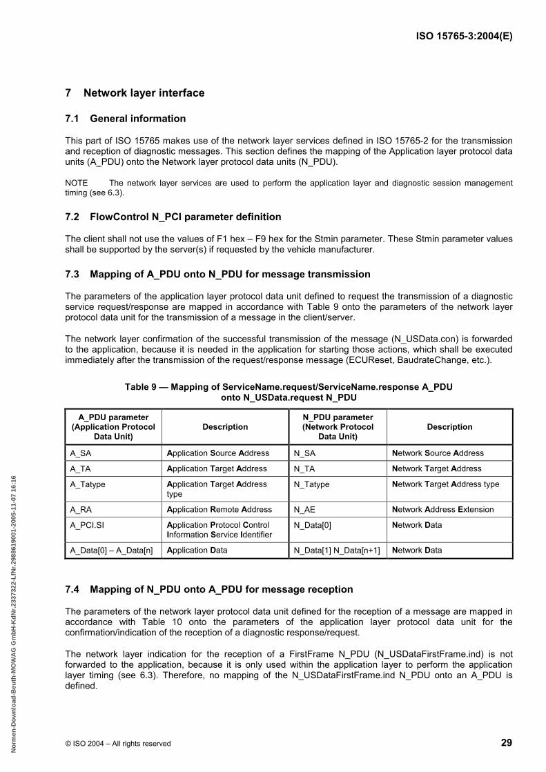
ISO 15765-3:2004(E)
© ISO 2004 – All rights reserved 29
7 Network layer interface
7.1 General information
This part of ISO 15765 makes use of the network layer services defined in ISO 15765-2 for the transmission and reception of diagnostic messages. This section defines the mapping of the Application layer protocol data units (A_PDU) onto the Network layer protocol data units (N_PDU).
NOTE The network layer services are used to perform the application layer and diagnostic session management timing (see 6.3).
7.2 FlowControl N_PCI parameter definition
The client shall not use the values of F1 hex – F9 hex for the Stmin parameter. These Stmin parameter values shall be supported by the server(s) if requested by the vehicle manufacturer.
7.3 Mapping of A_PDU onto N_PDU for message transmission
The parameters of the application layer protocol data unit defined to request the transmission of a diagnostic service request/response are mapped in accordance with Table 9 onto the parameters of the network layer protocol data unit for the transmission of a message in the client/server.
The network layer confirmation of the successful transmission of the message (N_USData.con) is forwarded to the application, because it is needed in the application for starting those actions, which shall be executed immediately after the transmission of the request/response message (ECUReset, BaudrateChange, etc.).
Table 9 — Mapping of ServiceName.request/ServiceName.response A_PDU onto N_USData.request N_PDU
A_PDU parameter (Application Protocol
Data Unit) Description
N_PDU parameter (Network Protocol
Data Unit) Description
A_SA Application Source Address N_SA Network Source Address
A_TA Application Target Address N_TA Network Target Address
A_Tatype Application Target Address type
N_Tatype Network Target Address type
A_RA Application Remote Address N_AE Network Address Extension
A_PCI.SI Application Protocol Control Information Service Identifier
N_Data[0] Network Data
A_Data[0] – A_Data[n] Application Data N_Data[1] N_Data[n+1] Network Data
7.4 Mapping of N_PDU onto A_PDU for message reception
The parameters of the network layer protocol data unit defined for the reception of a message are mapped in accordance with Table 10 onto the parameters of the application layer protocol data unit for the confirmation/indication of the reception of a diagnostic response/request.
The network layer indication for the reception of a FirstFrame N_PDU (N_USDataFirstFrame.ind) is not forwarded to the application, because it is only used within the application layer to perform the application layer timing (see 6.3). Therefore, no mapping of the N_USDataFirstFrame.ind N_PDU onto an A_PDU is defined.
B55EB1B3C7662F79D1B59483A53B9F2F82C98BEEB7939EA95CF14FFEE5FB13B925D84A2690B319CCC3FB33EC1A0EE19ACE32C3AD48AA2003E27076E26B823E886461F4EB146348E75A2E06040CBB18
No
rmen
-Do
wn
load
-Beu
th-M
OW
AG
Gm
bH
-Kd
Nr.
2337
322-
LfN
r.29
8861
9001
-200
5-11
-07
16:1
6

ISO 15765-3:2004(E)
30 © ISO 2004 – All rights reserved
Table 10 — Mapping of N_USData.ind N_PDU onto ServiceName.conf/ServiceName.ind A_PDU
N_PDU parameter (Network Protocol
Data Unit) Description
A_PDU parameter (Application Protocol
Data Unit) Description
N_SA Network Source Address A_SA Application Source Address
N_TA Network Target Address A_TA Application Target Address
N_TAtype Network Target Address type A_TAtype Application Target Address type
N_AE Network Address Extension A_RA Application Remote Address
N_Data[0] Network Data A_PCI.SI Application Protocol Control Information Service Identifier
N_Data[1] N_Data[n+1] Network Data A_Data[0] - A_Data[n] Application Data
8 Standardized diagnostic CAN identifiers
8.1 Legislated 11 bit OBD CAN identifiers
The 11 bit CAN identifiers for legislated OBD can also be used for enhanced diagnostics (e.g. the functional request CAN Id can be used for the functionally addressed TesterPresent (3E hex) request message to keep a non-defaultSession active).
If the 11 bit CAN Identifiers as specified in ISO 15765-4 are re-used for enhanced diagnostics, then the following requirements apply:
a) network layer timing parameters according ISO 15765-4 shall also apply for enhanced diagnostics;
b) the DLC (CAN data length code) shall be set to eight (8) and the CAN frame shall include eight (8) bytes (unused bytes shall be padded).
NOTE ISO 15765-4 allows for max. 8 OBD related servers (ECUs); therefore, 11 bit CAN identifiers for max. 8 servers are defined.
8.2 Legislated 29 bit OBD CAN identifiers
The 29 bit CAN identifiers for legislated OBD comply with the Normal fixed addressing format specified in ISO 15765-2 and can also be used for enhanced diagnostics.
If the 29 bit CAN Identifiers as specified in ISO 15765-4 are re-used for enhanced diagnostics, then the following requirements apply:
a) network layer timing parameters as specified in ISO 15765-4 shall also apply for enhanced diagnostics;
b) the DLC shall be set to eight (8) and the CAN frame shall include eight (8) bytes (unused bytes shall be padded).
NOTE The CAN identifier values given in the tables use the default value for the priority information in accordance with ISO 15765-2.
8.3 Enhanced diagnostics 29 bit CAN identifiers
8.3.1 General information
This section specifies a standardized addressing and routing concept for CAN using 29 bit identifiers. The concept makes use of the well-known and approved mechanisms of the internet protocol (IP). By this means,
B55EB1B3C7662F79D1B59483A53B9F2F82C98BEEB7939EA95CF14FFEE5FB13B925D84A2690B319CCC3FB33EC1A0EE19ACE32C3AD48AA2003E27076E26B823E886461F4EB146348E75A2E06040CBB18
No
rmen
-Do
wn
load
-Beu
th-M
OW
AG
Gm
bH
-Kd
Nr.
2337
322-
LfN
r.29
8861
9001
-200
5-11
-07
16:1
6

ISO 15765-3:2004(E)
© ISO 2004 – All rights reserved 31
standardized algorithms for addressing and routing can be used for all nodes in the whole network independent of their positioning in subnetworks.
This addressing and routing concept provides the following features:
maximum flexibility during the design process of network structures,
full customization of network and node address,
the possibility of CAN controller hardware filter feature optimization by the assignment of the appropriate network and node address,
gateways need to know only network addresses of the connected sub-networks instead of all addresses of their sub-network members.
The following specifies the technical details of the CAN identifier structure, the structure of addresses, and subnet masks. A detailed description of the algorithms used for routing and broadcasting is also included.
8.3.2 Structure of 29 bit CAN identifier
The 29 bit CAN identifier structure specified in this document is compatible in regard to coexistence with the definitions in ISO 15765-2, ISO 15765-3 and ISO 15765-4 and with SAE J1939-21. Therefore, the encoding of bit 25 (Reserved/Extended Data Page) and bit 24 (Data Page) in the 29 bit CAN identifier structure defined in SAE J1939-21 shall be used to determine whether a CAN identifier and frame is of SAE J1939 or ISO 15765 format. This enables the vehicle network designer to define non-diagnostic messages and associated CAN identifiers customized according to his needs or to utilize and benefit from the definitions in SAE J1939 in combination with a diagnostic services implementation as defined in ISO 15765-2, ISO 15765-3 and ISO 15765-4.
8.3.2.1 Structure of SAE J1939 29 bit CAN identifier
For information about the structure of the SAE J1939 29 bit CAN identifier format, see Table 11.
Table 11 — SAE J1939 structure of 29 bit CAN identifiers
29 bit CAN identifier
28 27 26 25 24 23 16 15 8 7 0
Priority Reserved/ Extended data page
Data page PDU Format
PDU-specific (destination or PDU format
extension)
Source address (unique source address)
8.3.2.2 Structure of ISO 15765 29 bit CAN identifier
Table 12 shows the structure of ISO 15765 CAN identifier that can be distinguished from the SAE J1939 format through the “SAE J1939 Reserved/Extended Data Page and ISO 15765 Extended Data Page” bit 25 and the “SAE J1939 Data Page ISO 15765 Data Page” bit 24. Thus, ISO 15765-formatted and SAE J1939-formatted 29 bit CAN identifiers can coexist on the same physical CAN bus system without interference.
Table 12 — ISO 15765 structure of 29 bit CAN identifiers
29 bit CAN identifier
28 27 26 25 24 23 22 21 11 10 0
Priority Extended data page
Data page
Type of service (TOS) Source address Destination address
Encoding see 8.3.2.4
Encoding see 8.3.2.5
Unique source address, see 8.3.3
Unique destination address, see 8.3.3
B55EB1B3C7662F79D1B59483A53B9F2F82C98BEEB7939EA95CF14FFEE5FB13B925D84A2690B319CCC3FB33EC1A0EE19ACE32C3AD48AA2003E27076E26B823E886461F4EB146348E75A2E06040CBB18
No
rmen
-Do
wn
load
-Beu
th-M
OW
AG
Gm
bH
-Kd
Nr.
2337
322-
LfN
r.29
8861
9001
-200
5-11
-07
16:1
6

ISO 15765-3:2004(E)
32 © ISO 2004 – All rights reserved
8.3.2.3 Priority field
The priority field is defined as specified in SAE J1939, to make use of the arbitration mechanism of CAN. Because the CAN identifier can no longer be assigned freely (source and target address are included in CAN identifier), the priority of a CAN message would be assigned by the sender (source address) and the receiver (target address) of that message indirectly. Eight (8) different priority levels are possible.
Priority level 6 (110b) shall be assigned to diagnostic request messages/frames.
8.3.2.4 Extended Data Page and Data Page field
The Extended Data Page and Data Page bits determine which format of the 29 bit CAN identifier shall be used. Table 13 specifies the encoding.
Table 13 — Definition of Extended Data Page and Data Page field
Extended data page bit 25 Data page bit 24 Description
0 0 SAE J1939-defined or manufacturer-defined “Normal Communication Message” strategy if SAE J1939 is not implemented
0 1 SAE J1939-defined or manufacturer-defined “Normal Communication Message” strategy if SAE J1939 is not implemented
1 0 SAE J1939-reserved or manufacturer-defined “Normal Communication Message” strategy if SAE J1939 is not implemented
1 1 ISO 15765-3-defined
8.3.2.5 Type of service (TOS) field
The type of service field is used to be able to address different services of a node without having to assign different addresses to it. Thus, eight (8) different service types of a node can be addressed concurrently using a single destination address. The different types of services and their usage are defined in Table 14.
Table 14 — Definition of Types Of Service (TOS)
Bit 23 Bit 22 Type Of Service (TOS) Description
0 0 ISO reserved This bit combination is reserved for future use by ISO.
0 1 OEM-defined messages This bit combination indicates that the messages are OEM-specific. A combination of ISO 15765-3 and legacy protocol messages can be used to support a mixture of servers on the same network with different protocol messages.
1 0 Network control message
protocol / network management
This bit combination indicates that the frame(s) contain data sent and received by gateways to supply information about the current state of subnets (e.g. network unreachable, network overload) and nodes (e.g. host unreachable).
1 1 ISO 15765-3-defined messages
This bit combination indicates an ISO 15765-3-defined diagnostic service addressed to a node. The user data bytes of the CAN frame contain diagnostic requests (ISO 15765-3) using the network layer services and transport layer defined in ISO 15765-2.
8.3.2.6 Source address
The source address contains the address of the sending entity. This information ensures the correct arbitration and can be used by the receiver of a message to address its replies. The structure of the source address is described in 8.3.3.
B55EB1B3C7662F79D1B59483A53B9F2F82C98BEEB7939EA95CF14FFEE5FB13B925D84A2690B319CCC3FB33EC1A0EE19ACE32C3AD48AA2003E27076E26B823E886461F4EB146348E75A2E06040CBB18
No
rmen
-Do
wn
load
-Beu
th-M
OW
AG
Gm
bH
-Kd
Nr.
2337
322-
LfN
r.29
8861
9001
-200
5-11
-07
16:1
6

ISO 15765-3:2004(E)
© ISO 2004 – All rights reserved 33
8.3.2.7 Destination address
The destination address contains the address of the receiving entity. This can be a single node, the broadcast address of a network or a generic broadcast. The destination address is used by gateways to determine whether the CAN frame shall be routed to another CAN bus or not. The structure of the target address is described in 8.3.3.
8.3.3 Structure of address
8.3.3.1 General information
The source and destination addresses are encoded in the 29 bit CAN identifier with a length of 11 bits each. In the following subclauses, the letters “X” and “Y” are used to represent a variable parameter.
8.3.3.2 Definition of address
An address consists of two parts.
a) Network address
The network address part consists of the first “X” sequential bits of the address and determines a node's network. The same network address shall be assigned to the nodes on one physical bus. The network address part shall not have all bits set to one (1). Thus, the minimum length for the network address part is two (2) bits. The maximum length is nine (9) bits because at least two (2) bits are needed to provide valid node address parts. The maximum number of possible subnets can be calculated as follows:
2X − 1 (where X is the number of bits used for the network address part)
b) Node address
The node address part consists of the remaining “Y” (Y = 11 – X) sequential bits of the address and determines the node within a subnet. It shall be unique within the subnet. All bits set to zero (0) and all bits set to one (1) are not allowed. Thus, the minimum length of the node address part is two (2) bits. The maximum length is nine (9) bits because at least two (2) bits are needed for the network address part. The maximum number of nodes per sub-network can be calculated as follows:
2Y − 2 (where Y is the number of bits used for the node address part)
A node is assigned a unique address that shall be stored in the node’s internal memory. A node shall receive messages with the node’s assigned address in the destination address field.
Table 15 presents an example for source and destination addresses. The sending and the receiving nodes are on different sub-networks.
Table 15 — Example for source and destination address
29 bit CAN identifier
28 27 26 25 24 23 22 21 11 10 0
Priority 0x6
ISO 15765 format
Type of service ISO 15765-3 messages
Source address 0x2ED
Destination address 0x32F
1 1 0 1 1 1 1 0 1 0 1 1 1 0 1 1 0 1 0 1 1 0 0 1 0 1 1 1 1
B55EB1B3C7662F79D1B59483A53B9F2F82C98BEEB7939EA95CF14FFEE5FB13B925D84A2690B319CCC3FB33EC1A0EE19ACE32C3AD48AA2003E27076E26B823E886461F4EB146348E75A2E06040CBB18
No
rmen
-Do
wn
load
-Beu
th-M
OW
AG
Gm
bH
-Kd
Nr.
2337
322-
LfN
r.29
8861
9001
-200
5-11
-07
16:1
6

ISO 15765-3:2004(E)
34 © ISO 2004 – All rights reserved
8.3.3.3 Subnet mask
The subnet mask assigns the number of bits used for the network address part and for the node address part.
The length of the subnet mask is 11 bits (same as the length of the address). The value of a subnet mask is assigned by setting the first “X” sequential bits set to one (1). The number of sequential bits set to one (1) selects the network address part from the whole address. The remaining sequential bits set to zero (0) select the node address part from the whole address (see Table 16 and Table 17 for examples of subnet masks for sender and receiver).
Due to the fixed length of a subnet mask and the first “X” sequential bits set to one (1), only the number of bits set to one (1) needs to be stored instead of the whole bit mask. Thus, a short notation is used to define a subnet mask.
Table 16 — Example for sender’s subnet mask
Subnet mask
10 9 8 7 6 5 4 3 2 1 0
0x7C0 (short notation: /5)
Network address part Node address part
1 1 1 1 1 0 0 0 0 0 0
Table 17 — Example for receiver’s subnet mask
Subnet mask
10 9 8 7 6 5 4 3 2 1 0
0x7E0 (short notation: /6)
Network address part Node address part
1 1 1 1 1 1 0 0 0 0 0
Each node is assigned a subnet mask that shall be stored in its internal memory. Nodes of the same subnet are assigned the same subnet mask.
8.3.3.4 Network address
The network address of a node can now be calculated using its assigned address and subnet mask. Therefore, a simple bit by bit AND operation of address and subnet mask shall be performed. See Tables 18 and 19 for examples of determining the network address of sender and receiver.
Table 18 — Example for sender’s network address
Source address
Bit 10 9 8 7 6 5 4 3 2 1 0
Address: 0x2ED 0 1 0 1 1 1 0 1 1 0 1
Subnet mask: /5 1 1 1 1 1 0 0 0 0 0 0
Network address: 0x2C0 0 1 0 1 1 0 0 0 0 0 0
B55EB1B3C7662F79D1B59483A53B9F2F82C98BEEB7939EA95CF14FFEE5FB13B925D84A2690B319CCC3FB33EC1A0EE19ACE32C3AD48AA2003E27076E26B823E886461F4EB146348E75A2E06040CBB18
No
rmen
-Do
wn
load
-Beu
th-M
OW
AG
Gm
bH
-Kd
Nr.
2337
322-
LfN
r.29
8861
9001
-200
5-11
-07
16:1
6

ISO 15765-3:2004(E)
© ISO 2004 – All rights reserved 35
Table 19 — Example for receiver’s network address
Destination address
Bit 10 9 8 7 6 5 4 3 2 1 0
Address 0x32F 0 1 1 0 0 1 0 1 1 1 1
Subnet mask: /6 1 1 1 1 1 1 0 0 0 0 0
Network address: 0x320 0 1 1 0 0 1 0 0 0 0 0
To describe a subnet, its network address and subnet mask are noted in the following form:
<network address> / <short subnet mask notation>
For the given examples this results in
sender’s subnet: 0x2C0 / 5
receiver’s subnet: 0x320 / 6
This information is used by gateways for routing.
8.3.3.5 Broadcast address
8.3.3.5.1 Generic broadcast (0x7FF)
The generic broadcast allows for broadcasting messages to all nodes of a network. To send a broadcast to the whole network, the target address 0x7FF [all bits set to one (1)] shall be used. A message with that target address will be routed by all gateways. All nodes on the network shall receive and process messages with destination address 0x7FF.
8.3.3.5.2 Subnet broadcast
The subnet broadcast is intended to be used for broadcasting messages to the nodes of a specific sub-network. To send a broadcast to a specific subnet, the broadcast address of that subnet shall be calculated. This is done by taking the destination's subnet information (network address and subnet mask) and setting all node address part bits [marked with zero (0) in subnet mask] to one (1). See Table 20 for a subnet broadcast example for the receiver’s subnet.
Table 20 — Example for subnet broadcast to receiver’s network
Destination address
Bit 10 9 8 7 6 5 4 3 2 1 0
Network address: 0x320 0 1 1 0 0 1 0 0 0 0 0
Subnet mask: /6 1 1 1 1 1 1 0 0 0 0 0
Broadcast address: 0x33F 0 1 1 0 0 1 1 1 1 1 1
Subnet broadcast messages are normally routed by gateways.
All nodes have to receive messages with the network address part equal to their own network address part and all bits set to “1” in the node address part of the destination address field.
8.3.4 Message retrieval
Each node on a subnet compares the destination address of a CAN frame with its own address. If those match, the information contained is transferred to the next higher layer in the OSI model for further processing.
B55EB1B3C7662F79D1B59483A53B9F2F82C98BEEB7939EA95CF14FFEE5FB13B925D84A2690B319CCC3FB33EC1A0EE19ACE32C3AD48AA2003E27076E26B823E886461F4EB146348E75A2E06040CBB18
No
rmen
-Do
wn
load
-Beu
th-M
OW
AG
Gm
bH
-Kd
Nr.
2337
322-
LfN
r.29
8861
9001
-200
5-11
-07
16:1
6

ISO 15765-3:2004(E)
36 © ISO 2004 – All rights reserved
8.3.5 Routing
8.3.5.1 General information
Routing applies whenever nodes from physically disconnected subnets communicate with each other and their CAN frames have to be transferred from one subnet to another subnet. This is performed by additional nodes, which are physically connected to the network where the CAN frame is received and the network where the CAN frame shall be transmitted to, to reach its destination. Thus, a CAN frame may pass several gateways from its source subnet to its destination.
8.3.5.2 Network and subnet structure
Generally, networks can be designed as needed when the following restrictions are respected:
addresses shall be unique;
all nodes in a subnet have the same subnet mask;
all nodes in a subnet have the same network address;
whenever a network address is assigned to a subnet, no further network addresses in that address scope may be assigned to other networks, as this would result in a routing problem.
Figure 13 shows a configuration with four (4) subnets connected to a gateway. Three (3) subnets are connected through one gateway and the 4th subnet is connected through an additional gateway.
Figure 13 — Network configuration example
B55EB1B3C7662F79D1B59483A53B9F2F82C98BEEB7939EA95CF14FFEE5FB13B925D84A2690B319CCC3FB33EC1A0EE19ACE32C3AD48AA2003E27076E26B823E886461F4EB146348E75A2E06040CBB18
No
rmen
-Do
wn
load
-Beu
th-M
OW
AG
Gm
bH
-Kd
Nr.
2337
322-
LfN
r.29
8861
9001
-200
5-11
-07
16:1
6

ISO 15765-3:2004(E)
© ISO 2004 – All rights reserved 37
8.3.5.3 Gateways and routing
8.3.5.3.1 Description
Gateways are nodes connected to more than one subnet and therefore able to transfer CAN frames from one subnet to another.
8.3.5.3.2 Ports
A port is the connection of a gateway to one physical subnet. A gateway shall have at least two (2) ports. Each port is assigned a network address and subnet mask of the subnet it is connected to.
In Figure 13, the configuration includes two (2) gateways, where gateway 1 has three ports and gateway 2 has two ports.
8.3.5.3.3 Routing table
To determine whether a CAN frame needs to be routed, a routing table shall be generated and stored in the gateway’s memory. A routing entry contains the network address, subnet mask and the port on which the subnet can be reached. Such an entry shall exist for each subnet that is connected (directly or indirectly) through this gateway.
See Table 21 for the network shown in Figure 13. Through hierarchical design of the networks 640/6 and 650/6, the routing table entries can be reduced to one entry 640/5.
Table 21 — Routing table example
subnet (network address/subnet mask) port
Gateway 1 500/5 1 680/6 2 640/5 3
Gateway 2
500/5 1 680/6 1 650/6 1 640/6 2
8.3.5.3.4 Routing algorithm
A gateway receives all messages from the ports that are connected to the different subnets. If the gateway is an addressable node, then only one address out of the address scopes of the subnets connected directly to the ports of that gateway shall be assigned. An additional message retrieval check is performed before the proper routing algorithm. If the destination address is 0x7FF, the message is copied to all ports except the one on which the message was received. The normal routing algorithm is skipped.
After having received Message A, the routing steps shall be as shown in Figure 14.
8.3.5.3.5 Routing example
In Figure 15, a routing example is shown for a CAN message from the client with the address 0x51A to the server with the address 0x642 using the routing information from Table 21.
B55EB1B3C7662F79D1B59483A53B9F2F82C98BEEB7939EA95CF14FFEE5FB13B925D84A2690B319CCC3FB33EC1A0EE19ACE32C3AD48AA2003E27076E26B823E886461F4EB146348E75A2E06040CBB18
No
rmen
-Do
wn
load
-Beu
th-M
OW
AG
Gm
bH
-Kd
Nr.
2337
322-
LfN
r.29
8861
9001
-200
5-11
-07
16:1
6

ISO 15765-3:2004(E)
38 © ISO 2004 – All rights reserved
The following steps are performed by the gateways on reception of that message.
a) Gateway 1
1) Analysis of CAN-ID: DA = 0x642. See Tables 22 and 23.
Table 22 — Gateway 1 routing decision
Routing decision Network Port
(0x642 AND 0x7C0) = 0x640 != 500 → no local message → routing 500/5 1
Table 23 — Gateway 1 routing analysis
Routing analysis Network Port
0x642 AND 0x7E0 = 0x640 != 680 → next entry 680/6 2
0x642 AND 0x7C0 = 0x640 = 640 → correct path 640/5 3
2) Check of whether the message is addressed to gateway: 0x642 != 0x654.
3) Forwarding of message to port 3.
b) Gateway 2
1) Analysis of CAN-ID: DA = 0x642. See Tables 24 and 25.
Table 24 — Gateway 2 routing decision
Routing decision Network Port
0x642 AND 0x7C0 = 0x640 != 650 → no local message → routing 650/6 1
Table 25 — Gateway 2 routing analysis
Routing analysis Network Port
0x642 AND 0x7E0 = 0x640 = 640 → correct path 640/6 2
2) check whether the message is addressed to gateway: 0x642 != 0x641.
3) forward message to port 2.
B55EB1B3C7662F79D1B59483A53B9F2F82C98BEEB7939EA95CF14FFEE5FB13B925D84A2690B319CCC3FB33EC1A0EE19ACE32C3AD48AA2003E27076E26B823E886461F4EB146348E75A2E06040CBB18
No
rmen
-Do
wn
load
-Beu
th-M
OW
AG
Gm
bH
-Kd
Nr.
2337
322-
LfN
r.29
8861
9001
-200
5-11
-07
16:1
6

ISO 15765-3:2004(E)
© ISO 2004 – All rights reserved 39
Steps A Message received on port “X”.
1 Bit by bit logical AND operation is performed with destination address of the received message and subnet mask of the port on which the message was received.
2 The result is compared with the network address of the port on which the message was received. The network address of the port is either stored in the node’s memory or can be calculated using the address and subnet mask of that port. If the result and the network address are equal, the received message is a local message of the port’s subnet and no routing will apply (B). If the result and the port’s network address are different, a routing analysis shall be performed, continuing with step 3.
3 A bit by bit logical AND operation is performed with destination address of the received message and the subnet mask of the current routing table entry.
4 The result of the operation and the network address of the current routing table entry are compared. If those matches the algorithm will continue with step 8, otherwise the algorithm will continue with step 5.
5 If there are additional routing table entries, the algorithm will continue with step 6. Otherwise no routing will apply (B).
6 The next routing table entry is selected and the algorithm jumps back to step 3.
7 The destination address of the message is compared with the gateway’s address on the current port. This step is only needed if the gateway is an addressable node, otherwise the algorithm jumps directly to step 8. If the destination address is the address of the gateway for the current port, the algorithm continues with step 9. If destination address and address of the gateway are not equal, the algorithm is continued at step 8.
8 The message is sent on the port of the routing table entry that matched the network address of the destination address.
9 The message was addressed to gateway node and thus, it is processed by application.
B End of routing algorithm.
B55EB1B3C7662F79D1B59483A53B9F2F82C98BEEB7939EA95CF14FFEE5FB13B925D84A2690B319CCC3FB33EC1A0EE19ACE32C3AD48AA2003E27076E26B823E886461F4EB146348E75A2E06040CBB18
No
rmen
-Do
wn
load
-Beu
th-M
OW
AG
Gm
bH
-Kd
Nr.
2337
322-
LfN
r.29
8861
9001
-200
5-11
-07
16:1
6

ISO 15765-3:2004(E)
40 © ISO 2004 – All rights reserved
Key DA destination address GWAD gateway's address on port_X NA network address SM subnet mask entry_X entry #X in the gateway's routing table port_X port #X of the gateway
Figure 14 — Routing algorithm sequence chart
Key virtual connection
message path on CAN bus
message path in gateway
Figure 15 — Routing example from client 0x51A to server 0x642
9 Diagnostic services implementation
9.1 Unified diagnostic services overview
This clause defines how the diagnostic services as defined in ISO 14229-1 apply to CAN. For each applicable service, the applicable subfunction and data parameters are defined.
NOTE The subfunction parameter definitions take into account that the most significant bit is used for the suppressPosRspMsgIndicationBit parameter as defined in ISO 14229-1.
B55EB1B3C7662F79D1B59483A53B9F2F82C98BEEB7939EA95CF14FFEE5FB13B925D84A2690B319CCC3FB33EC1A0EE19ACE32C3AD48AA2003E27076E26B823E886461F4EB146348E75A2E06040CBB18
No
rmen
-Do
wn
load
-Beu
th-M
OW
AG
Gm
bH
-Kd
Nr.
2337
322-
LfN
r.29
8861
9001
-200
5-11
-07
16:1
6

ISO 15765-3:2004(E)
© ISO 2004 – All rights reserved 41
The purpose of Table 26 is to provide an overview of all unified diagnostic services, as they are applicable for an implementation of diagnostics on CAN. The table contains the sum of all applicable services. Certain applications using this part of ISO 15765 to implement diagnostics on CAN may restrict the number of useable services and may categorize them in certain application areas/diagnostic sessions (default session, programming session, etc.).
Table 26 — Diagnostics on CAN -– Unified diagnostic services overview
Diagnostic service name (ISO 14229-1)
Service Id value (hex)
Subfunction supported
suppressPosRspMsgIndicationBit = TRUE (1)
(No response) supported a
Subclause
Diagnostic and Communication Management Functional Unit
DiagnosticSessionControl 10 Yes Yes 9.2.1
ECUReset 11 Yes Yes 9.2.2
SecurityAccess 27 Yes Yes 9.2.3
CommunicationControl 28 Yes Yes 9.2.4
TesterPresent 3E Yes Yes 9.2.5
SecuredDataTransmission 84 — N/A 9.2.6
ControlDTCSetting 85 Yes Yes 9.2.7
ResponseOnEvent 86 Yes Yes 9.2.8
LinkControl 87 Yes Yes 9.2.9
Data Transmission Functional Unit
ReadDataByIdentifier 22 — N/A 9.3.1
ReadMemoryByAddress 23 — N/A 9.3.2
ReadScalingDataByIdentifier 24 — N/A 9.3.3
ReadDataByPeriodicIdentifier 2A — N/A 9.3.4
DynamicallyDefineDataIdentifier 2C Yes Yes 9.3.5
WriteDataByIdentifier 2E — N/A 9.3.6
WriteMemoryByAddress 3D — N/A 9.3.7
Stored Data Transmission Functional Unit
ReadDTCInformation 19 Yes Yes 9.4.1
ClearDiagnosticInformation 14 — N/A 9.4.2
Input/Output Control Functional Unit
InputOutputControlByidentifier 2F — N/A 9.5.1
Remote Activation Of Routine Functional Unit
RoutineControl 31 Yes yes 9.6.1
Upload/Download Functional Unit
RequestDownload 34 — N/A 9.7.1
RequestUpload 35 — N/A 9.7.2
TransferData 36 — N/A 9.7.3
RequestTransferExit 37 — N/A 9.7.4
a It is implied that suppressPosRspMsgIndicationBit = FALSE (0) is supported by each service that utilizes a subfunction parameter. It is the system designer's responsibility to assure that in case the client does not require a response message [suppressPosRspMsgIndicationBit = TRUE (1)] and the server might need more than P2CAN_Server to process the request message that the client shall insert sufficient time between subsequent requests. There might be situations where a server is not able to perform the requested action nor being able to indicate the reason to the client.
B55EB1B3C7662F79D1B59483A53B9F2F82C98BEEB7939EA95CF14FFEE5FB13B925D84A2690B319CCC3FB33EC1A0EE19ACE32C3AD48AA2003E27076E26B823E886461F4EB146348E75A2E06040CBB18
No
rmen
-Do
wn
load
-Beu
th-M
OW
AG
Gm
bH
-Kd
Nr.
2337
322-
LfN
r.29
8861
9001
-200
5-11
-07
16:1
6

ISO 15765-3:2004(E)
42 © ISO 2004 – All rights reserved
9.2 Diagnostic and communication control functional unit
9.2.1 DiagnosticSessionControl (10 hex) service
Table 27 defines the subfunction parameters applicable for the implementation of this service on CAN.
Table 27 — Subfunction parameter definition
Hex (bit 6-0)
Description Cvt Mnemonic
01 defaultSession U DS
02 ECUProgrammingSession U ECUPS
03 ECUExtendedDiagnosticSession U ECUEDS
Tables 28 and 29 define the structure of the response message data parameter sessionParameterRecord as applicable for the implementation of this service on CAN.
Table 28 — sessionParameterRecord definition
Byte pos. in record
Description Cvt Hex Value Mnemonic
#1 #2 #3 #4
sessionParameterRecord[] #1 = [ P2CAN_Server_max (high byte) P2CAN_Server_max (low byte) P2*CAN_Server_max (high byte) P2*CAN_Server_max (low byte) ]
M M M M
00-FF 00-FF 00-FF 00-FF
SPREC_ P2CSMH P2CSML
P2ECSMH P2ECSML
Table 29 — sessionParameterRecord content definition
Parameter Description # of bytes Resolution min value max value
P2CAN_Server_max Default P2CAN_Server_max timing supported by the server for the activated diagnostic session.
2 1 ms 0 ms 65535 ms
P2*CAN_Server_max Enhanced (NRC 78 hex) P2CAN_Server_max supported by the server for the activated diagnostic session.
2 10 ms 0 ms 655350 ms
9.2.2 ECUReset (11 hex) service
Table 30 defines the subfunction parameters applicable for the implementation of this service on CAN.
Table 30 — Subfunction parameter definition
Hex (bit 6-0)
Description Cvt Mnemonic
01 hardReset U HR
02 keyOffOnReset U KOFFONR
03 softReset U SR
04 enableRapidPowerShutDown U ERPSD
05 disableRapidPowerShutDown U DRPSD
B55EB1B3C7662F79D1B59483A53B9F2F82C98BEEB7939EA95CF14FFEE5FB13B925D84A2690B319CCC3FB33EC1A0EE19ACE32C3AD48AA2003E27076E26B823E886461F4EB146348E75A2E06040CBB18
No
rmen
-Do
wn
load
-Beu
th-M
OW
AG
Gm
bH
-Kd
Nr.
2337
322-
LfN
r.29
8861
9001
-200
5-11
-07
16:1
6

ISO 15765-3:2004(E)
© ISO 2004 – All rights reserved 43
9.2.3 SecurityAccess (27 hex) service
Table 31 defines the subfunction parameters applicable for the implementation of this service on CAN.
Table 31 — Subfunction parameter definition
Hex (bit 6-0)
Description Cvt Mnemonic
01 requestSeed U RSD
02 sendKey U SK
03, 05, 07-5F
requestSeed U RSD
04, 06, 08-60
sendKey U SK
9.2.4 CommunicationControl (28 hex) service
Table 32 defines the subfunction parameters applicable for the implementation of this service on CAN.
Table 32 — Subfunction parameter definition
Hex (bit 6-0)
Description Cvt Mnemonic
00 enableRxAndTx U ERXTX
01 enableRxAndDisableTx U ERXDTX
02 disableRxAndEnableTx U DRXETX
03 disableRxAndTx U DRXTX
Table 33 defines the data parameters applicable for the implementation of this service on CAN.
Table 33 — Data parameter definition — CommunicationType
Bit 1-0 Description Cvt Mnemonic
01b application U APPL
10b networkManagement U NWM
Bit 1 – 0 can be used in any combination. Each bit represents a communicationType. More then one communicationType may be initialised at the same time.
9.2.5 TesterPresent (3E hex) service
Table 34 defines the subfunction parameters applicable for the implementation of this service on CAN.
Table 34 — Subfunction parameter definition
Hex (bit 6-0)
Description Cvt Mnemonic
00 zeroSubFunction M ZSUBF
B55EB1B3C7662F79D1B59483A53B9F2F82C98BEEB7939EA95CF14FFEE5FB13B925D84A2690B319CCC3FB33EC1A0EE19ACE32C3AD48AA2003E27076E26B823E886461F4EB146348E75A2E06040CBB18
No
rmen
-Do
wn
load
-Beu
th-M
OW
AG
Gm
bH
-Kd
Nr.
2337
322-
LfN
r.29
8861
9001
-200
5-11
-07
16:1
6

ISO 15765-3:2004(E)
44 © ISO 2004 – All rights reserved
9.2.6 SecuredDataTransmission (84 hex) service
There are neither additional requirements nor restrictions defined for this service for its implementation on CAN.
9.2.7 ControlDTCSetting (85 hex) service
Table 35 defines the subfunction parameters applicable for the implementation of this service on CAN.
Table 35 — Subfunction parameter definition
Hex (bit 6-0)
Description Cvt Mnemonic
01 on M ON
02 off M OFF
9.2.8 ResponseOnEvent (86 hex) service
The following requirements shall apply for this service when implemented on CAN.
a) Multiple ResponseOnEvent services may run concurrently with different requirements (different EventTypes, serviceToRespondTo-Records, ...) to start and stop diagnostic services.
b) While the ResponseOnEvent service is active, the server shall be able to process concurrent diagnostic request and response messages accordingly. This should be accomplished with a (different) pair of serviceToRespondTo-request/response CAN identifiers. See Figure 16. If the same diagnostic request/response CAN identifiers are used for diagnostic communication and the serviceToRespondTo-responses, the following restrictions shall apply.
1) The server shall ignore an incoming diagnostic request after an event has occurred and the serviceToRespondTo-response is in progress, until the serviceToRespondTo-response is completed.
2) After the client receives any response after sending a diagnostic request, the response shall be classified according to the possible serviceToRespondTo-responses and the expected diagnostic responses that have been sent.
3) If the response is a serviceToRespondTo-response (one of the possible responses set up with ResponseOnEvent-service), the client shall repeat the request after the serviceToRespondTo-response has been received completely.
4) If the response is ambiguous (i.e. the response could originate from the serviceToRespondTo initiated by an event or from the response to a diagnostic request), the client shall present the response both as a serviceToRespondTo-response and as the response to the diagnostic request. The client shall not repeat the request with the exception of NegativeResponseCode busyRepeatRequest (21 hex). (See the negative response code definitions in ISO 14229-1.)
c) The ResponseOnEvent service shall only be allowed to use those diagnostic services available in the active diagnostic session.
d) While the ResponseOnEvent service is active, any change in a diagnostic session shall terminate the current ResponseOnEvent service(s). For instance, if a ResponseOnEvent service has been set up during extendedDiagnosticSession, it shall terminate when the server switches to the defaultSession.
e) If a ResponseOnEvent (86 hex) service has been set up during defaultSession, then the following shall apply:
B55EB1B3C7662F79D1B59483A53B9F2F82C98BEEB7939EA95CF14FFEE5FB13B925D84A2690B319CCC3FB33EC1A0EE19ACE32C3AD48AA2003E27076E26B823E886461F4EB146348E75A2E06040CBB18
No
rmen
-Do
wn
load
-Beu
th-M
OW
AG
Gm
bH
-Kd
Nr.
2337
322-
LfN
r.29
8861
9001
-200
5-11
-07
16:1
6

ISO 15765-3:2004(E)
© ISO 2004 – All rights reserved 45
1) If Bit 6 of the eventType subfunction parameter is set to 0 (do not store event), then the event shall terminate when the server powers down The server shall not continue a ResponseOnEvent diagnostic service after a reset or power on (i.e. the ResponseOnEvent service is terminated).
2) If Bit 6 of the eventType subfunction parameter is set to 1 (store event), it shall resume sending serviceToRespondTo-responses according to the ResponseOnEvent-set up after a power cycle of the server.
Figure 16 — Concurrent request when the event occurs
f) The subfunction parameter value responseRequired = “no” should only be used for the eventType =
stopResponseOnEvent, startResponseOnEvent or clearResponseOnEvent The server shall always return a response to the event-triggered response when the specified event is detected.
g) The server shall return a final positive response to indicate the ResponseOnEvent (86 hex) service has reached the end of the finite event window, unless one of the following conditions apply:
1) if eventTypes do not setup ResponseOnEvent, such as stopResponseOnEvent, startResponseOnEvent, clearResponseOnEvent or reportActivatedEvents;
2) if the infinite event window was established
if the Service has been deactivated before the event window was closed,
Bit 6 of the eventType subfunction parameter is set to 0 (do not store) and the server powers down or resets.
h) When the specified event is detected, the server shall respond immediately with the appropriate serviceToRespondTo-response message. The immediate serviceToRespondTo-response message shall not disrupt any other diagnostic request or response transmission already in progress (i.e. the
B55EB1B3C7662F79D1B59483A53B9F2F82C98BEEB7939EA95CF14FFEE5FB13B925D84A2690B319CCC3FB33EC1A0EE19ACE32C3AD48AA2003E27076E26B823E886461F4EB146348E75A2E06040CBB18
No
rmen
-Do
wn
load
-Beu
th-M
OW
AG
Gm
bH
-Kd
Nr.
2337
322-
LfN
r.29
8861
9001
-200
5-11
-07
16:1
6

ISO 15765-3:2004(E)
46 © ISO 2004 – All rights reserved
serviceToRespondTo-response shall be delayed until the current message transmission has been completed — see Figure 17).
Figure 17 — Event occurrence during a message in progress
i) The ResponseOnEvent service shall only apply to transient events and conditions. The server shall return a response once per event occurrence. For a condition that is continuously sustained over a period of time, the response service shall be executed only one time at the initial occurrence. In case the eventType is defined so that serviceToRespondTo-responses could occur at a high frequency, then appropriate measures have to be taken in order to prevent back to back serviceToRespondTo-responses. A minimum separation time between serviceToRespondTo-responses could be part of the eventTypeRecord (vehicle-manufacturer-specific).
Tables 36 and 37 define the subfunction parameters applicable for the implementation of this service on CAN.
Table 38 defines the data parameters applicable for the implementation of this service on CAN.
Table 36 — eventType subfunction bit 6 definition — StorageState
Bit 6 value
Description Cvt Mnemonic
0 doNotStoreEvent M DNSE
1 storeEvent U SE
B55EB1B3C7662F79D1B59483A53B9F2F82C98BEEB7939EA95CF14FFEE5FB13B925D84A2690B319CCC3FB33EC1A0EE19ACE32C3AD48AA2003E27076E26B823E886461F4EB146348E75A2E06040CBB18
No
rmen
-Do
wn
load
-Beu
th-M
OW
AG
Gm
bH
-Kd
Nr.
2337
322-
LfN
r.29
8861
9001
-200
5-11
-07
16:1
6

ISO 15765-3:2004(E)
© ISO 2004 – All rights reserved 47
Table 37 — Subfunction parameter definition
Hex (bit 5-0)
Description Cvt Mnemonic
00 stopResponseOnEvent U STPROE
01 onDTCStatusChange U ONDTCS
02 onTimerInterrupt U OTI
03 onChangeOfDataIdentifier U OCOCID
04 reportActivatedEvents U RAE
05 startResponseOnEvent U STRTROE
06 clearResponseOnEvent U CLRROE
07 onComparisonOfValues M OCOV
Table 38 — Data parameter definition — serviceToRespondToRecord.serviceId
Recommended services (ServiceToRespondTo) RequestService Identifier (SId)
ReadDataByIdentifier 22 hex
ReadDTCInformation 19 hex
RoutineControl 31 hex
InputOutputControlByIdentifier 2F hex
9.2.9 LinkControl (87 hex) service
Table 39 defines the subfunction parameters applicable for the implementation of this service on CAN.
Table 39 — Subfunction parameter definition
Hex (bit 6-0)
Description Cvt Mnemonic
01 verifyBaudrateTransitionWithFixedBaudrate U VBTWFBR
02 verifyBaudrateTransitionWithSpecificBaudrate U VBTWSBR
03 transitionBaudrate U TB
9.3 Data transmission functional unit
9.3.1 ReadDataByIdentifier (22 hex) service
There are neither additional requirements nor restrictions defined for this service for its implementation on CAN.
9.3.2 ReadMemoryByAddress (23 hex) service
There are neither additional requirements nor restrictions defined for this service for its implementation on CAN.
B55EB1B3C7662F79D1B59483A53B9F2F82C98BEEB7939EA95CF14FFEE5FB13B925D84A2690B319CCC3FB33EC1A0EE19ACE32C3AD48AA2003E27076E26B823E886461F4EB146348E75A2E06040CBB18
No
rmen
-Do
wn
load
-Beu
th-M
OW
AG
Gm
bH
-Kd
Nr.
2337
322-
LfN
r.29
8861
9001
-200
5-11
-07
16:1
6

ISO 15765-3:2004(E)
48 © ISO 2004 – All rights reserved
9.3.3 ReadScalingDataByIdentifier(24 hex) service
There are neither additional requirements nor restrictions defined for this service for its implementation on CAN.
9.3.4 ReadDataByPeriodicIdentifier (2A hex) service
The two types of response messages as defined for this service in ISO 14229-1 are mapped onto CAN as follows.
Response message type #1 (including the service identifier, the echo of the periodicDataIdentifier and the data of the periodicDataIdentifier): This type of response message is mapped onto a USDT3) message, using the same response CAN identifier as used for any other USDT response message. The USDT message for a single periodicDataIdentifier shall not exceed the size of a single CAN frame, which means that the complete USDT response message shall fit into a SingleFrame N_PDU.
Response message type #2 (including the periodicDataIdentifier and the data of the periodicDataIdentifier): This type of response message is mapped onto a UUDT4) message, using a different CAN identifier as used for the USDT response message. The UUDT message for a single periodicDataIdentifier shall not exceed the size of a single CAN frame.
The mapping of the two response types lead to certain client and server requirements as listed in Tables 40 and 41.
Table 40 — Periodic transmission — Requirements for the response type #1 message mapping
Message type Client requestrequirements
Server response requirements
Further server restrictions
Any other new incoming request shall be prioritized and the periodic transmission may be delayed.
The periodic response is processed in the server as a regular USDT message (with protocol control information (PCI), service identifier (SId) and periodicDataIdentifier) and is processed by the server network layer. This means that a maximum of 5 data bytes are available for the data of a periodicDataIdentifier when using normal addressing and 4 data bytes when using extended addressing for the response message.
USDT
uses the same CAN identifier for
diagnostic communication and
periodic transmission
No restrictions
Only single-frame responses for
periodic transmission
Multi-frame responses to new
(non-periodic-transmission)
requests possible
For an incoming multi-frame request message, any scheduled periodic transmission shall be delayed in the server immediately after the N_USDataFF.ind of a multi-frame request or the N_USData.ind of a SingleFrame request is processed by the application. Once the complete service is processed (including the final response message), the transmission of the periodic messages shall be continued.
3) USDT Unacknowledged Segmented Data Transfer, ISO 15765-2 network layer, includes protocol control information for segmented data transmission.
4) UUDT Unacknowledged Unsegmented Data Transfer, single CAN frames, do not include protocol control information, which results in max. 7/8 data bytes for normal/extended addressing.
B55EB1B3C7662F79D1B59483A53B9F2F82C98BEEB7939EA95CF14FFEE5FB13B925D84A2690B319CCC3FB33EC1A0EE19ACE32C3AD48AA2003E27076E26B823E886461F4EB146348E75A2E06040CBB18
No
rmen
-Do
wn
load
-Beu
th-M
OW
AG
Gm
bH
-Kd
Nr.
2337
322-
LfN
r.29
8861
9001
-200
5-11
-07
16:1
6

ISO 15765-3:2004(E)
© ISO 2004 – All rights reserved 49
Table 41 — Periodic transmission — Requirements for response type #2 message mapping
Message type Client request requirements
Server response requirements
Further server restrictions
The request for periodic transmission is processed as a regular diagnostic request and the response is sent via the network layer (as a USDT message with service identifier 6A hex).
On receiving the N_USData.con that indicates the completion of the transmission of the positive response, the application starts an independent scheduler, which handles the periodic transmission.
The scheduler in the server processes the periodic transmission as a single frame UUDT-message in a by-pass (i.e. writes the UUDT message directly to the CAN-controller/data link layer driver without using the network-layer).
UUDT
uses a different CAN identifier for
periodic transmission
No restrictions
Only single-frame responses for
periodic transmission
Multi-frame responses to new
(non-periodic-transmission)
requests are possible For an UUDT-message there is no need to include protocol control information (PCI) and service identifier (SId), only the periodic identifier is included, so a maximum of 7 data bytes can be used for the data of a periodicDataIdentifier for normal addressing and 6 data bytes for extended addressing.
Figures 18 and 19 graphically depict the two types of periodic response messages, as the server should handle them. Furthermore, the figures show that the periodically transmitted response messages do not have any influence on the S3Server timer of the server. For both figures it is assumed that a non-defaultSession has been activated prior to the configuration of the periodic scheduler (the ReadDataByPeriodicIdentifier service requires a non-defaultSession in order to be executed).
B55EB1B3C7662F79D1B59483A53B9F2F82C98BEEB7939EA95CF14FFEE5FB13B925D84A2690B319CCC3FB33EC1A0EE19ACE32C3AD48AA2003E27076E26B823E886461F4EB146348E75A2E06040CBB18
No
rmen
-Do
wn
load
-Beu
th-M
OW
AG
Gm
bH
-Kd
Nr.
2337
322-
LfN
r.29
8861
9001
-200
5-11
-07
16:1
6

ISO 15765-3:2004(E)
50 © ISO 2004 – All rights reserved
B55EB1B3C7662F79D1B59483A53B9F2F82C98BEEB7939EA95CF14FFEE5FB13B925D84A2690B319CCC3FB33EC1A0EE19ACE32C3AD48AA2003E27076E26B823E886461F4EB146348E75A2E06040CBB18
No
rmen
-Do
wn
load
-Beu
th-M
OW
AG
Gm
bH
-Kd
Nr.
2337
322-
LfN
r.29
8861
9001
-200
5-11
-07
16:1
6

ISO 15765-3:2004(E)
© ISO 2004 – All rights reserved 51
a The diagnostic application of the client starts the transmission of the ReadDataByPeriodicIdentifier (2A hex) request message by issuing a N_USData.req to its network layer. The network layer transmits the ReadDataByPeriodicIdentifier (2A hex) request message to the server. The request message can either be a single-frame message or a multi-frame message (depends on the number of periodicDataIdentifier contained in the request message). For the example given, it is assumed that the request message is a SingleFrame message. b The completion of the request message is indicated in the client via N_USData.con. Now the response timing as described in 6.3.5.1.1 and 6.3.5.1.2 applies. c The completion of the request message is indicated in the server via the N_USData.ind. Now the response timing as described in 6.3.5.1.1 and 6.3.5.1.2 applies. Furthermore, the server stops its S3Server timer. d For the figure given, it is assumed that the client requires a response from the server. The server shall transmit the ReadDataByPeriodicIdentifier positive response message to indicate that the request has been processed and that the transmission of the periodic messages will start afterwards. e The completion of the transmission of the ReadDataByPeriodicIdentifier response message is indicated in the server via N_USData.con. Now the server restarts its S3Server timer, which keeps the activated non-default session active as long as it does not time out. f The server starts to transmit the periodic response messages (SingleFrame message). Each periodic message utilizes the network layer protocol and uses the response CAN identifier that is also used for any other response message. Therefore, the server issues a N_USData.req to the network layer each time a periodic message is transmitted and no other service is currently in the process of being handled by the server. For the example given, it is assumed that the server is able to transmit three (3) periodic messages prior to the next request message that is issued by the client. The transmission of the periodic response messages has no influence on the S3Server timer (see 6.3.5.4). g The diagnostic application of the client starts the transmission of the next request message by issuing a N_USData.req to its network layer. The network layer transmits the request message to the server. The request message can either be a single-frame message or a multi-frame message. For the example given, it is assumed that the request message is a multi-frame message. h The completion of the request message is indicated in the client via N_USData.con. Now the response timing as described in 6.3.5.1.1 and 6.3.5.1.2 applies. i Once the start of a request message is indicated in the server via N_USDataFF.ind (or N_USData.ind for SingleFrame request messages) while a periodic scheduler is active, the server shall temporarily stop the periodic scheduler for the duration of processing the received request message. Furthermore, any time the server is in the process of handling any diagnostic service it stops its S3Server timer. j The completion of the multi-frame request message is indicated in the server via the N_USData.ind. Now the response timing as described in 6.3.5.1.1 and 6.3.5.1.2 applies. The scheduler for the transmission of the periodic messages remains disabled. k For the figure given, it is assumed that the client requires a response from the server. The server shall transmit the positive (or negative) response message via issuing N_USData.req to its network layer. For the example, it is assumed that the response is a multi-frame message. l When the S3Client timer times out in the client, then the client transmits a functionally addressed TesterPresent (3E hex) request message to reset the S3Server timer in the server. m The server is in the process of transmitting the multi-frame response of the previous request. Therefore, the server shall not act on the received TesterPresent (3E hex) request message, because its S3Server timer is not yet re-activated. n When the diagnostic service is completely processed, then the server restarts its S3Server timer. This means that any diagnostic service, including TesterPresent (3E hex), resets the S3Server timer. A diagnostic service is meant to be in progress any time between the start of the reception of the request message (N_USDataFF.ind or N_USData.ind receive) and the completion of the transmission of the response message, where a response message is required, or the completion of any action that is caused by the request, where no response message is required (point in time reached that would cause the start of the response message). This includes negative response messages including response code 78 hex. The server re-enables the periodic scheduler when the service is completely processed (final response message completely transmitted). o The server restarts the transmission of the periodic response messages (SingleFrame message). Each periodic message utilizes the network layer protocol and uses the response CAN identifier that is also used for any other response message. Therefore, the server issues a N_USData.req to the network layer each time a periodic message is transmitted and no other service is currently in the process of being handled by the server. The transmission of the periodic response messages has no influence on the S3Server timer (see 6.3.5.4). p Once the S3Client timer is started in the client (non-defaultSession active), this causes the transmission of a functionally addressed TesterPresent (3E hex) request message, which does not require a response message, each time the S3Client timer times out. q Upon the indication of the completed transmission of the TesterPresent (3E hex) request message via N_USData.con of its network layer, the client once again starts its S3Client timer. This means that the functionally addressed TesterPresent (3E hex) request message is sent on a periodic basis every time S3Client times out.
Figure 18 — Response message type #1 handling
B55EB1B3C7662F79D1B59483A53B9F2F82C98BEEB7939EA95CF14FFEE5FB13B925D84A2690B319CCC3FB33EC1A0EE19ACE32C3AD48AA2003E27076E26B823E886461F4EB146348E75A2E06040CBB18
No
rmen
-Do
wn
load
-Beu
th-M
OW
AG
Gm
bH
-Kd
Nr.
2337
322-
LfN
r.29
8861
9001
-200
5-11
-07
16:1
6

ISO 15765-3:2004(E)
52 © ISO 2004 – All rights reserved
B55EB1B3C7662F79D1B59483A53B9F2F82C98BEEB7939EA95CF14FFEE5FB13B925D84A2690B319CCC3FB33EC1A0EE19ACE32C3AD48AA2003E27076E26B823E886461F4EB146348E75A2E06040CBB18
No
rmen
-Do
wn
load
-Beu
th-M
OW
AG
Gm
bH
-Kd
Nr.
2337
322-
LfN
r.29
8861
9001
-200
5-11
-07
16:1
6

ISO 15765-3:2004(E)
© ISO 2004 – All rights reserved 53
a The diagnostic application of the client starts the transmission of the ReadDataByPeriodicIdentifier (2A hex) request message by issuing a N_USData.req to its network layer. The network layer transmits the ReadDataByPeriodicIdentifier (2A hex) request message to the server. The request message can either be a single-frame or multi-frame message (depends on the number of periodicDataIdentifier contained in the request message). For the example given, it is assumed that the request message is a SingleFrame message. b The completion of the request message is indicated in the client via N_USData.con. Now the response timing as described in 6.3.5.1.1 and 6.3.5.1.2 applies. c The completion of the request message is indicated in the server via the N_USData.ind. Now the response timing as described in 6.3.5.1.1 and 6.3.5.1.2 applies. Furthermore, the server stops its S3Server timer. d It is assumed that the client requires a response from the server. The server shall transmit the ReadDataByPeriodicIdentifier positive response message to indicate that the request has been processed and that the transmission of the periodic messages will start afterwards. e The completion of the transmission of the ReadDataByPeriodicIdentifier response message is indicated in the server via N_USData.con. Now the server restarts its S3Server timer, which keeps the activated non-default session active as long as it does not time out. f The server starts to transmit the periodic response messages (single-frame message). Each periodic message is a UUDT message and uses a different CAN identifier as used for any other response message (USDT CAN identifier). Therefore, the server issues a N_UUData.req each time a periodic message is transmitted independent of any other service currently processed by the server. This means that the transmission of the periodic response messages continues even when the server is in the process of handling another diagnostic service request. The transmission of the periodic response messages has no influence on the S3Server timer (see 6.3.5.4). g The diagnostic application of the client starts the transmission of the next request message by issuing a N_USData.req to its network layer. The network layer transmits the request message to the server. The request message can either be a single-frame or multi-frame message. For the example given, it is assumed that the request message is a multi-frame message. h The completion of the request message is indicated in the client via N_USData.con. Now the response timing as described in 6.3.5.1.1 and 6.3.5.1.2 applies. i The start of a request message is indicated in the server via N_USDataFF.ind (or N_USData.ind for SingleFrame request messages) while a periodic scheduler is active. The server does not stop the periodic scheduler for the duration of processing the received request message. This means that the server transmits further periodic messages for the duration of processing the diagnostic service. The client shall be aware of receiving these periodic response messages. Furthermore, any time the server is in the process of handling any diagnostic service it stops its S3Server timer. j The completion of the multi-frame request message is indicated in the server via the N_USData.ind. Now the response timing as described in 6.3.5.1.1 and 6.3.5.1.2 applies. k For the figure given, it is assumed that the client requires a response from the server. The server shall transmit the positive (or negative) response message via issuing N_USData.req to its network layer. For the example, it is assumed that the response is a multi-frame message. While the multi-frame response message is transmitted by the network layer, the periodic scheduler continues to transmit the periodic response messages. l When the S3Client timer times out in the client, then the client transmits a functionally addressed TesterPresent (3E hex) request message to reset the S3Server timer in the server. m The server is in the process of transmitting the multi-frame response of the previous request. Therefore, the server shall not act on the received TesterPresent (3E hex) request message, because its S3Server timer is not yet re-activated. n When the diagnostic service is completely processed, then the server restarts its S3Server timer. This means that any diagnostic service, including TesterPresent (3E hex), resets the S3Server timer. A diagnostic service is meant to be in progress any time between the start of the reception of the request message (N_USDataFF.ind or N_USData.ind receive) and the completion of the transmission of the response message, where a response message is required, or the completion of any action that is caused by the request, where no response message is required (point in time reached that would cause the start of the response message). This includes negative response messages including response code 78 hex. o Once the S3Client timer is started in the client (non-defaultSession active), this causes the transmission of a functionally addressed TesterPresent (3E hex) request message, which does not require a response message, each time the S3Client timer times out. p Upon the indication of the completed transmission of the TesterPresent (3E hex) request message via N_USData.con of its network layer, the client once again starts its S3Client timer. This means that the functionally addressed TesterPresent (3E hex) request message is sent on a periodic basis every time S3Client times out.
Figure 19 — Response message type #2 handling
B55EB1B3C7662F79D1B59483A53B9F2F82C98BEEB7939EA95CF14FFEE5FB13B925D84A2690B319CCC3FB33EC1A0EE19ACE32C3AD48AA2003E27076E26B823E886461F4EB146348E75A2E06040CBB18
No
rmen
-Do
wn
load
-Beu
th-M
OW
AG
Gm
bH
-Kd
Nr.
2337
322-
LfN
r.29
8861
9001
-200
5-11
-07
16:1
6

ISO 15765-3:2004(E)
54 © ISO 2004 – All rights reserved
Table 42 defines the data parameters applicable for the implementation of this service on CAN.
Table 42 — Data parameter definition — TransmissionMode
Hex Description Cvt Mnemonic
01 sendAtSlowRate U SASR
02 sendAtMediumRate U SAMR
03 sendAtFastRate U SAFR
04 stopSending U SS
9.3.5 DynamicallyDefineDataIdentifier (2C hex) service
When the client dynamically defines a periodicDataIdentifier and the total length of the dynamically defined periodicDataIdentifier exceeds the maximum length that fits into a single frame periodic response message, then the request shall be rejected with a negative response message including negative response code 31 hex (requestOutOfRange). See ReadDataByPeriodicIdentifier (9.3.4) for details regarding the periodic response message format.
When multiple DynamicallyDefineDataIdentifier request messages are used to configure a single periodicDataIdentifier and the server detects the overrun of the maximum number of bytes during a subsequent request for this periodicDataIdentifier, then the server shall leave the definition of the periodicDataIdentifier as it was prior to the request that lead to the overrun.
Table 43 defines the subfunction parameters applicable for the implementation of this service on CAN.
Table 43 — Subfunction parameter definition
Hex (bit 6-0)
Description Cvt Mnemonic
01 defineByIdentifier U DBID
02 defineByMemoryAddress U DBMA
03 clearDynamicallyDefinedDataIdentifier U CDDDI
9.3.6 WriteDataByIdentifier (2E hex) service
There are neither additional requirements nor restrictions defined for this service for its implementation on CAN.
9.3.7 WriteMemoryByAddress (3D hex) service
There are neither additional requirements nor restrictions defined for this service for its implementation on CAN.
9.4 Stored data transmission functional unit
9.4.1 ReadDTCInformation (19 hex) service
Table 44 defines the subfunction parameters applicable for the implementation of this service on CAN.
B55EB1B3C7662F79D1B59483A53B9F2F82C98BEEB7939EA95CF14FFEE5FB13B925D84A2690B319CCC3FB33EC1A0EE19ACE32C3AD48AA2003E27076E26B823E886461F4EB146348E75A2E06040CBB18
No
rmen
-Do
wn
load
-Beu
th-M
OW
AG
Gm
bH
-Kd
Nr.
2337
322-
LfN
r.29
8861
9001
-200
5-11
-07
16:1
6

ISO 15765-3:2004(E)
© ISO 2004 – All rights reserved 55
Table 44 — Subfunction parameter definition
Hex (bit 6-0)
Description Cvt Mnemonic
01 reportNumberOfDTCByStatusMask U RNODTCBSM
02 reportDTCByStatusMask M RDTCBSM
03 reportDTCSnapshotIdentification U RDTCSSI
04 reportDTCSnapshotRecordByDTCNumber U RDTCSSBDTC
05 reportDTCSnapshotRecordByRecordNumber U RDTCSSBRN
06 reportDTCExtendedDataRecordByDTCNumber U RDTCEDRBDN
07 reportNumberOfDTCBySeverityMaskRecord U RNODTCBSMR
08 reportDTCBySeverityMaskRecord U RDTCBSMR
09 reportSeverityInformationOfDTC U RSIODTC
0A reportSupportedDTC U RSUPDTC
0B reportFirstTestFailedDTC U RFTFDTC
0C reportFirstConfirmedDTC U RFCDTC
0D reportMostRecentTestFailedDTC U RMRVDTC
0E reportMostRecentConfirmedDTC U RMRCDTC
0F reportMirrorMemoryDTCByStatusMaskr U RMMDTCBSM
10 reportMirrorMemoryDTCExtendedDataRecordByDTCNumber U RMMDEDRBDN
11 reportNumberOfMirrorMemoryDTCByStatusMask U RNOMMDTCBSM
12 reportNumberOfEmissionsRelatedOBDDTCByStatusMask C RNOOBDDTCBSM
13 reportEmissionsRelatedOBDDTCByStatusMask C ROBDDTCBSM
Table 45 defines the DTC status bits applicable for the implementation of this service on CAN.
Where a DTCFailureTypeByte is used when implementing this service on CAN, the DTCFailureTypeByte definitions shall be in accordance with ISO 15031-6.
Table 45 — DTC status bit definitions
Bit Description Cvt Mnemonic
Emission
Non- Emission
0 testFailed U U TF
1 testFailedThisMonitoringCycle M C1 TFTMC
2 pendingDTC M U PDTC
3 confirmedDTC M M CDTC
4 testNotCompletedSinceLastClear C2 C2 TNCSLC
5 testFailedSinceLastClear C2 C2 TFSLC
6 testNotCompletedThisMonitoringCycle M M TNCTMC
7 warningIndicatorRequested M U WIR
C1 Bit 1 (testFailedThisMonitoringCycle) is Mandatory if Bit 2 (pendingDTC) is supported. Bit 1 (testFailedThisMonitoringCycle) is User Optional if Bit 2 (pendingDTC) is not supported.
C2 Bit 4 (testNotPassedSinceLastClear) and Bit 5 (testNotFailedSinceLastClear) shall always be supported together.
B55EB1B3C7662F79D1B59483A53B9F2F82C98BEEB7939EA95CF14FFEE5FB13B925D84A2690B319CCC3FB33EC1A0EE19ACE32C3AD48AA2003E27076E26B823E886461F4EB146348E75A2E06040CBB18
No
rmen
-Do
wn
load
-Beu
th-M
OW
AG
Gm
bH
-Kd
Nr.
2337
322-
LfN
r.29
8861
9001
-200
5-11
-07
16:1
6

ISO 15765-3:2004(E)
56 © ISO 2004 – All rights reserved
9.4.2 ClearDiagnosticInformation (14 hex) service
Table 46 defines the data parameters applicable for the implementation of this service on CAN.
Table 46 — Data parameter definition — GroupOfDTC
Hex Description Cvt Mnemonic
000000 — FFFFFE Individual / Single DTC U SDTC
FFFFFF All Groups (all DTCs) M AGDTC
9.5 Input/Output control functional unit
9.5.1 InputOutputControlByIdentifier (2F hex) service
In the case where the first byte of the controlOptionRecord is used as an InputOutputControlParameter, then Table 47 defines the data parameters applicable for the implementation of this service on CAN.
Table 47 — Data parameter definition — inputOutputControlParameter
Hex Description Cvt Mnemonic
00 returnControlToECU U RCTECU
01 resetToDefault U RTD
02 freezeCurrentState U FCS
03 shortTermAdjustment U STA
9.6 Remote activation of routine functional unit
9.6.1 RoutineControl (31 hex) service
Table 48 defines the subfunction parameters applicable for the implementation of this service on CAN.
Table 48 — Subfunction parameter definition
Hex (bit 6-0)
Description Cvt Mnemonic
01 startRoutine U STR
02 stopRoutine U STPR
03 requestRoutineResults U RRR
B55EB1B3C7662F79D1B59483A53B9F2F82C98BEEB7939EA95CF14FFEE5FB13B925D84A2690B319CCC3FB33EC1A0EE19ACE32C3AD48AA2003E27076E26B823E886461F4EB146348E75A2E06040CBB18
No
rmen
-Do
wn
load
-Beu
th-M
OW
AG
Gm
bH
-Kd
Nr.
2337
322-
LfN
r.29
8861
9001
-200
5-11
-07
16:1
6

ISO 15765-3:2004(E)
© ISO 2004 – All rights reserved 57
9.7 Upload/Download functional unit
9.7.1 RequestDownload (34 hex) service
There are neither additional requirements nor restrictions defined for this service for its implementation on CAN.
9.7.2 RequestUpload (35 hex) service
There are neither additional requirements nor restrictions defined for this service for its implementation on CAN.
9.7.3 TransferData (36 hex) service
There are neither additional requirements nor restrictions defined for this service for its implementation on CAN.
9.7.4 RequestTransferExit (37 hex) service
There are neither additional requirements nor restrictions defined for this service for its implementation on CAN.
B55EB1B3C7662F79D1B59483A53B9F2F82C98BEEB7939EA95CF14FFEE5FB13B925D84A2690B319CCC3FB33EC1A0EE19ACE32C3AD48AA2003E27076E26B823E886461F4EB146348E75A2E06040CBB18
No
rmen
-Do
wn
load
-Beu
th-M
OW
AG
Gm
bH
-Kd
Nr.
2337
322-
LfN
r.29
8861
9001
-200
5-11
-07
16:1
6

ISO 15765-3:2004(E)
58 © ISO 2004 – All rights reserved
10 Non-volatile server memory programming process
10.1 General information
This clause defines a framework for the physically oriented download of one or multiple application software/data modules into non-volatile server memory. The defined non-volatile server memory programming sequence addresses
a) vehicle-manufacturer-specific needs in performing certain steps during the programming process, while being compliant with the general service execution requirements as specified in ISO 14229-1 (such as the sequential order of services and the session management),
b) the CAN bus being a network with multiple nodes connected, which interact with each other, using normal communication CAN messages,
c) use of either a physically oriented vehicle approach (point-to-point communication — servers do not support functional diagnostic communication) or a functionally oriented vehicle approach (point-to-point and point-to-multiple communication — servers support functional diagnostic communication). A single vehicle shall only support one of the above mentioned vehicle approaches.
The programming sequence is divided into two programming phases. All steps are categorized based on the following types.
a) Standardized steps: this type of step is mandatory. The client and the server shall behave as specified.
b) Optional/recommended steps: this type of step is optional. Optional steps contain recommendations on how an operation shall be performed. Where the specified functionality is used, then the client and the server shall behave as specified.
c) Vehicle manufacturer specific steps: the usage and content of this step is left at the discretion of the vehicle manufacturer and shall be in accordance with ISO 14229-1 and ISO 15765-3.
The defined steps can either be
functionally addressed to all nodes on the CAN network (functionally oriented vehicle approach, servers support functional diagnostic communication), or
physically addressed to each node on the CAN network (physically oriented vehicle approach, servers do not support functional diagnostic communication).
Each step of the two programming phases of the programming procedure will specify the allowed addressing method for that step. The vehicle-manufacturer-specific steps can either by functionally or physically addressed (depends on the OEM requirements).
See Figure 20.
B55EB1B3C7662F79D1B59483A53B9F2F82C98BEEB7939EA95CF14FFEE5FB13B925D84A2690B319CCC3FB33EC1A0EE19ACE32C3AD48AA2003E27076E26B823E886461F4EB146348E75A2E06040CBB18
No
rmen
-Do
wn
load
-Beu
th-M
OW
AG
Gm
bH
-Kd
Nr.
2337
322-
LfN
r.29
8861
9001
-200
5-11
-07
16:1
6

ISO 15765-3:2004(E)
© ISO 2004 – All rights reserved 59
Figure 20 — ISO 15765-3 non-volatile server memory programming process overview
a) Programming phase #1 — download of application software and/or application data
Within programming phase #1, the application software/data is transferred to the server.
1) Optional Pre-Programming step — Setup of CAN network for programming
The pre-programming step of phase #1 is optional and used to prepare the CAN network for a programming event of one or multiple servers. This step provides certain hooks where a vehicle manufacturer can insert specific operations that are required for the OEM vehicle’s CAN network (perform wake-up, determine communication parameters, read server identification data, etc.).
This step also contains provisions to increase the baud rate to improve download performance. The usage of this functionality is optional and can only be performed in case of a functionally oriented vehicle approach (functional diagnostic communication supported by the servers).
The request messages of this step can either be physically or functionally addressed.
B55EB1B3C7662F79D1B59483A53B9F2F82C98BEEB7939EA95CF14FFEE5FB13B925D84A2690B319CCC3FB33EC1A0EE19ACE32C3AD48AA2003E27076E26B823E886461F4EB146348E75A2E06040CBB18
No
rmen
-Do
wn
load
-Beu
th-M
OW
AG
Gm
bH
-Kd
Nr.
2337
322-
LfN
r.29
8861
9001
-200
5-11
-07
16:1
6

ISO 15765-3:2004(E)
60 © ISO 2004 – All rights reserved
2) Server Programming step — Download of application software and application data
The server programming step of phase #1 is used to program one or multiple servers (download of application software and/or application data and/or boot software).
Within this step, only physical addressing is used by the client, which allows for parallel or sequential programming of multiple nodes. In the case where the pre-programming step is not used, then the DiagnosticSessionControl (10 hex) with subfunction programmingSession can also be performed using functional addressing.
At the end of this step, the reset of the re-programmed server(s) is optional. The use of the reset leads to the requirement to implement programming phase #2 in order to finally conclude the programming event by physically clearing DTCs in the re-programmed server(s), because after the physical reset during this step the re-programmed server(s) enable(s) the default session and perform(s) their normal mode of operation while the remaining server(s) have still disabled normal communication. The re-programmed server(s) will potentially set DTCs.
Furthermore, it shall be considered that the re-programmed server could activate a new set of diagnostic CAN identifiers, which differs from the ones used when performing a programming event (see 10.3).
If either the server that was re-programmed does not change its communication parameters or the client knows the changed communication parameters, then following the reset certain configuration data can be written to the re-programmed server.
3) Post-Programming step — Re-synchronization of CAN network after programming
The post-programming step of phase #1 concludes the programming phase #1. This step is performed when the programming step of each reprogrammed server is finished.
The request messages of this steps can either be physically or functionally addressed.
The CAN network is transitioned to its normal mode of operation. This can either be done via a reset using the ECUReset (11 hex) service or an explicit transition to the default session via the DiagnosticSessionControl (10 hex) service. The DiagnosticSessionControl (10 hex) service shall not enable potentially present valid application software in the server (no implicit ECUReset).
b) Programming phase #2 — Server configuration (optional)
Programming phase #2 is an optional phase in which the client can perform further actions that are needed to finally conclude a programming event (write the VIN, trigger Immobilizer learn-routine, etc.). For example, if the server(s) that has (have) been re-programmed is (are) physically reset during the server programming step of programming phase #1, then DTCs shall be cleared in this server(s).
When executing this phase, the downloaded application software/application data is running/activated in the server and the server provides its full diagnostic functionality.
1) Pre-Programming step — Setup of CAN network for server configuration
The pre-programming step of phase #2 is used to prepare the CAN network for the programming step of phase #2. This step is an optional step and provides certain hooks where a vehicle manufacturer can insert specific operations that are required for OEM vehicle’s CAN network (e.g. wake-up, determine communication parameters).
The request messages of these steps can either be physically or functionally addressed.
B55EB1B3C7662F79D1B59483A53B9F2F82C98BEEB7939EA95CF14FFEE5FB13B925D84A2690B319CCC3FB33EC1A0EE19ACE32C3AD48AA2003E27076E26B823E886461F4EB146348E75A2E06040CBB18
No
rmen
-Do
wn
load
-Beu
th-M
OW
AG
Gm
bH
-Kd
Nr.
2337
322-
LfN
r.29
8861
9001
-200
5-11
-07
16:1
6

ISO 15765-3:2004(E)
© ISO 2004 – All rights reserved 61
2) Programming step — Final server configuration
The programming step is used to, for example, write data (e.g. VIN), after the server reset.
The content of this step is vehicle-manufacturer-specific.
If the server(s) that has (have) been re-programmed are physically reset at the end of the server programming step of programming phase #1, then DTCs shall be cleared in this server(s) during the programming step of phase #2.
The request messages of these steps are physically addressed.
3) Post-Programming step — Re-synchronization of CAN network after final server configuration
The post-programming step concludes programming phase #2. This step is performed when the programming step of each reprogrammed server is finished. The CAN network is transitioned to its normal mode of operation.
This step can either be functionally oriented (servers support functional diagnostic communication) or physically oriented (servers do not support functional diagnostic communication).
The request messages of these steps can either be physically or functionally addressed.
10.2 Detailed programming sequence
10.2.1 Programming phase #1 — Download of application software and/or application data
10.2.1.1 Pre-Programming step of phase #1 — Setup of CAN network for programming
Figure 21 graphically depicts the functionality embedded in the pre-programming step.
10.2.1.2 Programming step of phase #1 — Download of application software and data
Following the pre-programming step, the programming of one or multiple servers is performed. The programming sequence applies for a programming event of a single server and is therefore physically oriented. When multiple servers are programmed, then multiple programming events either run in parallel or will be performed sequentially.
Figure 22 graphically depicts the functionality embedded in the programming step of phase #1.
10.2.1.3 Post-Programming step of phase #1 — Re-synchronization of CAN
Figure 23 graphically depicts the functionality embedded in the post-programming step of phase #1.
B55EB1B3C7662F79D1B59483A53B9F2F82C98BEEB7939EA95CF14FFEE5FB13B925D84A2690B319CCC3FB33EC1A0EE19ACE32C3AD48AA2003E27076E26B823E886461F4EB146348E75A2E06040CBB18
No
rmen
-Do
wn
load
-Beu
th-M
OW
AG
Gm
bH
-Kd
Nr.
2337
322-
LfN
r.29
8861
9001
-200
5-11
-07
16:1
6

ISO 15765-3:2004(E)
62 © ISO 2004 – All rights reserved
B55EB1B3C7662F79D1B59483A53B9F2F82C98BEEB7939EA95CF14FFEE5FB13B925D84A2690B319CCC3FB33EC1A0EE19ACE32C3AD48AA2003E27076E26B823E886461F4EB146348E75A2E06040CBB18
No
rmen
-Do
wn
load
-Beu
th-M
OW
AG
Gm
bH
-Kd
Nr.
2337
322-
LfN
r.29
8861
9001
-200
5-11
-07
16:1
6

ISO 15765-3:2004(E)
© ISO 2004 – All rights reserved 63
a Prior to any communication on the CAN link the network shall be initialized, which means that an initial wake-up of the CAN network shall be performed. The wake-up method and strategy is vehicle-manufacturer-specific and optionally to be used. Furthermore, this step allows for a determination of the server communication parameters such as the network configuration parameter serverDiagnosticAddress and the CAN identifiers used by the server(s). b In order to be able to disable the normal communication between the servers and the setting of DTCs, it is required to start a non-defaultSession in each server where normal communication and DTCs shall be disabled. This is achieved via a DiagnosticSessionControl (10 hex) service with sessionType equal to extendedDiagnosticSession. The request is either transmitted functionally addressed to all servers with a single request message, or physically addressed to each server in a separate request message (requires a physically addressed TesterPresent (3E hex) request message to be transmitted to each server that is transitioned into a non-defaultSession). It is vehicle-manufacturer-specific whether response messages are required or not. c Following the transition into the extendedDiagnosticSession, further vehicle-manufacturer-specific CAN link initialization steps can optionally be performed. EXAMPLE A vehicle-manufacturer-specific additional initialization step can be to issue a request that causes gateway devices to perform a wake-up on all CAN links which are not accessible by the client directly through the diagnostic connector. The gateway will keep the CAN link(s) awake as long as the non-defaultSession is kept active in the gateway. d The client disables the setting of DTCs in each server using the ControlDTCSetting (85 hex) service with DTCSettingType equal to “off”. The request is either transmitted functionally addressed to all servers with a single request message, or transmitted physically addressed to each server in a separate request message. It is vehicle-manufacturer-specific whether response messages are required or not. e The client disables the transmission and reception of non-diagnostic messages using the CommunicationControl (28 hex) service. The controlType parameter and communicationType parameter values are vehicle-manufacturer-specific (one OEM might disable the transmission only while another OEM might disable the transmission and the reception based on vehicle-manufacturer-specific needs). The request is either transmitted functionally addressed to all servers with a single request message, or transmitted physically addressed to each server in a separate request message. It is vehicle-manufacturer-specific whether response messages are required or not. f After disabling normal communication an optional vehicle-manufacturer-specific step follows, which allows the following. Reading the status of the server(s) to be programmed (e.g. application software/data programmed).
Reading server identification data from the server(s) to be programmed:
1) identification (see ISO 14229-1, dataIdentifier definitions) applicationSoftwareIdentification, applicationDataIdentification, bootSoftwareIdentification;
2) fingerprint (see ISO 14229-1, dataIdentifier definitions) applicationSoftwareFingerprint, applicationDataFingerprint, bootSoftwareFingerprint.
Communication configuration such as dynamic assignment of CAN identifiers for a “Service ECU”.
Preparation of non-programmable servers for the upcoming programming event in order to allow them to optimize their CAN hardware acceptance filtering in a way that they can handle a 100 % bus utilization without dropping CAN frames (only accept the function request CAN identifier and its own physical request CAN identifier).
g It is optional to increase the baud rate for the programming event in order to decrease the overall programming time and to gain additional bandwidth to be able to program multiple servers in parallel. A LinkControl (87 hex) service with linkControl equal to either verifyBaudrateTransitionWithFixedBaudrate or verifyBaudrateTransitionWithSpecificBaudrate is transmitted functionally or physically addressed to all servers with a single request message with responseRequired equal to “yes”. This service is used to verify if a baud rate switch can be performed. At this point the baud rate switch is not performed. A second LinkControl (87 hex) service with subfunction transitionBaudrate is transmitted functionally addressed to all servers with a single request message with responseRequired equal to “no”. Once the request message is successfully transmitted, the client and all servers transition their baud rate to the previously verified baud rate for the programming event. The servers have to transition the baud rate within a vehicle-manufacturer-specific timing window. For this duration plus a safety margin, the client is not allowed to transmit any request message onto the CAN network (including the TesterPresent request message). When the baud rate transition is successfully performed, then the baud rate shall stay active for the duration the server switches between non-defaultSessions. Once the server transitions to the defaultSession, it shall re-enable the normal speed baud rate of the CAN link it is connected to.
The usage of the baud rate switch requires the support of functional diagnostic communication in each server on a single CAN link that shall be transitioned to a higher baud rate, because the transition of the baudrate shall be performed at the same time by all nodes (including the client).
Figure 21 — Pre-programming step of phase #1 (STP1)
B55EB1B3C7662F79D1B59483A53B9F2F82C98BEEB7939EA95CF14FFEE5FB13B925D84A2690B319CCC3FB33EC1A0EE19ACE32C3AD48AA2003E27076E26B823E886461F4EB146348E75A2E06040CBB18
No
rmen
-Do
wn
load
-Beu
th-M
OW
AG
Gm
bH
-Kd
Nr.
2337
322-
LfN
r.29
8861
9001
-200
5-11
-07
16:1
6

ISO 15765-3:2004(E)
64 © ISO 2004 – All rights reserved
B55EB1B3C7662F79D1B59483A53B9F2F82C98BEEB7939EA95CF14FFEE5FB13B925D84A2690B319CCC3FB33EC1A0EE19ACE32C3AD48AA2003E27076E26B823E886461F4EB146348E75A2E06040CBB18
No
rmen
-Do
wn
load
-Beu
th-M
OW
AG
Gm
bH
-Kd
Nr.
2337
322-
LfN
r.29
8861
9001
-200
5-11
-07
16:1
6

ISO 15765-3:2004(E)
© ISO 2004 – All rights reserved 65
a The programming event is started in the server(s) via a physically/functionally addressed request of the DiagnosticSessionControl (10 hex) service with sessionType equal to programmingSession. When the server(s) receive(s) the request, it/they shall allocate all necessary resources required for programming. It is implementation specific whether the server(s) start(s) executing out of boot memory. b A programming event should be secured. The SecurityAccess (27 hex) service shall be mandatory for emissions-related and safety systems. Other systems are not required to implement this service. The method on how a security access is performed is specified in ISO 14229-1. c It is vehicle-manufacturer-specific to write a "fingerprint" into the server memory prior to the download of any routine and/or application software/data. The "fingerprint" identifies the one who modifies the server memory. When using this option then the dataIdentifiers bootSoftwareFingerprint, applicationSoftwareFingerprint and applicationDataFingerprint shall be used to write the fingerprint information (see ISO 14229-1 - dataIdentifier definitions). d Where the server does not have the memory erase routine stored in permanent memory, then a download of the memory erase routine shall be performed. The download shall follow the specified sequence with RequestDownload (…), TransferData, and RequestTransferExit. e It is vehicle-manufacturer-specific if a RoutineControl (31 hex) is used to check whether the download of the memory erase routine was successful. Alternative methods are to provide the result in the RequestTransferExit positive response message or via a negative response message including the appropriate negative response code to the RequestTransferExit request message. f The memory of the server shall be erased in order to allow an application software/data download. This is achieved via a routine, using the RoutineControl (31 hex) service to execute the erase routine. g Where the server does not have the memory programming routine stored in permanent memory, then a download of the memory programming routine shall be performed. The download shall follow the specified sequence with RequestDownload (34 hex), TransferData (36 hex), and RequestTransferExit (37 hex). h It is vehicle-manufacturer-specific if a RoutineControl (31 hex) is used to check whether the download of the memory program routine was successful. Alternative methods are to provide the result in the RequestTransferExit positive response message or via a negative response message including the appropriate negative response code to the RequestTransferExit request message. i Each download of a contiguous block of application software/data to a non-volatile server memory location (either a complete application software/data module or part of a software/data module) shall always follow the general data transfer method using the following service sequence: RequestDownload (34 hex); TransferData (36 hex); RequestTransferExit (37 hex). A single application software/data block might require multiple TransferData (36 hex) request messages to be completely transmitted (this is the case if the length of the block exceeds the maximum network layer buffer size). j It is vehicle-manufacturer-specific if a RoutineControl (31 hex) is used to check whether the download of the memory program routine was successful. Alternative methods are to provide the result in the RequestTransferExit positive response message or via a negative response message including the appropriate negative response code to the RequestTransferExit request message. k Once all application software/data blocks/modules are completely downloaded, the client shall verify if the download has been performed successfully by initiating a routine in the server using the RoutineControl (31 hex) service. This routine either triggers the server to check the reprogramming dependencies and to perform all necessary action to proof that the download and programming
into non-volatile memory was successful, or it requests the server to calculate the checksum and submit the checksum to the client via a RoutineControl positive
response message (requestRoutineResults) for a comparison with a checksum contained in the client. The calculation method (e.g. CRC32, CRC16, 2 byte accumulated checksum, etc.) used is left at the discretion of the vehicle manufacturer. The checksum comparison method (e.g. server side, client side) is left at the discretion of the vehicle manufacturer. Following the download of the application software/data, it is optional to physically reset the re-programmed server in order to enable the downloaded application software/data. It shall be considered that the re-programmed server could activate a new set of diagnostic CAN identifiers, which differs to the ones used when performing the programming event (see 10.3). If either the server that was re-programmed does not change its communication parameters or the programming environment know the changed communication parameters, then following the reset certain configuration data can be written to the re- programmed server. l Following the download of the application software/data, it is vehicle-manufacturer-specific to perform further operations such as writing configuration data (e.g. VIN, etc.) back to the server. This also depends on the functionally that is supported by the re-programmed server when running out of boot.
Figure 22 — Programming step of phase #1 (STP2)
B55EB1B3C7662F79D1B59483A53B9F2F82C98BEEB7939EA95CF14FFEE5FB13B925D84A2690B319CCC3FB33EC1A0EE19ACE32C3AD48AA2003E27076E26B823E886461F4EB146348E75A2E06040CBB18
No
rmen
-Do
wn
load
-Beu
th-M
OW
AG
Gm
bH
-Kd
Nr.
2337
322-
LfN
r.29
8861
9001
-200
5-11
-07
16:1
6

ISO 15765-3:2004(E)
66 © ISO 2004 – All rights reserved
a The client transmits either an ECUReset (11 hex) service request message onto the CAN network with resetType equal to hardReset or DiagnosticSessionControl (10 hex) with sessionType equal to defaultSession. This can either be done functionally addressed or physically addressed (depends on the supported vehicle approach). Further it is vehicle-manufacturer-specific whether a response message is required or not. When a baud rate switch has been performed, then this step shall be performed functionally, not requiring a response message, because the servers perform a baud rate transition to their normal speed of operation. The reception of the ECUReset (11 hex) request message causes the server(s) to perform a reset and to start the defaultSession.
Figure 23 — Post-programming step of phase #1 (STP3)
10.2.2 Programming phase #2 — Server configuration
10.2.2.1 Pre-programming step of phase #2 — Server configuration
The pre-programming step of phase #2 is optional and should be used when there is the need to perform certain action after the software reset of the reprogrammed server. This will be the case when the server does not provide the required functionality to finally conclude the programming event when running out of boot during the programming step of phase #1.
Figure 24 graphically depicts the functionality embedded in the pre-programming step of phase #2.
10.2.2.2 Programming step of phase #2 — Final server configuration
The programming step of phase #2 is optional and contains any action that needs to take place with the reprogrammed server after the reset (when the application software is running) such as writing specific identification information. This step might be required in case the server does not provide the required functionality to perform an action when running out of boot during the programming step of phase #1. When multiple servers require performing additional functions, then multiple programming steps can run in parallel or will be performed sequentially.
Figure 25 graphically depicts the functionality embedded in the post-programming step of phase #1.
10.2.2.3 Post-programming step of phase #2 — Re-synchronization of CAN network
The post-programming step of phase #2 is used to conclude the programming phase #2.
Figure 26 graphically depicts the functionality embedded in the post-programming step of phase #2.
B55EB1B3C7662F79D1B59483A53B9F2F82C98BEEB7939EA95CF14FFEE5FB13B925D84A2690B319CCC3FB33EC1A0EE19ACE32C3AD48AA2003E27076E26B823E886461F4EB146348E75A2E06040CBB18
No
rmen
-Do
wn
load
-Beu
th-M
OW
AG
Gm
bH
-Kd
Nr.
2337
322-
LfN
r.29
8861
9001
-200
5-11
-07
16:1
6

ISO 15765-3:2004(E)
© ISO 2004 – All rights reserved 67
a Prior to any communication on the CAN link the network shall be initialized, which means that an initial wake-up of the CAN network shall be performed. The wake-up method and strategy is vehicle-manufacturer-specific and optionally to be used. Furthermore, this step allows for a determination of the server communication parameters such as the network configuration parameter serverDiagnosticAddress and the CAN identifiers used by the server(s). b In order to be able to perform certain services in the programming step of phase #2, a non-defaultSession shall be started in each server on the CAN link that is involved in the conclusion of the programming event. This is performed via a DiagnosticSessionControl (10 hex) service with sessionType equal to extendedDiagnosticSession. c Following the transition into the extendedDiagnosticSession, further vehicle-manufacturer-specific CAN link initialization steps can optionally be performed. EXAMPLE A vehicle-manufacturer-specific additional initialization step can be to issue a request that causes gateway devices to perform a wake-up on all CAN links which are not accessible by the client directly through the diagnostic connector. The gateway will keep the CAN link(s) awake as long as the non-defaultSession is kept active in the gateway.
Figure 24 — Pre-programming step of phase #2 (S4)
B55EB1B3C7662F79D1B59483A53B9F2F82C98BEEB7939EA95CF14FFEE5FB13B925D84A2690B319CCC3FB33EC1A0EE19ACE32C3AD48AA2003E27076E26B823E886461F4EB146348E75A2E06040CBB18
No
rmen
-Do
wn
load
-Beu
th-M
OW
AG
Gm
bH
-Kd
Nr.
2337
322-
LfN
r.29
8861
9001
-200
5-11
-07
16:1
6

ISO 15765-3:2004(E)
68 © ISO 2004 – All rights reserved
a In case the re-programmed server(s) has (have) been reset during the programming step of programming phase #1, then any diagnostic information that might have been stored in the re-programmed server(s) when the server was already running in the default session while other servers on the link still had normal communication disabled shall be reset via a physically addressed ClearDiagnosticInformation (14 hex) service. b The client performs any operation that is required in order to conclude the programming event with the server, such as writing configuration data (e.g. VIN).
Figure 25 — Programming step of phase #2 (STP5)
a The client transmits a DiagnosticSessionControl (10 hex) request onto the CAN network with sessionType equal to defaultSession. The reception of the DiagnosticSessionControl (10 hex) causes all servers to start the defaultSession. The request can either be transmitted functionally addressed or physically addressed. The request shall be transmitted to all servers which were involved in the conclusion of the programming event and therefore stay in a non-defaultSession.
Figure 26 — Post-programming step of phase #2 (STP6)
B55EB1B3C7662F79D1B59483A53B9F2F82C98BEEB7939EA95CF14FFEE5FB13B925D84A2690B319CCC3FB33EC1A0EE19ACE32C3AD48AA2003E27076E26B823E886461F4EB146348E75A2E06040CBB18
No
rmen
-Do
wn
load
-Beu
th-M
OW
AG
Gm
bH
-Kd
Nr.
2337
322-
LfN
r.29
8861
9001
-200
5-11
-07
16:1
6

ISO 15765-3:2004(E)
© ISO 2004 – All rights reserved 69
10.3 Server reprogramming requirements
10.3.1 Programmable servers and their categories
The non-volatile server memory programming process can be applied to a programmable server in order to
a) reprogram a server that has previously been fully programmed,
b) program a server which has been shipped to the vehicle assembly plant or service facility without some element of its full combination of application software and application data,
c) reprogram a server which has detected an error with memory locations containing software or calibration, and which has forced the server to run out of boot software.
Programmable servers fall into three categories.
PRG_TYPE_A servers are programmable servers that have already been fully programmed (either by the ECU (electronic control unit) supplier, the vehicle assembly plant, or in the service environment). PRG_TYPE_A servers are fully functional and can receive diagnostic requests and respond to them using the appropriate diagnostic CANIds. These diagnostic CANIds shall be further referenced as permanent diagnostic CANIds.
PRG_TYPE_B and PRG_TYPE_C servers are programmable servers that are missing some element of their full combination of application software and application data, or are executing boot software due to a memory error. A server missing application data (or missing application software and application data) could have permanent diagnostic CANids pre-programmed. A programmable server which is not fully programmed and is used on a single platform would most likely have its permanent diagnostic CANids pre-programmed. A programmable server which is not fully programmed and can be used in multiple platforms might not have the permanent diagnostic CANIds pre-programmed, unless all of the platforms can standardize the CANIds used by that server (or multiple parts are released to accommodate the differences in CANids between platforms). A PRG_TYPE_B server meets these criteria and has its permanent diagnostic CANIds pre-programmed. A PRG_TYPE_C server meets these criteria and does not have its permanent diagnostic CANIds pre-programmed. PRG_TYPE_B and PRG_TYPE_C servers shall not attempt to participate in any non-diagnostic communication message exchange (inter-server communication).
NOTE A server executing boot software due to a memory fault is considered to be PRG_TYPE_B if permanent diagnostic CANIds are comprehended in the boot software. If the permanent diagnostic CANIds are not comprehended in boot software, then the server is considered PRG_TYPE_C.
If permanent diagnostic CANIds are pre-programmed, a programmable server shall respond to all diagnostic requests which contain one of the permanent diagnostic CANIds supported by the server (PRG_TYPE_A and PRG_TYPE_B). If permanent diagnostic CANIds are not pre-programmed (PRG_TYPE_C), the server shall not respond to diagnostic request messages until diagnostic responses are enabled. The support of PRG_TYPE_C servers and the process of enabling diagnostic responses are vehicle-manufacturer-specific.
The following is an example of how diagnostic responses can be enabled in PRG_TYPE_C servers.
A PRG_TYPE_C server shall not send positive or negative response messages for any diagnostic service until the client enables them. While diagnostic responses are disabled, the server shall only process (but not respond to) diagnostic requests sent using the functional request CANId addressed to all nodes on the CAN network. Diagnostic responses shall become enabled once the server receives a DiagnosticSessionControl (10 hex) service, followed by a CommunicationControl (28 hex) service request and a ReadDataByIdentifier (22 hex) service request with dataIdentifier equal to serverDiagnosticAddress. The PRG_TYPE_C server shall only respond to the ReadDataByIdentifier (22 hex) service request during this sequence, and shall respond to all subsequent diagnostic requests until a S3Server timeout occurs or an ECUReset (11 hex) request is received.
B55EB1B3C7662F79D1B59483A53B9F2F82C98BEEB7939EA95CF14FFEE5FB13B925D84A2690B319CCC3FB33EC1A0EE19ACE32C3AD48AA2003E27076E26B823E886461F4EB146348E75A2E06040CBB18
No
rmen
-Do
wn
load
-Beu
th-M
OW
AG
Gm
bH
-Kd
Nr.
2337
322-
LfN
r.29
8861
9001
-200
5-11
-07
16:1
6

ISO 15765-3:2004(E)
70 © ISO 2004 – All rights reserved
Once a PRG_TYPE_C server has enabled diagnostic responses, it shall enable two special case diagnostic CANids for programming purposes. The special-case CANIds are defined as follows.
a) PRG_PrimeReq CANId = 0xx hex, where “xx” represents the server's diagnostic address value. This CANId shall be used as the physical request CANId.
b) PRG_PrimeRsp CANId = 3xx hex, where “xx” represents the server’s diagnostic address value. This CANId shall be used as the response CANId.
During the sequence to enable diagnostic responses, the PRG_TYPE_C server shall respond to the ReadDataByIdentifier (22 hex) service request using the PRG_PrimeRsp (3xx hex) CANId.
Diagnostic CANIds and non-diagnostic message CANIds for a fully programmed server are part of the application data downloaded to the server during a programming event. Upon completion of a software reset, the now completely programmed server(s) shall recognize its (their) specific CANId assignments for non-diagnostic and diagnostic messaging.
10.3.2 Requirements for all servers to support programming
During a programming session, servers shall default their physical I/O pins (wherever possible and without risk of damage to the server/vehicle and without risk of safety hazards) to a predefined state which minimizes current draw.
Servers shall ensure that they can handle 100 % bus utilization at any allowed programming baud rate without dropping CAN frames during the programming event. A server may need to modify its hardware acceptance filtering in order to meet this requirement (see also 10.2.1.1). The server(s) actually being programmed can recognize the need to modify its acceptance filtering by receiving the DiagnosticSessionControl (10 hex) service with sessionType equal to programmingSession. The server(s) which are not actually programmed (programmable or non-programmable servers) might need to be instructed to modify their acceptance filtering for the duration of the programming event. The method on how those servers are instructed is vehicle-manufacturer-specific.
The DiagnosticSessionControl (10 hex) service, with sessionType equal to extendedDiagnosticSession followed by a CommunicationControl (28 hex) service that disables non-diagnostic messages and a ControlDTCSetting (85 hex) service that disables setting of DTCs, shall be used by the server to recognize the disabling of normal communication and to ensure that a server does not set DTCs while another server is being programmed. The extendedDiagnosticSession shall be kept active by the client for the duration of the programming event.
10.3.3 Requirements for programmable servers to support programming
10.3.3.1 Hardware requirements
All servers that are programmable shall be able to interface with the programming tools used by development, the assembly plant and by service via the appropriate pins of the vehicle diagnostic connector. The only power required at the vehicle diagnostic connector for programming shall be vehicle battery power.
Any server that is properly installed in the vehicle and is programmable shall be able to be programmed via the vehicle diagnostic connector. Removal of the server from the vehicle in order to perform programming shall not be required.
10.3.3.2 Software requirements
10.3.3.2.1 Application software
If the application software is programmable, then the application software shall be capable of being programmed separately from the application data. This allows for assembly plant programming of only
B55EB1B3C7662F79D1B59483A53B9F2F82C98BEEB7939EA95CF14FFEE5FB13B925D84A2690B319CCC3FB33EC1A0EE19ACE32C3AD48AA2003E27076E26B823E886461F4EB146348E75A2E06040CBB18
No
rmen
-Do
wn
load
-Beu
th-M
OW
AG
Gm
bH
-Kd
Nr.
2337
322-
LfN
r.29
8861
9001
-200
5-11
-07
16:1
6

ISO 15765-3:2004(E)
© ISO 2004 – All rights reserved 71
calibrations. Deviations from this requirement shall be agreed upon by all responsible at the OEM and shall be documented accordingly.
A server shall be capable of using the same diagnostic CANIds for the duration of a programming event. This means that a server which stores the permanent diagnostic CANIds in calibration and is fully programmed at the beginning of a programming event (SPS_TYPE_A server) shall use the permanent diagnostic CANIds even after the application data have been erased. The application software is not required to retain the permanent diagnostic CANIds if the programming event is interrupted prior to its completion and the server has performed a software reset.
A server that is only capable of application data programming (e.g. the application software is part of ROM and application date stored in EEPROM) shall have in the application software the equivalent functionality specified for the boot software in the subsequent subclauses.
10.3.3.2.2 Application data
Application data (calibration data) shall be capable of being programmed separately from the application software. This allows for assembly plant programming of application data only. Deviations from this requirement shall be agreed upon by the responsible at the OEM and shall be documented accordingly.
The server shall support either one or both of the following methods of programming calibrations:
a) programming an individual application data module;
b) programming multiple (or all) of the application data modules during a single programming event.
10.3.3.3 Boot software description and requirements
All programmable servers that support programming of the application software shall contain boot software in a boot memory region. Servers that support boot software shall continue to execute out of the boot until a complete set of application software and application date is programmed.
The boot memory shall be protected against inadvertent erasure such that a failed attempt to modify application data or application software does not prohibit the server's ability to recover and be programmed after the failed attempt. The server shall be able to recover and be reprogrammed if any of the following error conditions occur during the programming process:
a) loss of supplied power connection.
b) loss of the ground connection.
c) disruption of CAN communication.
d) over- or under-voltage conditions.
Boot software resides in the boot memory region and is the software that a server begins executing upon power-up. Transfer of program control to the boot software also occurs once the server is informed that it is about to be programmed (reference the DiagnosticSessionControl service and the programming process defined in 10.2.1.2). No programmable server operating out of boot memory shall transmit a non-diagnostic communication message or unsolicited diagnostic message.
10.3.3.3.1 Boot software general requirements
All servers operating out of boot memory shall be able to receive diagnostic messages. A server shall be capable of using the same diagnostic CANIds for the duration of a programming event. This means that a server which is fully programmed at the beginning of a programming event (PRG_TYPE_A server) shall use its permanent diagnostic CANIds during the programming. To accomplish this, the permanent diagnostic CANIds shall be provided to the boot software from the application software when program control is
B55EB1B3C7662F79D1B59483A53B9F2F82C98BEEB7939EA95CF14FFEE5FB13B925D84A2690B319CCC3FB33EC1A0EE19ACE32C3AD48AA2003E27076E26B823E886461F4EB146348E75A2E06040CBB18
No
rmen
-Do
wn
load
-Beu
th-M
OW
AG
Gm
bH
-Kd
Nr.
2337
322-
LfN
r.29
8861
9001
-200
5-11
-07
16:1
6

ISO 15765-3:2004(E)
72 © ISO 2004 – All rights reserved
transferred back to the boot software. The boot software is not required to retain the permanent diagnostic CANIds passed from the application software if the programming event is interrupted prior to its completion and the server has performed a software reset and becomes a PRG_TPE_C server (this is valid if the boot software only supports the non-permanent CANIds).
The boot software shall be protected. The boot software can be protected via hardware (e.g. via settings in a control register which prevents certain sectors of the memory from being erased or written to) or software (e.g. address range restrictions in the programming routines). It is recommended that the boot software not be capable of being modified by the same programming erase/write routines that are used to modify the application software and application date. Programming the boot software as part of the programming process may be allowed, provided that a mechanism is in place to ensure that there is no possibility that the server could fail at a point of the programming process where it cannot recover and be programmed with a subsequent programming event.
10.3.3.3.2 Boot software diagnostic service requirements
During the post-programming step of phase #1 the server either runs out of application software or out of boot, while during the programming step of phase #1 the server runs completely out of boot, because it has transitioned to boot when the programming session is enabled via the DiagnosticSessionControl (10 hex) service.
During programming phase #2 the application software is running.
Tables 49 to 51 define the minimum diagnostic service requirements for the boot software of a programmable server. The listed services have to be supported in order to fulfil the requirements for performing non-volatile server memory programming during programming phase #1. The tables make use of the steps defined for programming phase #1 (see 10.2.1). The service(s) to be supported for steps (a), (c) and (f) shall be defined by the vehicle manufacturer.
Table 49 — Boot software diagnostic service support during pre-programming step of phase #1
Service Subfunction/Data parameter Sequence step No.
Remark
DiagnosticSessionControl (10 hex)
sessionType = extendedDiagnosticSession
(03 hex)
(b) Mandatory: Required for session management (S3Server timeout, especially when performing a baudrate transition and SecurityAccess service).
CommunicationControl (28 hex)
controlType = vehicle-manufacturer-specific
(disable non-diagnostic communication messages)
(d) Mandatory: The server does not need to perform any special action (non-diagnostic messages are disabled when running out of boot), except the transmission of a positive response message.
ControlDTCSetting (85 hex)
DTCSettingType = off (02 hex)
(e) Mandatory: The server does not need to perform any special action (DTCs are disabled when running out of boot), except the transmission of a positive response message.
ReadDataByIdentifier (22 hex)
dataIdentifier = vehicle-manufacturer-specific
(f) Optional: Required to be supported when reading software/data identification data.
LinkControl (87 hex)
linkControlType = verifyWithFixedBaudrate
(01 hex), verifyWithSpecifcBaudrate
(02 hex), transitionBaudrate
(03 hex)
(g) Optional: Required to be supported when performing a baudrate switch.
B55EB1B3C7662F79D1B59483A53B9F2F82C98BEEB7939EA95CF14FFEE5FB13B925D84A2690B319CCC3FB33EC1A0EE19ACE32C3AD48AA2003E27076E26B823E886461F4EB146348E75A2E06040CBB18
No
rmen
-Do
wn
load
-Beu
th-M
OW
AG
Gm
bH
-Kd
Nr.
2337
322-
LfN
r.29
8861
9001
-200
5-11
-07
16:1
6

ISO 15765-3:2004(E)
© ISO 2004 – All rights reserved 73
Table 50 — Boot software diagnostic service support during programming step of phase #1
Service Subfunction/Data parameter Sequence step No.
Remark
DiagnosticSessionControl (10 hex)
sessionType = programmingSession
(02 hex)
(a) Mandatory: Required for compatibility with application software in order to allow for the identical handling in the programming application of the client.
SecurityAccess (27 hex)
securityAccessType = readSeed (01 hex), sendKey (03 hex)
(b) Optional: Required to be supported by theft-, emission- and safety-related systems.
WriteDataByIdentifier (2E hex)
bootSoftwareFingerprint, appSoftwareFingerprint,
appDataFingerprint, vehicle-manufacturer-specific
(c), (m) Optional: Required for writing the fingerprint and other identification data.
RequestDownload (34 hex)
vehicle-manufacturer-specific
TransferData (36 hex)
routine data, application software, or application data
RequestTransferExit (37 hex)
vehicle-manufacturer-specific
(d), (g), (i) Mandatory: In general required for the transfer of data from the client to the server when running out of boot.
RoutineControl (31 hex)
routineControlType = startRoutine (01 hex)
routineIdentifier = checkProgDependencies
(e), (f), (h),(j), (k)
Mandatory: Required for the check of the programming dependencies. Can also be used when an optional check of a successful transfer of data is performed (on a service 34, 36, 37 hex sequence basis).
ECUReset (11 hex)
resetType = hardReset (01 hex)
(l) Mandatory: Required for a physical reset of the re-programmed server at the end of the programming step. The server(s) that have been reprogrammed are forced to perform a software reset in order to start the application software.
The service(s) to be supported for step (m) shall be defined by the vehicle manufacturer.
Table 51 — Boot software diagnostic service support during post-programming step of phase #1
Service Subfunction / Data parameter
Sequencestep
Remark
ECUReset (11 hex)
hardReset (a) Mandatory: The server(s) that have been reprogrammed are forced to perform a software reset in order to start the application software.
10.3.3.4 Security requirements
All programmable servers that have emission-, safety- or theft-related features shall employ a seed and key security feature, accessible via the SecurityAccess (27 hex) service, to protect the programmed server from inadvertent erasure and unauthorized programming. All such field service replacement servers shall be shipped to the field with the security feature activated (i.e. a programming tool cannot gain access to the server without first gaining access through the SecurityAccess service).
It is recommended, but not required, that all development servers use the “1s” complement of the seed as the valid key.
B55EB1B3C7662F79D1B59483A53B9F2F82C98BEEB7939EA95CF14FFEE5FB13B925D84A2690B319CCC3FB33EC1A0EE19ACE32C3AD48AA2003E27076E26B823E886461F4EB146348E75A2E06040CBB18
No
rmen
-Do
wn
load
-Beu
th-M
OW
AG
Gm
bH
-Kd
Nr.
2337
322-
LfN
r.29
8861
9001
-200
5-11
-07
16:1
6

ISO 15765-3:2004(E)
74 © ISO 2004 – All rights reserved
10.3.3.5 Application software and application data file formats and requirements
The boot software, application software and application data files can have the following formats.
a) Binary — Raw binary file
This means that the client issues a RequestDownload (34 hex) service prior to the download, transmits the whole data of the binary file with one or multiple TransferData (36 hex) services, and concludes the transfer via the RequestTransferExit (37 hex) service.
b) Intel Hex5)— ASCII file according to Intel Hex format
This means that the client transfers each contiguous block of data contained in the Intel Hex file by issuing a RequestDownload (34 hex) service prior to the download of the contiguous block, transmits the whole data of the contiguous block with one or multiple TransferData (36 hex) services, and concludes the transfer via the RequestTransferExit (37 hex) service. The client repeats the transfer sequence until all contiguous blocks of the Intel Hex file are transferred.
c) Motorola S196) — ASCII file according to Motorola S19 format
This means that the client transfers each contiguous block of data contained in the Motorola S19 file by issuing a RequestDownload (34 hex) service prior to the download of the contiguous block, transmits the whole data of the contiguous block with one or multiple TransferData (36 hex) services, and concludes the transfer via the RequestTransferExit (37 hex) service. The client repeats the transfer sequence until all contiguous blocks of the Motorola S19 file are transferred.
Transferring blocks of data during the programming step where the non-volatile memory is not affected by the transmitted data shall be avoided. This either requires the use of the Intel Hex or Motorola S19 file format or a split into multiple modules when binary file format is used.
10.3.4 Software, data identification and fingerprints
10.3.4.1 Software and data identification
The boot software, application software and application data shall be identified via the dataIdentifiers according to Table 52 (see also ISO 14229-1).
The dataIdentifiers defined in Table 52 result in the structure of the data portion of each dataIdentifier according to Table 53. The structure of the identificationParameterRecord for bootSoftwareIdentification, applicationSoftwareIdentification and applicationDataIdentificatioin is vehicle-manufacturer-specific and shall be the same for all identification information.
Where no application data or application software is programmed in the server, then numberOfModules equal to zero (0) shall be reported and no identificationParameterRecord shall be present.
Where a server supports multiple identicationParameterRecords for either application software, application data or boot software, then its network layer shall be capable of transmitting the multi-frame response message. This does not necessarily require that the network layer has to reserve the maximum buffer for the transmission of this multi-frame message. The transmission of a long multi-frame message can also be
5) Intel Hex is the trade name of a product supplied by Intel. This information is given for the convenience of users of this part of ISO 15765 and does not constitute an endorsement by ISO of the product named. Equivalent products may be used if they can be shown to lead to the same results.
6) Motorola S19 is the trade name of a product supplied by Motorola. This information is given for the convenience of users of this part of ISO 15765 and does not constitute an endorsement by ISO of the product named. Equivalent products may be used if they can be shown to lead to the same results.
B55EB1B3C7662F79D1B59483A53B9F2F82C98BEEB7939EA95CF14FFEE5FB13B925D84A2690B319CCC3FB33EC1A0EE19ACE32C3AD48AA2003E27076E26B823E886461F4EB146348E75A2E06040CBB18
No
rmen
-Do
wn
load
-Beu
th-M
OW
AG
Gm
bH
-Kd
Nr.
2337
322-
LfN
r.29
8861
9001
-200
5-11
-07
16:1
6

ISO 15765-3:2004(E)
© ISO 2004 – All rights reserved 75
handled via a ring buffer implementation. The application dynamically feeds the network layer with data while the transmission of the multi-frame message is in progress. This kind of implementation allows the transmission of long multi-frame messages by keeping the required RAM buffer small.
The bootSoftwareIdentification, applicationSoftwareIdentification and applicationDataIdentification shall be part of each module that is downloaded into the server; therefore any write operation to the defined dataIdentifiers shall be rejected by the server.
Table 54 gives is an example of how the identificationParameterRecord could be structured. The example assumes that the server reports two (2) identificationParameterRecords.
NOTE This example is not a recommendation for an implementation!
Table 52 — Software and data identification
Hex Description Mnemonic
F180 bootSoftwareIdentification BSI
This value shall be used to reference the vehicle-manufacturer-specific ECU boot software identification record. The first data byte of the record data shall be the numberOfModules that are reported. Following the numberOfModules the boot software identification(s) are reported. The format of the boot software identification structure shall be ECU-specific and defined by the vehicle manufacturer.
F181 applicationSoftwareIdentification ASI
This value shall be used to reference the vehicle-manufacturer-specific ECU application software number(s). The first data byte of the record data shall be the numberOfModules that are reported. Following the numberOfModules the application software identification(s) are reported. The format of the application software identification structure shall be ECU-specific and defined by the vehicle manufacturer.
F182 applicationDataIdentificatioin ADI
This value shall be used to reference the vehicle-manufacturer-specific ECU application data identification record. The first data byte of the record data shall be the numberOfModules that are reported. Following the numberOfModules the application data identification(s) are reported. The format of the application data identification structure shall be ECU-specific and defined by the vehicle manufacturer.
Table 53 — bootSoftwareIdentification, applicationSoftwareIdentification and applicationDataIdentification data record definitions
Byte pos. in record
Description Cvt Hex Value Mnemonic
#1 numberOfModules M 00-FF NOM
#2 :
#m+1
identificationParameterRecord[] #1 = [ data#1 : data#m ]
C1 :
C1
00-FF
: 00-FF
IDPREC_ DATA_1
: DATA_m
:
#n-m
: #n
identificationParameterRecord[] #k = [ data#1 : data#m ]
C2 :
C2
00-FF
: 00-FF
IDPREC_ DATA_1
: DATA_m
C1: This parameter is present when at least one identificationParameterRecord is available to be reported [numberOfModules greater or equal than one (1)].
C2: This parameter is present when more than one identificationParameterRecord is available to be reported [numberOfModules greater than one (1)].
B55EB1B3C7662F79D1B59483A53B9F2F82C98BEEB7939EA95CF14FFEE5FB13B925D84A2690B319CCC3FB33EC1A0EE19ACE32C3AD48AA2003E27076E26B823E886461F4EB146348E75A2E06040CBB18
No
rmen
-Do
wn
load
-Beu
th-M
OW
AG
Gm
bH
-Kd
Nr.
2337
322-
LfN
r.29
8861
9001
-200
5-11
-07
16:1
6

ISO 15765-3:2004(E)
76 © ISO 2004 – All rights reserved
Table 54 — Example for an identificationParameterRecord structure
Byte pos. in record
Description Hex Value Mnemonic
#1 numberOfModules 02 NOM
#2
#3 #4
#5 #6 #7 #8
identificationParameterRecord[] #1 = [ moduleId
version (high byte) version (low byte)
partNumber (byte #1) partNumber (byte #2) partNumber (byte #3) partNumber (byte #4) ]
01
02 17
64 37 45 82
IDPREC_ DATA_1
DATA_2 DATA_3
DATA_4 DATA_5 DATA_6 DATA_7
#9
#10 #11
#12 #13 #14 #15
identificationParameterRecord[] #2 = [ moduleId
version (high byte) version (low byte)
partNumber (byte #1) partNumber (byte #2) partNumber (byte #3) partNumber (byte #4) ]
02
35 00
64 37 63 84
IDPREC_ DATA_1
DATA_2 DATA_3
DATA_4 DATA_5 DATA_6 DATA_7
10.3.4.2 Software and data fingerprints
A fingerprint uniquely identifies the programming tool that erased and/or reprogrammed the server software/data. If the server software/data is separated in several modules, the fingerprint could also identify which software/data module is manipulated (e.g. boot software, application software, and application data). A fingerprint shall be written into non-volatile memory of the server before any software/data manipulation occurs (e.g. before erasing the flash memory).
The boot software, application software and application data fingerprints shall be identified via the dataIdentifiers according to Table 55 (see also ISO 14229-1).
The dataIdentifiers defined in Table 55 result in the structure of the data portion of each dataIdentifier according to Table 56.
Table 55 — Software and data fingerprint identification
Hex Description Mnemonic
F183 bootSoftwareFingerprint BSFP
This value shall be used to reference the vehicle-manufacturer-specific ECU boot software fingerprint identification record. Record data content and format shall be ECU-specific and defined by the vehicle manufacturer.
F184 applicationSoftwareFingerprint ASFP
This value shall be used to reference the vehicle-manufacturer-specific ECU application software fingerprint identification record. Record data content and format shall be ECU-specific and defined by the vehicle manufacturer.
F185 applicationDataFingerprint ADFP
This value shall be used to reference the vehicle-manufacturer-specific ECU application data fingerprint identification record. Record data content and format shall be ECU-specific and defined by the vehicle manufacturer.
B55EB1B3C7662F79D1B59483A53B9F2F82C98BEEB7939EA95CF14FFEE5FB13B925D84A2690B319CCC3FB33EC1A0EE19ACE32C3AD48AA2003E27076E26B823E886461F4EB146348E75A2E06040CBB18
No
rmen
-Do
wn
load
-Beu
th-M
OW
AG
Gm
bH
-Kd
Nr.
2337
322-
LfN
r.29
8861
9001
-200
5-11
-07
16:1
6

ISO 15765-3:2004(E)
© ISO 2004 – All rights reserved 77
Table 56 — bootSoftwareFingerprint, applicationSoftwareFingerprint and applicationFingerprint data record definitions
Byte pos. in record
Description Cvt Hex Value Mnemonic
#1 :
#n
fingerprintParameterRecord[] = [ data#1 : data#m ]
M : U
00-FF
: 00-FF
FPPREC_ DATA_1
: DATA_m
The structure of the fingerprintParameterRecord for bootSoftwareFingerprint, applicationSoftwareFingerprint, and applicationDataFingerprint is vehicle-manufacturer-specific and shall be the same for all fingerprint information.
Table 57 gives an example on how the fingerprintParameterRecord could be structured. The given fingerprint belongs to the module with module Id 02 hex.
NOTE This example is not a recommendation for an implementation!
Table 57 — Example for a fingerprintParameterRecord structure
Byte pos. in record
Description Hex Value Mnemonic
#2
#3 #4 #5 #6
#7 #8 #9
fingerprintParameterRecord[] #1 = [ moduleId
TesterSerialNumber (byte #1) TesterSerialNumber (byte #2) TesterSerialNumber (byte #3) TesterSerialNumber (byte #4)
programmingDate (byte #1) programmingDate (byte #2) programmingDate (byte #3) ]
02
02 17 22 64
37 45 82
IDPREC_ DATA_1
DATA_2 DATA_3 DATA_4 DATE_5
DATA_4 DATA_5 DATA_6
10.3.5 Server routine access
Routines are used to perform non-volatile memory access such as erasing non-volatile memory and checking the successful download of a module.
Table 58 defines the routineIdentifiers for non-volatile memory access (see also ISO 14229-1).
Table 58 — routineIdentifiers for non-volatile memory access
Hex Description Mnemonic
FF00 eraseMemory EM
This value shall be used to start the servers memory erase routine. The Control option and status record format shall be ECU-specific and defined by the vehicle manufacturer.
FF01 checkProgrammingDependencies CPD
This value shall be used to check the server's memory programming dependencies. The Control option and status record format shall be ECU-specific and defined by the vehicle manufacturer.
The checkProgrammingDependencies routineIdentifier can, for example, be used to either transfer an already calculated checksum to the server for a server-internal check or to request the calculation of the checksum in the server and to provide the calculated values in the response message for a client internal check. Furthermore, the checkProgrammingDependencies routineIdentifier can, for example, be used to trigger a
B55EB1B3C7662F79D1B59483A53B9F2F82C98BEEB7939EA95CF14FFEE5FB13B925D84A2690B319CCC3FB33EC1A0EE19ACE32C3AD48AA2003E27076E26B823E886461F4EB146348E75A2E06040CBB18
No
rmen
-Do
wn
load
-Beu
th-M
OW
AG
Gm
bH
-Kd
Nr.
2337
322-
LfN
r.29
8861
9001
-200
5-11
-07
16:1
6

ISO 15765-3:2004(E)
78 © ISO 2004 – All rights reserved
programming check routine in the server, which only indicates success or not and optionally could provide results such as the error reason by using the appropriate negative response code or appropriate results values in the positive response message.
The following alternatives exist for the activation of the routine in the server.
a) The client transmits a RoutineControl (31 hex) service request message to the server. The server accepts the request and indicates this via a positive response message. The requested routine is started in the background, therefore the results are not yet provided in the positive response message. The client shall request the routine results via the RoutineControl (31 hex) service (polling of routine results).
b) The client transmits a RoutineControl (31 hex) service request message to the server. The server accepts the request and starts the routine. The server does not send a positive response until the routine is stopped. In order to keep the communication with the client active, the server may need to transmit negative response messages including response code 78 hex (requestCorrectlyReceived-ResponsePending). When the routine is completely executed, then the server transmits the RoutineControl positive response message that includes the results of the performed check of the programming dependencies.
10.4 Non-volatile server memory programming message flow examples
10.4.1 General information
The following presents the message for a non-volatile server memory-programming event of a single server. The given message flows are based on a single server and the transfer of four (4) modules, where each module has a length of 511 bytes (data bytes 02 hex through FE hex). The network layer buffer size of the server that is re-programmed is 255 bytes (reported in the RequestDownload positive response message). The programming example uses the 11 bit OBD CAN Identifiers as specified in ISO 15765-4. Therefore, all frames must be padded with filler bytes (DLC = 8). All CAN frames of a request message are padded with a filler byte of 55 hex. All CAN frames of a response message are padded with a filler byte of AA hex.
NOTE Filler bytes can have any value.
10.4.2 Programming phase #1 — Pre-Programming step
See Tables 59 to 61.
Table 59 — StartDiagnosticSessionControl(extendedSession)
Relative Time
Ch. #
CAN ID Client Request/Server
Response
DLC PCI and frame data bytes Comments
27.2174 1 7DF Func. Request 8 02 10 03 55 55 55 55 55 DSC message-SF 0.0001 1 7E8 Response 8 06 50 03 00 96 17 70 AA DSC message-SF 0.0002 1 7E9 Response 8 06 50 03 00 96 17 70 AA DSC message-SF
Table 60 — ControlDTCSetting(off)
Relative Time
Ch. #
CAN ID Client Request/Server
Response
DLC PCI and frame data bytes Comments
0.0505 1 7DF Func. Request 8 02 85 02 55 55 55 55 55 CDTCS message-SF 0.0001 1 7E8 Response 8 02 C5 02 AA AA AA AA AA CDTCS message-SF 0.0001 1 7E9 Response 8 02 C5 02 AA AA AA AA AA CDTCS message-SF
B55EB1B3C7662F79D1B59483A53B9F2F82C98BEEB7939EA95CF14FFEE5FB13B925D84A2690B319CCC3FB33EC1A0EE19ACE32C3AD48AA2003E27076E26B823E886461F4EB146348E75A2E06040CBB18
No
rmen
-Do
wn
load
-Beu
th-M
OW
AG
Gm
bH
-Kd
Nr.
2337
322-
LfN
r.29
8861
9001
-200
5-11
-07
16:1
6

ISO 15765-3:2004(E)
© ISO 2004 – All rights reserved 79
Table 61 — CommunicationControl(disableRxAndTx in the application)
Relative Time
Ch. #
CAN ID Client Request/Server
Response
DLC PCI and frame data bytes Comments
1.0007 1 7DF Func. Request 8 03 28 03 01 55 55 55 55 CC message-SF 0.0001 1 7E8 Response 8 02 68 03 AA AA AA AA AA CC message-SF 0.0001 1 7E9 Response 8 02 68 03 AA AA AA AA AA CC message-SF NOTE After the successful execution of the CommunicationControl with the subfunction disableRxAndTx in the application, a functional addressed TesterPresent message with suppressPosRspMsgIndicationBit (bit 7 of subfunction) = TRUE (1) (no response) is sent approx. every 2 s to keep all servers in this state in order to not send normal communication messages.
10.4.3 Programming phase #1 — Programming step
See Tables 62 to 87
Table 62 — DiagnosticSessionControl(programmingSession)
Relative Time
Ch. #
CAN ID Client Request/Server
Response
DLC PCI and frame data bytes Comments
1.6964 1 7E0 Phys. Request 8 02 10 02 55 55 55 55 55 DSC message-SF 0.0012 1 7E8 Response 8 06 50 02 00 FA 0B B8 AA DSC message-SF 1.9987 1 7DF Func. Request 8 02 3E 80 55 55 55 55 55 TP message-SF
Table 63 — SecurityAccess(readSeed)
Relative Time
Ch. #
CAN ID Client Request/Server
Response
DLC PCI and frame data bytes Comments
1.0000 1 7E0 Phys. Request 8 02 27 01 55 55 55 55 55 SA message-SF 0.0008 1 7E8 Response 8 02 67 01 21 74 AA AA AA SA message-SF 0.9989 1 7DF Func. Request 8 02 3E 80 55 55 55 55 55 TP message-SF
Table 64 — SecurityAccess(sendKey)
Relative Time
Ch. #
CAN ID Client Request/Server
Response
DLC PCI and frame data bytes Comments
1.9998 1 7E0 Phys. Request 8 04 27 02 47 11 55 55 55 SA message-SF 0.0002 1 7DF Func. Request 8 02 3E 80 55 55 55 55 55 TP message-SF 0.0008 1 7E8 Response 8 02 67 02 AA AA AA AA AA SA message-SF 1.9992 1 7DF Func. Request 8 02 3E 80 55 55 55 55 55 TP message-SF
B55EB1B3C7662F79D1B59483A53B9F2F82C98BEEB7939EA95CF14FFEE5FB13B925D84A2690B319CCC3FB33EC1A0EE19ACE32C3AD48AA2003E27076E26B823E886461F4EB146348E75A2E06040CBB18
No
rmen
-Do
wn
load
-Beu
th-M
OW
AG
Gm
bH
-Kd
Nr.
2337
322-
LfN
r.29
8861
9001
-200
5-11
-07
16:1
6

ISO 15765-3:2004(E)
80 © ISO 2004 – All rights reserved
Table 65 — RoutineControl(eraseMemory)
Relative Time
Ch. #
CAN ID Client Request/Server
Response
DLC PCI and frame data bytes Comments
0.9995 1 7E0 Phys. Request 8 04 31 01 FF 00 55 55 55 RC message-SF 0.0001 1 7E8 Response 8 03 7F 31 78 AA AA AA AA NR w/ NRC78-SF 1.0004 1 7DF Func. Request 8 02 3E 80 55 55 55 55 55 TP message-SF 1.9995 1 7E8 Response 8 03 7F 31 78 AA AA AA AA NR w/ NRC78-SF 0.0005 1 7DF Func. Request 8 02 3E 80 55 55 55 55 55 TP message-SF 2.0001 1 7DF Func. Request 8 02 3E 80 55 55 55 55 55 TP message-SF 1.0002 1 7E8 Response 8 04 71 01 FF 00 AA AA AA RC message-SF 0.9998 1 7DF Func. Request 8 02 3E 80 55 55 55 55 55 TP message-SF
Table 66 — RequestDownload — Module #1
Relative Time
Ch. #
CAN ID Client Request/Server
Response
DLC PCI and frame data bytes Comments
1.9989 1 7E0 Phys. Request 8 34 00 33 00 19 68 55 55 RD message-FF 0.0001 1 7E8 Response 8 30 00 00 AA AA AA AA AA FlowControl 0.0010 1 7DF Func. Request 8 02 3E 80 55 55 55 55 55 TP message-SF 0.0001 1 7E0 Phys. Request 8 21 00 01 FF 55 55 55 55 RD message-CF 0.0012 1 7E8 Response 8 04 74 20 00 FF AA AA AA RD message-SF 1.9987 1 7DF Func. Request 8 02 3E 80 55 55 55 55 55 TP message-SF
Table 67 — TransferData — Module #1 (block #1)
Relative Time
Ch. #
CAN ID Client Request/Server
Response
DLC PCI and frame data bytes Comments
0.9996 1 7E0 Phys. Request 8 10 FF 36 01 02 03 04 05 TD message-FF) 0.0001 1 7E8 Response 8 30 00 00 AA AA AA AA AA FlowControl 0.0012 1 7E0 Phys. Request 8 21 06 07 08 09 0A 0B 0C TD message-CF 0.0010 1 7E0 Phys. Request 8 22 0D 0E 0F 10 11 12 13 TD message-CF 0.0010 1 7E0 Phys. Request 8 23 14 15 16 17 18 19 1A TD message-CF : : : : : : : 0.0010 1 7E0 Phys. Request 8 23 F4 F5 F6 F7 F8 F9 FA TD message-CF 0.0009 1 7E0 Phys. Request 8 24 FB FC FD FE 55 55 55 TD message-CF 0.0011 1 7E8 Response 8 02 76 01 AA AA AA AA AA TD message-SF 0.9630 1 7DF Func. Request 8 02 3E 80 55 55 55 55 55 TP message-SF
B55EB1B3C7662F79D1B59483A53B9F2F82C98BEEB7939EA95CF14FFEE5FB13B925D84A2690B319CCC3FB33EC1A0EE19ACE32C3AD48AA2003E27076E26B823E886461F4EB146348E75A2E06040CBB18
No
rmen
-Do
wn
load
-Beu
th-M
OW
AG
Gm
bH
-Kd
Nr.
2337
322-
LfN
r.29
8861
9001
-200
5-11
-07
16:1
6

ISO 15765-3:2004(E)
© ISO 2004 – All rights reserved 81
Table 68 — TransferData — Module #1 (block #2)
Relative Time
Ch. #
CAN ID Client Request/Server
Response
DLC PCI and frame data bytes Comments
1.9994 1 7E0 Phys. Request 8 10 FF 36 02 02 03 04 05 TD message (FF) 0.0001 1 7E8 Response 8 30 00 00 AA AA AA AA AA FlowControl 0.0012 1 7E0 Phys. Request 8 21 06 07 08 09 0A 0B 0C TD message (CF) 0.0010 1 7E0 Phys. Request 8 22 0D 0E 0F 10 11 12 13 TD message (CF) 0.0010 1 7E0 Phys. Request 8 23 14 15 16 17 18 19 1A TD message (CF) : : : : : : : 0.0010 1 7E0 Phys. Request 8 23 F4 F5 F6 F7 F8 F9 FA TD message (CF) 0.0009 1 7E0 Phys. Request 8 24 FB FC FD FE 55 55 55 TD message (CF) 0.0011 1 7E8 Response 8 02 76 02 AA AA AA AA AA TD message 1.9633 1 7DF Func. Request 8 02 3E 80 55 55 55 55 55 TP message
Table 69 — TransferData — Module #1 (block #3)
Relative Time
Ch. #
CAN ID Client Request/Server
Response
DLC PCI and frame data bytes Comments
0.9991 1 7E0 Phys. Request 8 07 36 03 02 03 04 05 06 TD message-SF 0.0011 1 7E8 Response 8 02 76 03 AA AA AA AA AA TD message-SF 0.9998 1 7DF Func. Request 8 02 3E 80 55 55 55 55 55 TP message-SF
Table 70 — RequestTransferExit — Module #1
Relative Time
Ch. #
CAN ID Client Request/Server
Response
DLC PCI and frame data bytes Comments
1.9999 1 7E0 Phys. Request 8 01 37 55 55 55 55 55 55 RTE message-SF 0.0002 1 7DF Func. Request 8 02 3E 80 55 55 55 55 55 TP message-SF 0.0009 1 7E8 Response 8 01 77 AA AA AA AA AA AA RTE message-SF 1.9992 1 7DF Func. Request 8 02 3E 80 55 55 55 55 55 TP message-SF 2.0001 1 7DF Func. Request 8 02 3E 80 55 55 55 55 55 TP message-SF
Table 71 — RequestDownload — Module #2
Relative Time
Ch. #
CAN ID Client Request/Server
Response
DLC PCI and frame data bytes Comments
1.9995 1 7E0 Phys. Request 8 10 09 34 00 33 00 1B 67 RD message-FF 0.0001 1 7E8 Response 8 30 00 00 AA AA AA AA AA FlowControl 0.0004 1 7DF Func. Request 8 02 3E 80 55 55 55 55 55 TP message-SF 0.0007 1 7E0 Phys. Request 8 21 00 01 FF 55 55 55 55 RD message-CF 0.0012 1 7E8 Response 8 04 74 20 00 FF AA AA AA RD message-SF 1.9982 1 7DF Func. Request 8 02 3E 80 55 55 55 55 55 TP message-SF
B55EB1B3C7662F79D1B59483A53B9F2F82C98BEEB7939EA95CF14FFEE5FB13B925D84A2690B319CCC3FB33EC1A0EE19ACE32C3AD48AA2003E27076E26B823E886461F4EB146348E75A2E06040CBB18
No
rmen
-Do
wn
load
-Beu
th-M
OW
AG
Gm
bH
-Kd
Nr.
2337
322-
LfN
r.29
8861
9001
-200
5-11
-07
16:1
6

ISO 15765-3:2004(E)
82 © ISO 2004 – All rights reserved
Table 72 — TransferData — Module #2 (block #1)
Relative Time
Ch. #
CAN ID Client Request/Server
Response
DLC PCI and frame data bytes Comments
1.0002 1 7E0 Phys. Request 8 10 FF 36 01 02 03 04 05 TD message-FF 0.0001 1 7E8 Response 8 30 00 00 AA AA AA AA AA FlowControl 0.0012 1 7E0 Phys. Request 8 21 06 07 08 09 0A 0B 0C TD message-CF 0.0010 1 7E0 Phys. Request 8 22 0D 0E 0F 10 11 12 13 TD message-CF 0.0010 1 7E0 Phys. Request 8 23 14 15 16 17 18 19 1A TD message-CF : : : : : : : 0.0010 1 7E0 Phys. Request 8 23 F4 F5 F6 F7 F8 F9 FA TD message-CF 0.0009 1 7E0 Phys. Request 8 24 FB FC FD FE 55 55 55 TD message-CF 0.0011 1 7E8 Response 8 02 76 01 AA AA AA AA AA TD message-SF 1.9626 1 7DF Func. Request 8 02 3E 80 55 55 55 55 55 TP message-SF
Table 73 — TransferData — Module #2 (block #2)
Relative Time
Ch. #
CAN ID Client Request/Server
Response
DLC PCI and frame data bytes Comments
1.9994 1 7E0 Phys. Request 8 10 FF 36 02 02 03 04 05 TD message-FF 0.0001 1 7E8 Response 8 30 00 00 AA AA AA AA AA FlowControl 0.0012 1 7E0 Phys. Request 8 21 06 07 08 09 0A 0B 0C TD message-CF 0.0010 1 7E0 Phys. Request 8 22 0D 0E 0F 10 11 12 13 TD message-CF 0.0010 1 7E0 Phys. Request 8 23 14 15 16 17 18 19 1A TD message-CF : : : : : : : 0.0010 1 7E0 Phys. Request 8 23 F4 F5 F6 F7 F8 F9 FA TD message-CF 0.0009 1 7E0 Phys. Request 8 24 FB FC FD FE 55 55 55 TD message-CF 0.0011 1 7E8 Response 8 02 76 02 AA AA AA AA AA TD message-SF 1.9633 1 7DF Func. Request 8 02 3E 80 55 55 55 55 55 TP message-SF
Table 74 — TransferData — Module #2 (block #3)
Relative Time
Ch. #
CAN ID Client Request/Server
Response
DLC PCI and frame data bytes Comments
0.9996 1 7E0 Phys. Request 8 07 36 03 02 03 04 05 06 TD message-FF 0.0011 1 7E8 Response 8 02 76 03 AA AA AA AA AA TD message-SF 0.9993 1 7DF Func. Request 8 02 3E 80 55 55 55 55 55 TP message-SF 2.0001 1 7DF Func. Request 8 02 3E 80 55 55 55 55 55 TP message-SF
Table 75 — RequestTransferExit — Module #2
Relative Time
Ch. #
CAN ID Client Request/Server
Response
DLC PCI and frame data bytes Comments
0.0002 1 7E0 Phys. Request 8 01 37 55 55 55 55 55 55 RTE message-SF 0.0011 1 7E8 Response 8 01 77 AA AA AA AA AA AA RTE message-SF 1.9987 1 7DF Func. Request 8 02 3E 80 55 55 55 55 55 TP message-SF 2.0001 1 7DF Func. Request 8 02 3E 80 55 55 55 55 55 TP message-SF
B55EB1B3C7662F79D1B59483A53B9F2F82C98BEEB7939EA95CF14FFEE5FB13B925D84A2690B319CCC3FB33EC1A0EE19ACE32C3AD48AA2003E27076E26B823E886461F4EB146348E75A2E06040CBB18
No
rmen
-Do
wn
load
-Beu
th-M
OW
AG
Gm
bH
-Kd
Nr.
2337
322-
LfN
r.29
8861
9001
-200
5-11
-07
16:1
6

ISO 15765-3:2004(E)
© ISO 2004 – All rights reserved 83
Table 76 — RequestDownload — Module #3
Relative Time
Ch. #
CAN ID Client Request/Server
Response
DLC PCI and frame data bytes Comments
1.9995 1 7E0 Phys. Request 8 10 09 34 00 33 00 1D 66 RD message-FF 0.0001 1 7DF Func. Request 8 02 3E 80 55 55 55 55 55 TP message-SF 0.0001 1 7E8 Response 8 30 00 00 AA AA AA AA AA FlowControl 0.0011 1 7E0 Phys. Request 8 21 00 01 FF 55 55 55 55 RD message-FF 0.0012 1 7E8 Response 8 04 74 20 00 FF AA AA AA RD message-SF 1.9976 1 7DF Func. Request 8 02 3E 80 55 55 55 55 55 TP message-SF
Table 77 — TransferData – Module #3 (block #1)
Relative Time
Ch. #
CAN ID Client Request/Server
Response
DLC PCI and frame data bytes Comments
1.0006 1 7E0 Phys. Request 8 10 FF 36 01 02 03 04 05 TD message-FF 0.0001 1 7E8 Response 8 30 00 00 AA AA AA AA AA FlowControl 0.0012 1 7E0 Phys. Request 8 21 06 07 08 09 0A 0B 0C TD message-CF 0.0010 1 7E0 Phys. Request 8 22 0D 0E 0F 10 11 12 13 TD message-CF 0.0010 1 7E0 Phys. Request 8 23 14 15 16 17 18 19 1A TD message-CF : : : : : : : 0.0010 1 7E0 Phys. Request 8 23 F4 F5 F6 F7 F8 F9 FA TD message-CF 0.0009 1 7E0 Phys. Request 8 24 FB FC FD FE 55 55 55 TD message-CF 0.0011 1 7E8 Response 8 02 76 01 AA AA AA AA AA TD message-SF 1.9619 1 7DF Func. Request 8 02 3E 80 55 55 55 55 55 TP message-SF 2.0001 1 7DF Func. Request 8 02 3E 80 55 55 55 55 55 TP message-SF
Table 78 — TransferData — Module #3 (block #2)
Relative Time
Ch. #
CAN ID Client Request/Server
Response
DLC PCI and frame data bytes Comments
0.0003 1 7E0 Phys. Request 8 10 FF 36 02 02 03 04 05 TD message-FF 0.0001 1 7E8 Response 8 30 00 00 AA AA AA AA AA FlowControl 0.0012 1 7E0 Phys. Request 8 21 06 07 08 09 0A 0B 0C TD message-CF 0.0010 1 7E0 Phys. Request 8 22 0D 0E 0F 10 11 12 13 TD message-CF 0.0010 1 7E0 Phys. Request 8 23 14 15 16 17 18 19 1A TD message-CF : : : : : : : 0.0010 1 7E0 Phys. Request 8 23 F4 F5 F6 F7 F8 F9 FA TD message-CF 0.0009 1 7E0 Phys. Request 8 24 FB FC FD FE 55 55 55 TD message (CF) 0.0011 1 7E8 Response 8 02 76 02 AA AA AA AA AA TD message 1.9622 1 7DF Func. Request 8 02 3E 80 55 55 55 55 55 TP message
B55EB1B3C7662F79D1B59483A53B9F2F82C98BEEB7939EA95CF14FFEE5FB13B925D84A2690B319CCC3FB33EC1A0EE19ACE32C3AD48AA2003E27076E26B823E886461F4EB146348E75A2E06040CBB18
No
rmen
-Do
wn
load
-Beu
th-M
OW
AG
Gm
bH
-Kd
Nr.
2337
322-
LfN
r.29
8861
9001
-200
5-11
-07
16:1
6

ISO 15765-3:2004(E)
84 © ISO 2004 – All rights reserved
Table 79 — TransferData — Module #3 (block #3)
Relative Time
Ch. #
CAN ID Client Request/Server
Response
DLC PCI and frame data bytes Comments
1.0002 1 7E0 Phys. Request 8 07 36 03 02 03 04 05 06 TD message-FF 0.0011 1 7E8 Response 8 02 76 03 AA AA AA AA AA TD message-SF 0.9998 1 7DF Func. Request 8 02 3E 80 55 55 55 55 55 TP message-SF 2.0001 1 7DF Func. Request 8 02 3E 80 55 55 55 55 55 TP message-SF
Table 80 — RequestTransferExit — Module #3
Relative Time
Ch. #
CAN ID Client Request/Server
Response
DLC PCI and frame data bytes Comments
0.0007 1 7E0 Phys. Request 8 01 37 55 55 55 55 55 55 RTE message-SF 0.0011 1 7E8 Response 8 01 77 AA AA AA AA AA AA RTE message-SF 1.9982 1 7DF Func. Request 8 02 3E 80 55 55 55 55 55 TP message-SF 2.0001 1 7DF Func. Request 8 02 3E 80 55 55 55 55 55 TP message-SF 2.0001 1 7DF Func. Request 8 02 3E 80 55 55 55 55 55 TP message-SF
Table 81 — RequestDownload — Module #4
Relative Time
Ch. #
CAN ID Client Request/Server
Response
DLC PCI and frame data bytes Comments
0.0004 1 7E0 Phys. Request 8 10 09 34 00 33 00 1F 65 RD message-FF 0.0001 1 7E8 Response 8 30 00 00 AA AA AA AA AA FlowControl 0.0011 1 7E0 Phys. Request 8 21 00 01 FF 55 55 55 55 RD message-CF 0.0012 1 7E8 Response 8 04 74 20 00 FF AA AA AA RD message-SF 1.9972 1 7DF Func. Request 8 02 3E 80 55 55 55 55 55 TP message-SF
Table 82 — TransferData — Module #4 (block #1)
Relative Time
Ch. #
CAN ID Client Request/Server
Response
DLC PCI and frame data bytes Comments
1.0012 1 7E0 Phys. Request 8 10 FF 36 01 02 03 04 05 TD message-FF 0.0001 1 7E8 Response 8 30 00 00 AA AA AA AA AA FlowControl 0.0012 1 7E0 Phys. Request 8 21 06 07 08 09 0A 0B 0C TD message-CF 0.0010 1 7E0 Phys. Request 8 22 0D 0E 0F 10 11 12 13 TD message-CF 0.0010 1 7E0 Phys. Request 8 23 14 15 16 17 18 19 1A TD message-CF : : : : : : : 0.0010 1 7E0 Phys. Request 8 23 F4 F5 F6 F7 F8 F9 FA TD message-CF 0.0009 1 7E0 Phys. Request 8 24 FB FC FD FE 55 55 55 TD message-CF 0.0011 1 7E8 Response 8 02 76 01 AA AA AA AA AA TD message-SF 1.9614 1 7DF Func. Request 8 02 3E 80 55 55 55 55 55 TP message-SF 2.0001 1 7DF Func. Request 8 02 3E 80 55 55 55 55 55 TP message-SF
B55EB1B3C7662F79D1B59483A53B9F2F82C98BEEB7939EA95CF14FFEE5FB13B925D84A2690B319CCC3FB33EC1A0EE19ACE32C3AD48AA2003E27076E26B823E886461F4EB146348E75A2E06040CBB18
No
rmen
-Do
wn
load
-Beu
th-M
OW
AG
Gm
bH
-Kd
Nr.
2337
322-
LfN
r.29
8861
9001
-200
5-11
-07
16:1
6
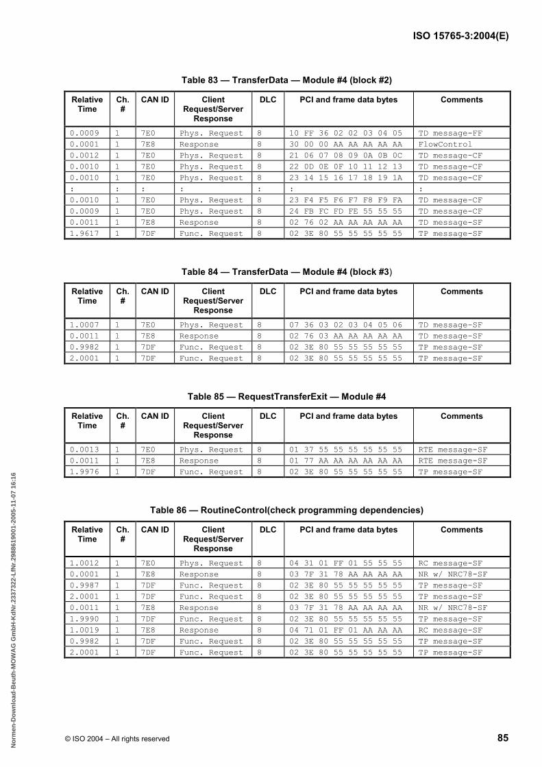
ISO 15765-3:2004(E)
© ISO 2004 – All rights reserved 85
Table 83 — TransferData — Module #4 (block #2)
Relative Time
Ch. #
CAN ID Client Request/Server
Response
DLC PCI and frame data bytes Comments
0.0009 1 7E0 Phys. Request 8 10 FF 36 02 02 03 04 05 TD message-FF 0.0001 1 7E8 Response 8 30 00 00 AA AA AA AA AA FlowControl 0.0012 1 7E0 Phys. Request 8 21 06 07 08 09 0A 0B 0C TD message-CF 0.0010 1 7E0 Phys. Request 8 22 0D 0E 0F 10 11 12 13 TD message-CF 0.0010 1 7E0 Phys. Request 8 23 14 15 16 17 18 19 1A TD message-CF : : : : : : : 0.0010 1 7E0 Phys. Request 8 23 F4 F5 F6 F7 F8 F9 FA TD message-CF 0.0009 1 7E0 Phys. Request 8 24 FB FC FD FE 55 55 55 TD message-CF 0.0011 1 7E8 Response 8 02 76 02 AA AA AA AA AA TD message-SF 1.9617 1 7DF Func. Request 8 02 3E 80 55 55 55 55 55 TP message-SF
Table 84 — TransferData — Module #4 (block #3)
Relative Time
Ch. #
CAN ID Client Request/Server
Response
DLC PCI and frame data bytes Comments
1.0007 1 7E0 Phys. Request 8 07 36 03 02 03 04 05 06 TD message-SF 0.0011 1 7E8 Response 8 02 76 03 AA AA AA AA AA TD message-SF 0.9982 1 7DF Func. Request 8 02 3E 80 55 55 55 55 55 TP message-SF 2.0001 1 7DF Func. Request 8 02 3E 80 55 55 55 55 55 TP message-SF
Table 85 — RequestTransferExit — Module #4
Relative Time
Ch. #
CAN ID Client Request/Server
Response
DLC PCI and frame data bytes Comments
0.0013 1 7E0 Phys. Request 8 01 37 55 55 55 55 55 55 RTE message-SF 0.0011 1 7E8 Response 8 01 77 AA AA AA AA AA AA RTE message-SF 1.9976 1 7DF Func. Request 8 02 3E 80 55 55 55 55 55 TP message-SF
Table 86 — RoutineControl(check programming dependencies)
Relative Time
Ch. #
CAN ID Client Request/Server
Response
DLC PCI and frame data bytes Comments
1.0012 1 7E0 Phys. Request 8 04 31 01 FF 01 55 55 55 RC message-SF 0.0001 1 7E8 Response 8 03 7F 31 78 AA AA AA AA NR w/ NRC78-SF 0.9987 1 7DF Func. Request 8 02 3E 80 55 55 55 55 55 TP message-SF 2.0001 1 7DF Func. Request 8 02 3E 80 55 55 55 55 55 TP message-SF 0.0011 1 7E8 Response 8 03 7F 31 78 AA AA AA AA NR w/ NRC78-SF 1.9990 1 7DF Func. Request 8 02 3E 80 55 55 55 55 55 TP message-SF 1.0019 1 7E8 Response 8 04 71 01 FF 01 AA AA AA RC message-SF 0.9982 1 7DF Func. Request 8 02 3E 80 55 55 55 55 55 TP message-SF 2.0001 1 7DF Func. Request 8 02 3E 80 55 55 55 55 55 TP message-SF
B55EB1B3C7662F79D1B59483A53B9F2F82C98BEEB7939EA95CF14FFEE5FB13B925D84A2690B319CCC3FB33EC1A0EE19ACE32C3AD48AA2003E27076E26B823E886461F4EB146348E75A2E06040CBB18
No
rmen
-Do
wn
load
-Beu
th-M
OW
AG
Gm
bH
-Kd
Nr.
2337
322-
LfN
r.29
8861
9001
-200
5-11
-07
16:1
6

ISO 15765-3:2004(E)
86 © ISO 2004 – All rights reserved
Table 87 — WriteDataByIdentifier — dataIdentifier = VIN
Relative Time
Ch. #
CAN ID Client Request/Server
Response
DLC PCI and frame data bytes Comments
0.0004 1 7E0 Phys. Request 8 10 14 2E F1 90 57 41 4C WDBI message-FF 0.0001 1 7E8 Response 8 30 00 00 AA AA AA AA AA FlowControl 0.0012 1 7E0 Phys. Request 8 21 54 4F 4E 53 2D 57 45 WDBI message-CF 0.0010 1 7E0 Phys. Request 8 22 42 2E 43 4F 4D 20 20 WDBI message-CF 0.0011 1 7E8 Response 8 03 6E F1 90 AA AA AA AA WDBI message-SF 1.9961 1 7DF Func. Request 8 02 3E 80 55 55 55 55 55 TP message-SF 2.0001 1 7DF Func. Request 8 02 3E 80 55 55 55 55 55 TP message-SF
10.4.4 Programming phase #1 — Post-Programming step
See Table 88.
Table 88 — ECUReset — hardReset
Relative Time
Ch. #
CAN ID Client Request/Server
Response
DLC PCI and frame data bytes Comments
0.3946 1 7DF Func. Request 8 02 11 01 55 55 55 55 55 ER message-SF 0.0011 1 7E8 Response 8 02 51 01 AA AA AA AA AA ER message-SF 0.0001 1 7E9 Response 8 02 51 01 AA AA AA AA AA ER message-SF
B55EB1B3C7662F79D1B59483A53B9F2F82C98BEEB7939EA95CF14FFEE5FB13B925D84A2690B319CCC3FB33EC1A0EE19ACE32C3AD48AA2003E27076E26B823E886461F4EB146348E75A2E06040CBB18
No
rmen
-Do
wn
load
-Beu
th-M
OW
AG
Gm
bH
-Kd
Nr.
2337
322-
LfN
r.29
8861
9001
-200
5-11
-07
16:1
6

ISO 15765-3:2004(E)
© ISO 2004 – All rights reserved 87
Annex A (normative)
Network configuration dataIdentifier definitions
A.1 Network configuration dataIdentifier definitions
The network configuration data related dataIdentifiers that can be read via the ReadDataByIdentifier (22 hex) service can be used by external test equipment or any other client to read out information about the communication protocol and CAN network configuration supported by the vehicle communication system. The client can request information about
the addressing scheme that shall be used,
the CAN identifiers that shall be used by the client and the server(s) for the subsequent communication, and
the servers that are connected to a remote network.
The network configuration data allows the client to dynamically set-up the communication configuration and adopt the addressing format and parameters provided by the vehicle system server(s).
The network configuration data will be requested via the ReadDataByIdentifier (22 hex) service using either physical or functional addressing.
Any server can support the dataIdentifiers defined below. In most cases, the server is the Diagnostic Configuration Master. A system may have a Diagnostic Configuration Master, but it is also possible to let individual servers directly report their own data.
Table A.1 defines the dataIdentifier values applicable for network configuration data (see ISO 14229-1 for the reserved range of dataIdentifiers for network configuration data).
B55EB1B3C7662F79D1B59483A53B9F2F82C98BEEB7939EA95CF14FFEE5FB13B925D84A2690B319CCC3FB33EC1A0EE19ACE32C3AD48AA2003E27076E26B823E886461F4EB146348E75A2E06040CBB18
No
rmen
-Do
wn
load
-Beu
th-M
OW
AG
Gm
bH
-Kd
Nr.
2337
322-
LfN
r.29
8861
9001
-200
5-11
-07
16:1
6

ISO 15765-3:2004(E)
88 © ISO 2004 – All rights reserved
Table A.1 — dataIdentifier definitions for network configuration data
Hex Description Cvt. Mnemonic
F010 addressFormat U AF This value shall cause the Diagnostic Configuration Master server to report which addressing
scheme shall be used for the subsequent communication.
F011 responseCANId U RSPCID This value shall cause the Diagnostic Configuration Master server, or any other server, to
report a list of CAN Ids that will be used by vehicle servers for responses during the subsequent communication. The list shall contain all response CAN Ids that are associated with the target address included in the request message to the Diagnostic Configuration Server (or any other server). This means that if a functional target address is used for the request, then the response shall contain a list of all CAN Ids that will be used by servers supporting that functional target address. If a physical target address is used for the request, then the response shall contain the CAN Id that will be used for responses from the server having that physical target address.
F012 physicalRequestCANId U PRQCID This value shall cause the Diagnostic Configuration Master server, or any other server/servers, to report a list of all CAN Ids that shall be used by the client to send physically addressed request messages during the subsequent communication. The response is depending on whether the request is sent with a functional or physical target address. If a functional target address is used for the request, the response shall either contain a list with all CAN Ids that shall be used by the client for physically addressed requests to any server in the vehicle system (in this case shall only one server respond), or each responding server shall send a list with one CAN Id that shall be used for physically addressed requests to that server.
NOTE For vehicle systems using extended addressing, there is always only one CAN Id in this list.
If a physical target address is used for the request, the response shall contain the CAN Id that shall be used for requests to the server having that physical target address.
F013 functionalRequestCANId U FRQCID This value shall cause the Diagnostic Configuration Master server, or any other server, to report the CAN Id that shall be used during the subsequent communication, by the client, for functionally addressed request messages, corresponding to the functional address included in the request message.
For vehicle systems using extended addressing, the same CAN Id is always used for all functionally addressed request messages.
F014 allFunctionalRequestCANIds U AFRQCID This value shall cause the Diagnostic Configuration Master server, or any other server, to report a list of all CAN Ids that shall be used by the client, to send functionally addressed request messages, during the subsequent communication.
NOTE For vehicle systems using extended addressing, there is always only one CAN Id in this list.
F015 remoteServerAddress U RSA This value shall cause the Remote Diagnostic Configuration Master server, or any other
server, to report a list of remote server identifiers (server target/source addresses) for servers connected to a remote network. The response is depending on whether the request is sent with a functional or physical remote target address. If a functional remote target address is used for the request, then each remote server shall send a response message with its own remote server identifier. If a physical remote target address is used for the request, then the Remote Diagnostic Configuration Master server, or any other server, shall sent a list including the remote server identifiers for all remote servers on the remote network.
F016 serverDiagnosticAddress U SDA This value shall cause the server(s) to report its (their) physical diagnostic address(es).
Independent of the addressing method used in the request message, the response always contains the single diagnostic address (target address) of the requested server(s).
B55EB1B3C7662F79D1B59483A53B9F2F82C98BEEB7939EA95CF14FFEE5FB13B925D84A2690B319CCC3FB33EC1A0EE19ACE32C3AD48AA2003E27076E26B823E886461F4EB146348E75A2E06040CBB18
No
rmen
-Do
wn
load
-Beu
th-M
OW
AG
Gm
bH
-Kd
Nr.
2337
322-
LfN
r.29
8861
9001
-200
5-11
-07
16:1
6

ISO 15765-3:2004(E)
© ISO 2004 – All rights reserved 89
A.2 Network configuration dataIdentifier data format definitions
Tables A.2 to A.5 define the data parameter format and the content of the network configuration dataIdentifiers as given in Table A.1.
Tables A.6 to A.11 define the data parameter values of the dataIdentifier defined in Tables A.2 to A.5.
Table A.2 — addressFormat dataIdentifier data format recordDataIdentifier = addressFormat
Byte pos. Parameter Name Cvt. Hex Value Mnemonic
#1
dataRecord[] = [ serverAddressFormat ]
M
00-FF
DREC_ DATA_1
Table A.3 — CAN Id related dataIdentifier's data format recordDataIdentifier = physicalRequestCANId, functionalRequestCANId, allFunctionalRequestCANIds
Byte pos. Parameter Name Cvt. Hex Value Mnemonic
#1 #2 #3 #4 #5 :
#n-4 #n-3 #n-2 #n-1 #n
dataRecord[] = [ diagnosticAddress #1 CANIdBits24to28 #1 CANIdBits16to23 #1 CANIdBits8to15 #1 CANIdBits0to7 #1 : diagnosticAddress #m CANIdBits24to28 #m CANIdBits16to23 #m CANIdBits8to15 #m CANIdBits0to7 #m ]
M M M M M : C C C C C
00-FF 00-FF 00-FF 00-FF 00-FF
: 00-FF 00-FF 00-FF 00-FF 00-FF
DREC_ DATA_1 DATA_2 DATA_3 DATA_4 DATA_5
: DATA_(n-4) DATA_(n-3) DATA_(n-2) DATA_(n-1)
DATA_n
C The Diagnostic Configuration Master might report multiple diagnosticAddress and CAN Ids sets, depending on the target address used in the request message that causes the diagnostic configuration master to respond (see network configuration data dataIdentifier definitions for more details).
Table A.4 — Diagnostic address-related dataIdentifier's data format recordDataIdentifier = diagnosticAddress
Byte pos. Parameter Name Cvt. Hex Value Mnemonic
#1
dataRecord[] = [ diagnosticAddress ]
M
00-FF
DREC_ DATA_1
Table A.5 — addressFormat dataIdentifier data format recordDataIdentifier = remoteServerAddress
Byte pos. Parameter Name Cvt. Hex Value Mnemonic
#1 :
#n
dataRecord[] = [ remoteServerAddress #1 : remoteServerAddress #m ]
M : C
00-FF
: 00-FF
DREC_ DATA_1
: DATA_n
C In case there are multiple remote servers, then this parameter is present. The format of the remoteServerAddress is identical to the format of the diagnosticAddress parameter.
B55EB1B3C7662F79D1B59483A53B9F2F82C98BEEB7939EA95CF14FFEE5FB13B925D84A2690B319CCC3FB33EC1A0EE19ACE32C3AD48AA2003E27076E26B823E886461F4EB146348E75A2E06040CBB18
No
rmen
-Do
wn
load
-Beu
th-M
OW
AG
Gm
bH
-Kd
Nr.
2337
322-
LfN
r.29
8861
9001
-200
5-11
-07
16:1
6
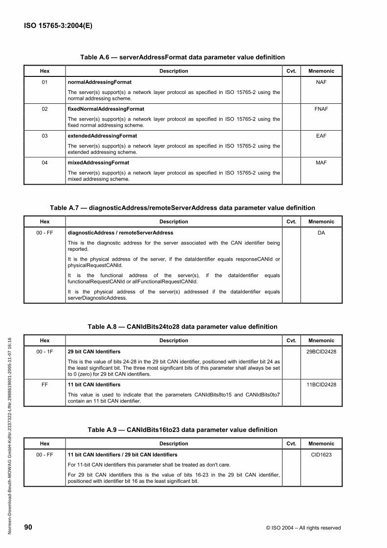
ISO 15765-3:2004(E)
90 © ISO 2004 – All rights reserved
Table A.6 — serverAddressFormat data parameter value definition
Hex Description Cvt. Mnemonic
01 normalAddressingFormat NAF
The server(s) support(s) a network layer protocol as specified in ISO 15765-2 using the normal addressing scheme.
02 fixedNormalAddressingFormat FNAF
The server(s) support(s) a network layer protocol as specified in ISO 15765-2 using the fixed normal addressing scheme.
03 extendedAddressingFormat EAF
The server(s) support(s) a network layer protocol as specified in ISO 15765-2 using the extended addressing scheme.
04 mixedAddressingFormat MAF
The server(s) support(s) a network layer protocol as specified in ISO 15765-2 using the mixed addressing scheme.
Table A.7 — diagnosticAddress/remoteServerAddress data parameter value definition
Hex Description Cvt. Mnemonic
00 - FF diagnosticAddress / remoteServerAddress DA
This is the diagnostic address for the server associated with the CAN identifier being reported.
It is the physical address of the server, if the dataIdentifier equals responseCANId or physicalRequestCANId.
It is the functional address of the server(s), if the dataIdentifier equals functionalRequestCANId or allFunctionalRequestCANId.
It is the physical address of the server(s) addressed if the dataIdentifier equals serverDiagnosticAddress.
Table A.8 — CANIdBits24to28 data parameter value definition
Hex Description Cvt. Mnemonic
00 - 1F 29 bit CAN Identifiers 29BCID2428
This is the value of bits 24-28 in the 29 bit CAN identifier, positioned with identifier bit 24 as the least significant bit. The three most significant bits of this parameter shall always be set to 0 (zero) for 29 bit CAN identifiers.
FF 11 bit CAN Identifiers 11BCID2428
This value is used to indicate that the parameters CANIdBits8to15 and CANIdBits0to7 contain an 11 bit CAN identifier.
Table A.9 — CANIdBits16to23 data parameter value definition
Hex Description Cvt. Mnemonic
00 - FF 11 bit CAN Identifiers / 29 bit CAN Identifiers CID1623
For 11-bit CAN identifiers this parameter shall be treated as don't care.
For 29 bit CAN identifiers this is the value of bits 16-23 in the 29 bit CAN identifier, positioned with identifier bit 16 as the least significant bit.
B55EB1B3C7662F79D1B59483A53B9F2F82C98BEEB7939EA95CF14FFEE5FB13B925D84A2690B319CCC3FB33EC1A0EE19ACE32C3AD48AA2003E27076E26B823E886461F4EB146348E75A2E06040CBB18
No
rmen
-Do
wn
load
-Beu
th-M
OW
AG
Gm
bH
-Kd
Nr.
2337
322-
LfN
r.29
8861
9001
-200
5-11
-07
16:1
6

ISO 15765-3:2004(E)
© ISO 2004 – All rights reserved 91
Table A.10 — CANIdBits8to15 data parameter value definition
Hex Description Cvt. Mnemonic
00 - FF 11 bit CAN Identifiers / 29 bit CAN Identifiers CID0815
For 11 bit CAN identifiers this is the value of bits 8-10 in the 11 bit CAN identifier, positioned with identifier bit 8 as the least significant bit. The five most significant bits of this parameter shall be treated as don't care.
For 29 bit CAN identifiers this is the value of bits 8-15 in the 29 bit CAN identifier, positioned with identifier bit 8 as the least significant bit.
Table A.11 — CANIdBits0to7 data parameter value definition
Hex Description Cvt. Mnemonic
00 - FF 11 bit CAN Identifiers / 29 bit CAN Identifiers CID0007
For 11 bit and 29 bit CAN identifiers this is the value of bits 0-7 in the CAN identifier, positioned with identifier bit 0 as the least significant bit.
B55EB1B3C7662F79D1B59483A53B9F2F82C98BEEB7939EA95CF14FFEE5FB13B925D84A2690B319CCC3FB33EC1A0EE19ACE32C3AD48AA2003E27076E26B823E886461F4EB146348E75A2E06040CBB18
No
rmen
-Do
wn
load
-Beu
th-M
OW
AG
Gm
bH
-Kd
Nr.
2337
322-
LfN
r.29
8861
9001
-200
5-11
-07
16:1
6

ISO 15765-3:2004(E)
92 © ISO 2004 – All rights reserved
Bibliography
[1] ISO/TR 8509, Information processing systems — Open Systems Interconnection — Service conventions
[2] ISO/IEC 7498 (all parts), Information technology — Open Systems Interconnection — Basic Reference Model
[3] ISO/IEC 10731, Information technology — Open Systems Interconnection — Basic Reference Model — Conventions for the definition of OSI services
[4] SAE J1850, Class B Data Communications Network Interface
B55EB1B3C7662F79D1B59483A53B9F2F82C98BEEB7939EA95CF14FFEE5FB13B925D84A2690B319CCC3FB33EC1A0EE19ACE32C3AD48AA2003E27076E26B823E886461F4EB146348E75A2E06040CBB18
No
rmen
-Do
wn
load
-Beu
th-M
OW
AG
Gm
bH
-Kd
Nr.
2337
322-
LfN
r.29
8861
9001
-200
5-11
-07
16:1
6

This page is intentionally blank.
B55EB1B3C7662F79D1B59483A53B9F2F82C98BEEB7939EA95CF14FFEE5FB13B925D84A2690B319CCC3FB33EC1A0EE19ACE32C3AD48AA2003E27076E26B823E886461F4EB146348E75A2E06040CBB18
No
rmen
-Do
wn
load
-Beu
th-M
OW
AG
Gm
bH
-Kd
Nr.
2337
322-
LfN
r.29
8861
9001
-200
5-11
-07
16:1
6

ISO 15765-3:2004(E)
ICS 43.040.15 Price based on 92 pages
© ISO 2004 – All rights reserved
B55EB1B3C7662F79D1B59483A53B9F2F82C98BEEB7939EA95CF14FFEE5FB13B925D84A2690B319CCC3FB33EC1A0EE19ACE32C3AD48AA2003E27076E26B823E886461F4EB146348E75A2E06040CBB18
No
rmen
-Do
wn
load
-Beu
th-M
OW
AG
Gm
bH
-Kd
Nr.
2337
322-
LfN
r.29
8861
9001
-200
5-11
-07
16:1
6