international stunt winner building notes the ribs and spar over the plan. before gluing anything...
TRANSCRIPT
INTERNATIONAL STUNT WINNER BUILDING NOTES *Some details may have been changed or added to the kit after the prototype was assembled and may or may not show in
some photos. Construction of the wing is basically put together unglued up to the installation of the Leading edge stick.
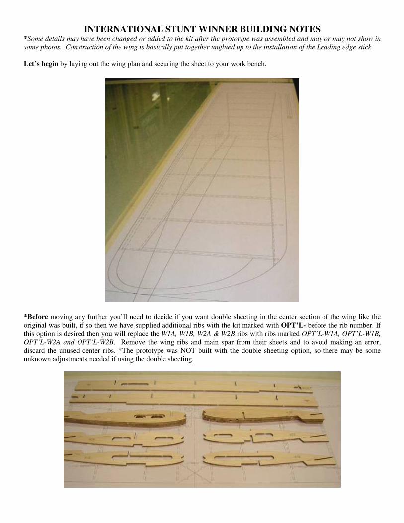
Let’s begin by laying out the wing plan and securing the sheet to your work bench.
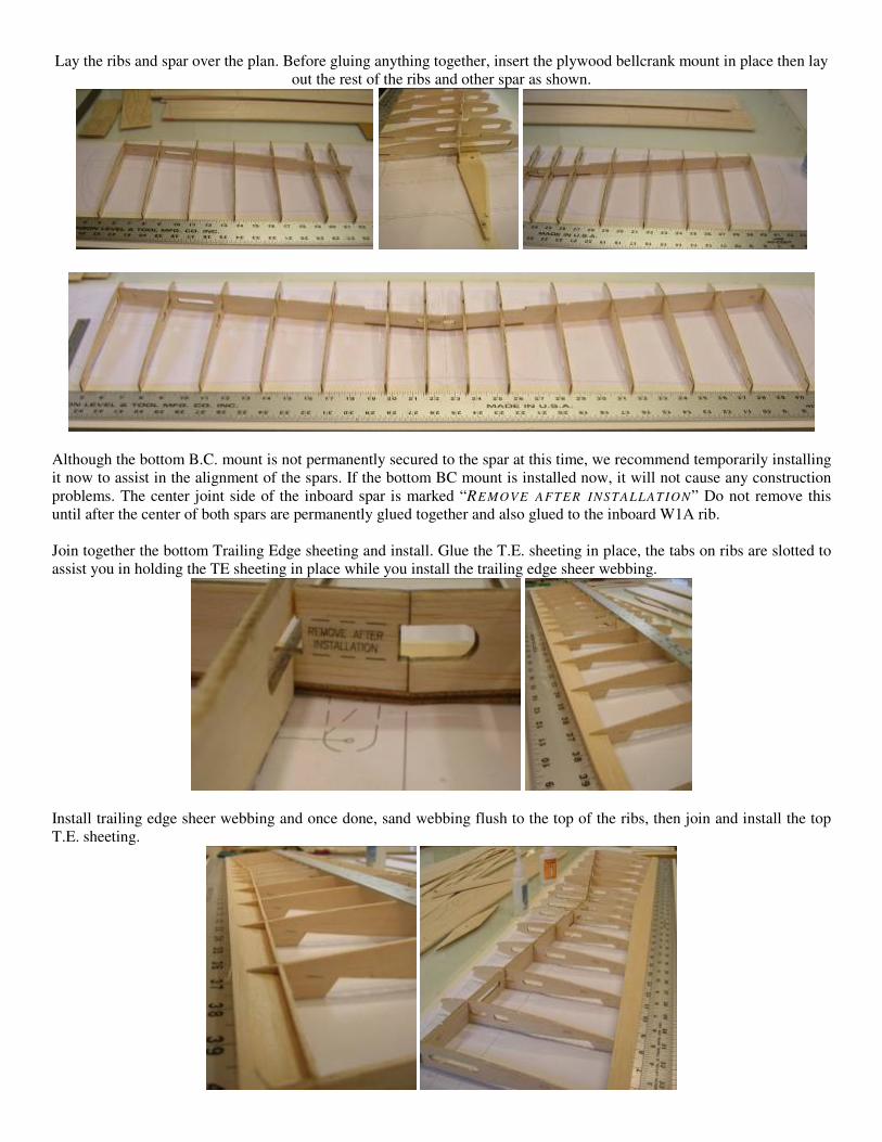
*Before moving any further you’ll need to decide if you want double sheeting in the center section of the wing like the
original was built, if so then we have supplied additional ribs with the kit marked with OPT’L- before the rib number. If
this option is desired then you will replace the W1A, W1B, W2A & W2B ribs with ribs marked OPT’L-W1A, OPT’L-W1B,
OPT’L-W2A and OPT’L-W2B. Remove the wing ribs and main spar from their sheets and to avoid making an error,
discard the unused center ribs. *The prototype was NOT built with the double sheeting option, so there may be some
unknown adjustments needed if using the double sheeting.
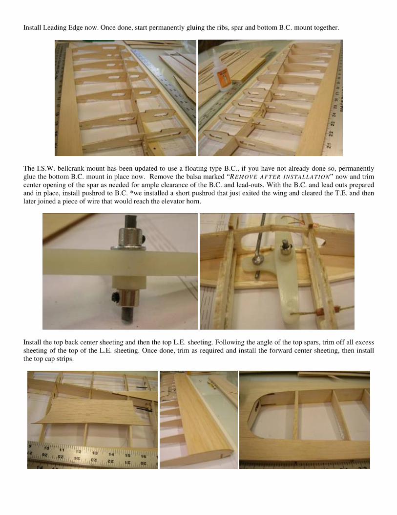
Lay the ribs and spar over the plan. Before gluing anything together, insert the plywood bellcrank mount in place then lay
out the rest of the ribs and other spar as shown.
Although the bottom B.C. mount is not permanently secured to the spar at this time, we recommend temporarily installing
it now to assist in the alignment of the spars. If the bottom BC mount is installed now, it will not cause any construction
problems. The center joint side of the inboard spar is marked “REMOVE AFTER INSTALLAT ION” Do not remove this
until after the center of both spars are permanently glued together and also glued to the inboard W1A rib.
Join together the bottom Trailing Edge sheeting and install. Glue the T.E. sheeting in place, the tabs on ribs are slotted to
assist you in holding the TE sheeting in place while you install the trailing edge sheer webbing.
Install trailing edge sheer webbing and once done, sand webbing flush to the top of the ribs, then join and install the top
T.E. sheeting.
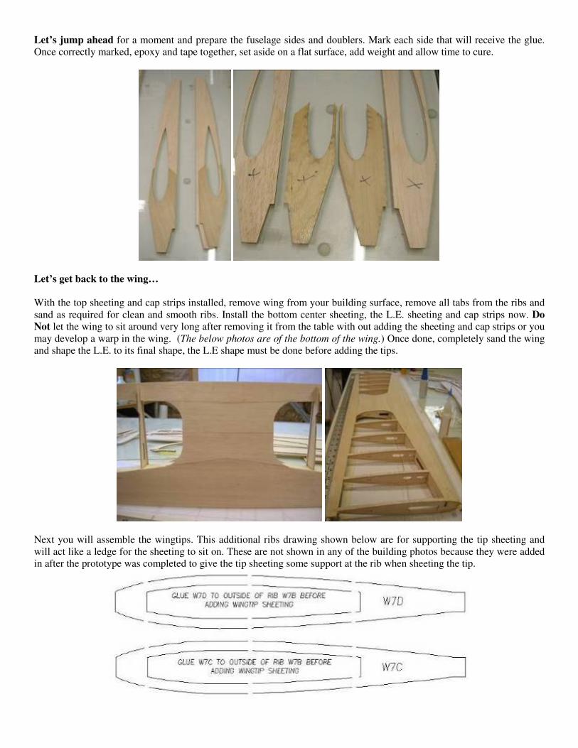
Install Leading Edge now. Once done, start permanently gluing the ribs, spar and bottom B.C. mount together.
The I.S.W. bellcrank mount has been updated to use a floating type B.C., if you have not already done so, permanently
glue the bottom B.C. mount in place now. Remove the balsa marked “REMOVE AFTER INSTALL ATION” now and trim
center opening of the spar as needed for ample clearance of the B.C. and lead-outs. With the B.C. and lead outs prepared
and in place, install pushrod to B.C. *we installed a short pushrod that just exited the wing and cleared the T.E. and then
later joined a piece of wire that would reach the elevator horn.
Install the top back center sheeting and then the top L.E. sheeting. Following the angle of the top spars, trim off all excess
sheeting of the top of the L.E. sheeting. Once done, trim as required and install the forward center sheeting, then install
the top cap strips.
Let’s jump ahead for a moment and prepare the fuselage sides and doublers. Mark each side that will receive the glue.
Once correctly marked, epoxy and tape together, set aside on a flat surface, add weight and allow time to cure.
Let’s get back to the wing…
With the top sheeting and cap strips installed, remove wing from your building surface, remove all tabs from the ribs and
sand as required for clean and smooth ribs. Install the bottom center sheeting, the L.E. sheeting and cap strips now. Do
Not let the wing to sit around very long after removing it from the table with out adding the sheeting and cap strips or you
may develop a warp in the wing. (The below photos are of the bottom of the wing.) Once done, completely sand the wing
and shape the L.E. to its final shape, the L.E shape must be done before adding the tips.
Next you will assemble the wingtips. This additional ribs drawing shown below are for supporting the tip sheeting and
will act like a ledge for the sheeting to sit on. These are not shown in any of the building photos because they were added
in after the prototype was completed to give the tip sheeting some support at the rib when sheeting the tip.

*The Inboard side is just a little different from the outboard side, so separate the parts before hand.
Inboard tip: Glue the front and rear balsa spacers and one of the plywood tip exit doublers to the bottom main tip frame.
Once done, add the top main tip frame and your inboard tip is assembled, do not sand at this time. See photos below.
With the tip mounted to the wing, bevel the front and rear edges of your adjustable lead-out guide and install now,
reinforce as desired. Once done, use a sanding block to sand only a slight angle to the edges of the wingtip frame at this
time. Add the additional support rib (7C) now and then sheet both sides of the wingtip. Sand edges to desired roundness
and your inboard wingtip is done…

Outboard tip: Laminate the three main tip frames together, install tip onto the wing.
*The wingtip sheeting has been cut oversize, so test fitting the sheeting first will allow you to see what is needed and what
we want you to do here.
With the O.B. wingtip mounted to the wing, sand the L.E. of the wingtip flush with the L.E. of the wing but do not round
off the wingtip just yet. Add the additional support rib (7D) now and then, using a sanding block, sand only a slight angle
to edges of the wingtip frame at this time. Once done, install the bottom wingtip sheeting and install your wingtip weight
or… *If you’re using an adjustable tip weight box; carefully cut out an opening for the adjustable tip weight box. Make
sure the entire plywood box is in the tip deep enough so the balsa cover just slightly exits the sheeting. Using some scrap
balsa, sand/shape three small pieces of balsa and add around the tip weight box to support the sheeting from collapsing.
Once done, sand the wingtip to match the roundness of the I.B. wingtip and your outboard wingtip is also done…
Sand entire wing, cap strips and tip sheeting to match and your wing is done.

Fuselage Construction: We have modernized the nose by adding a balsa crutch to it, start the fuselage construction by marking the maple mounts
for the plywood bulkheads, and then cut the 1/2” balsa to fit between bulkheads F1A-B, F1B, F2 and F3M. Once done,
use a slow curing epoxy to assemble the crutch, this will allow you time to make adjustments and square things up. Insert
the cross grain 1/2" balsa and bulkheads F1B and F2 between the maple mounts now. Tape or clamp together and set
aside to cure.
While the crutch assembly is curing, mark the insides of the fuselage to receive the crutch and bulkhead assembly and all
other balsa formers, then line up the mounts to the front of the fuselage and mark the back end of the mounts to follow the
shape of wing opening and cut off the excess mounts and crutch as shown below. Once done, use a slow curing epoxy;
permanently install the crutch assembly.
With the nose assembly completed, start inserting all the other formers leaving unglued for the time being, this will allow
you to check the straightness of the fuselage, this can be achieved by temporarily inserting the bottom laser cut fuselage
sheeting. If satisfied, remove the fuselage sheeting and permanently glue the formers in place.
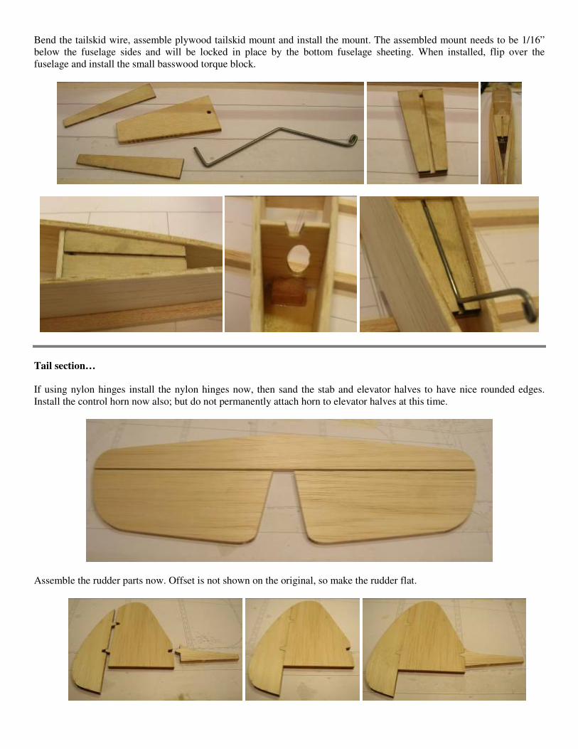
Bend the tailskid wire, assemble plywood tailskid mount and install the mount. The assembled mount needs to be 1/16”
below the fuselage sides and will be locked in place by the bottom fuselage sheeting. When installed, flip over the
fuselage and install the small basswood torque block.
Tail section…
If using nylon hinges install the nylon hinges now, then sand the stab and elevator halves to have nice rounded edges.
Install the control horn now also; but do not permanently attach horn to elevator halves at this time.
Assemble the rudder parts now. Offset is not shown on the original, so make the rudder flat.
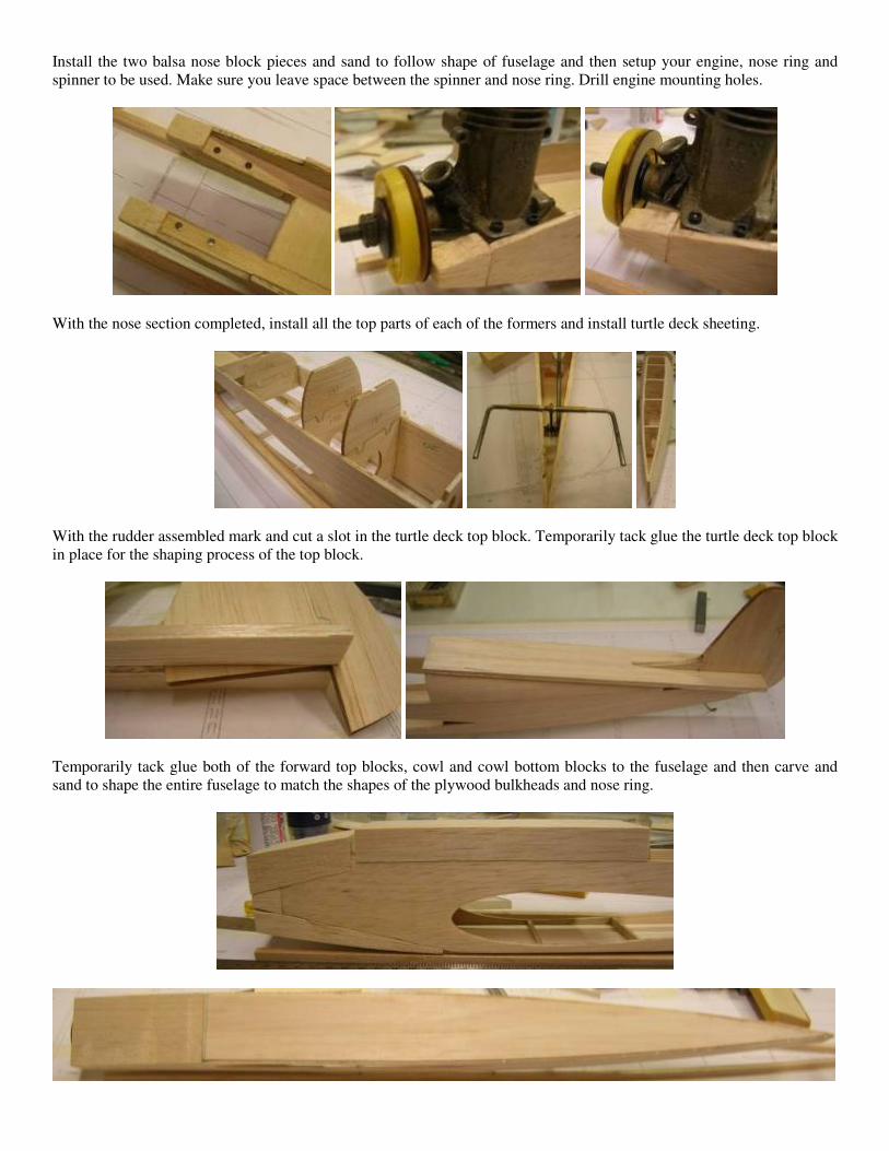
Install the two balsa nose block pieces and sand to follow shape of fuselage and then setup your engine, nose ring and
spinner to be used. Make sure you leave space between the spinner and nose ring. Drill engine mounting holes.
With the nose section completed, install all the top parts of each of the formers and install turtle deck sheeting.
With the rudder assembled mark and cut a slot in the turtle deck top block. Temporarily tack glue the turtle deck top block
in place for the shaping process of the top block.
Temporarily tack glue both of the forward top blocks, cowl and cowl bottom blocks to the fuselage and then carve and
sand to shape the entire fuselage to match the shapes of the plywood bulkheads and nose ring.

Once satisfied with the shape of your fuselage; trim and fit canopy during this phase of the fuselage construction. Fit all
the components together, make adjustments if needed. Install the gear and gear blocks, make your cowl hold downs, and
then start to permanently assemble the model making sure you have permanently installed and secured the controls,
pushrod, wing and tail. Once done, sand entire model as needed for nice clean fits with the canopy, cowl / engine opening
and wing and tail fillets. We recommend the using leather fillets for the wing and stab areas. Prep model, cover and dope
as desired before installing any fillets.
We do carry leather fillets for those that use them; leather fillets can be purchased from us if desired. Our direct web page
link for the fillets can be found on our website at: http://www.builtrightflyright.com/MiscPgs/leather/leatherfillets.htm
Okay you’re pretty much done and we’re sure you can take it from here. Should you need any assistance with your
INTERNATIONAL STUNT WINNER kit, please do not hesitate to contact us at:
A downloadable copy of these building notes with photos can be printed from our website at:
http://www.builtrightflyright.com/New_Web_Pgs/kits/IntStntWinnr/isw.htm
Thank you and good luck…
Below is the framed up INTERNATIONAL STUNT WINNER kit prototype.
Red’s Original INTERNATIONAL STUNT WINNER