internet-based simulation and virtual world for engineering
TRANSCRIPT

Sun, Gramoll 13
w i n t e r 2 0 0 4
Internet-based Simulation and Virtual World for Engineering Education
Qiuli Sun, Kurt GramollThe University of Oklahoma
Abstract
In this paper the use of an Internet-based structural simulation and a 3D virtual world to view structures
for engineering education was investigated. The generic truss and frame structural simulation allows the
user to construct a truss or frame structure, apply boundary conditions, and place forces to any joint over
the Internet. The computational results are also visually presented. For trusses, both the displacement
and member loads are displayed. Different colors are used to demonstrate the load level in each member.
For frame structures, moment, shear and axial diagrams are constructed in addition to deflection curves.
Finite element method is used to compute all results. Vector-based graphics are used for structure devel-
opment and results presentation to reduce file size and downloading times. In addition to any general
trusses or frames, a special case study of bridge construction was included in the simulation. The user
can draw the bridge, analyze it, and animate a typical moving vehicle over the bridge. The user can also
deposit the bridge into an Internet-based 3D virtual world, which provides a 'big picture' of the bridge.
Assessment was conducted to determine the effectiveness of the simulation. The results showed that the
simulation was helpful in visualizing the computational results and reinforcing the understanding of the
concepts of the truss and frame structures. To develop the simulation and the virtual world, Shockwave,
VRML, ASP, SQL, and Perl were utilized together and programmed so that they communicate smoothly
with each other. The simulation and 3D virtual world is open to the public at www.vcity.ou.edu. The
structural analysis simulation is just one component at this virtual world design web-portal.
IntroductionAs student populations increase, uni-
versities face the challenge of maintain-ing high standards and effective education (Lacy, 2000). This is particularly true in the resource-intensive engineering field. Also, in industry, as technological innovations are rapidly taking place, engineers and techni-cians must always continue to learn and mas-ter new technologies. Hence, efficient and inexpensive methods must be found to com-plement traditional education and training. One solution is to employ the Internet with its advantages of low cost, convenience and collaboration. With the help of the Internet, new approaches, such as Internet-based sim-ulations and virtual worlds, can be adopted to help teach engineering concepts.
In order to make use of the Internet's unique features for education, a project called
Sooner City was initiated at the University of Oklahoma in 1998 (Sun & Gramoll, 1999). A Virtual City framework was proposed to investigate the Internet-based environment for engineering education, design, and analy-sis (Sun & Gramoll, 2001). The framework adopts a three-tier architecture: an online database, a Web sever, and client browsers. The Virtual City is composed of five com-ponents: a 3D virtual world, multiple mul-timedia modules, an online database, a col-laborative geometric modeling module, and a collaborative engineering analysis module. To illustrate the use of the Internet for educa-tion, this paper presents the structural analy-sis module and the 3D virtual world in detail. The structural analysis module and virtual world are examples that can serve as proto-types for Internet-based engineering educa-tion. There are also other modules at the web site, in addition to the structural analysis

14 Engineering Design Graphics Journal
v o l u m e 6 8 n u m b e r 1
module, that tie other aspects of undergradu-ate civil engineering courses together into the virtual world.
There are other examples of Internet-based simulations to assist engineering stu-dents in learning basic principals. Included is "Mallard" which was developed by Mike Swafford and Donna Brown at the University of Illinois at Urbana-Champaign (Graham & Trick, 1998). Two interactive Web-based applications called Virtual FlyLab and Virtual Earthquake were developed for learning science (Desharnais & Novak, 1998). An innovative use of Internet tech-nologies for education is to employ Virtual Reality Modeling Language (VRML) to teach design over the Internet. Ranga and Gramoll successfully implemented two Internet-based design examples with the help of Practical Extraction and Reporting Language (Perl) (Ranga& Gramoll, 1999). Peterson utilized VRML and Java in teach-ing machine kinematics (Peterson, 1997). Shockwave is also a widely used Internet technology to design simulations. A num-ber of Shockwave simulations have been
developed to teach specific engineering topics (Sun & Grammol, 1999 & 2000). Multiverse is another example providing a standard interface for various Internet-based simulations (Austin & Liddle, 1998; Thomas& Liddle, 1998) that facilitate the use of Internet-based simulation in educa-tion and training by employing Java and Web technologies.
Although educational activities over the Internet are diverse and Internet-based edu-cation is maturing, it is interesting to note that in the course of this project, no exist-ing educational program was found to have implemented 3D visualization and generic simulations with flexible graphic input. Therefore, one of the goals of this project is to present an Internet-based prototype virtual world for 3D visualization. Because it is always difficult to provide the user with intuitive graphic input to simulations, the possibility of developing such a simula-tion was investigated in this project. Also, the concept of displaying 3D objects on the Internet and dynamically changing them for engineering education was demonstrated in
Figure 1

Sun, Gramoll 15
w i n t e r 2 0 0 4
this project.
Structural Analysis Module
In the Virtual City framework, there are nine multimedia modules developed for engi-neering education. In this paper, only the structural analysis module, designed for the Structural Analysis course at the University of Oklahoma, is presented. Its main purpose was to provide a generic solver for plane truss and frame problems. It is important for a structur-al designer to learn how to compute the forces and displacements of truss structures and how to compute the deflections, moments, shears and axial forces of frame structures. Although complex commercial finite element codes can be used, they are usually not readily available to students and have a steep learning curve. Thus it is particularly useful to provide a con-venient solver that can be used to check the computational results of trusses and frames.
The online structural analysis module con-tains two sections: an information section (Fig. 1), and a simulation section (Fig. 2). The information section covers basic concepts for four topic areas that include trusses, frames, stability, and the stiffness method. This sec-tion is to give the student background infor-mation about trusses and frames.
The second section is the actual simula-
tion that includes a help page. The simula-tion was programmed using Macromedia's Director that can be saved as an Internet-
based Shockwave file. The actual scripting or programming language in Director that was used is called Lingo. The simulation is basically a finite element method (FEM) solver for trusses and frames. Although it is easy to obtain the code of the computational procedures of FEM, programming FEM in Lingo was challenging since it is actually a scripting language that is not suited for matrix operations.
In addition to the actual FEM solver, the other main challenge to programming the simulation was the graphical input and out-put. It was important to design the interface so that any engineering student could eas-ily understand how to operate the program without the need of a reference manual or keeping track of node and element numbers. The purpose of the simulation was to help the student understand trusses and frames, and not FEM. Also, to minimize file size, all input and resulting graphics were based on vectors and not pixel-based graphics. Vector-based
Figure 3a
Figure 3b
Figure 2

16 Engineering Design Graphics Journal
v o l u m e 6 8 n u m b e r 1
graphics can be completely controlled by Lingo, therefore it is particularly efficient to create, move, and delete the graphics dynami-cally. Using vector-based graphics minimizes the simulation's file size to about the size of a large graphic file.
Basically, two types of structures can be solved using the simulation of this mod-ule — truss structures and frame structures. For truss structures, the user can draw any kind of valid truss structure, apply boundary conditions such as pinned joints and roller joints, and specify the forces to any node of the truss. Because each truss member is considered internally as an element, the user can draw only one member at a time. Only point forces can be applied to the node. The maximum number of total members is 85. The maximum number of joints is 13 for each type of joint. The maximum number of forces is 20 for each type of force. The simulation therefore cannot be used to solve large truss problems.
There are two ways to specify detail input information: the preference window and the member property window. Figure 3a illus-
trates the preference window of the simula-tion. In the preference window, the user can specify appropriate grid step ratio of the grid system to map real-world dimensions. The lengths of the members are determined implicitly based on the grid system. Default values for material and member geometric properties are also set in the preference win-dow. The user can also give material and geo-metric properties to individual members (Fig. 3b) by double clicking individual members.
The results for truss structures are presented in four ways: summary of results, report of individual members, displacement visualiza-
Figure 4
Figure 5

Sun, Gramoll 17
w i n t e r 2 0 0 4
tion (Fig. 4), and load visualization (Fig. 5). In the summary of results, the values of the maximum displacement and maximum stress are reported. If an individual member is double-clicked, its displacements and stress can be accessed. Also, the stability of each member is checked and reported based on the basic Euler equation. To demonstrate the relative difference of the displacement, a new truss structure with node movement based on the displacements is drawn. The color is uti-lized to show the loads in each member.
In addition to truss structures, the user can draw any type of frame structure. The number of members, joints, and forces are limited, similar to the truss structures. Point forces, moment, and distributed loads in x direction and y direction can be applied to the frame. By double-clicking the forces, the user can change their magnitudes. Similarly, the simulation reports a summary of the computational results, such as maximum dis-placement of nodes, maximum moment of nodes, and maximum axial force of members. Each member's deflection (Fig. 6), moment diagram (Fig. 7), shear diagram, axial force diagram can be visually presented.
The structural simulation is a generic appli-cation, and can be used to help develop various specific applications. One particular application, a bridge with a moving load, was a specific case that was programmed into the simulation due to its unique output needs. After the user chooses the bridge option, the number of the sections in the preference win-dow can be specified. Then the user needs to add the actual truss members between the
Figure 6
Figure 7
18 Engineering Design Graphics Journal
v o l u m e 6 8 n u m b e r 1
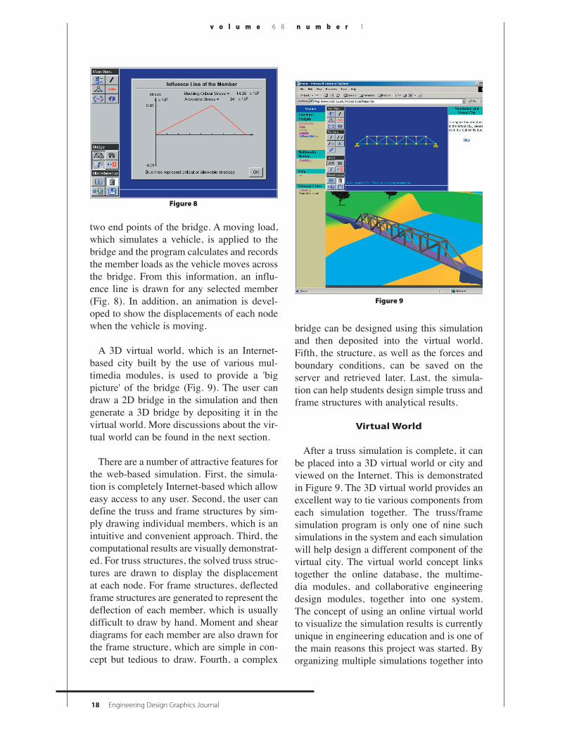
two end points of the bridge. A moving load, which simulates a vehicle, is applied to the bridge and the program calculates and records the member loads as the vehicle moves across the bridge. From this information, an influ-ence line is drawn for any selected member (Fig. 8). In addition, an animation is devel-oped to show the displacements of each node when the vehicle is moving.
A 3D virtual world, which is an Internet-based city built by the use of various mul-timedia modules, is used to provide a 'big picture' of the bridge (Fig. 9). The user can draw a 2D bridge in the simulation and then generate a 3D bridge by depositing it in the virtual world. More discussions about the vir-tual world can be found in the next section.
There are a number of attractive features for the web-based simulation. First, the simula-tion is completely Internet-based which allow easy access to any user. Second, the user can define the truss and frame structures by sim-ply drawing individual members, which is an intuitive and convenient approach. Third, the computational results are visually demonstrat-ed. For truss structures, the solved truss struc-tures are drawn to display the displacement at each node. For frame structures, deflected frame structures are generated to represent the deflection of each member, which is usually difficult to draw by hand. Moment and shear diagrams for each member are also drawn for the frame structure, which are simple in con-cept but tedious to draw. Fourth, a complex
bridge can be designed using this simulation and then deposited into the virtual world. Fifth, the structure, as well as the forces and boundary conditions, can be saved on the server and retrieved later. Last, the simula-tion can help students design simple truss and frame structures with analytical results.
Virtual World
After a truss simulation is complete, it can be placed into a 3D virtual world or city and viewed on the Internet. This is demonstrated in Figure 9. The 3D virtual world provides an excellent way to tie various components from each simulation together. The truss/frame simulation program is only one of nine such simulations in the system and each simulation will help design a different component of the virtual city. The virtual world concept links together the online database, the multime-dia modules, and collaborative engineering design modules, together into one system. The concept of using an online virtual world to visualize the simulation results is currently unique in engineering education and is one of the main reasons this project was started. By organizing multiple simulations together into
Figure 8
Figure 9

Sun, Gramoll 19
w i n t e r 2 0 0 4
a single world allows the user to better under-stand the overall design concepts of each component as it fits into the "big picture" (Fig. 10). Also, since it is Internet-based, it can be accessed by any student from any loca-tion with real-time collaboration.
The 3D virtual world was designed using VRML with the help of Perl, Active Service Page (ASP), Structured Query Language (SQL), and an online database (Fig. 11). These Internet technologies work together to generate 3D visual structures on the web page in real time. The steps to generate 3D structures are as follows. First, a Shockwave simulation is used to help design and prepare
the data for a particular design. For example, designing a bridge requires data that includes section numbers, node positions, and the layout of the bridge. Second, the data is trans-mitted from the simulation to the server. The server then starts a Perl program to take the data and generates a VRML format file of the structure. Since the simulation forces the vir-tual world to be updated simultaneously, the structure can be seen immediately. Third, the user can modify the structure by re-submit-ting new data. For instance, if the user dis-likes the layout of the generated bridge they can modify the previous bridge by adding, deleting, or moving trusses and resubmitting it to the server.
In addition to using Perl to create individual structures, the entire virtual world is dynami-cally generated and managed by an ASP script with the help of SQL statements that access the online database. The virtual world is a customized world belonging to individual users. It is inefficient and inconvenient to save multiple copies of the virtual worlds. One solution is to save only the customized parts of the virtual worlds and utilize a cre-
Figure 10
Figure 11

20 Engineering Design Graphics Journal
v o l u m e 6 8 n u m b e r 1
ative strategy to manage them. This strategy employs an ASP script to accept the user's account data as input. Based on the input data, the ASP script then searches the database to retrieve virtual structures associated with that particular user and dynamically generates the virtual world. Also, it is easy to set different default viewpoints for different simulations. The strategy is efficient because it does not save redundant data and can be used to man-age a large number of users.
AssessmentSince the structural analysis module was
developed for engineering education, it is important to evaluate its effectiveness. An assessment was therefore conducted at the University of Oklahoma in the fall of 2000. The professor first demonstrated in class how the module could be used to solve frame problems, and two homework problems were then assigned. The students were offered five bonus points for using the structural analysis module to check their homework solutions.
The survey questions and their correspond-ing results are shown in the Table 1. Twelve students in all responded to the survey. Table 2 summarizes the means and standard devia-tion performed on the student responses to the questions about the module.
From the responses to questions one and two, it was concluded that the module was successful in helping students better visual-
ize the computational results and understand the concepts of truss and frame structures. Based on the responses to question three, it was concluded that the students believed that the module was useful in checking homework solutions. The responses to questions four and five indicated that the module encouraged students to design new structures outside of the assigned homework and helped visualize 3D models. However, it is interesting to note that half of the respondents had no opinion in response to question five. This probably means that they did not try to design a bridge and deposit it into the 3D virtual world.
In addition to answering survey questions, these twelve students also provided useful comments about the structural analysis mod-ule. Examples of positive comments are, "If I would have learned to use this (module) earlier in this semester I think it would have
Questions1. How good is this module at helping you understand
the concepts of frame or truss structures?2. How good is this module at helping you better visual-
ize the computational results of frames or trusses such as the moment diagram and deflection?
3. How good is the module at helping you check home-work solutions?
4. How good is the module at encouraging you to design new truss or frame structures?
5. How good is the Virtual City at helping you visualize 3D models?
Useless0
0
1
0
0
Not so good1
0
2
0
0
Good7
7
5
5
5
Excellent3
5
3
2
1
Questions and Results about Structural Analysis Module
Table 1
Mean and Standard Deviation about the Responses on the Structural Analysis Module
Questions
12345
Mean
2.0*1.582.412.232.41
Standard Deviation
0.850.511.310.750.66
Table 2
The total number of students that responded was 12.
* The mean based on the following scale:1 = excellent, 2 = good, 3 = no opinion,
4 = not so good, 5 = useless.
No Opinion1
0
1
5
6

Sun, Gramoll 21
w i n t e r 2 0 0 4
helped me tremendously" and "The graphics and bending demonstrations and shear and moment diagram are great." Major complaints were that user interface was not user-friendly and that it was easy to forget to maintain con-sistency among all units.
ConclusionIn summary, the use of an Internet-based
structural simulation and a 3D virtual world for engineering education was investigated in this paper. The user can employ the struc-tural simulation to define the truss and frame problems intuitively and obtain visual results. The 3D virtual world provides the user a 'big picture' of the design components created by the use of different simulations. The assess-ment showed that the structural simulation helped the user to visualize the results and better understood the concepts of the truss and frame structures.
AcknowledgementWe acknowledge the financial support in
part from the National Science Foundation, Grant No. EEC-9872505.
ReferencesLacy, A., (2000). Ou makes plans to solve
high enrollment problems, The Oklahoma Daily, Sept. 28, 2000.
Sun, Q. and Gramoll, K. (1999). Self-paced instruction to introduce traffic engineer-ing in virtual city (Sooner city). 1999 ASEE Annual Conference & Exposition, Charlotte, NC.
Sun, Q. and Gramoll, K. (2001). Internet-based distributed collaborative envi-ronment for engineering education and design, 2001 ASEE Annual Conference Proceedings, Albuquerque, NM.
Graham, C. and Trick, T. (1998). Java applets enhance learning in a freshman ECE course. Journal of Engineering Education, 87(4), 391-397.
Desharnais, R. and Novak, G. (1998), "Virtual Courseware for Science Education", Syllabus, Vol. 12, No.1, August
Ranga, K. and Gramoll, K. (1999). Design Education over the Internet Using VRML. 1999 ASEE Annual Conference & Exposition, Charlotte, NC.
Peterson, S. (1997). Using java and VRML in teaching machine kinematics. Ninth Annual Conference - Technology-based Engineering Education Consortium, Vanderbilt University, Nashville, TN.
Sun, Q. and Gramoll, K. (2000). Internet-based simulation and virtual city for engi-neering education. 2000 ASEE Annual Conference & Exposition, St. Louis, MI.
Austin, W.J. and Liddle, J., etc (1998). Networked educational simulation in java. 1998 International Conference on Web-Based Modeling & Simulation, Simulation Series. 30(1),105-109.
Thomas, R.C. and Liddle, J., etc (1998). Multiverse-lowering the barriers to wide-spread use of web-based simulations in education. 1998 International Conference on Web-Based Modeling & Simulation, Simulation Series 30(1),110-113.