internet-draft b. cheng
TRANSCRIPT

INTERNET-DRAFT B. ChengIntended Status: Informational L. VeytserExpires: August 15, 2012 D. Ward MIT Lincoln Laboratory February 13, 2012
Radio to Router Interface Framework and Requirements draft-bcheng-r2ri-framework-00
Abstract
In highly dynamic, heterogeneous radio MANET environments where links are constantly changing, standardizing information exchange between the radio and router such that routers can make informed routing decision based on link layer information over heterogeneous link types becomes a key area to address. This document defines the basic framework for radio-to-router interface communications as well as requirements and considerations for evaluating radio-to-router interface technologies for use in MANETs.
Disclaimer
This work is sponsored by the United States Air Force under Air Force Contract FA8721-05-C-0002. Opinions, interpretations, conclusions and recommendations are those of the authors and are not necessarily endorsed by the United States Government.
Status of this Memo
This Internet-Draft is submitted to IETF in full conformance with the provisions of BCP 78 and BCP 79.
Internet-Drafts are working documents of the Internet Engineering Task Force (IETF), its areas, and its working groups. Note that other groups may also distribute working documents as Internet-Drafts.
Internet-Drafts are draft documents valid for a maximum of six months and may be updated, replaced, or obsoleted by other documents at any time. It is inappropriate to use Internet-Drafts as reference material or to cite them other than as "work in progress."
The list of current Internet-Drafts can be accessed at http://www.ietf.org/1id-abstracts.html
The list of Internet-Draft Shadow Directories can be accessed at
B. Cheng et al. Expires August 15, 2012 [Page 1]

INTERNET DRAFT R2RI Framework and Requirements January 2012
http://www.ietf.org/shadow.html
Copyright and License Notice
Copyright (c) 2011 IETF Trust and the persons identified as the document authors. All rights reserved.
This document is subject to BCP 78 and the IETF Trust’s Legal Provisions Relating to IETF Documents (http://trustee.ietf.org/license-info) in effect on the date of publication of this document. Please review these documents carefully, as they describe your rights and restrictions with respect to this document. Code Components extracted from this document must include Simplified BSD License text as described in Section 4.e of the Trust Legal Provisions and are provided without warranty as described in the Simplified BSD License.
Table of Contents
1 Introduction . . . . . . . . . . . . . . . . . . . . . . . . . 4 1.1 Terminology . . . . . . . . . . . . . . . . . . . . . . . . 4 2. R2RI Framework Description . . . . . . . . . . . . . . . . . . 4 2.1 R2RI Scope . . . . . . . . . . . . . . . . . . . . . . . . 5 3. Assumptions . . . . . . . . . . . . . . . . . . . . . . . . . 5 3.1 Radio Bridge-Mode Capability . . . . . . . . . . . . . . . 5 3.2 Radio Broadcast and Multicast 1 Hop Support . . . . . . . . 6 3.3 Radio Provisions to Obtain Required Link Metrics . . . . . 6 3.4 Radio Provisions to Exchange IPv4, IPv6 and MAC-level Identifiers . . . . . . . . . . . . . . . . . . . . . . . . 6 3.5 Radio Transmit Buffer Size . . . . . . . . . . . . . . . . 6 3.6 Router Provisions for Utilizing Link Metrics . . . . . . . 6 3.7 Router Provisions for Supporting Flow Control . . . . . . . 7 3.8 Router Logically Separate from Radio . . . . . . . . . . . 7 3.9 Radio-to-Router Connection Bandwidth vs. Over-the-Air Bandwidth . . . . . . . . . . . . . . . . . . . . . . . . . 7 4. Requirements . . . . . . . . . . . . . . . . . . . . . . . . . 7 4.1 R2RI MUST operate over multiple link layer formats . . . . 7 4.2 R2RI MUST REQUIRE a small (less than 7) subset of REQUIRED link metrics . . . . . . . . . . . . . . . . . . . 7 4.3 R2RI SHOULD provide for optional link metrics . . . . . . . 8 4.4 R2RI SHOULD be extensible for new optional link metrics . . 8 4.5 R2RI MUST provide transparent unicast and multicast bridging . . . . . . . . . . . . . . . . . . . . . . . . . . 8 4.6 R2RI SHOULD NOT REQUIRE additional "over-the-air" overhead in coordination or header information . . . . . . . . . . . 8
B. Cheng et al. Expires August 15, 2012 [Page 2]
INTERNET DRAFT R2RI Framework and Requirements January 2012
4.7 R2RI SHOULD NOT REQUIRE on both local and remote ends running the protocol . . . . . . . . . . . . . . . . . . . . 8 4.8 R2RI SHOULD NOT REQUIRE a need to modify radio and router connection hardware . . . . . . . . . . . . . . . . . . . . 8 4.9 R2RI MUST provide ability to exchange bi-directional link metrics . . . . . . . . . . . . . . . . . . . . . . . . . . 9 4.10 R2RI SHOULD clearly define REQUIRED link metrics and default values if configurable for required link metrics . 9 4.11 R2RI SHOULD should gracefully handle crashes . . . . . . . 9 4.12 R2RI SHOULD support separate or concurrent control channel operation . . . . . . . . . . . . . . . . . . . . . 9 4.13 R2RI SHOULD NOT send additional headers over-the-air . . . 9 4.14 R2RI SHOULD provide flow control between the radio and router . . . . . . . . . . . . . . . . . . . . . . . . . . 10 4.15 R2RI SHOULD authenticate session between radio and router . 10 5 Additional Considerations . . . . . . . . . . . . . . . . . . . 11 5.1 Variable Rate and Power Radio Systems . . . . . . . . . . . 11 5.2 R2RI Handling of Multicast Flows . . . . . . . . . . . . . . 11 5.3 Link Metric Dampening and Hysteresis . . . . . . . . . . . . 11 5.4 Radio and Router Bi-Determination of Link Availability . . . 11 5.5 Link Load Affect on Link Metrics . . . . . . . . . . . . . . 12 5.6 Flow Control Issues . . . . . . . . . . . . . . . . . . . . 12 5.7 Connection-Based vs. Connection-Less Radios . . . . . . . . 12 5.8 Multi-Topology QoS Routing . . . . . . . . . . . . . . . . . 13 6 Security Considerations . . . . . . . . . . . . . . . . . . . . 13 7 IANA Considerations . . . . . . . . . . . . . . . . . . . . . . 13 8 References . . . . . . . . . . . . . . . . . . . . . . . . . . 13 8.1 Normative References . . . . . . . . . . . . . . . . . . . 13 8.2 Informative References . . . . . . . . . . . . . . . . . . 13 Authors’ Addresses . . . . . . . . . . . . . . . . . . . . . . . . 13
B. Cheng et al. Expires August 15, 2012 [Page 3]

INTERNET DRAFT R2RI Framework and Requirements January 2012
1 Introduction
In a highly dynamic MANET environment where links and link quality are constantly changing, link-layer feedback has become increasingly important in enabling effective dynamic multi-hop routing decisions. Additionally, due to instabilities in the wireless domain, often times, a heterogeneous mixture of radio systems are needed to provide adequate connectivity. The result is an increasing need to standardize information exchange between the radio and the router such that routers can make informed and uniform routing decisions of heterogeneous wireless link types.
The goal of this document is to define the radio-to-router interface framework architecture as well as lay out a set of requirements for which to evaluate proposed radio-to-router interface technologies for use in heterogeneous MANETs.
1.1 Terminology
The key words "MUST", "MUST NOT", "REQUIRED", "SHALL", "SHALL NOT", "SHOULD", "SHOULD NOT", "RECOMMENDED", "MAY", and "OPTIONAL" in this document are to be interpreted as described in RFC 2119 [RFC2119].
2. R2RI Framework Description
|-----Local Neighbor-----| |-----Remote Neighbor----| | | | (far-end device) | +--------+ +-------+ +-------+ +--------+ | Router |=======| Radio |{˜˜˜˜˜˜˜˜}| Radio |=======| Router | | Peer | | Peer | | Peer | | Peer | +--------+ +-------+ +-------+ +--------+ | | | Link | | | |--R2RI-| | Protocol | |-R2RI--| | | | (e.g. | | | | | | 802.11) | | |
Figure 1: R2RI Framework
The radio-to-router interface (R2RI) defines the communications signalling between the radio which describes a one-hop link and the router which performs multi-hop routing. Figure 1 describes the R2RI framework. Given two physical nodes communicating over a wireless medium through radios running a generic link protocol, we define:
o Router Peer - The end-point of the radio-to-router interface that resides logically on the router side. In previous work such
B. Cheng et al. Expires August 15, 2012 [Page 4]

INTERNET DRAFT R2RI Framework and Requirements January 2012
as [RFC5578], the Router Peer has been referred to as the Server.
o Radio Peer - The end-point of the radio-to-router interface that resides logically on the radio side. In previous work such as [RFC5578], the Radio Peer has been referred to as the Client. The radio peer can reside either physically on the radio system or on a proxy system that translates radio information into R2RI language.
o Local Neighbor - The node comprising of a radio and its associated router pair existing on one logical platform. The radio and router pair are connected through wired connections
o Remote Neighbor - The node comprising of a router and radio pair existing on one logical platform on the far-end of the RF link
Based on the previous definitions, the radio-to-router interface (R2RI), therefore, is a protocol comprised of a set of messages, message exchanges, and actions dedicated to passing layer 2 link and radio information obtained by the radio to the router and layer 3 network information about traffic flows and requests to the radio. The goal of the R2RI is to provide a common and extendable framework to share key information between the radio and router to enable effective multi-hop routing and flow control in a heterogeneous wireless network.
2.1 R2RI Scope
The R2RI framework SHOULD define only transmissions between the radio and the router including the metrics required to be supplied by the radio and the transport mechanism between radio and router. The R2RI framework does not define how the multi-hop routing protocol utilizes link metrics in routing nor does it define how the radio should obtain link metric information. Additionally, several pieces of information from remote neighbors are at times required for link setup and informing the R2RI radio peer. The R2RI framework does NOT define any additional over-the-air signaling between local and remote radio pairs and leaves individual implementations to the over-the-air link protocol.
3. Assumptions
The R2RI framework makes several assumptions on both the radio and router side. These are listed in the following subsections.
3.1 Radio Bridge-Mode Capability
B. Cheng et al. Expires August 15, 2012 [Page 5]

INTERNET DRAFT R2RI Framework and Requirements January 2012
Many current military and some commercial radio systems have built-in routers that perform layer-2 (intra-subnet) or layer-3 multi-hop routing. While there are techniques that can be used to bypass these built-in routers, we assume that in the future, functionality will be built into radio systems to allow bypassing of built-in multi-hop routing techniques and allow the radio to act as a layer 2 one RF hop bridge.
3.2 Radio Broadcast and Multicast 1 Hop Support
We assume that given IP broadcast and IP multicast packets, the radio has the ability to pass the data to its 1-hop neighbors and does NOT do additional relaying without passing the packet to the multi-hop router.
3.3 Radio Provisions to Obtain Required Link Metrics
Although any proposed R2RI will define required link metrics for radio systems to provide, it will NOT define provisions for acquiring or measuring the RF link for required metrics. It is assumed that radio systems will measure or acquire the information directly or indirectly through radio-specific signaling.
3.4 Radio Provisions to Exchange IPv4, IPv6 and MAC-level Identifiers
To be able to allow the radio to act as a transparent layer-2 bridge, the remote router MAC addresses and IPv4/IPv6 addresses need to be known. Although R2RI might require this information to initialize per neighbor R2RI link metric sharing between the radio and router, we assume that the radio obtains this information through its own signaling.
3.5 Radio Transmit Buffer Size
Managing flow control and QoS at multiple layers of the network stack is an extremely complicated process. Ideally, QoS should be managed at the layer which handles multi-hop transmissions and short queues implemented in lower layers. R2RI protocols can therefore assume that flow control is managed top-down and not additionally re-managed at lower layers.
3.6 Router Provisions for Utilizing Link Metrics
R2RI only defines the interface for the radio and router to exchange link metric and other relevant information. It does not, however, define how the router should use this information. There are many techniques employed today in industry and military radio systems. R2RI assumes that routers either have a provision to
B. Cheng et al. Expires August 15, 2012 [Page 6]
INTERNET DRAFT R2RI Framework and Requirements January 2012
utilize this per link information in routing, or can be put in a state to simply ignore this information.
3.7 Router Provisions for Supporting Flow Control
R2RI will define metrics for providing flow control between the radio and router based on radio queues and other information. The R2RI will NOT, however, define how the router utilizes queue information to provide flow control. R2RI will assume that the router is capable of utilizing this information to provide flow control as needed or have the ability to discard the information elegantly if not needed.
3.8 Router Logically Separate from Radio
The primary benefit of R2RI is the ability to make routing decisions regarding different radio links, including links from disparate heterogeneous radio technologies.
3.9 Radio-to-Router Connection Bandwidth vs. Over-the-Air Bandwidth
It is assumed that the available bandwidth between the radio and router physical connection is significantly higher than the over- the-air bandwidth available for data transmission. This ensures no bottleneck in control traffic transmission between the radio and router.
4. Requirements
To evaluate the R2RI framework, any proposed R2RI protocols MUST satisfy all requirements listed in the following subsections.
4.1 R2RI MUST operate over multiple link layer formats
Radio systems utilize various connection technologies between a radio and router system from Ethernet (802.3), Serial link (RS- 232), and others. R2RI MUST be adaptable to all connection technologies between a radio and router and function independently of the underlying technology.
4.2 R2RI MUST REQUIRE a small (less than 7) subset of REQUIRED link metrics
Radios provide a wide range of link information depending on the underlying link layer technology. Some of the link metrics are specific to the link layer technology and others are standard across the varying format. These include link latency, operating
B. Cheng et al. Expires August 15, 2012 [Page 7]

INTERNET DRAFT R2RI Framework and Requirements January 2012
data rate, signal-to-noise ratio, and others. Requiring a small number of required link metrics keeps the list manageable and allows router manufacturers to be able to provide apples-to-apples comparison of different radio links.
4.3 R2RI SHOULD provide for optional link metrics
In addition to standard radio link metrics all radio systems provide, certain radio systems provide link metrics unique to their system that can potentially be leveraged to enhance multi- hop routing. R2RI should provide the option for these link metrics.
4.4 R2RI SHOULD be extensible for new optional link metrics
Custom link metrics a radio provides should be future-proof and allow new metrics to be passed through standard type-length- vectors (TLVs). Although these metrics are optional and not required, it allows radios to provide additional radio-specific information the router to aid in routing decisions.
4.5 R2RI MUST provide transparent unicast and multicast bridging
In order for many standard and MANET routing protocols to function, the router must see the radio link as a single layer-2 hop. Multi-hop routing is performed on top of this 1-hop link.
4.6 R2RI SHOULD NOT REQUIRE additional "over-the-air" overhead in coordination or header information
Because R2RI deals with information sharing between a radio and router on the same platform, no state synchronization between local and remote routers should be required. In particular, R2RI functionality should not be dependent on remote R2RI state.
4.7 R2RI SHOULD NOT REQUIRE on both local and remote ends running the protocol
Because many systems run legacy radios that cannot be easily modified to support R2RI, a use case might occur where a local platform might connect to a radio that does not run R2RI. In such cases, a connection should still be able to be formed. The affect on routing protocols in this case is beyond the scope of R2RI.
4.8 R2RI SHOULD NOT REQUIRE a need to modify radio and router connection hardware
Any R2RI should be primarily a software modification and not
B. Cheng et al. Expires August 15, 2012 [Page 8]

INTERNET DRAFT R2RI Framework and Requirements January 2012
require hardware changes.
4.9 R2RI MUST provide ability to exchange bi-directional link metrics
R2RI must provide ability to exchange link metrics from radio-to- router (feed back) and should also provide link metrics from router-to-radio (feed forward). In order to provide proper flow control the radio must be able to tell the router to throttle data being sent to it. At the same time, if the router has a large amount of data to send to a particular neighbor, it might need to request additional bandwidth from the radio as is the case in TDMA schemes. The router, therefore, should be able to communicate its need to the radio, requiring bi-directional link metric exchange. Other examples exist of the need for bi-directional metrics exchange between radio and router.
4.10 R2RI SHOULD clearly define REQUIRED link metrics and default values if configurable for required link metrics
One of the goals of required link metrics is to be able to give the router the ability to compare disparate link technologies in a standard way. Overly broad definitions of metrics leads radio systems to interpret how to form their metrics. As such, link metrics should be accompanied by specific definitions and default values.
4.11 R2RI SHOULD should gracefully handle crashes
Any R2RI relies on communication between Radio Peer and Router Peer. If one side stops communications, a method is required to re-establish the communications to continue passing of metrics.
4.12 R2RI SHOULD support separate or concurrent control channel operation
Radio-to-Router communications should be able to occur between the Radio Peer and Router Peer on the same or separate physical channel as the data path. This allows for potential separation of data traffic vs. R2RI signaling traffic on platforms where separate connections can occur.
4.13 R2RI SHOULD NOT send additional headers over-the-air
The radio-to-router communication should be between the radio and router alone and should not require any additional headers to be sent by packets over the air. Additionally, R2RI should not require additional headers on data packet flows between radio and router
B. Cheng et al. Expires August 15, 2012 [Page 9]

INTERNET DRAFT R2RI Framework and Requirements January 2012
4.14 R2RI SHOULD provide flow control between the radio and router
Because the radio typically operates at a lower data rate than the radio-to-router interface, the radio needs to be able to provide some sort of flow control to the router to throttle data. Many mechanisms are available including credit based flow control, rate based flow control, and pause-frame based flow control. Although these mechanisms provide a good first-cut at limiting data from the router, broadcast radios where the medium is shared, offer unique challenges. In short, operating current data rate does not accurately correlate to achievable data throughput. R2RI should adopt some notion of flow control that attempts to accurately throttle traffic between the router and radio.
4.15 R2RI SHOULD authenticate session between radio and router
Although the radio and router are typically on the same platform, there is potential for an adversary to compromise the connection between radio and router. R2RI SHOULD provide some rudimentary session authentication between the radio and router or point to other standards implemented by the underlying link layer between radio and router.
B. Cheng et al. Expires August 15, 2012 [Page 10]

INTERNET DRAFT R2RI Framework and Requirements January 2012
5 Additional Considerations
In addition to the assumptions and requirements given in previous sections, there are some additional considerations for R2RI that are potential issues for discussion
5.1 Variable Rate and Power Radio Systems
Although R2RI should support dynamic link metrics between a pair of neighbors (local and remote), it is unclear how R2RI would support cases where radio systems have the ability to dynamically adjust rate and power levels for various traffic patterns between one pair of neighbors as with many DoD radio systems. The R2RI framework should ideally define a set of link metrics shared between the radio and router, but how those link metrics translate to the multiple power/rate options is unclear. Additional work is necessary to understand how R2RI can accommodate radio links that support multiple rates and multiple power levels for one pair of neighbors at one time.
5.2 R2RI Handling of Multicast Flows
It is possible that radios systems can potentially send multicast and unicast traffic at differing rates. While R2RI effectively describes potential unicast traffic flow between a pair of neighbors, rates provided by multicast flows might differ due to resource availability, desire to reach additional neighbors, etc. There has been some thought to provide additional radio-to-router connections based on multicast groups, but additional work is needed to clarify whether this approach or another is more appropriate.
5.3 Link Metric Dampening and Hysteresis
Providing instantaneous link metric information from radio to router can potentially be disadvantageous if routing protocols act immediately on highly jittery link metrics. Additional discussion is needed in link metric dampening and hysteresis and whether it should be done prior to the radio reporting to the router or by the routing protocol. If it is the R2RI’s responsibility to provide link metric hysteresis and dampening, a clear description of the what metrics need what dampening factors are needed.
5.4 Radio and Router Bi-Determination of Link Availability
R2RI can potentially cause an inconsistent view on link state between the router and radio. For example, if the R2RI reports a link to be down due to high link loss, and the router, using
B. Cheng et al. Expires August 15, 2012 [Page 11]

INTERNET DRAFT R2RI Framework and Requirements January 2012
router-level hello packets manages to send data over the air successfully, the router can potentially think the link is available while the R2RI does not. This causes an inconsistent view on link up/down state. It is important, therefore, for either the radio or the router to determine link availability, but not both. Additional work is needed to ensure consistent state or to limit traffic to what the R2RI reports.
5.5 Link Load Affect on Link Metrics
If routing decisions are made in part due to report link metrics, and some link metrics (such as latency) are potentially affected by link traffic load, a potential issue could occur whereby load is transferred from link to link causing route flapping. Ideally, defined metrics should not be affected by traffic load, but additional work is needed to understand traffic load affect on link metrics.
5.6 Flow Control Issues
Previous work has focused on using either credit-based or rate- based flow control to throttle traffic between the radio and router. Rate-based flow control, while effective for fixed links, result in difficulties in estimating accurate goodput across the link in shared medium random access environments. In short, the available data rate is time varying and affected heavily by neighboring traffic loads. Credit-based flow control, on the other hand, requires synchronization between the radio and router and can potentially provide uneven data send due to credit grant intervals. Additionally, multicast credit estimation is difficult.
5.7 Connection-Based vs. Connection-Less Radios
Radio systems are either connection-based or connection-less. In connection-based systems, link discovery, neighbor establishment, link metrics are exchanged by the radio irrespective of traffic flow. When the radio senses the availability of a link, the R2RI client can initiate an R2RI neighbor session with the router and inform the router of the link status and metrics. In a connectionless system such as 802.11 operating in adhoc mode, however, no link layer exchanges occur until traffic is sent over the link. As such, the radio does not know when a link is available to initiate an R2RI neighbor session with the router. If the router is relying on an initiated R2RI session to establish a route with a neighbor and send data across, and the R2RI session cannot be established without traffic flow, then a chicken and egg problem occurs where no R2RI session will be established and no data will be sent across. Additional work is needed to understand
B. Cheng et al. Expires August 15, 2012 [Page 12]

INTERNET DRAFT R2RI Framework and Requirements January 2012
how the R2RI paradigm can be fit into connectionless radio systems.
5.8 Multi-Topology QoS Routing
While providing per link metrics from radio to router is helpful in dynamic routing, when multiple radio systems and links are used, routing protocols should take advantage of each link/interface/system simultaneously and use QoS to map certain traffic toward certain end-to-end routes. For example, if the R2RI reports link latency and operating data rate, the router should use the two metrics provided to generate multiple routes (one based on highest data rate and one based on lowest latency) and map select traffic to high data rate paths and select traffic to low latency paths. This area needs to be explored in greater detail.
6 Security Considerations
This document does not address security considerations.
7 IANA Considerations
This document does not address IANA considerations but assumes that any standardized radio-to-router interface will obtain the proper IANA numbering requests
8 References
8.1 Normative References
[KEYWORDS] Bradner, S., "Key words for use in RFCs to Indicate Requirement Levels", BCP 14, RFC 2119, March 1997.
[RFC5578] Berry, B., Ed., Ratliff, S., Paradise, E., Kaiser, T., and M. Adams, "PPP over Ethernet (PPPoE) Extensions for Credit Flow and Link Metrics", RFC 5578, February 2010.
8.2 Informative References
Authors’ Addresses
Bow-Nan Cheng
B. Cheng et al. Expires August 15, 2012 [Page 13]

INTERNET DRAFT R2RI Framework and Requirements January 2012
MIT Lincoln Laboratory 244 Wood Street Lexington, MA 02420 USA EMail: [email protected]
Leonid Veytser MIT Lincoln Laboratory 244 Wood Street Lexington, MA 02420 USA EMail: [email protected]
David Ward MIT Lincoln Laboratory 244 Wood Street Lexington, MA 02420 USA EMail: [email protected]
B. Cheng et al. Expires August 15, 2012 [Page 14]

Mobile Ad hoc Networking (MANET) U. HerbergInternet-Draft Fujitsu Laboratories of AmericaIntended status: Informational J. YiExpires: September 13, 2012 T. Clausen LIX, Ecole Polytechnique March 12, 2012
Security Threats for NHDP draft-herberg-manet-nhdp-sec-threats-01
Abstract
This document analyses common security threats of the Neighborhood Discovery Protocol (NHDP), and describes their potential impacts on MANET routing protocols using NHDP.
Status of this Memo
This Internet-Draft is submitted in full conformance with the provisions of BCP 78 and BCP 79.
Internet-Drafts are working documents of the Internet Engineering Task Force (IETF). Note that other groups may also distribute working documents as Internet-Drafts. The list of current Internet- Drafts is at http://datatracker.ietf.org/drafts/current/.
Internet-Drafts are draft documents valid for a maximum of six months and may be updated, replaced, or obsoleted by other documents at any time. It is inappropriate to use Internet-Drafts as reference material or to cite them other than as "work in progress."
This Internet-Draft will expire on September 13, 2012.
Copyright Notice
Copyright (c) 2012 IETF Trust and the persons identified as the document authors. All rights reserved.
This document is subject to BCP 78 and the IETF Trust’s Legal Provisions Relating to IETF Documents (http://trustee.ietf.org/license-info) in effect on the date of publication of this document. Please review these documents carefully, as they describe your rights and restrictions with respect to this document. Code Components extracted from this document must include Simplified BSD License text as described in Section 4.e of the Trust Legal Provisions and are provided without warranty as described in the Simplified BSD License.
Herberg, et al. Expires September 13, 2012 [Page 1]

Internet-Draft Security Threats for NHDP March 2012
Table of Contents
1. Introduction . . . . . . . . . . . . . . . . . . . . . . . . . 3 2. Terminology . . . . . . . . . . . . . . . . . . . . . . . . . 3 3. NHDP Threat Overview . . . . . . . . . . . . . . . . . . . . . 4 4. Detailed Threat Description . . . . . . . . . . . . . . . . . 4 4.1. Jamming . . . . . . . . . . . . . . . . . . . . . . . . . 5 4.2. Eavesdropping . . . . . . . . . . . . . . . . . . . . . . 5 4.3. Incorrect HELLO Message Generation . . . . . . . . . . . . 5 4.3.1. Identity Spoofing . . . . . . . . . . . . . . . . . . 6 4.3.2. Link Spoofing . . . . . . . . . . . . . . . . . . . . 6 4.4. Replay Attack . . . . . . . . . . . . . . . . . . . . . . 7 4.5. Sequence Number Attack . . . . . . . . . . . . . . . . . . 8 4.6. Message Timing Attacks . . . . . . . . . . . . . . . . . . 8 4.6.1. Interval Time Attack . . . . . . . . . . . . . . . . . 8 4.6.2. Validity Time Attack . . . . . . . . . . . . . . . . . 8 4.7. Indirect Jamming . . . . . . . . . . . . . . . . . . . . . 9 5. Impact of inconsistent Information Bases on Protocols using NHDP . . . . . . . . . . . . . . . . . . . . . . . . . . 9 5.1. MPR Calculation . . . . . . . . . . . . . . . . . . . . . 10 5.1.1. Flooding Disruption due to Identity Spoofing . . . . . 10 5.1.2. Flooding Disruption due to Link Spoofing . . . . . . . 11 5.1.3. Broadcast Storm . . . . . . . . . . . . . . . . . . . 12 5.2. Routing Loops . . . . . . . . . . . . . . . . . . . . . . 13 5.3. Invalid or Non-Existing Paths to Destinations . . . . . . 13 5.4. Data Sinkhole . . . . . . . . . . . . . . . . . . . . . . 14 6. Security Considerations . . . . . . . . . . . . . . . . . . . 14 7. IANA Considerations . . . . . . . . . . . . . . . . . . . . . 14 8. References . . . . . . . . . . . . . . . . . . . . . . . . . . 14 8.1. Normative References . . . . . . . . . . . . . . . . . . . 14 8.2. Informative References . . . . . . . . . . . . . . . . . . 15 Authors’ Addresses . . . . . . . . . . . . . . . . . . . . . . . . 15
Herberg, et al. Expires September 13, 2012 [Page 2]

Internet-Draft Security Threats for NHDP March 2012
1. Introduction
The Neighborhood Discovery Protocol (NHDP) [RFC6130] allows routers to acquire topological information up to two hops away from themselves, by way of periodic HELLO message exchanges. The information acquired by NHDP is used by other protocols, such as OLSRv2 [OLSRv2] and SMF [SMF]. The topology information, acquired by way of NHDP, serves these routing protocols for calculating paths to all destinations in the MANET, for relay set selection for network- wide transmissions, etc.
As NHDP is typically used in wireless environments, it is potentially exposed to different kinds of security threats, some of which are of particular significance as compared to wired networks. As wireless radio waves can be captured as well as transmitted by any wireless device within radio range, there is commonly no physical protection as otherwise known for wired networks. [RFC6130] does not define any explicit security measures for protecting the integrity of the information it acquires, however suggests that this be addressed in a fashion appropriate to the deployment of the network.
This document analyses possible attacks on NHDP and outlines the consequences of such attacks to the state maintained by NHDP in each router (and, thus, made available to protocols using this state).
2. Terminology
The key words "MUST", "MUST NOT", "REQUIRED", "SHALL", "SHALL NOT", "SHOULD", "SHOULD NOT", "RECOMMENDED", "NOT RECOMMENDED", "MAY", and "OPTIONAL" in this document are to be interpreted as described in [RFC2119].
This document uses the terminology and notation defined in [RFC5444] and [RFC6130].
Additionally, this document introduces the following terminology:
NHDP Router: A MANET router, running NHDP as specified in [RFC6130].
Attacker: A device, present in the network and which intentionally seeks to compromise the information bases in NHDP routers.
Compromised NHDP Router: An attacker, present in the network and which generates syntactically correct NHDP control messages. Control messages emitted by a Compromised NHDP router may contain additional information, or omit information, as compared to a control message generated by a non-compromized NHDP router located
Herberg, et al. Expires September 13, 2012 [Page 3]

Internet-Draft Security Threats for NHDP March 2012
in the same topological position in the network.
Legitimate NHDP Router: An NHDP router, which is not a Compromised NHDP Router.
3. NHDP Threat Overview
[RFC6130] defines a HELLO messages exchange, enabling each NHDP router to acquire topological information describing its 1-hop and 2-hop neighbors, and specifies information bases for recording this information.
An NHDP router running [RFC6130] periodically transmits HELLO messages using a link-local multicast on each of its interfaces with a hop-limit of 1 (i.e., HELLOs are never forwarded). In these HELLO messages, an NHDP router announces the IP addresses as heard, symmetric or lost neighbor interface addresses.
An adversary has several ways of harming this neighbor discovery process: It can announce "wrong" information about its identity, postulate non-existent links, and replay HELLO messages. These attacks are presented in detail in Section 4.
The different ways of attacking an NHDP deployment may eventually lead to inconsistent information bases, not accurately reflecting the correct topology of the MANET. The consequence hereof is that protocols using NHDP will base their operation on incorrect information, causing routing protocols to not be able to calculate correct (or any) paths, degrade the performance of flooding operations based on reduced relay sets, etc. These consequences to protocols using NHDP are described in detail in Section 5.
4. Detailed Threat Description
For each threat, described in the below, a description of the mechanism of the corresponding attack is given, followed by a description of how the attack affects NHDP. The impacts from each attack on protocols using NHDP are given in Section 5.
For simplicity in the description, examples given assume that NHDP routers have a single interface with a single IP address configured. All the attacks apply, however, for NHDP routers with multiple interfaces and multiple addresses as well.
Herberg, et al. Expires September 13, 2012 [Page 4]

Internet-Draft Security Threats for NHDP March 2012
4.1. Jamming
One vulnerability, common for all protocols operating a wireless ad hoc network, is that of "jamming", i.e., that a device generates massive amounts of interfering radio transmissions, which will prevent legitimate traffic (e.g.,control traffic as well as data traffic) on part of a network.
Depending on lower layers, this may not affect transmissions: HELLO messages from an NHDP router with "jammed" interfaces may be received by other NHDP routers. As [RFC6130] identifies and uses only bi- directional links, a link from a jammed NHDP router to a non-jammed NHDP router would not be considered, and the jammed NHDP router appear simply as "disconnected" for the un-jammed part of the network - which is able to maintain accurate topology maps.
If, due to a jamming attack, a considerable amount of HELLO messages are lost or corrupted due to collisions, neighbor NHDP routers are not able to establish links between them any more. Thus, NHDP will present empty information bases to the protocols using it.
4.2. Eavesdropping
Eavesdropping is a common and easy passive attack in a wireless environment. Once a packet is transmitted, any adjacent NHDP router can potentially obtain a copy, for immediate or later processing. Neither the source nor the intended destination can detect this. A malicious NHDP router can eavesdrop on the NHDP message exchange and thus learn the local topology. It may also eavesdrop on data traffic to learn source and destination addresses of data packets, or other header information, as well as the packet payload.
Eavesdropping does not pose a direct threat to the network nor to NHDP, in as much as that it does not alter the information recorded by NHDP in its information bases and presented to other protocols using it, but it can provide network information required for enabling other attacks, such as the identity of communicating NHDP routers, link characteristic, NHDP router configuration, etc.
4.3. Incorrect HELLO Message Generation
An NHDP router running [RFC6130] performs two distinct tasks: it periodically generates HELLO messages, and it processes incoming HELLO messages from neighbor NHDP routers. This section describes security attacks involving the HELLO generation.
Herberg, et al. Expires September 13, 2012 [Page 5]

Internet-Draft Security Threats for NHDP March 2012
4.3.1. Identity Spoofing
Identity spoofing implies that a Compromised NHDP router sends HELLO messages, pretending to have the identity of another NHDP router. A Compromised NHDP router can accomplish this by using another NHDP router’s IP address in an address block of a HELLO message, and associating this address with a LOCAL_IF Address Block TLV.
An NHDP router receiving the HELLO message from a neighbor, will assume that it originated from the NHDP router with the spoofed interface address. As a consequence, it will add a Link Tuple to that neighbor with the spoofed address, and include it in its next HELLO messages as a heard neighbor (and possibly as symmetric neighbor after another HELLO exchange).
Identity spoofing is particular harmful if a Compromised NHDP router spoofs the identity of another NHDP router that exists in the same routing domain. With respect to NHDP, such a duplicated, spoofed address can lead to an inconsistent state up to two hops from an NHDP router. Figure 1 depicts a simple example. In that example, NHDP router A is in radio range of C, but not of the Compromised NHDP router X. If X spoofs the address of A, that can lead to conflicts for upper-layer routing protocols, and therefore for wrong path calculations as well as incorrect data traffic forwarding.
.---. .---. .---. | A |----| C |----| X | ’---’ ’---’ ’---’
Figure 1
Figure 2 depicts another example. In this example, A is two hops away from NHDP router C, reachable through NHDP router B. If the Compromised NHDP router X spoofs the address of A, C may think that A is indeed reachable through NHDP router D.
.---. .---. .---. .---. .---. | A |----| B |----| C |----| D |----| X | ’---’ ’---’ ’---’ ’---’ ’---’
Figure 2
4.3.2. Link Spoofing
Similar to identity spoofing, link spoofing implies that a Compromised NHDP router sends HELLO messages, signaling an incorrect set of neighbors. This may take either of two forms:
Herberg, et al. Expires September 13, 2012 [Page 6]
Internet-Draft Security Threats for NHDP March 2012
o A Compromised NHDP Router can postulate addresses of non-present neighbor NHDP routers in an address block of a HELLO, associated with LINK_STATUS TLVs.
o A Compromised NHDP router can "ignore" otherwise existing neighbors by not advertising them in its HELLO messages.
The effect of link spoofing with respect to NHDP are twofold, depending on the two cases mentioned above: If the Compromised NHDP router ignores existing neighbors in its advertisements, links will be missing in the information bases maintained by other routers, and there may not be any connectivity to or from these NHDP routers to others NHDP routers in the MANET. If, on the other hand, the Compromised NHDP router advertises non-existing links, this will lead to inclusion of topological information in the information base, describing non-existing links in the network (which, then, may be used by other protocols using NHDP in place of other, existing, links).
4.4. Replay Attack
A replay attack implies that control traffic from one region of the network is recorded and replayed in a different region (this type of attack is also known as the Wormhole attack). This may, for example, happen when two Compromised NHDP routers collaborate on an attack, one recording traffic in its proximity and tunneling it to the other Compromised NHDP router, which replays the traffic. In a protocol where links are discovered by testing reception, this will result in extraneous link creation (basically, a "virtual" link between the two Compromised NHDP routers will appear in the information bases of neighboring NHDP routers).
While this situation may result from an attack, it may also be intentional: if data-traffic also is relayed over the "virtual" link, the link being detected is indeed valid for use. This is, for instance, used in wireless repeaters. If data traffic is not carried over the virtual link, an imaginary, useless, link between the two Compromised NHDP routers, has been advertised, and is being recorded in the information bases of their neighboring NHDP routers.
Replay attacks can be especially damaging if coupled with spoofing and tampering with sequence numbers in the replayed messages, potentially destroying some important topology information in NHDP routers all over the network, as described in Section 4.5.
Herberg, et al. Expires September 13, 2012 [Page 7]

Internet-Draft Security Threats for NHDP March 2012
4.5. Sequence Number Attack
[RFC6130] uses message sequence numbers, to avoid processing and forwarding the same message more than once. An attack may consist of a Compromised NHDP router, spoofing the identity of another Legitimate NHDP router in the network and transmitting a large number of HELLO messages, each with different message sequence numbers. Subsequent HELLOs with the same sequence numbers, originating from theLegitimate NHDP router whose identity was spoofed, would hence be ignored, until eventually information concerning these "spoofed" HELLO messages expires.
As illustrated in Figure 1, if the Compromised NHDP router X spoofs the identify of NHDP router A, and broadcasts several HELLO messages, all the valid HELLO messages sent by A with the same sequence numbers will be discarded by C, until the information concerning these HELLOs expire.
4.6. Message Timing Attacks
In [RFC6130], each HELLO message contains a "validity time" and may contain an "interval time" field, identifying the time for which information in that control message should be considered valid until discarded, and the time until the next control message of the same type should be expected [RFC5497].
4.6.1. Interval Time Attack
A use of the expected interval between two successive HELLO messages is for determining the link quality in [RFC6130]: if messages are not received within the expected intervals (e.g., a certain fraction of messages are missing), then this may be used to exclude a link from being considered as useful, even if (some) bi-directional communication has been verified. If a Compromised NHDP router X spoofs the identity of an existing NHDP router A, and sends HELLOs indicating a low interval time, an NHDP router B receiving this HELLO will expect the following HELLO to arrive within the interval time indicated - or otherwise, decrease the link quality for the link A-B. Thus, X may cause NHDP router B’s estimate of the link quality for the link A-B to fall below the limit, where it is no longer considered as useful and, thus, not used.
4.6.2. Validity Time Attack
A Compromised NHDP router X can spoof the identity of an NHDP router A and send a HELLO using a low validity time (e.g.,1 ms). A receiving NHDP router B will discard the information upon expiration of that interval, i.e., a link between NHDP router A and B will be
Herberg, et al. Expires September 13, 2012 [Page 8]

Internet-Draft Security Threats for NHDP March 2012
"torn down" by X.
4.7. Indirect Jamming
Indirect jamming is when a Compromised NHDP router X by its actions causes other legitimate NHDP routers to generate inordinate amounts of control traffic. This increases channel occupation, and the overhead in each receiving NHDP router processing this control traffic. With this traffic originating from Legitimate NHDP routers, the malicious device may remain undetected to the wider network.
Figure 3 illustrates indirect jamming of [RFC6130]. A Compromised NHDP router X advertises a symmetric spoofed link to the non-existing NHDP router B (at time t0). Router A selects X as MPR upon reception of the HELLO, and will trigger a HELLO at t1. Overhearing this triggered HELLO, the attacker sends another HELLO at t2, advertising the link to B as lost, which leads to NHDP router A deselecting the attacker as MPR, and another triggered message at t3. The cycle may be repeated, alternating advertising the link X-B as LOST and SYM.
MPRs(X) MPRs() .---. .---. .---. .---. | A | | A | | A | | A | ’---’ ’---’ ’---’ ’---’ | | | | | SYM(B) | | LOST(B) | | | | | .---. .---. .---. .---. | X | | X | | X | | X | ’---’ ’---’ ’---’ ’---’ . . . . . . ..... ..... . B . . B . ..... .....
t0 t1 t2 t3
Figure 3
5. Impact of inconsistent Information Bases on Protocols using NHDP
This section describes the impact on protocols, using NHDP, of NHDP failing to obtain and represent accurate information, possibly as a consequence of the attacks described in Section 4. This description emphasizes the impacts on the MANET protocols OLSRv2 [OLSRv2], and
Herberg, et al. Expires September 13, 2012 [Page 9]

Internet-Draft Security Threats for NHDP March 2012
SMF [SMF].
5.1. MPR Calculation
MPR selection (as used in e.g., [OLSRv2] and [SMF]) uses information about a router’s 1-hop and 2-hop neighborhood, assuming that (i) this information is accurate, and (ii) all 1-hop neighbors are apt to act as as MPR, depending on the willingness they report. Thus, a Compromised NHDP router will seek to manipulate the 1-hop and 2-hop neighborhood information in a router such as to cause the MPR selection to fail, leading to a flooding disruption of TC messages.
5.1.1. Flooding Disruption due to Identity Spoofing
A Compromised NHDP router can spoof the identify of other routers, to disrupt the MPR selection, so as to cache certain parts of the network from the flooding traffic.
In Figure 4, a Compromised NHDP router X spoofs the identity of B. The link between X and C is correctly detected and listed in X’s HELLOs. Router A will receive HELLOs indicating links from, respectively B:{B-E}, X:{X-C, X-E}, and D:{D-E, D-C}. For router A, X and D are equal candidates for MPR selection. To make sure the X can be selected as MPR for router A, X can set its willingness to the maximum value.
.---. .---. .---. | E |----| D |----| C | ’---’ ’---’ ’---’ | | . | | . .---. .---. .---. | B |----| A |----| X | ’---’ ’---’ ’---’ spoofs B
Figure 4
If B and X (i) accept MPR selection and (ii) forward flooded traffic as-if they were both B, identity spoofing by X is harmless. However, if X does not forward flooded traffic (i.e., does not accept MPR selection), its presence entails flooding disruption: selecting B over D renders C unreachable by flooded traffic.
Herberg, et al. Expires September 13, 2012 [Page 10]

Internet-Draft Security Threats for NHDP March 2012
.---. | D | ’---’ | | .---. .---. .---. .---. .---. | X |----| A |----| B |----| C |----| E |... ’---’ ’---’ ’---’ ’---’ ’---’ spoofs E
Figure 5
In Figure 5, the Compromised NHDP router X spoofs the identity of E, i.e.,router A and C both receive HELLOs from a router identifying as E. For router B, A and C present the same neighbor sets, and are equal candidates for MPR selection. If router B selects only router A as MPR, C will not relay flooded traffic from or transiting via B, and router X (and routers to the "right" of it) will not receive flooded traffic.
5.1.2. Flooding Disruption due to Link Spoofing
A Compromised NHDP router can also spoof links to other NHDP routers, and thereby makes itself appear as the most appealing candidate of MPR for its neighbors, possibly to the exclusion of other NHDP routers in the neighborhood (this, in particular, if the Compromised NHDP router spoof links to all other NHDP routers in the neighborhood, plus to one other NHDP router). By thus excluding other legitimate NHDP routers from being selected as MPR, the Compromised NHDP router will receive and be expected to relay all flooded traffic (e.g., TC messages in OLSRv2 or data traffic in SMF) - which it can then drop or otherwise manipulate.
In the network in Figure 6, the Compromised NHDP router X spoofs links to the existing router C, as well as to a fictitious W. Router A receives HELLOs from X and B, reporting X: {X-C, X-W}, b: {B-C}. All else being equal, X appears a better choice as MPR than B, as X appears to cover all neighbors of B, plus W.
Herberg, et al. Expires September 13, 2012 [Page 11]

Internet-Draft Security Threats for NHDP March 2012
,---. ..... | S | . C . ’---’ ..... | . | . .---. .---. .---. .---. .---. | D |----| C |----| B |----| A |----| X | ’---’ ’---’ ’---’ ’---’ ’---’ . . ..... . w . .....
Figure 6
As router A will not select B as MPR, B will not relay flooded messages received from router A. The NHDP routers on the left of B (starting with C) will, thus, not receive any flooded messages from or transiting NHDP router A (e.g., a message originating from S).
5.1.3. Broadcast Storm
Compromised NHDP router may attack the network by attempting to degrade the performance of optimized flooding algorithms so as to be equivalent to classic flooding. This can be achieved by forcing an NHDP router into choosing all its 1-hop neighbors as MPRs. In MANETs, a broadcast storm caused by classic flooding is a serious problem which can result in redundancy, contention and collisions [broadcast-storm].
As shown in Figure 7, the Compromised NHDP router X spoofs the identity of NHDP router B and, spoofs a link to router Y {B-Y} (Y does not have to be exist). By doing so, the legitimate NHDP router A has to select the legitimate NHDP router B as its MPR, in order for it to reach all its 2-hop neighbors. The Compromised NHDP router Y can perform this identity+link spoofing for all of NHDP router A’s 1-hop neighbors, thereby forcing NHDP router A to select all its neighbors as MPR - disabling the optimization sought by the MPR mechanism.
Herberg, et al. Expires September 13, 2012 [Page 12]

Internet-Draft Security Threats for NHDP March 2012
.---. | B | ’---’ | | .---. .---. ..... | A |----| X | . . . Y . ’---’ ’---’ ..... spoofs B
Figure 7
5.2. Routing Loops
Inconsistent information bases, provided by NHDP to other protocols, can also cause routing loops. In Figure 8, the Compromised NHDP router X spoofs the identity of NHDP router E. NHDP router D has data traffic to send to NHDP router A. The topology recorded in the information base of router D indicates that the shortest path to router A is {D->E->A}, because of the link {A-E} reported by X. Therefore, the data traffic will be routed to the NHDP router E. As the link {A-E} does not exist in NHDP router E’s information bases, it will identify the next hop for data traffic to NHDP router A as being NHDP router D. A loop between the NHDP routers D and E is thus created.
.---. .---. .---. .---. .---. | A |----| B |----| C |----| D |----| E | ’---’ ’---’ ’---’ ’---’ ’---’ | | .---. | X | ’---’ spoofs E
Figure 8
5.3. Invalid or Non-Existing Paths to Destinations
By reporting inconsistent topology information in NHDP, the invalid links/routers can be propagated as link state information with TC messages and results in route failure. As illustrated in Figure 8, if NHDP router B tries to send data packets to NHDP router E, it will choose router A as its next hop, based on the information of non- existing link {A-E} reported by the Compromised NHDP router X.
Herberg, et al. Expires September 13, 2012 [Page 13]
Internet-Draft Security Threats for NHDP March 2012
5.4. Data Sinkhole
With the ability to spoof multiple identities of legitimate NHDP routers (by eavesdropping, for example), the Compromised NHDP router can represent a "data sinkhole" for its 1-hop and 2-hop neighbors. Data packets that come across its neighbors may be forwarded to the Compromised NHDP router instead of to the real destination. The packet can then be dropped, manipulated, duplicated, etc., by the Compromised NHDP router. As shown in Figure 8, if the Compromised NHDP router X spoofs the identity of NHDP router E, all the data packets to E that cross NHDP routers A and B will be sent to NHDP router X, instead of to E.
6. Security Considerations
This document does not specify a protocol or a procedure. The document, however, reflects on security considerations for NHDP and MANET routing protocols using NHDP for neighborhood discovery.
7. IANA Considerations
This document contains no actions for IANA.
8. References
8.1. Normative References
[RFC2119] Bradner, S., "Key words for use in RFCs to Indicate Requirement Levels", BCP 14, RFC 2119, March 1997.
[RFC5444] Clausen, T., Dearlove, C., Dean, J., and C. Adjih, "Generalized MANET Packet/Message Format", RFC 5444, February 2009.
[RFC5497] Clausen, T. and C. Dearlove, "Representing Multi-Value Time in Mobile Ad Hoc Networks (MANETs)", RFC 5497, March 2009.
[RFC6130] Clausen, T., Dean, J., and C. Dearlove, "MANET Neighborhood Discovery Protocol (NHDP)", RFC 6130, April 2011.
Herberg, et al. Expires September 13, 2012 [Page 14]

Internet-Draft Security Threats for NHDP March 2012
8.2. Informative References
[OLSRv2] Clausen, T., Dearlove, C., Philippe, P., and U. Ulrich, "The Optimized Link State Routing Protocol version 2", work in progress draft-ietf-manet-olsrv2-14.txt, March 2012.
[SMF] Macker, J., "Simplified Multicast Forwarding", work in progress draft-ietf-manet-smf-14.txt, March 2012.
[broadcast-storm] Ni, S., Tseng, Y., Chen, Y., and J. Sheu, "The Broadcast Storm Problem in a Mobile Ad Hoc Network", Proceedings of the 5th annual ACM/IEEE international conference on Mobile computing and networking, 1999.
Authors’ Addresses
Ulrich Herberg Fujitsu Laboratories of America 1240 E Arques Ave Sunnyvale, CA 94085 USA
Email: [email protected] URI: http://www.herberg.name/
Jiazi Yi LIX, Ecole Polytechnique 91128 Palaiseau Cedex, France
Phone: +33 1 69 33 40 31 Email: jiazi@jiaziyi@com URI: http://www.jiaziyi.com/
Thomas Heide Clausen LIX, Ecole Polytechnique 91128 Palaiseau Cedex, France
Phone: +33 6 6058 9349 Email: [email protected] URI: http://www.thomasclausen.org/
Herberg, et al. Expires September 13, 2012 [Page 15]


Mobile Ad hoc Networks Working S. RatliffGroup B. BerryInternet-Draft G. HarrisonIntended status: Standards Track D. SatterwhiteExpires: August 10, 2012 Cisco Systems S. Jury NetApp February 6, 2012
Dynamic Link Exchange Protocol (DLEP) draft-ietf-manet-dlep-02
Abstract
When routing devices rely on modems to effect communications over wireless links, they need timely and accurate knowledge of the characteristics of the link (speed, state, etc.) in order to make forwarding decisions. In mobile or other environments where these characteristics change frequently, manual configurations or the inference of state through routing or transport protocols does not allow the router to make the best decisions. A bidirectional, event- driven communication channel between the router and the modem is necessary.
Status of this Memo
This Internet-Draft is submitted to IETF in full conformance with the provisions of BCP 78 and BCP 79.
Internet-Drafts are working documents of the Internet Engineering Task Force (IETF), its areas, and its working groups. Note that other groups may also distribute working documents as Internet- Drafts.
Internet-Drafts are draft documents valid for a maximum of six months and may be updated, replaced, or obsoleted by other documents at any time. It is inappropriate to use Internet-Drafts as reference material or to cite them other than as "work in progress."
The list of current Internet-Drafts can be accessed at http://www.ietf.org/ietf/1id-abstracts.txt.
The list of Internet-Draft Shadow Directories can be accessed at http://www.ietf.org/shadow.html.
This Internet-Draft will expire on August 10, 2012 .
Copyright Notice
Copyright (c) 2012 IETF Trust and the persons identified as the document authors. All rights reserved.
This document is subject to BCP 78 and the IETF Trust’s Legal Provisions Relating to IETF Documents
Ratliff et al. Expires August 6, 2012 [Page 1]

Internet-Draft DLEP February 2012
(http://trustee.ietf.org/license-info) in effect on the date of publication of this document. Please review these documents carefully, as they describe your rights and restrictions with respect to this document. Code Components extracted from this document must include Simplified BSD License text as described in Section 4.e of the Trust Legal Provisions and are provided without warranty as described in the Simplified BSD License.
Table of Contents
1. Introduction . . . . . . . . . . . . . . . . . . . . . . . . . 3 1.1 Requirements . . . . . . . . . . . . . . . . . . . . . . . 6 2. Assumptions . . . . . . . . . . . . . . . . . . . . . . . . . 6 3. Credits . . . . . . . . . . . . . . . . . . . . . . . . . . . 7 4. Metrics . . . . . . . . . . . . . . . . . . . . . . . . . . . 7 5. Extensions to DLEP . . . . . . . . . . . . . . . . . . . . . . 8 6. Normal Session Flow . . . . . . . . . . . . . . . . . . . . . 8 7. Generic DLEP Packet Definition . . . . . . . . . . . . . . . . 9 8. Message Header Format . . . . . . . . . . . . . . . . . . . . 10 9. Message TLV Block Format . . . . . . . . . . . . . . . . . . . 10 10. DLEP Sub-TLVs . . . . . . . . . . . . . . . . . . . . . . . . 11 10.1. Identification Sub-TLV. . . . . . . . . . . . . . . . . . 12 10.2. DLEP Version Sub-TLV. . . . . . . . . . . . . . . . . . . 13 10.3. Peer Type Sub-TLV . . . . . . . . . . . . . . . . . . . . 14 10.4. MAC Address Sub-TLV . . . . . . . . . . . . . . . . . . . 14 10.5. IPv4 Address Sub-TLV. . . . . . . . . . . . . . . . . . . 15 10.6. IPv6 Address Sub-TLV. . . . . . . . . . . . . . . . . . . 16 10.7. Maximum Data Rate Sub-TLV . . . . . . . . . . . . . . . . 16 10.8. Current Data Rate Sub-TLV . . . . . . . . . . . . . . . . 17 10.9. Latency Sub-TLV . . . . . . . . . . . . . . . . . . . . . 18 10.10. Resources Sub-TLV . . . . . . . . . . . . . . . . . . . . 18 10.11. Expected Forwarding Time Sub-TLV. . . . . . . . . . . . . 19 10.12. Relative Link Quality Sub-TLV . . . . . . . . . . . . . . 20 10.13. Peer Termination Sub-TLV. . . . . . . . . . . . . . . . . 20 10.14. Heartbeat Interval Sub-TLV. . . . . . . . . . . . . . . . 21 10.15. Heartbeat Threshold Sub-TLV . . . . . . . . . . . . . . . 21 10.16. Link Characteristics ACK Timer Sub-TLV. . . . . . . . . . 22 10.17. Credit Window Status Sub-TLV. . . . . . . . . . . . . . . 23 10.18. Credit Grant Sub-TLV. . . . . . . . . . . . . . . . . . . 24 10.19. Credit Request Sub-TLV. . . . . . . . . . . . . . . . . . 24 11. DLEP Protocol Messages . . . . . . . . . . . . . . . . . . . 25 11.1. Message Block TLV Values . . . . . . . . . . . . . . . . 25 12. Peer Discovery Messages . . . . . . . . . . . . . . . . . . . 26 12.1. Attached Peer Discovery Message . . . . . . . . . . . . . 26 12.2. Detached Peer Discovery Message . . . . . . . . . . . . . 27 13. Peer Offer Message . . . . . . . . . . . . . . . . . . . . . . 29 14. Peer Update Message. . . . . . . . . . . . . . . . . . . . . . 30 15. Peer Update ACK Message. . . . . . . . . . . . . . . . . . . . 31 16. Peer Termination Message . . . . . . . . . . . . . . . . . . . 32 17. Peer Termination ACK Message . . . . . . . . . . . . . . . . . 33 18. Neighbor Up Message . . . . . . . . . . . . . . . . . . . . . 33 19. Neighbor Up ACK Message. . . . . . . . . . . . . . . . . . . . 35 20. Neighbor Down Message . . . . . . . . . . . . . . . . . . . . 35 21. Neighbor Down ACK Message. . . . . . . . . . . . . . . . . . . 36 22. Neighbor Update Message . . . . . . . . . . . . . . . . . . . 37
Ratliff et al. Expires August 6, 2012 [Page 2]

Internet-Draft DLEP February 2012
23. Neighbor Address Update Message. . . . . . . . . . . . . . . . 38 24. Neighbor Address Update ACK Message. . . . . . . . . . . . . . 39 25. Heartbeat Message . . . . . . . . . . . . . . . . . . . . . . 40 26. Link Characteristics Message . . . . . . . . . . . . . . . . . 40 27. Link Characteristics ACK Message . . . . . . . . . . . . . . . 42 28. Security Considerations. . . . . . . . . . . . . . . . . . . . 43 29. IANA Considerations. . . . . . . . . . . . . . . . . . . . . . 43 29.1 TLV Registrations. . . . . . . . . . . . . . . . . . . . . 43 29.2 Expert Review: Evaluation Guidelines . . . . . . . . . . . 43 29.3 Message TLV Type Registrations . . . . . . . . . . . . . . 43 29.4 DLEP Order Registrations . . . . . . . . . . . . . . . . . 44 29.5 DLEP Sub-TLV Type Registrations. . . . . . . . . . . . . . 44 30. Appendix A . . . . . . . . . . . . . . . . . . . . . . . . . . 45
1. Introduction
There exist today a collection of modem devices that control links of variable bandwidth and quality. Examples of these types of links include line-of-sight (LOS) radios, satellite terminals, and cable/ DSL modems. Fluctuations in speed and quality of these links can occur due to configuration (in the case of cable/DSL modems), or on a moment-to-moment basis, due to physical phenomena like multipath interference, obstructions, rain fade, etc. It is also quite possible that link quality and bandwidth varies with respect to individual neighbors on a link, and with the type of traffic being sent. As an example, consider the case of an 802.11g access point, serving 2 associated laptop computers. In this environment, the answer to the question "What is the bandwidth on the 802.11g link?" is "It depends on which associated laptop we’re talking about, and on what kind of traffic is being sent." While the first laptop, being physically close to the access point, may have a bandwidth of 54Mbps for unicast traffic, the other laptop, being relatively far away, or obstructed by some object, can simultaneously have a bandwidth of only 32Mbps for unicast. However, for multicast traffic sent from the access point, all traffic is sent at the base transmission rate (which is configurable, but depending on the model of the access point, is usually 24Mbps or less).
In addition to utilizing variable bandwidth links, mobile networks are challenged by the notion that link connectivity will come and go over time. Effectively utilizing a relatively short-lived connection is problematic in IP routed networks, as routing protocols tend to rely on independent timers at OSI Layer 3 to maintain network convergence (e.g. HELLO messages and/or recognition of DEAD routing adjacencies). These short-lived connections can be better utilized with an event-driven paradigm, where acquisition of a new neighbor (or loss of an existing one) is somehow signaled, as opposed to a timer-driven paradigm.
Another complicating factor for mobile networks are the different methods of physically connecting the modem devices to the router. Modems can be deployed as an interface card in a router’s chassis, or as a standalone device connected to the router via Ethernet, USB, or even a serial link. In the case of Ethernet or
Ratliff et al. Expires August 6, 2012 [Page 3]

Internet-Draft DLEP February 2012
serial attachment, with existing protocols and techniques, routing software cannot be aware of convergence events occurring on the radio link (e.g. acquisition or loss of a potential routing neighbor), nor can the router be aware of the actual capacity of the link. This lack of awareness, along with the variability in bandwidth, leads to a situation where quality of service (QoS) profiles are extremely difficult to establish and properly maintain. This is especially true of demand-based access schemes such as Demand Assigned Multiple Access (DAMA) implementations used on some satellite systems. With a DAMA-based system, additional bandwidth may be available, but will not be used unless the network devices emit traffic at rate higher than the currently established rate. Increasing the traffic rate does not guarantee additional bandwidth will be allocated; rather, it may result in data loss and additional retransmissions on the link.
In attempting to address the challenges listed above, the authors have developed the Data Link Exchange Protocol, or DLEP. The DLEP protocol runs between a router and its attached modem devices, allowing the modem to communicate link characteristics as they change, and convergence events (acquisition and loss of potential routing neighbors). The following diagrams are used to illustrate the scope of DLEP sessions.
|-----Local Neighbor-----| |-----Remote Neighbor----| | | | (far-end device) |
+--------+ +-------+ +-------+ +--------+ | Router |=======| Modem |{˜˜˜˜˜˜˜˜}| Modem |=======| Router | | | | Device| | Device| | | +--------+ +-------+ +-------+ +--------+
| | | Link | | | |-DLEP--| | Protocol | |-DLEP--| | | | (e.g. | | | | | | 802.11) | | |
Figure 1: DLEP Network
In Figure 1, when a local client (Modem device) detects the presence of a remote neighbor, it sends an indication to its local router via the DLEP session. Upon receipt of the indication, the local router would take appropriate action (e.g. initiation of discovery or HELLO protocols) to converge the network. After notification of the new neighbor, the modem device utilizes the DLEP session to report the characteristics of the link (bandwidth, latency, etc) to the router on an as-needed basis.
DLEP is independent of the underlying link type and topology. Figure 2 shows how DLEP can support a configuration whereby routers are connected with different link types and with different network configurations. In this setup, the routers are connected
Ratliff et al. Expires August 6, 2012 [Page 4]

Internet-Draft DLEP February 2012
with two different devices (Modem device A and Modem device B). Modem A is connected via a point-to-point link, whereas Modem B is connected via a shared medium. In both cases, the DLEP session is used to report the characteristics of the link (bandwidth, latency, etc.) to network neighbors on an as-needed basis. The modem is also able to use the DLEP session to notify the router when the remote neighbor is lost, shortening the time required to re-converge the network.
+--------+ +--------+ +------+ Modem A| | Modem A+-----+ | | Device | <===== // ======> | Device | | | +--------+ P-t-P Link +--------+ | | Protocol | +---+----+ +---+----+ | Router | | Router | | | | | +---+----+ +---+----+ | + | +--------+ +--------+ | +------+ Modem B| | Modem B| | | Device | o o o o o o o o | Device +-----+ +--------+ o Shared o +--------+ o Medium o o o o o o o o +--------+ | Modem B| | Device | +---+----+ | | +---+----+ | Router | | | +--------+ Figure 2: DLEP Network with Multiple Modem Devices
DLEP exists as a collection of type-length-value (TLV) based messages using [RFC5444] formatting. The protocol can be used for both Ethernet attached modems (utilizing, for example, a UDP socket for transport of the RFC 5444 packets), or in environments where the modem is an interface card in a chassis (via a message passing scheme). DLEP utilizes a session paradigm between the modem device and its associated router. If multiple modem devices are attached to a router (as in FIgure 2), a separate DLEP session MUST exist for each modem. If a modem device supports multiple connections to a router (via multiple logical or physical interfaces), or supports connections to multiple routers, a separate DLEP session MUST exist for each connection.
Ratliff et al. Expires August 6, 2012 [Page 5]

Internet-Draft DLEP February 2012
1.1 Requirements
The key words "MUST", "MUST NOT", "REQUIRED", "SHALL", "SHALL NOT", "SHOULD", "SHOULD NOT", "RECOMMENDED", "MAY", and "OPTIONAL" in this document are to be interpreted as described in BCP 14, RFC 2119 [RFC2119].
2. Assumptions
In order to implement discovery in the DLEP protocol (thereby avoiding some configuration), we have defined a first-speaker and a passive-listener scheme. Borrowing from existing terminology, this document refers to the first-speaker as the ’client’, and the passive listener as the ’server’, even though there is no client/server relationship in the classic sense. In a typical deployment, a router would appear as the DLEP ’server’, and an attached modem device would act as the ’client’ (e.g. the initiator for discovery).
DLEP assumes that participating clients appear to the server as a transparent bridge - specifically, the assumption is that the destination MAC address for data traffic in any frame emitted by the server should be the MAC address of the next-hop router or end- device, and not the MAC address of any of the intervening clients.
DLEP assumes that security on the session (e.g. authentication of session partners, encryption of traffic, or both) is dealt with by the underlying transport mechanism for the RFC 5444 packets (e.g. by using a transport such as DTLS [DTLS]).
DLEP utilizes a session-oriented paradigm. There are two classes of sessions - the first is identified as a ’peer session’. The peer session exists between a DLEP server and a DLEP client. All DLEP messages between client and server are transmitted within the context of the peer session.
The other type of DLEP session is referred to as a ’neighbor session’. Neighbor sessions can be instantiated by either the DLEP server or client, and represent an identifiable destination (i.e. an address) within the network. Examples of a destination would be a unicast address (for either a next-hop router, or for an end-station), or a multicast address. A DLEP neighbor session MUST exist for every destination that exists in the network.
The optional [RFC5444] message header Sequence Number MUST be included in all DLEP packets. Sequence Numbers start at 1 and are incremented by one for each original and retransmitted message. The unsigned 16-bit Sequence Number rolls over at 65535 to 1. A Sequence Number of 0 is not valid. Sequence Numbers are unique within the context of a DLEP session. Sequence numbers are used in DLEP to correlate a response to a request.
Ratliff et al. Expires August 6, 2012 [Page 6]
Internet-Draft DLEP February 2012
3. Credits
DLEP includes an OPTIONAL credit-windowing scheme analogous to the one documented in [RFC5578]. In this scheme, traffic between the DLEP client and the DLEP server is treated as two unidirectional windows. This document identifies these windows as the "Client Receive Window", or CRW, and the "Server Receive Window", or SRW.
If credits are used, they MUST be granted by the receiver on a given window - that is, on the "Client Receive Window" (CRW), the DLEP client is responsible for granting credits to the server, allowing it (the server) to send data to the client. Likewise, the DLEP server is responsible for granting credits on the SRW, which allows the client to send data to the server.
DLEP expresses all credit data in number of octets. The total number of credits on a window, and the increment to add to a grant, are always expressed as a 64-bit unsigned quantity.
If used, credits are managed on a neighbor session basis; that is, separate credit counts are maintained for each neighbor session requiring the service. Credits do not apply to DLEP peer sessions.
4. Metrics
DLEP includes the ability for the client and server to communicate metrics that reflect the characteristics (e.g. bandwidth, latency) of the variable-quality link in use. As mentioned in the introduction section of this document, metrics have to be used within a context - for example, metrics to a unicast address in the network. DLEP allows for metrics to be sent within two contexts - neighbor session context (those for a given destination within the network), and peer session context (those that apply to all destinations accessed via the DLEP client). Metrics supplied on DLEP Peer messages are, by definition, in the context of a peer session; metrics supplied on Neighbor messages are, by definition, used in the context of a neighbor session.
Supplying metrics in a peer session context gives clients the ability to supply default metrics on a ’device-wide’ basis. It is left to implementations to choose sensible default values based on their specific characteristics. Additionally, the metrics (either at a peer or neighbor session context) MAY be used to report non- changing, or static, metrics. Clients having static link metric characteristics SHOULD report metrics only once for a given neighbor session (or peer session, if all connections via the client are of this static nature).
The approach of allowing for different contexts for metric data increases both the flexibility and the complexity of using metric data. This document details the mechanism whereby the data is transmitted, however, the specific algorithms for utilizing the dual-context metrics is out of scope and not addressed by this document.
Ratliff et al. Expires August 6, 2012 [Page 7]

Internet-Draft DLEP February 2012
5. Extensions to DLEP
While this draft represents the best efforts of the co-authors, and the working group, to be functionally complete, it is recognized that extensions to DLEP will in all likelihood be necessary as more link types are utilized. To allow for future innovation, the draft allocates numbering space for experimental orders and sub-TLVs. DLEP implementations MUST be capable of parsing and acting on the orders and sub-TLVs as documented in this specification. DLEP orders/sub-TLVs in the experimental numbering range SHOULD be silently dropped by an implementation if they are not understood. The intent of the experimental numbering space is to allow for further development of DLEP protocol features and function. If subsequent development yields new features with sufficient applicability, those features should be either included in an update of this specification, or documented in a standalone specification.
6. Normal Session Flow
A session between a client and a server is established by exchanging the "Peer Discovery" and "Peer Offer" messages described below.
The flows described in this document create a state-full protocol between client and server. Both client and server initialize in a "discovery" state, and the client issues a "Peer Discovery" message. When the server receives a Peer Discovery, it responds with a "Peer Offer" message, and enters an "in session" state with the client. Receipt of the Peer Offer at the client causes it (the client) to transition into the "in session" state.
Once that exchange has successfully occurred, messages transferred in the context of the peer session will consist of o Periodic ’Heartbeat’ messages, intended to keep the peer session alive, and to verify bidirectional connectivity, and/or o Peer Update messages, indicating some change in status that one of the peers needs to communicate to the other.
In addition to the messages above, the peers will transmit DLEP messages concerning destinations in the network. These messages trigger creation/maintenance/termination of ’neighbor sessions’. For example, a peer will inform its DLEP partner of the presence of a new destination via the "Neighbor Up" message. Receipt of a Neighbor Up causes the receiving peer to allocate the necessary resources, creating a neighbor session, and transition to an "in session" state on the newly created neighbor session. The in-session state persists until notification of neighbor loss is received, or by optional timeout due to inactivity.
The loss of a destination is communicated via the "Neighbor Down" message, and changes in status to the destination (e.g. varying link quality, or addressing changes) are communicated via a "Neighbor Update" message.
Again, metrics can be expressed within the context of a neighbor session via the Neighbor Update message, or within the context of
Ratliff et al. Expires August 6, 2012 [Page 8]

Internet-Draft DLEP February 2012
a peer session (reflecting the link as a whole) via the Peer Update message. In cases where metrics are provided on the peer session, the receiving peer MUST propagate the metrics to all neighbor sessions accessed via the peer. A DLEP peer MAY send metrics both in a peer session context (via the Peer Update message) and a neighbor session context (via Neighbor Update) at any time. The heuristics for applying received peer session and neighbor session metrics is left to implementations.
In addition to receiving metrics about the link, DLEP provides for the ability for a server to request a different amount of bandwidth, or latency, from the client via the Link Characteristics Message. This allows the server to deal with requisite increases (or decreases) of allocated bandwidth/latency in demand-based schemes in a more deterministic manner.
7. Generic DLEP Packet Definition
The Generic DLEP Packet Definition follows the format for packets defined in [RFC5444].
The Generic DLEP Packet Definition contains the following fields:
0 1 2 3 0 1 2 3 4 5 6 7 8 9 0 1 2 3 4 5 6 7 8 9 0 1 2 3 4 5 6 7 8 9 0 1 +-+-+-+-+-+-+-+-+-+-+-+-+-+-+-+-+-+-+-+-+-+-+-+-+-+-+-+-+-+-+-+-+ |Version| Flags | Packet Sequence Number | Packet TLV | | | | | Block... | +-+-+-+-+-+-+-+-+-+-+-+-+-+-+-+-+-+-+-+-+-+-+-+-+-+-+-+-+-+-+-+-+ | Message (Contains DLEP message)... | +-+-+-+-+-+-+-+-+-+-+-+-+-+-+-+-+-+-+-+-+-+-+-+-+-+-+-+-+-+-+-+-+
Version - Version of RFC 5444 specification on which the packet/messages/TLVs are constructed.
Flags - 4 bit field. All bits MUST be ignored by DLEP implementations.
Packet Sequence Number - If present, the packet sequence number is parsed and ignored. DLEP does NOT use or generate packet sequence numbers.
Packet TLV block - A TLV block which contains packet level TLV information. DLEP implementations MUST NOT use this TLV block.
Message - The packet MAY contain zero or more messages, however, DLEP messages are encoded within an RFC 5444 Message TLV Block.
Ratliff et al. Expires August 6, 2012 [Page 9]

Internet-Draft DLEP February 2012
8. Message Header Format
DLEP utilizes the following format for the RFC 5444 message header
0 1 2 3 0 1 2 3 4 5 6 7 8 9 0 1 2 3 4 5 6 7 8 9 0 1 2 3 4 5 6 7 8 9 0 1 +-+-+-+-+-+-+-+-+-+-+-+-+-+-+-+-+-+-+-+-+-+-+-+-+-+-+-+-+-+-+-+-+ | Msg Type |Msg Flg|AddrLen| Message Size | +-+-+-+-+-+-+-+-+-+-+-+-+-+-+-+-+-+-+-+-+-+-+-+-+-+-+-+-+-+-+-+-+ | Message Seq Num | TLV Block... | +-+-+-+-+-+-+-+-+-+-+-+-+-+-+-+-+-+-+-+-+-+-+-+-+-+-+-+-+-+-+-+-+
Message Type - An 8-bit field which specifies the type of the message. For DLEP, this field contains DLEP_MESSAGE (value TBD)
Message Flags - Set to 0x1 (bit 3, mhasseqnum bit is set). All other bits are unused and MUST be set to ’0’.
Message Address Length - A 4-bit unsigned integer field encoding the length of all addresses included in this message. DLEP implementations do not use this field; contents SHOULD be ignored.
Message Size - A 16-bit unsigned integer field which specifies the number of octets that make up the message including the message header.
Message Sequence Number - A 16-bit unsigned integer field that contains a sequence number, generated by the originator of the message. Sequence numbers range from 1 to 65535. Sequence numbers roll over at 65535 to 1; 0 is invalid.
TLV Block - TLV Block included in the message.
9. Message TLV Block Format
The DLEP protocol is organized as a set of orders, each with a collection of Sub-TLVs. The Sub-TLVs carry information needed to process and/or establish context (e.g. the MAC address of a far-end router), and the ’tlv-type’ field in the message TLV block carries the DLEP order itself. The DLEP orders are enumerated in section 11.1 of this document, and the messages created using these orders are documented in sections 12 through 27.
Ratliff et al. Expires August 6, 2012 [Page 10]

Internet-Draft DLEP February 2012
DLEP uses the following settings for an RFC 5444 Message TLV block:
0 1 2 3 0 1 2 3 4 5 6 7 8 9 0 1 2 3 4 5 6 7 8 9 0 1 2 3 4 5 6 7 8 9 0 1 +-+-+-+-+-+-+-+-+-+-+-+-+-+-+-+-+-+-+-+-+-+-+-+-+-+-+-+-+-+-+-+-+ | TLVs Length | TLV Type | TLV Flags | +-+-+-+-+-+-+-+-+-+-+-+-+-+-+-+-+-+-+-+-+-+-+-+-+-+-+-+-+-+-+-+-+ | Length | Value... | +-+-+-+-+-+-+-+-+-+-+-+-+-+-+-+-+-+-+-+-+-+-+-+-+-+-+-+-+-+-+-+-+
TLVs Length - A 16-bit unsigned integer field that contains the total number of octets in all of the immediately following TLV elements (tlvs-length not included).
TLV Type - An 8-bit unsigned integer field specifying the type of the TLV. DLEP uses this field to specify the DLEP order. Valid DLEP orders are defined in section 11.1 of this document.
TLV Flags - An 8-bit flags bit field. Bit 3 (thasvalue) MUST be set; all other bits are not used and MUST be set to ’0’.
Length - Length of the ’Value’ field of the TLV
Value - A field of length <Length> which contains data specific to a particular TLV type. In the DLEP case, this field will consist of a collection of DLEP sub-TLVs appropriate for the DLEP action specified in the TLV type field.
10. DLEP sub-TLVs
DLEP protocol messages are transported in an RFC 5444 message TLV. All DLEP messages use the RFC 5444 DLEP_MESSAGE value (TBD). The protocol messages consist of a DLEP order, encoded in the ’tlv-type’ field in the message TLV block, with the ’value’ field of the TLV block containing a collection (1 or more) DLEP sub-TLVs.
The format of DLEP Sub-TLVs is consistent with RFC 5444 in that the Sub-TLVs contain a flag field in addition to the type, length, and value fields. Valid DLEP Sub-TLVs are:
TLV TLV Value Description ========================================= TBD Identification sub-TLV TBD DLEP Version sub-TLV TBD Peer Type sub-TLV TBD MAC Address sub-TLV TBD IPv4 Address sub-TLV
Ratliff et al. Expires August 6, 2012 [Page 11]

Internet-Draft DLEP February 2012
TBD IPv6 Address sub-TLV TBD Maximum Data Rate (MDR) sub-TLV TBD Current Data Rate (CDR) sub-TLV TBD Latency sub-TLV TBD Resources sub-TLV TBD Expected Forwarding Time (ETX) sub-TLV TBD Relative Link Quality (RLQ) sub-TLV TBD Status sub-TLV TBD Heartbeat Interval sub-TLV TBD Heartbeat Threshold sub-TLV TBD Neighbor down ACK timer sub-TLV TBD Link Characteristics ACK timer sub-TLV TBD Credit Window Status sub-TLV TBD Credit Grant sub-TLV TBD Credit Request sub-TLV
DLEP sub-TLVs contain the following fields:
0 1 2 3 0 1 2 3 4 5 6 7 8 9 0 1 2 3 4 5 6 7 8 9 0 1 2 3 4 5 6 7 8 9 0 1 +-+-+-+-+-+-+-+-+-+-+-+-+-+-+-+-+-+-+-+-+-+-+-+-+-+-+-+-+-+-+-+-+ | TLV Type |TLV Flags=0x10 | Length | Value... | +-+-+-+-+-+-+-+-+-+-+-+-+-+-+-+-+-+-+-+-+-+-+-+-+-+-+-+-+-+-+-+-+
TLV Type - An 8-bit unsigned integer field specifying the type of the sub-TLV.
TLV Flags - An 8-bit flags bit field. Bit 3 (thasvalue) MUST be set, all other bits are not used and MUST be set to ’0’.
Length - An 8-bit length of the value field of the sub-TLV
Value - A field of length <Length> which contains data specific to a particular sub-TLV.
10.1 Identification Sub-TLV
This Sub-TLV MUST exist in the TLV Block for all DLEP messages, and MUST be the first Sub-TLV of the message. Further, there MUST be ONLY one Identification Sub-TLV in an RFC 5444 message TLV block. The Identification sub-TLV contains client and server identification information used to establish the proper context for processing DLEP protocol messages.
Ratliff et al. Expires August 6, 2012 [Page 12]

Internet-Draft DLEP February 2012
The Identification sub-TLV contains the following fields:
0 1 2 3 0 1 2 3 4 5 6 7 8 9 0 1 2 3 4 5 6 7 8 9 0 1 2 3 4 5 6 7 8 9 0 1 +-+-+-+-+-+-+-+-+-+-+-+-+-+-+-+-+-+-+-+-+-+-+-+-+-+-+-+-+-+-+-+-+ |TLV Type = TBD |TLV Flags=0x10 |Length = 8 | Server ID | +-+-+-+-+-+-+-+-+-+-+-+-+-+-+-+-+-+-+-+-+-+-+-+-+-+-+-+-+-+-+-+-+ | Server ID | Client ID | +-+-+-+-+-+-+-+-+-+-+-+-+-+-+-+-+-+-+-+-+-+-+-+-+-+-+-+-+-+-+-+-+ | Client ID | +-+-+-+-+-+-+-+-+-+-+-+-+-+-+-+-+-+-+-+-+-+-+-+-+
TLV Type - Value TBD
TLV Flags - 0x10, Bit 3 (thasvalue) is set, all other bits are unused and MUST be set to ’0’.
Length - 8
Server ID - Indicates the Server ID of the DLEP session.
Client ID - indicates the Client ID of the DLEP session.
When the client initiates discovery (via the Peer Discovery message), it MUST set the Client ID to a 32-bit quantity that will be used to uniquely identify this session from the client-side. The client MUST set the Server ID to ’0’. When responding to the Peer Discovery message, the server MUST echo the Client ID, and MUST supply its own unique 32-bit quantity to identify the session from the server’s perspective. After the Peer Discovery/Peer Offer exchange, both the Client ID and the Server ID MUST be set to the values obtained from the Peer DIscovery/Peer Offer sequence.
10.2 DLEP Version Sub-TLV
The DLEP Version Sub-TLV is an OPTIONAL TLV in both the Peer Discovery and Peer Offer messages. The Version Sub-TLV is used to indicate the client or server version of the protocol. The client and server MAY use this information to decide if the peer is running at a supported level.
The DLEP Version Sub-TLV contains the following fields:
0 1 2 3 0 1 2 3 4 5 6 7 8 9 0 1 2 3 4 5 6 7 8 9 0 1 2 3 4 5 6 7 8 9 0 1 +-+-+-+-+-+-+-+-+-+-+-+-+-+-+-+-+-+-+-+-+-+-+-+-+-+-+-+-+-+-+-+-+ |TLV Type =TBD |TLV Flags=0x10 |Length=4 | Major Version | +-+-+-+-+-+-+-+-+-+-+-+-+-+-+-+-+-+-+-+-+-+-+-+-+-+-+-+-+-+-+-+-+ | Major Version | Minor Version | +-+-+-+-+-+-+-+-+-+-+-+-+-+-+-+-+-+-+-+-+-+-+-+-+
TLV Type - TBD
Ratliff et al. Expires August 6, 2012 [Page 13]

Internet-Draft DLEP February 2012
TLV Flags - 0x10, Bit 3 (thasvalue) is set, all other bits are not used and MUST be set to ’0’.
Length - Length is 4
Major Version - Major version of the client or router protocol.
Minor Version - Minor version of the client or router protocol.
Support of this draft is indicated by setting the Major Version to ’1’, and the Minor Version to ’2’ (e.g. Version 1.2).
10.3 Peer Type Sub-TLV
The Peer Type Sub-TLV is used by the server and client to give additional information as to its type. It is an OPTIONAL sub-TLV in both the Peer Discovery Message and the Peer Offer message. The peer type is a string and is envisioned to be used for informational purposes (e.g. as output in a display command).
The Peer Type sub-TLV contains the following fields:
0 1 2 3 0 1 2 3 4 5 6 7 8 9 0 1 2 3 4 5 6 7 8 9 0 1 2 3 4 5 6 7 8 9 0 1 +-+-+-+-+-+-+-+-+-+-+-+-+-+-+-+-+-+-+-+-+-+-+-+-+-+-+-+-+-+-+-+-+ |TLV Type =TBD |TLV Flags=0x10 |Length= peer |Peer Type Str | | | |type string len|Max Len = 80 | +-+-+-+-+-+-+-+-+-+-+-+-+-+-+-+-+-+-+-+-+-+-+-+-+-+-+-+-+-+-+-+-+
TLV Type - TBD
TLV Flags - 0x10, Bit 3 (thasvalue) is set, all other bits are not used and MUST be set to ’0’.
Length - Length of peer type string (80 bytes maximum).
Peer Type String - Non-Null terminated peer type string, maximum length of 80 bytes. For example, a satellite modem might set this variable to ’Satellite terminal’.
10.4 MAC Address Sub-TLV
The MAC address Sub-TLV MUST appear in all neighbor-oriented messages (e.g. Neighbor Up, Neighbor Up ACK, Neighbor Down, Neighbor Down ACK, Neighbor Update, Link Characteristics Request, and Link Characteristics ACK). The MAC Address sub-TLV contains the address of the far-end (neighbor) destination, and may be either a physical or a virtual destination. Examples of a virtual destination would be a multicast MAC address, or the broadcast MAC (0xFFFFFFFFFFFF).
Ratliff et al. Expires August 6, 2012 [Page 14]

Internet-Draft DLEP February 2012
The MAC Address sub-TLV contains the following fields:
0 1 2 3 0 1 2 3 4 5 6 7 8 9 0 1 2 3 4 5 6 7 8 9 0 1 2 3 4 5 6 7 8 9 0 1 +-+-+-+-+-+-+-+-+-+-+-+-+-+-+-+-+-+-+-+-+-+-+-+-+-+-+-+-+-+-+-+-+ |TLV Type =TBD |TLV Flags=0x10 |Length = 6 |MAC Address | +-+-+-+-+-+-+-+-+-+-+-+-+-+-+-+-+-+-+-+-+-+-+-+-+-+-+-+-+-+-+-+-+ | MAC Address | +-+-+-+-+-+-+-+-+-+-+-+-+-+-+-+-+-+-+-+-+-+-+-+-+-+-+-+-+-+-+-+-+ | MAC Address | +-+-+-+-+-+-+-+-+
TLV Type - TBD
TLV Flags - 0x10, Bit 3 (thasvalue) is set, all other bits are not used and MUST be set to ’0’.
Length - 6
MAC Address - MAC Address of the destination (either physical or virtual).
10.5 IPv4 Address Sub-TLV
The IPv4 Address Sub-TLV MAY be used in Neighbor Up, Neighbor Update, and Peer Update Messages, if the client is aware of the Layer 3 address. When included in Neighbor messages, the IPv4 Address sub-TLV contains the IPv4 address of the far-end neighbor. In the Peer Update message, it contains the IPv4 address of the sending peer. In either case, the sub-TLV also contains an indication of whether this is a new or existing address, or is a deletion of a previously known address.
The IPv4 Address Sub-TLV contains the following fields:
0 1 2 3 0 1 2 3 4 5 6 7 8 9 0 1 2 3 4 5 6 7 8 9 0 1 2 3 4 5 6 7 8 9 0 1 +-+-+-+-+-+-+-+-+-+-+-+-+-+-+-+-+-+-+-+-+-+-+-+-+-+-+-+-+-+-+-+-+ |TLV Type =TBD |TLV Flags=0x10 |Length = 5 | Add/Drop | | | | | Indicator | +-+-+-+-+-+-+-+-+-+-+-+-+-+-+-+-+-+-+-+-+-+-+-+-+-+-+-+-+-+-+-+-+ | IPv4 Address | +-+-+-+-+-+-+-+-+-+-+-+-+-+-+-+-+-+-+-+-+-+-+-+-+-+-+-+-+-+-+-+-+
TLV Type - TBD
TLV Flags - 0x10, Bit 3 (thasvalue) is set, all other bits are not used and MUST be set to ’0’.
Length - 5
Add/Drop - Value indicating whether this is a new or existing Indicator address (0x01), or a withdrawal of an address (0x02).
IPv4 Address - IPv4 Address of the far-end neighbor or peer.Ratliff et al. Expires August 6, 2012 [Page 15]

Internet-Draft DLEP February 2012
10.6 IPv6 Address Sub-TLV
The IPv6 Address Sub-TLV MAY be used in Neighbor Up, Neighbor Update, and Peer Update Messages, if the client is aware of the Layer 3 address. When included in Neighbor messages, the IPv6 Address sub-TLV contains the IPv6 address of the far-end neighbor. In the Peer Update, it contains the IPv6 address of the originating peer. In either case, the sub-TLV also contains an indication of whether this is a new or existing address, or is a deletion of a previously known address.
The IPv6 Address sub-TLV contains the following fields:
0 1 2 3 0 1 2 3 4 5 6 7 8 9 0 1 2 3 4 5 6 7 8 9 0 1 2 3 4 5 6 7 8 9 0 1 +-+-+-+-+-+-+-+-+-+-+-+-+-+-+-+-+-+-+-+-+-+-+-+-+-+-+-+-+-+-+-+-+ |TLV Type =TBD |TLV Flags=0x10 |Length = 17 | Add/Drop | | | | | Indicator | +-+-+-+-+-+-+-+-+-+-+-+-+-+-+-+-+-+-+-+-+-+-+-+-+-+-+-+-+-+-+-+-+ | IPv6 Address | +-+-+-+-+-+-+-+-+-+-+-+-+-+-+-+-+-+-+-+-+-+-+-+-+-+-+-+-+-+-+-+-+ | IPv6 Address | +-+-+-+-+-+-+-+-+-+-+-+-+-+-+-+-+-+-+-+-+-+-+-+-+-+-+-+-+-+-+-+-+ | IPv6 Address | +-+-+-+-+-+-+-+-+-+-+-+-+-+-+-+-+-+-+-+-+-+-+-+-+-+-+-+-+-+-+-+-+ | IPv6 Address | +-+-+-+-+-+-+-+-+-+-+-+-+-+-+-+-+-+-+-+-+-+-+-+-+-+-+-+-+-+-+-+-+
TLV Type - TBD
TLV Flags - 0x10, Bit 3 (thasvalue) is set, all other bits are not used and MUST be set to ’0’.
Length - 17
Add/Drop - Value indicating whether this is a new or Indicator existing address (0x01), or a withdrawal of an address (0x02).
IPv6 Address - IPv6 Address of the far-end neighbor or peer.
10.7 Maximum Data Rate Sub-TLV
The Maximum Data Rate (MDR) Sub-TLV is used in Neighbor Up, Neighbor Update, Peer Discovery, Peer Update, and Link Characteristics ACK Messages to indicate the maximum theoretical data rate, in bits per second, that can be achieved on the link. When metrics are reported via the messages listed above, the maximum data rate MUST be reported.
Ratliff et al. Expires August 6, 2012 [Page 16]

Internet-Draft DLEP February 2012
The Maximum Data Rate sub-TLV contains the following fields:
0 1 2 3 0 1 2 3 4 5 6 7 8 9 0 1 2 3 4 5 6 7 8 9 0 1 2 3 4 5 6 7 8 9 0 1 +-+-+-+-+-+-+-+-+-+-+-+-+-+-+-+-+-+-+-+-+-+-+-+-+-+-+-+-+-+-+-+-+ |TLV Type =TBD |TLV Flags=0x10 |Length = 8 | MDR (bps) | +-+-+-+-+-+-+-+-+-+-+-+-+-+-+-+-+-+-+-+-+-+-+-+-+-+-+-+-+-+-+-+-+ | MDR (bps) | +-+-+-+-+-+-+-+-+-+-+-+-+-+-+-+-+-+-+-+-+-+-+-+-+-+-+-+-+-+-+-+-+ | MDR (bps) | +-+-+-+-+-+-+-+-+-+-+-+-+-+-+-+-+-+-+-+-+-+-+-+-+
TLV Type - TBD
TLV Flags - 0x10, Bit 3 (thasvalue) is set, all other bits are not used and MUST be set to ’0’.
Length - 8
Maximum Data Rate - A 64-bit unsigned number, representing the maximum theoretical data rate, in bits per second (bps), that can be achieved on the link.
10.8 Current Data Rate Sub-TLV
The Current Data Rate (CDR) Sub-TLV is used in Neighbor Up, Neighbor Update, Peer Discovery, Peer Update, Link Characteristics Request, and Link Characteristics ACK messages to indicate the rate at which the link is currently operating, or in the case of the Link Characteristics Request, the desired data rate for the link.
The Current Data Rate sub-TLV contains the following fields:
0 1 2 3 0 1 2 3 4 5 6 7 8 9 0 1 2 3 4 5 6 7 8 9 0 1 2 3 4 5 6 7 8 9 0 1 +-+-+-+-+-+-+-+-+-+-+-+-+-+-+-+-+-+-+-+-+-+-+-+-+-+-+-+-+-+-+-+-+ |TLV Type =TBD |TLV Flags=0x10 |Length = 8 |CDR (bps) | +-+-+-+-+-+-+-+-+-+-+-+-+-+-+-+-+-+-+-+-+-+-+-+-+-+-+-+-+-+-+-+-+ | CDR (bps) | +-+-+-+-+-+-+-+-+-+-+-+-+-+-+-+-+-+-+-+-+-+-+-+-+-+-+-+-+-+-+-+-+ | CDR (bps) | +-+-+-+-+-+-+-+-+-+-+-+-+-+-+-+-+-+-+-+-+-+-+-+-+
TLV Type - TBD
TLV Flags - 0x10, Bit 3 (thasvalue) is set, all other bits are not used and MUST be set to ’0’.
Length - 8
Current Data Rate - A 64-bit unsigned number, representing the current rate, in bits per second (bps), on the link. When reporting metrics (e.g, in Neighbor Up, Neighbor Down, PeerRatliff et al. Expires August 6, 2012 [Page 17]

Internet-Draft DLEP February 2012
Discovery, Peer Update, or Link Characteristics ACK), if there is no distinction between current and maximum data rates, current data rate SHOULD be set equal to the maximum data rate.
10.9 Expected Forwarding Time Sub-TLV
The Expected Forwarding Time (EFT) Sub-TLV is used in Neighbor Up, Neighbor Update, Peer Discovery, and Peer Update messages to indicate the typical latency between the arrival of a given packet at the transmitting device and the reception of the packet at the other end of the link. EFT combines transmission time, idle time, waiting time, freezing time, and queuing time to the degree that those values are meaningful to a given transmission medium.
The Expected Forwarding Time sub-TLV contains the following fields:
0 1 2 3 0 1 2 3 4 5 6 7 8 9 0 1 2 3 4 5 6 7 8 9 0 1 2 3 4 5 6 7 8 9 0 1 +-+-+-+-+-+-+-+-+-+-+-+-+-+-+-+-+-+-+-+-+-+-+-+-+-+-+-+-+-+-+-+-+ |TLV Type =TBD |TLV Flags=0x10 |Length = 4 | EFT (ms) | +-+-+-+-+-+-+-+-+-+-+-+-+-+-+-+-+-+-+-+-+-+-+-+-+-+-+-+-+-+-+-+-+ | EFT | +-+-+-+-+-+-+-+-+-+-+-+-+-+-+-+-+-+-+-+-+-+-+-+-+
TLV Type - TBD
TLV Flags - 0x10, Bit 3 (thasvalue) is set, all other bits are not used and MUST be set to ’0’.
Length - 4
Current Data Rate - A 32-bit unsigned number, representing the expected forwarding time, in milliseconds, on the link.
10.10 Latency Sub-TLV
The Latency Sub-TLV is used in Neighbor Up, Neighbor Update, Peer Discovery, Peer Update, Link Characteristics Request, and Link Characteristics ACK messages to indicate the amount of latency on the link, or in the case of the Link Characteristics Request, to indicate the maximum latency required (e.g. a should-not-exeed value) on the link.
Ratliff et al. Expires August 6, 2012 [Page 18]

Internet-Draft DLEP February 2012
The Latency Sub-TLV contains the following fields:
0 1 2 3 0 1 2 3 4 5 6 7 8 9 0 1 2 3 4 5 6 7 8 9 0 1 2 3 4 5 6 7 8 9 0 1 +-+-+-+-+-+-+-+-+-+-+-+-+-+-+-+-+-+-+-+-+-+-+-+-+-+-+-+-+-+-+-+-+ |TLV Type =TBD |TLV Flags=0x10 |Length = 2 |Latency (ms) | +-+-+-+-+-+-+-+-+-+-+-+-+-+-+-+-+-+-+-+-+-+-+-+-+-+-+-+-+-+-+-+-+ |Latency (ms) | +-+-+-+-+-+-+-+-+
TLV Type - TBD
TLV Flags - 0x10, Bit 3 (thasvalue) is set, all other bits are not used and MUST be set to ’0’.
Length - 2
Latency - The transmission delay that a packet encounters as it is transmitted over the link. In Neighbor Up, Neighbor Update, and Link Characteristics ACK, this value is reported in absolute delay, in milliseconds. The calculation of latency is implementation dependent. For example, the latency may be a running average calculated from the internal queuing. If a device cannot calculate latency, it SHOULD be reported as 0. In the Link Characteristics Request Message, this value represents the maximum delay, in milliseconds, expected on the link.
10.11 Resources Sub-TLV
The Resources Sub-TLV is used in Neighbor Up, Neighbor Update, Peer Discovery, Peer Update, and Link Characteristics ACK messages to indicate a percentage (0-100) amount of resources (e.g. battery power) remaining on the originating peer.
The Resources TLV contains the following fields: 0 1 2 3 0 1 2 3 4 5 6 7 8 9 0 1 2 3 4 5 6 7 8 9 0 1 2 3 4 5 6 7 8 9 0 1 +-+-+-+-+-+-+-+-+-+-+-+-+-+-+-+-+-+-+-+-+-+-+-+-+-+-+-+-+-+-+-+-+ |TLV Type =TBD |TLV Flags=0x10 |Length = 1 | Resources | +-+-+-+-+-+-+-+-+-+-+-+-+-+-+-+-+-+-+-+-+-+-+-+-+-+-+-+-+-+-+-+-+
TLV Type - TBD
TLV Flags - 0x10, Bit 3 (thasvalue) is set, all other bits are not used and MUST be set to ’0’.
Length - 1
Ratliff et al. Expires August 6, 2012 [Page 19]

Internet-Draft DLEP February 2012
Resources - A percentage, 0-100, representing the amount of remaining resources, such as battery power. If resources cannot be calculated, a value of 100 SHOULD be reported.
10.12 Relative Link Quality Sub-TLV
The Relative Link Quality (RLQ) Sub-TLV is used in Neighbor Up, Neighbor Update, Peer Discovery, Peer Update, and Link Characteristics ACK messages to indicate the quality of the link as calculated by the originating peer.
The Relative Link Quality sub-TLV contains the following fields:
0 1 2 3 0 1 2 3 4 5 6 7 8 9 0 1 2 3 4 5 6 7 8 9 0 1 2 3 4 5 6 7 8 9 0 1 +-+-+-+-+-+-+-+-+-+-+-+-+-+-+-+-+-+-+-+-+-+-+-+-+-+-+-+-+-+-+-+-+ |TLV Type =TBD |TLV Flags=0x10 |Length = 1 |Relative Link | | | | |Quality (RLQ) | +-+-+-+-+-+-+-+-+-+-+-+-+-+-+-+-+-+-+-+-+-+-+-+-+-+-+-+-+-+-+-+-+
TLV Type - TBD
TLV Flags - 0x10, Bit 3 (thasvalue) is set, all other bits are not used and MUST be set to ’0’.
Length - 1
Relative Link Quality - A non-dimensional number, 0-100, representing relative link quality. A value of 100 represents a link of the highest quality. If the RLQ cannot be calculated, a value of 100 SHOULD be reported.
10.13 Status Sub-TLV
The Status Sub-TLV is sent from either the client or server to indicate the success or failure of a given request
The Status Sub-TLV contains the following fields:
0 1 2 3 0 1 2 3 4 5 6 7 8 9 0 1 2 3 4 5 6 7 8 9 0 1 2 3 4 5 6 7 8 9 0 1 +-+-+-+-+-+-+-+-+-+-+-+-+-+-+-+-+-+-+-+-+-+-+-+-+-+-+-+-+-+-+-+-+ |TLV Type =TBD |TLV Flags=0x10 |Length = 1 | Code | +-+-+-+-+-+-+-+-+-+-+-+-+-+-+-+-+-+-+-+-+-+-+-+-+-+-+-+-+-+-+-+-+
TLV Type - TBD
TLV Flags - 0x10, Bit 3 (thasvalue) is set, all other bits are not used and MUST be set to ’0’.
Ratliff et al. Expires August 6, 2012 [Page 20]

Internet-Draft DLEP February 2012
Length - 1
Termination Code - 0 = Success Non-zero = Failure. Specific values of a non- zero termination code depend on the operation requested (e.g. Neighbor Up, Neighbor Down, etc).
10.14 Heartbeat Interval Sub-TLV
The Heartbeat Interval Sub-TLV MAY be sent from the client during Peer Discovery to indicate the desired Heartbeat timeout window. If included in the Peer Discovery, the server MUST either accept the timeout interval, or reject the Peer Discovery. Failing to include the Heartbeat Interval Sub-TLV in Peer Discovery indicates a desire to establish the peer-to-peer DLEP session without an activity timeout (e.g. an infinite timeout value).
The Heartbeat Interval Sub-TLV contains the following fields:
0 1 2 3 0 1 2 3 4 5 6 7 8 9 0 1 2 3 4 5 6 7 8 9 0 1 2 3 4 5 6 7 8 9 0 1 +-+-+-+-+-+-+-+-+-+-+-+-+-+-+-+-+-+-+-+-+-+-+-+-+-+-+-+-+-+-+-+-+ |TLV Type =TBD |TLV Flags=0x10 |Length = 1 | Interval | +-+-+-+-+-+-+-+-+-+-+-+-+-+-+-+-+-+-+-+-+-+-+-+-+-+-+-+-+-+-+-+-+
TLV Type - TBD
TLV Flags - 0x10, Bit 3 (thasvalue) is set, all other bits are not used and MUST be set to ’0’.
Length - 1
Interval - 0 = Do NOT use heartbeats on this peer-to-peer session. Non-zero = Interval, in seconds, for heartbeat messages.
10.15 Heartbeat Threshold Sub-TLV
The Heartbeat Threshold Sub-TLV MAY be sent from the client during Peer Discovery to indicate the desired number of windows, of time (Heartbeat Interval) seconds, to wait before either peer declares the peer session lost. In this case, the overall amount of time before a peer session is declared lost is expressed as (Interval * Threshold), where ’Interval’ is the value in the Heartbeat Interval sub-TLV, documented above. If this sub-TLV is included by the client in the Peer Discovery, the client MUST also specify the Heartbeat Interval sub-TLV with a non-zero interval. If this sub-TLV is received during Peer Discovery, the server MUST either accept the threshold, or reject the Peer Discovery. If the Heartbeat Interval Sub-TLV is included, but this Sub-TLV is omitted, then a threshold of ’1’ is assumed.
Ratliff et al. Expires August 6, 2012 [Page 21]
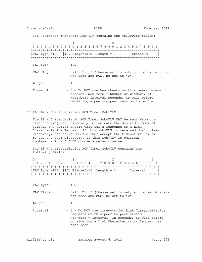
Internet-Draft DLEP February 2012
The Heartbeat Threshold Sub-TLV contains the following fields:
0 1 2 3 0 1 2 3 4 5 6 7 8 9 0 1 2 3 4 5 6 7 8 9 0 1 2 3 4 5 6 7 8 9 0 1 +-+-+-+-+-+-+-+-+-+-+-+-+-+-+-+-+-+-+-+-+-+-+-+-+-+-+-+-+-+-+-+-+ |TLV Type =TBD |TLV Flags=0x10 |Length = 1 | Threshold | +-+-+-+-+-+-+-+-+-+-+-+-+-+-+-+-+-+-+-+-+-+-+-+-+-+-+-+-+-+-+-+-+
TLV Type - TBD
TLV Flags - 0x10, Bit 3 (thasvalue) is set, all other bits are not used and MUST be set to ’0’.
Length - 1
Threshold - 0 = Do NOT use heartbeats on this peer-to-peer session. Non-zero = Number of windows, of Heartbeat Interval seconds, to wait before declaring a peer-to-peer session to be lost.
10.16 Link Characteristics ACK Timer Sub-TLV
The Link Characteristic ACK Timer Sub-TLV MAY be sent from the client during Peer Discovery to indicate the desired number of seconds the server should wait for a response to a Link Characteristics Request. If this sub-TLV is received during Peer Discovery, the server MUST either accept the timeout value, or reject the Peer Discovery. If this Sub-TLV is omitted, implementations SHOULD choose a default value.
The Link Characteristics ACK Timer Sub-TLV contains the following fields:
0 1 2 3 0 1 2 3 4 5 6 7 8 9 0 1 2 3 4 5 6 7 8 9 0 1 2 3 4 5 6 7 8 9 0 1 +-+-+-+-+-+-+-+-+-+-+-+-+-+-+-+-+-+-+-+-+-+-+-+-+-+-+-+-+-+-+-+-+ |TLV Type =TBD |TLV Flags=0x10 |Length = 1 | Interval | +-+-+-+-+-+-+-+-+-+-+-+-+-+-+-+-+-+-+-+-+-+-+-+-+-+-+-+-+-+-+-+-+
TLV Type - TBD
TLV Flags - 0x10, Bit 3 (thasvalue) is set, all other bits are not used and MUST be set to ’0’.
Length - 1
Interval - 0 = Do NOT use timeouts for Link Characteristics requests on this peer-to-peer session. Non-zero = Interval, in seconds, to wait before considering a Link Characteristics Request has been lost.
Ratliff et al. Expires August 6, 2012 [Page 22]

Internet-Draft DLEP February 2012
10.17 Credit Window Status Sub-TLV
The Credit Window Status Sub-TLV MUST be sent by the DLEP peer originating a Neighbor Up message when use of credits is desired for a given session. In the Neighbor Up message, when credits are desired, the originating peer MUST set the value of the window it controls (e.g. the Client Receive Window, or Server Receive Window) to an initial, non-zero value. The peer receiving a Neighbor Up message with a Credit Window Status Sub-TLV MUST either reject the use of credits, via a Neighbor Up ACK response with the correct Status Sub-TLV, or set the initial value from the data contained in the Credit Window Status Sub-TLV. If the initialization completes successfully, the receiving peer MUST respond to the Neighbor Up message with a Neighbor Up ACK message that contains a Credit Window Status Sub-TLV, initializing its receive window.
The Credit Window Status Sub-TLV contains the following fields:
0 1 2 3 0 1 2 3 4 5 6 7 8 9 0 1 2 3 4 5 6 7 8 9 0 1 2 3 4 5 6 7 8 9 0 1 +-+-+-+-+-+-+-+-+-+-+-+-+-+-+-+-+-+-+-+-+-+-+-+-+-+-+-+-+-+-+-+-+ |TLV Type =TBD |TLV Flags=0x10 |Length = 16 | Client Receive| | | | | Window value | +-+-+-+-+-+-+-+-+-+-+-+-+-+-+-+-+-+-+-+-+-+-+-+-+-+-+-+-+-+-+-+-+ | Client Receive Window Value | +-+-+-+-+-+-+-+-+-+-+-+-+-+-+-+-+-+-+-+-+-+-+-+-+-+-+-+-+-+-+-+-+ | Client Receive Window Value | Server Receive| | | Window Value | +-+-+-+-+-+-+-+-+-+-+-+-+-+-+-+-+-+-+-+-+-+-+-+-+-+-+-+-+-+-+-+-+ | Server Receive Window Value | +-+-+-+-+-+-+-+-+-+-+-+-+-+-+-+-+-+-+-+-+-+-+-+-+-+-+-+-+-+-+-+-+ | Server Receive Window Value | +-+-+-+-+-+-+-+-+-+-+-+-+-+-+-+-+-+-+-+-+-+-+-+-+
TLV Type - TBD
TLV Flags - 0x10, Bit 3 (thasvalue) is set, all other bits are not used and MUST be set to ’0’.
Length - 16
Client Receive - A 64-bit unsigned number, indicating the Window value current (or initial) number of credits available on the Client Receive Window.
Server Receive - A 64-bit unsigned number, indicating the Window Value current (or initial) number of credits available on the Server Receive Window.
Ratliff et al. Expires August 6, 2012 [Page 23]

Internet-Draft DLEP February 2012
10.18 Credit Grant Sub-TLV
The Credit Grant Request Sub-TLV MAY be sent from either DLEP peer to grant an increment to credits on a window. The Credit Grant Sub-TLV is sent as part of a Neighbor Update message. The value in a Credit Grant Sub-TLV represents an increment to be added to any existing credits available on the window. Upon successful receipt and processing of a Credit Grant Sub-TLV, the receiving peer SHOULD respond with a DLEP Neighbor Update message containing a Credit Window Status Sub-TLV to report the updated aggregate values for synchronization purposes.
The Credit Grant Sub-TLV contains the following fields:
0 1 2 3 0 1 2 3 4 5 6 7 8 9 0 1 2 3 4 5 6 7 8 9 0 1 2 3 4 5 6 7 8 9 0 1 +-+-+-+-+-+-+-+-+-+-+-+-+-+-+-+-+-+-+-+-+-+-+-+-+-+-+-+-+-+-+-+-+ |TLV Type =TBD |TLV Flags=0x10 |Length = 8 | Credit | | | | | Increment | +-+-+-+-+-+-+-+-+-+-+-+-+-+-+-+-+-+-+-+-+-+-+-+-+-+-+-+-+-+-+-+-+ | Credit Increment | +-+-+-+-+-+-+-+-+-+-+-+-+-+-+-+-+-+-+-+-+-+-+-+-+-+-+-+-+-+-+-+-+ | Credit Increment | +-+-+-+-+-+-+-+-+-+-+-+-+-+-+-+-+-+-+-+-+-+-+-+-+
TLV Type - TBD
TLV Flags - 0x10, Bit 3 (thasvalue) is set, all other bits are not used and MUST be set to ’0’.
Length - 0
Reserved - A 64-bit unsigned number representing the additional credits to be assigned to the credit window. Since credits can only be granted by the receiver on a window, the applicable credit window (either the CRW or the SRW) is derived from the sender of the grant. The Credit Increment MUST NOT cause the window to overflow; if this condition occurs, implementations MUST set the credit window to the maximum value contained in a 64-bit quantity.
10.19 Credit Request Sub-TLV
The Credit Request Sub-TLV MAY be sent from either DLEP peer, via a Neighbor Update order, to indicate the desire for the partner to grant additional credits in order for data transfer to proceed on the session. If the corresponding Neighbor Up message for this session did NOT contain a Credit Window Status Sub-TLV, indicating that credits are to be used on the session, then the Credit Request Sub-TLV MUST be rejected, by sending a Neighbor Update ACK containing a Status Sub-TLV, by the receiving peer. If credits are in use on
Ratliff et al. Expires August 6, 2012 [Page 24]

Internet-Draft DLEP February 2012
the session, then the receiving peer MAY respond with a DLEP Neighbor Update message containing a Credit Grant Sub-TLV with an increment of credits for the session.
The Credit Request Sub-TLV contains the following fields:
0 1 2 3 0 1 2 3 4 5 6 7 8 9 0 1 2 3 4 5 6 7 8 9 0 1 2 3 4 5 6 7 8 9 0 1 +-+-+-+-+-+-+-+-+-+-+-+-+-+-+-+-+-+-+-+-+-+-+-+-+-+-+-+-+-+-+-+-+ |TLV Type =TBD |TLV Flags=0x10 |Length = 0 | Reserved, MUST| | | | | be set to 0 | +-+-+-+-+-+-+-+-+-+-+-+-+-+-+-+-+-+-+-+-+-+-+-+-+-+-+-+-+-+-+-+-+
TLV Type - TBD
TLV Flags - 0x10, Bit 3 (thasvalue) is set, all other bits are not used and MUST be set to ’0’.
Length - 0
Reserved - 0 = This field is currently unused and MUST be set to 0.
11. DLEP Protocol Messages
DLEP places no additional requirements on the RFC 5444 Packet formats, or the packet header. DLEP does require that the optional ’msg-seq-num’ in the message header exist, and defines a set of values for the ’tlv-type’ field in the RFC 5444 TLV block. Therefore, a DLEP message, starting from the RFC 5444 Message header, would appear as follows:
0 1 2 3 0 1 2 3 4 5 6 7 8 9 0 1 2 3 4 5 6 7 8 9 0 1 2 3 4 5 6 7 8 9 0 1 +-+-+-+-+-+-+-+-+-+-+-+-+-+-+-+-+-+-+-+-+-+-+-+-+-+-+-+-+-+-+-+-+ | Msg Type = |Msg Flg|AddrLen| Message Size | | DLEP_MESSAGE | 0x1 | 0x0 | | | (value TBD) | | | | +-+-+-+-+-+-+-+-+-+-+-+-+-+-+-+-+-+-+-+-+-+-+-+-+-+-+-+-+-+-+-+-+ | Message Seq Num | TLV block length (length of | | | DLEP order + Sub-TLVs) | +-+-+-+-+-+-+-+-+-+-+-+-+-+-+-+-+-+-+-+-+-+-+-+-+-+-+-+-+-+-+-+-+ | DLEP Message |TLV Flags=0x10 | Length | Start of DLEP | | Block value | | | Sub-TLVs... | +-+-+-+-+-+-+-+-+-+-+-+-+-+-+-+-+-+-+-+-+-+-+-+-+-+-+-+-+-+-+-+-+
11.1 Message Block TLV Values
As mentioned above, all DLEP messages utilize a single RFC 5444 message type, the DLEP_MESSAGE (TBD). DLEP further identifies protocol messages by using the ’tlv-type’ field in the RFC 5444 message TLV block. DLEP defines the following Message-Type- specific values for the tlv-type field:
Ratliff et al. Expires August 6, 2012 [Page 25]

Internet-Draft DLEP February 2012
TLV TLV Value Description ========================================= TBD Attached Peer Discovery TBD Detached Peer Discovery TBD Peer Offer TBD Peer Update TBD Peer Update ACK TBD Peer Termination TBD Peer Termination ACK TBD Neighbor Up TBD Neighbor Up ACK TBD Neighbor Down TBD Neighbor Down ACK TBD Neighbor Update TBD Neighbor Address Update TBD Neighbor Address Update ACK TBD Heartbeat TBD Link Characteristics Request TBD Link Characteristics ACK
In all of the diagrams following, the message layouts begin with the RFC 5444 message header.
12. Peer Discovery Messages
There are two different types of Peer Discovery Messages, Attached and Detached. Attached Peer Discovery Messages are sent by the client when it is directly attached to the server (e.g. the client exists as a card in the chassis, or it is connected via Ethernet with no intervening devices). The Detached Peer Discovery message, on the other hand, is sent by a "remote" client -- for example, a client at a satellite hub system might use a Detached Discovery Message in order to act as a proxy for remote ground terminals. To explain in another way, a detached client uses the variable link itself (the radio or satellite link) to establish a DLEP session with a remote server.
12.1 Attached Peer Discovery Message
The Attached Peer Discovery Message is sent by an attached client to a server to begin a new DLEP association. The Peer Offer message is required to complete the discovery process. The client MAY implement its own retry heuristics in the event it (the client) determines the Attached Peer Discovery Message has timed out. An Attached Peer Discovery Message received from a peer that is already in session MUST be processed as if a Peer Termination Message had been received. An implementation MAY then process the received Attached Peer Discovery Message.
Note that metric Sub-TLVs MAY be supplied with the Peer Discovery order. If metric Sub-TLVs are supplied, they MUST be used as a default value for all neighbor sessions established via this peer.
Ratliff et al. Expires August 6, 2012 [Page 26]

Internet-Draft DLEP February 2012
The Attached Peer Discovery Message contains the following fields:
0 1 2 3 0 1 2 3 4 5 6 7 8 9 0 1 2 3 4 5 6 7 8 9 0 1 2 3 4 5 6 7 8 9 0 1 +-+-+-+-+-+-+-+-+-+-+-+-+-+-+-+-+-+-+-+-+-+-+-+-+-+-+-+-+-+-+-+-+ | Msg Type = |Msg Flg|AddrLen| Message Size | | DLEP_MESSAGE | 0x1 | 0x0 | 22 + size of opt | | (value TBD) | | | sub-TLV | +-+-+-+-+-+-+-+-+-+-+-+-+-+-+-+-+-+-+-+-+-+-+-+-+-+-+-+-+-+-+-+-+ | Message Seq Num |TLVs Length =14 + opt sub-TLVs | +-+-+-+-+-+-+-+-+-+-+-+-+-+-+-+-+-+-+-+-+-+-+-+-+-+-+-+-+-+-+-+-+ | DLEP Attached |TLV Flags=0x10 | Length =11 + | Sub-TLVs | | Peer Discovery| | opt sub-TLVs | as noted below| | (Value TDB) | | | | +-+-+-+-+-+-+-+-+-+-+-+-+-+-+-+-+-+-+-+-+-+-+-+-+-+-+-+-+-+-+-+-+
Message Type - DLEP_MESSAGE (value TBD)
Message Flags - Set to 0x1 (bit 3, mhasseqnum bit is set). No other bits are used and MUST be set to ’0’.
Message Address Length - 0x0
Message Size - 22 + size of optional sub-TLVs
Message Sequence Number - A 16-bit unsigned integer field containing a sequence number generated by the message originator.
TLV Block - TLVs Length: 14 + size of optional sub-TLVs.
Sub-TLVs: Identification (MANDATORY) Version (OPTIONAL) Peer Type (OPTIONAL) Heartbeat Interval (OPTIONAL) Heartbeat Threshold (OPTIONAL) Link Characteristics ACK Timer (OPTIONAL) Maximum Data Rate (OPTIONAL) Current Data Rate (OPTIONAL) Latency (OPTIONAL) Expected Forwarding Time (OPTIONAL) Resources (OPTIONAL) Relative Link Quality (OPTIONAL)
12.2 Detached Peer Discovery Message
The Detached Peer Discovery Message is sent by a detached client proxy to a server to begin a new DLEP session. The Peer Offer message is required to complete the discovery process. The client
Ratliff et al. Expires August 6, 2012 [Page 27]
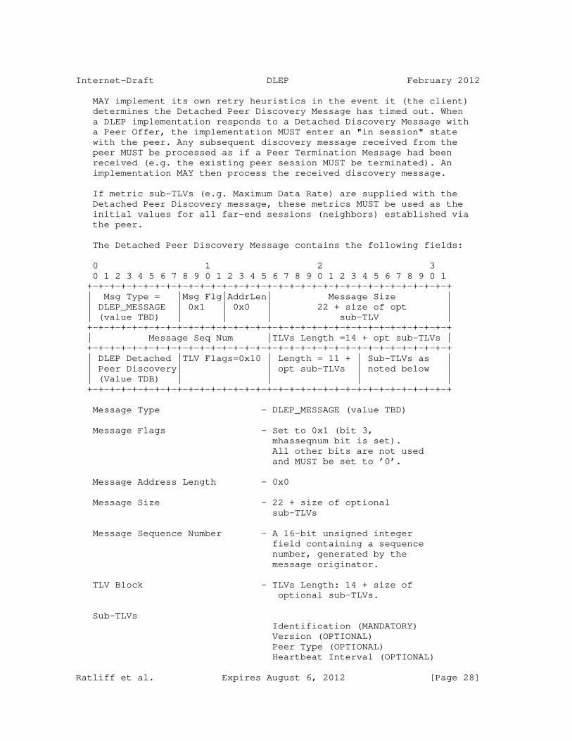
Internet-Draft DLEP February 2012
MAY implement its own retry heuristics in the event it (the client) determines the Detached Peer Discovery Message has timed out. When a DLEP implementation responds to a Detached Discovery Message with a Peer Offer, the implementation MUST enter an "in session" state with the peer. Any subsequent discovery message received from the peer MUST be processed as if a Peer Termination Message had been received (e.g. the existing peer session MUST be terminated). An implementation MAY then process the received discovery message.
If metric sub-TLVs (e.g. Maximum Data Rate) are supplied with the Detached Peer Discovery message, these metrics MUST be used as the initial values for all far-end sessions (neighbors) established via the peer.
The Detached Peer Discovery Message contains the following fields:
0 1 2 3 0 1 2 3 4 5 6 7 8 9 0 1 2 3 4 5 6 7 8 9 0 1 2 3 4 5 6 7 8 9 0 1 +-+-+-+-+-+-+-+-+-+-+-+-+-+-+-+-+-+-+-+-+-+-+-+-+-+-+-+-+-+-+-+-+ | Msg Type = |Msg Flg|AddrLen| Message Size | | DLEP_MESSAGE | 0x1 | 0x0 | 22 + size of opt | | (value TBD) | | | sub-TLV | +-+-+-+-+-+-+-+-+-+-+-+-+-+-+-+-+-+-+-+-+-+-+-+-+-+-+-+-+-+-+-+-+ | Message Seq Num |TLVs Length =14 + opt sub-TLVs | +-+-+-+-+-+-+-+-+-+-+-+-+-+-+-+-+-+-+-+-+-+-+-+-+-+-+-+-+-+-+-+-+ | DLEP Detached |TLV Flags=0x10 | Length = 11 + | Sub-TLVs as | | Peer Discovery| | opt sub-TLVs | noted below | | (Value TDB) | | | | +-+-+-+-+-+-+-+-+-+-+-+-+-+-+-+-+-+-+-+-+-+-+-+-+-+-+-+-+-+-+-+-+
Message Type - DLEP_MESSAGE (value TBD)
Message Flags - Set to 0x1 (bit 3, mhasseqnum bit is set). All other bits are not used and MUST be set to ’0’.
Message Address Length - 0x0
Message Size - 22 + size of optional sub-TLVs
Message Sequence Number - A 16-bit unsigned integer field containing a sequence number, generated by the message originator.
TLV Block - TLVs Length: 14 + size of optional sub-TLVs.
Sub-TLVs Identification (MANDATORY) Version (OPTIONAL) Peer Type (OPTIONAL) Heartbeat Interval (OPTIONAL)
Ratliff et al. Expires August 6, 2012 [Page 28]

Internet-Draft DLEP February 2012
Heartbeat Threshold (OPTIONAL) Link Char. ACK Timer (OPTIONAL) Maximum Data Rate (OPTIONAL) Current Data Rate (OPTIONAL) Latency (OPTIONAL) Expected Forwarding Time (OPTIONAL) Resources (OPTIONAL) Relative Link Quality (OPTIONAL)
As in the Attached Peer Discovery, the client MAY include metric sub-TLVs. If included, the router SHOULD use these values as defaults that will apply to all sessions established via this client.
13. Peer Offer Message
The Peer Offer Message is sent by a server to a client in response to a Peer Discovery Message. The Peer Offer Message is the response to either of the Peer Discovery messages (Attached or Detached), and completes the DLEP peer session establishment. Upon sending the Peer Offer Message, the server then enters an "in session" state with the client. From the client perspective, receipt and successful parsing of a Peer Offer order MUST cause the client to enter the "in session" state. Any subsequent Discovery messages sent or received on this session MUST be considered an error, and the session MUST be terminated as if a Peer Termination Message had been received.
The Peer Offer Message contains the following fields:
0 1 2 3 0 1 2 3 4 5 6 7 8 9 0 1 2 3 4 5 6 7 8 9 0 1 2 3 4 5 6 7 8 9 0 1 +-+-+-+-+-+-+-+-+-+-+-+-+-+-+-+-+-+-+-+-+-+-+-+-+-+-+-+-+-+-+-+-+ | Msg Type = |Msg Flg|AddrLen| Message Size | | DLEP_MESSAGE | 0x1 | 0x0 | 22 + size of opt | | (value TBD) | | | sub-TLV | +-+-+-+-+-+-+-+-+-+-+-+-+-+-+-+-+-+-+-+-+-+-+-+-+-+-+-+-+-+-+-+-+ | Message Seq Num |TLVs Length =14 + opt sub-TLVs | +-+-+-+-+-+-+-+-+-+-+-+-+-+-+-+-+-+-+-+-+-+-+-+-+-+-+-+-+-+-+-+-+ |DLEP Peer Offer|TLV Flags=0x10 | Length = 11 + | Sub-TLVs as | | (Value TBD) | | opt sub-TLVs | indicated | | | | | below | +-+-+-+-+-+-+-+-+-+-+-+-+-+-+-+-+-+-+-+-+-+-+-+-+-+-+-+-+-+-+-+-+
Message Type - DLEP_MESSAGE (Value TBD)
Message Flags - Set to 0x1 (bit 3, mhasseqnum bit is set). All other bits are unused and MUST be set to ’0’.
Message Address Length - 0x0
Message Size - 22 + size of optional sub-TLVs
Message Sequence Number - A 16-bit unsigned integer field containing a sequence number, generated by the message originator.Ratliff et al. Expires August 6, 2012 [Page 29]

Internet-Draft DLEP February 2012
TLV Block - TLV Length: 14 + size of optional sub-TLVs
Sub TLVs Identification (MANDATORY) Version (OPTIONAL) Peer Type (OPTIONAL) IPv4 Address (OPTIONAL) IPv6 Address (OPTIONAL) Status (OPTIONAL) Heartbeat Interval (OPTIONAL) Heartbeat Threshold (OPTIONAL) Link Characteristics ACK Timer (OPTIONAL)
14. Peer Update Message
The Peer Update message is sent by a DLEP peer to indicate local Layer 3 address changes, or for metric changes on a device-wide basis. For example, addition of an IPv4 address to the server would prompt a Peer Update message to its attached DLEP clients. Also, a client that changes its Maximum Data Rate for all destinations MAY reflect that change via a Peer Update Message to its attached server.
With Layer 3 address changes, if the client is capable of understanding and forwarding this information, the address update would prompt any remote DLEP clients (DLEP clients that are on the far-end of the variable link) to issue a "Neighbor Update" message to their local servers with the new (or deleted) addresses. Clients that do not track Layer 3 addresses MUST silently parse and ignore the Peer Update Message. Clients that track Layer 3 addresses MUST acknowledge the Peer Update with a Peer Update ACK message. Servers receiving a Peer Update with metric changes MUST apply the new metric to all neighbor sessions established via the client. Peers MAY employ heuristics to retransmit Peer Update messages. The sending of Peer Update Messages for Layer 3 address changes SHOULD cease when a server implementation determines that a client does NOT support Layer 3 address tracking.
If metric Sub-TLVs are supplied with the Peer Update message (e.g. Maximum Data Rate), these metrics MUST be applied to all neighbor sessions accessible via the peer.
The Peer Update Message contains the following fields:
0 1 2 3 0 1 2 3 4 5 6 7 8 9 0 1 2 3 4 5 6 7 8 9 0 1 2 3 4 5 6 7 8 9 0 1 +-+-+-+-+-+-+-+-+-+-+-+-+-+-+-+-+-+-+-+-+-+-+-+-+-+-+-+-+-+-+-+-+ | Msg Type = |Msg Flg|AddrLen| Message Size | | DLEP_MESSAGE | 0x1 | 0x0 | 22 + size of opt | | (value TBD) | | | sub-TLVs | +-+-+-+-+-+-+-+-+-+-+-+-+-+-+-+-+-+-+-+-+-+-+-+-+-+-+-+-+-+-+-+-+ | Message Seq Num |TLVs Length =14 + opt sub-TLVs | +-+-+-+-+-+-+-+-+-+-+-+-+-+-+-+-+-+-+-+-+-+-+-+-+-+-+-+-+-+-+-+-+ | DLEP Peer |TLV Flags=0x10 | Length = 11 + | Sub-TLVs as | | Update | | opt sub-TLVs | noted below | | (Value TDB) | | | | +-+-+-+-+-+-+-+-+-+-+-+-+-+-+-+-+-+-+-+-+-+-+-+-+-+-+-+-+-+-+-+-+Ratliff et al. Expires August 6, 2012 [Page 30]

Internet-Draft DLEP February 2012
Message Type - DLEP_MESSAGE (Value TBD)
Message Flags - Set to 0x1 (bit 3, mhasseqnum bit is set). All other bits are unused and MUST be set to ’0’.
Message Address Length - 0x0
Message Size - 22 + optional Sub-TLVs
Message Sequence Number - A 16-bit unsigned integer containing a sequence number (generated by originator).
TLV Block - TLV Length: 14 + length of optional sub-TLVs. Sub TLVs Identification (MANDATORY) IPv4 Address (OPTIONAL) IPv6 Address (OPTIONAL) Maximum Data Rate (OPTIONAL) Current Data Rate (OPTIONAL) Latency (OPTIONAL) Expected Forwarding Time (OPTIONAL) Resources (OPTIONAL) Relative Link Quality (OPTIONAL)
15. Peer Update ACK Message
A peer sends the Peer Update ACK Message to indicate whether a Peer Update Message was successfully processed.
The Peer Update ACK message contains the following fields:
0 1 2 3 0 1 2 3 4 5 6 7 8 9 0 1 2 3 4 5 6 7 8 9 0 1 2 3 4 5 6 7 8 9 0 1 +-+-+-+-+-+-+-+-+-+-+-+-+-+-+-+-+-+-+-+-+-+-+-+-+-+-+-+-+-+-+-+-+ | Msg Type = |Msg Flg|AddrLen| Message Size | | DLEP_MESSAGE | 0x1 | 0x0 | 22 + size of opt | | (value TBD) | | | sub-TLVs | +-+-+-+-+-+-+-+-+-+-+-+-+-+-+-+-+-+-+-+-+-+-+-+-+-+-+-+-+-+-+-+-+ | Message Seq Num |TLVs Length =14 + opt sub-TLVs | +-+-+-+-+-+-+-+-+-+-+-+-+-+-+-+-+-+-+-+-+-+-+-+-+-+-+-+-+-+-+-+-+ | DLEP Peer |TLV Flags=0x10 | Length = 11 + | Sub-TLVs as | | Update ACK | | opt sub-TLVs | noted below | | (Value TDB) | | | | +-+-+-+-+-+-+-+-+-+-+-+-+-+-+-+-+-+-+-+-+-+-+-+-+-+-+-+-+-+-+-+-+
Message Type - DLEP_MESSAGE (Value TBD)
Message Flags - Set to 0x1 (bit 3, mhasseqnum bit is set). All other bits are unused and MUST be set to ’0’.
Message Address Length - 0x0
Ratliff et al. Expires August 6, 2012 [Page 31]

Internet-Draft DLEP February 2012
Message Size - 22 + size of optional sub-TLVs.
Message Sequence Number - A 16-bit unsigned integer field containing the sequence number from the Neighbor Up Message that is being acknowledged.
TLV Block - TLV Length: 14 + optional sub-TLVs
Sub TLVs Identification (MANDATORY) Status (OPTIONAL)
16. Peer Termination Message
The Peer Termination Message is sent by either the client or the server when a session needs to be terminated. Transmission of a Peer Termination ACK message is required to confirm the termination process. The sender of the Peer Termination message is free to define its heuristics in event of a timeout. The receiver of a Peer Termination Message MUST terminate all neighbor sessions and release associated resources. State machines are returned to the "discovery" state. No Neighbor Down messages are sent.
The Peer Termination Message contains the following fields:
0 1 2 3 0 1 2 3 4 5 6 7 8 9 0 1 2 3 4 5 6 7 8 9 0 1 2 3 4 5 6 7 8 9 0 1 +-+-+-+-+-+-+-+-+-+-+-+-+-+-+-+-+-+-+-+-+-+-+-+-+-+-+-+-+-+-+-+-+ | Msg Type = |Msg Flg|AddrLen| Message Size | | DLEP_MESSAGE | 0x1 | 0x0 | 22 + size of opt | | (value TBD) | | | sub-TLVs | +-+-+-+-+-+-+-+-+-+-+-+-+-+-+-+-+-+-+-+-+-+-+-+-+-+-+-+-+-+-+-+-+ | Message Seq Num |TLVs Length =14 + opt sub-TLVs | +-+-+-+-+-+-+-+-+-+-+-+-+-+-+-+-+-+-+-+-+-+-+-+-+-+-+-+-+-+-+-+-+ | DLEP Peer |TLV Flags=0x10 | Length = 11 + | Sub-TLVs as | | Termination | | opt sub-TLVs | noted below | | (Value TDB) | | | | +-+-+-+-+-+-+-+-+-+-+-+-+-+-+-+-+-+-+-+-+-+-+-+-+-+-+-+-+-+-+-+-+
Message Type - DLEP_MESSAGE (Value TBD)
Message Flags - Set to 0x1 (bit 3, mhasseqnum bit is set). All other bits are unused and MUST be set to ’0’.
Message Address Length - 0x0
Message Size - 22 + size of optional sub-TLVs.
Message Sequence Number - A 16-bit unsigned integer field containing a sequence number generated by the message originator.
Ratliff et al. Expires August 6, 2012 [Page 32]

Internet-Draft DLEP February 2012
TLV Block - TLV Length = 14 + optional sub-TLVs
Sub TLVs Identification (MANDATORY) Status (OPTIONAL)
17. Peer Termination ACK Message
The Peer Termination Message ACK is sent by a DLEP peer in response to a received Peer Termination order.
The Peer Termination ACK Message contains the following fields:
0 1 2 3 0 1 2 3 4 5 6 7 8 9 0 1 2 3 4 5 6 7 8 9 0 1 2 3 4 5 6 7 8 9 0 1 +-+-+-+-+-+-+-+-+-+-+-+-+-+-+-+-+-+-+-+-+-+-+-+-+-+-+-+-+-+-+-+-+ | Msg Type = |Msg Flg|AddrLen| Message Size | | DLEP_MESSAGE | 0x1 | 0x0 | 22 + size of opt | | (value TBD) | | | sub-TLVs | +-+-+-+-+-+-+-+-+-+-+-+-+-+-+-+-+-+-+-+-+-+-+-+-+-+-+-+-+-+-+-+-+ | Message Seq Num |TLVs Length =14 + opt sub-TLVs | +-+-+-+-+-+-+-+-+-+-+-+-+-+-+-+-+-+-+-+-+-+-+-+-+-+-+-+-+-+-+-+-+ | DLEP Peer Term|TLV Flags=0x10 | Length = 11 + | Sub-TLVs as | | ACK | | opt sub-TLVs | noted below | | (Value TBD) | | | | +-+-+-+-+-+-+-+-+-+-+-+-+-+-+-+-+-+-+-+-+-+-+-+-+-+-+-+-+-+-+-+-+
Message Type - DLEP_MESSAGE (Value TBD)
Message Flags - Set to 0x1 (bit 3, mhasseqnum bit is set). All other bits are unused and MUST be set to ’0’.
Message Address Length - 0x0
Message Size - 22 + optional sub-TLVs.
Message Sequence Number - A 16-bit unsigned integer field containing the sequence number in the corresponding Peer Termination Message being acknowledged.
TLV Block - TLV Length = 14 + optional Sub-TLVs
Sub-TLVs Identification (MANDATORY) Status (OPTIONAL)
18. Neighbor Up Message
A peer sends the Neighbor Up message to report that a new potential routing neighbor, or a new destination within the network, has been detected. A Neighbor Up ACK Message is required
to confirm a received Neighbor Up. A Neighbor Up message can be sent by a client to signal that it (the client) has detected a new

Ratliff et al. Expires August 6, 2012 [Page 33]

Internet-Draft DLEP February 2012
neighbor, or by the server to indicate that new destinations (e.g. Multicast groups) exist within the network.
The sender of the Neighbor Up Message is free to define its retry heuristics in event of a timeout. When a Neighbor Up message is received and successfully parsed, the receiver should enter an "in session" state with regard to the far-end destination, and send an acknowledgement to the originating peer.
The Neighbor Up Message contains the following fields:
0 1 2 3 0 1 2 3 4 5 6 7 8 9 0 1 2 3 4 5 6 7 8 9 0 1 2 3 4 5 6 7 8 9 0 1 +-+-+-+-+-+-+-+-+-+-+-+-+-+-+-+-+-+-+-+-+-+-+-+-+-+-+-+-+-+-+-+-+ | Msg Type = |Msg Flg|AddrLen| Message Size | | DLEP_MESSAGE | 0x1 | 0x0 | 31 + size of opt | | (value TBD) | | | sub-TLVs | +-+-+-+-+-+-+-+-+-+-+-+-+-+-+-+-+-+-+-+-+-+-+-+-+-+-+-+-+-+-+-+-+ | Message Seq Num |TLVs Length =23 + opt sub-TLVs | +-+-+-+-+-+-+-+-+-+-+-+-+-+-+-+-+-+-+-+-+-+-+-+-+-+-+-+-+-+-+-+-+ | DLEP Neighbor |TLV Flags=0x10 | Length =20 + | Sub-TLVs as | | Up (TBD) | | opt sub-TLVs | noted below | | | | | | +-+-+-+-+-+-+-+-+-+-+-+-+-+-+-+-+-+-+-+-+-+-+-+-+-+-+-+-+-+-+-+-+
Message Type - DLEP_MESSAGE (Value TBD)
Message Flags - Set to 0x1 (bit 3, mhasseqnum bit is set). All other bits are unused and MUST be set to ’0’.
Message Address Length - 0x0
Message Size - 31 + optional Sub-TLVs
Message Sequence Number - A 16-bit unsigned integer field containing a sequence number generated by the message originator.
TLV Block - TLV Length: 23 + optional Sub-TLVs.
Sub-TLVs Identification (MANDATORY) MAC Address (MANDATORY) IPv4 Address (OPTIONAL) IPv6 Address (OPTIONAL) Maximum Data Rate (OPTIONAL) Current Data Rate (OPTIONAL) Latency (OPTIONAL) Expected Forwarding Time (OPTIONAL) Resources (OPTIONAL) Relative Link Factor (OPTIONAL) Credit Window Status (OPTIONAL)
Ratliff et al. Expires August 6, 2012 [Page 34]

Internet-Draft DLEP February 2012
19. Neighbor Up ACK Message
A peer sends the Neighbor Up ACK Message to indicate whether a Neighbor Up Message was successfully processed. When a peer receives a Neighbor Up ACK message containing a Status Sub-TLV with a status code of 0, the receiving peer should enter an "in session" state with respect to the far-end destination.
The Neighbor Up ACK message contains the following fields:
0 1 2 3 0 1 2 3 4 5 6 7 8 9 0 1 2 3 4 5 6 7 8 9 0 1 2 3 4 5 6 7 8 9 0 1 +-+-+-+-+-+-+-+-+-+-+-+-+-+-+-+-+-+-+-+-+-+-+-+-+-+-+-+-+-+-+-+-+ | Msg Type = |Msg Flg|AddrLen| Message Size | | DLEP_MESSAGE | 0x1 | 0x0 | 35 | | (value TBD) | | | | +-+-+-+-+-+-+-+-+-+-+-+-+-+-+-+-+-+-+-+-+-+-+-+-+-+-+-+-+-+-+-+-+ | Message Seq Num |TLVs Length = 27 | +-+-+-+-+-+-+-+-+-+-+-+-+-+-+-+-+-+-+-+-+-+-+-+-+-+-+-+-+-+-+-+-+ | DLEP Neighbor |TLV Flags=0x10 | Length = 24 | Sub-TLVs as | | Up ACK (TBD) | | | noted below | +-+-+-+-+-+-+-+-+-+-+-+-+-+-+-+-+-+-+-+-+-+-+-+-+-+-+-+-+-+-+-+-+
Message Type - DLEP_MESSAGE (Value TBD)
Message Flags - Set to 0x1 (bit 3, mhasseqnum bit is set). All other bits are unused and MUST be set to ’0’.
Message Address Length - 0x0
Message Size - 35
Message Sequence Number - A 16-bit unsigned integer field containing the sequence number from the Neighbor Down Message that is being acknowledged.
TLV Block - TLV Length: 27
Sub-TLVs - Identification (MANDATORY) MAC Address Sub-TLV (MANDATORY) Status Sub-TLV (MANDATORY) Credit Window Status (OPTIONAL)
20. Neighbor Down Message
A DLEP peer sends the Neighbor Down message to report when a destination (a routing peer or a multicast group) is no longer reachable. The Neighbor Down message MUST contain a MAC Address TLV. Any other TLVs present MAY be ignored. A Neighbor Down ACK Message is required to confirm the process. The sender of the Neighbor Down message is free to define its retry heuristics in event of a timeout. Upon successful receipt and parsing of a Neighbor Down message, the
Ratliff et al. Expires August 6, 2012 [Page 35]

Internet-Draft DLEP February 2012
receiving peer MUST remove all state information for the destination, and send a Neighbor Down ACK message to the originating peer.
The Neighbor Down Message contains the following fields:
0 1 2 3 0 1 2 3 4 5 6 7 8 9 0 1 2 3 4 5 6 7 8 9 0 1 2 3 4 5 6 7 8 9 0 1 +-+-+-+-+-+-+-+-+-+-+-+-+-+-+-+-+-+-+-+-+-+-+-+-+-+-+-+-+-+-+-+-+ | Msg Type = |Msg Flg|AddrLen| Message Size | | DLEP_MESSAGE | 0x1 | 0x0 | 31 + optional | | (value TBD) | | | sub-TLV | +-+-+-+-+-+-+-+-+-+-+-+-+-+-+-+-+-+-+-+-+-+-+-+-+-+-+-+-+-+-+-+-+ | Message Seq Num | TLVs Length = 23 + optional | | | Sub-TLV | +-+-+-+-+-+-+-+-+-+-+-+-+-+-+-+-+-+-+-+-+-+-+-+-+-+-+-+-+-+-+-+-+ | TLV Type = |TLV Flags=0x10 | Length = 20 + | Sub-TLVs as | | DLEP Neighbor | | optional Sub- | noted below | | Down (TBD) | | TLV | | +-+-+-+-+-+-+-+-+-+-+-+-+-+-+-+-+-+-+-+-+-+-+-+-+-+-+-+-+-+-+-+-+
Message Type - DLEP_MESSAGE (Value TBD)
Message Flags - Set to 0x1 (bit 3, mhasseqnum bit is set). All other bits are unused and MUST be set to ’0’.
Message Address Length - 0x0
Message Size - 31 + optional TLVs
Message Sequence Number - A 16-bit unsigned integer field containing a sequence number generated by the message originator.
TLV Block - TLV Length: 23 + optional Sub-TLVs
Sub TLVs Identification (MANDATORY) MAC Address (MANDATORY) Status (OPTIONAL)
21. Neighbor Down ACK Message
A peer sends the Neighbor Down ACK Message to indicate whether a received Neighbor Down Message was successfully processed. If successfully processed, the sending peer MUST remove all state information on the referenced neighbor session.
Ratliff et al. Expires August 6, 2012 [Page 36]

Internet-Draft DLEP February 2012
The Neighbor Down ACK message contains the following fields:
0 1 2 3 0 1 2 3 4 5 6 7 8 9 0 1 2 3 4 5 6 7 8 9 0 1 2 3 4 5 6 7 8 9 0 1 +-+-+-+-+-+-+-+-+-+-+-+-+-+-+-+-+-+-+-+-+-+-+-+-+-+-+-+-+-+-+-+-+ | Msg Type = |Msg Flg|AddrLen| Message Size | | DLEP_MESSAGE | 0x1 | 0x0 | 35 | | (value TBD) | | | | +-+-+-+-+-+-+-+-+-+-+-+-+-+-+-+-+-+-+-+-+-+-+-+-+-+-+-+-+-+-+-+-+ | Message Seq Num |TLVs Length = 27 | +-+-+-+-+-+-+-+-+-+-+-+-+-+-+-+-+-+-+-+-+-+-+-+-+-+-+-+-+-+-+-+-+ | DLEP Neighbor |TLV Flags=0x10 | Length = 24 | Sub-TLVs as | | Down ACK (TBD)| | | noted below | +-+-+-+-+-+-+-+-+-+-+-+-+-+-+-+-+-+-+-+-+-+-+-+-+-+-+-+-+-+-+-+-+
Message Type - DLEP_MESSAGE (Value TBD)
Message Flags - Set to 0x1 (bit 3, mhasseqnum bit is set). All other bits are unused and MUST be set to ’0’.
Message Address Length - 0x0
Message Size - 35
Message Sequence Number - A 16-bit unsigned integer field containing the sequence number from the Neighbor Down Message that is being acknowledged.
TLV Block - TLV Length: 27
Sub-TLVs - Identification (MANDATORY) MAC Address (MANDATORY) Status (MANDATORY)
22. Neighbor Update Message
The client sends the Neighbor Update message when a change in link metric parameters is detected for a destination.
The Neighbor Update Message contains the following fields:
0 1 2 3 0 1 2 3 4 5 6 7 8 9 0 1 2 3 4 5 6 7 8 9 0 1 2 3 4 5 6 7 8 9 0 1 +-+-+-+-+-+-+-+-+-+-+-+-+-+-+-+-+-+-+-+-+-+-+-+-+-+-+-+-+-+-+-+-+ | Msg Type = |Msg Flg|AddrLen| Message Size | | DLEP_MESSAGE | 0x1 | 0x0 | 31 + optional | | (value TBD) | | | sub-TLV | +-+-+-+-+-+-+-+-+-+-+-+-+-+-+-+-+-+-+-+-+-+-+-+-+-+-+-+-+-+-+-+-+ | Message Seq Num | TLVs Length = 23 + optional | | | Sub-TLVs | +-+-+-+-+-+-+-+-+-+-+-+-+-+-+-+-+-+-+-+-+-+-+-+-+-+-+-+-+-+-+-+-+ |TLV Type = |TLV Flags=0x10 |Length = 20 + |Sub-TLVs as | |DLEP Neighbor | |optional Sub- |noted below | |Update (TBD) | |TLVs | | +-+-+-+-+-+-+-+-+-+-+-+-+-+-+-+-+-+-+-+-+-+-+-+-+-+-+-+-+-+-+-+-+Ratliff et al. Expires August 6, 2012 [Page 37]

Internet-Draft DLEP February 2012
Message Type - DLEP_MESSAGE (Value TBD)
Message Flags - Set to 0x1 (bit 3, mhasseqnum bit is set). All other bits are unused and MUST be set to ’0’.
Message Address Length - 0x0
Message Size - 31 + optional TLVs
Message Sequence Number - A 16-bit unsigned integer field containing a sequence number, generated by the message originator.
TLV Block - TLVs Length - 23 + optional Sub-TLVs.
Sub TLVs Identification (MANDATORY) MAC Address (MANDATORY) Maximum Data Rate (OPTIONAL) Current Data Rate (OPTIONAL) Latency (OPTIONAL) Resources (OPTIONAL) Relative Link Quality (OPTIONAL) Credit Window Status (OPTIONAL) Credit Grant (OPTIONAL) Credit Request (OPTIONAL)
23. Neighbor Address Update Message
The client sends the Neighbor Address Update message when a change in Layer 3 addressing is detected for a neighbor session.
The Neighbor Address Update Message contains the following fields:
0 1 2 3 0 1 2 3 4 5 6 7 8 9 0 1 2 3 4 5 6 7 8 9 0 1 2 3 4 5 6 7 8 9 0 1 +-+-+-+-+-+-+-+-+-+-+-+-+-+-+-+-+-+-+-+-+-+-+-+-+-+-+-+-+-+-+-+-+ | Msg Type = |Msg Flg|AddrLen| Message Size | | DLEP_MESSAGE | 0x1 | 0x0 | 31 + size of opt | | (value TBD) | | | sub-TLVs | +-+-+-+-+-+-+-+-+-+-+-+-+-+-+-+-+-+-+-+-+-+-+-+-+-+-+-+-+-+-+-+-+ | Message Seq Num |TLVs Length =23 + opt sub-TLVs | +-+-+-+-+-+-+-+-+-+-+-+-+-+-+-+-+-+-+-+-+-+-+-+-+-+-+-+-+-+-+-+-+ | DLEP Neighbor |TLV Flags=0x10 | Length =20 + | Sub-TLVs as | | Address Update| | opt sub-TLVs | noted below | |(TBD) | | | | +-+-+-+-+-+-+-+-+-+-+-+-+-+-+-+-+-+-+-+-+-+-+-+-+-+-+-+-+-+-+-+-+
Message Type - DLEP_MESSAGE (Value TBD)
Message Flags - Set to 0x1 (bit 3, mhasseqnum bit is set). All other bits are unused and MUST be set to ’0’.
Ratliff et al. Expires August 6, 2012 [Page 38]

Internet-Draft DLEP February 2012
Message Address Length - 0x0
Message Size - 31 + optional TLVs
Message Sequence Number - A 16-bit unsigned integer field containing a sequence number, generated by the message originator.
TLV Block - TLVs Length - 23 + optional Sub-TLVs. Sub TLVs Identification Sub-TLV (MANDATORY) MAC Address Sub-TLV (MANDATORY) IPv4 Address Sub-TLV (OPTIONAL) IPv6 Address Sub-TLV (OPTIONAL)
24. Neighbor Address Update ACK Message
The server sends the Neighbor Address Update ACK Message to indicate whether a Neighbor Address Update Message was successfully processed.
The Neighbor Address Update ACK message contains the following fields:
0 1 2 3 0 1 2 3 4 5 6 7 8 9 0 1 2 3 4 5 6 7 8 9 0 1 2 3 4 5 6 7 8 9 0 1 +-+-+-+-+-+-+-+-+-+-+-+-+-+-+-+-+-+-+-+-+-+-+-+-+-+-+-+-+-+-+-+-+ | Msg Type = |Msg Flg|AddrLen| Message Size | | DLEP_MESSAGE | 0x1 | 0x0 | 35 | | (value TBD) | | | | +-+-+-+-+-+-+-+-+-+-+-+-+-+-+-+-+-+-+-+-+-+-+-+-+-+-+-+-+-+-+-+-+ | Message Seq Num |TLVs Length = 27 | +-+-+-+-+-+-+-+-+-+-+-+-+-+-+-+-+-+-+-+-+-+-+-+-+-+-+-+-+-+-+-+-+ | DLEP Neighbor |TLV Flags=0x10 | Length = 24 | Sub-TLVs as | | Address Update| | | noted below | | ACK (TBD) | | | | +-+-+-+-+-+-+-+-+-+-+-+-+-+-+-+-+-+-+-+-+-+-+-+-+-+-+-+-+-+-+-+-+
Message Type - DLEP_MESSAGE (Value TBD)
Message Flags - Set to 0x1 (bit 3, mhasseqnum bit is set). All other bits are unused and MUST be set to ’0’.
Message Address Length - 0x0
Message Size - 35
Message Sequence Number - A 16-bit unsigned integer field containing the sequence number from the Neighbor Down Message that is being acknowledged.
TLV Block - TLV Length: 27
Ratliff et al. Expires August 6, 2012 [Page 39]

Internet-Draft DLEP February 2012
Sub TLVs Identification Sub-TLV (MANDATORY) MAC Address Sub-TLV (MANDATORY) Status Sub-TLV (MANDATORY)
25. Heartbeat Message
A Heartbeat Message is sent by a peer every N seconds, where N is defined in the "Heartbeat Interval" field of the discovery message. The message is used by peers to detect when a DLEP session partner is no longer communicating. Peers SHOULD allow some integral number of heartbeat intervals (default 4) to expire with no traffic on the session before initiating DLEP session termination procedures.
The Heartbeat Message contains the following fields:
0 1 2 3 0 1 2 3 4 5 6 7 8 9 0 1 2 3 4 5 6 7 8 9 0 1 2 3 4 5 6 7 8 9 0 1 +-+-+-+-+-+-+-+-+-+-+-+-+-+-+-+-+-+-+-+-+-+-+-+-+-+-+-+-+-+-+-+-+ | Msg Type = |Msg Flg|AddrLen| Message Size | | DLEP_MESSAGE | 0x1 | 0x0 | 22 | | (value TBD) | | | | +-+-+-+-+-+-+-+-+-+-+-+-+-+-+-+-+-+-+-+-+-+-+-+-+-+-+-+-+-+-+-+-+ | Message Seq Num |TLVs Length = 14 | +-+-+-+-+-+-+-+-+-+-+-+-+-+-+-+-+-+-+-+-+-+-+-+-+-+-+-+-+-+-+-+-+ | DLEP Heartbeat|TLV Flags=0x10 | Length = 11 | Sub-TLVs as | | (TBD) | | | noted below | +-+-+-+-+-+-+-+-+-+-+-+-+-+-+-+-+-+-+-+-+-+-+-+-+-+-+-+-+-+-+-+-+
Message Type - DLEP_MESSAGE (Value TBD)
Message Flags - Set to 0x1 (bit 3, mhasseqnum bit is set). All other bits are unused and SHOULD be set to ’0’.
Message Address Length - 0x0
Message Size - 22
Message Sequence Number - A 16-bit unsigned integer field containing a sequence number generated by the message originator.
TLV Block - TLV Length = 14
Sub TLVs - Identification Sub-TLV (MANDATORY)
26. Link Characteristics Request Message
The Link Characteristics Request Message is sent by the server to the client when the server detects that a different set of transmission characteristics is necessary (or desired) for the
Ratliff et al. Expires August 6, 2012 [Page 40]

Internet-Draft DLEP February 2012
type of traffic that is flowing on the link. It is important to note that the link can be a logical link for a multicast session where more than one remote neighbor participates. The request contains either a Current Data Rate (CDR) TLV to request a different amount of bandwidth than what is currently allocated, a Latency TLV to request that traffic delay on the link not exceed the specified value, or both. A Link Characteristics ACK Message is required to complete the request. Implementations are free to define their retry heuristics in event of a timeout. Issuing a Link Characteristics Request with ONLY the MAC Address TLV is a mechanism a peer MAY use to request metrics (via the Link Characteristics ACK) from its partner.
The Link Characteristics Request Message contains the following fields:
0 1 2 3 0 1 2 3 4 5 6 7 8 9 0 1 2 3 4 5 6 7 8 9 0 1 2 3 4 5 6 7 8 9 0 1 +-+-+-+-+-+-+-+-+-+-+-+-+-+-+-+-+-+-+-+-+-+-+-+-+-+-+-+-+-+-+-+-+ | Msg Type = |Msg Flg|AddrLen| Message Size | | DLEP_MESSAGE | 0x1 | 0x0 | 31 + size of opt | | (value TBD) | | | sub-TLVs | +-+-+-+-+-+-+-+-+-+-+-+-+-+-+-+-+-+-+-+-+-+-+-+-+-+-+-+-+-+-+-+-+ | Message Seq Num |TLVs Length =23 + opt sub-TLVs | +-+-+-+-+-+-+-+-+-+-+-+-+-+-+-+-+-+-+-+-+-+-+-+-+-+-+-+-+-+-+-+-+ | DLEP Link Char|TLV Flags=0x10 | Length =20 + | Sub-TLVs as | | Request (TBD) | | opt sub-TLVs | noted below | +-+-+-+-+-+-+-+-+-+-+-+-+-+-+-+-+-+-+-+-+-+-+-+-+-+-+-+-+-+-+-+-+
Message Type - DLEP_MESSAGE (Value TBD)
Message Flags - Set to 0x1 (bit 3, mhasseqnum bit is set). All other bits are unused and MUST be set to ’0’.
Message Address Length - 0x0
Message Size - 31 + length of optional (Current Data Rate and/or Latency) Sub-TLVs
Message Sequence Number - A 16-bit unsigned integer field containing a sequence number generated by the message originator.
TLV Block - Length: 23 + optional Sub-TLVs
Sub TLVs Identification Sub-TLV (MANDATORY) MAC Address Sub-TLV (MANDATORY) Current Data Rate Sub-TLV - if present, this value represents the requested data rate in bits per second (bps). (OPTIONAL) Latency TLV - if present, this value represents the maximum latency, in milliseconds, desired on the link. (OPTIONAL)Ratliff et al. Expires August 6, 2012 [Page 41]

Internet-Draft DLEP February 2012
27. Link Characteristics ACK Message
The Link Characteristics ACK Message is sent by the client to the server letting the server know the success (or failure) of the requested change in link characteristics. The Link Characteristics ACK message SHOULD contain a complete set of metric TLVs. It MUST contain the same TLV types as the request. The values in the metric TLVs in the Link Characteristics ACK message MUST reflect the link characteristics after the request has been processed.
The Link Characteristics ACK Message contains the following fields:
0 1 2 3 0 1 2 3 4 5 6 7 8 9 0 1 2 3 4 5 6 7 8 9 0 1 2 3 4 5 6 7 8 9 0 1 +-+-+-+-+-+-+-+-+-+-+-+-+-+-+-+-+-+-+-+-+-+-+-+-+-+-+-+-+-+-+-+-+ | Msg Type = |Msg Flg|AddrLen| Message Size | | DLEP_MESSAGE | 0x1 | 0x0 | 31 + size of opt | | (value TBD) | | | sub-TLVs | +-+-+-+-+-+-+-+-+-+-+-+-+-+-+-+-+-+-+-+-+-+-+-+-+-+-+-+-+-+-+-+-+ | Message Seq Num |TLVs Length =23 + opt sub-TLVs | +-+-+-+-+-+-+-+-+-+-+-+-+-+-+-+-+-+-+-+-+-+-+-+-+-+-+-+-+-+-+-+-+ | DLEP Link Char|TLV Flags=0x10 | Length =20 + | Sub-TLVs as | | ACK (TBD) | | opt sub-TLVs | noted below | +-+-+-+-+-+-+-+-+-+-+-+-+-+-+-+-+-+-+-+-+-+-+-+-+-+-+-+-+-+-+-+-+
Message Type - DLEP_MESSAGE (Value TBD)
Message Flags - Set to 0x1 (bit 3, mhasseqnum bit is set). All other bits are unused and MUST be set to ’0’.
Message Address Length - 0x0
Message Size - 31 + length of optional (Current Data Rate and/or Latency) TLVs
Message Sequence Number - A 16-bit unsigned integer field containing the sequence number that appeared on the corresponding Link Characteristics Request message.
TLV Block - TLVs Length = 23 + Optional TLVs
Sub TLVs Identification Sub-TLV (MANDATORY) MAC Address Sub-TLV (MANDATORY) Maximum Data Rate Sub-TLV (OPTIONAL)
Current Data Rate Sub-TLV - if present, this value represents the NEW (or unchanged, if the request is denied) Current Data Rate in bits per second (bps). (OPTIONAL)
Ratliff et al. Expires August 6, 2012 [Page 42]

Internet-Draft DLEP February 2012
Latency Sub-TLV - if present, this value represents the NEW maximum latency (or unchanged, if the request is denied), expressed in milliseconds, on the link. (OPTIONAL)
Resources Sub-TLV (OPTIONAL)
Relative Link Quality Sub-TLV (OPTIONAL)
28. Security Considerations
The protocol does not contain any mechanisms for security (e.g. authentication or encryption). The protocol assumes that any security would be implemented in the underlying transport (for example, by use of DTLS or some other mechanism), and is therefore outside the scope of this document.
29. IANA Considerations
This section specifies requests to IANA.
29.1 TLV Registrations
This specification defines:
o One TLV types which must be allocated from the 0-223 range of the "Assigned Message TLV Types" repository of [RFC5444].
o A new repository for DLEP orders, with seventeen values currently assigned.
o A new repository for DLEP Sub-TLV assignments with nineteen values currently assigned.
29.2 Expert Review: Evaluation Guidelines
For the registries for TLV type extensions where an Expert Review is required, the designated expert SHOULD take the same general recommendations into consideration as are specified by [RFC5444].
29.3 Message TLV Type Registration
The Message TLV specified below must be allocated from the "Message TLV Types" namespace of [RFC5444].
o DLEP_MESSAGE
Ratliff et al. Expires August 6, 2012 [Page 43]

Internet-Draft DLEP February 2012
29.4 DLEP Order Registration
A new repository must be created with the values of the DLEP orders. Valid orders are:
o Attached Peer Discovery Message o Detached Peer Discovery Message o Peer Offer Message o Peer Update Message o Peer Update ACK Message o Peer Termination Message o Peer Termination ACK Message o Neighbor Up Message o Neighbor Up ACK Message o Neighbor Down Message o Neighbor Down ACK Message o Neighbor Update Message o Neighbor Address Update Message o Neighbor Address Update ACK Message o Heartbeat Message o Link Characteristics Request Message o Link Characteristics ACK Message
This registry should be created according to the guidelines for ’Message-Type-Specific TLV’ registration as specified in section 6.2.1 of [RFC5444].
29.5 DLEP Sub-TLV Type Registrations
A new repository for DLEP Sub-TLVs must be created. Valid Sub-TLVs are:
o Identification Sub-TLV o DLEP Version Sub-TLV o Peer Type Sub-TLV o MAC Address Sub-TLV o IPv4 Address Sub-TLV o IPv6 Address Sub-TLV o Maximum Data Rate Sub-TLV o Current Data Rate Sub-TLV o Latency Sub-TLV o Expected Forwarding Time Sub-TLV o Resources Sub-TLV o Relative Link Quality Sub-TLV o Status Sub-TLV o Heartbeat Interval Sub-TLV o Heartbeat Threshold Sub-TLV o Link Characteristics ACK Timer Sub-TLV o Credit Window Status Sub-TLV o Credit Grant Sub-TLV o Credit Request Sub-TLV
It is also requested that the registry allocation contain space reserved for experimental sub-TLVs.
Ratliff et al. Expires August 6, 2012 [Page 44]
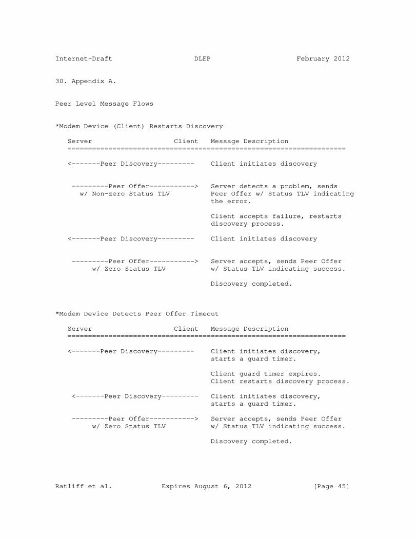
Internet-Draft DLEP February 2012
30. Appendix A.
Peer Level Message Flows
*Modem Device (Client) Restarts Discovery
Server Client Message Description ====================================================================
<-------Peer Discovery--------- Client initiates discovery
---------Peer Offer-----------> Server detects a problem, sends w/ Non-zero Status TLV Peer Offer w/ Status TLV indicating the error.
Client accepts failure, restarts discovery process.
<-------Peer Discovery--------- Client initiates discovery
---------Peer Offer-----------> Server accepts, sends Peer Offer w/ Zero Status TLV w/ Status TLV indicating success.
Discovery completed.
*Modem Device Detects Peer Offer Timeout
Server Client Message Description ====================================================================
<-------Peer Discovery--------- Client initiates discovery, starts a guard timer.
Client guard timer expires. Client restarts discovery process.
<-------Peer Discovery--------- Client initiates discovery, starts a guard timer.
---------Peer Offer-----------> Server accepts, sends Peer Offer w/ Zero Status TLV w/ Status TLV indicating success.
Discovery completed.
Ratliff et al. Expires August 6, 2012 [Page 45]

Internet-Draft DLEP February 2012
*Server Peer Offer Lost
Server Client Message Description ====================================================================
<-------Peer Discovery--------- Client initiates discovery, starts a guard timer.
---------Peer Offer-------|| Server offers availability
Client times out on Peer Offer, restarts discovery process.
<-------Peer Discovery--------- Client initiates discovery
---------Peer Offer-----------> Server detects subsequent discovery, internally terminates the previous, accepts the new association, sends Peer Offer w/ Status TLV indicating success.
Discovery completed.
*Discovery Success
Server Client Message Description ====================================================================
<-------Peer Discovery--------- Client initiates discovery
---------Peer Offer-----------> Server offers availability
-------Peer Heartbeat--------->
<-------Peer Heartbeat---------
-------Peer Heartbeat--------->
<==============================> Neighbor Sessions
<-------Peer Heartbeat---------
-------Peer Heartbeat--------->
--------Peer Term Req---------> Terminate Request
<--------Peer Term Res--------- Terminate Response
Ratliff et al. Expires August 6, 2012 [Page 46]

Internet-Draft DLEP February 2012
*Server Detects a Heartbeat timeout
Server Client Message Description ====================================================================
<-------Peer Heartbeat---------
-------Peer Heartbeat--------->
||---Peer Heartbeat---------
˜ ˜ ˜ ˜ ˜ ˜ ˜
-------Peer Heartbeat--------->
||---Peer Heartbeat--------- Server Heartbeat Timer expires, detects missing heartbeats. Server takes down all neighbor sessions and terminates the Peer association.
------Peer Terminate ---------> Peer Terminate Request
Client takes down all neighbor sessions, then acknowledges the Peer Terminate
<----Peer Terminate ACK--------- Peer Terminate ACK
*Client Detects a Heartbeat timeout
Server Client Message Description ====================================================================
<-------Peer Heartbeat---------
-------Peer Heartbeat------||
<-------Peer Heartbeat---------
˜ ˜ ˜ ˜ ˜ ˜ ˜
-------Peer Heartbeat------||
<-------Peer Heartbeat--------- Client Heartbeat Timer expires, detects missing heartbeats. Modem takes down all neighbor sessions and terminates the Peer association.
Ratliff et al. Expires August 6, 2012 [Page 47]
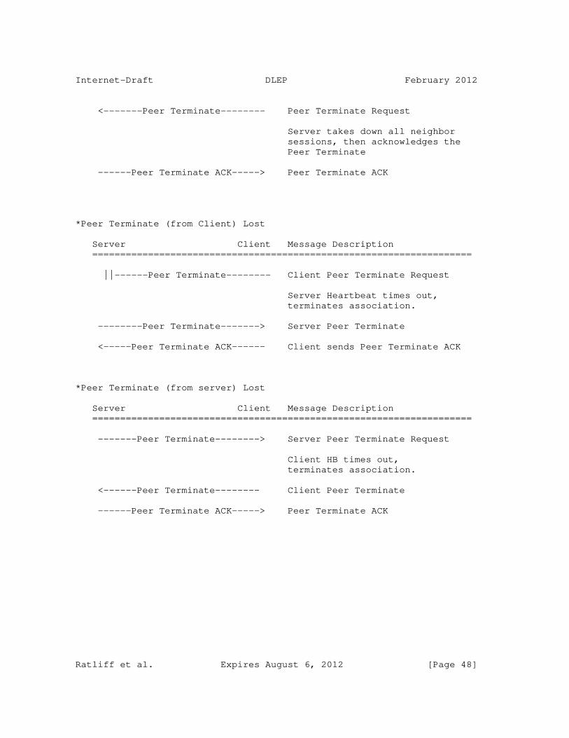
Internet-Draft DLEP February 2012
<-------Peer Terminate-------- Peer Terminate Request
Server takes down all neighbor sessions, then acknowledges the Peer Terminate
------Peer Terminate ACK-----> Peer Terminate ACK
*Peer Terminate (from Client) Lost
Server Client Message Description ====================================================================
||------Peer Terminate-------- Client Peer Terminate Request
Server Heartbeat times out, terminates association.
--------Peer Terminate-------> Server Peer Terminate
<-----Peer Terminate ACK------ Client sends Peer Terminate ACK
*Peer Terminate (from server) Lost
Server Client Message Description ====================================================================
-------Peer Terminate--------> Server Peer Terminate Request
Client HB times out, terminates association.
<------Peer Terminate-------- Client Peer Terminate
------Peer Terminate ACK-----> Peer Terminate ACK
Ratliff et al. Expires August 6, 2012 [Page 48]

Internet-Draft DLEP February 2012
Neighbor Level Message Flows
*Client Neighbor Up Lost
Server Client Message Description ====================================================================
||-----Neighbor Up ------------ Client sends Neighbor Up
Client timesout on ACK
<------Neighbor Up ------------ Client sends Neighbor Up
------Neighbor Up ACK---------> Server accepts the neighbor session
<------Neighbor Update--------- Client Neighbor Metrics . . . . . . . . <------Neighbor Update--------- Client Neighbor Metrics
*Server Detects Duplicate Neighbor Ups
Server Client Message Description ====================================================================
<------Neighbor Up ------------ Client sends Neighbor Up
------Neighbor Up ACK-------|| Server accepts the neighbor session
Client timesout on ACK
<------Neighbor Up ------------ Client resends Neighbor Up
Server detects duplicate Neighbor, takes down the previous, accepts the new Neighbor.
------Neighbor Up ACK---------> Server accepts the neighbor session
<------Neighbor Update--------- Client Neighbor Metrics . . . . . . . . <------Neighbor Update--------- Client Neighbor Metrics
Ratliff et al. Expires August 6, 2012 [Page 49]

Internet-Draft DLEP February 2012
*Neighbor Up, No Layer 3 Addresses
Server Client Message Description ====================================================================
<------Neighbor Up ------------ Client sends Neighbor Up
------Neighbor Up ACK---------> Server accepts the neighbor session
Server ARPs for IPv4 if defined. Server drives ND for IPv6 if defined.
<------Neighbor Update--------- Client Neighbor Metrics . . . . . . . . <------Neighbor Update--------- Client Neighbor Metrics
*Neighbor Up with IPv4, No IPv6
Server Client Message Description ====================================================================
<------Neighbor Up ------------ Client sends Neighbor Up with the IPv4 TLV
------Neighbor Up ACK---------> Server accepts the neighbor session
Server drives ND for IPv6 if defined.
<------Neighbor Update--------- Client Neighbor Metrics . . . . . . . . <------Neighbor Update--------- Client Neighbor Metrics
*Neighbor Up with IPv4 and IPv6
Server Client Message Description ====================================================================
<------Neighbor Up ------------ Client sends Neighbor Up with the IPv4 and IPv6 TLVs
------Neighbor Up ACK---------> Server accepts the neighbor session
<------Neighbor Update--------- Client Neighbor Metrics . . . . . . . . <------Neighbor Update--------- Client Neighbor Metrics
Ratliff et al. Expires August 6, 2012 [Page 50]

Internet-Draft DLEP February 2012
*Neighbor Session Success
Server Client Message Description ====================================================================
---------Peer Offer-----------> Server offers availability
-------Peer Heartbeat--------->
<------Neighbor Up ----------- Client
------Neighbor Up ACK--------> Server
<------Neighbor Update--------- Client . . . . . . . . <------Neighbor Update--------- Client
Client initiates the terminate
<------Neighbor Down ---------- Client
------Neighbor Down ACK-------> Server
or
Server initiates the terminate
------Neighbor Down ----------> Server
<------Neighbor Down ACK------- Client
Acknowledgements
The authors would like to acknowledge the influence and contributions of Chris Olsen, Teco Boot, Subir Das, Jaewon Kang, Vikram Kaul, Rick Taylor, and John Dowdell.
Normative References
[RFC5444] Clausen, T., Ed,. "Generalized Mobile Ad Hoc Network (MANET) Packet/Message Format", RFC 5444, Februar, 2009.
[RFC5578] Berry, B., Ed., "PPPoE with Credit Flow and Metrics", RFC 5578, February 2010.
[RFC2119] Bradner, S., "Key words for use in RFCs to Indicate Requirement Levels", RFC 2119, March 1997.
Ratliff et al. Expires August 6, 2012 [Page 51]

Internet-Draft DLEP February 2012
Informative References
[DTLS] Rescorla, E., Ed,. "Datagram Transport Layer Security", RFC 4347, April 2006.
Author’s Addresses
Stan Ratliff Cisco 170 West Tasman Drive San Jose, CA 95134 USA EMail: [email protected]
Bo Berry Cisco 170 West Tasman Drive San Jose, CA 95134 USA EMail: [email protected]
Greg Harrison Cisco 170 West Tasman Drive San Jose, CA 95134 USA EMail: [email protected]
Shawn Jury NetApp 7301 Kit Creek Road, Building 2 Research Triangle Park, NC 27709 USA Email: [email protected]
Darryl Satterwhite Cisco 170 West Tasman Drive San Jose, CA 95134 USA Email: [email protected]
Ratliff et al. Expires August 6, 2012 [Page 52]

Mobile Ad hoc Networks Working Group C. PerkinsInternet-DraftIntended status: Standards Track I. ChakeresExpires: September 13, 2012 CenGen March 12, 2012
Dynamic MANET On-demand (AODVv2) Routing draft-ietf-manet-dymo-22
Abstract
The Dynamic MANET On-demand (AODVv2) routing protocol is intended for use by mobile routers in wireless, multihop networks. AODVv2 determines unicast routes among AODVv2 routers within the network in an on-demand fashion, offering on-demand convergence in dynamic topologies.
Status of this Memo
This Internet-Draft is submitted in full conformance with the provisions of BCP 78 and BCP 79.
Internet-Drafts are working documents of the Internet Engineering Task Force (IETF). Note that other groups may also distribute working documents as Internet-Drafts. The list of current Internet- Drafts is at http://datatracker.ietf.org/drafts/current/.
Internet-Drafts are draft documents valid for a maximum of six months and may be updated, replaced, or obsoleted by other documents at any time. It is inappropriate to use Internet-Drafts as reference material or to cite them other than as "work in progress."
This Internet-Draft will expire on September 13, 2012.
Copyright Notice
Copyright (c) 2012 IETF Trust and the persons identified as the document authors. All rights reserved.
This document is subject to BCP 78 and the IETF Trust’s Legal Provisions Relating to IETF Documents (http://trustee.ietf.org/license-info) in effect on the date of publication of this document. Please review these documents carefully, as they describe your rights and restrictions with respect to this document. Code Components extracted from this document must include Simplified BSD License text as described in Section 4.e of the Trust Legal Provisions and are provided without warranty as
Perkins & Chakeres Expires September 13, 2012 [Page 1]
Internet-Draft AODVv2 March 2012
described in the Simplified BSD License.
Table of Contents
1. Overview . . . . . . . . . . . . . . . . . . . . . . . . . . . 4 2. Applicability Statement . . . . . . . . . . . . . . . . . . . 4 3. Terminology . . . . . . . . . . . . . . . . . . . . . . . . . 5 4. Data Structures . . . . . . . . . . . . . . . . . . . . . . . 7 4.1. Route Table Entry . . . . . . . . . . . . . . . . . . . . 7 4.2. AODVv2 Messages . . . . . . . . . . . . . . . . . . . . . 8 4.2.1. Generalized Packet and Message Structure . . . . . . . 9 4.2.2. Routing Message (RteMsg) - RREQ and RREP . . . . . . . 10 4.2.3. Route Error (RERR) . . . . . . . . . . . . . . . . . . 11 5. Detailed Operation . . . . . . . . . . . . . . . . . . . . . . 12 5.1. AODVv2 Sequence Numbers . . . . . . . . . . . . . . . . . 12 5.1.1. Maintaining A Node’s Own Sequence Number . . . . . . . 12 5.1.2. Numerical Operations on OwnSeqNum . . . . . . . . . . 13 5.1.3. OwnSeqNum Rollover . . . . . . . . . . . . . . . . . . 13 5.1.4. Actions After OwnSeqNum Loss . . . . . . . . . . . . . 13 5.2. AODVv2 Routing Table Operations . . . . . . . . . . . . . 13 5.2.1. Judging Routing Information’s Usefulness . . . . . . . 13 5.2.2. Creating or Updating a Route Table Entry with Received Preferable Routing Information . . . . . . . 15 5.2.3. Route Table Entry Timeouts . . . . . . . . . . . . . . 16 5.3. Routing Messages . . . . . . . . . . . . . . . . . . . . . 16 5.3.1. RREQ Creation . . . . . . . . . . . . . . . . . . . . 16 5.3.2. RREP Creation . . . . . . . . . . . . . . . . . . . . 17 5.3.3. RteMsg Handling . . . . . . . . . . . . . . . . . . . 18 5.4. Route Discovery . . . . . . . . . . . . . . . . . . . . . 21 5.5. Route Maintenance . . . . . . . . . . . . . . . . . . . . 22 5.5.1. Active Next-hop Router Adjacency Monitoring . . . . . 22 5.5.2. Updating Route Lifetimes During Packet Forwarding . . 23 5.5.3. RERR Generation . . . . . . . . . . . . . . . . . . . 23 5.5.4. RERR Handling . . . . . . . . . . . . . . . . . . . . 24 5.6. Unknown Message and TLV Types . . . . . . . . . . . . . . 25 5.7. Advertising Network Addresses . . . . . . . . . . . . . . 25 5.8. Simple Internet Attachment . . . . . . . . . . . . . . . . 25 5.9. Multiple Interfaces . . . . . . . . . . . . . . . . . . . 27 5.10. AODVv2 Control Packet/Message Generation Limits . . . . . 27 6. Administratively Configured Parameters and Timer Values . . . 27 7. IANA Considerations . . . . . . . . . . . . . . . . . . . . . 29 7.1. AODVv2 Message Types Specification . . . . . . . . . . . . 30 7.2. Message and Address Block TLV Type Specification . . . . . 30 7.3. Address Block TLV Specification . . . . . . . . . . . . . 31 8. Security Considerations . . . . . . . . . . . . . . . . . . . 31 9. Acknowledgments . . . . . . . . . . . . . . . . . . . . . . . 32 10. References . . . . . . . . . . . . . . . . . . . . . . . . . . 33
Perkins & Chakeres Expires September 13, 2012 [Page 2]

Internet-Draft AODVv2 March 2012
10.1. Normative References . . . . . . . . . . . . . . . . . . . 33 10.2. Informative References . . . . . . . . . . . . . . . . . . 33 Appendix A. Changes since the Previous Version . . . . . . . . . 34 Appendix B. Proposed additional changes for LOADng conformance . 34 Appendix C. Shifting Responsibility for an Address Between AODVv2 Routers . . . . . . . . . . . . . . . . . . . 35 Authors’ Addresses . . . . . . . . . . . . . . . . . . . . . . . . 35
Perkins & Chakeres Expires September 13, 2012 [Page 3]

Internet-Draft AODVv2 March 2012
1. Overview
The Dynamic MANET On-demand (AODVv2) routing protocol enables on- demand, multihop unicast routing among participating AODVv2 routers. The basic operations of the AODVv2 protocol are route discovery and route maintenance. Route discovery is performed when an AODVv2 router receives a packet from a node under its responsibility to a destination for which it does not have a route. Route maintenance is performed to help ensure that the route being used to forward packets from the source to the destination remains operational.
During route discovery, the originator’s AODVv2 router initiates dissemination of a Route Request (RREQ) throughout the network to find a route to a particular destination, via the AODVv2 router responsible for this destination. During this hop-by-hop dissemination process, each intermediate AODVv2 router records a route to the originator. When the target’s AODVv2 router receives the RREQ, it responds with a Route Reply (RREP) sent hop-by-hop toward the originating AODVv2 router. Each intermediate AODVv2 router that receives the RREP creates a route to the target, and then the RREP is unicast hop-by-hop toward the originator. When the originator’s AODVv2 router receives the RREP, routes have then been established between the originating AODVv2 router and the target AODVv2 router in both directions.
Route maintenance consists of two operations. In order to preserve routes in use, AODVv2 routers extend route lifetimes upon successfully forwarding a packet. In order to react to changes in the network topology, AODVv2 routers monitor traffic being forwarded. When a data packet is received for forwarding and a route for the destination is not known or the route is broken, then the AODVv2 router of the source of the packet is notified. A Route Error (RERR) is sent toward the packet source to indicate the route to particular destination addresses is invalid or missing. When the source’s AODVv2 router receives the RERR, it deletes the route. If this source’s AODVv2 router later receives a packet for forwarding to the same destination, it will need to perform route discovery again for that destination.
AODVv2 uses sequence numbers to ensure loop freedom [Perkins99]. Sequence numbers enable AODVv2 routers to determine the temporal order of AODVv2 route discovery messages, thereby avoiding use of stale routing information.
2. Applicability Statement
The AODVv2 routing protocol is designed for stub or disconnected
Perkins & Chakeres Expires September 13, 2012 [Page 4]

Internet-Draft AODVv2 March 2012
mobile ad hoc networks (MANETs). AODVv2 handles a wide variety of mobility patterns by dynamically determining routes on-demand. AODVv2 also handles a wide variety of traffic patterns. In networks with a large number of routers, AODVv2 is best suited for sparse traffic scenarios where routers forward packets to only a small portion of the other AODVv2 routers, due to the on-demand nature of route discovery and route maintenance.
AODVv2 is applicable to memory constrained devices, since little routing state is maintained in each AODVv2 router. Only routing information related to active sources and destinations is maintained, in contrast to most proactive routing protocols that require routing information to all routers within the routing region be maintained.
AODVv2 supports routers with multiple interfaces participating in the MANET. AODVv2 routers can also perform routing on behalf of other nodes, attached via participating or non-participating interfaces.
AODVv2 routers perform route discovery to find a route to a particular destination. Therefore, AODVv2 routers MUST be configured to initiate and respond to route discovery on behalf of certain nodes, identified by address. When AODVv2 is the only protocol interacting with the forwarding table, AODVv2 MAY be configured to perform route discovery for all unknown unicast destinations.
At any time within an AODVv2 routing region, only one AODVv2 router SHOULD be responsible for, i.e. "own", any particular address. Coordination among multiple AODVv2 routers to distribute routing information correctly for a shared address (i.e. an address that is advertised and can be reached via multiple AODVv2 routers) is not described in this document. The router behavior for shifting responsibility for an address from one AODVv2 router to another is mentioned in Appendix C.
AODVv2 only utilizes bidirectional links. In the case of possible unidirectional links, either blacklists (see Section 7.2) or other means (e.g. adjacency establishment with only neighboring routers that have bidirectional communication as indicated by NHDP [I-D.ietf-manet-nhdp]) of ensuring and monitoring bi-directionality is recommended. Otherwise, persistent packet loss may occur.
The routing algorithm in AODVv2 may be operated at layers other than the network layer, using layer-appropriate addresses.
3. Terminology
The key words "MUST", "MUST NOT", "REQUIRED", "SHALL", "SHALL NOT",
Perkins & Chakeres Expires September 13, 2012 [Page 5]

Internet-Draft AODVv2 March 2012
"SHOULD", "SHOULD NOT", "RECOMMENDED", "MAY", and "OPTIONAL" in this document are to be interpreted as described in [RFC2119].
Additionally, this document uses some terminology from [RFC5444].
This document defines the following terminology:
Adjacency A relationship between selected bi-directional neighboring routers for the purpose of exchanging routing information. Not every pair of neighboring routers will necessarily form an adjacency. Neighboring routers may form an adjacency based several different pieces of information or protocols; for example, exchange of AODVv2 routing messages, other protocols (e.g. NDP [RFC4861] or NHDP [I-D.ietf-manet-nhdp]), or manual configuration. Similarly, loss of a routing adjacency may also be based upon several pieces of information, and monitoring of adjacencies where packets are being forwarded is required (see Section 5.5.1).
Distance (Dist) A metric of the distance a message or piece of information has traversed. The minimum value of distance is the number of IP hops traversed. The maximum value is 65,535.
AODVv2 Sequence Number (SeqNum) An AODVv2 Sequence Number is maintained by each AODVv2 router process. This sequence number is used by other AODVv2 routers to identify the temporal order of routing information generated and ensure loop-free routes.
Multihop-capable Unicast IP Address A multihop-capable unicast IP address is a unicast IP address that when put into the IP.SourceAddress or IP.DestinationAddress field is scoped sufficiently to be forwarded by a router. Globally- scoped unicast IP addresses and Unique Local Addresses (ULAs) are examples of multihop-capable unicast IP addresses.
Originating Node (OrigNode) The originating node is the source, its AODVv2 router creates a AODVv2 control message on its behalf in an effort to disseminate some routing information. The originating node is also referred to as a particular message’s originator.
Route Error (RERR) A RERR message is used to indicate that an AODVv2 router does not have a forwarding route to one or more particular addresses.
Perkins & Chakeres Expires September 13, 2012 [Page 6]

Internet-Draft AODVv2 March 2012
Route Reply (RREP) A RREP message is used to disseminate routing information about the RREP TargetNode to the RREP OrigNode and the AODVv2 routers between them.
Route Request (RREQ) A RREQ message is used to discover a valid route to a particular destination address, called the RREQ TargetNode. When an AODVv2 router processes a RREQ, it learns routing information on how to reach the RREQ OrigNode.
Target Node (TargetNode) The TargetNode is the ultimate destination of a message.
This Node (ThisNode) ThisNode corresponds to the AODVv2 router process currently performing a calculation or attending to a message.
Type-Length-Value structure (TLV) A generic way to represent information, please see [RFC5444] for additional information.
Unreachable Node (UnreachableNode) An UnreachableNode is a node for which a forwarding route is unknown.
4. Data Structures
4.1. Route Table Entry
The route table entry is a conceptual data structure. Implementations may use any internal representation that conforms to the semantics of a route as specified in this document.
Conceptually, a route table entry has the following fields:
Route.Address The (host or network) destination address of the node(s) associated with the routing table entry.
Route.Prefix Indicates that the associated address is a network address, rather than a host address. The value is the length of the netmask/ prefix.
Perkins & Chakeres Expires September 13, 2012 [Page 7]

Internet-Draft AODVv2 March 2012
Route.SeqNum The AODVv2 SeqNum associated with this routing information.
Route.NextHopAddress The IP address of the adjacent AODVv2 router on the path toward the Route.Address.
Route.NextHopInterface The interface used to send packets toward the Route.Address.
Route.Forwarding A flag indicating whether this Route can be used for forwarding data packets. This flag MAY be provided for management and monitoring.
Route.Broken A flag indicating whether this Route is broken. This flag is set to true if the next-hop becomes unreachable or in response to attending to a RERR (see Section 5.5.4).
The following field is optional:
Route.Dist A dimensionless metric indicating the distance traversed before reaching the Route.Address node.
Not including optional information may cause performance degradation, but it will not cause the protocol to operate incorrectly.
In addition to a route table data structure, each route table entry may have several timers associated with the information. These timers/timeouts are discussed in Section 5.2.3.
4.2. AODVv2 Messages
When describing AODVv2 protocol messages, it is necessary to refer to fields in several distinct parts of the overall packet. These locations include the IP header, the UDP header, and fields from [RFC5444]. This document uses the following notation conventions. Information found in the table.
Perkins & Chakeres Expires September 13, 2012 [Page 8]
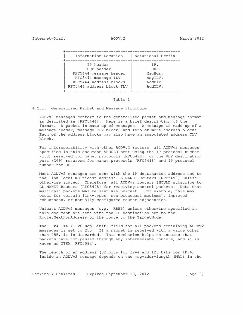
Internet-Draft AODVv2 March 2012
+---------------------------+-------------------+ | Information Location | Notational Prefix | +---------------------------+-------------------+ | IP header | IP. | | UDP header | UDP. | | RFC5444 message header | MsgHdr. | | RFC5444 message TLV | MsgTLV. | | RFC5444 address blocks | AddBlk. | | RFC5444 address block TLV | AddTLV. | +---------------------------+-------------------+
Table 1
4.2.1. Generalized Packet and Message Structure
AODVv2 messages conform to the generalized packet and message format as described in [RFC5444]. Here is a brief description of the format. A packet is made up of messages. A message is made up of a message header, message TLV block, and zero or more address blocks. Each of the address blocks may also have an associated address TLV block.
For interoperability with other AODVv2 routers, all AODVv2 messages specified in this document SHOULD sent using the IP protocol number (138) reserved for manet protocols [RFC5498]; or the UDP destination port (269) reserved for manet protocols [RFC5498] and IP protocol number for UDP.
Most AODVv2 messages are sent with the IP destination address set to the link-local multicast address LL-MANET-Routers [RFC5498] unless otherwise stated. Therefore, all AODVv2 routers SHOULD subscribe to LL-MANET-Routers [RFC5498] for receiving control packets. Note that multicast packets MAY be sent via unicast. For example, this may occur for certain link-types (non broadcast mediums), improved robustness, or manually configured router adjacencies.
Unicast AODVv2 messages (e.g. RREP) unless otherwise specified in this document are sent with the IP destination set to the Route.NextHopAddress of the route to the TargetNode.
The IPv4 TTL (IPv6 Hop Limit) field for all packets containing AODVv2 messages is set to 255. If a packet is received with a value other than 255, it is discarded. This mechanism helps to ensures that packets have not passed through any intermediate routers, and it is known as GTSM [RFC5082].
The length of an address (32 bits for IPv4 and 128 bits for IPv6) inside an AODVv2 message depends on the msg-addr-length (MAL) in the
Perkins & Chakeres Expires September 13, 2012 [Page 9]

Internet-Draft AODVv2 March 2012
msg-header, as specified in [RFC5444].
AODVv2 control packets SHOULD be given priority queuing and channel access.
4.2.2. Routing Message (RteMsg) - RREQ and RREP
Routing Messages (RteMsgs) are used to disseminate routing information. There are two AODVv2 message types that are considered to be routing messages (RteMsgs): RREQ and RREP. They contain very similar information and function, but have slightly different handling rules. The main difference between the two messages is that RREQ messages generally solicit a RREP, whereas a RREP is the response to RREQ.
RteMsg creation and handling are described in Section 5.3.
A RteMsg requires the following information:
IP.SourceAddress The IP address of the node currently sending this packet. This field is generally filled automatically by the operating system and should not require special handling.
IP.DestinationAddress The IP address of the packet destination. For multicast RREQ the IP.DestinationAddress is set to LL-MANET-Routers [RFC5498]. For unicast RREP the IP.DestinationAddress is set to the NextHopAddress toward the RREP TargetNode.
IP.ProtocolNumber and UDP.DestinationPort The IP Protocol Number 138 (manet) has been reserved for MANET protocols [RFC5498]. In addition to using this IP protocol number, AODVv2 may use the UDP port 269 (manet) [RFC5498] in conjunction with the IP Protocol Number 17 (UDP).
MsgHdr.HopLimit The remaining number of hops this message is allowed to traverse.
AddBlk.TargetNode.Address The IP address of the message TargetNode. In a RREQ the TargetNode is the destination address for which route discovery is being performed. In a RREP the TargetNode is the RREQ OrigNode address. The TargetNode address is the first address in a routing message.
Perkins & Chakeres Expires September 13, 2012 [Page 10]

Internet-Draft AODVv2 March 2012
AddBlk.OrigNode.Address The IP address of the originator and its associated prefix length. In a RREQ the OrigNode is the source’s address and prefix. In a RREP the OrigNode is the RREQ TargetNode’s address and prefix for which a RREP is being generated. This address is the second address in the message for RREQ.
OrigNode.AddTLV.SeqNum The AODVv2 sequence number of the originator’s AODVv2 router.
A RteMsg may optionally include the following information:
TargetNode.AddTLV.SeqNum The last known AODVv2 sequence number of the TargetNode.
TargetNode.AddTLV.Dist The last known Distance to the TargetNode.
AddBlk.AdditionalNode.Address The IP address of an additional node that can be reached via the AODVv2 router adding this information. Each AdditionalNode.Address MUST include its prefix. Each AdditionalNode.Address MUST also have an associated Node.SeqNum in the address TLV block.
AdditionalNode.AddTLV.SeqNum The AODVv2 sequence number associated with this routing information.
OrigNode.AddTLV.Dist A metric of the distance to reach the associated OrigNode.Address. This field is incremented by at least one at each intermediate AODVv2 router.
AdditionalNode.AddTLV.Dist A metric of the distance to reach the associated AdditionalNode.Address. This field is incremented by at least one at each intermediate AODVv2 router.
4.2.3. Route Error (RERR)
A RERR message is used to disseminate the information that a route is not available for one or more particular addresses.
RERR creation and handling are described in Section 5.5.
A RERR requires the following information:
Perkins & Chakeres Expires September 13, 2012 [Page 11]

Internet-Draft AODVv2 March 2012
IP.SourceAddress The IP address of the AODVv2 router that sent this packet. This field is generally filled automatically by the operating system and should not require special handling.
IP.DestinationAddress For multicast RERR messages, The IP address is set to LL-MANET- Routers [RFC5498]. For unicast RERR messages, the IP address is set to the NextHopAddress.
IP.ProtocolNumber and UDP.DestinationPort The IP Protocol Number 138 (manet) has been reserved for MANET protocols [RFC5498]. In addition to using this IP protocol number, AODVv2 may use the UDP port 269 (manet) [RFC5498] in conjunction with the IP Protocol Number 17 (UDP).
MsgHdr.HopLimit The remaining number of hops this message is allowed to traverse.
AddBlk.UnreachableNode.Address The address of an UnreachableNode and its associated prefix length. Multiple unreachable addresses may be included in a RERR.
A Route Error may optionally include the following information:
UnreachableNode.AddTLV.SeqNum The last known AODVv2 sequence number of the unreachable node. If a SeqNum for an address is zero (0) or not included, it is assumed to be unknown. This case occurs when a node receives a message to forward to a destination for which it does not have any information in its routing table.
5. Detailed Operation
5.1. AODVv2 Sequence Numbers
AODVv2 sequence numbers allow AODVv2 routers to judge the freshness of routing information and ensure loop freedom.
5.1.1. Maintaining A Node’s Own Sequence Number
AODVv2 requires that each AODVv2 router in the network maintain its own AODVv2 sequence number (OwnSeqNum) on behalf of the addresses for which it is responsible. OwnSeqNum a 16-bit unsigned integer. The circumstances for ThisNode to increment its OwnSeqNum are described in Section 5.3.
Perkins & Chakeres Expires September 13, 2012 [Page 12]

Internet-Draft AODVv2 March 2012
5.1.2. Numerical Operations on OwnSeqNum
When ThisNode increments its OwnSeqNum it MUST do so by treating the sequence number value as an unsigned number.
5.1.3. OwnSeqNum Rollover
Incrementing an OwnSeqNum whose value is the largest largest possible number representable as a 16-bit unsigned integer (i.e., 65,535), SHOULD be set to one (1). In other words, the sequence number after 65,535 is 1.
5.1.4. Actions After OwnSeqNum Loss
An AODVv2 router SHOULD maintain its sequence number in persistent storage.
If an AODVv2 router’s OwnSeqNum is lost, it MUST take certain actions to avoid creating routing loops. To prevent this possibility after OwnSeqNum loss an AODVv2 router MUST wait for at least ROUTE_DELETE_TIMEOUT before fully participating in the AODVv2 routing protocol. If an AODVv2 control message is received during this waiting period, the AODVv2 router SHOULD handle it normally but MUST NOT transmit or retransmit any AODVv2 messages. If a data packet is received for forwarding to another destination during this waiting period, the AODVv2 router MUST generate a RERR message indicating that this route is not available and reset its waiting timeout. At the end of the waiting period the AODVv2 router sets its OwnSeqNum to one (1) and begins participating.
The longest a node need wait is ROUTE_SEQNUM_AGE_MAX_TIMEOUT. At the end of the maximum waiting period a node SHOULD set its OwnSeqNum to one (1) and begins participating.
5.2. AODVv2 Routing Table Operations
5.2.1. Judging Routing Information’s Usefulness
Given a route table entry (Route.SeqNum, Route.Dist, and Route.Broken) and new incoming routing information for a particular node in a RteMsg (Node.SeqNum, Node.Dist, and RteMsg message type - RREQ/RREP), the quality of the new routing information is evaluated to determine its usefulness. Incoming routing information is classified as follows:
Perkins & Chakeres Expires September 13, 2012 [Page 13]

Internet-Draft AODVv2 March 2012
1. Stale If Node.SeqNum - Route.SeqNum < 0 (using signed 16-bit arithmetic) the incoming information is stale. Using stale routing information is not allowed, since doing so might result in routing loops.
(Node.SeqNum - Route.SeqNum < 0) using signed 16-bit arithmetic
2. Loop-possible If Node.SeqNum == Route.SeqNum the incoming information may cause loops if used; in this case additional information MUST be examined. If Route.Dist or Node.Dist is unknown or zero (0), then the routing information is loop-possible. If Node.Dist > Route.Dist + 1, then the routing information is loop-possible. Using loop-possible routing information is not allowed, otherwise routing loops may be formed.
(Node.SeqNum == Route.SeqNum) AND ((Node.Dist is unknown) OR (Route.Dist is unknown) OR (Node.Dist > Route.Dist + 1))
3. Disfavored or equivalent In case of known equal SeqNum, the information is disfavored in multiple cases: (case i) if Node.Dist == Route.Dist + 1 (it is a greater distance route) AND Route.Broken == false; (case ii) if Node.Dist == Route.Dist (equal distance route) AND Route.Broken == false AND this RteMsg is a RREQ. This condition reduces the number of RREQ flooded by stopping forwarding of RREQ with equivalent distance.
((Node.SeqNum == Route.SeqNum) AND (((Node.Dist == Route.Dist + 1) AND (Route.Broken == false)) OR ((Node.Dist == Route.Dist) AND (RteMsg is RREQ) AND (Route.Broken == false))))
4. Preferable Incoming routing information that does not match any of the above criteria is loop-free and better than the information existing in the routing table. Information is always preferable if Node.SeqNum - Route.SeqNum > 0 (using signed 16-bit arithmetic). In the case of equal sequence numbers, the information is preferable in multiple cases: (case i) if Node.Dist < Route.Dist; (case ii) if Node.Dist == Route.Dist + 1 AND Route.Broken == true (a broken route is being repaired); (case iii) if Node.Dist == Route.Dist AND it is a RREP (RREP with equal distance are forwarded) OR Route.Broken == true (a broken route is being
Perkins & Chakeres Expires September 13, 2012 [Page 14]

Internet-Draft AODVv2 March 2012
repaired). For completeness, we provide the following (optimized) pseudo-code.
(Node.SeqNum - Route.SeqNum > 0) OR using signed 16-bit arithmetic ((Node.SeqNum == Route.SeqNum) AND ((Node.Dist < Route.Dist) OR ((Node.Dist == Route.Dist + 1) AND (Route.Broken == true)) OR ((Node.Dist == Route.Dist) AND ((RteMsg is RREP) OR (Route.Broken == true)))))
5.2.2. Creating or Updating a Route Table Entry with Received Preferable Routing Information
The route table entry is populated with the following information:
1. the Route.Address is set to Node.Address,
2. the Route.Prefix is set to the Node.Prefix.
3. the Route.SeqNum is set to the Node.SeqNum,
4. the Route.NextHopAddress is set to the node that transmitted this AODVv2 RteMsg packet (i.e., the IP.SourceAddress),
5. the Route.NextHopInterface is set to the interface that this AODVv2 packet was received on,
6. the Route.Broken flag is set to false,
7. if known, the Route.Dist is set to the Node.Dist,
Fields without known values are not populated with any value.
The timer for the minimum delete timeout (ROUTE_AGE_MIN) is set to ROUTE_AGE_MIN_TIMEOUT. The timer for the maximum delete timeout (ROUTE_SEQNUM_AGE_MAX) is set to Node.AddTLV.VALIDITY_TIME [RFC5497] if included; otherwise, ROUTE_SEQNUM_AGE_MAX is set to ROUTE_SEQNUM_AGE_MAX_TIMEOUT. The usage of these timers and others are described in Section 5.2.3.
At this point, a forwarding route has been created and the Route.Forwarding flag set. Afterward, the route can be used to send any queued data packets and forward any incoming data packets for Route.Address. This route also fulfills any outstanding route discovery attempts for Node.Address.
Perkins & Chakeres Expires September 13, 2012 [Page 15]

Internet-Draft AODVv2 March 2012
5.2.3. Route Table Entry Timeouts
5.2.3.1. Minimum Delete Timeout (ROUTE_AGE_MIN)
When an AODVv2 router transmits a RteMsg, other AODVv2 routers expect the transmitting AODVv2 router to have a forwarding route to the RteMsg originator. After updating a route table entry, it SHOULD be maintained for at least ROUTE_AGE_MIN. Failure to maintain the information might result in lost messages/packets, or in the worst case scenario several duplicate messages.
After the ROUTE_AGE_MIN timeout a route can safely be deleted.
5.2.3.2. Maximum Sequence Number Delete Timeout (ROUTE_SEQNUM_AGE_MAX)
Sequence number information is time sensitive, and MUST be deleted after a time in order to ensure loop-free routing.
After the ROUTE_SEQNUM_AGE_MAX timeout a route’s sequence number information MUST be discarded.
5.2.3.3. Recently Used Timeout (ROUTE_USED)
When a route is used to forward data packets, this timer is set to expire after ROUTE_USED_TIMEOUT. This operation is also discussed in Section 5.5.2.
If a route has not been used recently, then a timer for ROUTE_DELETE is set to ROUTE_DELETE_TIMEOUT.
5.2.3.4. Delete Information Timeout (ROUTE_DELETE)
As time progresses the likelihood that old routing information is useful decreases, especially if the network nodes are mobile. Therefore, old information SHOULD be deleted.
After the ROUTE_DELETE timeout if a forwarding route exists it SHOULD be removed, and the routing table entry SHOULD also be deleted.
5.3. Routing Messages
5.3.1. RREQ Creation
Before an AODVv2 router creates a RREQ it SHOULD increment its OwnSeqNum by one (1) according to the rules specified in Section 5.1. Incrementing OwnSeqNum will ensure that all nodes with existing routing information will consider this new information preferable to existing routing table information. If the sequence number is not
Perkins & Chakeres Expires September 13, 2012 [Page 16]

Internet-Draft AODVv2 March 2012
incremented, certain AODVv2 routers might not consider this information preferable, if they have existing better routing information.
First, ThisNode adds the AddBlk.TargetNode.Address to the RREQ; the unicast IP Destination Address for which a forwarding route does not exist.
If a previous value of the TargetNode.SeqNum is known (from a routing table entry using longest-prefix matching), it SHOULD be placed in TargetNode.AddTLV.SeqNum in all but the last RREQ attempt. If a TargetNode.SeqNum is not included, it is assumed to be unknown by handling nodes. This operation ensures that no intermediate AODVv2 routers reply, and ensures that the TargetNode’s AODVv2 router increments its sequence number.
Next, the node adds AddBlk.OrigNode.Address, its prefix, and the OrigNode.AddTLV.SeqNum (OwnSeqNum) to the RteMsg.
The OrigNode.Address is the address of the source for which this AODVv2 router is initiating this route discovery. The OrigNode.Address MUST be a unicast address. This information will be used by nodes to create a route toward the OrigNode, enabling delivery of a RREP, and eventually used for proper forwarding of data packets.
If OrigNode.Dist is included it is set to a number greater than zero (0).
The MsgHdr.HopLimit SHOULD be set to MSG_HOPLIMIT.
For RREQ, the MsgHdr.HopLimit MAY be set in accordance with an expanding ring search as described in [RFC3561] to limit the RREQ propagation to a subset of the local network and possibly reduce route discovery overhead.
The IP.DestinationAddress for multicast RREQ is set to LL-MANET- Routers. For links that do not support multicast or situations in which unicast messaging is preferred, the IP.DestinationAddress for unicast RREQ is set to the NextHopAddress.
5.3.2. RREP Creation
First, the AddBlk.TargetNode.Address is added to the RREP. The TargetNode is the ultimate destination of this RREP; the RREQ OrigNode.Address.
Next, AddBlk.OrigNode.Address and prefix are added to the RREP. The
Perkins & Chakeres Expires September 13, 2012 [Page 17]

Internet-Draft AODVv2 March 2012
AddBlk.OrigNode.Address is the RREQ TargetNode.Address. The AddBlk.OrigNode.Address MUST be a unicast IP address. ThisNode SHOULD advertise the largest known prefix containing AddBlk.OrigNode.Address.
When the RteMsg TargetNode’s AODVv2 router creates a RREP, if the TargetNode.SeqNum was not included in the RREQ, ThisNode MUST increment its OwnSeqNum by one (1) according to the rules specified in Section 5.1.
If TargetNode.SeqNum was included in the RteMsg and TargetNode.SeqNum - OwnSeqNum < 0 (using signed 16-bit arithmetic), OwnSeqNum SHOULD be incremented by one (1) according to the rules specified in Section 5.1.
If TargetNode.SeqNum is included in the RteMsg and TargetNode.SeqNum == OwnSeqNum (using signed 16-bit arithmetic) and OrigNode.Dist will not be included in the RREP being generated, OwnSeqNum SHOULD be incremented by one (1) according to the rules specified in Section 5.1.
If OwnSeqNum is not incremented the routing information might be considered stale. In this case, the RREP might not reach the RREP Target.
After any of the sequence number operations above, the RREP OrigNode.AddTLV.SeqNum (OwnSeqNum) MUST also be added to the RREP.
Other AddTLVs in the RREP for the OrigNode and TargetNode SHOULD be included and set accordingly. If OrigNode.Dist is included it is set to a number greater than zero (0) and less than or equal to 65,535. The Distance value will influence judgment of the routing information (Section 5.2.1) against known information at other AODVv2 routers that handle this RteMsg.
The MsgHdr.HopLimit is set to MSG_HOPLIMIT.
The IP.DestinationAddress for RREP is set to the IP address of the Route.NextHopAddress for the route to the RREP TargetNode.
5.3.3. RteMsg Handling
First, ThisNode examines the RteMsg to ensure that it contains the required information: MsgHdr.HopLimit, AddBlk.TargetNode.Address, AddBlk.OrigNode.Address, and OrigNode.AddTLV.SeqNum. If the required information do not exist, the message is discarded and further processing stopped.
Perkins & Chakeres Expires September 13, 2012 [Page 18]

Internet-Draft AODVv2 March 2012
Next, ThisNode MAY selectively attend to messages based upon information in the message. ThisNode SHOULD only handle messages from adjacent AODVv2 routers. If ThisNode chooses not to handle this message, the message is discarded and further processing stopped.
ThisNode checks if the AddBlk.OrigNode.Address is a valid multihop- capable (e.g. site or global scope) unicast address. If the address is not a valid unicast address, the message is discarded and further processing stopped.
ThisNode also checks whether AddBlk.OrigNode.Address is an address handled by this AODVv2 router. If this node is the originating AODVv2 router, the RteMsg is dropped.
ThisNode checks if the AddBlk.TargetNode.Address is a valid multihop- capable unicast address. If the address is not a valid unicast address, the message is discarded and further processing stopped.
Next, ThisNode checks whether its routing table has an entry to the AddBlk.OrigNode.Address using longest-prefix matching [RFC1812]. If a route with a valid Route.SeqNum does not exist, then the new routing information is considered preferable and a new route table entry is created and updated as described in Section 5.2.2. If a route table entry does exists and it has a known Route.SeqNum, the incoming routing information is compared with the route table entry following the procedure described in Section 5.2.1. If the incoming routing information is considered preferable, the route table entry is updated as described in Section 5.2.2.
For each address (except the TargetNode) in the RteMsg that includes AddTLV.Dist information, the AddTLV.Dist information MAY be incremented. If the resulting Distance value for the OrigNode is greater than 65,535, the message is discarded. If the resulting Distance value for another node is greater than 65,535, the associated address and its information are removed from the RteMsg. The updated Distance value will influence judgment of the routing information (Section 5.2.1).
After handling the OrigNode’s routing information, then each address that is not the TargetNode MAY be considered for creating and updating routes. Creating and updating routes to other nodes can eliminate RREQ for those IP destinations, in the event that data needs to be forwarded to the IP destination(s) now or in the near future.
For each of the additional addresses considered, ThisNode first checks the that the address is a multihop-capable unicast address. If the address is not a unicast address, the address and all related
Perkins & Chakeres Expires September 13, 2012 [Page 19]

Internet-Draft AODVv2 March 2012
information MUST be removed.
If the routing table does not have a matching route with a known Route.SeqNum for this additional address using longest-prefix matching, then a route is created and updated as described in Section 5.2.2. If a route table entry exists with a known Route.SeqNum, the incoming routing information is compared with the route table entry following the procedure described in Section 5.2.1. If the incoming routing information is considered preferable, the route table entry is updated as described in Section 5.2.2.
If the routing information for an AdditionalNode.Address is not considered preferable, then it is removed from the RteMsg. Removing this information ensures that the information is not propagated.
At this point, if the routing information for the OrigNode was not preferable then this RteMsg SHOULD be discarded and no further processing of this message SHOULD be performed.
If the ThisNode is the AODVv2 router responsible for the TargetNode and this RteMsg is a RREQ, then ThisNode responds with a RREP to the RREQ OrigNode (the new RREP’s TargetNode). The procedure for issuing a new RREP is described in Section 5.3.2. At this point, ThisNode need not perform any more operations for the RteMsg being processed.
As an alternative to issuing a RREP, ThisNode MAY choose to distribute routing information about ThisNode (the RREQ TargetNode) more widely. That is, ThisNode MAY optionally perform a route discovery; by issuing a RREQ with ThisNode listed as the TargetNode, using the procedure in Section 5.3.1. At this point, ThisNode need not perform any more operations for the RteMsg being processed.
If the resulting Distance value for the OrigNode is greater than 65,535, the message is discarded. If the resulting Distance value for another node is greater than 65,535, the associated address and its information are removed from the RteMsg.
Next, the MsgHdr.HopLimit is decremented by one (1). If this RteMsg’s MsgHdr.HopLimit is greater than or equal to one (1), ThisNode is not the TargetNode, AND this RteMsg is a RREQ, then the current RteMsg (altered by the procedure defined above) SHOULD be sent to the IP.DestinationAddress LL-MANET-Routers [RFC5498]. If the RREQ is unicast, the IP.DestinationAddress is set to the NextHopAddress.
If this RteMsg’s MsgHdr.HopLimit is greater than or equal to one (1), ThisNode is not the TargetNode, AND this RteMsg is a RREP, then the current RteMsg is sent to the Route.NextHopAddress for the RREP’s
Perkins & Chakeres Expires September 13, 2012 [Page 20]

Internet-Draft AODVv2 March 2012
TargetNode.Address. If no forwarding route exists to TargetNode.Address, then a RERR SHOULD be issued to the OrigNode of the RREP.
By sending the updated RteMsg, ThisNode advertises that it will route for addresses contained in the outgoing RteMsg based on the information enclosed. ThisNode MAY choose not to send the RteMsg, though not resending this RteMsg could decrease connectivity in the network or result in a non-shortest distance path.
Some examples of why ThisNode might choose to not re-issue a RteMsg are: if ThisNode does not want to advertise routing for the contained addresses because it is already heavily loaded; if ThisNode has already issued nearly identical routing information (e.g. ThisNode had recently issued a RteMsg with nearly the same distance); or if ThisNode is low on energy and does not want to expend energy for control message sending or packet forwarding. The exact circumstances producing such behavior are not specified in this document.
5.4. Route Discovery
When a source’s AODVv2 router needs to forward a data packet on behalf of an attached node and it does not have a forwarding route to the data packet’s unicast IP destination address, ThisNode sends a RREQ (described in Section 5.3.1) to discover a route to the particular destination (TargetNode).
After issuing a RREQ, the OrigNode AODVv2 router waits for a route to be created to the TargetNode. If a route is not created within RREQ_WAIT_TIME, ThisNode may again try to discover a route by issuing another RREQ using the procedure defined in Section 5.3.1 again. Route discovery SHOULD be considered failed after DISCOVERY_ATTEMPTS_MAX and the final RREQ’s corresponding RREQ_WAIT_TIME.
To reduce congestion in a network, repeated attempts at route discovery for a particular TargetNode SHOULD utilize an exponential backoff.
For example, the first time an AODVv2 router issues a RREQ, it waits RREQ_WAIT_TIME for a route to the TargetNode. If a route is not found within that time, the AODVv2 router MAY send another RREQ. If a route is not found within two (2) times the current waiting time, another RREQ MAY be sent. No more than DISCOVERY_ATTEMPTS_MAX route discovery attempts SHOULD be made before considering route discovery for this destination to have failed. For each additional attempt, the waiting time for the previous RREQ is multiplied by two (2) so
Perkins & Chakeres Expires September 13, 2012 [Page 21]

Internet-Draft AODVv2 March 2012
that the waiting time conforms to a binary exponential backoff.
Data packets awaiting a route SHOULD be buffered by the source’s AODVv2 router. This buffer SHOULD have a fixed limited size (BUFFER_SIZE_PACKETS or BUFFER_SIZE_BYTES) and older data packets SHOULD be discarded first.
Buffering of data packets can have both positive and negative effects, and therefore buffer settings (BUFFER_DURING_DISCOVERY) SHOULD be administratively configurable or intelligently controlled.
If a route discovery attempt has failed (i.e. an attempt or multiple attempts have been made without receiving a RREP) to find a route to the TargetNode, any data packets buffered for the corresponding TargetNode are dropped and a Destination Unreachable ICMP message SHOULD be delivered to the source.
5.5. Route Maintenance
A RERR SHOULD be issued if a data packet is to be forwarded and it cannot be delivered to the next-hop because no forwarding route for the IP.DestinationAddress exists; RERR generation is described in Section 5.5.3.
Upon this condition, an ICMP Destination Unreachable message SHOULD NOT be generated unless this router is responsible for the IP.DestinationAddress and that IP.DestinationAddress is known to be unreachable.
In addition to inability to forward a data packet, a RERR SHOULD be issued immediately after detecting a broken link (see Section 5.5.1) of a forwarding route to quickly notify AODVv2 routers that certain routes are no longer available. If a newly unavailable route has not been used recently (indicated by ROUTE_USED), the RERR SHOULD NOT be generated.
5.5.1. Active Next-hop Router Adjacency Monitoring
Nodes MUST monitor connectivity to adjacent next-hop AODVv2 routers on forwarding routes. This monitoring can be accomplished by one or several mechanisms, including:
o Neighborhood discovery [I-D.ietf-manet-nhdp]
o Route timeout
o Lower layer feedback that a particular adjacent router is no longer reachable
Perkins & Chakeres Expires September 13, 2012 [Page 22]

Internet-Draft AODVv2 March 2012
o Other monitoring mechanisms or heuristics
Upon determining that a next-hop AODVv2 router is unreachable, ThisNode MUST remove the affected forwarding routes (those with an unreachable next-hop) and unset the Route.Forwarding flag. ThisNode also flags the associated routes in AODVv2’s routing table as Broken. For each broken route the timer for ROUTE_DELETE is set to ROUTE_DELETE_TIMEOUT.
5.5.2. Updating Route Lifetimes During Packet Forwarding
To avoid removing the forwarding route to reach the IP.SourceAddress, ThisNode SHOULD set the "ROUTE_USED" timeout to the value ROUTE_USED_TIMEOUT for the route to the IP.SourceAddress upon receiving a data packet. If the timer for ROUTE_DELETE is set, it is removed.
To avoid removing the forwarding route to the IP.DestinationAddress that is being used, ThisNode SHOULD set the "ROUTE_USED" timeout to the value ROUTE_USED_TIMEOUT for the route to the IP.DestinationAddress upon sending a data packet. If the timer for ROUTE_DELETE is set, it is removed.
5.5.3. RERR Generation
A RERR informs AODVv2 routers that a route to certain destinations is not available through ThisNode.
When creating a new RERR, the address of the first UnreachableNode (IP.DestinationAddress from a data packet or RREP.TargetNode.Address) is inserted into an Address Block AddBlk.UnreachableNode.Address. If a prefix is known for the UnreachableNode.Address, it SHOULD be included. Otherwise, the UnreachableNode.Address is assumed to be a host address with a full length prefix. If a value for the UnreachableNode’s SeqNum (UnreachableNode.AddTLV.SeqNum) is known, it SHOULD be placed in the RERR. The MsgHdr.HopLimit is set to MSG_HOPLIMIT.
If SeqNum information is not known or not included in the RERR, all nodes handling the RERR will assume their routing information associated with the UnreachableNode is no longer valid and flag those routes as broken.
A multicast RERR is sent to the IP.DestinationAddress LL-MANET- Routers [RFC5498]. Sending the RERR to the LL-MANET-Routers address notifies all nearby AODVv2 routers that might depend on the now broken link. If the RERR is unicast, the IP.DestinationAddress is set to the NextHopAddress.
Perkins & Chakeres Expires September 13, 2012 [Page 23]
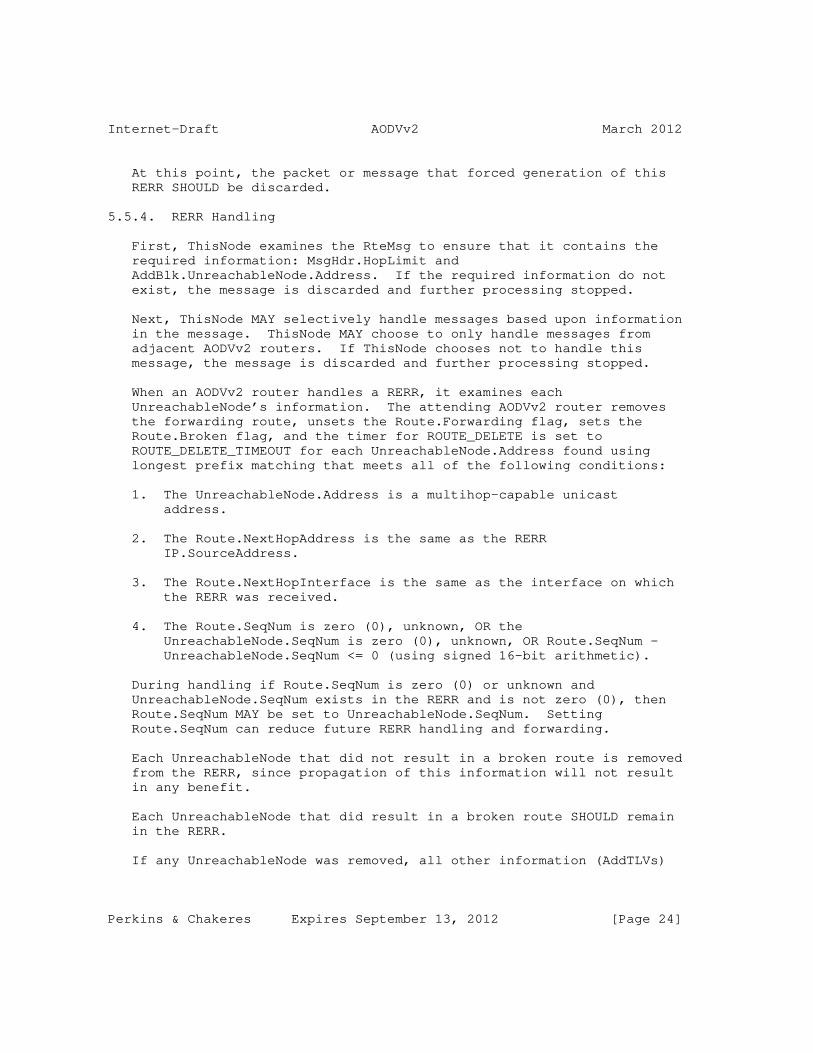
Internet-Draft AODVv2 March 2012
At this point, the packet or message that forced generation of this RERR SHOULD be discarded.
5.5.4. RERR Handling
First, ThisNode examines the RteMsg to ensure that it contains the required information: MsgHdr.HopLimit and AddBlk.UnreachableNode.Address. If the required information do not exist, the message is discarded and further processing stopped.
Next, ThisNode MAY selectively handle messages based upon information in the message. ThisNode MAY choose to only handle messages from adjacent AODVv2 routers. If ThisNode chooses not to handle this message, the message is discarded and further processing stopped.
When an AODVv2 router handles a RERR, it examines each UnreachableNode’s information. The attending AODVv2 router removes the forwarding route, unsets the Route.Forwarding flag, sets the Route.Broken flag, and the timer for ROUTE_DELETE is set to ROUTE_DELETE_TIMEOUT for each UnreachableNode.Address found using longest prefix matching that meets all of the following conditions:
1. The UnreachableNode.Address is a multihop-capable unicast address.
2. The Route.NextHopAddress is the same as the RERR IP.SourceAddress.
3. The Route.NextHopInterface is the same as the interface on which the RERR was received.
4. The Route.SeqNum is zero (0), unknown, OR the UnreachableNode.SeqNum is zero (0), unknown, OR Route.SeqNum - UnreachableNode.SeqNum <= 0 (using signed 16-bit arithmetic).
During handling if Route.SeqNum is zero (0) or unknown and UnreachableNode.SeqNum exists in the RERR and is not zero (0), then Route.SeqNum MAY be set to UnreachableNode.SeqNum. Setting Route.SeqNum can reduce future RERR handling and forwarding.
Each UnreachableNode that did not result in a broken route is removed from the RERR, since propagation of this information will not result in any benefit.
Each UnreachableNode that did result in a broken route SHOULD remain in the RERR.
If any UnreachableNode was removed, all other information (AddTLVs)
Perkins & Chakeres Expires September 13, 2012 [Page 24]
Internet-Draft AODVv2 March 2012
associated with the removed address(es) MUST also be removed.
After handling if Route.SeqNum is known and an UnreachableNode.SeqNum is not included in the RERR, then Route.SeqNum (i.e. UnreachableNode.SeqNum) MAY be added to the RERR. Including UnreachableNode.SeqNum can reduce future RERR handling and forwarding.
If no UnreachableNode addresses remain in the RERR, no other handling is required and the RERR is discarded.
If handling continues, the MsgHdr.HopLimit is decremented by one (1). Further, if this RERR’s new MsgHdr.HopLimit is greater than one (1) and at least one unreachable node address remains in the RERR, then the updated RERR SHOULD be sent.
A multicast RERR is sent to the IP.DestinationAddress LL-MANET- Routers [RFC5498]. If the RERR is unicast, the IP.DestinationAddress is set to the NextHopAddress.
5.6. Unknown Message and TLV Types
If a message with an unknown type is received, the message is discarded.
For handling of messages that contain unknown TLV types, the default behavior is to leave the information in control messages unmodified. Although, this behavior (UNKNOWN_TYPES) MAY be administratively controlled.
5.7. Advertising Network Addresses
AODVv2 routers specify the prefix length for each advertised address. Any nodes (other than the advertising AODVv2 router) within the advertised prefix MUST NOT participate in the AODVv2 protocol directly. For example, advertising 192.0.2.1 with a prefix length of 24 indicates that all nodes with the matching 192.0.2.X are reachable through this AODVv2 router.
5.8. Simple Internet Attachment
Simple Internet attachment consists of a stub network of AODVv2 routers connected to the Internet via a single Internet AODVv2 router (IDR).
AODVv2 routers, and hosts behind these routers, wishing to be reachable from hosts on the Internet MUST have IP addresses within the IDR’s routable and topologically correct prefix (e.g.
Perkins & Chakeres Expires September 13, 2012 [Page 25]

Internet-Draft AODVv2 March 2012
192.0.2.0/24).
The IDR is responsible for generating RREQ to find nodes within the AODVv2 Region on behalf of nodes on the Internet, as well as responding to route requests from the AODVv2 region on behalf of the nodes on the Internet.
/--------------------------\ / Internet \ \ / \------------+-------------/ | Routable & | Topologically | Correct | Prefix | +-----+------+ | Internet | /------| AODVv2 |-------\ / | Router | \ / |192.0.2.1/32| \ | |Responsible | | | | for | | | |AODVv2 Region | | | |192.0.2.0/24| | | +------------+ | | +--------------+ | | | AODVv2 Router | | | | 192.0.2.2/32 | | | +--------------+ | | +--------------+ | | | AODVv2 Router | | | | 192.0.2.3/32 | | \ +--------------+ / \ / \---------------------------/
Figure 1: Simple Internet Attachment Example
When an AODVv2 router within the AODVv2 Region wants to discover a route to a node on the Internet, it uses the normal AODVv2 route discovery for that IP Destination Address. The IDR is responsible for properly responding to RREQ on behalf of the Internet destination.
When a packet from a node on the Internet destined for a node in the AODVv2 region reaches the IDR, if the IDR does not have a route to that destination it will perform normal AODVv2 route discovery for
Perkins & Chakeres Expires September 13, 2012 [Page 26]

Internet-Draft AODVv2 March 2012
that destination.
5.9. Multiple Interfaces
AODVv2 may be used with multiple interfaces; therefore, the particular interface over which packets arrive MUST be known whenever a packet is received. Whenever a new route is created, the interface through which the Route.Address can be reached is also recorded in the route table entry.
When multiple interfaces are available, a node transmitting a multicast packet with IP.DestinationAddress set to LL-MANET-Routers SHOULD send the packet on all interfaces that have been configured for AODVv2 operation.
Similarly, AODVv2 routers should subscribe to LL-MANET-Routers on all their AODVv2 interfaces.
5.10. AODVv2 Control Packet/Message Generation Limits
To ensure predictable control overhead, AODVv2 router’s rate of packet/message generation SHOULD be limited. The rate and algorithm for limiting messages (CONTROL_TRAFFIC_LIMITS) is left to the implementor and should be administratively configurable or intelligently controlled. AODVv2 control messages SHOULD be discarded in the following order of preference: RREQ, RREP, and finally RERR.
6. Administratively Configured Parameters and Timer Values
AODVv2 contains several parameters which MUST be administratively configured. The list of these follows:
Required Administratively Configured Parameters
+------------------------+------------------------------------------+ | Name | Description | +------------------------+------------------------------------------+ | RESPONSIBLE_ADDRESSES | List of addresses or routing prefixes, | | | for which this AODVv2 router is | | | responsible. If, RESPONSIBLE_ADDRESSES | | | is zero, this AODVv2 router is only | | | responsible for its own addresses. | | AODVv2_INTERFACES | List of the interfaces participating in | | | AODVv2 routing protocol. | +------------------------+------------------------------------------+
Perkins & Chakeres Expires September 13, 2012 [Page 27]

Internet-Draft AODVv2 March 2012
Table 2
AODVv2 contains a number of timers. The default timing parameter values follow:
Default Timing Parameter Values
+------------------------------+-------------------+ | Name | Value | +------------------------------+-------------------+ | ROUTE_TIMEOUT | 5 seconds | | ROUTE_AGE_MIN_TIMEOUT | 1 second | | ROUTE_SEQNUM_AGE_MAX_TIMEOUT | 60 seconds | | ROUTE_USED_TIMEOUT | ROUTE_TIMEOUT | | ROUTE_DELETE_TIMEOUT | 2 * ROUTE_TIMEOUT | | ROUTE_RREQ_WAIT_TIME | 2 seconds | | UNICAST_MESSAGE_SENT_TIMEOUT | 1 second | +------------------------------+-------------------+
Table 3
The above timing parameter values work well for small and medium well-connected networks with moderate topology changes.
The timing parameters SHOULD be administratively configurable for the network where AODVv2 is used. Ideally, for networks with frequent topology changes the AODVv2 parameters should be adjusted using either experimentally determined values or dynamic adaptation. For example, in networks with infrequent topology changes ROUTE_USED_TIMEOUT may be set to a much larger value.
Default Parameter Values
+------------------------+-------+----------------------------------+ | Name | Value | Description | +------------------------+-------+----------------------------------+ | MSG_HOPLIMIT | 10 | This value MUST be larger than | | | hops | the AODVv2 network diameter. | | | | Otherwise, routing messages may | | | | not reach their intended | | | | destinations. | | DISCOVERY_ATTEMPTS_MAX | 3 | The number of route discovery | | | | attempts to make before | | | | indicating that a particular | | | | address is not reachable. | +------------------------+-------+----------------------------------+
Table 4
Perkins & Chakeres Expires September 13, 2012 [Page 28]

Internet-Draft AODVv2 March 2012
In addition to the above parameters and timing values, several administrative options exist. These options have no influence on correct routing behavior, although they may potentially reduce AODVv2 routing control messaging in certain situations. The default behavior is to NOT enable any of these options; and although many of these options can be administratively controlled, they may be better served by intelligent control. The following table enumerates several of the options.
Administratively Controlled Options
+-------------------------+-----------------------------------------+ | Name | Description | +-------------------------+-----------------------------------------+ | BUFFER_DURING_DISCOVERY | Whether and how much data to buffer | | | during route discovery. | | UNKNOWN_TYPES | What action to take when an unknown TLV | | | type is received. The default action | | | is to forward this information | | | unmodified. Another action would be to | | | remove this information. | | CONTROL_TRAFFIC_LIMITS | AODVv2 control messaging SHOULD be | | | limited to avoid consuming all the | | | network bandwidth. | +-------------------------+-----------------------------------------+
Table 5
Note: several fields have limited size (bits or bytes) these sizes and their encoding may place specific limitations on the values that can be set. For example, MsgHdr.HopLimit is a 8-bit field and therefore MSG_HOPLIMIT cannot be larger than 255.
7. IANA Considerations
In its default mode of operation, AODVv2 uses the UDP port MANET [RFC5498] to carry protocol packets. AODVv2 also uses the link-local multicast address LL-MANET-Routers [RFC5498].
This section specifies several message types, message tlv-types, and address tlv-types.
Perkins & Chakeres Expires September 13, 2012 [Page 29]

Internet-Draft AODVv2 March 2012
7.1. AODVv2 Message Types Specification
AODVv2 Message Types
+------------------------+----------+ | Name | Type | +------------------------+----------+ | Route Request (RREQ) | 10 - TBD | | Route Reply (RREP) | 11 - TBD | | Route Error (RERR) | 12 - TBD | +------------------------+----------+
Table 6
7.2. Message and Address Block TLV Type Specification
Message TLV Types
+-------------------+------+--------+-------------------------------+ | Name | Type | Length | Value | +-------------------+------+--------+-------------------------------+ | Unicast Response | 10 - | 0 | Indicates to the processing | | Request | TBD | octets | node that the previous hop | | | | | (IP.SourceAddress) expects a | | | | | unicast message within | | | | | UNICAST_MESSAGE_SENT_TIMEOUT. | | | | | Any unicast packet will serve | | | | | this purpose, and it MAY be | | | | | an ICMP REPLY message. If a | | | | | message is not sent, then the | | | | | previous hop can assume that | | | | | the link is unidirectional | | | | | and MAY blacklist the link to | | | | | this node. | +-------------------+------+--------+-------------------------------+
Table 7
Perkins & Chakeres Expires September 13, 2012 [Page 30]

Internet-Draft AODVv2 March 2012
7.3. Address Block TLV Specification
Address Block TLV Types
+----------------+------------+----------+--------------------------+ | Name | Type | Length | Value | +----------------+------------+----------+--------------------------+ | AODVv2 | 10 - TBD | up to 2 | The AODVv2 sequence num | | Sequence | | octets | associated with this | | Number | | | address. The sequence | | (AODVv2SeqNum) | | | number may be the last | | | | | known sequence number. | | Distance | 11 - TBD | up to 2 | A metric of the distance | | | | octets | traversed by the | | | | | information associated | | | | | with this address. | | VALIDITY_TIME | 1[RFC5497] | | The maximum amount of | | | | | time that information | | | | | can be maintained before | | | | | being deleted. The | | | | | VALIDITY_TIME TLV is | | | | | defined in [RFC5497]. | +----------------+------------+----------+--------------------------+
Table 8
8. Security Considerations
The objective of the AODVv2 protocol is for each router to communicate reachability information to addresses for which it is responsible. Positive routing information (i.e. a route exists) is distributed via RteMsgs and negative routing information (i.e. a route does not exist) via RERRs. AODVv2 routers that handle these messages store the contained information to properly forward data packets, and they generally provide this information to other AODVv2 routers.
This section does not mandate any specific security measures. Instead, this section describes various security considerations and potential avenues to secure AODVv2 routing.
The most important security mechanisms for AODVv2 routing are integrity/authentication and confidentiality.
In situations where routing information or router identity are suspect, integrity and authentication techniques SHOULD be applied to AODVv2 messages. In these situations, routing information that is
Perkins & Chakeres Expires September 13, 2012 [Page 31]

Internet-Draft AODVv2 March 2012
distributed over multiple hops SHOULD also verify the integrity and identity of information based on originator of the routing information.
A digital signature could be used to identify the source of AODVv2 messages and information, along with its authenticity. A nonce or timestamp SHOULD also be used to protect against replay attacks. S/MIME and OpenPGP are two authentication/integrity protocols that could be adapted for this purpose.
In situations where confidentiality of AODVv2 messages is important, cryptographic techniques can be applied.
In certain situations, like sending a RREP or RERR, an AODVv2 router could include proof that it has previously received valid routing information to reach the destination, at one point of time in the past. In situations where routers are suspected of transmitting maliciously erroneous information, the original routing information along with its security credentials SHOULD be included.
Note that if multicast is used, any confidentiality and integrity algorithms used must permit multiple receivers to handle the message.
9. Acknowledgments
AODVv2 is a descendant of the design of previous MANET on-demand protocols, especially AODV [RFC3561] and DSR [RFC4728]. Changes to previous MANET on-demand protocols stem from research and implementation experiences. Thanks to Elizabeth Belding-Royer for her long time authorship of AODVv2. Additional thanks to Luke Klein- Berndt, Pedro Ruiz, Fransisco Ros, Koojana Kuladinithi, Ramon Caceres, Thomas Clausen, Christopher Dearlove, Seung Yi, Romain Thouvenin, Tronje Krop, Henner Jakob, Alexandru Petrescu, Christoph Sommer, Cong Yuan, Lars Kristensen, and Derek Atkins for reviewing of AODVv2, as well as several specification suggestions.
Many good ideas from LOADng [I-D.clausen-lln-loadng] are shaping this evolution of the [manet] reactive routing protocol specification. Thanks are due to T. Clausen, A. Colin de Verdiere, J. Yi, A. Niktash, Y. Igarashi, SATOH. H., and U. Herberg for their development of LOADng and sharing details for ensuring appropriateness of AODVv2 for LLNs.
10. References
Perkins & Chakeres Expires September 13, 2012 [Page 32]

Internet-Draft AODVv2 March 2012
10.1. Normative References
[RFC1812] Baker, F., "Requirements for IP Version 4 Routers", RFC 1812, June 1995.
[RFC2119] Bradner, S., "Key words for use in RFCs to Indicate Requirement Levels", BCP 14, RFC 2119, March 1997.
[RFC5082] Gill, V., Heasley, J., Meyer, D., Savola, P., and C. Pignataro, "The Generalized TTL Security Mechanism (GTSM)", RFC 5082, October 2007.
[RFC5444] Clausen, T., Dearlove, C., Dean, J., and C. Adjih, "Generalized Mobile Ad Hoc Network (MANET) Packet/Message Format", RFC 5444, February 2009.
[RFC5497] Clausen, T. and C. Dearlove, "Representing Multi-Value Time in Mobile Ad Hoc Networks (MANETs)", RFC 5497, March 2009.
[RFC5498] Chakeres, I., "IANA Allocations for Mobile Ad Hoc Network (MANET) Protocols", RFC 5498, March 2009.
10.2. Informative References
[I-D.chakeres-manet-manetid] Chakeres, I., "MANET_ID TLV", draft-chakeres-manet-manetid-03 (work in progress), February 2008.
[I-D.clausen-lln-loadng] Clausen, T., Verdiere, A., Yi, J., Niktash, A., Igarashi, Y., and U. Herberg, "The LLN On-demand Ad hoc Distance- vector Routing Protocol - Next Generation (LOADng)", draft-clausen-lln-loadng-01 (work in progress), October 2011.
[I-D.ietf-manet-nhdp] Clausen, T., Dearlove, C., and J. Dean, "Mobile Ad Hoc Network (MANET) Neighborhood Discovery Protocol (NHDP)", draft-ietf-manet-nhdp-15 (work in progress), December 2010.
[I-D.ietf-ospf-multi-instance] Lindem, A., Roy, A., and S. Mirtorabi, "OSPFv2 Multi- Instance Extensions", draft-ietf-ospf-multi-instance-09 (work in progress), January 2012.
Perkins & Chakeres Expires September 13, 2012 [Page 33]

Internet-Draft AODVv2 March 2012
[Perkins99] Perkins, C. and E. Belding-Royer, "Ad hoc On-Demand Distance Vector (AODV) Routing", Proceedings of the 2nd IEEE Workshop on Mobile Computing Systems and Applications, New Orleans, LA, pp. 90-100, February 1999.
[RFC2328] Moy, J., "OSPF Version 2", STD 54, RFC 2328, April 1998.
[RFC3561] Perkins, C., Belding-Royer, E., and S. Das, "Ad hoc On- Demand Distance Vector (AODV) Routing", RFC 3561, July 2003.
[RFC4728] Johnson, D., Hu, Y., and D. Maltz, "The Dynamic Source Routing Protocol (DSR) for Mobile Ad Hoc Networks for IPv4", RFC 4728, February 2007.
[RFC4861] Narten, T., Nordmark, E., Simpson, W., and H. Soliman, "Neighbor Discovery for IP version 6 (IPv6)", RFC 4861, September 2007.
[RFC5148] Clausen, T., Dearlove, C., and B. Adamson, "Jitter Considerations in Mobile Ad Hoc Networks (MANETs)", RFC 5148, February 2008.
[RFC5340] Coltun, R., Ferguson, D., Moy, J., and A. Lindem, "OSPF for IPv6", RFC 5340, July 2008.
Appendix A. Changes since the Previous Version
o Protocol renamed to be AODVv2
o Intermediate RREPs (iRREPs) are to be put into new document. Without iRREP, only the destination can respond to a RREQ.
o Precursor lists not supported, based on reported performance loss.
o Routing Messages MUST be originated with the MsgHdr.HopLimit set to MSG_HOPLIMIT. Previously, this was not mandated.
o Adding additional unreachable destinations to RERR is not specified in this document, to match LOADng behavior.
Appendix B. Proposed additional changes for LOADng conformance
Perkins & Chakeres Expires September 13, 2012 [Page 34]

Internet-Draft AODVv2 March 2012
o Revise message formats to be compatible with LOADng requirements, removing RFC 5444 headers for minimal packet size
o Adding RREP-ACK message type instead of relying on reception of arbitrary packets as sufficient response to establish bidirectionality.
Appendix C. Shifting Responsibility for an Address Between AODVv2 Routers
Only one AODVv2 router within a routing region SHOULD be responsible for a particular address at any time. If two AODVv2 routers dynamically pass responsibility of an address correct AODVv2 routing behavior must be observed. The AODVv2 router adding the new address must wait for any exiting routing information about this address to be purged from the network. Therefore, it must wait at least ROUTER_SEQNUM_AGE_MAX_TIMEOUT after the previous AODVv2 router for this address stopped participating and advertising routing information on its behalf.
Authors’ Addresses
Charles E. Perkins Central Expressway San Jose, CA 95050 USA
Phone: +1-408-421-1172 Email: [email protected]
Ian D Chakeres CenGen 9250 Bendix Road North Columbia, Maryland 21045 USA
Email: [email protected] URI: http://www.ianchak.com/
Perkins & Chakeres Expires September 13, 2012 [Page 35]


Internet Engineering Task Force U. HerbergInternet-Draft LIX, Ecole PolytechniqueIntended status: Standards Track R. ColeExpires: July 9, 2012 US Army CERDEC I. Chakeres CenGen January 6, 2012
Definition of Managed Objects for the Neighborhood Discovery Protocol draft-ietf-manet-nhdp-mib-11
Abstract
This memo defines a portion of the Management Information Base (MIB) for use with network management protocols in the Internet community. In particular, it describes objects for configuring parameters of the Neighborhood Discovery Protocol (NHDP) process on a router. The MIB defined in this memo, denoted NHDP-MIB, also reports state, performance information and notifications. This additional state and performance information is useful to troubleshoot problems and performance issues during neighbor discovery.
Status of This Memo
This Internet-Draft is submitted in full conformance with the provisions of BCP 78 and BCP 79.
Internet-Drafts are working documents of the Internet Engineering Task Force (IETF). Note that other groups may also distribute working documents as Internet-Drafts. The list of current Internet- Drafts is at http://datatracker.ietf.org/drafts/current/.
Internet-Drafts are draft documents valid for a maximum of six months and may be updated, replaced, or obsoleted by other documents at any time. It is inappropriate to use Internet-Drafts as reference material or to cite them other than as "work in progress."
This Internet-Draft will expire on July 9, 2012.
Copyright Notice
Copyright (c) 2012 IETF Trust and the persons identified as the document authors. All rights reserved.
This document is subject to BCP 78 and the IETF Trust’s Legal Provisions Relating to IETF Documents (http://trustee.ietf.org/license-info) in effect on the date of
Herberg, et al. Expires July 9, 2012 [Page 1]
Internet-Draft The NHDP-MIB January 2012
publication of this document. Please review these documents carefully, as they describe your rights and restrictions with respect to this document. Code Components extracted from this document must include Simplified BSD License text as described in Section 4.e of the Trust Legal Provisions and are provided without warranty as described in the Simplified BSD License.
Table of Contents
1. Introduction . . . . . . . . . . . . . . . . . . . . . . . . . 3 2. The Internet-Standard Management Framework . . . . . . . . . . 3 3. Conventions . . . . . . . . . . . . . . . . . . . . . . . . . 3 4. Overview . . . . . . . . . . . . . . . . . . . . . . . . . . . 3 4.1. Terms . . . . . . . . . . . . . . . . . . . . . . . . . . 3 5. Structure of the MIB Module . . . . . . . . . . . . . . . . . 4 5.1. Notifications . . . . . . . . . . . . . . . . . . . . . . 4 5.1.1. Introduction . . . . . . . . . . . . . . . . . . . . . 4 5.1.2. Notification Generation . . . . . . . . . . . . . . . 5 5.1.3. Limiting Frequency of Notifications . . . . . . . . . 5 5.2. The Configuration Group . . . . . . . . . . . . . . . . . 5 5.3. The State Group . . . . . . . . . . . . . . . . . . . . . 6 5.4. The Performance Group . . . . . . . . . . . . . . . . . . 6 6. Relationship to Other MIB Modules . . . . . . . . . . . . . . 15 6.1. Relationship to the SNMPv2-MIB . . . . . . . . . . . . . . 15 6.2. Relationship to Routing Protocol MIBs Relying on the NHDP-MIB . . . . . . . . . . . . . . . . . . . . . . . . . 15 6.3. MIB Modules Required for IMPORTS . . . . . . . . . . . . . 16 7. Definitions . . . . . . . . . . . . . . . . . . . . . . . . . 16 8. Security Considerations . . . . . . . . . . . . . . . . . . . 63 9. IANA Considerations . . . . . . . . . . . . . . . . . . . . . 65 10. Contributors . . . . . . . . . . . . . . . . . . . . . . . . . 65 11. Acknowledgements . . . . . . . . . . . . . . . . . . . . . . . 65 12. References . . . . . . . . . . . . . . . . . . . . . . . . . . 65 12.1. Normative References . . . . . . . . . . . . . . . . . . . 65 12.2. Informative References . . . . . . . . . . . . . . . . . . 66 Appendix A. . . . . . . . . . . . . . . . . . . . . . . . . . . 66
Herberg, et al. Expires July 9, 2012 [Page 2]

Internet-Draft The NHDP-MIB January 2012
1. Introduction
This memo defines a portion of the Management Information Base (MIB) for use with network management protocols in the Internet community. In particular, it describes objects for configuring parameters of the Neighborhood Discovery Protocol [RFC6130] process on a router. The MIB defined in this memo, denoted NHDP-MIB, also reports state, performance information and notifications. This additional state and performance information is useful to troubleshoot problems and performance issues during neighbor discovery.
2. The Internet-Standard Management Framework
For a detailed overview of the documents that describe the current Internet-Standard Management Framework, please refer to Section 7 of [RFC3410].
Managed objects are accessed via a virtual information store, termed the Management Information Base or MIB. MIB objects are generally accessed through the Simple Network Management Protocol (SNMP). Objects in the MIB are defined using the mechanisms defined in the Structure of Management Information (SMI). This memo specifies a MIB module that is compliant to the SMIv2, which is described in [RFC2578], [RFC2579] and [RFC2580].
3. Conventions
The key words "MUST", "MUST NOT", "REQUIRED", "SHALL", "SHALL NOT", "SHOULD", "SHOULD NOT", "RECOMMENDED", "NOT RECOMMENDED", "MAY", and OPTIONAL" in this document are to be interpreted as described in [RFC2119].
4. Overview
[RFC6130] allows a router in a Mobile Ad Hoc Network (MANET) to discover and track topological information of routers up to two hops away by virtue of exchanging HELLO messages. This information is useful for routers running various routing and multicast flooding protocols developed within the IETF MANET Working Group.
4.1. Terms
The following definitions apply throughout this document:
o Notification Objects - triggers and associated notification messages allowing for asynchronous tracking of pre-defined events on the managed router.
Herberg, et al. Expires July 9, 2012 [Page 3]

Internet-Draft The NHDP-MIB January 2012
o Configuration Objects - switches, tables, objects which are initialized to default settings or set through the management interface defined by this MIB.
o State Objects - automatically generated values which define the current operating state of the NHDP protocol process in the router.
o Performance Objects - automatically generated values which help an administrator or automated tool to assess the performance of the NHDP protocol process on the router and the overall discovery performance within the MANET.
5. Structure of the MIB Module
This section presents the structure of the NHDP-MIB module. The MIB is arranged into the following structure:
o nhdpNotifications - objects defining NHDP-MIB notifications.
o nhdpObjects - defining objects within this MIB. The objects are arranged into the following groups:
* Configuration Group - defining objects related to the configuration of the NHDP instance on the router.
* State Group - defining objects which reflect the current state of the NHDP instance running on the router.
* Performance Group - defining objects which are useful to a management station when characterizing the performance of NHDP on the router and in the MANET.
o nhdpConformance - defining the minimal and maximal conformance requirements for implementations of this MIB.
5.1. Notifications
This section describes the use of notifications, and mechanisms to enhance the ability to manage NHDP networks.
5.1.1. Introduction
Notifications can be emitted by an NHDP router as a reaction to a specific event. This allows a network manager to efficiently determine the source of problems or significant changes of configuration or topology, instead of polling a possibly large number of NHDP routers.
Herberg, et al. Expires July 9, 2012 [Page 4]

Internet-Draft The NHDP-MIB January 2012
5.1.2. Notification Generation
When an exception event occurs, the application notifies the local agent, which sends a notification to the appropriate SNMP management stations. The message includes the notification type and may include a list of notification-specific variables. Section 7 contains the notification definitions, which includes the variable lists. At least one IP address of the NHDP router that originates the notification is included in the variable list so that the network manager may determine the source of the notification.
5.1.3. Limiting Frequency of Notifications
To limit the frequency of notifications, the following additional mechanisms are suggested, similar to those in [RFC4750]:
5.1.3.1. Ignoring Initial Activity
The majority of critical events occur when NHDP is enabled on a router, at which time the symmetric neighbors and two-hop neighbors of the NHDP router are discovered. During this initial period, a potential flood of notifications is unnecessary since the events are expected. To avoid unnecessary notifications, a router should not originate expected notifications until a certain time interval has elapsed, which is to be predefined by the network manager.
5.1.3.2. Throttling Traps
The mechanism for throttling the notifications is the same as in [RFC4750] (i.e. the amount of transmitted notifications per time is bounded).
Appropriate values for the window time and upper bound are to be selected by the network manager and depend on the deployment of the MANET.
5.1.3.3. One Notification per Event
Similar to the according mechanism in [RFC4750], only one notification is sent per event.
5.2. The Configuration Group
The NHDP router is configured with a set of controls. The authoritative list of configuration controls within the NHDP-MIB are found within the MIB module itself. Generally, an attempt was made in developing the NHDP-MIB module to support all configuration objects defined in [RFC6130]. For all of the configuration
Herberg, et al. Expires July 9, 2012 [Page 5]

Internet-Draft The NHDP-MIB January 2012
parameters, the same constraints and default values of these parameters as defined in [RFC6130] are followed. Refer to [RFC5148] for guidance on setting jitter related parameters, e.g., nhdpMaxJitter.
5.3. The State Group
The State Group reports current state information of a router running [RFC6130]. The NHDP-MIB State Group tables were designed to contain the complete set of state information defined within the information bases specified in Section 6, Section 7 and Section 8 of [RFC6130].
Two constructs, i.e., TEXTUAL CONVENTIONs, are defined to support of the tables in the State Group. The NHDP protocol stores and indexes information through sets of (dynamically defined) addresses, i.e., address sets. Within SMIv2 it is not possible to index tables with variably defined address sets. Hence, these TEXTUAL CONVENTIONS are defined to provide a local mapping between NHDP managed address sets and SMIv2 table indexing. These constructs are the NeighborIfIndex and NeighborRouterIndex. These are locally (to the NHDP router) defined, unique identifiers of virtual neighbors and neighbor interfaces. Due to the nature of the NHDP protocol, the local router may have identified distinct address sets but is not able to associate these as a single interface. Hence, two or more NeighborIfIndexes pointing to multiple distinct address sets may in fact be related to a common neighbor interface. This ambiguity may also hold with respect to the assignment of the NeighborRouterIndex. The local MIB agent is responsible for managing, aggregating and retiring the defined indexes, and in updating MIB tables using these indexes as the local router learns more about its neighbors’ topology. These constructs are used to define indexes to the appropriate State Group tables and to correlate table entries to address sets, virtual neighbor interfaces and virtual neighbors within the MANET.
5.4. The Performance Group
The Performance Group reports values relevant to system performance. This section lists objects for NHDP performance monitoring, some of which are explicitly defined in the NHDP-MIB and others which can be estimated through a combination of base objects from this MIB. Throughout this section, those objects will be pointed out that are intended as base objects which are explicitly defined within this MIB and those objects which can be estimated.
Unstable neighbors or 2-hop neighbors and frequent changes of sets can have a negative influence on the performance of NHDP. The following objects allow management applications to acquire
Herberg, et al. Expires July 9, 2012 [Page 6]

Internet-Draft The NHDP-MIB January 2012
information related to the stability and performance of NHDP:
The following objects return statistics related to HELLO messages:
o Total number of sent HELLO messages on an interface
This is a Base Object.
Object name: nhdpIfHelloMessageXmits
Object type: Counter32
o Total number of received HELLO messages on an interface
This is a Base Object.
Object name: nhdpIfHelloMessageRecvd
Object type: Counter32
o Total number of sent periodic HELLO messages on an interface
This is a Base Object.
Object name: nhdpIfHelloMessagePeriodicXmits
Object type: Counter32
o Total number of sent triggered HELLO messages on an interface
This is a Base Object.
Object name: nhdpIfHelloMessageTriggeredXmits
Object type: Counter32
o Acquire history of HELLO message scheduling instances for a given time duration on an interface
It is desirable to develop the history of the exact timestamps of each HELLO message that has been sent as well as the type of the message (triggered or periodical). The list of events starts at the given point of time t0 and ends at the given time t1.
Herberg, et al. Expires July 9, 2012 [Page 7]

Internet-Draft The NHDP-MIB January 2012
This is a Derived Object estimated from the NHDP-MIB. It is derived from, e.g., the nhdpIfHelloMessagePeriodicXmits Base Object from the NHDP-MIB.
o Histogram of the intervals between HELLO messages on an interface
It is desirable to track the values (in a 2-dimensional array) that represent a histogram of intervals between HELLO messages. The histogram would display the distribution of intervals between two consecutive HELLOs using a given bin size. It includes all HELLOs that have been sent after the given time t0 and before the given time t1.
This is a Derived Object to be estimated from objects within the NHDP-MIB. It can be estimated from, e.g., the nhdpIfHelloMessagePeriodicXmits Base Object from the NHDP-MIB. The network management application could convert this information into the desired histogram.
o Changes of the frequency of the message scheduling on an interface
This object will divide the given time interval from t0 to t1 into a given number of equal parts. It then creates a histogram for each part and calculates the distances (e.g. using the Bhattacharyya distance) between each two adjacent histograms in time. A higher value between two histograms means more difference between the histograms. For instance, this is representative of an event that suddenly sends many triggered HELLO messages, whereas before there have been only very few such triggered messages.
This is a Derived Object estimated from objects within the NHDP-MIB, as previously discussed, albeit this is a bit more complex with respect to the management application.
o Average number of sent HELLO messages per second between the given time t0 and t1 on an interface
This is a Derived Object estimated from, e.g., the nhdpIfHelloMessageXmits Base Object.
o Average number of received HELLO messages per second on an interface between the given time t0 and t1
This is a Derived Object estimated from the NHDP-MIB. See the previous discussion.
Herberg, et al. Expires July 9, 2012 [Page 8]

Internet-Draft The NHDP-MIB January 2012
o Total accumulated size in octets of sent HELLO messages on an interface
This is a Base Object.
Object name: nhdpIfHelloMessageXmitAccumulatedSize
Object type: Counter64
o Total accumulated size in octets of received HELLO messages on an interface
This is a Base Object.
Object name: nhdpIfHelloMessageRecvdAccumulatedSize
Object type: Counter64
o Average size in octets of sent HELLO messages between the given time t0 and t1 on an interface
This is a Derived Object estimated from, e.g., the nhdpIfHelloMessageRecvdAccumulatedSize Base Object from this NHDP-MIB.
o Average size in octets of received HELLO messages between the given time t0 and t1 on an interface
This is a Derived Object estimated from the NHDP-MIB. See previous discussion.
o Total accumulated number of advertised symmetric neighbors in HELLOs on that interface.
This is a Base Object.
Object name: nhdpIfHelloMessageXmitAccumulatedSymmetricNeighborCount
Object type: Counter32
o Total accumulated number of advertised heard neighbors in HELLOs on that interface
This is a Base Object.
Herberg, et al. Expires July 9, 2012 [Page 9]

Internet-Draft The NHDP-MIB January 2012
Object name: nhdpIfHelloMessageXmitAccumulatedHeardNeighborCount
Object type: Counter32
o Total accumulated number of advertised lost neighbors in HELLOs on that interface
This is a Base Object.
Object name: nhdpIfHelloMessageXmitAccumulatedLostNeighborCount
Object type: Counter32
o Number of expected packets from a given neighbor based on the packet sequence number on an interface
This is a Base Object.
Object name: nhdpDiscIfExpectedPackets
Object type: Counter32
o Success rate of received packets (number of received packets divided by number of expected packets based on the packet sequence number)
This is a Derived Object to be pulled from this NHDP-MIB. It is derived from, e.g., the nhdpDiscIfRecvdPackets and the nhdpDiscIfExpectedPackets Base Objects defined in this MIB. This metric is then computed by the network management application.
The following objects inspect the frequency of all Neighbor Set changes:
o Number of Neighbor Set changes
This object counts each Neighbor Set change. A change occurs whenever a new Neighbor Tuple has been added, a Neighbor Tuple has been removed or any entry of a Neighbor Tuple has been modified.
This is a Base Object.
Herberg, et al. Expires July 9, 2012 [Page 10]
Internet-Draft The NHDP-MIB January 2012
Object name: nhdpNibNeighborSetChanges
Object type: Counter32
o Acquire history of Neighbor Set changes
This object returns the history of the exact timestamps of each time the Neighbor Set has been changed.
This is a Derived Object estimated from the NHDP-MIB. It is derived from the previously discussed Base Object.
o Histogram of the intervals between Neighbor Set changes
Returns the values (in a 2-dimensional array) that represent a histogram of intervals between Neighbor Set changes.
This is a Derived Object estimated from the previously discussed Base Object.
o Changes of the frequency of the Neighbor Set changes
This object will divide the given time interval from t0 to t1 into a given number of equal parts. It then creates a histogram for each part and calculates the distances (e.g. using the Bhattacharyya distance) between each two adjacent histograms in time. A higher value between two histograms means more difference between the histograms.
This is a Derived Object estimated from the previously discussed Base Object.
The next objects examine the uptime of a given neighbor (as listed in the Neighbor Set):
o Number of changes of a Neighbor Tuple
Returns the number of changes to the given Neighbor Tuple.
This is a Base Object.
Object name: nhdpDiscNeighborNibNeighborSetChanges
Object type: Counter32
o Neighbor uptime
Herberg, et al. Expires July 9, 2012 [Page 11]

Internet-Draft The NHDP-MIB January 2012
Returns the number of hundredths of a second since the Neighbor Tuple corresponding to the given neighbor exists.
This is a Base Object.
Object name: nhdpDiscNeighborNibNeighborSetUpTime
Object type: TimeTicks
o Acquire history of change of the ’nbrup’ status of a given neighbor
This object returns the history of the exact timestamps of each time the neighbor (as listed in the Neighbor Set) becomes ’nbrup’ or ’nbrdown’. A neighbor is said to become ’nbrup’ if a new Neighbor Tuple is created that corresponds to the given neighbor. It becomes ’nbrdown’ if such a Neighbor Tuple has been deleted. The existence of a Lost Neighbor Tuple for that previous neighbor does not mean that the neighbor is still ’nbrup’.
This is a Derived Object estimated from, e.g., the nhdpDiscNeighborNibNeighborSetChanges Base Object defined in this MIB.
o Histogram of the intervals between a change of the ’nbrup’ status of a given neighbor
Returns the values that represent a histogram of intervals between a change of the ’nbrup’ status of a given neighbor. The histogram includes all changes that have been made after the given time t0 and before the given time t1.
This is a Derived Object estimated from, e.g. the nhdpDiscNeighborNibNeighborSetChanges Base Object defined in this MIB. This object sits in the nhdpDiscNeighborSetPerfTable which is indexed by the nhdpDiscRouterIndex.
The following objects examine the stability of a neighbor. A neighbor is said to be unstable if it ’flaps’ frequently between several links. It is said to be stable if the set of Link Tuples that correspond to the given neighbor is stationary.
o Count the changes of the interface(s) over which a given neighbor (as listed in the Neighbor Set) can be reached
Herberg, et al. Expires July 9, 2012 [Page 12]
Internet-Draft The NHDP-MIB January 2012
This object counts each time the neighbor changes the interface(s) over which it is reachable. A change in the set of Link Tuples corresponding to the appropriate Neighbor Tuple is registered, i.e. a corresponding Link Tuple is added or removed from the set of all corresponding Link Tuples.
This is a Base Object.
Object name: nhdpDiscNeighborNibNeighborSetReachableLinkChanges
Object type: Counter32
o Acquire history of changes of the interface(s) over which a given neighbor can be reached
This object returns the history of the exact timestamps of each time the neighbor changes the interface(s) over which it is reachable. That means that there is a change in the set of corresponding Link Tuples of for that Neighbor Tuple, i.e. a corresponding Link Tuple is added or removed from the set of all corresponding Link Tuples.
This is a Derived Object estimated from, e.g., the nhdpDiscNeighborNibNeighborSetReachableLinkChanges Base Object.
o Histogram of the intervals between a change of the interface(s) over which a given neighbor is reachable
Returns the values that represent a histogram of intervals between a change of the interface over which a given neighbor is reachable after the given time t0 and before the given time t1.
This is a Derived Object estimated from the previously discussed Base Object, nhdpDiscNeighborNibNeighborSetChanges counter.
The following objects inspect the stability of a given 2-hop neighbor:
o Count the changes of the union of all N2_neighbor_iface_addr_list of 2-hop Tuples with an N2_2hop_addr equal to one of the given 2-hop neighbor’s addresses
This object returns the count of the times the 2-hop neighbor changes the neighbor(s) over which it is reachable.
Herberg, et al. Expires July 9, 2012 [Page 13]

Internet-Draft The NHDP-MIB January 2012
This is a Base Object.
Object name: nhdpIib2HopSetPerfChanges
Object type: Counter32
o Acquire history of changes of the N2_neighbor_iface_addr_list of a given 2-hop neighbor
This object returns the history of the exact timestamps of each time the 2-hop neighbor changes the neighbor(s) over which it is reachable.
This is a Derived Object estimated from the previously discussed Base Object, nhdpIib2HopSetPerfChanges counter.
o Histogram of the intervals between a change of a 2-hop neighbor’s N2_neighbor_iface_addr_list
Returns the values that represent a histogram of intervals between a change of the neighbor(s) over which the 2-hop neighbor is reachable after the given time t0 and before the given time t1.
This is a Derived Object estimated from the previously discussed Base Object, nhdpIib2HopSetPerfChanges counter.
The next objects examine the uptime of a given 2-hop neighbor:
o 2-hop Neighbor uptime
Returns the number of hundredths of a second since the any 2-Hop Tuple with a N2_2hop_addr of the given 2-hop neighbor IP address was registered.
This is a Base Object.
Object name: nhdpIib2HopSetPerfUpTime
Object type: TimeTicks
o Acquire history of change of ’nbrup’ status of a given 2-hop neighbor
This object returns the history of the exact timestamps of each time the 2-hop neighbor becomes ’nbrup’ or ’nbrdown’. A 2-hop neighbor becomes ’nbrup’ when the first 2-hop Tuple with N2_2hop_addr of the given 2-hop neighbor is created. It
Herberg, et al. Expires July 9, 2012 [Page 14]

Internet-Draft The NHDP-MIB January 2012
becomes ’nbrdown’ when the last 2-hop Tuple with N2_2hop_addr of the given 2-hop neighbor has been deleted.
This is a Derived Object estimated from the previously discussed Base Object, nhdpIib2HopSetPerfChanges counter.
o Histogram of the intervals between a change of the ’nbrup’ status of a given 2-hop neighbor
Returns the values that represent a histogram of intervals between a change of the ’nbrup’ status of a given 2-hop neighbor. The histogram includes all changes that have been made after the given time t0 and before the given time t1.
This is a Derived Object estimated from the previously discussed Base Object, nhdpIib2HopSetPerfChanges counter.
6. Relationship to Other MIB Modules
This section specifies the relationship of the MIB modules contained in this document to other standards, particularly to standards containing other MIB modules. Definitions imported from other MIB modules and other MIB modules that SHOULD be implemented in conjunction with the MIB module contained within this document are identified in this section.
6.1. Relationship to the SNMPv2-MIB
The ’system’ group in the SNMPv2-MIB [RFC3418] is defined as being mandatory for all systems, and the objects apply to the entity as a whole. The ’system’ group provides identification of the management entity and certain other system-wide data. The NHDP-MIB does not duplicate those objects.
6.2. Relationship to Routing Protocol MIBs Relying on the NHDP-MIB
[RFC6130] allows routing protocols to rely on the neighborhood information that is discovered by means of HELLO message exchange. In order to allow for troubleshooting, fault isolation, and management of such routing protocols through a routing protocol MIB, it may be desired to align the State Group tables of the NHDP-MIB and the routing protocol MIB. This is accomplished through the definition of two TEXTUAL-CONVENTIONS in the NHDP-MIB: the NeighborIfIndex and the NeighborRouterIndex. These object types are used to develop indexes into common NHDP-MIB and routing protocol State Group tables. These objects are locally significant but should be locally common to the NHDP-MIB and the routing protocol MIB implemented on a common networked router. This will allow for
Herberg, et al. Expires July 9, 2012 [Page 15]

Internet-Draft The NHDP-MIB January 2012
improved cross referencing of information across the two MIBs.
6.3. MIB Modules Required for IMPORTS
The following NHDP-MIB module IMPORTS objects from SNMPv2-SMI [RFC2578], SNMPv2-TC [RFC2579], SNMPv2-CONF [RFC2580], IF-MIB [RFC2863], INET-ADDRESS-MIB [RFC4001], and FLOAT-TC-MIB [RFC6340].
7. Definitions
This section contains the MIB module defined by the specification.
NHDP-MIB DEFINITIONS ::= BEGIN
-- This MIB module defines objects for the management of the-- NHDP [RFC6130] - The Neighborhood Discovery Protocol,-- Clausen, T., Dearlove, C. and J. Dean, January 2011.
IMPORTS
MODULE-IDENTITY, OBJECT-TYPE, NOTIFICATION-TYPE, Counter32, Counter64, Integer32, Unsigned32, mib-2, TimeTicks FROM SNMPv2-SMI --[RFC2578]
TEXTUAL-CONVENTION, TruthValue, TimeStamp, RowStatus FROM SNMPv2-TC --[RFC2579]
MODULE-COMPLIANCE, OBJECT-GROUP, NOTIFICATION-GROUP FROM SNMPv2-CONF --[STD58]
InetAddressType, InetAddress, InetAddressPrefixLength FROM INET-ADDRESS-MIB --[RFC4001]
InterfaceIndexOrZero FROM IF-MIB --[RFC2863]
Float32TC FROM FLOAT-TC-MIB --[RFC6340] ;
nhdpMIB MODULE-IDENTITY LAST-UPDATED "201201061000Z" -- January 6, 2012 ORGANIZATION "IETF MANET working group" CONTACT-INFO "WG E-Mail: [email protected]
Herberg, et al. Expires July 9, 2012 [Page 16]

Internet-Draft The NHDP-MIB January 2012
WG Chairs: [email protected] [email protected]
Editors: Ulrich Herberg Ecole Polytechnique LIX 91128 Palaiseau Cedex France [email protected] http://www.herberg.name/
Robert G. Cole US Army CERDEC Space and Terrestrial Communications 328 Hopkins Road Bldg 245, Room 16 Aberdeen Proving Ground, MD 21005 USA +1 410 278-6779 [email protected] http://www.cs.jhu.edu/˜rgcole/
Ian D Chakeres CenGen 9250 Bendix Road North Columbia, Maryland 21045 USA [email protected] http://www.ianchak.com/"
DESCRIPTION "This NHDP-MIB module is applicable to routers implementing the Neighborhood Discovery Protocol defined in [RFC6130].
Copyright (C) The IETF Trust (2009). This version of this MIB module is part of RFCXXXX; see the RFC itself for full legal notices."
-- revision REVISION "201201061000Z" -- January 6, 2012 DESCRIPTION "The fourteenth version of this MIB module, published as draft-ietf-manet-nhdp-mib-11.txt. Added reference to RFC 5148. " REVISION "201109061000Z" -- September 6, 2011
Herberg, et al. Expires July 9, 2012 [Page 17]

Internet-Draft The NHDP-MIB January 2012
DESCRIPTION "The thirteenth version of this MIB module, published as draft-ietf-manet-nhdp-mib-10.txt. Removed references to the REPORT-MIB. Added references to RFC 6340 for the Float32TC Textual Convention. " REVISION "201107281000Z" -- July 28, 2011 DESCRIPTION "The twelfth version of this MIB module, published as draft-ietf-manet-nhdp-mib-09.txt. " REVISION "201107081000Z" -- July 8, 2011 DESCRIPTION "The eleventh version of this MIB module, published as draft-ietf-manet-nhdp-mib-08.txt. Clarified the use of the NeighborIfIndex and the NeighborRouterIndex. Also, cleaned up the indexing of tables in the StateObjGroup. " REVISION "201101031000Z" -- January 3, 2011 DESCRIPTION "The tenth version of this MIB module, published as draft-ietf-manet-nhdp-mib-07.txt. Added Float32TC from FLOAT-TC-MIB using this for representing the link quality parameters. Added a threshold (number) and window (time interval) within the nhdpNotificationsControl for the nhdpNbrStateChange, nhdp2HopNbrStateChange and nhdpIfRxBadPacket notifications. " REVISION "201011111000Z" -- November 11, 2010 DESCRIPTION "The ninth version of this MIB module, published as draft-ietf-manet-nhdp-mib-06.txt. Corrected editorial issues, fixed some small bugs in the MIB." REVISION "201011081000Z" -- November 08, 2010 DESCRIPTION "The eight version of this MIB module, published as draft-ietf-manet-nhdp-mib-05.txt. Cleaned up defaults and interdependence’s between objects." REVISION "201007071000Z" -- July 07, 2010 DESCRIPTION "The seventh version of this MIB module, published as draft-ietf-manet-nhdp-mib-04.txt. Cleaned up and condensed the textual material
Herberg, et al. Expires July 9, 2012 [Page 18]

Internet-Draft The NHDP-MIB January 2012
in the earlier sections of this draft. Checked consistency with NHDP draft, i.e., draft-ietf-manet-nhdp-12.txt." REVISION "201003081000Z" -- March 08, 2010 DESCRIPTION "The sixth version of this MIB module, published as draft-ietf-manet-nhdp-mib-03.txt. Added the local nhdpIfIndex to the nhdpIibLinkSetTable." REVISION "200911091000Z" -- November 09, 2009 DESCRIPTION "The fifth version of this MIB module, published as draft-ietf-manet-nhdp-mib-02.txt. Cleaned up a few things and updated to newest revision of NHDP draft." REVISION "200910211000Z" -- October 21, 2009 DESCRIPTION "The fourth version of this MIB module, published as draft-ietf-manet-nhdp-mib-01.txt. Added objects pertaining to the performance group." REVISION "200905031500Z" -- May 3, 2009 DESCRIPTION "The third version of this MIB module, published as draft-ietf-manet-nhdp-mib-00.txt. No major revisions to this draft. Mainly rev’d as a new working group document. But also cleaned syntax errors, typos and other issues discovered with ’smilint’." REVISION "200902151500Z" -- February 15, 2009 DESCRIPTION "The second version of this MIB module, published as draft-cole-manet-nhdp-mib-01.txt. Major update adding objects for configuration and state." REVISION "200804251500Z" -- April 25, 2008 DESCRIPTION "The original version of this MIB module, published as draft-cole-manet-nhdp-mib-00.txt." -- RFC-Editor assigns XXXX ::= { mib-2 998 } -- to be assigned by IANA
---- Top-Level Components of this MIB--nhdpNotifications OBJECT IDENTIFIER ::= { nhdpMIB 0 }nhdpObjects OBJECT IDENTIFIER ::= { nhdpMIB 1 }nhdpConformance OBJECT IDENTIFIER ::= { nhdpMIB 2 }
Herberg, et al. Expires July 9, 2012 [Page 19]

Internet-Draft The NHDP-MIB January 2012
---- Textual Conventions--
NeighborIfIndex ::= TEXTUAL-CONVENTION DISPLAY-HINT "d" STATUS current DESCRIPTION "An arbitrary, locally unique identifier associated with a virtual interface of a discovered NHDP neighbor. Due to the nature of the NHDP protocol, the local router may not know if two distinct addresses belong to the same interface of a neighbor or to two different interfaces. As the local router gains more knowledge of its neighbors, its local view may change and this table will be updated to reflect the local router’s current understanding associating address sets to neighbor interfaces. The local router identifies virtual neighbor interface through the receipt of address lists advertised through an NHDP HELLO message.
All objects of type NeighborIfIndex are assigned by the agent out of a common number space.
The value for each discovered virtual neighbor interface must remain constant at least from one re-initialization of the entity’s network management agent to the next re-initialization, except that if an application is deleted and re-created. If the local router gains information associating two virtual interfaces on a neighbor as a common interface, then the agent must aggregate the two address sets to a single index chosen from the set of aggregated indexes, it must update all tables in this MIB which are indexed by indexes of type NeighborIfIndex. It can then reuse freed index values following the next agent restart.
The specific value is meaningful only within a given SNMP entity." SYNTAX Unsigned32 (1..2147483647)
NeighborRouterIndex ::= TEXTUAL-CONVENTION DISPLAY-HINT "d" STATUS current DESCRIPTION "An arbitrary, locally unique identifier associated with a
Herberg, et al. Expires July 9, 2012 [Page 20]

Internet-Draft The NHDP-MIB January 2012
virtual discovered neighbor (one or two hop). Due to the nature of the NHDP protocol, the local router may identify multiple virtual neighbors which in fact are one and the same. Two hop neighbors with more than one advertised address will exhibit this behavior. As the local router’s knowledge of its neighbors’ topology increases, the local router will be able to associate multiple virtual neighbor indexes into a single virtual neighbor index chosen from the set of aggregated indexes, it must update all tables in this MIB indexed by these indexes, and it can reuse the freed indexes following the next agent re-initialization.
All objects of type NeighborRouterIndex are assigned by the agent out of a common number space.
The NeighborRouterIndex defines a discovered NHDP peer virtual neighbor of the local router. The value for each discovered virtual neighbor index must remain constant at least from one re-initialization of the entity’s network management agent to the next re-initialization, except that if an application is deleted and re-created.
The specific value is meaningful only within a given SNMP entity. An NeighborRouterIndex value must not be re-used until the next agent restart." SYNTAX Unsigned32 (1..2147483647)
---- nhdpObjects--
-- 1) Configuration Objects Group-- 2) State Objects Group-- 3) Performance Objects Group
---- nhdpConfigurationObjGrp--
-- Contains the NHDP objects which configure specific options-- which determine the overall performance and operation of the-- discovery protocol.
Herberg, et al. Expires July 9, 2012 [Page 21]

Internet-Draft The NHDP-MIB January 2012
nhdpConfigurationObjGrp OBJECT IDENTIFIER ::= { nhdpObjects 1 }
nhdpInterfaceTable OBJECT-TYPE SYNTAX SEQUENCE OF NhdpInterfaceEntry MAX-ACCESS not-accessible STATUS current DESCRIPTION "nhdpInterfaceTable describes the configuration of the interfaces of this NHDP router. The ifIndex is from the interfaces group defined in the Interfaces Group MIB.
The objects in this table are persistent and when written the entity SHOULD save the change to non-volatile storage." REFERENCE "[RFC2863] - The Interfaces Group MIB, McCloghrie, K., and F. Kastenholtz, June 2000." ::= { nhdpConfigurationObjGrp 1 }
nhdpInterfaceEntry OBJECT-TYPE SYNTAX NhdpInterfaceEntry MAX-ACCESS not-accessible STATUS current DESCRIPTION "nhdpInterfaceEntry describes one NHDP local interface configuration as indexed by its ifIndex as defined in the Standard MIB II Interface Table [RFC2863]." INDEX { nhdpIfIndex } ::= { nhdpInterfaceTable 1 }
NhdpInterfaceEntry ::= SEQUENCE { nhdpIfIndex InterfaceIndexOrZero, nhdpIfStatus TruthValue, nhdpHelloInterval Unsigned32, nhdpHelloMinInterval Unsigned32, nhdpRefreshInterval Unsigned32, nhdpLHoldTime Unsigned32, nhdpHHoldTime
Herberg, et al. Expires July 9, 2012 [Page 22]

Internet-Draft The NHDP-MIB January 2012
Unsigned32, nhdpHystAcceptQuality Float32TC, nhdpHystRejectQuality Float32TC, nhdpInitialQuality Float32TC, nhdpInitialPending TruthValue, nhdpHpMaxJitter Unsigned32, nhdpHtMaxJitter Unsigned32, nhdpIfRowStatus RowStatus }
nhdpIfIndex OBJECT-TYPE SYNTAX InterfaceIndexOrZero MAX-ACCESS read-only STATUS current DESCRIPTION "The ifIndex for this interface." ::= { nhdpInterfaceEntry 1 }
nhdpIfStatus OBJECT-TYPE SYNTAX TruthValue MAX-ACCESS read-write STATUS current DESCRIPTION "nhpdIfStatus indicates whether this interface is a MANET interface. A value of true(1) indicates that the interface is a MANET interface. A value of false(2) indicates that the interface is not a MANET interface. This corresponds to the I_manet parameter in the Local Interface Set. " DEFVAL { 2 } ::= { nhdpInterfaceEntry 2 }
-- -- Interface Parameters - Message Intervals --
nhdpHelloInterval OBJECT-TYPE SYNTAX Unsigned32 UNITS "milliseconds"
Herberg, et al. Expires July 9, 2012 [Page 23]
Internet-Draft The NHDP-MIB January 2012
MAX-ACCESS read-write STATUS current DESCRIPTION "nhpdHelloInterval corresponds to HELLO_INTERVAL of NHDP.
The following constraint applies to this parameter: nhpdHelloInterval >= nhdpHelloMinInterval" REFERENCE "Section 5 on Protocol Parameters and Constraints of [RFC6130]." DEFVAL { 2000 } ::= { nhdpInterfaceEntry 3 }
nhdpHelloMinInterval OBJECT-TYPE SYNTAX Unsigned32 UNITS "milliseconds" MAX-ACCESS read-write STATUS current DESCRIPTION "nhpdHelloMinInterval corresponds to HELLO_MIN_INTERVAL of NHDP." REFERENCE "Section 5 on Protocol Parameters and Constraints of [RFC6130]." DEFVAL { 500 } ::= { nhdpInterfaceEntry 4 }
nhdpRefreshInterval OBJECT-TYPE SYNTAX Unsigned32 UNITS "milliseconds" MAX-ACCESS read-write STATUS current DESCRIPTION "nhpdRefreshInterval corresponds to REFRESH_INTERVAL of NHDP.
The following constraint applies to this parameter: nhdpRefreshInterval >= nhdpHelloInterval" REFERENCE "Section 5 on Protocol Parameters and Constraints of [RFC6130]." DEFVAL { 2000 } ::= { nhdpInterfaceEntry 5 }
Herberg, et al. Expires July 9, 2012 [Page 24]

Internet-Draft The NHDP-MIB January 2012
-- -- Interface Parameters - Information Validity times --
nhdpLHoldTime OBJECT-TYPE SYNTAX Unsigned32 UNITS "milliseconds" MAX-ACCESS read-write STATUS current DESCRIPTION "nhdpLHoldTime corresponds to L_HOLD_TIME of NHDP." REFERENCE "Section 5 on Protocol Parameters and Constraints of [RFC6130]." DEFVAL { 6000 } ::= { nhdpInterfaceEntry 6 }
nhdpHHoldTime OBJECT-TYPE SYNTAX Unsigned32 UNITS "milliseconds" MAX-ACCESS read-write STATUS current DESCRIPTION "nhdpHHoldTime corresponds to H_HOLD_TIME of NHDP.
This object is persistent and when written the entity SHOULD save the change to non-volatile storage." REFERENCE "Section 5 on Protocol Parameters and Constraints of [RFC6130]." DEFVAL { 6000 } ::= { nhdpInterfaceEntry 7 }
-- -- Interface Parameters - Link Quality -- (is optional and settings define operation) --
nhdpHystAcceptQuality OBJECT-TYPE SYNTAX Float32TC MAX-ACCESS read-write STATUS current DESCRIPTION "nhdpHystAcceptQuality corresponds to HYST_ACCEPT of NHDP.
Herberg, et al. Expires July 9, 2012 [Page 25]

Internet-Draft The NHDP-MIB January 2012
The following constraint applies to this parameter: 0 <= nhdpHystRejectQuality <= nhdpHystAcceptQuality <= 1.0" REFERENCE "Section 5 on Protocol Parameters and Constraints of [RFC6130]." -- DEFVAL { 1.0 } ::= { nhdpInterfaceEntry 8 }
nhdpHystRejectQuality OBJECT-TYPE SYNTAX Float32TC MAX-ACCESS read-write STATUS current DESCRIPTION "nhdpHystRejectQuality corresponds to HYST_REJECT of NHDP.
The following constraint applies to this parameter: 0 <= nhdpHystRejectQuality <= nhdpHystAcceptQuality <= 1.0" REFERENCE "Section 5 on Protocol Parameters and Constraints of [RFC6130]." -- DEFVAL { 0.0 } ::= { nhdpInterfaceEntry 9 }
nhdpInitialQuality OBJECT-TYPE SYNTAX Float32TC MAX-ACCESS read-write STATUS current DESCRIPTION "nhdpInitialQuality corresponds to INITIAL_QUALITY of NHDP.
The following constraint applies to this parameter: 0 <= nhdpInitialQuality <= 1.0" REFERENCE "Section 5 on Protocol Parameters and Constraints of [RFC6130]." -- DEFVAL { 1.0 } ::= { nhdpInterfaceEntry 10 }
nhdpInitialPending OBJECT-TYPE
Herberg, et al. Expires July 9, 2012 [Page 26]

Internet-Draft The NHDP-MIB January 2012
SYNTAX TruthValue MAX-ACCESS read-only STATUS current DESCRIPTION "nhdpInitialPending corresponds to INITIAL_PENDING of NHDP.
The following constraints apply to this parameter:
If INITIAL_QUALITY >= HYST_ACCEPT, then INITIAL_PENDING := false.
If INITIAL_QUALITY < HYST_REJECT, then INITIAL_PENDING := true." REFERENCE "Section 5 on Protocol Parameters and Constraints of [RFC6130]." DEFVAL { 2 } -- i.e. false ::= { nhdpInterfaceEntry 11 }
-- -- Interface Parameters - Jitter -- nhdpHpMaxJitter OBJECT-TYPE SYNTAX Unsigned32 UNITS "milliseconds" MAX-ACCESS read-write STATUS current DESCRIPTION "nhdpHpMaxJitter corresponds to HP_MAXJITTER of NHDP.
For constraints on this object, refer to Section 5.4 of [RFC5148]." REFERENCE "Section 5 on Protocol Parameters and Constraints of [RFC6130]." DEFVAL { 500 } ::= { nhdpInterfaceEntry 12 }
nhdpHtMaxJitter OBJECT-TYPE SYNTAX Unsigned32 UNITS "milliseconds" MAX-ACCESS read-write STATUS current DESCRIPTION "nhdpHtMaxJitter corresponds to
Herberg, et al. Expires July 9, 2012 [Page 27]

Internet-Draft The NHDP-MIB January 2012
HT_MAXJITTER of NHDP." REFERENCE "Section 5 on Protocol Parameters and Constraints of [RFC6130]." DEFVAL { 500 } ::= { nhdpInterfaceEntry 13 }
nhdpIfRowStatus OBJECT-TYPE SYNTAX RowStatus MAX-ACCESS read-create STATUS current DESCRIPTION "This object permits management of the table by facilitating actions such as row creation, construction, and destruction. The value of this object has no effect on whether other objects in this conceptual row can be modified." REFERENCE "[RFC6130]." ::= { nhdpInterfaceEntry 14 }
-- -- Router Parameters - Information Validity Time -- nhdpNHoldTime OBJECT-TYPE SYNTAX Unsigned32 UNITS "milliseconds" MAX-ACCESS read-write STATUS current DESCRIPTION "nhdpNHoldTime corresponds to N_HOLD_TIME of NHDP.
This object is persistent and when written the entity SHOULD save the change to non-volatile storage." REFERENCE "[RFC6130]. Section 5 on Protocol Parameters and Constraints." DEFVAL { 6000 } ::= { nhdpConfigurationObjGrp 2 }
nhdpIHoldTime OBJECT-TYPE SYNTAX Unsigned32
Herberg, et al. Expires July 9, 2012 [Page 28]

Internet-Draft The NHDP-MIB January 2012
UNITS "milliseconds" MAX-ACCESS read-write STATUS current DESCRIPTION "nhdpIHoldTime corresponds to I_HOLD_TIME of NHDP.
This object is persistent and when written the entity SHOULD save the change to non-volatile storage." REFERENCE "[RFC6130]. Section 5 on Protocol Parameters and Constraints." DEFVAL { 6000 } ::= { nhdpConfigurationObjGrp 3 }
-- An NHDP router’s Local Information Base (LIB)
-- Local Interface Set Table -- Entry (foreach local interface): (IfNetAddrs, Is_manet)
nhdpLibLocalIfSetTable OBJECT-TYPE SYNTAX SEQUENCE OF NhdpLibLocalIfSetEntry MAX-ACCESS not-accessible STATUS current DESCRIPTION "A router’s Local Interface Set records all network addresses which are defined as local interface network addresses. The local interface is defined by the nhdpIfIndex.
It consists of Local Interface Address Tuples per network interface and their prefix lengths (in order to determine the network addresses related to the interface) and an indication of whether the interface is a MANET interface or not.
Further guidance on the addition or removal of local addresses and network addresses is found in Section 9 of [RFC6130]." REFERENCE "[RFC6130]." ::= { nhdpConfigurationObjGrp 4 }
nhdpLibLocalIfSetEntry OBJECT-TYPE SYNTAX NhdpLibLocalIfSetEntry
Herberg, et al. Expires July 9, 2012 [Page 29]

Internet-Draft The NHDP-MIB January 2012
MAX-ACCESS not-accessible STATUS current DESCRIPTION "A router’s Local Interface Set consists of Configured Interface Address Tuples foreach network interface, and an indication of whether the interface is a MANET interface or not.
(IR_local_iface_addr, IR_time) " REFERENCE "[RFC6130]." INDEX { nhdpIfIndex } ::= { nhdpLibLocalIfSetTable 1 }
NhdpLibLocalIfSetEntry ::= SEQUENCE { nhdpLibLocalIfSetIpAddrType InetAddressType, nhdpLibLocalIfSetIpAddr InetAddress, nhdpLibLocalIfSetIpAddrPrefixLen InetAddressPrefixLength, nhdpLibLocalIfSetIsManet TruthValue }
nhdpLibLocalIfSetIpAddrType OBJECT-TYPE SYNTAX InetAddressType MAX-ACCESS read-write STATUS current DESCRIPTION "The type of the nhdpLibLocalIfSetIpAddr in the InetAddress MIB [RFC4001]." REFERENCE "[RFC6130]." ::= { nhdpLibLocalIfSetEntry 1 }
nhdpLibLocalIfSetIpAddr OBJECT-TYPE SYNTAX InetAddress MAX-ACCESS read-write STATUS current DESCRIPTION "nhdpLibLocalIfSetAddr is an address of an interface of this router." REFERENCE "[RFC6130]."
Herberg, et al. Expires July 9, 2012 [Page 30]

Internet-Draft The NHDP-MIB January 2012
::= { nhdpLibLocalIfSetEntry 2 }
nhdpLibLocalIfSetIpAddrPrefixLen OBJECT-TYPE SYNTAX InetAddressPrefixLength MAX-ACCESS read-write STATUS current DESCRIPTION "Indicates the number of leading one bits that form the mask. The mask is logically-ANDed to the nhdpLibLocalIfSetIpAddr to determine the address prefix. A row match is true if the address used as an index falls within the network address range defined by the address prefix." REFERENCE "[RFC6130]." ::= { nhdpLibLocalIfSetEntry 3 }
nhdpLibLocalIfSetIsManet OBJECT-TYPE SYNTAX TruthValue MAX-ACCESS read-only STATUS current DESCRIPTION "Specifies whether this interface is a MANET interface or not." REFERENCE "[RFC6130]." ::= { nhdpLibLocalIfSetEntry 4 }
-- Removed Interface Addr Set Table -- Entry (foreach removed network addr): (IfAddrRemoved, -- ExpirationTime)
nhdpLibRemovedIfAddrSetTable OBJECT-TYPE SYNTAX SEQUENCE OF NhdpLibRemovedIfAddrSetEntry MAX-ACCESS not-accessible STATUS current DESCRIPTION "A router’s Removed Interface Address Set records network addresses which were recently used as local interface network addresses. If a router’s interface network addresses are immutable then the Removed Interface Address Set is always empty and MAY be omitted. It consists of Removed Interface Address Tuples, one per network address." REFERENCE
Herberg, et al. Expires July 9, 2012 [Page 31]

Internet-Draft The NHDP-MIB January 2012
"[RFC6130]." ::= { nhdpConfigurationObjGrp 5 }
nhdpLibRemovedIfAddrSetEntry OBJECT-TYPE SYNTAX NhdpLibRemovedIfAddrSetEntry MAX-ACCESS not-accessible STATUS current DESCRIPTION "A router’s Removed Interface Address Set consists of Removed Interface Address Tuples, one per network address:
(IR_local_iface_addr, IR_time)
The association between these addrs and the router’s Interface is found in the Standard MIB II’s IP address table (RFC1213)." REFERENCE "[RFC6130]." INDEX { nhdpLibRemovedIfAddrSetIpAddrType, nhdpLibRemovedIfAddrSetIpAddr } ::= { nhdpLibRemovedIfAddrSetTable 1 }
NhdpLibRemovedIfAddrSetEntry ::= SEQUENCE { nhdpLibRemovedIfAddrSetIpAddrType InetAddressType, nhdpLibRemovedIfAddrSetIpAddr InetAddress, nhdpLibRemovedIfAddrSetIpAddrPrefixLen InetAddressPrefixLength, nhdpLibRemovedIfAddrSetIfIndex InterfaceIndexOrZero, nhdpLibRemovedIfAddrSetIrTime TimeStamp }
nhdpLibRemovedIfAddrSetIpAddrType OBJECT-TYPE SYNTAX InetAddressType MAX-ACCESS read-only STATUS current DESCRIPTION "The type of the nhdpLibRemovedIfAddrSetIpAddr in the InetAddress MIB [RFC4001]." REFERENCE "[RFC6130]." ::= { nhdpLibRemovedIfAddrSetEntry 1 }
Herberg, et al. Expires July 9, 2012 [Page 32]

Internet-Draft The NHDP-MIB January 2012
nhdpLibRemovedIfAddrSetIpAddr OBJECT-TYPE SYNTAX InetAddress MAX-ACCESS read-only STATUS current DESCRIPTION "nhdpLibRemovedIfAddrSetAddr is a recently used address of an interface of this router." REFERENCE "[RFC6130]." ::= { nhdpLibRemovedIfAddrSetEntry 2 }
nhdpLibRemovedIfAddrSetIpAddrPrefixLen OBJECT-TYPE SYNTAX InetAddressPrefixLength MAX-ACCESS read-only STATUS current DESCRIPTION "Indicates the number of leading one bits that form the mask. The mask is logically-ANDed to the nhdpLibRemovedIfAddrSetIpAddr to determine the address prefix. A row match is true if the address used as an index falls within the network address range defined by the address prefix." REFERENCE "[RFC6130]." ::= { nhdpLibRemovedIfAddrSetEntry 3 }
nhdpLibRemovedIfAddrSetIfIndex OBJECT-TYPE SYNTAX InterfaceIndexOrZero MAX-ACCESS read-only STATUS current DESCRIPTION "Specifies the local IfIndex from which this IP address was recently removed." REFERENCE "[RFC6130]." ::= { nhdpLibRemovedIfAddrSetEntry 4 }
nhdpLibRemovedIfAddrSetIrTime OBJECT-TYPE SYNTAX TimeStamp MAX-ACCESS read-only STATUS current DESCRIPTION "Specifies when this Tuple expires and MUST be removed from this table." REFERENCE
Herberg, et al. Expires July 9, 2012 [Page 33]

Internet-Draft The NHDP-MIB January 2012
"[RFC6130]." ::= { nhdpLibRemovedIfAddrSetEntry 5 }
---- nhdpStateObjGrp--
-- Contains information describing the current state of the NHDP-- process on this device.
nhdpStateObjGrp OBJECT IDENTIFIER ::= { nhdpObjects 2 }
-- Two new constructs have been defined in this MIB for -- indexing into the following -- tables and indexing into other tables in other MIBs. -- This was necessary because the NHDP protocol manages and -- indexes based upon dynamic address tuples, i.e., -- address sets, while SMI requires statically -- defined indexes for accessing its table rows. -- The NeighborIfIndex defines a unique (to the local router) -- index referencing a discovered virtual interface on another -- neighbor within the MANET. The NeighborRouterIndex defines a -- unique (to the local router) index referencing a discovered -- virtual neighbor within the MANET. -- -- Due to the nature of the NHDP protocol, -- different indexes may be related to common neighbor -- interfaces or common neighbor routers, but the information -- obtained through NHDP has not allowed the local router -- to relate these virtual objects (i.e., interfaces or routers) -- at this point in time. As more topology information -- is gathered by the local router, it may associate -- virtual interfaces or routers and collapse these -- indexes appropriately.
-- Multiple addresses can be associated with a -- given NeighborIfIndex. Each NeighborIfIndex is -- associated with a NeighborRouterIndex. Throughout -- the nhdpStateObjGroup, the -- NeighborIfIndex and the NeighborRouterIndex are used -- to define the set of IpAddrs related to a virtual -- neighbor interface or virtual neighbor under discussion.
nhdpUpTime OBJECT-TYPE SYNTAX TimeTicks
Herberg, et al. Expires July 9, 2012 [Page 34]

Internet-Draft The NHDP-MIB January 2012
MAX-ACCESS read-only STATUS current DESCRIPTION "The number of hundredths of a second since the current NHDP process was initialized." REFERENCE "[RFC6130]." ::= { nhdpStateObjGrp 1 }
nhdpInterfaceStateTable OBJECT-TYPE SYNTAX SEQUENCE OF NhdpInterfaceStateEntry MAX-ACCESS not-accessible STATUS current DESCRIPTION "nhdpInterfaceStateTable lists state information related to specific interfaces of this NHDP router. The ifIndex is from the interfaces group defined in the Interfaces Group MIB.
The objects in this table are persistent and when written the entity SHOULD save the change to non-volatile storage." REFERENCE "RFC 2863 - The Interfaces Group MIB, McCloghrie, K., and F. Kastenholtz, June 2000." ::= { nhdpStateObjGrp 2 }
nhdpInterfaceStateEntry OBJECT-TYPE SYNTAX NhdpInterfaceStateEntry MAX-ACCESS not-accessible STATUS current DESCRIPTION "nhdpInterfaceStateEntry describes one NHDP local interface state as indexed by its ifIndex as defined in the Standard MIB II Interface Table (RFC2863)." INDEX { nhdpIfIndex } ::= { nhdpInterfaceStateTable 1 }
NhdpInterfaceStateEntry ::= SEQUENCE { nhdpIfStateUpTime TimeTicks }
nhdpIfStateUpTime OBJECT-TYPE SYNTAX TimeTicks
Herberg, et al. Expires July 9, 2012 [Page 35]

Internet-Draft The NHDP-MIB January 2012
MAX-ACCESS read-only STATUS current DESCRIPTION "The number of hundredths of a second since the current NHDP process was initialized." ::= { nhdpInterfaceStateEntry 1 }
-- -- Interface Parameters - Message Intervals --
nhdpDiscIfSetTable OBJECT-TYPE SYNTAX SEQUENCE OF NhdpDiscIfSetEntry MAX-ACCESS not-accessible STATUS current DESCRIPTION "A router’s set of discovered interfaces on neighboring routers." REFERENCE "[RFC6130]." ::= { nhdpStateObjGrp 3 }
nhdpDiscIfSetEntry OBJECT-TYPE SYNTAX NhdpDiscIfSetEntry MAX-ACCESS not-accessible STATUS current DESCRIPTION "The entries include the nhdpDiscRouterIndex of the discovered router, the nhdpDiscIfIndex of the discovered interface and the current set of addresses associated with this neighbor interface. The nhdpDiscIfIndex uniquely identifies the remote interface address sets through this table. It does not need to be unique across the MANET, but must be locally unique within this router." REFERENCE "[RFC6130]." INDEX { nhdpDiscIfSetIndex } ::= { nhdpDiscIfSetTable 1 }
NhdpDiscIfSetEntry ::= SEQUENCE { nhdpDiscIfSetIndex Integer32,
Herberg, et al. Expires July 9, 2012 [Page 36]

Internet-Draft The NHDP-MIB January 2012
nhdpDiscIfIndex NeighborIfIndex, nhdpDiscRouterIndex NeighborRouterIndex, nhdpDiscIfSetIpAddrType InetAddressType, nhdpDiscIfSetIpAddr InetAddress, nhdpDiscIfSetIpAddrPrefixLen InetAddressPrefixLength }
nhdpDiscIfSetIndex OBJECT-TYPE SYNTAX Integer32 (0..65535) MAX-ACCESS not-accessible STATUS current DESCRIPTION "The index for this table. Necessary because multiple addresses may be associated with a given nhdpDiscIfIndex." REFERENCE "[RFC6130]." ::= { nhdpDiscIfSetEntry 1 }
nhdpDiscIfIndex OBJECT-TYPE SYNTAX NeighborIfIndex MAX-ACCESS read-only STATUS current DESCRIPTION "The NHDP interface index (locally created) of a neighbor’s interface. Used for cross indexing into other NHDP tables and other MIBs." REFERENCE "[RFC6130]." ::= { nhdpDiscIfSetEntry 2 }
nhdpDiscRouterIndex OBJECT-TYPE SYNTAX NeighborRouterIndex MAX-ACCESS read-only STATUS current DESCRIPTION "The NHDP neighbor index (locally created) of a neighboring router. Used for cross indexing into other NHDP tables and other MIBs." REFERENCE "[RFC6130]."
Herberg, et al. Expires July 9, 2012 [Page 37]

Internet-Draft The NHDP-MIB January 2012
::= { nhdpDiscIfSetEntry 3 }
nhdpDiscIfSetIpAddrType OBJECT-TYPE SYNTAX InetAddressType MAX-ACCESS read-only STATUS current DESCRIPTION "The type of the nhdpDiscIfSetIpAddr in the InetAddress MIB [RFC4001]." REFERENCE "[RFC6130]." ::= { nhdpDiscIfSetEntry 4 }
nhdpDiscIfSetIpAddr OBJECT-TYPE SYNTAX InetAddress MAX-ACCESS read-only STATUS current DESCRIPTION "The nhdpDiscIfSetIpAddr is a recently used address of a neighbor of this router." REFERENCE "[RFC6130]." ::= { nhdpDiscIfSetEntry 5 }
nhdpDiscIfSetIpAddrPrefixLen OBJECT-TYPE SYNTAX InetAddressPrefixLength MAX-ACCESS read-only STATUS current DESCRIPTION "Indicates the number of leading one bits that form the mask. The mask is logically-ANDed to the nhdpDiscIfSetIpAddr to determine the address prefix. A row match is true if the address used as an index falls within the network address range defined by the address prefix." REFERENCE "[RFC6130]." ::= { nhdpDiscIfSetEntry 6 }
-- Interface Information Base (IIB)
-- -- NHDP Interface Information Base (IIB) --
Herberg, et al. Expires July 9, 2012 [Page 38]

Internet-Draft The NHDP-MIB January 2012
-- IIB Link Set -- Entry (foreach discovered link to a -- 1-H neighbor): (NeighborIfAddrList, -- HeardTime, -- SymTime, -- Quality, -- Pending, -- Lost, -- ExpireTime)
nhdpIibLinkSetTable OBJECT-TYPE SYNTAX SEQUENCE OF NhdpIibLinkSetEntry MAX-ACCESS not-accessible STATUS current DESCRIPTION "A Link Set of an interface records all links from other routers which are, or recently were, 1-hop neighbors." REFERENCE "[RFC6130]." ::= { nhdpStateObjGrp 4 }
nhdpIibLinkSetEntry OBJECT-TYPE SYNTAX NhdpIibLinkSetEntry MAX-ACCESS not-accessible STATUS current DESCRIPTION "A Link Set consists of Link Tuples, each representing a single link indexed by the local and remote interface pair:
(L_neighbor_iface_addr_list, L_HEARD_time, L_SYM_time, L_quality, L_pending, L_lost, L_time).
Note that L_quality is not included in the entries below, because updates may be required too frequently." REFERENCE "[RFC6130]." INDEX { nhdpIfIndex, nhdpDiscIfIndex } ::= { nhdpIibLinkSetTable 1 }
NhdpIibLinkSetEntry ::= SEQUENCE { nhdpIibLinkSetLHeardTime TimeStamp,
Herberg, et al. Expires July 9, 2012 [Page 39]

Internet-Draft The NHDP-MIB January 2012
nhdpIibLinkSetLSymTime TimeStamp, nhdpIibLinkSetLPending TruthValue, nhdpIibLinkSetLLost TruthValue, nhdpIibLinkSetLTime TimeStamp }
nhdpIibLinkSetLHeardTime OBJECT-TYPE SYNTAX TimeStamp MAX-ACCESS read-only STATUS current DESCRIPTION "nhdpIibLinkSetLHeardTime corresponds to L_HEARD_time of NHDP." REFERENCE "[RFC6130]." ::= { nhdpIibLinkSetEntry 1 }
nhdpIibLinkSetLSymTime OBJECT-TYPE SYNTAX TimeStamp MAX-ACCESS read-only STATUS current DESCRIPTION "nhdpIibLinkSetLSymTime corresponds to L_SYM_time of NHDP." REFERENCE "[RFC6130]." ::= { nhdpIibLinkSetEntry 2 }
nhdpIibLinkSetLPending OBJECT-TYPE SYNTAX TruthValue MAX-ACCESS read-only STATUS current DESCRIPTION "nhdpIibLinkSetLPending corresponds to L_pending of NHDP" REFERENCE "[RFC6130]." ::= { nhdpIibLinkSetEntry 3 }
nhdpIibLinkSetLLost OBJECT-TYPE SYNTAX TruthValue MAX-ACCESS read-only STATUS current DESCRIPTION
Herberg, et al. Expires July 9, 2012 [Page 40]

Internet-Draft The NHDP-MIB January 2012
"nhdpIibLinkSetLLost corresponds to L_lost of NHDP" REFERENCE "[RFC6130]." ::= { nhdpIibLinkSetEntry 4 }
nhdpIibLinkSetLTime OBJECT-TYPE SYNTAX TimeStamp MAX-ACCESS read-only STATUS current DESCRIPTION "nhdpIibLinkSetLTime specifies when this Tuple expires and MUST be removed." REFERENCE "[RFC6130]." ::= { nhdpIibLinkSetEntry 5 }
-- -- IIB 2-Hop Set -- Entry (foreach discovered 2-H neighbor -- network address): (1HopNeighIfAddrList, -- 2HopNeighNetworkAddr, -- ExpireTime) -- nhdpIib2HopSetTable OBJECT-TYPE SYNTAX SEQUENCE OF NhdpIib2HopSetEntry MAX-ACCESS not-accessible STATUS current DESCRIPTION "A 2-Hop Set of an interface records network addresses of symmetric 2-hop neighbors, and the symmetric links to symmetric 1-hop neighbors through which these symmetric 2-hop neighbors can be reached. It consists of 2-Hop Tuples, each representing a single network address of a symmetric 2-hop neighbor, and a single MANET interface of a symmetric 1-hop neighbor.
(N2_neighbor_iface_addr_list, N2_2hop_addr, N2_time)." REFERENCE "[RFC6130]." ::= { nhdpStateObjGrp 5 }
nhdpIib2HopSetEntry OBJECT-TYPE SYNTAX NhdpIib2HopSetEntry
Herberg, et al. Expires July 9, 2012 [Page 41]

Internet-Draft The NHDP-MIB January 2012
MAX-ACCESS not-accessible STATUS current DESCRIPTION "The entries include the 2-hop neighbor addresses, which act as the table index, and associated 1-hop symmetric link address set, designated through nhdpDiscIfIndex, and an expiration time. The nhdpIfIndex in the INDEX is interface index of the local interface through which these 2-hop addresses are accessible." REFERENCE "[RFC6130]." INDEX { nhdpIfIndex, nhdpIib2HopSetIpAddressType, nhdpIib2HopSetIpAddress } ::= { nhdpIib2HopSetTable 1 }
NhdpIib2HopSetEntry ::= SEQUENCE { nhdpIib2HopSetIpAddressType InetAddressType, nhdpIib2HopSetIpAddress InetAddress, nhdpIib2HopSetIpAddrPrefixLen InetAddressPrefixLength, nhdpIib2HopSet1HopIfIndex NeighborIfIndex, nhdpIib2HopSetN2Time TimeStamp }
nhdpIib2HopSetIpAddressType OBJECT-TYPE SYNTAX InetAddressType MAX-ACCESS not-accessible STATUS current DESCRIPTION "The type of the nhdpIib2HopSetIpAddress in the InetAddress MIB [RFC4001]." REFERENCE "[RFC6130]." ::= { nhdpIib2HopSetEntry 1 }
nhdpIib2HopSetIpAddress OBJECT-TYPE SYNTAX InetAddress MAX-ACCESS not-accessible STATUS current DESCRIPTION
Herberg, et al. Expires July 9, 2012 [Page 42]
Internet-Draft The NHDP-MIB January 2012
"nhdpIib2HopSetIpAddr corresponds to N2_2hop_addr of NHDP." REFERENCE "[RFC6130]." ::= { nhdpIib2HopSetEntry 2 }
nhdpIib2HopSetIpAddrPrefixLen OBJECT-TYPE SYNTAX InetAddressPrefixLength MAX-ACCESS read-only STATUS current DESCRIPTION "Indicates the number of leading one bits that form the mask. The mask is logically-ANDed to the nhdpIib2HopSetIpAddress to determine the address prefix. A row match is true if the address used as an index falls within the network address range defined by the address prefix." REFERENCE "[RFC6130]." ::= { nhdpIib2HopSetEntry 3 }
nhdpIib2HopSet1HopIfIndex OBJECT-TYPE SYNTAX NeighborIfIndex MAX-ACCESS read-only STATUS current DESCRIPTION "nhdpIib2HopSet1HopIfIndex is nhdpDiscIfIndex of the 1-hop neighbor which communicated the ipAddress of the 2-hop neighbor in this row entry." REFERENCE "[RFC6130]." ::= { nhdpIib2HopSetEntry 4 }
nhdpIib2HopSetN2Time OBJECT-TYPE SYNTAX TimeStamp MAX-ACCESS read-only STATUS current DESCRIPTION "nhdpIib2HopSetN2Time specifies when this column entry expires and MUST be removed." REFERENCE "[RFC6130]." ::= { nhdpIib2HopSetEntry 5 }
Herberg, et al. Expires July 9, 2012 [Page 43]

Internet-Draft The NHDP-MIB January 2012
-- -- Neighbor Information Base (NIB) -- -- Each router maintains a Neighbor Information Base -- that records information about addresses of -- current and recently symmetric 1-hop neighbors.
-- NIB Neighbor Set -- Entry (foreach discovered 1-hop neighbor: -- N_neighbor_addr_list, N_symmetric) -- The NIB Neighbor Set Table is small because -- most of the corresponding information is found -- in the nhdpDiscoveredIfTable above. -- nhdpNibNeighborSetTable OBJECT-TYPE SYNTAX SEQUENCE OF NhdpNibNeighborSetEntry MAX-ACCESS not-accessible STATUS current DESCRIPTION "A router’s Neighbor Set records all network addresses of each 1-hop neighbor." REFERENCE "[RFC6130]." ::= { nhdpStateObjGrp 6 }
nhdpNibNeighborSetEntry OBJECT-TYPE SYNTAX NhdpNibNeighborSetEntry MAX-ACCESS not-accessible STATUS current DESCRIPTION "A router’s Neighbor Set consists of Neighbor Tuples, each representing a single 1-hop neighbor:
(N_neighbor_addr_list, N_symmetric)
Neighbor tuples are removed from the neighbor set only when the corresponding link tuples expire from the Link Set table." REFERENCE "[RFC6130]." INDEX { nhdpDiscRouterIndex } ::= { nhdpNibNeighborSetTable 1 }
NhdpNibNeighborSetEntry ::=
Herberg, et al. Expires July 9, 2012 [Page 44]

Internet-Draft The NHDP-MIB January 2012
SEQUENCE { nhdpNibNeighborSetNSymmetric TruthValue }
nhdpNibNeighborSetNSymmetric OBJECT-TYPE SYNTAX TruthValue MAX-ACCESS read-only STATUS current DESCRIPTION "nhdpNibNeighborNSymmetric corresponds to N_symmetric of NHDP." REFERENCE "[RFC6130]." ::= { nhdpNibNeighborSetEntry 1 }
-- Lost Neighbor Set -- Entry ( foreach recently lost -- 1-hop neighbor router): -- (NL_neighbor_addrs, NL_time) -- nhdpNibLostNeighborSetTable OBJECT-TYPE SYNTAX SEQUENCE OF NhdpNibLostNeighborSetEntry MAX-ACCESS not-accessible STATUS current DESCRIPTION "A router’s Lost Neighbor Set records network addresses of routers which recently were symmetric 1-hop neighbors, but which are now advertised as lost." REFERENCE "[RFC6130]." ::= { nhdpStateObjGrp 7 }
nhdpNibLostNeighborSetEntry OBJECT-TYPE SYNTAX NhdpNibLostNeighborSetEntry MAX-ACCESS not-accessible STATUS current DESCRIPTION "A router’s Lost Neighbor Set consists of Lost Neighbor Tuples, each representing a single such network address:
(NL_neighbor_addr, NL_time)" REFERENCE "[RFC6130]."
Herberg, et al. Expires July 9, 2012 [Page 45]

Internet-Draft The NHDP-MIB January 2012
INDEX { nhdpDiscRouterIndex } ::= { nhdpNibLostNeighborSetTable 1 }
NhdpNibLostNeighborSetEntry ::= SEQUENCE { nhdpNibLostNeighborSetNLTime TimeStamp }
nhdpNibLostNeighborSetNLTime OBJECT-TYPE SYNTAX TimeStamp MAX-ACCESS read-only STATUS current DESCRIPTION "nhdpNibLostNeighborSetNLTime specifies when this Tuple expires and MUST be removed." REFERENCE "[RFC6130]." ::= { nhdpNibLostNeighborSetEntry 1 }
---- nhdpPerformanceObjGrp--
-- Contains objects which help to characterize the performance of-- the NHDP process, typically counters.--nhdpPerformanceObjGrp OBJECT IDENTIFIER ::= { nhdpObjects 3 }
-- -- Objects per local interface --
nhdpInterfacePerfTable OBJECT-TYPE SYNTAX SEQUENCE OF NhdpInterfacePerfEntry MAX-ACCESS not-accessible STATUS current DESCRIPTION "This table summarizes performance objects that are measured per local NHDP interface." REFERENCE "[RFC6130]." ::= { nhdpPerformanceObjGrp 1 }
nhdpInterfacePerfEntry OBJECT-TYPE
Herberg, et al. Expires July 9, 2012 [Page 46]

Internet-Draft The NHDP-MIB January 2012
SYNTAX NhdpInterfacePerfEntry MAX-ACCESS not-accessible STATUS current DESCRIPTION "A single entry contains performance counters for a local NHDP interface." INDEX { nhdpIfIndex } ::= { nhdpInterfacePerfTable 1 }
NhdpInterfacePerfEntry ::= SEQUENCE { nhdpIfHelloMessageXmits Counter32, nhdpIfHelloMessageRecvd Counter32, nhdpIfHelloMessageXmitAccumulatedSize Counter64, nhdpIfHelloMessageRecvdAccumulatedSize Counter64, nhdpIfHelloMessageTriggeredXmits Counter32, nhdpIfHelloMessagePeriodicXmits Counter32, nhdpIfHelloMessageXmitAccumulatedSymmetricNeighborCount Counter32, nhdpIfHelloMessageXmitAccumulatedHeardNeighborCount Counter32, nhdpIfHelloMessageXmitAccumulatedLostNeighborCount Counter32 }
nhdpIfHelloMessageXmits OBJECT-TYPE SYNTAX Counter32 MAX-ACCESS read-only STATUS current DESCRIPTION "A counter is incremented each time a HELLO message has been transmitted on that interface." ::= { nhdpInterfacePerfEntry 1 }
nhdpIfHelloMessageRecvd OBJECT-TYPE SYNTAX Counter32 MAX-ACCESS read-only STATUS current DESCRIPTION "A counter is incremented each time a HELLO message has been received on that interface." ::= { nhdpInterfacePerfEntry 2 }
Herberg, et al. Expires July 9, 2012 [Page 47]

Internet-Draft The NHDP-MIB January 2012
nhdpIfHelloMessageXmitAccumulatedSize OBJECT-TYPE SYNTAX Counter64 MAX-ACCESS read-only STATUS current DESCRIPTION "A counter is incremented by the number of octets in a HELLO message each time a HELLO message has been sent." ::= { nhdpInterfacePerfEntry 3 }
nhdpIfHelloMessageRecvdAccumulatedSize OBJECT-TYPE SYNTAX Counter64 MAX-ACCESS read-only STATUS current DESCRIPTION "A counter is incremented by the number of octets in a HELLO message each time a HELLO message has been received." ::= { nhdpInterfacePerfEntry 4 }
nhdpIfHelloMessageTriggeredXmits OBJECT-TYPE SYNTAX Counter32 MAX-ACCESS read-only STATUS current DESCRIPTION "A counter is incremented each time a triggered HELLO message has been sent." ::= { nhdpInterfacePerfEntry 5 }
nhdpIfHelloMessagePeriodicXmits OBJECT-TYPE SYNTAX Counter32 MAX-ACCESS read-only STATUS current DESCRIPTION "A counter is incremented each time a periodic HELLO message has been sent." ::= { nhdpInterfacePerfEntry 6 }
nhdpIfHelloMessageXmitAccumulatedSymmetricNeighborCount OBJECT-TYPE SYNTAX Counter32 MAX-ACCESS read-only STATUS current DESCRIPTION "A counter is incremented by the number of advertised symmetric neighbors in a HELLO each time a HELLO message has been sent." ::= { nhdpInterfacePerfEntry 7 }
Herberg, et al. Expires July 9, 2012 [Page 48]
Internet-Draft The NHDP-MIB January 2012
nhdpIfHelloMessageXmitAccumulatedHeardNeighborCount OBJECT-TYPE SYNTAX Counter32 MAX-ACCESS read-only STATUS current DESCRIPTION "A counter is incremented by the number of advertised heard neighbors in a HELLO each time a HELLO message has been sent." ::= { nhdpInterfacePerfEntry 8 }
nhdpIfHelloMessageXmitAccumulatedLostNeighborCount OBJECT-TYPE SYNTAX Counter32 MAX-ACCESS read-only STATUS current DESCRIPTION "A counter is incremented by the number of advertised lost neighbors in a HELLO each time a HELLO message has been sent." ::= { nhdpInterfacePerfEntry 9 }
-- -- Objects per discovered neighbor interface -- nhdpDiscIfSetPerfTable OBJECT-TYPE SYNTAX SEQUENCE OF NhdpDiscIfSetPerfEntry MAX-ACCESS not-accessible STATUS current DESCRIPTION "A router’s set of performance properties for each discovered interface of a neighbor." REFERENCE "[RFC6130]." ::= { nhdpPerformanceObjGrp 2 }
nhdpDiscIfSetPerfEntry OBJECT-TYPE SYNTAX NhdpDiscIfSetPerfEntry MAX-ACCESS not-accessible STATUS current DESCRIPTION "There is an entry for each discovered interface of a neighbor." REFERENCE "[RFC6130]." INDEX { nhdpDiscIfIndex } ::= { nhdpDiscIfSetPerfTable 1 }
Herberg, et al. Expires July 9, 2012 [Page 49]

Internet-Draft The NHDP-MIB January 2012
NhdpDiscIfSetPerfEntry ::= SEQUENCE { nhdpDiscIfRecvdPackets Counter32, nhdpDiscIfExpectedPackets Counter32 }
nhdpDiscIfRecvdPackets OBJECT-TYPE SYNTAX Counter32 MAX-ACCESS read-only STATUS current DESCRIPTION "This counter increments each time this router receives a packet from that interface of the neighbor." REFERENCE "[RFC6130]." ::= { nhdpDiscIfSetPerfEntry 1 }
nhdpDiscIfExpectedPackets OBJECT-TYPE SYNTAX Counter32 MAX-ACCESS read-only STATUS current DESCRIPTION "This counter increments by the number of missed packets from this neighbor based on the packet sequence number each time this router receives a packet from that interface of the neighbor." REFERENCE "[RFC6130]." ::= { nhdpDiscIfSetPerfEntry 2 }
-- -- Objects concerning the neighbor set -- nhdpNibNeighborSetChanges OBJECT-TYPE SYNTAX Counter32 MAX-ACCESS read-only STATUS current DESCRIPTION "This counter increments each time the Neighbor Set changes. A change occurs whenever a new Neighbor Tuple has been added, a Neighbor Tuple has been removed or any entry of a Neighbor Tuple has been modified."
Herberg, et al. Expires July 9, 2012 [Page 50]

Internet-Draft The NHDP-MIB January 2012
::= { nhdpPerformanceObjGrp 3 }
-- -- Objects per discovered neighbor -- nhdpDiscNeighborSetPerfTable OBJECT-TYPE SYNTAX SEQUENCE OF NhdpDiscNeighborSetPerfEntry MAX-ACCESS not-accessible STATUS current DESCRIPTION "A router’s set of discovered neighbors and their properties." REFERENCE "[RFC6130]." ::= { nhdpPerformanceObjGrp 4 }
nhdpDiscNeighborSetPerfEntry OBJECT-TYPE SYNTAX NhdpDiscNeighborSetPerfEntry MAX-ACCESS not-accessible STATUS current DESCRIPTION "The entries include the nhdpDiscRouterIndex of the discovered router, as well as performance objects related to changes of the Neighbor Set." REFERENCE "[RFC6130]." INDEX { nhdpDiscRouterIndex } ::= { nhdpDiscNeighborSetPerfTable 1 }
NhdpDiscNeighborSetPerfEntry ::= SEQUENCE { nhdpDiscNeighborNibNeighborSetChanges Counter32, nhdpDiscNeighborNibNeighborSetUpTime TimeTicks, nhdpDiscNeighborNibNeighborSetReachableLinkChanges Counter32 }
nhdpDiscNeighborNibNeighborSetChanges OBJECT-TYPE SYNTAX Counter32 MAX-ACCESS read-only STATUS current DESCRIPTION "This object returns the number of changes
Herberg, et al. Expires July 9, 2012 [Page 51]

Internet-Draft The NHDP-MIB January 2012
to the given Neighbor Tuple." REFERENCE "[RFC6130]." ::= { nhdpDiscNeighborSetPerfEntry 1 }
nhdpDiscNeighborNibNeighborSetUpTime OBJECT-TYPE SYNTAX TimeTicks MAX-ACCESS read-only STATUS current DESCRIPTION "This object returns the time in hundredths of a second since the neighbor becomes ’nbrup’. A neighbor is said to become ’nbrup’ if a new nhdpNibNeighborSetEntry is created for a particular nhdpNibNeighborSetRouterIndex. It becomes ’nbrdown’ if the entry for that neighbor has been deleted." REFERENCE "[RFC6130]." ::= { nhdpDiscNeighborSetPerfEntry 2 }
nhdpDiscNeighborNibNeighborSetReachableLinkChanges OBJECT-TYPE SYNTAX Counter32 MAX-ACCESS read-only STATUS current DESCRIPTION "This object counts each time the neighbor changes the interface(s) over which it is reachable. A change in the set of Link Tuples corresponding to the appropriate Neighbor Tuple is registered, i.e. a corresponding Link Tuple is added or removed from the set of all corresponding Link Tuples." REFERENCE "[RFC6130]." ::= { nhdpDiscNeighborSetPerfEntry 3 }
-- -- Objects per discovered 2-hop neighbor -- nhdpIib2HopSetPerfTable OBJECT-TYPE SYNTAX SEQUENCE OF NhdpIib2HopSetPerfEntry MAX-ACCESS not-accessible STATUS current DESCRIPTION "This table contains performance objects per
Herberg, et al. Expires July 9, 2012 [Page 52]

Internet-Draft The NHDP-MIB January 2012
discovered 2-hop neighbor." REFERENCE "[RFC6130]." ::= { nhdpPerformanceObjGrp 5 }
nhdpIib2HopSetPerfEntry OBJECT-TYPE SYNTAX NhdpIib2HopSetPerfEntry MAX-ACCESS not-accessible STATUS current DESCRIPTION "The entries contain performance objects per discovered 2-hop neighbor." REFERENCE "[RFC6130]." INDEX { nhdpDiscRouterIndex } ::= { nhdpIib2HopSetPerfTable 1 }
NhdpIib2HopSetPerfEntry ::= SEQUENCE { nhdpIib2HopSetPerfChanges Counter32, nhdpIib2HopSetPerfUpTime TimeTicks }
nhdpIib2HopSetPerfChanges OBJECT-TYPE SYNTAX Counter32 MAX-ACCESS read-only STATUS current DESCRIPTION "This object counts the changes of the union of all N2_neighbor_iface_addr_list of 2-Hop Tuples with an N2_2hop_addr equal to one of the given 2-hop neighbor’s addresses." REFERENCE "[RFC6130]." ::= { nhdpIib2HopSetPerfEntry 1 }
nhdpIib2HopSetPerfUpTime OBJECT-TYPE SYNTAX TimeTicks MAX-ACCESS read-only STATUS current DESCRIPTION "This object returns the time in hundredths of a second when the 2-Hop Tuple corresponding to the given 2-hop neighbor IP address was registered in the nhdpIib2HopSetTable."
Herberg, et al. Expires July 9, 2012 [Page 53]
Internet-Draft The NHDP-MIB January 2012
REFERENCE "[RFC6130]." ::= { nhdpIib2HopSetPerfEntry 2 }
---- nhdpNotifications--
nhdpNotificationsControl OBJECT IDENTIFIER ::= { nhdpNotifications 1 }nhdpNotificationsObjects OBJECT IDENTIFIER ::= { nhdpNotifications 2 }nhdpNotificationsStates OBJECT IDENTIFIER ::= { nhdpNotifications 3 }
-- nhdpNotificationsControl
nhdpSetNotification OBJECT-TYPE SYNTAX OCTET STRING (SIZE(4)) MAX-ACCESS read-write STATUS current DESCRIPTION "A 4-octet string serving as a bit map for the notification events defined by the NHDP notifications. This object is used to enable and disable specific NHDP notifications where a 1 in the bit field represents enabled. The right-most bit (least significant) represents notification 0.
This object is persistent and when written the entity SHOULD save the change to non-volatile storage. " ::= { nhdpNotificationsControl 1 }
nhdpNbrStateChangeThreshold OBJECT-TYPE SYNTAX Integer32 (0..255) MAX-ACCESS read-write STATUS current DESCRIPTION "A threshold value for the nhdpNbrStateChange object. If the number of occurrences exceeds this threshold within the previous nhdpNbrStateChangeWindow, then the nhdpNbrStateChange notification
Herberg, et al. Expires July 9, 2012 [Page 54]

Internet-Draft The NHDP-MIB January 2012
is to be sent. " ::= { nhdpNotificationsControl 2 }
nhdpNbrStateChangeWindow OBJECT-TYPE SYNTAX TimeTicks MAX-ACCESS read-write STATUS current DESCRIPTION "A time window for the nhdpNbrStateChange object. If the number of occurrences exceeds the nhdpNbrStateChangeThreshold within the previous nhdpNbrStateChangeWindow, then the nhdpNbrStateChange notification is to be sent.
This object represents the time in hundredths of a second. " ::= { nhdpNotificationsControl 3 }
nhdp2HopNbrStateChangeThreshold OBJECT-TYPE SYNTAX Integer32 (0..255) MAX-ACCESS read-write STATUS current DESCRIPTION "A threshold value for the nhdp2HopNbrStateChange object. If the number of occurrences exceeds this threshold within the previous nhdp2HopNbrStateChangeWindow, then the nhdp2HopNbrStateChange notification is to be sent. " ::= { nhdpNotificationsControl 4 }
nhdp2HopNbrStateChangeWindow OBJECT-TYPE SYNTAX TimeTicks MAX-ACCESS read-write STATUS current DESCRIPTION "A time window for the nhdp2HopNbrStateChange object. If the number of occurrences exceeds the nhdp2HopNbrStateChangeThreshold within the previous nhdp2HopNbrStateChangeWindow, then the nhdp2HopNbrStateChange notification is to be sent.
Herberg, et al. Expires July 9, 2012 [Page 55]

Internet-Draft The NHDP-MIB January 2012
This object represents the time in hundredths of a second. " ::= { nhdpNotificationsControl 5 }
nhdpIfRxBadPacketThreshold OBJECT-TYPE SYNTAX Integer32 (0..255) MAX-ACCESS read-write STATUS current DESCRIPTION "A threshold value for the nhdpIfRxBadPacket object. If the number of occurrences exceeds this threshold within the previous nhdpIfRxBadPacketWindow, then the nhdpIfRxBadPacket notification is to be sent. " ::= { nhdpNotificationsControl 6 }
nhdpIfRxBadPacketWindow OBJECT-TYPE SYNTAX TimeTicks MAX-ACCESS read-write STATUS current DESCRIPTION "A time window for the nhdpIfRxBadPacket object. If the number of occurrences exceeds the nhdpIfRxBadPacketThreshold within the previous nhdpIfRxBadPacketWindow, then the nhdpIfRxBadPacket notification is to be sent.
This object represents the time in hundredths of a second. " ::= { nhdpNotificationsControl 7 }
-- nhdpNotificationsObjects
nhdpNbrStateChange NOTIFICATION-TYPE OBJECTS { nhdpIfIndex, -- The originator of -- the notification. nhdpNbrState -- The new state } STATUS current DESCRIPTION "nhdpNbrStateChange is a notification sent when a
Herberg, et al. Expires July 9, 2012 [Page 56]

Internet-Draft The NHDP-MIB January 2012
significant number of neighbors change their status (i.e. down, asymmetric, or symmetric) in a short time. The network administrator should select appropriate values for ’significant number of neighbors’ and ’short time’." ::= { nhdpNotificationsObjects 1 }
nhdp2HopNbrStateChange NOTIFICATION-TYPE OBJECTS { nhdpIfIndex, -- The originator -- of the notification nhdp2HopNbrState -- The new state } STATUS current DESCRIPTION "nhdp2HopNbrStateChange is a notification sent when a significant number of 2-hop neighbors change their status (i.e. up or down) in a short time. The network administrator should select appropriate values for ’significant number of neighbors’ and ’short time’." ::= { nhdpNotificationsObjects 2 }
nhdpIfRxBadPacket NOTIFICATION-TYPE OBJECTS { nhdpDiscRouterIndex, -- The originator of -- the notification nhdpIfIndex, -- The interface on which the -- packet has been received nhdpPacketSrcType, -- The type of the source IP -- address of the packet nhdpPacketSrc -- The source IP address of -- the packet } STATUS current DESCRIPTION "nhdpIfRxBadPacket is a notification sent when a significant number of incoming packets have not been successfully parsed in a short time. The network administrator should select appropriate values for ’significant number of neighbors’ and ’short time’." ::= { nhdpNotificationsObjects 3 }
nhdpIfStateChange NOTIFICATION-TYPE OBJECTS { nhdpIfIndex, -- The local interface nhdpIfState -- The new state } STATUS current
Herberg, et al. Expires July 9, 2012 [Page 57]

Internet-Draft The NHDP-MIB January 2012
DESCRIPTION "nhdpIfStateChange is a notification sent when the status of an interface of this router has changed (i.e. an IP address has been added or removed to the interface, or the interface has changed its status from up to down or vice versa)." ::= { nhdpNotificationsObjects 4 }
-- nhdpNotificationStates
nhdpNbrState OBJECT-TYPE SYNTAX INTEGER { down (0), asymmetric (1), symmetric(2) } MAX-ACCESS read-only STATUS current DESCRIPTION "NHDP neighbor states." DEFVAL { down } ::= { nhdpNotificationsStates 1 }
nhdp2HopNbrState OBJECT-TYPE SYNTAX INTEGER { down (0), up (1) } MAX-ACCESS read-only STATUS current DESCRIPTION "NHDP 2-hop neighbor states." DEFVAL { down } ::= { nhdpNotificationsStates 2 }
nhdpIfState OBJECT-TYPE SYNTAX INTEGER { down (0), up (1), addresschange(2) -- If a new address has been -- added or an address has -- been removed } MAX-ACCESS read-only STATUS current
Herberg, et al. Expires July 9, 2012 [Page 58]
Internet-Draft The NHDP-MIB January 2012
DESCRIPTION "NHDP interface states." DEFVAL { down } ::= { nhdpNotificationsStates 3 }
nhdpPacketSrcType OBJECT-TYPE SYNTAX InetAddressType MAX-ACCESS read-only STATUS current DESCRIPTION "The IP address type of the address of an inbound packet that cannot be identified by a neighbor instance." ::= { nhdpNotificationsStates 4 }
nhdpPacketSrc OBJECT-TYPE SYNTAX InetAddress MAX-ACCESS read-only STATUS current DESCRIPTION "The IP address of an inbound packet that cannot be identified by a neighbor instance. When the last value of a notification using this object is needed, but no notifications of that type have been sent, this value pertaining to this object should be returned as 0.0.0.0 or :: respectively." ::= { nhdpNotificationsStates 5 }
---- nhdpConformance information--
nhdpCompliances OBJECT IDENTIFIER ::= { nhdpConformance 1 }nhdpMIBGroups OBJECT IDENTIFIER ::= { nhdpConformance 2 }
-- Compliance StatementsnhdpBasicCompliance MODULE-COMPLIANCE STATUS current DESCRIPTION "The basic implementation requirements for managed network entities that implement NHDP." MODULE -- this module
Herberg, et al. Expires July 9, 2012 [Page 59]

Internet-Draft The NHDP-MIB January 2012
MANDATORY-GROUPS { nhdpConfigurationGroup }
::= { nhdpCompliances 1 }
nhdpFullCompliance MODULE-COMPLIANCE STATUS current DESCRIPTION "The full implementation requirements for managed network entities that implement NHDP." MODULE -- this module
MANDATORY-GROUPS { nhdpConfigurationGroup, nhdpStateGroup, nhdpPerformanceGroup, nhdpNotificationObjectGroup, nhdpNotificationGroup, nhdpPerformanceGroup }
::= { nhdpCompliances 2 }
---- Units of Conformance--
nhdpConfigurationGroup OBJECT-GROUP OBJECTS { nhdpIfStatus, nhdpHelloInterval, nhdpHelloMinInterval, nhdpRefreshInterval, nhdpLHoldTime, nhdpHHoldTime, nhdpHystAcceptQuality, nhdpHystRejectQuality, nhdpInitialQuality, nhdpInitialPending, nhdpHpMaxJitter, nhdpHtMaxJitter, nhdpNHoldTime, nhdpIHoldTime, nhdpIfRowStatus, nhdpLibLocalIfSetIpAddrType, nhdpLibLocalIfSetIpAddr, nhdpLibLocalIfSetIpAddrPrefixLen, nhdpLibLocalIfSetIsManet,
Herberg, et al. Expires July 9, 2012 [Page 60]

Internet-Draft The NHDP-MIB January 2012
nhdpLibRemovedIfAddrSetIpAddrType, nhdpLibRemovedIfAddrSetIpAddr, nhdpLibRemovedIfAddrSetIpAddrPrefixLen, nhdpLibRemovedIfAddrSetIfIndex, nhdpLibRemovedIfAddrSetIrTime } STATUS current DESCRIPTION "Set of NHDP configuration objects implemented in this module." ::= { nhdpMIBGroups 2 }
nhdpStateGroup OBJECT-GROUP OBJECTS { nhdpUpTime, nhdpIfIndex, nhdpIfStateUpTime, nhdpDiscRouterIndex, nhdpDiscIfIndex, nhdpDiscIfSetIpAddrType, nhdpDiscIfSetIpAddr, nhdpDiscIfSetIpAddrPrefixLen, nhdpIibLinkSetLHeardTime, nhdpIibLinkSetLSymTime, nhdpIibLinkSetLPending, nhdpIibLinkSetLLost, nhdpIibLinkSetLTime, nhdpIib2HopSetIpAddrPrefixLen, nhdpIib2HopSet1HopIfIndex, nhdpIib2HopSetN2Time, nhdpNibNeighborSetNSymmetric, nhdpNibLostNeighborSetNLTime } STATUS current DESCRIPTION "Set of NHDP state objects implemented in this module." ::= { nhdpMIBGroups 3 }
nhdpPerformanceGroup OBJECT-GROUP OBJECTS { nhdpIfHelloMessageXmits, nhdpIfHelloMessageRecvd, nhdpIfHelloMessageXmitAccumulatedSize, nhdpIfHelloMessageRecvdAccumulatedSize, nhdpIfHelloMessageTriggeredXmits, nhdpIfHelloMessagePeriodicXmits, nhdpIfHelloMessageXmitAccumulatedSymmetricNeighborCount,
Herberg, et al. Expires July 9, 2012 [Page 61]

Internet-Draft The NHDP-MIB January 2012
nhdpIfHelloMessageXmitAccumulatedHeardNeighborCount, nhdpIfHelloMessageXmitAccumulatedLostNeighborCount, nhdpDiscIfRecvdPackets, nhdpDiscIfExpectedPackets, nhdpNibNeighborSetChanges, nhdpDiscNeighborNibNeighborSetChanges, nhdpDiscNeighborNibNeighborSetUpTime, nhdpDiscNeighborNibNeighborSetReachableLinkChanges, nhdpIib2HopSetPerfChanges, nhdpIib2HopSetPerfUpTime } STATUS current DESCRIPTION "Set of NHDP performance objects implemented in this module." ::= { nhdpMIBGroups 4 }
nhdpNotificationObjectGroup OBJECT-GROUP OBJECTS { nhdpSetNotification, nhdpNbrStateChangeThreshold, nhdpNbrStateChangeWindow, nhdp2HopNbrStateChangeThreshold, nhdp2HopNbrStateChangeWindow, nhdpIfRxBadPacketThreshold, nhdpIfRxBadPacketWindow, nhdpIfState, nhdpNbrState, nhdp2HopNbrState, nhdpPacketSrcType, nhdpPacketSrc } STATUS current DESCRIPTION "Set of NHDP notification objects implemented in this module." ::= { nhdpMIBGroups 5 }
nhdpNotificationGroup NOTIFICATION-GROUP NOTIFICATIONS { nhdpNbrStateChange, nhdp2HopNbrStateChange, nhdpIfRxBadPacket, nhdpIfStateChange } STATUS current
Herberg, et al. Expires July 9, 2012 [Page 62]

Internet-Draft The NHDP-MIB January 2012
DESCRIPTION "Set of NHDP notifications implemented in this module." ::= { nhdpMIBGroups 6 }
END
8. Security Considerations
This MIB defines objects for the configuration, monitoring and notification of the Neighborhood Discovery Protocol [RFC6130]. NHDP allows routers to acquire topological information up to two hops away by virtue of exchanging HELLO messages. The information acquired by NHDP may be used by routing protocols. The neighborhood information, exchanged between routers using NHDP, serves these routing protocols as a baseline for calculating paths to all destinations in the MANET, relay set selection for network-wide transmissions etc.
There are a number of management objects defined in this MIB module with a MAX-ACCESS clause of read-write and/or read-create. Such objects may be considered sensitive or vulnerable in some network environments. The support for SET operations in a non-secure environment without proper protection can have a negative effect on network operations. These are the tables and objects and their sensitivity/vulnerability:
o nhdpIfStatus - this writable object turns on or off the NHDP process for the specified interface. If disabled, higher level protocol functions, e.g., routing, would fail causing network-wide disruptions.
o nhdpHelloInterval, nhdpHelloMinInterval, and nhdpRefreshInterval - these writable objects control the rate at which HELLO messages are sent on a wireless interface. If set at too high a rate, this could represent a form of DOS attack by overloading interface resources.
o nhdpHystAcceptQuality, nhdpHystRejectQuality, nhdpInitialQuality, nhdpInitialPending - these writable objects affect the perceived quality of the NHDP links and hence the overall stability of the network. If improperly set, these settings could result in network-wide disruptions.
o nhdpInterfaceTable - this table contains writable objects that affect the overall performance and stability of the NHDP process. Failure of the NHDP process would result in network-wide failure. Particularly sensitive objects from this table are discussed in
Herberg, et al. Expires July 9, 2012 [Page 63]

Internet-Draft The NHDP-MIB January 2012
the previous list items. This is the only table in the NHDP-MIB with writable objects.
Some of the readable objects in this MIB module (i.e., objects with a MAX-ACCESS other than not-accessible) may be considered sensitive or vulnerable in some network environments. It is thus important to control even GET and/or NOTIFY access to these objects and possibly to even encrypt the values of these objects when sending them over the network via SNMP. These are the tables and objects and their sensitivity/vulnerability:
o nhdpDiscIfSetTable - The contains information on discovered neighbors, specifically their IP address in the nhdpDiscIfSetIpAddr object. This information provides an adversary broad information on the members of the MANET, located within this single table. This information can be use to expedite attacks on the other members of the MANET without having to go through a laborious discovery process on their own. This object is the index into the table, and has a MAX-ACCESS of ’not- accessible’. However, this information can be exposed using SNMP operations.
MANET technology is often deployed to support communications of emergency services or military tactical applications. In these applications, it is imperative to maintain the proper operation of the communications network and to protect sensitive information related to its operation. Therefore, when implementing these capabilities, the full use of SNMPv3 cryptographic mechanisms for authentication and privacy is RECOMMENDED.
SNMP versions prior to SNMPv3 did not include adequate security. Even if the network itself is secure (for example by using IPSec), there is no control as to who on the secure network is allowed to access and GET/SET (read/change/create/delete) the objects in this MIB module.
It is RECOMMENDED that implementers consider the security features as provided by the SNMPv3 framework (see [RFC3410], section 8), including full support for the SNMPv3 cryptographic mechanisms (for authentication and privacy).
Further, deployment of SNMP versions prior to SNMPv3 is NOT RECOMMENDED. Instead, it is RECOMMENDED to deploy SNMPv3 and to enable cryptographic security. It is then a customer/operator responsibility to ensure that the SNMP entity giving access to an instance of this MIB module is properly configured to give access to the objects only to those principals (users) that have legitimate rights to indeed GET or SET (change/create/delete) them.
Herberg, et al. Expires July 9, 2012 [Page 64]

Internet-Draft The NHDP-MIB January 2012
9. IANA Considerations
Editor’s Note (to be removed prior to publication): the IANA is requested to assign a value for "XXXX" under the ’mib-2’ subtree and to record the assignment in the SMI Numbers registry. When the assignment has been made, the RFC Editor is asked to replace "XXXX" (here and in the MIB module) with the assigned value and to remove this note. Note well: prior to official assignment by the IANA, a draft document MUST use placeholders (such as "XXXX" above) rather than actual numbers. See RFC4181 Section 4.5 for an example of how this is done in a draft MIB module.
10. Contributors
This MIB document uses the template authored by D. Harrington which is based on contributions from the MIB Doctors, especially Juergen Schoenwaelder, Dave Perkins, C.M.Heard and Randy Presuhn.
11. Acknowledgements
The authors wish to thank Thomas Clausen and Justin Dean for their detailed reviews and insightful comments to this document.
12. References
12.1. Normative References
[RFC2119] Bradner, S., "Key words for use in RFCs to Indicate Requirement Levels", BCP 14, RFC 2119, March 1997.
[RFC2578] McCloghrie, K., Ed., Perkins, D., Ed., and J. Schoenwaelder, Ed., "Structure of Management Information Version 2 (SMIv2)", STD 58, RFC 2578, April 1999.
[RFC2579] McCloghrie, K., Ed., Perkins, D., Ed., and J. Schoenwaelder, Ed., "Textual Conventions for SMIv2", STD 58, RFC 2579, April 1999.
[RFC2580] McCloghrie, K., Perkins, D., and J. Schoenwaelder, "Conformance Statements for SMIv2", STD 58, RFC 2580, April 1999.
[RFC2863] McCloghrie, K. and F. Kastenholz, "The Interfaces Group MIB", RFC 2863, June 2000.
[RFC3418] Presuhn, R., "Management Information Base (MIB) for the Simple Network Management Protocol (SNMP)", STD 62, RFC 3418, December 2002.
Herberg, et al. Expires July 9, 2012 [Page 65]
Internet-Draft The NHDP-MIB January 2012
[RFC4001] Daniele, M., Haberman, B., Routhier, S., and J. Schoenwaelder, "Textual Conventions for Internet Network Addresses", RFC 4001, February 2005.
[RFC6130] Clausen, T., Dearlove, C., and J. Dean, "Mobile Ad Hoc Network (MANET) Neighborhood Discovery Protocol (NHDP)", RFC 6130, April 2011.
[RFC6340] Presuhn, R., "Textual Conventions for the Representation of Floating-Point Numbers", RFC 6340, August 2011.
12.2. Informative References
[RFC3410] Case, J., Mundy, R., Partain, D., and B. Stewart, "Introduction and Applicability Statements for Internet- Standard Management Framework", RFC 3410, December 2002.
[RFC4750] Joyal, D., Galecki, P., Giacalone, S., Coltun, R., and F. Baker, "OSPF Version 2 Management Information Base", RFC 4750, December 2006.
[RFC5148] Clausen, T., Dearlove, C., and B. Adamson, "Jitter Considerations in Mobile Ad Hoc Networks (MANETs)", RFC 5148, February 2008.
Appendix A.
*************************************************************** * Note to the RFC Editor (to be removed prior to publication) * * * * The reference to RFCXXXX within the DESCRIPTION clauses * * of the MIB module point to this draft and are to be * * assigned by the RFC Editor. * * * ***************************************************************
Authors’ Addresses
Ulrich Herberg LIX, Ecole Polytechnique Palaiseau Cedex, 91128 France
EMail: [email protected] URI: http://www.herberg.name/
Herberg, et al. Expires July 9, 2012 [Page 66]

Internet-Draft The NHDP-MIB January 2012
Robert G. Cole US Army CERDEC 6010 Frankford Road, Bldg 6010 Aberdeen Proving Ground, Maryland 21005 USA
Phone: +1 443 395 8744 EMail: [email protected] URI: http://www.cs.jhu.edu/˜rgcole/
Ian D Chakeres CenGen 9250 Bendix Road North Columbia, Maryland 560093 USA
EMail: [email protected] URI: http://www.ianchak.com/
Herberg, et al. Expires July 9, 2012 [Page 67]


Mobile Ad hoc Networking (MANET) U. HerbergInternet-Draft Fujitsu Laboratories of AmericaIntended status: Standards Track T. ClausenExpires: September 13, 2012 LIX, Ecole Polytechnique March 12, 2012
Using Integrity Check Values and Timestamps in NHDP draft-ietf-manet-nhdp-sec-01
Abstract
This document specifies a security extension to the MANET Neighbor Discovery Protocol (NHDP). The extension introduces the use of Integrity Check Values (ICVs) and Timestamps in HELLO messages in order to counter a selection of security threats to NHDP.
Status of this Memo
This Internet-Draft is submitted in full conformance with the provisions of BCP 78 and BCP 79.
Internet-Drafts are working documents of the Internet Engineering Task Force (IETF). Note that other groups may also distribute working documents as Internet-Drafts. The list of current Internet- Drafts is at http://datatracker.ietf.org/drafts/current/.
Internet-Drafts are draft documents valid for a maximum of six months and may be updated, replaced, or obsoleted by other documents at any time. It is inappropriate to use Internet-Drafts as reference material or to cite them other than as "work in progress."
This Internet-Draft will expire on September 13, 2012.
Copyright Notice
Copyright (c) 2012 IETF Trust and the persons identified as the document authors. All rights reserved.
This document is subject to BCP 78 and the IETF Trust’s Legal Provisions Relating to IETF Documents (http://trustee.ietf.org/license-info) in effect on the date of publication of this document. Please review these documents carefully, as they describe your rights and restrictions with respect to this document. Code Components extracted from this document must include Simplified BSD License text as described in Section 4.e of the Trust Legal Provisions and are provided without warranty as described in the Simplified BSD License.
Herberg & Clausen Expires September 13, 2012 [Page 1]

Internet-Draft Using ICVs and Timestamps in NHDP March 2012
Table of Contents
1. Introduction . . . . . . . . . . . . . . . . . . . . . . . . . 3 2. Terminology . . . . . . . . . . . . . . . . . . . . . . . . . 3 3. Applicability Statement . . . . . . . . . . . . . . . . . . . 3 4. Protocol Overview and Functioning . . . . . . . . . . . . . . 4 5. HELLO Message Content . . . . . . . . . . . . . . . . . . . . 5 6. HELLO Message Generation . . . . . . . . . . . . . . . . . . . 5 7. HELLO Message Processing . . . . . . . . . . . . . . . . . . . 6 8. Validating ICVs . . . . . . . . . . . . . . . . . . . . . . . 6 9. Validating a Timestamp . . . . . . . . . . . . . . . . . . . . 7 10. Provisioning of NHDP Routers . . . . . . . . . . . . . . . . . 8 11. Summary of NHDP Interaction . . . . . . . . . . . . . . . . . 8 12. Security Threats Alleviation Analysis . . . . . . . . . . . . 9 12.1. Jamming . . . . . . . . . . . . . . . . . . . . . . . . . 9 12.2. Identity Spoofing . . . . . . . . . . . . . . . . . . . . 9 12.3. Link Spoofing . . . . . . . . . . . . . . . . . . . . . . 9 12.4. Replay Attack . . . . . . . . . . . . . . . . . . . . . . 9 13. IANA Considerations . . . . . . . . . . . . . . . . . . . . . 9 14. Security Considerations . . . . . . . . . . . . . . . . . . . 10 15. Acknowledgments . . . . . . . . . . . . . . . . . . . . . . . 10 16. Normative References . . . . . . . . . . . . . . . . . . . . . 10 Authors’ Addresses . . . . . . . . . . . . . . . . . . . . . . . . 11
Herberg & Clausen Expires September 13, 2012 [Page 2]

Internet-Draft Using ICVs and Timestamps in NHDP March 2012
1. Introduction
This document specifies the use of Integrity Check Values (ICVs) in the MANET Neighborhood Discovery Protocol (NHDP) [RFC6130] for countering a selection of the security threats analyzed in [NHDP-sec-threats]. It specifies the use of such ICVs for validating the identity of the originator of a HELLO message, for validating of the content (i.e., the links being advertised) of a HELLO message, and for validating the message integrity. The protection so offered against the threats in [NHDP-sec-threats] is evaluated.
This document uses the TLVs defined in [packetbb-sec] within NHDP HELLO messages, and specifies extensions (as enabled by Section 16 in [RFC6130]) to the HELLO message processing.
2. Terminology
The key words "MUST", "MUST NOT", "REQUIRED", "SHALL", "SHALL NOT", "SHOULD", "SHOULD NOT", "RECOMMENDED", "NOT RECOMMENDED", "MAY", and "OPTIONAL" in this document are to be interpreted as described in RFC 2119 [RFC2119].
Additionally, this document uses the terminology of [RFC5444], [packetbb-sec], [RFC6130] and [NHDP-sec-threats].
Additionally, this document introduces the following terminology:
NHDP Router: A MANET router, running NHDP as specified in [RFC6130].
3. Applicability Statement
[RFC6130] enables extensions to recognize additional reasons for rejecting a message as malformed, and mentions security as an explicit example.
This document:
o Specifies an extension to [RFC6130] by providing a framework for associating ICVs to messages and for using such invalid ICVs as one such "additional reason" for rejecting a message as malformed.
o Uses the containers for carrying ICVs and timestamps, as well as the registries for cryptographic code-points, specified in [packetbb-sec].
Herberg & Clausen Expires September 13, 2012 [Page 3]

Internet-Draft Using ICVs and Timestamps in NHDP March 2012
o Is applicable where ICVs are an appropriate security solution. Note that the choice of the cryptographic algorithm are to be made for each given deployment, and that the choice of such is out of scope for this document.
o Assumes that a router which is able to generate correct ICVs (e.g., has valid cryptographic keys), is considered trusted.
o Assumes that the TLV type extension of the ICV Message TLV, as defined in [packetbb-sec] is 1, i.e., that an ICV is composed of a cryptographic function over a hash value of the message as defined in Section 12 of [packetbb-sec].
This document does NOT:
o Specify how to distribute cryptographic keys, shared secrets, parameters for cryptographic algorithms, etc.
o Specify how to detect compromised routers with valid keys.
o Specify how to handle compromised routers with valid keys, i.e., key-revocation etc.
4. Protocol Overview and Functioning
The framework presented in this document provides two functionalities:
o Generation of an ICV for an outgoing HELLO message.
o Verification of an ICV in order to determine if an incoming HELLO message SHOULD be rejected as malformed.
When an NHDP Router generates a HELLO message on an interface, this extension:
o Specifies how to calculate an ICV for the message.
o Specifies how to include that ICV by way of a TLV.
The framework allows to add several ICVs with different hash and cryptographic functions.
[RFC6130] allows to reject incoming HELLO messages prior to processing by NHDP. This extension specifies that for each ICV TLV in the Message TLV Block of an incoming message, the message MUST be rejected if the ICV can not be verified.
Herberg & Clausen Expires September 13, 2012 [Page 4]

Internet-Draft Using ICVs and Timestamps in NHDP March 2012
5. HELLO Message Content
HELLO messages MUST be generated as specified in [RFC6130]. In addition, in order to conform to this specification, each HELLO message MUST contain:
o A <msg-orig-addr> element (as specified in [RFC5444]).
o A <msg-seq-num> element (as specified in [RFC5444]).
o One, or more, ICV TLVs (as specified in [packetbb-sec]), generated according to Section 6.
If protection against replay attacks is desired, then a HELLO message MUST also contain:
o A TIMESTAMP TLV (as specified in [packetbb-sec]).
6. HELLO Message Generation
After the HELLO message generation and before HELLO message transmission, as permitted by [RFC6130], the additional elements specified in Section 5 MUST (unless already present) be added to an outgoing HELLO message.
The following processing steps MUST be taken for each cryptographic algorithm that is used for generating ICVs for a HELLO message:
1. All existing TLVs (if any) of type ICV are temporarily removed from the message. Any temporarily removed TLVs MUST be stored, for being reinserted into the message in step 5.
2. The message size is recalculated to the size of the message without the temporarily removed ICV TLVs.
3. The ICV value is calculated over the whole message (as resulting after step 2) according to the chosen hash and cryptographic function and according to Section 12.1 of [packetbb-sec].
4. A TLV of type ICV and with type extension 1 is added in the message TLV block, with the content according to Section 12.1 of [packetbb-sec].
5. All other ICV TLVs that have been temporary removed, are restored.
Herberg & Clausen Expires September 13, 2012 [Page 5]

Internet-Draft Using ICVs and Timestamps in NHDP March 2012
6. The message size is recalculated, including the new ICV TLV as well as any restored temporarily removed ICV TLVs.
7. HELLO Message Processing
[RFC6130] specifies that:
"On receiving a HELLO message, a router MUST first check if the message is invalid for processing by this router"
[RFC6130] proceeds to give a number of conditions that, each, will lead to a rejection of the HELLO message. This document adds the following conditions to that list which, if true, MUST cause NHDP to consider the HELLO message as invalid for processing:
o The HELLO message does not include a <msg-orig-addr> element.
o The HELLO message does not include a <msg-seq-num> element.
o The Message TLV block of the HELLO message contains more than one TIMESTAMP TLV with the same "Type Extension".
o Any ICV in the Message TLV block of the HELLO message is invalid, according to Section 8.
o The value of the TIMESTAMP TLV of the message is invalid as specified in Section 9.
8. Validating ICVs
The included ICVs in an incoming HELLO message are processed as follows:
1. For each ICV Message TLV in the HELLO message, the ICV TLV is temporarily removed if:
* The ICV TLV "Type Extension" is not equal to 1; OR
* The ICV TLV "Type Extension" is equal to 1, AND the hash function and the cryptographic function indicated in that ICV TLV are unknown to the NHDP Router.
2. If no ICV TLVs remain after step 1, validation fails and the message MUST be considered invalid for processing and MUST be discarded.
Herberg & Clausen Expires September 13, 2012 [Page 6]

Internet-Draft Using ICVs and Timestamps in NHDP March 2012
3. Otherwise, the message with the remaining ICV TLVs (henceforth: "Known ICV TLVs") is processed as follows:
1. All Known ICV TLVs are temporarily removed from the message, and the message size is recalculated.
2. Each of the temporarily removed Known ICV TLVs from the step above is, then, validated as follows:
+ Calculate the message-hash-value over the HELLO message, using the hash function indicated by <hash-function> in the ICV TLV.
+ Calculate the message-ICV-Value over the resulting message-hash-value, using the cryptographic function, and the key ID, indicated by <cryptographic-function> and <key-id> in the ICV TLV.
+ If message-ICV-Value differs from the value of <ICV-data> in the ICV, then the ICV validation has failed:
- The HELLO message MUST be considered invalid for processing and MUST be discarded.
4. Then:
A. All temporarily removed ICV TLVs are restored (i.e., all ICV TLVs temporarily removed in both step 1 and step 3).
B. The message size is restored.
5. The message can now be processed according to [RFC6130].
9. Validating a Timestamp
If an NHDP Router is configured to require protection against replay attacks, then TIMESTAMP TLVs in incoming HELLO messages MUST be validated. Unless this validation succeeds, the HELLO message MUST be discarded.
In order to undertake this validation, an NHDP Router which requires protection against replay attacks MUST:
o Be configured with a list of TIMESTAMP "Type Extensions", which it supports.
Herberg & Clausen Expires September 13, 2012 [Page 7]

Internet-Draft Using ICVs and Timestamps in NHDP March 2012
o For each of these TIMESTAMP "Type Extensions", define MAX_TIMESTAMP_DIFF as the maximum allowed difference between the "expected timestamp value" and the "timestamp value" encoded in the TIMESTAMP TLV of an incoming HELLO message (e.g., to accommodate for propagation delays across a network).
An incoming HELLO message MUST be considered invalid if:
o The Message TLV Block of the HELLO message does not contain a TIMESTAMP TLV with a "Type Extension" matching (one of) the timestamp types, known by the receiving NHDP Router.
o The Message TLV Block of the HELLO message does contain a TIMESTAMP TLV with a Type Extension matching (one of) the timestamp types, known by the receiving NHDP Router, but where the value of that TIMESTAMP TLV differs from the expected value by more than MAX_TIMESTAMP_DIFF.
10. Provisioning of NHDP Routers
Before an NHDP Router is able to generate ICVs or validate messages, it MUST acquire the cryptographic key(s) and any parameters of the cryptographic algorithm from all other routers that are to participate in the network. This document does not specify how a router acquires the cryptographic keys and parameters used in the MANET.
11. Summary of NHDP Interaction
When using the NHDP security extension, specified in this document, the following MUST be observed:
o HELLO messages MUST be generated according to [RFC6130].
o Outgoing HELLO messages, generated by [RFC6130] MUST be processed according to Section 6 after their generation and prior to their transmission by [RFC6130], in order that (an) ICV TLV(s) can be generated and inserted, as allowed by Section 16 in [RFC6130].
o Any other extension to [RFC6130] which adds information to a HELLO message MUST do so prior to the HELLO message being handed off for ICV generation according to this specification.
o An incoming HELLO message MUST be processed according to Section 7 prior to processing by [RFC6130] as allowed in Section 16 in [RFC6130].
Herberg & Clausen Expires September 13, 2012 [Page 8]

Internet-Draft Using ICVs and Timestamps in NHDP March 2012
o Any other NHDP extension, which has added information to a HELLO message and which wishes that the HELLO message is rejected if an ICV is not valid, MUST likewise process the HELLO message only after its processing according to this specification.
12. Security Threats Alleviation Analysis
This section briefly summarizes which of the security threats, from among those detailed in [NHDP-sec-threats], that are alleviated by the framework presented in this document.
12.1. Jamming
Since jamming is a physical layer issue, it cannot be alleviated by protocols on the routing layer. This framework does not counteract jamming attacks.
12.2. Identity Spoofing
As only NHDP Routers possessing valid cryptographic keys are able to add ICV TLVs HELLO messages, in a way which permits that these be validated successfully, identity spoofing is counteracted.
12.3. Link Spoofing
Link spoofing is counteracted by the framework specified in this document, with the same argument as in Section 12.2. A router without access to valid cryptographic keys cannot generate valid ICVs for inclusion in a HELLO message.
12.4. Replay Attack
Replay attacks are only counteracted if TIMESTAMP TLVs are included in HELLO messages. This is optional, and depends on synchronized clocks of all routers in the MANET. An attacker which records messages to replay them later can only do so in the time interval between the timestamp that is contained in the TIMESTAMP TLV and MAX_TIMESTAMP_DIFF seconds later. As an attacker cannot modify the content of the TIMESTAMP TLV (since it does not possess the valid cryptographic keys for generating valid ICV TLVs), it cannot replay messages after this time interval. Within this time interval, however, it is still possible to replay attacks.
13. IANA Considerations
This document has no actions for IANA.
Herberg & Clausen Expires September 13, 2012 [Page 9]

Internet-Draft Using ICVs and Timestamps in NHDP March 2012
14. Security Considerations
This document specifies a protocol extension to NHDP which allows to alleviate some of the security threats of NHDP analyzed in [NHDP-sec-threats].
If no synchronized clocks are available in the MANET, replay attacks cannot be counteracted by the framework provided by this document.
The framework provided by this document does not avoid or detect security attacks by routers possessing the cryptographic keys that are used to generate ICVs for messages.
This document depends on the quality of the used cipher algorithm and hash function, and is as such subject the same security considerations as applies to these.
This document relies on an out-of-band protocol or mechanism for distributing keys and cryptographic parameters. The security considerations of such protocol or mechanism also apply.
This document does also not provide a key revocation mechanism.
15. Acknowledgments
The authors would like to thank Jiazi Yi (Ecole Polytechnique) for his review and comments to this document.
16. Normative References
[NHDP-sec-threats] Herberg, U., Clausen, T., and J. Yi, "Security Threats for NHDP", work in progress draft-herberg-manet-nhdp-sec-threats-01.txt, March 2012.
[RFC2119] Bradner, S., "Key words for use in RFCs to Indicate Requirement Levels", BCP 14, RFC 2119, March 1997.
[RFC5444] Clausen, T., Dearlove, C., Dean, J., and C. Adjih, "Generalized MANET Packet/Message Format", RFC 5444, February 2009.
[RFC6130] Clausen, T., Dearlove, C., and J. Dean, "Mobile Ad Hoc Network (MANET) Neighborhood Discovery Protocol (NHDP)", RFC 6130, March 2011.
Herberg & Clausen Expires September 13, 2012 [Page 10]

Internet-Draft Using ICVs and Timestamps in NHDP March 2012
[packetbb-sec] Herberg, U. and T. Clausen, "Integrity Check Value and Timestamp TLV Definitions for MANETs", work in progress draft-ietf-manet-packetbb-sec-09.txt, March 2012.
Authors’ Addresses
Ulrich Herberg Fujitsu Laboratories of America 1240 E. Arques Ave. Sunnyvale, CA, 94085, USA
Email: [email protected] URI: http://www.herberg.name/
Thomas Heide Clausen LIX, Ecole Polytechnique 91128 Palaiseau Cedex, France
Phone: +33 6 6058 9349 Email: [email protected] URI: http://www.thomasclausen.org/
Herberg & Clausen Expires September 13, 2012 [Page 11]


Mobile Ad hoc Networking (MANET) T. ClausenInternet-Draft LIX, Ecole PolytechniqueIntended status: Standards Track C. DearloveExpires: September 9, 2012 BAE Systems ATC P. Jacquet Alcatel-Lucent Bell Labs U. Herberg Fujitsu Laboratories of America March 8, 2012
The Optimized Link State Routing Protocol version 2 draft-ietf-manet-olsrv2-14
Abstract
This specification describes version 2 of the Optimized Link State Routing (OLSRv2) protocol for Mobile Ad hoc NETworks (MANETs).
Status of This Memo
This Internet-Draft is submitted in full conformance with the provisions of BCP 78 and BCP 79.
Internet-Drafts are working documents of the Internet Engineering Task Force (IETF). Note that other groups may also distribute working documents as Internet-Drafts. The list of current Internet- Drafts is at http://datatracker.ietf.org/drafts/current/.
Internet-Drafts are draft documents valid for a maximum of six months and may be updated, replaced, or obsoleted by other documents at any time. It is inappropriate to use Internet-Drafts as reference material or to cite them other than as "work in progress."
This Internet-Draft will expire on September 9, 2012.
Copyright Notice
Copyright (c) 2012 IETF Trust and the persons identified as the document authors. All rights reserved.
This document is subject to BCP 78 and the IETF Trust’s Legal Provisions Relating to IETF Documents (http://trustee.ietf.org/license-info) in effect on the date of publication of this document. Please review these documents carefully, as they describe your rights and restrictions with respect to this document. Code Components extracted from this document must include Simplified BSD License text as described in Section 4.e of
Clausen, et al. Expires September 9, 2012 [Page 1]

Internet-Draft OLSRv2 March 2012
the Trust Legal Provisions and are provided without warranty as described in the Simplified BSD License.
This document may contain material from IETF Documents or IETF Contributions published or made publicly available before November 10, 2008. The person(s) controlling the copyright in some of this material may not have granted the IETF Trust the right to allow modifications of such material outside the IETF Standards Process. Without obtaining an adequate license from the person(s) controlling the copyright in such materials, this document may not be modified outside the IETF Standards Process, and derivative works of it may not be created outside the IETF Standards Process, except to format it for publication as an RFC or to translate it into languages other than English.
Table of Contents
1. Introduction . . . . . . . . . . . . . . . . . . . . . . . . 6 2. Terminology . . . . . . . . . . . . . . . . . . . . . . . . . 7 3. Applicability Statement . . . . . . . . . . . . . . . . . . . 9 4. Protocol Overview and Functioning . . . . . . . . . . . . . . 10 4.1. Overview . . . . . . . . . . . . . . . . . . . . . . . . 11 4.2. Routers and Interfaces . . . . . . . . . . . . . . . . . 13 4.3. Information Base Overview . . . . . . . . . . . . . . . . 14 4.3.1. Local Information Base . . . . . . . . . . . . . . . 14 4.3.2. Interface Information Bases . . . . . . . . . . . . . 14 4.3.3. Neighbor Information Base . . . . . . . . . . . . . . 15 4.3.4. Topology Information Base . . . . . . . . . . . . . . 15 4.3.5. Received Message Information Base . . . . . . . . . . 16 4.4. Signaling Overview . . . . . . . . . . . . . . . . . . . 16 4.5. Link Metrics . . . . . . . . . . . . . . . . . . . . . . 18 4.6. Routing Set Use . . . . . . . . . . . . . . . . . . . . . 19 5. Protocol Parameters and Constants . . . . . . . . . . . . . . 19 5.1. Protocol and Port Numbers . . . . . . . . . . . . . . . . 20 5.2. Multicast Address . . . . . . . . . . . . . . . . . . . . 20 5.3. Interface Parameters . . . . . . . . . . . . . . . . . . 20 5.3.1. Received Message Validity Time . . . . . . . . . . . 20 5.4. Router Parameters . . . . . . . . . . . . . . . . . . . . 21 5.4.1. Local History Times . . . . . . . . . . . . . . . . . 21 5.4.2. Link Metric Parameters . . . . . . . . . . . . . . . 21 5.4.3. Message Intervals . . . . . . . . . . . . . . . . . . 21 5.4.4. Advertised Information Validity Times . . . . . . . . 22 5.4.5. Processing and Forwarding Validity Times . . . . . . 22 5.4.6. Jitter . . . . . . . . . . . . . . . . . . . . . . . 23 5.4.7. Hop Limit . . . . . . . . . . . . . . . . . . . . . . 23 5.4.8. Willingness . . . . . . . . . . . . . . . . . . . . . 24 5.5. Parameter Change Constraints . . . . . . . . . . . . . . 25 5.6. Constants . . . . . . . . . . . . . . . . . . . . . . . . 27
Clausen, et al. Expires September 9, 2012 [Page 2]
Internet-Draft OLSRv2 March 2012
5.6.1. Link Metric Constants . . . . . . . . . . . . . . . . 27 5.6.2. Willingness Constants . . . . . . . . . . . . . . . . 27 6. Link Metric Values . . . . . . . . . . . . . . . . . . . . . 27 6.1. Link Metric Representation . . . . . . . . . . . . . . . 27 6.2. Link Metric Compressed Form . . . . . . . . . . . . . . . 28 7. Local Information Base . . . . . . . . . . . . . . . . . . . 28 7.1. Originator Set . . . . . . . . . . . . . . . . . . . . . 29 7.2. Local Attached Network Set . . . . . . . . . . . . . . . 29 8. Interface Information Base . . . . . . . . . . . . . . . . . 30 8.1. Link Set . . . . . . . . . . . . . . . . . . . . . . . . 30 8.2. 2-Hop Set . . . . . . . . . . . . . . . . . . . . . . . . 31 9. Neighbor Information Base . . . . . . . . . . . . . . . . . . 31 10. Topology Information Base . . . . . . . . . . . . . . . . . . 33 10.1. Advertising Remote Router Set . . . . . . . . . . . . . . 33 10.2. Router Topology Set . . . . . . . . . . . . . . . . . . . 34 10.3. Routable Address Topology Set . . . . . . . . . . . . . . 34 10.4. Attached Network Set . . . . . . . . . . . . . . . . . . 35 10.5. Routing Set . . . . . . . . . . . . . . . . . . . . . . . 36 11. Received Message Information Base . . . . . . . . . . . . . . 36 11.1. Received Set . . . . . . . . . . . . . . . . . . . . . . 37 11.2. Processed Set . . . . . . . . . . . . . . . . . . . . . . 37 11.3. Forwarded Set . . . . . . . . . . . . . . . . . . . . . . 38 12. Information Base Properties . . . . . . . . . . . . . . . . . 38 13. Packets and Messages . . . . . . . . . . . . . . . . . . . . 40 13.1. Messages . . . . . . . . . . . . . . . . . . . . . . . . 40 13.2. Packets . . . . . . . . . . . . . . . . . . . . . . . . . 40 13.3. TLVs . . . . . . . . . . . . . . . . . . . . . . . . . . 40 13.3.1. Message TLVs . . . . . . . . . . . . . . . . . . . . 41 13.3.2. Address Block TLVs . . . . . . . . . . . . . . . . . 41 14. Message Processing and Forwarding . . . . . . . . . . . . . . 43 14.1. Actions when Receiving a Message . . . . . . . . . . . . 44 14.2. Message Considered for Processing . . . . . . . . . . . . 45 14.3. Message Considered for Forwarding . . . . . . . . . . . . 46 15. HELLO Messages . . . . . . . . . . . . . . . . . . . . . . . 47 15.1. HELLO Message Generation . . . . . . . . . . . . . . . . 48 15.2. HELLO Message Transmission . . . . . . . . . . . . . . . 50 15.3. HELLO Message Processing . . . . . . . . . . . . . . . . 50 15.3.1. HELLO Message Discarding . . . . . . . . . . . . . . 50 15.3.2. HELLO Message Usage . . . . . . . . . . . . . . . . . 51 16. TC Messages . . . . . . . . . . . . . . . . . . . . . . . . . 54 16.1. TC Message Generation . . . . . . . . . . . . . . . . . . 54 16.2. TC Message Transmission . . . . . . . . . . . . . . . . . 56 16.3. TC Message Processing . . . . . . . . . . . . . . . . . . 57 16.3.1. TC Message Discarding . . . . . . . . . . . . . . . . 57 16.3.2. TC Message Processing Definitions . . . . . . . . . . 59 16.3.3. Initial TC Message Processing . . . . . . . . . . . . 59 16.3.4. Completing TC Message Processing . . . . . . . . . . 63 17. Information Base Changes . . . . . . . . . . . . . . . . . . 64
Clausen, et al. Expires September 9, 2012 [Page 3]

Internet-Draft OLSRv2 March 2012
17.1. Originator Address Changes . . . . . . . . . . . . . . . 64 17.2. Link State Changes . . . . . . . . . . . . . . . . . . . 64 17.3. Neighbor State Changes . . . . . . . . . . . . . . . . . 65 17.4. Advertised Neighbor Changes . . . . . . . . . . . . . . . 65 17.5. Advertising Remote Router Tuple Expires . . . . . . . . . 66 17.6. Neighborhood Changes and MPR Updates . . . . . . . . . . 66 17.7. Routing Set Updates . . . . . . . . . . . . . . . . . . . 68 18. Selecting MPRs . . . . . . . . . . . . . . . . . . . . . . . 69 18.1. Overview . . . . . . . . . . . . . . . . . . . . . . . . 69 18.2. Neighbor Graph . . . . . . . . . . . . . . . . . . . . . 70 18.3. MPR Properties . . . . . . . . . . . . . . . . . . . . . 71 18.4. Flooding MPRs . . . . . . . . . . . . . . . . . . . . . . 72 18.5. Routing MPRs . . . . . . . . . . . . . . . . . . . . . . 74 18.6. Calculating MPRs . . . . . . . . . . . . . . . . . . . . 75 19. Routing Set Calculation . . . . . . . . . . . . . . . . . . . 75 19.1. Network Topology Graph . . . . . . . . . . . . . . . . . 76 19.2. Populating the Routing Set . . . . . . . . . . . . . . . 78 20. Proposed Values for Parameters . . . . . . . . . . . . . . . 79 20.1. Local History Time Parameters . . . . . . . . . . . . . . 79 20.2. Message Interval Parameters . . . . . . . . . . . . . . . 79 20.3. Advertised Information Validity Time Parameters . . . . . 79 20.4. Received Message Validity Time Parameters . . . . . . . . 79 20.5. Jitter Time Parameters . . . . . . . . . . . . . . . . . 80 20.6. Hop Limit Parameter . . . . . . . . . . . . . . . . . . . 80 20.7. Willingness Parameter . . . . . . . . . . . . . . . . . . 80 21. Sequence Numbers . . . . . . . . . . . . . . . . . . . . . . 80 22. Extensions . . . . . . . . . . . . . . . . . . . . . . . . . 81 23. Security Considerations . . . . . . . . . . . . . . . . . . . 81 23.1. Confidentiality . . . . . . . . . . . . . . . . . . . . . 81 23.2. Integrity . . . . . . . . . . . . . . . . . . . . . . . . 82 23.3. Interaction with External Routing Domains . . . . . . . . 83 24. IANA Considerations . . . . . . . . . . . . . . . . . . . . . 84 24.1. Expert Review: Evaluation Guidelines . . . . . . . . . . 84 24.2. Message Types . . . . . . . . . . . . . . . . . . . . . . 84 24.3. Message-Type-Specific TLV Type Registries . . . . . . . . 84 24.4. Message TLV Types . . . . . . . . . . . . . . . . . . . . 85 24.5. Address Block TLV Types . . . . . . . . . . . . . . . . . 86 24.6. NBR_ADDR_TYPE and MPR Values . . . . . . . . . . . . . . 89 25. Contributors . . . . . . . . . . . . . . . . . . . . . . . . 89 26. Acknowledgments . . . . . . . . . . . . . . . . . . . . . . . 90 27. References . . . . . . . . . . . . . . . . . . . . . . . . . 90 27.1. Normative References . . . . . . . . . . . . . . . . . . 90 27.2. Informative References . . . . . . . . . . . . . . . . . 91 Appendix A. Example Algorithm for Calculating MPRs . . . . . . . 91 A.1. Additional Notation . . . . . . . . . . . . . . . . . . . 91 A.2. MPR Selection Algorithm . . . . . . . . . . . . . . . . . 92 Appendix B. Example Algorithm for Calculating the Routing Set . 93 B.1. Local Interfaces and Neighbors . . . . . . . . . . . . . 93
Clausen, et al. Expires September 9, 2012 [Page 4]
Internet-Draft OLSRv2 March 2012
B.2. Add Neighbor Routers . . . . . . . . . . . . . . . . . . 94 B.3. Add Remote Routers . . . . . . . . . . . . . . . . . . . 94 B.4. Add Neighbor Addresses . . . . . . . . . . . . . . . . . 96 B.5. Add Remote Routable Addresses . . . . . . . . . . . . . . 96 B.6. Add Attached Networks . . . . . . . . . . . . . . . . . . 97 B.7. Add 2-Hop Neighbors . . . . . . . . . . . . . . . . . . . 97 Appendix C. TC Message Example . . . . . . . . . . . . . . . . . 98 Appendix D. Constraints . . . . . . . . . . . . . . . . . . . . 100 Appendix E. Flow and Congestion Control . . . . . . . . . . . . 105
Clausen, et al. Expires September 9, 2012 [Page 5]

Internet-Draft OLSRv2 March 2012
1. Introduction
The Optimized Link State Routing protocol version 2 (OLSRv2) is an update to OLSR (version 1) as published in [RFC3626]. Compared to [RFC3626], OLSRv2 retains the same basic mechanisms and algorithms, enhanced by the ability to use a link metric other than hop count in the selection of shortest routes. OLSRv2 also uses a more flexible and efficient signaling framework, and includes some simplification of the messages being exchanged.
OLSRv2 is developed for mobile ad hoc networks (MANETs). It operates as a table driven, proactive protocol, i.e., it exchanges topology information with other routers in the network regularly. OLSRv2 is an optimization of the classic link state routing protocol. Its key concept is that of MultiPoint Relays (MPRs). Each router selects two sets of MPRs, each being a set of its neighbor routers that "cover" all of its symmetrically connected 2-hop neighbor routers. These two sets are of "flooding MPRs" and "routing MPRs", and are used to achieve flooding reduction and topology reduction, respectively.
Flooding reduction is achieved by control traffic being flooded through the network using hop by hop forwarding, but with a router only needing to forward control traffic that is first received directly from one of the routers that have selected it as a flooding MPR (its "flooding MPR selectors"). This mechanism, denoted "MPR flooding", provides an efficient mechanism for information distribution within the MANET by reducing the number of transmissions required [MPR].
Topology reduction is achieved by assigning a special responsibility to routers selected as routing MPRs when declaring link state information. A sufficient requirement for OLSRv2 to provide shortest routes to all destinations is that routers declare link state information for their routing MPR selectors, if any. Routers that are not selected as routing MPRs need not send any link state information. Based on this reduced link state information, routing MPRs are used as intermediate routers in multi-hop routes.
Thus the use of MPRs allows reduction of the number and the size of link state messages, and in the amount of link state information maintained in each router. When possible (in particular if using a hop count metric) the same routers may be picked as both flooding MPRs and routing MPRs.
A router selects both routing and flooding MPRs from among its one hop neighbors connected by "symmetric", i.e., bidirectional, links. Therefore, selecting routes through routing MPRs avoids the problems associated with data packet transfer over unidirectional links (e.g.,
Clausen, et al. Expires September 9, 2012 [Page 6]

Internet-Draft OLSRv2 March 2012
the problem of not getting link layer acknowledgments at each hop, for link layers employing this technique).
OLSRv2 uses and extends the MANET NeighborHood Discovery Protocol (NHDP) defined in [RFC6130] and also uses the MANET generalized packet/message format [RFC5444], the TLVs specified in [RFC5497] and, optionally, message jitter as specified in [RFC5148]. These four other protocols and specifications were all originally created as part of OLSRv2, but have been specified separately for wider use.
OLSRv2 makes no assumptions about the underlying link layer. OLSRv2, through its use of [RFC6130], may use link layer information and notifications when available and applicable. In addition, OLSRv2 uses link metrics that may be derived from link layer or any other information. OLSRv2 does not specify the physical meaning of link metrics, but specifies a means by which new types of link metrics may be specified in the future, but used by OLSRv2 without modification.
OLSRv2, as OLSR [RFC3626], inherits its concept of forwarding and relaying from HIPERLAN (a MAC layer protocol) which is standardized by ETSI [HIPERLAN], [HIPERLAN2].
2. Terminology
The key words "MUST", "MUST NOT", "REQUIRED", "SHALL", "SHALL NOT", "SHOULD", "SHOULD NOT", "RECOMMENDED", "NOT RECOMMENDED", "MAY", and "OPTIONAL" in this document are to be interpreted as described in [RFC2119].
All terms introduced in [RFC5444], including "packet", "Packet Header", "message", "Message Header", "Message Body", "Message Type", "message sequence number", "hop limit", "hop count", "Address Block", "TLV Block", "TLV", "Message TLV", "Address Block TLV", "type" (of TLV), "type extension" (of TLV), "value" (of TLV), "address", "address prefix", and "address object" are to be interpreted as described there.
All terms introduced in [RFC6130], including "interface", "MANET interface", "network address", "link", "symmetric link", "symmetric 1-hop neighbor", "symmetric 2-hop neighbor", "symmetric 1-hop neighborhood" "constant", "interface parameter", "router parameter", "Information Base", and "HELLO message" are to be interpreted as described there.
Additionally, this specification uses the following terminology:
Clausen, et al. Expires September 9, 2012 [Page 7]

Internet-Draft OLSRv2 March 2012
Router: A MANET router which implements this protocol.
OLSRv2 interface: A MANET interface running this protocol. A router running this protocol MUST have at least one OLSRv2 interface.
Routable address: A network address which may be used as the destination of a data packet. A router MUST be able to distinguish a routable address from a non-routable address by direct inspection of the network address, based on global scope address allocations by IANA and/or administrative configuration. Broadcast and multicast addresses, and addresses which are limited in scope to less than the entire MANET, MUST NOT be considered as routable addresses. Anycast addresses MAY be considered as routable addresses.
Originator address: An address which is unique (within the MANET) to a router. A router MUST select an originator address; it MAY choose one of its interface addresses as its originator address; it MAY select either a routable or non-routable address. A broadcast, multicast or anycast address MUST NOT be chosen as an originator address. If the router selects a routable address then this MUST be one which the router will accept as destination. An originator address MUST NOT have a prefix length, except for when included in an Address Block where it MAY be associated with a prefix of maximum prefix length (e.g., if the originator address is an IPv6 address, it MUST have either no prefix length, or have a prefix length of 128).
Message originator address: The originator address of the router which created a message, as deduced from that message by its recipient. For all messages used in this specification, including HELLO messages defined in [RFC6130], the recipient MUST be able to deduce an originator address. The message originator address will usually be included in the message as its <msg-orig-addr> element as defined in [RFC5444]. However, an exceptional case, which does not add a <msg-orig-addr> element to a HELLO message, may be used by a router that only has a single address.
Willingness: A numerical value between WILL_NEVER and WILL_ALWAYS (both inclusive), that represents the router’s willingness to be selected as an MPR. A router has separate willingness values to be a flooding MPR and a routing MPR.
Clausen, et al. Expires September 9, 2012 [Page 8]

Internet-Draft OLSRv2 March 2012
Willing symmetric 1-hop neighbor: A symmetric 1-hop neighbor that has willingness not equal to WILL_NEVER.
Multipoint relay (MPR): A router, X, is an MPR for a router, Y, if router Y has indicated its selection of router X as an MPR in a recent HELLO message. Router X may be a flooding MPR for Y if it is indicated to participate in the flooding process of messages received from router Y, or it may be a routing MPR for Y, if it is indicated to declare link-state information for the link from X to Y. It may also be both at the same time.
MPR selector: A router, Y, is a flooding/routing MPR selector of router X if router Y has selected router X as a flooding/routing MPR.
MPR flooding: The optimized MANET-wide information distribution mechanism, employed by this protocol, in which a message is relayed by only a reduced subset of the routers in the network. MPR flooding is the mechanism by which flooding reduction is achieved.
This specification employs the same notational conventions as in [RFC5444] and [RFC6130].
3. Applicability Statement
This protocol:
o Is a proactive routing protocol for mobile ad hoc networks (MANETs) [RFC2501].
o Is designed to work in networks with a dynamic topology, and in which messages may be lost, such as due to collisions over wireless media.
o Supports routers that each have one or more participating OLSRv2 interfaces, which will consist of some or all of its MANET interfaces using [RFC6130]. The set of a router’s OLSRv2 interfaces, and the sets of its other MANET and non-MANET interfaces, may change over time. Each interface may have one or more network addresses (which may have prefix lengths), and these may also be dynamically changing.
o Enables hop-by-hop routing, i.e., each router can use its local information provided by this protocol to route packets.
Clausen, et al. Expires September 9, 2012 [Page 9]

Internet-Draft OLSRv2 March 2012
o Enables source routing, i.e., each router can use its local information provided by this protocol to specify the complete path for a packet. (This will require the retention of additional information during the Routing Set evaluation.)
o Continuously maintains routes to all destinations in the network, i.e., routes are instantly available and data traffic is subject to no delays due to route discovery. Consequently, no data traffic buffering is required.
o Supports routers that have non-OLSRv2 interfaces that may be local to a router or that can serve as gateways towards other networks.
o Enables the use of bidirectional additive link metrics to use shortest distance routes (i.e., routes with smallest total of link metrics). Incoming link metric values are to be determined by a process outside this specification.
o Is optimized for large and dense networks; the larger and more dense a network, the more optimization can be achieved by using MPRs, compared to the classic link state algorithm [MPR].
o Uses [RFC5444] as described in its "Intended Usage" appendix and by [RFC5498].
o Allows "external" and "internal" extensibility (adding new message types and adding information to existing messages) as enabled by [RFC5444].
o Is designed to work in a completely distributed manner, and does not depend on any central entity.
4. Protocol Overview and Functioning
The objectives of this protocol are for each router to:
o Identify all destinations in the network.
o Identify a sufficient subset of links in the network, in order that shortest routes can be calculated to all available destinations.
o Provide a Routing Set, containing these shortest routes from this router to all destinations (routable addresses and local links).
Clausen, et al. Expires September 9, 2012 [Page 10]

Internet-Draft OLSRv2 March 2012
4.1. Overview
These objectives are achieved, for each router, by:
o Using [RFC6130] to identify symmetric 1-hop neighbors and symmetric 2-hop neighbors.
o Reporting its participation in OLSRv2, and its willingness to be a flooding MPR and to be a routing MPR, by extending the HELLO messages defined in [RFC6130], by the addition of an MPR_WILLING Message TLV. The router’s "flooding willingness" indicates how willing it is to participate in MPR flooding. The router’s "routing willingness" indicates how willing it is to be an intermediate router for routing. Note that a router is still able to be a routing source or destination, even if unwilling to perform either function.
o Extending the HELLO messages defined in [RFC6130] to allow the addition of directional link metrics to advertised links with other routers participating in OLSRv2, and to indicate which link metric type is being used by those routers. Both incoming and outgoing link metrics may be reported, the former determined by the advertising router.
o Selecting flooding MPRs and routing MPRs from among its willing symmetric 1-hop neighbors such that, for each set of MPRs, all symmetric 2-hop neighbors are reachable either directly or via at least one selected MPR, using a path of appropriate minimum total metric for at least routing MPR selection. An analysis and examples of MPR selection algorithms are given in [MPR]; a suggested algorithm, appropriately adapted for each set of MPRs, is included in Appendix A of this specification. Note that it is not necessary for routers to use the same algorithm in order to interoperate in the same MANET, but each such algorithm must have the appropriate properties, described in Section 18.
o Signaling its flooding MPR and routing MPR selections, by extending the HELLO messages defined in [RFC6130] to report this information by the addition of MPR Address Block TLV(s) associated with the appropriate network addresses.
o Extracting its flooding MPR selectors and routing MPR selectors from received HELLO messages, using the included MPR Address Block TLV(s).
o Defining a TC (Topology Control) Message Type using the message format specified in [RFC5444]. TC messages are used to periodically signal links between routing MPR selectors and itself
Clausen, et al. Expires September 9, 2012 [Page 11]

Internet-Draft OLSRv2 March 2012
throughout the MANET. This signaling includes suitable directional neighbor metrics (the best link metric in that direction between those routers).
o Allowing its TC messages, as well as HELLO messages, to be included in packets specified in [RFC5444], using the "manet" IP protocol or UDP port as specified in [RFC5498].
o Diffusing TC messages by using a flooding reduction mechanism, denoted "MPR flooding"; only the flooding MPRs of a router will retransmit messages received from (i.e., originated or last relayed by) that router.
Note that the indicated extensions to [RFC6130] are of forms permitted by that specification.
This specification defines:
o The requirement to use [RFC6130], its parameters, constants, HELLO messages, and Information Bases, each as extended in this specification.
o Two new Information Bases: the Topology Information Base and the Received Message Information Base.
o TC messages, which are used for MANET wide signaling (using MPR flooding) of selected topology (link state) information.
o A requirement for each router to have an originator address to be included in, or deducible from, HELLO messages and TC messages.
o The specification of new Message TLVs and Address Block TLVs that are used in HELLO messages and TC messages, including for reporting neighbor status, MPR selection, external gateways, link metrics, willingness to be an MPR, and content sequence numbers. Note that the generation of (incoming) link metric values is to be undertaken by a process outside this specification; this specification concerns only the distribution and use of those metrics.
o The generation of TC messages from the appropriate information in the Information Bases.
o The updating of the Topology Information Base according to received TC messages.
o The MPR flooding mechanism, including the inclusion of message originator address and sequence number to manage duplicate
Clausen, et al. Expires September 9, 2012 [Page 12]

Internet-Draft OLSRv2 March 2012
messages, using information recorded in the Received Message Information Base.
o The response to other events, such as the expiration of information in the Information Bases.
This protocol inherits the stability of a link state algorithm, and has the advantage of having routes immediately available when needed, due to its proactive nature.
This protocol only interacts with IP through routing table management, and the use of the sending IP address for IP datagrams containing messages used by this specification.
4.2. Routers and Interfaces
In order for a router to participate in a MANET using this protocol it must have at least one, and possibly more, OLSRv2 interfaces. Each OLSRv2 interface:
o Is a MANET interface, as specified in [RFC6130]. In particular it must be configured with one or more network addresses; these addresses must each be specific to this router, and must include any address that will be used as the sending address of any IP packet sent on this OLSRv2 interface.
o Has a number of interface parameters, adding to those specified in [RFC6130].
o Has an Interface Information Base, extending that specified in [RFC6130].
o Generates and processes HELLO messages according to [RFC6130], extended as specified in Section 15.
In addition to a set of OLSRv2 interfaces as described above, each router:
o May have one or more non-OLSRv2 interfaces (which may include MANET interfaces and/or non-MANET interfaces) and/or local attached networks for which this router can accept IP packets. All routable addresses for which the router is to accept IP packets must be used as an (OLSRv2 or non-OLSRv2) interface network address, or as an address of a local attached network of the router.
o Has a number of router parameters, adding to those specified in [RFC6130].
Clausen, et al. Expires September 9, 2012 [Page 13]

Internet-Draft OLSRv2 March 2012
o Has a Local Information Base, extending that specified in [RFC6130], including selection of an originator address and recording any locally attached networks.
o Has a Neighbor Information Base, extending that specified in [RFC6130] to record MPR selection and advertisement information.
o Has a Topology Information Base, recording information received in TC messages.
o Has a Received Message Information Base, recording information about received messages to ensure that each TC message is only processed once, and forwarded at most once on each OLSRv2 interface, by a router.
o Generates, receives, and processes TC messages.
4.3. Information Base Overview
Each router maintains the Information Bases described in the following sections. These are used for describing the protocol in this specification. An implementation of this protocol may maintain this information in the indicated form, or in any other organization which offers access to this information. In particular, note that it is not necessary to remove Tuples from Sets at the exact time indicated, only to behave as if the Tuples were removed at that time.
4.3.1. Local Information Base
The Local Information Base is specified in [RFC6130], and contains a router’s local configuration. It is extended in this specification to also record an originator address, and to include a router’s:
o Originator Set, containing addresses that were recently used as this router’s originator address, and is used, together with the router’s current originator address, to enable a router to recognize and discard control traffic which was originated by the router itself.
o Local Attached Network Set, containing network addresses of networks to which this router can act as a gateway, and advertises in its TC messages.
4.3.2. Interface Information Bases
The Interface Information Base for each OLSRv2 interface is as specified in [RFC6130], extended to also record, in each Link Set, link metric values (incoming and outgoing) and flooding MPR selector
Clausen, et al. Expires September 9, 2012 [Page 14]
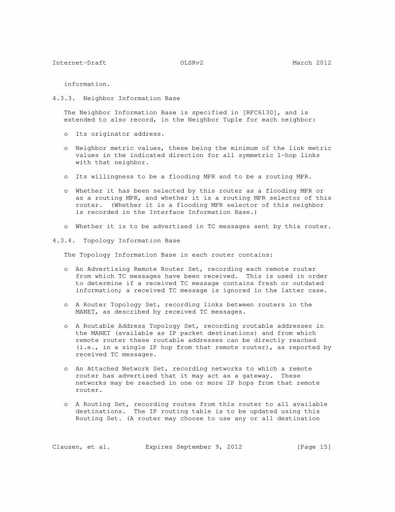
Internet-Draft OLSRv2 March 2012
information.
4.3.3. Neighbor Information Base
The Neighbor Information Base is specified in [RFC6130], and is extended to also record, in the Neighbor Tuple for each neighbor:
o Its originator address.
o Neighbor metric values, these being the minimum of the link metric values in the indicated direction for all symmetric 1-hop links with that neighbor.
o Its willingness to be a flooding MPR and to be a routing MPR.
o Whether it has been selected by this router as a flooding MPR or as a routing MPR, and whether it is a routing MPR selector of this router. (Whether it is a flooding MPR selector of this neighbor is recorded in the Interface Information Base.)
o Whether it is to be advertised in TC messages sent by this router.
4.3.4. Topology Information Base
The Topology Information Base in each router contains:
o An Advertising Remote Router Set, recording each remote router from which TC messages have been received. This is used in order to determine if a received TC message contains fresh or outdated information; a received TC message is ignored in the latter case.
o A Router Topology Set, recording links between routers in the MANET, as described by received TC messages.
o A Routable Address Topology Set, recording routable addresses in the MANET (available as IP packet destinations) and from which remote router these routable addresses can be directly reached (i.e., in a single IP hop from that remote router), as reported by received TC messages.
o An Attached Network Set, recording networks to which a remote router has advertised that it may act as a gateway. These networks may be reached in one or more IP hops from that remote router.
o A Routing Set, recording routes from this router to all available destinations. The IP routing table is to be updated using this Routing Set. (A router may choose to use any or all destination
Clausen, et al. Expires September 9, 2012 [Page 15]

Internet-Draft OLSRv2 March 2012
network addresses in the Routing Set to update the IP routing table, this selection is outside the scope of this specification.)
The purpose of the Topology Information Base is to record information used, in addition to that in the Local Information Base, the Interface Information Bases and the Neighbor Information Base, to construct the Routing Set (which is also included in the Topology Information Base).
This specification describes the calculation of the Routing Set based on a Topology Graph constructed in two phases. First, a "backbone" graph representing the routers in the MANET, and the connectivity between them, is constructed from the Local Information Base, the Neighbor Information Base and the Router Topology Set. Second, this graph is "decorated" with additional destination network addresses using the Local Information Base, the Routable Address Topology Set and the Attached Network Set.
The Topology Graph does not need to be recorded in the Topology Information Base, it can either be constructed as required when the Routing Set is to be changed, or need not be explicitly constructed (as illustrated in Appendix B). An implementation may however construct and retain the Topology Graph if preferred.
4.3.5. Received Message Information Base
The Received Message Information Base in each router contains:
o A Received Set for each OLSRv2 interface, describing TC messages received by this router on that OLSRv2 interface.
o A Processed Set, describing TC messages processed by this router.
o A Forwarded Set, describing TC messages forwarded by this router.
The Received Message Information Base serves the MPR flooding mechanism by ensuring that received messages are forwarded at most once by a router, and also ensures that received messages are processed exactly once by a router. The Received Message Information Base may also record information about other message types that use the MPR flooding mechanism.
4.4. Signaling Overview
This protocol generates and processes HELLO messages according to [RFC6130]. HELLO messages transmitted on OLSRv2 interfaces are extended according to Section 15 of this specification to include an originator address, link metrics, and MPR selection information.
Clausen, et al. Expires September 9, 2012 [Page 16]

Internet-Draft OLSRv2 March 2012
This specification defines a single message type, the TC message. TC messages are sent by their originating router proactively, at a regular interval, on all OLSRv2 interfaces. This interval may be fixed, or may be dynamic, for example it may be backed off due to congestion or network stability. TC messages may also be sent as a response to a change in the router itself, or its advertised symmetric 1-hop neighborhood, for example on first being selected as a routing MPR.
Because TC messages are sent periodically, this protocol is tolerant of unreliable transmissions of TC messages. Message losses may occur more frequently in wireless networks due to collisions or other transmission problems. This protocol may use "jitter", randomized adjustments to message transmission times, to reduce the incidence of collisions, as specified in [RFC5148].
This protocol is tolerant of out of sequence delivery of TC messages due to in transit message reordering. Each router maintains an Advertised Neighbor Sequence Number (ANSN) that is incremented when its recorded neighbor information that is to be included in its TC messages changes. This ANSN is included in the router’s TC messages. The recipient of a TC message can use this included ANSN to identify which of the information it has received is most recent, even if messages have been reordered while in transit. Only the most recent information received is used, older information received later is discarded.
TC messages may be "complete" or "incomplete". A complete TC message advertises all of the originating router’s routing MPR selectors, it may also advertise other symmetric 1-hop neighbors. Complete TC messages are generated periodically (and also, optionally, in response to symmetric 1-hop neighborhood changes). Incomplete TC messages may be used to report additions to advertised information, without repeating unchanged information.
TC messages, and HELLO messages as extended by this specification, define (by inclusion, or by deduction when having a single address) an originator address for the router that created the message. A TC message reports both the originator addresses and routable addresses of its advertised neighbors, distinguishing the two using an Address Block TLV (an address may be both routable and an originator address). TC messages also report the originator’s locally attached networks.
TC messages are MPR flooded throughout the MANET. A router retransmits a TC message received on an OLSRv2 interface if and only if the message did not originate at this router and has not been previously forwarded by this router, this is the first time the
Clausen, et al. Expires September 9, 2012 [Page 17]

Internet-Draft OLSRv2 March 2012
message has been received on this OLSRv2 interface, and the message is received from (i.e., originated from or was last relayed by) one of this router’s flooding MPR selectors.
Some TC messages may be MPR flooded over only part of the network, e.g., allowing a router to ensure that nearer routers are kept more up to date than distant routers, such as is used in Fisheye State Routing [FSR] and Fuzzy Sighted Link State routing [FSLS]. This is enabled using [RFC5497].
TC messages include outgoing neighbor metrics that will be used in the selection of routes.
4.5. Link Metrics
OLSRv1 [RFC3626] created minimum hop routes to destinations. However in many, if not most, circumstances, better routes (in terms of quality of service for end users) can be created by use of link metrics.
OLSRv2, as defined in this specification, allows links to have a metric (also known as a cost). Link metrics as defined in OLSRv2 are additive, and the routes that are to be created are minimum length routes, where the length of a route is defined as the sum of the metrics of the links in that route.
Link metrics are defined to be directional; the link metric from one router to another may be different from that on the reverse link. The link metric is assessed at the receiver, as on a (typically) wireless link, that is the better informed as to link information. Both incoming and outgoing link information is used by OLSRv2, the distinctions in this specification must be clearly followed.
This specification also defines both incoming and outgoing neighbor metrics for each symmetric 1-hop neighbor, these being the minimum value of the link metrics in the same direction for all symmetric links with that neighbor. Note that this means that all neighbor metric values are link metric values and that specification of, for example, link metric value encoding also includes encoding of neighbor metric values.
This specification does not define the nature of the link metric. However, this specification allows, through use of the type extension of a defined Address Block TLV, for link metrics with specific meanings to be defined and either allocated by IANA or privately used. Each HELLO or TC message carrying link (or neighbor) metrics thus indicates which link metric information it is carrying, allowing routers to determine if they can interoperate. If link metrics
Clausen, et al. Expires September 9, 2012 [Page 18]

Internet-Draft OLSRv2 March 2012
require additional signaling to determine their values, whether in HELLO messages or otherwise, then this is permitted but is outside the scope of this specification.
Users are advised that they should carefully consider how to use link metrics. In particular they should not simply default to use of all links with equal metrics (i.e., hop count) for routing without careful consideration of whether that is advisable or not.
4.6. Routing Set Use
The purpose of the Routing Set is to determine and record routes (local interface network address and next hop interface network address) to all possible routable addresses advertised by this protocol, as well as of all destinations that are local, i.e., within one hop, to the router (whether using routable addresses or not). Only symmetric links are used in such routes.
It is intended that the Routing Set can be used for IP packet routing, by using its contents to update the IP routing table. That update, and whether any Routing Tuples are not used in the IP routing table, is outside the scope of this specification.
The signaling in this specification has been designed so that a "backbone" Topology Graph of routers, each identified by its originator address, with at most one direct connection between any pair of routers, can be constructed (from the Neighbor Set and the Router Topology Set) using a suitable minimum path length algorithm. This Topology Graph can then have other network addresses (routable, or of symmetric 1-hop neighbors) added to it (using the Interface Information Bases, the Routable Address Topology Set and the Attached Network Set).
5. Protocol Parameters and Constants
The parameters and constants used in this specification are those defined in [RFC6130] plus those defined in this section. The separation in [RFC6130] into interface parameters, router parameters and constants is also used in this specification.
As for the parameters in [RFC6130], parameters defined in this specification MAY be changed dynamically by a router, and need not be the same on different routers, even in the same MANET, or, for interface parameters, on different interfaces of the same router.
Clausen, et al. Expires September 9, 2012 [Page 19]

Internet-Draft OLSRv2 March 2012
5.1. Protocol and Port Numbers
This protocol specifies TC messages, which are included in packets as defined by [RFC5444]. These packets may be sent either using the "manet" protocol number or the "manet" UDP well-known port number, as specified in [RFC5498].
TC messages and HELLO messages [RFC6130] MUST, in a given MANET, both be using the same of either of IP or UDP, in order that it is possible to combine messages of both protocols into the same [RFC5444] packet for transmission.
5.2. Multicast Address
This protocol specifies TC messages, which are included in packets as defined by [RFC5444]. These packets MAY be transmitted using the link local multicast address "LL-MANET-Routers", as specified in [RFC5498].
5.3. Interface Parameters
A single additional interface parameter is specified for OLSRv2 interfaces only.
5.3.1. Received Message Validity Time
The following parameter manages the validity time of recorded received message information:
RX_HOLD_TIME: The period after receipt of a message by the appropriate OLSRv2 interface of this router for which that information is recorded, in order that the message is recognized as having been previously received on this OLSRv2 interface.
The following constraints apply to this parameter:
o RX_HOLD_TIME > 0
o RX_HOLD_TIME SHOULD be greater than the maximum difference in time that a message may take to traverse the MANET, taking into account any message forwarding jitter as well as propagation, queuing, and processing delays.
Clausen, et al. Expires September 9, 2012 [Page 20]

Internet-Draft OLSRv2 March 2012
5.4. Router Parameters
5.4.1. Local History Times
The following router parameter manages the time for which local information is retained:
O_HOLD_TIME: The time for which a recently used and replaced originator address is used to recognize the router’s own messages.
The following constraint apply to this parameter:
o O_HOLD_TIME > 0
5.4.2. Link Metric Parameters
All routes found using this specification use a single link metric type that is specified by the router parameter LINK_METRIC_TYPE, which may take any value from 0 to 255, inclusive.
5.4.3. Message Intervals
The following parameters regulate TC message transmissions by a router. TC messages are usually sent periodically, but MAY also be sent in response to changes in the router’s Neighbor Set and/or Local Attached Network Set. In a highly dynamic network, and with a larger value of the parameter TC_INTERVAL and a smaller value of the parameter TC_MIN_INTERVAL, TC messages may be transmitted more often in response to changes than periodically. However, because a router has no knowledge of, for example, routers remote to it (i.e., beyond two hops away) joining the network, TC messages MUST NOT be sent purely responsively.
TC_INTERVAL: The maximum time between the transmission of two successive TC messages by this router. When no TC messages are sent in response to local network changes (by design, or because the local network is not changing) then TC messages MUST be sent at a regular interval TC_INTERVAL, possibly modified by jitter as specified in [RFC5148].
TC_MIN_INTERVAL: The minimum interval between transmission of two successive TC messages by this router. (This minimum interval MAY be modified by jitter, as specified in [RFC5148].)
The following constraints apply to these parameters:
Clausen, et al. Expires September 9, 2012 [Page 21]

Internet-Draft OLSRv2 March 2012
o TC_INTERVAL > 0
o TC_MIN_INTERVAL >= 0
o TC_INTERVAL >= TC_MIN_INTERVAL
o If TLVs with Type = INTERVAL_TIME, as defined in [RFC5497], are included in TC messages, then TC_INTERVAL MUST be representable as described in [RFC5497].
5.4.4. Advertised Information Validity Times
The following parameters manage the validity time of information advertised in TC messages:
T_HOLD_TIME: Used as the minimum value in the TLV with Type = VALIDITY_TIME included in all TC messages sent by this router. If a single value of parameter TC_HOP_LIMIT (see Section 5.4.7) is used then this will be the only value in that TLV.
A_HOLD_TIME: The period during which TC messages are sent after they no longer have any advertised information to report, but are sent in order to accelerate outdated information removal by other routers.
The following constraints apply to these parameters:
o T_HOLD_TIME > 0
o A_HOLD_TIME >= 0
o T_HOLD_TIME >= TC_INTERVAL
o If TC messages can be lost, then both T_HOLD_TIME and A_HOLD_TIME SHOULD be significantly greater than TC_INTERVAL; a value >= 3 x TC_INTERVAL is RECOMMENDED.
o T_HOLD_TIME MUST be representable as described in [RFC5497].
5.4.5. Processing and Forwarding Validity Times
The following parameters manage the processing and forwarding validity time of recorded message information:
Clausen, et al. Expires September 9, 2012 [Page 22]

Internet-Draft OLSRv2 March 2012
P_HOLD_TIME: The period after receipt of a message that is processed by this router for which that information is recorded, in order that the message is not processed again if received again.
F_HOLD_TIME: The period after receipt of a message that is forwarded by this router for which that information is recorded, in order that the message is not forwarded again if received again.
The following constraints apply to these parameters:
o P_HOLD_TIME > 0
o F_HOLD_TIME > 0
o Both of these parameters SHOULD be greater than the maximum difference in time that a message may take to traverse the MANET, taking into account any message forwarding jitter as well as propagation, queuing, and processing delays.
5.4.6. Jitter
If jitter, as defined in [RFC5148], is used then the governing jitter parameters are as follows:
TP_MAXJITTER: Represents the value of MAXJITTER used in [RFC5148] for periodically generated TC messages sent by this router.
TT_MAXJITTER: Represents the value of MAXJITTER used in [RFC5148] for externally triggered TC messages sent by this router.
F_MAXJITTER: Represents the default value of MAXJITTER used in [RFC5148] for messages forwarded by this router. However, before using F_MAXJITTER a router MAY attempt to deduce a more appropriate value of MAXJITTER, for example based on any TLVs with Type = INTERVAL_TIME or Type = VALIDITY_TIME contained in the message to be forwarded.
For constraints on these parameters see [RFC5148].
5.4.7. Hop Limit
The parameter TC_HOP_LIMIT is the hop limit set in each TC message. TC_HOP_LIMIT MAY be a single fixed value, or MAY be different in TC
Clausen, et al. Expires September 9, 2012 [Page 23]

Internet-Draft OLSRv2 March 2012
messages sent by the same router. However each other router, at any hop count distance, MUST see a regular pattern of TC messages in order that meaningful values of TLVs with Type = INTERVAL_TIME and Type = VALIDITY_TIME at each hop count distance can be included as defined in [RFC5497]. Thus the pattern of TC_HOP_LIMIT MUST be defined to have this property. For example the repeating pattern (255 4 4) satisfies this property (having period TC_INTERVAL at hop counts up to 4, inclusive, and 3 x TC_INTERVAL at hop counts greater than 4), but the repeating pattern (255 255 4 4) does not satisfy this property because at hop counts greater than 4, message intervals are alternately TC_INTERVAL and 3 x TC_INTERVAL.
The following constraints apply to this parameter:
o The maximum value of TC_HOP_LIMIT >= the network diameter in hops, a value of 255 is RECOMMENDED. Note that if using a pattern of different values of TC_HOP_LIMIT as described above, then only the maximum value in the pattern is so constrained.
o All values of TC_HOP_LIMIT >= 2.
5.4.8. Willingness
Each router has two willingness parameters: WILL_FLOODING and WILL_ROUTING, each of which MUST be in the range WILL_NEVER to WILL_ALWAYS, inclusive.
WILL_FLOODING represents the router’s willingness to be selected as a flooding MPR and hence to participate in MPR flooding, in particular of TC messages.
WILL_ROUTING represents the router’s willingness to be selected as a routing MPR and hence to be an intermediate router on routes.
In either case, the higher the value, the greater the router’s willingness to be a flooding or routing MPR, respectively. If a router has a willingness value of WILL_NEVER (the lowest possible value) it does not perform the corresponding task. A MANET using this protocol with too many routers having either willingness value equal to WILL_NEVER will not function; it MUST be ensured, by administrative or other means, that this does not happen.
If a router has a willingness value equal to WILL_ALWAYS (the highest possible value) then it will always be selected as a flooding or routing MPR, respectively, by all symmetric 1-hop neighbors.
In a MANET in which all routers have WILL_FLOODING = WILL_ALWAYS, flooding reduction will effectively be disabled, and flooding will
Clausen, et al. Expires September 9, 2012 [Page 24]

Internet-Draft OLSRv2 March 2012
perform as blind flooding.
In a MANET in which all routers have WILL_ROUTING = WILL_ALWAYS, topology reduction will effectively be disabled, and all routers will advertise all of their links in TC messages.
A router that has WILL_ROUTING = WILL_NEVER will not act as an intermediate router in the MANET. Such a router can, act as a source, destination or gateway to another routing domain.
Different routers MAY have different values for WILL_FLOODING and/or WILL_ROUTING.
The following constraints apply to these parameters:
o WILL_FLOODING >= WILL_NEVER
o WILL_FLOODING <= WILL_ALWAYS
o WILL_ROUTING >= WILL_NEVER
o WILL_ROUTING <= WILL_ALWAYS
5.5. Parameter Change Constraints
If protocol parameters are changed dynamically, then the constraints in this section apply.
RX_HOLD_TIME
* If RX_HOLD_TIME for an OLSRv2 interface changes, then the expiry time for all Received Tuples for that OLSRv2 interface MAY be changed.
O_HOLD_TIME
* If O_HOLD_TIME changes, then the expiry time for all Originator Tuples MAY be changed.
TC_INTERVAL
* If TC_INTERVAL increases, then the next TC message generated by this router MUST be generated according to the previous, shorter, TC_INTERVAL. Additional subsequent TC messages MAY be generated according to the previous, shorter, TC_INTERVAL.
* If TC_INTERVAL decreases, then the following TC messages from this router MUST be generated according to the current,
Clausen, et al. Expires September 9, 2012 [Page 25]

Internet-Draft OLSRv2 March 2012
shorter, TC_INTERVAL.
P_HOLD_TIME
* If P_HOLD_TIME changes, then the expiry time for all Processed Tuples MAY be changed.
F_HOLD_TIME
* If F_HOLD_TIME changes, then the expiry time for all Forwarded Tuples MAY be changed.
TP_MAXJITTER
* If TP_MAXJITTER changes, then the periodic TC message schedule on this router MAY be changed immediately.
TT_MAXJITTER
* If TT_MAXJITTER changes, then externally triggered TC messages on this router MAY be rescheduled.
F_MAXJITTER
* If F_MAXJITTER changes, then TC messages waiting to be forwarded with a delay based on this parameter MAY be rescheduled.
TC_HOP_LIMIT
* If TC_HOP_LIMIT changes, and the router uses multiple values after the change, then message intervals and validity times included in TC messages MUST be respected. The simplest way to do this is to start any new repeating pattern of TC_HOP_LIMIT values with its largest value.
LINK_METRIC_TYPE
* If LINK_METRIC_TYPE changes, then all link metric information recorded by the router is invalid. The router MUST take the following actions, and all consequent actions described in Section 17 and [RFC6130].
+ For each Link Tuple in any Link Set for an OLSRv2 interface, either update L_in_metric (the value MAXIMUM_METRIC MAY be used) or remove the Link Tuple from the Link Set.
Clausen, et al. Expires September 9, 2012 [Page 26]

Internet-Draft OLSRv2 March 2012
+ For each Link Tuple that is not removed, set:
- L_out_metric := UNKNOWN_METRIC;
- L_SYM_time := expired;
- L_MPR_selector := false.
+ Remove all Router Topology Tuples, Routable Address Topology Tuples, Attached Network Tuples and Routing Tuples from their respective Protocol Sets in the Topology Information Base.
5.6. Constants
5.6.1. Link Metric Constants
The constant minimum and maximum link metric values are defined by:
o MINIMUM_METRIC := 1
o MAXIMUM_METRIC := 16776960
The symbolic value UNKNOWN_METRIC is defined in Section 6.1.
5.6.2. Willingness Constants
The constant minimum, RECOMMENDED default, and maximum, willingness values are defined by:
o WILL_NEVER := 0
o WILL_DEFAULT := 7
o WILL_ALWAYS := 15
6. Link Metric Values
A router records a link metric value for each direction of a link of which it has knowledge. These link metric values are used to create metrics for routes by the addition of link metric values.
6.1. Link Metric Representation
Link metrics are reported in messages using a compressed representation that occupies 12 bits, a 4 bit field and an 8 bit field. The compressed representation represents positive integer values with a minimum value of 1 and a maximum value that is slightly
Clausen, et al. Expires September 9, 2012 [Page 27]

Internet-Draft OLSRv2 March 2012
smaller than the maximum 24 bit value. Only those values that have exact representation in the compressed form are used. Route metrics are the summation of no more than 255 link metric values, and can therefore be represented using no more than 32 bits.
Link and route metrics used in the Information Bases defined in this specification refer to the uncompressed values, and arithmetic involving them does likewise, and assumes full precision in the result. (How an implementation records the values is not part of this specification, as long as it behaves as if recording uncompressed values. An implementation can, for example, use 32 bit values for all link and route metrics.)
In some cases a link metric value may be unknown. This is indicated in this specification by the symbolic value UNKNOWN_METRIC. An implementation may use any representation of UNKNOWN_METRIC as it is never included in messages, or used in any computation. (Possible representations are zero, or any value greater than the maximum representable metric value.)
6.2. Link Metric Compressed Form
The 12-bit compressed form of a link metric uses a modified form of a representation with an 8-bit mantissa (denoted b) and a 4-bit exponent (denoted a). Note that if represented as the 12 bit value 256a+b then the ordering of those 12 bit values is identical to the ordering of the represented values.
The value so represented is (257+b)2^a - 256, where ^ denotes exponentiation. This has a minimum value (when a = 0 and b = 0) of MINIMUM_METRIC = 1 and a maximum value (when a = 15 and b = 255) of MAXIMUM_METRIC = 2^24 - 256.
An algorithm for computing a and b for the smallest representable value not less than a link metric value v such that MINIMUM_METRIC <= v <= MAXIMUM_METRIC is:
1. Find the smallest integer a such that v + 256 <= 2^(a + 9).
2. Set b := (v - 256(2^a - 1)) / (2^a) - 1, rounded up to the nearest integer.
7. Local Information Base
The Local Information Base, as defined for each router in [RFC6130], is extended by this protocol by:
Clausen, et al. Expires September 9, 2012 [Page 28]

Internet-Draft OLSRv2 March 2012
o Recording the router’s originator address. The originator address MUST be unique to this router. It MUST NOT be used by any other router as an originator address. It MAY be included in any network address in any I_local_iface_addr_list of this router, it MUST NOT be included in any network address in any I_local_iface_addr_list of any other router. It MAY be included in, but MUST NOT be equal to, the AL_net_addr in any Local Attached Network Tuple in this or any other router.
o The addition of an Originator Set, defined in Section 7.1, and a Local Attached Network Set, defined in Section 7.2.
All routable addresses of the router for which it is to accept IP packets as destination MUST be included in the Local Interface Set or the Local Attached Network Set.
7.1. Originator Set
A router’s Originator Set records addresses that were recently used as originator addresses by this router. If a router’s originator address is immutable then the Originator Set is always empty and MAY be omitted. It consists of Originator Tuples:
(O_orig_addr, O_time)
where:
O_orig_addr is a recently used originator address; note that this does not include a prefix length;
O_time specifies the time at which this Tuple expires and MUST be removed.
7.2. Local Attached Network Set
A router’s Local Attached Network Set records its local non-OLSRv2 interfaces via which it can act as gateways to other networks. The Local Attached Network Set is not modified by this protocol. This protocol MAY respond to changes to the Local Attached Network Set, which MUST reflect corresponding changes in the router’s status. It consists of Local Attached Network Tuples:
(AL_net_addr, AL_dist, AL_metric)
where:
AL_net_addr is the network address of an attached network which can be reached via this router. This SHOULD be a routable
Clausen, et al. Expires September 9, 2012 [Page 29]

Internet-Draft OLSRv2 March 2012
address. It is constrained as described below.
AL_dist is the number of hops to the network with network address AL_net_addr from this router.
AL_metric is the metric of the link to the attached network with address AL_net_addr from this router;
Attached networks local to this router only (i.e., not reachable except via this router) SHOULD be treated as local non-MANET interfaces, and added to the Local Interface Set, as specified in [RFC6130], rather than be added to the Local Attached Network Set.
Because an attached network is not specific to the router, and may be outside the MANET, an attached network MAY also be attached to other routers. Routing to an AL_net_addr will use maximum prefix length matching; consequently an AL_net_addr MAY include, but MUST NOT equal or be included in, any network address which is of any interface of any router (i.e., is included in any I_local_iface_addr_list) or equal any router’s originator address.
It is not the responsibility of this protocol to maintain routes from this router to networks recorded in the Local Attached Network Set.
Local Attached Neighbor Tuples are removed from the Local Attached Network Set only when the router’s local attached network configuration changes, i.e., they are not subject to timer-based expiration or changes due to received messages.
8. Interface Information Base
An Interface Information Base, as defined in [RFC6130], is maintained for each MANET interface. The Link Set and 2-Hop Set in the Interface Information Base for an OLSRv2 interface are modified by this protocol. In some cases it may be convenient to consider these Sets as also containing these additional elements for other MANET interfaces, taking the indicated values on creation, but never being updated.
8.1. Link Set
The Link Set is modified by adding these additional elements to each Link Tuple:
L_in_metric is the metric of the link from the OLSRv2 interface with addresses L_neighbor_iface_addr_list to this OLSRv2 interface;
Clausen, et al. Expires September 9, 2012 [Page 30]

Internet-Draft OLSRv2 March 2012
L_out_metric is the metric of the link to the OLSRv2 interface with addresses L_neighbor_iface_addr_list from this OLSRv2 interface;
L_mpr_selector is a boolean flag, describing if this neighbor has selected this router as a flooding MPR, i.e., is a flooding MPR selector of this router.
L_in_metric will be specified by a process that is external to this specification. Any Link Tuple with L_status = HEARD or L_status = SYMMETRIC MUST have a specified value of L_in_metric if it is to be used by this protocol.
A Link Tuple created (but not updated) by [RFC6130] MUST set:
o L_in_metric := UNKNOWN_METRIC;
o L_out_metric := UNKNOWN_METRIC;
o L_mpr_selector := false.
8.2. 2-Hop Set
The 2-Hop Set is modified by adding these additional elements to each 2-Hop Tuple:
N2_in_metric is the neighbor metric from the router with address N2_2hop_iface_addr to the router with OLSRv2 interface addresses N2_neighbor_iface_addr_list;
N2_out_metric is the neighbor metric to the router with address N2_2hop_iface_addr from the router with OLSRv2 interface addresses N2_neighbor_iface_addr_list.
A 2-Hop Tuple created (but not updated) by [RFC6130] MUST set:
o N2_in_metric := UNKNOWN_METRIC;
o N2_out_metric := UNKNOWN_METRIC.
9. Neighbor Information Base
A Neighbor Information Base, as defined in [RFC6130], is maintained for each router. It is modified by this protocol by adding these additional elements to each Neighbor Tuple in the Neighbor Set. In some cases it may be convenient to consider these Sets as also containing these additional elements for other MANET interfaces, taking the indicated values on creation, but never being updated.
Clausen, et al. Expires September 9, 2012 [Page 31]

Internet-Draft OLSRv2 March 2012
N_orig_addr is the neighbor’s originator address, which may be unknown. Note that this originator address does not include a prefix length;
N_in_metric is the neighbor metric of any link from this neighbor to an OLSRv2 interface of this router, i.e., the minimum of all corresponding L_in_metric with L_status = SYMMETRIC and L_in_metric != UNKNOWN_METRIC, UNKNOWN_METRIC if there are no such Link Tuples;
N_out_metric is the neighbor metric of any link from an OLSRv2 interface of this router to this neighbor, i.e., the minimum of all corresponding L_out_metric with L_status = SYMMETRIC and L_out_metric != UNKNOWN_METRIC, UNKNOWN_METRIC if there are no such Link Tuples;
N_will_flooding is the neighbor’s willingness to be selected as a flooding MPR, in the range from WILL_NEVER to WILL_ALWAYS, both inclusive, taking the value WILL_NEVER if no OLSRv2 specific information is received from this neighbor;
N_will_routing is the neighbor’s willingness to be selected as a routing MPR, in the range from WILL_NEVER to WILL_ALWAYS, both inclusive, taking the value WILL_NEVER if no OLSRv2 specific information is received from this neighbor;
N_flooding_mpr is a boolean flag, describing if this neighbor is selected as a flooding MPR by this router;
N_routing_mpr is a boolean flag, describing if this neighbor is selected as a routing MPR by this router;
N_mpr_selector is a boolean flag, describing if this neighbor has selected this router as a routing MPR, i.e., is a routing MPR selector of this router.
N_advertised is a boolean flag, describing if this router has elected to advertise a link to this neighbor in its TC messages.
A Neighbor Tuple created (but not updated) by [RFC6130] MUST set:
o N_orig_addr := unknown;
o N_in_metric := UNKNOWN_METRIC;
o N_out_metric := UNKNOWN_METRIC;
Clausen, et al. Expires September 9, 2012 [Page 32]

Internet-Draft OLSRv2 March 2012
o N_will_flooding := WILL_NEVER;
o N_will_routing := WILL_NEVER;
o N_routing_mpr := false;
o N_flooding_mpr := false;
o N_mpr_selector := false;
o N_advertised := false.
The Neighbor Information Base also includes a variable, the Advertised Neighbor Sequence Number (ANSN), whose value is included in TC messages to indicate the freshness of the information transmitted. The ANSN is incremented whenever advertised information (the originator and routable addresses included in Neighbor Tuples with N_advertised = true, and local attached networks recorded in the Local Attached Network Set in the Local Information Base) changes, including addition or removal of such information.
10. Topology Information Base
The Topology Information Base, defined for each router by this specification, stores information received in TC messages, in the Advertising Remote Router Set, the Router Topology Set, the Routable Address Topology Set and the Attached Network Set.
Additionally, a Routing Set is maintained, derived from the information recorded in the Local Information Base, the Interface Information Bases, the Neighbor Information Base and the rest of the Topology Information Base.
10.1. Advertising Remote Router Set
A router’s Advertising Remote Router Set records information describing each remote router in the network that transmits TC messages, allowing outdated TC messages to be recognized and discarded. It consists of Advertising Remote Router Tuples:
(AR_orig_addr, AR_seq_number, AR_time)
where:
AR_orig_addr is the originator address of a received TC message, note that this does not include a prefix length;
Clausen, et al. Expires September 9, 2012 [Page 33]

Internet-Draft OLSRv2 March 2012
AR_seq_number is the greatest ANSN in any TC message received which originated from the router with originator address AR_orig_addr (i.e., which contributed to the information contained in this Tuple);
AR_time is the time at which this Tuple expires and MUST be removed.
10.2. Router Topology Set
A router’s Topology Set records topology information about the links between routers in the MANET. It consists of Router Topology Tuples:
(TR_from_orig_addr, TR_to_orig_addr, TR_seq_number, TR_metric, TR_time)
where:
TR_from_orig_addr is the originator address of a router which can reach the router with originator address TR_to_orig_addr in one hop, note that this does not include a prefix length;
TR_to_orig_addr is the originator address of a router which can be reached by the router with originator address TR_to_orig_addr in one hop, note that this does not include a prefix length;
TR_seq_number is the greatest ANSN in any TC message received which originated from the router with originator address TR_from_orig_addr (i.e., which contributed to the information contained in this Tuple);
TR_metric is the neighbor metric from the router with originator address TR_from_orig_addr to the router with originator address TR_to_orig_addr;
TR_time specifies the time at which this Tuple expires and MUST be removed.
10.3. Routable Address Topology Set
A router’s Routable Address Topology Set records topology information about the routable addresses within the MANET, and via which routers they may be reached. It consists of Routable Address Topology Tuples:
(TA_from_orig_addr, TA_dest_addr, TA_seq_number, TA_metric, TA_time)
Clausen, et al. Expires September 9, 2012 [Page 34]

Internet-Draft OLSRv2 March 2012
where:
TA_from_orig_addr is the originator address of a router which can reach the router with routable address TA_dest_addr in one hop, note that this does not include a prefix length;
TA_dest_addr is a routable address of a router which can be reached by the router with originator address TA_from_orig_addr in one hop;
TA_seq_number is the greatest ANSN in any TC message received which originated from the router with originator address TA_from_orig_addr (i.e., which contributed to the information contained in this Tuple);
TA_metric is the neighbor metric from the router with originator address TA_from_orig_addr to the router with OLSRv2 interface address TA_dest_addr;
TA_time specifies the time at which this Tuple expires and MUST be removed.
10.4. Attached Network Set
A router’s Attached Network Set records information about networks (which may be outside the MANET) attached to other routers and their routable addresses. It consists of Attached Network Tuples:
(AN_orig_addr, AN_net_addr, AN_seq_number, AN_dist, AN_metric, AN_time)
where:
AN_orig_addr is the originator address of a router which can act as gateway to the network with network address AN_net_addr, note that this does not include a prefix length;
AN_net_addr is the network address of an attached network, which may be reached via the router with originator address AN_orig_addr;
AN_seq_number is the greatest ANSN in any TC message received which originated from the router with originator address AN_orig_addr (i.e., which contributed to the information contained in this Tuple);
AN_dist is the number of hops to the network with network address AN_net_addr from the router with originator address AN_orig_addr;
Clausen, et al. Expires September 9, 2012 [Page 35]
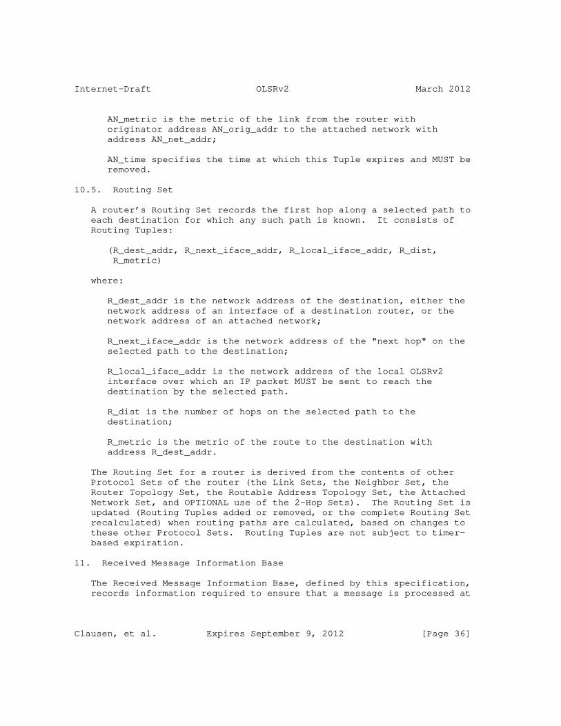
Internet-Draft OLSRv2 March 2012
AN_metric is the metric of the link from the router with originator address AN_orig_addr to the attached network with address AN_net_addr;
AN_time specifies the time at which this Tuple expires and MUST be removed.
10.5. Routing Set
A router’s Routing Set records the first hop along a selected path to each destination for which any such path is known. It consists of Routing Tuples:
(R_dest_addr, R_next_iface_addr, R_local_iface_addr, R_dist, R_metric)
where:
R_dest_addr is the network address of the destination, either the network address of an interface of a destination router, or the network address of an attached network;
R_next_iface_addr is the network address of the "next hop" on the selected path to the destination;
R_local_iface_addr is the network address of the local OLSRv2 interface over which an IP packet MUST be sent to reach the destination by the selected path.
R_dist is the number of hops on the selected path to the destination;
R_metric is the metric of the route to the destination with address R_dest_addr.
The Routing Set for a router is derived from the contents of other Protocol Sets of the router (the Link Sets, the Neighbor Set, the Router Topology Set, the Routable Address Topology Set, the Attached Network Set, and OPTIONAL use of the 2-Hop Sets). The Routing Set is updated (Routing Tuples added or removed, or the complete Routing Set recalculated) when routing paths are calculated, based on changes to these other Protocol Sets. Routing Tuples are not subject to timer- based expiration.
11. Received Message Information Base
The Received Message Information Base, defined by this specification, records information required to ensure that a message is processed at
Clausen, et al. Expires September 9, 2012 [Page 36]

Internet-Draft OLSRv2 March 2012
most once and is forwarded at most once per OLSRv2 interface of a router, using MPR flooding. Messages are recorded using their "signature", consisting of their type, originator address, and message sequence number.
11.1. Received Set
A router has a Received Set per OLSRv2 interface. Each Received Set records the signatures of messages which have been received over that OLSRv2 interface. Each consists of Received Tuples:
(RX_type, RX_orig_addr, RX_seq_number, RX_time)
where:
RX_type is the received Message Type;
RX_orig_addr is the originator address of the received message, note that this does not include a prefix length;
RX_seq_number is the message sequence number of the received message;
RX_time specifies the time at which this Tuple expires and MUST be removed.
11.2. Processed Set
A router has a single Processed Set which records signatures of messages which have been processed by the router. It consists of Processed Tuples:
(P_type, P_orig_addr, P_seq_number, P_time)
where:
P_type is the processed Message Type;
P_orig_addr is the originator address of the processed message, note that this does not include a prefix length;
P_seq_number is the message sequence number of the processed message;
P_time specifies the time at which this Tuple expires and MUST be removed.
Clausen, et al. Expires September 9, 2012 [Page 37]

Internet-Draft OLSRv2 March 2012
11.3. Forwarded Set
A router has a single Forwarded Set which records signatures of messages which have been forwarded by the router. It consists of Forwarded Tuples:
(F_type, F_orig_addr, F_seq_number, F_time)
where:
F_type is the forwarded Message Type;
F_orig_addr is the originator address of the forwarded message, note that this does not include a prefix length;
F_seq_number is the message sequence number of the forwarded message;
F_time specifies the time at which this Tuple expires and MUST be removed.
12. Information Base Properties
As part of this specification, in a number of cases there is a natural correspondence from a Protocol Tuple in one Protocol Set to a single Protocol Tuple in another Protocol Set, in the same or another Information Base. The latter Protocol Tuple is referred to as "corresponding" to the former Protocol Tuple.
Specific examples of corresponding Protocol Tuples include:
o There is a Local Interface Tuple corresponding to each Link Tuple, where the Link Tuple is in the Link Set for a MANET interface, and the Local Interface Tuple represents that MANET interface.
o There is a Neighbor Tuple corresponding to each Link Tuple which has L_HEARD_time not expired, such that N_neighbor_addr_list contains L_neighbor_iface_addr_list.
o There is a Link Tuple (in the Link Set in the same Interface Information Base) corresponding to each 2-Hop Tuple such that L_neighbor_iface_addr_list = N2_neighbor_iface_addr_list.
o There is a Neighbor Tuple corresponding to each 2-Hop Tuple, such that N_neighbor_addr_list contains N2_neighbor_iface_addr_list. (This is the Neighbor Tuple corresponding to the Link Tuple corresponding to the 2-Hop Tuple.)
Clausen, et al. Expires September 9, 2012 [Page 38]

Internet-Draft OLSRv2 March 2012
o There is an Advertising Remote Router Tuple corresponding to each Router Topology Tuple such that AR_orig_addr = TR_from_orig_addr.
o There is an Advertising Remote Router Tuple corresponding to each Routable Address Topology Tuple such that AR_orig_addr = TA_from_orig_addr.
o There is an Advertising Remote Router Tuple corresponding to each Attached Network Tuple such that AR_orig_addr = AN_orig_addr.
o There is a Neighbor Tuple corresponding to each Routing Tuple such that N_neighbor_addr_list contains R_next_iface_addr.
Addresses or network addresses with the following properties are considered as "fully owned" by a router when processing a received message:
o Equaling its originator address, OR;
o Equaling the O_orig_addr in an Originator Tuple, OR;
o Equaling or being a sub-range of the I_local_iface_addr_list in a Local Interface Tuple, OR;
o Equaling or being a sub-range of the IR_local_iface_addr in a Removed Interface Address Tuple, OR;
o Equaling an AL_net_addr in a Local Attached Network Tuple.
Addresses or network addresses with the following properties are considered as "partially owned" (which may include being fully owned) by a router when processing a received message:
o Overlapping (equaling or containing) its originator address, OR;
o Overlapping (equaling or containing) the O_orig_addr in an Originator Tuple, OR;
o Overlapping the I_local_iface_addr_list in a Local Interface Tuple, OR;
o Overlapping the IR_local_iface_addr in a Removed Interface Address Tuple, OR;
o Equaling or having as a sub-range an AL_net_addr in a Local Attached Network Tuple.
Clausen, et al. Expires September 9, 2012 [Page 39]

Internet-Draft OLSRv2 March 2012
13. Packets and Messages
The packet and message format used by this protocol is defined in [RFC5444]. Except as otherwise noted, options defined in [RFC5444] may be freely used, in particular alternative formats defined by packet, message, Address Block and TLV flags.
This section describes the usage of the packets and messages defined in [RFC5444] by this specification, and the TLVs defined by, and used in, this specification.
13.1. Messages
Routers using this protocol exchange information through messages. The message types used by this protocol are the HELLO message and the TC message. The HELLO message is defined by [RFC6130] and extended by this specification, see Section 15. The TC message is defined by this specification, see Section 16.
13.2. Packets
One or more messages sent by a router at the same time SHOULD be combined into a single packet, subject to any constraints on maximum packet size (such as derived from the MTU over a local single hop) that MAY be imposed. These messages may have originated at the sending router, or have originated at another router and are being forwarded by the sending router. Messages with different originating routers MAY be combined for transmission within the same packet. Messages from other protocols defined using [RFC5444], including but not limited to [RFC6130], MAY be combined for transmission within the same packet. This specification does not define or use any contents of the Packet Header.
Forwarded messages MAY be jittered as described in [RFC5148], including the observation that the forwarding jitter of all messages received in a single packet SHOULD be the same. The value of MAXJITTER used in jittering a forwarded message MAY be based on information in that message (in particular any Message TLVs with Type = INTERVAL_TIME or Type = VALIDITY_TIME) or otherwise SHOULD be with a maximum delay of F_MAXJITTER. A router MAY modify the jitter applied to a message in order to more efficiently combine messages in packets, as long as the maximum jitter is not exceeded.
13.3. TLVs
This specification defines two Message TLVs and four Address Block TLVs.
Clausen, et al. Expires September 9, 2012 [Page 40]
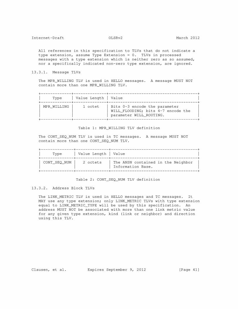
Internet-Draft OLSRv2 March 2012
All references in this specification to TLVs that do not indicate a type extension, assume Type Extension = 0. TLVs in processed messages with a type extension which is neither zero as so assumed, nor a specifically indicated non-zero type extension, are ignored.
13.3.1. Message TLVs
The MPR_WILLING TLV is used in HELLO messages. A message MUST NOT contain more than one MPR_WILLING TLV.
+-------------+--------------+--------------------------------------+ | Type | Value Length | Value | +-------------+--------------+--------------------------------------+ | MPR_WILLING | 1 octet | Bits 0-3 encode the parameter | | | | WILL_FLOODING; bits 4-7 encode the | | | | parameter WILL_ROUTING. | +-------------+--------------+--------------------------------------+
Table 1: MPR_WILLING TLV definition
The CONT_SEQ_NUM TLV is used in TC messages. A message MUST NOT contain more than one CONT_SEQ_NUM TLV.
+--------------+--------------+-------------------------------------+ | Type | Value Length | Value | +--------------+--------------+-------------------------------------+ | CONT_SEQ_NUM | 2 octets | The ANSN contained in the Neighbor | | | | Information Base. | +--------------+--------------+-------------------------------------+
Table 2: CONT_SEQ_NUM TLV definition
13.3.2. Address Block TLVs
The LINK_METRIC TLV is used in HELLO messages and TC messages. It MAY use any type extension; only LINK_METRIC TLVs with type extension equal to LINK_METRIC_TYPE will be used by this specification. An address MUST NOT be associated with more than one link metric value for any given type extension, kind (link or neighbor) and direction using this TLV.
Clausen, et al. Expires September 9, 2012 [Page 41]

Internet-Draft OLSRv2 March 2012
+-------------+--------------+--------------------------------------+ | Type | Value Length | Value | +-------------+--------------+--------------------------------------+ | LINK_METRIC | 2 octets | Bits 0-3 indicates kind(s) and | | | | direction(s), bits 4-7 indicate | | | | exponent (a), bits 8-15 indicate | | | | mantissa (b) | +-------------+--------------+--------------------------------------+
Table 3: LINK_METRIC TLV definition
The exponent and mantissa use the representation defined in Section 6. Each bit of the types and directions sub-field, if set (’1’) indicates that the link metric is of the indicated kind and direction. Any combination of these bits MAY be used.
+-----+-----------------+-----------+ | Bit | Kind | Direction | +-----+-----------------+-----------+ | 0 | Link metric | Incoming | | 1 | Link metric | Outgoing | | 2 | Neighbor metric | Incoming | | 3 | Neighbor metric | Outgoing | +-----+-----------------+-----------+
Table 4: LINK_METRIC TLV types and directions
The MPR TLV is used in HELLO messages, and indicates that an address with which it is associated is of a symmetric 1-hop neighbor that has been selected as an MPR.
+------+--------------+---------------------------------------------+ | Type | Value Length | Value | +------+--------------+---------------------------------------------+ | MPR | 1 octet | FLOODING indicates that the corresponding | | | | address is of a neighbor selected as a | | | | flooding MPR, ROUTING indicates that the | | | | corresponding address is of a neighbor | | | | selected as a routing MPR, FLOOD_ROUTE | | | | indicates both (see Section 24.6). | +------+--------------+---------------------------------------------+
Table 5: MPR TLV definition
The NBR_ADDR_TYPE TLV is used in TC messages.
Clausen, et al. Expires September 9, 2012 [Page 42]

Internet-Draft OLSRv2 March 2012
+---------------+--------------+------------------------------------+ | Type | Value Length | Value | +---------------+--------------+------------------------------------+ | NBR_ADDR_TYPE | 1 octet | ORIGINATOR indicates that the | | | | corresponding address (which MUST | | | | have maximum prefix length) is an | | | | originator address, ROUTABLE | | | | indicates that the corresponding | | | | network address is a routable | | | | address of an interface, | | | | ROUTABLE_ORIG indicates that the | | | | corresponding address is both (see | | | | Section 24.6). | +---------------+--------------+------------------------------------+
Table 6: NBR_ADDR_TYPE TLV definition
If an address is both an originator address and a routable address, then it may be associated with either one Address Block TLV with Type := NBR_ADDR_TYPE and Value := ROUTABLE_ORIG, or with two Address Block TLVs with Type:= NBR_ADDR_TYPE, one with Value := ORIGINATOR and one with Value := ROUTABLE.
The GATEWAY TLV is used in TC messages. An address MUST NOT be associated with more than one hop count value using this TLV.
+---------+--------------+-------------------------------------+ | Type | Value Length | Value | +---------+--------------+-------------------------------------+ | GATEWAY | 1 octet | Number of hops to attached network. | +---------+--------------+-------------------------------------+
Table 7: GATEWAY TLV definition
All address objects included in a TC message according to this specification MUST be associated either with at least one TLV with Type := NBR_ADDR_TYPE or with a TLV with Type := GATEWAY, but not both. Any other address objects MAY be included in Address Blocks in a TC message, but are ignored by this specification.
14. Message Processing and Forwarding
This section describes the optimized flooding operation (MPR flooding) used when control messages, as instances of [RFC5444], are intended for MANET wide distribution. This flooding mechanism defines when a received message is, or is not, processed and/or forwarded.
Clausen, et al. Expires September 9, 2012 [Page 43]

Internet-Draft OLSRv2 March 2012
This flooding mechanism is used by this protocol and MAY be used by extensions to this protocol which define, and hence own, other message types, to manage processing and/or forwarding of these messages. This specification contains elements (P_type, RX_type, F_type) required only for such usage.
This flooding mechanism is always used for TC messages (see Section 16). Received HELLO messages (see Section 15) are, unless invalid, always processed, and never forwarded by this flooding mechanism. They thus do not need to be recorded in the Received Message Information Base.
The processing selection and forwarding mechanisms are designed to only need to parse the Message Header in order to determine whether a message is to be processed and/or forwarded, and not to have to parse the Message Body even if the message is forwarded (but not processed). An implementation MAY only parse the Message Body if necessary, or MAY always parse the Message Body and reject the message if it cannot be so parsed, or any other error is identified.
An implementation MUST discard the message silently if it is unable to parse the Message Header or (if attempted) the Message Body, or if a message (other than a HELLO message) does not include a message sequence number.
14.1. Actions when Receiving a Message
On receiving, on an OLSRv2 interface, a message of a type specified to be using this mechanism, which includes the TC messages defined in this specification, a router MUST perform the following:
1. If the router recognizes from the originator address of the message that the message is one which the receiving router itself originated (i.e., the message originator address is the originator address of this router, or is an O_orig_addr in an Originator Tuple) then the message MUST be silently discarded.
2. Otherwise:
1. If the message is of a type which may be processed, then the message is considered for processing according to Section 14.2.
2. If the message is of a type which may be forwarded, AND:
+ <msg-hop-limit> is present and <msg-hop-limit> > 1; AND
Clausen, et al. Expires September 9, 2012 [Page 44]

Internet-Draft OLSRv2 March 2012
+ <msg-hop-count> is not present or <msg-hop-count> < 255;
then the message is considered for forwarding according to Section 14.3.
14.2. Message Considered for Processing
If a message (the "current message") is considered for processing, then the following tasks MUST be performed:
1. If the sending address (i.e., the source address of the IP datagram containing the current message) does not match (taking into account any address prefix) a network address in an L_neighbor_iface_addr_list of a Link Tuple, with L_status = SYMMETRIC, in the Link Set for the OLSRv2 interface on which the current message was received (the "receiving interface") then processing the current message is OPTIONAL. If the current message is not processed then the following steps are not carried out.
2. If a Processed Tuple exists with:
* P_type = the Message Type of the current message; AND
* P_orig_addr = the originator address of the current message; AND
* P_seq_number = the message sequence number of the current message;
then the current message MUST NOT be processed.
3. Otherwise:
1. Create a Processed Tuple in the Processed Set with:
+ P_type := the Message Type of the current message;
+ P_orig_addr := the originator address of the current message;
+ P_seq_number := the sequence number of the current message;
+ P_time := current time + P_HOLD_TIME.
Clausen, et al. Expires September 9, 2012 [Page 45]

Internet-Draft OLSRv2 March 2012
2. Process the current message according to its Message Type. For a TC message this is as defined in Section 16.3.
14.3. Message Considered for Forwarding
If a message (the "current message") is considered for forwarding, then the following tasks MUST be performed:
1. If the sending address (i.e., the source address of the IP datagram containing the current message) does not match (taking into account any address prefix) a network address in an L_neighbor_iface_addr_list of a Link Tuple, with L_status = SYMMETRIC, in the Link Set for the OLSRv2 interface on which the current message was received (the "receiving interface") then the current message MUST be silently discarded.
2. Otherwise:
1. If a Received Tuple exists in the Received Set for the receiving interface, with:
+ RX_type = the Message Type of the current message; AND
+ RX_orig_addr = the originator address of the current message; AND
+ RX_seq_number = the sequence number of the current message;
then the current message MUST be silently discarded.
2. Otherwise:
1. Create a Received Tuple in the Received Set for the receiving interface with:
- RX_type := the Message Type of the current message;
- RX_orig_addr := originator address of the current message;
- RX_seq_number := sequence number of the current message;
- RX_time := current time + RX_HOLD_TIME.
Clausen, et al. Expires September 9, 2012 [Page 46]

Internet-Draft OLSRv2 March 2012
2. If a Forwarded Tuple exists with:
- F_type = the Message Type of the current message; AND
- F_orig_addr = the originator address of the current message; AND
- F_seq_number = the sequence number of the current message.
then the current message MUST be silently discarded.
3. Otherwise if the sending address matches (taking account of any address prefix) any network address in an L_neighbor_iface_addr_list of a Link Tuple in the Link Set for the receiving OLSRv2 interface that has L_status = SYMMETRIC and whose corresponding Neighbor Tuple has N_mpr_selector = true, then:
1. Create a Forwarded Tuple in the Forwarded Set with:
o F_type := the Message Type of the current message;
o F_orig_addr := originator address of the current message;
o F_seq_number := sequence number of the current message;
o F_time := current time + F_HOLD_TIME.
2. The Message Header of the current message is modified by:
o Decrement <msg-hop-limit> in the Message Header by 1; AND
o If present, increment <msg-hop-count> in the Message Header by 1.
3. The message is transmitted over all OLSRv2 interfaces, as described in Section 13.
15. HELLO Messages
The HELLO Message Type is owned by [RFC6130], and thus HELLO messages are generated, transmitted, received and processed by [RFC6130]. This protocol, as permitted by [RFC6130], also uses HELLO messages,
Clausen, et al. Expires September 9, 2012 [Page 47]

Internet-Draft OLSRv2 March 2012
including adding to HELLO message generation, and implementing additional processing based on received HELLO messages. HELLO messages are not forwarded by [RFC6130] or by this specification.
15.1. HELLO Message Generation
HELLO messages sent over OLSRv2 interfaces are generated as defined in [RFC6130], and then modified as described in this section. HELLO messages sent on other MANET interfaces are not modified by this specification.
HELLO messages sent over OLSRv2 interfaces are extended by adding the following elements:
o A message originator address, recording this router’s originator address. This MUST use a <msg-orig-addr> element, unless:
* The message specifies only a single local interface address (i.e., contains only one address object that is associated with an Address Block TLV with Type = LOCAL_IF, and which has no prefix length, or a maximum prefix length) which will then be used as the message originator address, OR;
* The message does not include any local interface network addresses (i.e., has no address objects associated with an Address Block TLV with Type = LOCAL_IF), as permitted by the specification in [RFC6130], when the router that generated the HELLO message has only one interface address and will use that as the sending address of the IP datagram in which the HELLO message is contained. In this case, that address will be used as the message originator address.
o A Message TLV with Type := MPR_WILLING MUST be included.
o The following cases associate Address Block TLVs with one or more addresses from a Link Tuple or a Neighbor Tuple if these are included in the HELLO message. In each case, the TLV MUST be associated with at least one address object for an address from the relevant Tuple; the TLV MAY be associated with more such addresses (including a copy of that address object, possibly not itself associated with any other indicated TLVs, in the same or a different Address Block). These additional TLVs MUST NOT be associated with any other addresses in a HELLO message that will be processed by [RFC6130].
* For each Link Tuple for which L_in_metric != UNKNOWN_METRIC, and for which one or more addresses in its L_neighbor_iface_addr_list are included as address objects with
Clausen, et al. Expires September 9, 2012 [Page 48]

Internet-Draft OLSRv2 March 2012
an associated Address Block TLV with Type = LINK_STATUS and Value = HEARD or Value = SYMMETRIC, at least one of these addresses MUST be associated with an Address Block TLV with Type := LINK_METRIC indicating an incoming link metric with value L_in_metric.
* For each Link Tuple for which L_out_metric != UNKNOWN_METRIC, and for which one or more addresses in its L_neighbor_iface_addr_list are included as address objects with an associated Address Block TLV with Type = LINK_STATUS and Value = SYMMETRIC, at least one of these addresses MUST be associated with an Address Block TLV with Type := LINK_METRIC indicating an outgoing link metric with value L_out_metric.
* For each Neighbor Tuple for which N_symmetric = true, and for which one or more addresses in its N_neighbor_addr_list are included as address objects with an associated Address Block TLV with Type = LINK_STATUS or Type = OTHER_NEIGHB and Value = SYMMETRIC, at least one of these addresses MUST be associated with an Address Block TLV with Type := LINK_METRIC indicating an incoming neighbor metric with value N_in_metric.
* For each Neighbor Tuple for which N_symmetric = true, and for which one or more addresses in its N_neighbor_addr_list are included as address objects with an associated Address Block TLV with Type = LINK_STATUS or Type = OTHER_NEIGHB and Value = SYMMETRIC, at least one of these addresses MUST be associated with an Address Block TLV with Type := LINK_METRIC indicating an outgoing neighbor metric with value N_out_metric.
* For each Neighbor Tuple with N_flooding_mpr = true, and for which one or more network addresses in its N_neighbor_addr_list are included as address objects in the HELLO message with an associated Address Block TLV with Type = LINK_STATUS and Value = SYMMETRIC, at least one of these addresses MUST be associated with an Address Block TLV with Type := MPR and Value := FLOODING or Value := FLOOD_ROUTE.
* For each Neighbor Tuple with N_routing_mpr = true, and for which one or more network addresses in its N_neighbor_addr_list are included as address objects in the HELLO message with an associated Address Block TLV with Type = LINK_STATUS and Value = SYMMETRIC, at least one of these addresses MUST be associated with an Address Block TLV with Type := MPR and Value := ROUTING or Value := FLOOD_ROUTE.
Clausen, et al. Expires September 9, 2012 [Page 49]

Internet-Draft OLSRv2 March 2012
15.2. HELLO Message Transmission
HELLO messages are scheduled and transmitted by [RFC6130]. This protocol MAY require that an additional HELLO message is sent on each OLSRv2 interface when either of the router’s sets of MPRs changes, in addition to the cases specified in [RFC6130], and subject to the constraints specified in [RFC6130] (notably on minimum HELLO message transmission intervals).
15.3. HELLO Message Processing
When received on an OLSRv2 interface, HELLO messages are made available to this protocol in two ways, both as permitted by [RFC6130]:
o Such received HELLO messages MUST be made available to this protocol on reception, which allows them to be discarded before being processed by [RFC6130], for example if the information added to the HELLO message by this specification is inconsistent.
o Such received HELLO messages MUST be made available to OLSRv2 after [RFC6130] has completed its processing thereof, unless discarded as malformed by [RFC6130], for processing by this specification.
15.3.1. HELLO Message Discarding
In addition to the reasons specified in [RFC6130] for discarding a HELLO message on reception, a HELLO message received on an OLSRv2 interface MUST be discarded before processing by [RFC6130] or this specification if it:
o Has more than one Message TLV with Type = MPR_WILLING.
o Has a message originator address, or a network address corresponding to an address object associated with an Address Block TLV with Type = LOCAL_IF, that is partially owned by this router. (Some of these cases are already excluded by [RFC6130].)
o Includes any address object associated with an Address Block TLV with Type = LINK_STATUS or Type = OTHER_NEIGHB that overlaps the message’s originator address.
o Contains any address that will be processed by [RFC6130] that is associated, using the same or different address objects, with two different values of link metric with the same kind and direction using a TLV with Type = LINK_METRIC and Type Extension = LINK_METRIC_TYPE. This also applies to different addresses that
Clausen, et al. Expires September 9, 2012 [Page 50]

Internet-Draft OLSRv2 March 2012
are both of the OLSRv2 interface on which the HELLO message was received.
o Contains any address object associated with an Address Block TLV with Type = MPR that is not also associated with an Address Block TLV with Type = LINK_STATUS and Value = SYMMETRIC (including using a different copy of that address object, in the same or a different Address Block).
15.3.2. HELLO Message Usage
HELLO messages are first processed as specified in [RFC6130]. That processing includes identifying (or creating) a Link Tuple and a Neighbor Tuple corresponding to the originator of the HELLO message (the "current Link Tuple" and the "current Neighbor Tuple"). After this, the following processing MUST also be performed if the HELLO message is received on an OLSRv2 interface and contains a TLV with Type = MPR_WILLING:
1. If the HELLO message has a well-defined message originator address, i.e., has an <msg-orig-addr> element, or has zero or one network addresses associated with a TLV with Type = LOCAL_IF:
1. Remove any Neighbor Tuple, other than the current Neighbor Tuple, with N_orig_addr = message originator address, taking any consequent action (including removing one or more Link Tuples) as specified in [RFC6130].
2. The current Link Tuple is then updated according to:
1. Update L_in_metric and L_out_metric as described in Section 15.3.2.1;
2. Update L_mpr_selector as described in Section 15.3.2.3.
3. The current Neighbor Tuple is then updated according to:
1. N_orig_addr := message originator address;
2. Update N_in_metric and N_out_metric as described in Section 15.3.2.1;
3. Update N_will_flooding and N_will_routing as described in Section 15.3.2.2;
4. Update N_mpr_selector as described in Section 15.3.2.3.
Clausen, et al. Expires September 9, 2012 [Page 51]

Internet-Draft OLSRv2 March 2012
2. If there are any changes to the router’s Information Bases, then perform the processing defined in Section 17.
15.3.2.1. Updating Metrics
For each address in a received HELLO message with an associated TLV with Type = LINK_STATUS and Value = HEARD or Value = SYMMETRIC, an incoming (to the message originator) link metric value is defined either using an associated TLV with Type = LINK_METRIC and Type Extension = LINK_METRIC_TYPE that indicates the appropriate kind (link) and direction (incoming) of metric, or as UNKNOWN_METRIC.
For each address in a received HELLO message with an associated TLV with Type = LINK_STATUS and Value = SYMMETRIC, an outgoing (from the message originator) link metric value is defined either using an associated TLV with Type = LINK_METRIC and Type Extension = LINK_METRIC_TYPE that indicates the appropriate kind (link) and direction (outgoing) of metric, or as UNKNOWN_METRIC.
For each address in a received HELLO message with an associated TLV with Type = LINK_STATUS or Type = OTHER_NEIGHB and Value = SYMMETRIC, an incoming (to the message originator) neighbor metric value is defined either using an associated TLV with Type = LINK_METRIC and Type Extension = LINK_METRIC_TYPE that indicates the appropriate kind (neighbor) and direction (incoming) of metric, or as UNKNOWN_METRIC.
For each address in a received HELLO message with an associated TLV with Type = LINK_STATUS or Type = OTHER_NEIGHB and Value = SYMMETRIC, an outgoing (from the message originator) neighbor metric value is defined either using an associated TLV with Type = LINK_METRIC and Type Extension = LINK_METRIC_TYPE that indicates the appropriate kind (neighbor) and direction (outgoing) of metric, or as UNKNOWN_METRIC.
The link metric elements L_in_metric and L_out_metric in a Link Tuple are updated according to the following:
o For any Link Tuple, L_in_metric MAY be set to any representable value, by a process outside this specification, at any time. L_in_metric MUST be so set whenever L_status becomes equal to HEARD or SYMMETRIC (if no other value is available then the value MAXIMUM_METRIC MUST be used). Setting L_in_metric MAY use information based on the receipt of a packet including a HELLO message that causes the creation or updating of the Link Tuple.
o When, as specified in [RFC6130], a Link Tuple is updated (possibly immediately after being created) due to the receipt of a HELLO message, if L_status = SYMMETRIC, then L_out_metric is set equal to the incoming link metric for any included address of the
Clausen, et al. Expires September 9, 2012 [Page 52]

Internet-Draft OLSRv2 March 2012
interface on which the HELLO message was received. (Note that the rules for discarding HELLO messages in Section 15.3.1 make this value unambiguous.) If there is no such link metric then L_out_metric is set to UNKNOWN_METRIC.
The neighbor metric elements N_in_metric and N_out_metric in a Neighbor Tuple are updated according to Section 17.3.
The metric elements N2_in_metric and N2_out_metric in any 2-Hop Tuple updated as defined in [RFC6130] are updated to equal the incoming neighbor metric and outgoing neighbor metric, respectively, associated with the corresponding N2_2hop_addr. If there are no such metrics then these elements are set to UNKNOWN_METRIC.
15.3.2.2. Updating Willingness
N_will_flooding and N_will_routing in the current Neighbor Tuple are updated using the Message TLV with Type = MPR_WILLING (note that this must be present) as follows:
o N_will_flooding := bits 0-3 of the value of that TLV; AND
o N_will_routing := bits 4-7 of the value of that TLV.
(Each being in the range 0 to 15, i.e., WILL_NEVER to WILL_ALWAYS.)
15.3.2.3. Updating MPR Selector Status
L_mpr_selector is updated as follows:
1. If a router finds an address object representing any of its relevant local interface network addresses (i.e., those contained in the I_local_iface_addr_list of an OLSRv2 interface) with an associated Address Block TLV with Type = MPR and Value = FLOODING or Value = FLOOD_ROUTE in the HELLO message (indicating that the originating router has selected the receiving router as a flooding MPR) then, for the current Link Tuple:
* L_mpr_selector := true.
2. Otherwise (i.e., if no such address object and Address Block TLV was found), if a router finds an address object representing any of its relevant local interface network addresses (i.e., those contained in the I_local_iface_addr_list of an OLSRv2 interface) with an associated Address Block TLV with Type = LINK_STATUS and Value = SYMMETRIC in the HELLO message, then for the current Link Tuple:
Clausen, et al. Expires September 9, 2012 [Page 53]

Internet-Draft OLSRv2 March 2012
* L_mpr_selector := false.
N_mpr_selector is updated as follows:
1. If a router finds an address object representing any of its relevant local interface network addresses (those contained in the I_local_iface_addr_list of an OLSRv2 interface) with an associated Address Block TLV with Type = MPR and Value = ROUTING or Value = FLOOD_ROUTE in the HELLO message (indicating that the originating router has selected the receiving router as a routing MPR) then, for the current Neighbor Tuple:
* N_mpr_selector := true;
* N_advertised := true.
2. Otherwise (i.e., if no such address object and Address Block TLV was found), if a router finds an address object representing any of its relevant local interface network addresses (those contained in the I_local_iface_addr_list of an OLSRv2 interface) with an associated Address Block TLV with Type = LINK_STATUS and Value = SYMMETRIC in the HELLO message, then for the current Neighbor Tuple:
* N_mpr_selector := false;
* The router MAY also set N_advertised := false.
16. TC Messages
This protocol defines, and hence owns, the TC message type (see Section 24). Thus, as specified in [RFC5444], this protocol generates and transmits all TC messages, receives all TC messages and is responsible for determining whether and how each TC message is to be processed (updating the Topology Information Base) and/or forwarded, according to this specification.
16.1. TC Message Generation
A TC message is a message as defined in [RFC5444]. A generated TC message MUST contain the following elements as defined in [RFC5444]:
o A message originator address, recording this router’s originator address. This MUST use a <msg-orig-addr> element.
o <msg-seq-num> element containing the message sequence number.
Clausen, et al. Expires September 9, 2012 [Page 54]
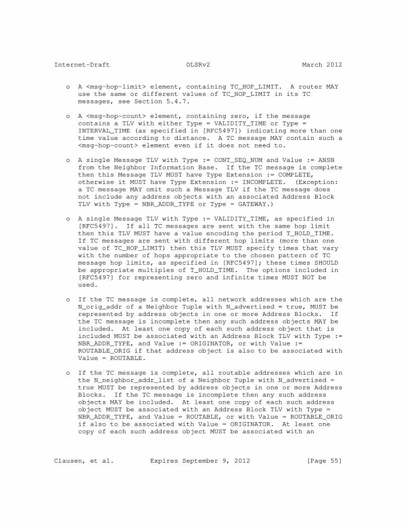
Internet-Draft OLSRv2 March 2012
o A <msg-hop-limit> element, containing TC_HOP_LIMIT. A router MAY use the same or different values of TC_HOP_LIMIT in its TC messages, see Section 5.4.7.
o A <msg-hop-count> element, containing zero, if the message contains a TLV with either Type = VALIDITY_TIME or Type = INTERVAL_TIME (as specified in [RFC5497]) indicating more than one time value according to distance. A TC message MAY contain such a <msg-hop-count> element even if it does not need to.
o A single Message TLV with Type := CONT_SEQ_NUM and Value := ANSN from the Neighbor Information Base. If the TC message is complete then this Message TLV MUST have Type Extension := COMPLETE, otherwise it MUST have Type Extension := INCOMPLETE. (Exception: a TC message MAY omit such a Message TLV if the TC message does not include any address objects with an associated Address Block TLV with Type = NBR_ADDR_TYPE or Type = GATEWAY.)
o A single Message TLV with Type := VALIDITY_TIME, as specified in [RFC5497]. If all TC messages are sent with the same hop limit then this TLV MUST have a value encoding the period T_HOLD_TIME. If TC messages are sent with different hop limits (more than one value of TC_HOP_LIMIT) then this TLV MUST specify times that vary with the number of hops appropriate to the chosen pattern of TC message hop limits, as specified in [RFC5497]; these times SHOULD be appropriate multiples of T_HOLD_TIME. The options included in [RFC5497] for representing zero and infinite times MUST NOT be used.
o If the TC message is complete, all network addresses which are the N_orig_addr of a Neighbor Tuple with N_advertised = true, MUST be represented by address objects in one or more Address Blocks. If the TC message is incomplete then any such address objects MAY be included. At least one copy of each such address object that is included MUST be associated with an Address Block TLV with Type := NBR_ADDR_TYPE, and Value := ORIGINATOR, or with Value := ROUTABLE_ORIG if that address object is also to be associated with Value = ROUTABLE.
o If the TC message is complete, all routable addresses which are in the N_neighbor_addr_list of a Neighbor Tuple with N_advertised = true MUST be represented by address objects in one or more Address Blocks. If the TC message is incomplete then any such address objects MAY be included. At least one copy of each such address object MUST be associated with an Address Block TLV with Type = NBR_ADDR_TYPE, and Value = ROUTABLE, or with Value = ROUTABLE_ORIG if also to be associated with Value = ORIGINATOR. At least one copy of each such address object MUST be associated with an
Clausen, et al. Expires September 9, 2012 [Page 55]

Internet-Draft OLSRv2 March 2012
Address Block TLV with Type = LINK_METRIC and Type Extension = LINK_METRIC_TYPE indicating an outgoing neighbor metric with value equal to the corresponding N_out_metric.
o If the TC message is complete, all network addresses which are the AL_net_addr of a Local Attached Network Tuple MUST be represented by address objects in one or more Address Blocks. If the TC message is incomplete then any such address objects MAY be included. At least one copy of each such address object MUST be associated with an Address Block TLV with Type := GATEWAY, and Value := AN_dist. At least one copy of each such address object MUST be associated with an Address Block TLV with Type = LINK_METRIC and Type Extension = LINK_METRIC_TYPE indicating an outgoing neighbor metric equal to the corresponding AL_metric.
A TC message MAY contain:
o A single Message TLV with Type := INTERVAL_TIME, as specified in [RFC5497]. If all TC messages are sent with the same hop limit then this TLV MUST have a value encoding the period TC_INTERVAL. If TC messages are sent with different hop limits, then this TLV MUST specify times that vary with the number of hops appropriate to the chosen pattern of TC message hop limits, as specified in [RFC5497]; these times MUST be appropriate multiples of TC_INTERVAL. The options included in [RFC5497] for representing zero and infinite times MUST NOT be used.
16.2. TC Message Transmission
A router with one or more OLSRv2 interfaces, and with any Neighbor Tuples with N_advertised = true, or with a non-empty Local Attached Network Set MUST generate TC messages. A router which does not have such information to advertise MUST also generate "empty" TC messages for a period A_HOLD_TIME after it last generated a non-empty TC message.
Complete TC messages are generated and transmitted periodically on all OLSRv2 interfaces, with a default interval between two consecutive TC message transmissions by the same router of TC_INTERVAL.
TC messages MAY be generated in response to a change in the information which they are to advertise, indicated by a change in the ANSN in the Neighbor Information Base. In this case a router MAY send a complete TC message, and if so MAY re-start its TC message schedule. Alternatively, a router MAY send an incomplete TC message with at least the newly advertised network addresses (i.e., not previously, but now, an N_orig_addr or in an N_neighbor_addr_list in
Clausen, et al. Expires September 9, 2012 [Page 56]

Internet-Draft OLSRv2 March 2012
a Neighbor Tuple with N_advertised = true, or an AL_net_addr) in its Address Blocks, with associated Address Block TLV(s). Note that a router cannot report removal of advertised content using an incomplete TC message.
When sending a TC message in response to a change of advertised network addresses, a router MUST respect a minimum interval of TC_MIN_INTERVAL between generated TC messages. Sending an incomplete TC message MUST NOT cause the interval between complete TC messages to be increased, and thus a router MUST NOT send an incomplete TC message if within TC_MIN_INTERVAL of the next scheduled complete TC message.
The generation of TC messages, whether scheduled or triggered by a change of contents, MAY be jittered as described in [RFC5148]. The values of MAXJITTER used MUST be:
o TP_MAXJITTER for periodic TC message generation;
o TT_MAXJITTER for responsive TC message generation.
16.3. TC Message Processing
On receiving a TC message on an OLSRv2 interface, the receiving router MUST then follow the processing and forwarding procedures, defined in Section 14.
If the message is considered for processing (Section 14.2), then a router MUST first check if the message is invalid for processing by this router, as defined in Section 16.3.1. A router MAY make a similar check before considering a message for forwarding, it MUST make those aspects of the check that apply to elements in the Message Header.
If the TC message is not invalid, then the TC message type specific processing, described in Section 16.3.2 MUST be applied. This will update its appropriate Interface Information Bases and its Router Information Base. Following this, if there are any changes in these Information Bases, then the processing in Section 17 MUST be performed.
16.3.1. TC Message Discarding
A received TC message is invalid for processing by this router if the message:
o Has an address length specified in the Message Header that is not equal to the length of the addresses used by this router.
Clausen, et al. Expires September 9, 2012 [Page 57]

Internet-Draft OLSRv2 March 2012
o Does not include a message originator address and a message sequence number.
o Does not include a hop count, and contains a multi-value TLV with Type = VALIDITY_TIME or Type = INTERVAL_TIME, as defined in [RFC5497].
o Does not have exactly one Message TLV with Type = VALIDITY_TIME.
o Has more than one Message TLV with Type = INTERVAL_TIME.
o Does not have a Message TLV with Type = CONT_SEQ_NUM and Type Extension = COMPLETE or Type Extension = INCOMPLETE, and contains at least one address object associated with an Address Block TLV with Type = NBR_ADDR_TYPE or Type = GATEWAY.
o Has more than one Message TLV with Type = CONT_SEQ_NUM and Type Extension = COMPLETE or Type Extension = INCOMPLETE.
o Has a message originator address that is partially owned by this router.
o Includes any address object with a prefix length which is not maximal (equal to the address length, in bits), associated with an Address Block TLV with Type = NBR_ADDR_TYPE and Value = ORIGINATOR or Value = ROUTABLE_ORIG.
o Includes any address object that represents a non-routable address, associated with an Address Block TLV with Type = NBR_ADDR_TYPE and Value = ROUTABLE or Value = ROUTABLE_ORIG.
o Includes any address object associated with an Address Block TLV with Type = NBR_ADDR_TYPE or Type = GATEWAY that also represents the message’s originator address.
o Includes any address object (including different copies of an address object, in the same or different Address Blocks) that is associated with an Address Block TLV with Type = NBR_ADDR_TYPE or Type = GATEWAY, that is also associated with more than one outgoing neighbor metric using a TLV with Type = LINK_METRIC and Type Extension = LINK_METRIC_TYPE.
o Associates any address object (including different copies of an address object, in the same or different Address Blocks) with more than one single hop count value using one or more Address Block TLV(s) with Type = GATEWAY.
Clausen, et al. Expires September 9, 2012 [Page 58]

Internet-Draft OLSRv2 March 2012
o Associates any address object (including different copies of an address object, in the same or different Address Blocks) with Address Block TLVs with Type = NBR_ADDR_TYPE and Type = GATEWAY.
A router MAY recognize additional reasons for identifying that a message is invalid. An invalid message MUST be silently discarded, without updating the router’s Information Bases.
16.3.2. TC Message Processing Definitions
When, according to Section 14.2, a TC message is to be "processed according to its type", this means that:
o If the TC message contains a Message TLV with Type = CONT_SEQ_NUM and Type Extension = COMPLETE, then processing according to Section 16.3.3 and then according to Section 16.3.4 is carried out.
o If the TC message contains a Message TLV with Type = CONT_SEQ_NUM and Type Extension = INCOMPLETE, then only processing according to Section 16.3.3 is carried out.
For the purposes of the TC message processing in Section 16.3.3 and Section 16.3.4:
o "validity time" is calculated from a VALIDITY_TIME Message TLV in the TC message according to the specification in [RFC5497]. All information in the TC message has the same validity time.
o "received ANSN" is defined as being the value of a Message TLV with Type = CONT_SEQ_NUM.
o "associated metric value" is defined for any address in the TC message as being either the outgoing neighbor metric value indicated by a TLV with Type = LINK_METRIC and Type Extension = LINK_METRIC_TYPE that is associated with any address object in the TC message that is equal to that address, or as UNKNOWN_METRIC otherwise. (Note that the rules in Section 16.3.1 make this definition unambiguous.)
o Comparisons of sequence numbers are carried out as specified in Section 21.
16.3.3. Initial TC Message Processing
The TC message is processed as follows:
Clausen, et al. Expires September 9, 2012 [Page 59]

Internet-Draft OLSRv2 March 2012
1. The Advertising Remote Router Set is updated according to Section 16.3.3.1. If the TC message is indicated as discarded in that processing then the following steps are not carried out.
2. The Router Topology Set is updated according to Section 16.3.3.2.
3. The Routable Address Topology Set is updated according to Section 16.3.3.3.
4. The Attached Network Set is updated according to Section 16.3.3.4.
16.3.3.1. Populating the Advertising Remote Router Set
The router MUST update its Advertising Remote Router Set as follows:
1. If there is an Advertising Remote Router Tuple with:
* AR_orig_addr = message originator address; AND
* AR_seq_number > received ANSN,
then the TC message MUST be discarded.
2. Otherwise:
1. If there is no Advertising Remote Router Tuple such that:
+ AR_orig_addr = message originator address;
then create an Advertising Remote Router Tuple with:
+ AR_orig_addr := message originator address.
2. This Advertising Remote Router Tuple (existing or new) is then modified as follows:
+ AR_seq_number := received ANSN;
+ AR_time := current time + validity time.
16.3.3.2. Populating the Router Topology Set
The router MUST update its Router Topology Set as follows:
1. For each address (henceforth advertised address) corresponding to one or more address objects with an associated Address Block TLV with Type = NBR_ADDR_TYPE and Value = ORIGINATOR or Value =
Clausen, et al. Expires September 9, 2012 [Page 60]

Internet-Draft OLSRv2 March 2012
ROUTABLE_ORIG, and that is not partially owned by this router, perform the following processing:
1. If the associated metric is UNKNOWN_METRIC then remove any Router Topology Tuple such that:
+ TR_from_orig_addr = message originator address; AND
+ TR_to_orig_addr = advertised address,
2. Otherwise if there is no Router Topology Tuple such that:
+ TR_from_orig_addr = message originator address; AND
+ TR_to_orig_addr = advertised address,
then create a new Router Topology Tuple with:
+ TR_from_orig_addr := message originator address;
+ TR_to_orig_addr := advertised address.
3. This Router Topology Tuple (existing or new) is then modified as follows:
+ TR_seq_number := received ANSN;
+ TR_metric := associated link metric;
+ TR_time := current time + validity time.
16.3.3.3. Populating the Routable Address Topology Set
The router MUST update its Routable Address Topology Set as follows:
1. For each network address (henceforth advertised address) corresponding to one or more address objects with an associated Address Block TLV with Type = NBR_ADDR_TYPE and Value = ROUTABLE or Value = ROUTABLE_ORIG, and that is not partially owned by this router, perform the following processing:
1. If the associated metric is UNKNOWN_METRIC then remove any Routable Address Topology Tuple such that:
+ TA_from_orig_addr = message originator address; AND
+ TA_dest_addr = advertised address.
Clausen, et al. Expires September 9, 2012 [Page 61]

Internet-Draft OLSRv2 March 2012
2. Otherwise if there is no Routable Address Topology Tuple such that:
+ TA_from_orig_addr = message originator address; AND
+ TA_dest_addr = advertised address,
then create a new Routable Address Topology Tuple with:
+ TA_from_orig_addr := message originator address;
+ TA_dest_addr := advertised address.
3. This Routable Address Topology Tuple (existing or new) is then modified as follows:
+ TA_seq_number := received ANSN;
+ TA_metric := associated link metric;
+ TA_time := current time + validity time.
16.3.3.4. Populating the Attached Network Set
The router MUST update its Attached Network Set as follows:
1. For each network address (henceforth attached address) corresponding to one or more address objects with an associated Address Block TLV with Type = GATEWAY, and that is not fully owned by this router, perform the following processing:
1. If the associated metric is UNKNOWN_METRIC then remove any Attached Network Tuple such that:
+ AN_net_addr = attached address; AND
+ AN_orig_addr = message originator address.
2. Otherwise if there is no Attached Network Tuple such that:
+ AN_net_addr = attached address; AND
+ AN_orig_addr = message originator address,
then create a new Attached Network Tuple with:
+ AN_net_addr := attached address;
Clausen, et al. Expires September 9, 2012 [Page 62]

Internet-Draft OLSRv2 March 2012
+ AN_orig_addr := message originator address.
3. This Attached Network Tuple (existing or new) is then modified as follows:
+ AN_seq_number := received ANSN;
+ AN_dist := the Value of the associated GATEWAY TLV;
+ AN_metric := associated link metric;
+ AN_time := current time + validity time.
16.3.4. Completing TC Message Processing
The TC message is processed as follows:
1. The Router Topology Set is updated according to Section 16.3.4.1.
2. The Routable Address Topology Set is updated according to Section 16.3.4.2.
3. The Attached Network Set is updated according to Section 16.3.4.3.
16.3.4.1. Purging the Router Topology Set
The Router Topology Set MUST be updated as follows:
1. Any Router Topology Tuples with:
* TR_from_orig_addr = message originator address; AND
* TR_seq_number < received ANSN,
MUST be removed.
16.3.4.2. Purging the Routable Address Topology Set
The Routable Address Topology Set MUST be updated as follows:
1. Any Routable Address Topology Tuples with:
* TA_from_orig_addr = message originator address; AND
* TA_seq_number < received ANSN,
MUST be removed.
Clausen, et al. Expires September 9, 2012 [Page 63]
Internet-Draft OLSRv2 March 2012
16.3.4.3. Purging the Attached Network Set
The Attached Network Set MUST be updated as follows:
1. Any Attached Network Tuples with:
* AN_orig_addr = message originator address; AND
* AN_seq_number < received ANSN,
MUST be removed.
17. Information Base Changes
The changes described in the following sections MUST be carried out when any Information Base changes as indicated.
17.1. Originator Address Changes
If the router changes its originator address, then:
1. If there is no Originator Tuple with:
* O_orig_addr = old originator address
then create an Originator Tuple with:
* O_orig_addr := old originator address
The Originator Tuple (existing or new) with:
* O_orig_addr = new originator address
is then modified as follows:
* O_time := current time + O_HOLD_TIME
17.2. Link State Changes
The consistency of a Link Tuple MUST be maintained according to the following rules, in addition to those in [RFC6130]:
o If L_status = HEARD or L_status = SYMMETRIC, then L_in_metric MUST be set (by a process outside this specification).
o If L_status != SYMMETRIC, then set L_mpr_selector := false.
Clausen, et al. Expires September 9, 2012 [Page 64]

Internet-Draft OLSRv2 March 2012
o If L_out_metric = UNKNOWN_METRIC, then L_status MUST NOT equal SYMMETRIC; set L_SYM_time := expired if this would otherwise be the case.
17.3. Neighbor State Changes
The consistency of a Neighbor Tuple MUST be maintained according to the following rules, in addition to those in [RFC6130]:
1. If N_symmetric = true, then N_in_metric MUST equal the minimum value of all L_in_metric of corresponding Link Tuples with L_status = SYMMETRIC and L_in_metric != UNKNOWN_METRIC. If there are no such Link Tuples then N_in_metric MUST equal UNKNOWN_METRIC.
2. If N_symmetric = true, then N_out_metric MUST equal the minimum value of all L_out_metric of corresponding Link Tuples with L_status = SYMMETRIC and L_out_metric != UNKNOWN_METRIC. If there are no such Link Tuples then N_out_metric MUST equal UNKNOWN_METRIC.
3. If N_symmetric = false, then N_flooding_mpr, N_routing_mpr, N_mpr_selector and N_advertised MUST all be equal to false.
4. If N_mpr_selector = true, then N_advertised MUST be equal to true.
5. If N_symmetric = true, N_out_metric != UNKNOWN_METRIC and N_mpr_selector = false, then a router MAY select N_advertised = true or N_advertised = false. The more neighbors that are advertised, the larger TC messages become, but the more redundancy is available for routing. A router SHOULD consider the nature of its network in making such a decision, and SHOULD avoid unnecessary changes in advertising status, which may result both in additional TC messages having to be sent by its neighbors, and in unnecessary changes to routing, which will have similar effects to other forms of topology changes in the MANET.
17.4. Advertised Neighbor Changes
The router MUST increment the ANSN in the Neighbor Information Base whenever:
1. Any Neighbor Tuple changes its N_advertised value, or any Neighbor Tuple with N_advertised = true is removed.
2. Any Neighbor Tuple with N_advertised = true changes its N_orig_addr, or has any routable address is added to or removed
Clausen, et al. Expires September 9, 2012 [Page 65]
Internet-Draft OLSRv2 March 2012
from N_neighbor_addr_list.
3. Any Neighbor Tuple with N_advertised = true has N_out_metric changed.
4. There is any change to the Local Attached Network Set.
17.5. Advertising Remote Router Tuple Expires
The Router Topology Set, the Routable Address Topology Set and the Attached Network Set MUST be changed when an Advertising Remote Router Tuple expires (AR_time is reached). The following changes are required before the Advertising Remote Router Tuple is removed:
1. All Router Topology Tuples with:
* TR_from_orig_addr = AR_orig_addr of the Advertising Remote Router Tuple
are removed.
2. All Routable Address Topology Tuples with:
* TA_from_orig_addr = AR_orig_addr of the Advertising Remote Router Tuple
are removed.
3. All Attached Network Tuples with:
* AN_orig_addr = AR_orig_addr of the Advertising Remote Router Tuple
are removed.
17.6. Neighborhood Changes and MPR Updates
The sets of symmetric 1-hop neighbors selected as flooding MPRs and routing MPRs MUST satisfy the conditions defined in Section 18. To ensure this:
1. The set of flooding MPRs of a router MUST be recalculated if:
* A Link Tuple is added with L_status = SYMMETRIC and L_out_metric != UNKNOWN_METRIC, OR;
* A Link Tuple with L_status = SYMMETRIC and L_out_metric != UNKNOWN_METRIC is removed, OR;
Clausen, et al. Expires September 9, 2012 [Page 66]

Internet-Draft OLSRv2 March 2012
* A Link Tuple with L_status = SYMMETRIC and L_out_metric != UNKNOWN_METRIC changes to having L_status = HEARD, L_status = LOST or L_out_metric = UNKNOWN_METRIC, OR;
* A Link Tuple with L_status = HEARD or L_status = LOST changes to having L_status = SYMMETRIC and L_out_metric != UNKNOWN_METRIC, OR;
* The flooding MPR selection process uses metric values (see Section 18.4) and the L_out_metric of any Link Tuple with L_status = SYMMETRIC changes, OR;
* The N_will_flooding of a Neighbor Tuple with N_symmetric = true and N_out_metric != UNKNOWN_METRIC changes from WILL_NEVER to any other value, OR;
* The N_will_flooding of a Neighbor Tuple with N_flooding_mpr = true changes to WILL_NEVER from any other value, OR;
* The N_will_flooding of a Neighbor Tuple with N_symmetric = true, N_out_metric != UNKNOWN_METRIC, and N_flooding_mpr = false changes to WILL_ALWAYS from any other value, OR;
* A 2-Hop Tuple with N2_out_metric != UNKNOWN_METRIC is added or removed, OR;
* The flooding MPR selection process uses metric values (see Section 18.4) and the N2_out_metric of any 2-Hop Tuple changes.
2. Otherwise, the set of flooding MPRs of a router MAY be recalculated if the N_will_flooding of a Neighbor Tuple with N_symmetric = true changes in any other way; it SHOULD be recalculated if N_flooding_mpr = false and this is an increase in N_will_flooding or if N_flooding_mpr = true and this is a decrease in N_will_flooding.
3. The set of routing MPRs of a router MUST be recalculated if:
* A Neighbor Tuple is added with N_symmetric = true and N_in_metric != UNKNOWN_METRIC, OR;
* A Neighbor Tuple with N_symmetric = true and N_in_metric != UNKNOWN_METRIC is removed, OR;
* A Neighbor Tuple with N_symmetric = true and N_in_metric != UNKNOWN_METRIC changes to having N_symmetric = false, OR;
Clausen, et al. Expires September 9, 2012 [Page 67]

Internet-Draft OLSRv2 March 2012
* A Neighbor Tuple with N_symmetric = false changes to having N_symmetric = true and N_in_metric != UNKNOWN_METRIC, OR;
* The N_in_metric of any Neighbor Tuple with N_symmetric = true changes, OR;
* The N_will_routing of a Neighbor Tuple with N_symmetric = true and N_in_metric != UNKNOWN_METRIC changes from WILL_NEVER to any other value, OR;
* The N_will_routing of a Neighbor Tuple with N_routing_mpr = true changes to WILL_NEVER from any other value, OR;
* The N_will_routing of a Neighbor Tuple with N_symmetric = true, N_in_metric != UNKNOWN_METRIC and N_routing_mpr = false changes to WILL_ALWAYS from any other value, OR;
* A 2-Hop Tuple with N2_in_metric != UNKNOWN_METRIC is added or removed, OR;
* The N2_in_metric of any 2-Hop Tuple changes.
4. Otherwise, the set of routing MPRs of a router MAY be recalculated if the N_will_routing of a Neighbor Tuple with N_symmetric = true changes in any other way; it SHOULD be recalculated if N_routing_mpr = false and this is an increase in N_will_routing or if N_routing_mpr = true and this is a decrease in N_will_routing.
If either set of MPRs of a router is recalculated, this MUST be as described in Section 18.
17.7. Routing Set Updates
The Routing Set MUST be updated, as described in Section 19, when changes in the Local Information Base, the Neighborhood Information Base or the Topology Information Base indicate a change (including of any potentially used outgoing neighbor metric values) of the known symmetric links and/or attached networks in the MANET, hence changing the Topology Graph. It is sufficient to consider only changes which affect at least one of:
o The Local Interface Set for an OLSRv2 interface, if the change removes any network address in an I_local_iface_addr_list. In this case, unless the OLSRv2 interface is removed, it may not be necessary to do more than replace such network addresses, if used, by an alternative network address from the same I_local_iface_addr_list.
Clausen, et al. Expires September 9, 2012 [Page 68]

Internet-Draft OLSRv2 March 2012
o The Local Attached Set, if the change removes any AL_net_addr which is also an AN_net_addr. In this case it may not be necessary to do more than add Routing Tuples with R_dest_addr equal to that AN_net_addr.
o The Link Set of any OLSRv2 interface, considering only Link Tuples which have, or just had, L_status = SYMMETRIC and L_out_metric != UNKNOWN_METRIC (including removal of such Link Tuples).
o The Neighbor Set of the router, considering only Neighbor Tuples that have, or just had, N_symmetric = true and N_out_metric != UNKNOWN_METRIC, and do not have N_orig_addr = unknown.
o The 2-Hop Set of any OLSRv2 interface, if used in the creation of the Routing Set, and if the change affects any 2-Hop Tuples with N2_out_metric != UNKNOWN_METRIC.
o The Router Topology Set of the router.
o The Routable Address Topology Set of the router.
o The Attached Network Set of the router.
18. Selecting MPRs
Each router MUST select, from among its willing symmetric 1-hop neighbors, two subsets of these routers, as flooding and routing MPRs. This selection is recorded in the router’s Neighbor Set, and reported in the router’s HELLO messages. Routers MAY select their MPRs by any process that satisfies the conditions which follow, which may, but need not, use the organization of the data described. Routers can freely interoperate whether they use the same or different MPR selection algorithms.
Only flooding MPRs forward control messages flooded through the MANET, thus effecting a flooding reduction, an optimization of the flooding mechanism, known as MPR flooding. Routing MPRs are used to effect a topology reduction in the MANET. (If no such reduction is required then a router can select all of its relevant neighbors as routing MPRs.) Consequently, while it is not essential that these two sets of MPRs are minimal, keeping the numbers of MPRs small ensures that the overhead of this protocol is kept to a minimum.
18.1. Overview
MPRs are selected according to the following steps, defined in the following sections:
Clausen, et al. Expires September 9, 2012 [Page 69]

Internet-Draft OLSRv2 March 2012
o A data structure known as a Neighbor Graph is defined.
o The properties of an MPR Set derived from a Neighbor Graph are defined. Any algorithm that creates an MPR Set that satisfies these properties is a valid MPR selection algorithm. An example algorithm that creates such an MPR Set is given in Appendix A.
o How to create a Neighbor Graph for each interface based on the corresponding Interface Information Base is defined, and how to combine the resulting MPR Sets to determine the router’s flooding MPRs and record those in the router’s Neighbor Set.
o How to create a single Neighbor Graph based on all Interface Information Bases and the Neighbor Information Base is defined, and how to record the resulting MPR Set as the router’s routing MPRs in the router’s Neighbor Set.
o A specification as to when MPRs MUST be calculated is given.
When a router selects its MPRs it MAY consider any characteristics of its neighbors that it is aware of. In particular it SHOULD consider the willingness of the neighbor, as recorded by the corresponding N_will_flooding or N_will_routing value, as appropriate, preferring neighbors with higher values. (Note that willingness values equal to WILL_NEVER and WILL_ALWAYS are always considered, as described.) However, a router MAY consider other characteristics to have a greater significance.
Each router MAY select its flooding and routing MPRs independently from each other, or coordinate its selections. A router MAY make its MPR selections independently of the MPR selection by other routers, or it MAY, for example, give preference to routers that either are, or are not, already selected as MPRs by other routers.
18.2. Neighbor Graph
A Neighbor Graph is a structure defined here as consisting of sets N1 and N2 and some associated metric and willingness values. Elements of set N1 represent willing symmetric 1-hop neighbors, and elements of set N2 represent addresses of a symmetric 2-hop neighbor.
A Neighbor Graph has the following properties:
o It contains two disjoint sets N1 and N2.
o For each element x in N1 there is an associated willingness value W(x) such that WILL_NEVER < W(x) <= WILL_ALWAYS.
Clausen, et al. Expires September 9, 2012 [Page 70]

Internet-Draft OLSRv2 March 2012
o For each element x in N1 there is an associated metric d1(x) > 0.
o For some elements y in N2 there is an associated metric d1(y) > 0. (Other elements y in N2 have undefined d1(y), this may be considered to be infinite.)
o For each element x in N1 there is a subset N2(x) of elements of N2; this subset may be empty. For each x in N1 and each y in N2(x) there is an associated metric d2(x,y) > 0. (For other x in N1 and y in N2, d2(x,y) is undefined, and may be considered infinite.)
o N2 is equal to the union of all the N2(x) for all x in N1, i.e. for each y in N2 there is at least one x in N1 such that y is in N2(x).
It is convenient to also define:
o For each y in N2 the set N1(y) that contains x in N1 if and only if y is in N2(x). From the final property above, N1(y) is not empty.
o For each x in N1 and y in N2, if d2(x,y) is defined then d(x,y) := d1(x)+d2(x,y), otherwise d(x,y) is not defined. (Thus d(x,y) is defined if y is in N2(x), or equivalently if x is in N1(y).)
o For any subset S of N1, and for each y in N2, the metric d(y,S) is the minimum value of d1(y), if defined, and of all d(x,y) for x in N1(y) and in S. If there are no such metrics to take the minimum value of, then d(y,S) is undefined (may be considered to be infinite). From the final property above, d(y,N1) is defined for all y.
18.3. MPR Properties
Given a Neighbor Graph as defined in Section 18.2, an MPR Set for that Neighbor Graph is a subset M of the set N1 that satisfies the following properties:
o If x in N1 has W(x) = WILL_ALWAYS then x is in M.
o For any y in N2 that does not have a defined d1(y), there is at least one element in M that is also in N1(y). This is equivalent to the requirement that d(y,M) is defined.
o For any y in N2, d(y,M) = d(y,N1).
These two properties correspond first to that the MPR Set consists of
Clausen, et al. Expires September 9, 2012 [Page 71]

Internet-Draft OLSRv2 March 2012
a set of symmetric 1-hop neighbors that cover all the symmetric 2-hop neighbors, and second that they do so retaining a minimum distance route (1-hop, if present, or 2-hop) to each symmetric 2-hop neighbor.
Note that if M is an MPR Set, then so is any subset of N1 that contains M, and also that N1 is always an MPR Set. An MPR Set may be empty, but cannot be empty if N2 contains any elements y that do not have a defined d1(y).
18.4. Flooding MPRs
Whenever flooding MPRs are to be calculated, an implementation MUST determine and record a set of flooding MPRs that is equivalent to one calculated as described in this section.
The calculation of flooding MPRs need not use link metrics, or equivalently may use link metrics with a fixed value, here taken to be 1. However, links with unknown metric (L_out_metric = UNKNOWN_METRIC) MUST NOT be used even if link metrics are otherwise not used.
Routers MAY make individual decisions as to whether to use link metrics for the calculation of flooding MPRs. A router MUST use the same approach to the choice of whether to use link metrics for all links, i.e., in the cases indicated by A or B, the same choice MUST be made in each case.
For each OLSRv2 interface (the "current interface") define a Neighbor Graph as defined in Section 18.2 according to the following:
o Define a reachable Link Tuple to be a Link Tuple in the Link Set for the current interface with L_status = SYMMETRIC and L_out_metric != UNKNOWN_METRIC.
o Define an allowed Link Tuple to be a reachable Link Tuple whose corresponding Neighbor Tuple has N_will_flooding > WILL_NEVER.
o Define an allowed 2-Hop Tuple to be a 2-Hop Tuple in the 2-Hop Set for the current interface for which N2_out_metric != UNKNOWN_METRIC and there is an allowed Link Tuple with L_neighbor_iface_addr_list = N2_neighbor_iface_addr_list.
o Define an element of N1 for each allowed Link Tuple. This then defines the corresponding Link Tuple for each element of N1 and the corresponding Neighbor Tuple for each element of N1, being the Neighbor Tuple corresponding to that Link Tuple.
Clausen, et al. Expires September 9, 2012 [Page 72]

Internet-Draft OLSRv2 March 2012
o For each element x in N1, define W(x) := N_will_flooding of the corresponding Neighbor Tuple.
o For each element x in N1, define d1(x) as either:
A. L_out_metric of the corresponding Link Tuple, OR;
B. 1.
o Define an element of N2 for each network address that is the N2_2hop_addr of one or more allowed 2-Hop Tuples. This then defines the corresponding address for each element of N2.
o For each element y in N2, if the corresponding address is in the N_neighbor_addr_list of a Neighbor Tuple that corresponds to one or more reachable Link Tuples, then define d1(y) as either:
A. the minimum value of the L_out_metric of those Link Tuples, OR;
B. 1.
Otherwise d1(y) is not defined. In the latter case, where d1(y) := 1, all such y in N2 may instead be removed from N2.
o For each element x in N1, define N2(x) as the set of elements y in N2 whose corresponding address is the N2_2hop_addr of an allowed 2-Hop Tuple that has N2_neighbor_iface_addr_list = L_neighbor_iface_addr_list of the Link Tuple corresponding to x. For all such x and y, define d2(x,y) as either:
A. N2_out_metric of that 2-Hop Tuple, OR;
B. 1.
It is up to an implementation to decide how to label each element of N1 or N2. For example an element of N1 may be labeled with one or more addresses from the corresponding L_neighbor_iface_addr_list, or with a pointer or reference to the corresponding Link Tuple.
Using these Neighbor Graphs, flooding MPRs are selected and recorded by:
o For each OLSRv2 interface, determine an MPR Set as specified in Section 18.3.
o A Neighbor Tuple represents a flooding MPR and has N_flooding_mpr := true (otherwise N_flooding_mpr := false) if and only if that
Clausen, et al. Expires September 9, 2012 [Page 73]

Internet-Draft OLSRv2 March 2012
Neighbor Tuple corresponds to an element in an MPR Set created for any interface as described above. That is, the overall set of flooding MPRs is the union of the sets of flooding MPRs for all OLSRv2 interfaces.
A router MAY select its flooding MPRs for each OLSRv2 interface independently, or it MAY coordinate its MPR selections across its OLSRv2 interfaces, as long as the required condition is satisfied for each OLSRv2 interface. One such coordinated approach is to process the OLSRv2 interfaces sequentially, and for each OLSRv2 interface start with flooding MPRs selected (and not removable) if the neighbor has been already selected as an MPR for an OLSRv2 interface that has already been processed. The algorithm specified in Appendix A can be used in this way.
18.5. Routing MPRs
Whenever routing MPRs are to be calculated, an implementation MUST determine and record a set of routing MPRs that is equivalent to one calculated as described in this section.
Define a single Neighbor Graph as defined in Section 18.2 according to the following:
o Define a reachable Neighbor Tuple to be a Neighbor Tuple with N_symmetric = true and N_in_metric != UNKNOWN_METRIC.
o Define an allowed Neighbor Tuple to be a reachable Neighbor Tuple with N_will_routing > WILL_NEVER.
o Define an allowed 2-Hop Tuple to be a 2-Hop Tuple in the 2-Hop Set for any OLSRv2 interface with N2_in_metric != UNKNOWN_METRIC and for which there is an allowed Neighbor Tuple with N_neighbor_addr_list containing N2_neighbor_iface_addr_list.
o Define an element of N1 for each allowed Neighbor Tuple. This then defines the corresponding Neighbor Tuple for each element of N1.
o For each element x in N1, define W(x) := N_will_routing of the corresponding Neighbor Tuple.
o For each element x in N1, define d1(x) := N_in_metric of the corresponding Neighbor Tuple.
o Define an element of N2 for each network address that is the N2_2hop_addr of one or more allowed 2-Hop Tuples. This then defines the corresponding address for each element of N2.
Clausen, et al. Expires September 9, 2012 [Page 74]

Internet-Draft OLSRv2 March 2012
o For each element y in N2, if the corresponding address is in the N_neighbor_addr_list of a reachable Neighbor Tuple, then define d1(y) to be the N_in_metric of that Neighbor Tuple, otherwise d1(y) is not defined.
o For each element x in N1, define N2(x) as the set of elements y in N2 whose corresponding address is the N2_2hop_addr of an allowed 2-Hop Tuple that has N2_neighbor_iface_addr_list contained in N_neighbor_addr_list of the Neighbor Tuple corresponding to x. For all such x and y, define d2(x,y) := N2_out_metric of that 2-Hop Tuple.
It is up to an implementation to decide how to label each element of N1 or N2. For example an element of N1 may be labeled with one or more addresses from the corresponding N_neighbor_addr_list, or with a pointer or reference to the corresponding Neighbor Tuple.
Using these Neighbor Graphs, routing MPRs are selected and recorded according to the following:
o Determine an MPR Set as specified in Section 18.3.
o A Neighbor Tuple represents a routing MPR and has N_routing_mpr := true (otherwise N_routing_mpr := false) if and only if that Neighbor Tuple corresponds to an element in the MPR Set created as described above.
18.6. Calculating MPRs
A router MUST recalculate each of its sets of MPRs whenever the currently selected set of MPRs does not still satisfy the required conditions. It MAY recalculate its MPRs if the current set of MPRs is still valid, but could be more efficient. Sufficient conditions to recalculate a router’s sets of MPRs are given in Section 17.6.
19. Routing Set Calculation
The Routing Set of a router is populated with Routing Tuples that represent paths from that router to all destinations in the network. These paths are calculated based on the Network Topology Graph, which is constructed from information in the Information Bases, obtained via HELLO and TC message exchange.
Changes to the Routing Set do not require any messages to be transmitted. The state of the Routing Set SHOULD, however, be reflected in the IP routing table by adding and removing entries from that routing table as appropriate. Only appropriate Routing Tuples (in particular only those that represent local links or paths to
Clausen, et al. Expires September 9, 2012 [Page 75]

Internet-Draft OLSRv2 March 2012
routable addresses) need be reflected in the IP routing table.
19.1. Network Topology Graph
The Network Topology Graph is formed from information from the router’s Local Interface Set, Link Sets for OLSRv2 interfaces, Neighbor Set, Router Topology Set, Routable Address Topology Set and Attached Network Set. The Network Topology Graph MAY also use information from the router’s 2-Hop Sets for OLSRv2 interfaces. The Network Topology Graph forms the router’s topological view of the network in form of a directed graph. Each edge in that graph has a metric value. The Network Topology Graph has a "backbone" (within which minimum total metric routes will be constructed) containing the following edges:
o Edges X -> Y for all possible Y, and one X per Y, such that:
* Y is the N_orig_addr of a Neighbor Tuple; AND
* N_orig_addr is not unknown;
* X is in the I_local_iface_addr_list of a Local Interface Tuple; AND
* There is a Link Tuple with L_status = SYMMETRIC and L_out_metric != UNKNOWN_METRIC such that this Neighbor Tuple and this Local Interface Tuple correspond to it. A network address from L_neighbor_iface_addr_list will be denoted R in this case.
It SHOULD be preferred, where possible, to select R = S and X from the Local Interface Tuple corresponding to the Link Tuple from which R was selected. The metric for such an edge is the corresponding N_out_metric.
o All edges W -> U such that:
* W is the TR_from_orig_addr of a Router Topology Tuple; AND
* U is the TR_to_orig_addr of the same Router Topology Tuple.
The metric of such an edge is the corresponding TR_metric.
The Network Topology Graph is further "decorated" with the following edges. If a network address S, V, Z or T equals a network address Y or W, then the edge terminating in the network address S, V, Z or T MUST NOT be used in any path.
Clausen, et al. Expires September 9, 2012 [Page 76]

Internet-Draft OLSRv2 March 2012
o Edges X -> S for all possible S, and one X per S, such that:
* S is in the N_neighbor_addr_list of a Neighbor Tuple; AND
* X is in the I_local_iface_addr_list of a Local Interface Tuple; AND
* There is a Link Tuple with L_status = SYMMETRIC and L_out_metric != UNKNOWN_METRIC such that this Neighbor Tuple and this Local Interface Tuple correspond to it. A network address from L_neighbor_iface_addr_list will be denoted R in this case.
It SHOULD be preferred, where possible, to select R = S and X from the Local Interface Tuple corresponding to the Link Tuple from which R was selected. The metric for such an edge is the corresponding N_out_metric.
o All edges W -> V such that:
* W is the TA_from_orig_addr of a Routable Address Topology Tuple; AND
* V is the TA_dest_addr of the same Routable Address Topology Tuple.
The metric for such an edge is the corresponding TA_metric.
o All edges W -> T such that:
* W is the AN_orig_addr of an Attached Network Tuple; AND
* T is the AN_net_addr of the same Attached Network Tuple.
The metric for such an edge is the corresponding AN_metric.
o (OPTIONAL) All edges Y -> Z such that:
* Z is a routable address and is the N2_2hop_addr of a 2-Hop Tuple with N2_out_metric != UNKNOWN_METRIC; AND
* Y is the N_orig_addr of the corresponding Neighbor Tuple; AND
* This Neighbor Tuple has N_will_routing not equal to WILL_NEVER.
A path terminating with such an edge MUST NOT be used in preference to any other path. The metric for such an edge is the corresponding N2_out_metric.
Clausen, et al. Expires September 9, 2012 [Page 77]
Internet-Draft OLSRv2 March 2012
Any part of the Topology Graph which is not connected to a local network address X is not used. Only one selection X SHOULD be made from each I_local_iface_addr_list, and only one selection R SHOULD be made from any L_neighbor_iface_addr_list. All edges have a hop count of 1, except edges W -> T that have a hop count of the corresponding value of AN_dist.
19.2. Populating the Routing Set
The Routing Set MUST contain the shortest paths for all destinations from all local OLSRv2 interfaces using the Network Topology Graph. This calculation MAY use any algorithm, including any means of choosing between paths of equal total metric. (In the case of two paths of equal total metric but differing hop counts, the path with the lower hop count SHOULD be used.)
Using the notation of Section 19.1, initially "backbone" paths using only edges X -> Y and W -> U need be constructed (using a minimum distance algorithm). Then paths using only a final edge of the other types may be added. These MUST NOT replace backbone paths with the same destination (and paths terminating in an edge Y -> Z SHOULD NOT replace paths with any other form of terminating edge).
Each path will correspond to a Routing Tuple. These will be of two types. The first type will represent single edge paths, of type X -> S or X -> Y, by:
o R_local_iface_addr := X;
o R_next_iface_addr := R;
o R_dest_addr := S or Y;
o R_dist := 1;
o R_metric := edge metric,
where R is as defined in Section 19.1 for these types of edges.
The second type will represent a multiple edge path, which will always have first edge of type X -> Y, and will have final edge of type W -> U, W -> V, W -> T or Y -> Z. The Routing Tuple will be:
o R_local_iface_addr := X;
o R_next_iface_addr := Y;
Clausen, et al. Expires September 9, 2012 [Page 78]

Internet-Draft OLSRv2 March 2012
o R_dest_addr := U, V, T or Z;
o R_dist := the total hop count of all edges in the path;
o R_metric := the total metric of all edges in the path.
Finally, Routing Tuples of the second type whose R_dest_addr is not routable MAY be discarded.
An example algorithm for calculating the Routing Set of a router is given in Appendix B.
20. Proposed Values for Parameters
This protocol uses all parameters defined in [RFC6130] and additional parameters and defined in this specification. All but one (RX_HOLD_TIME) of these additional parameters are router parameters as defined in [RFC6130]. The proposed values of the additional parameters defined in the following sections are appropriate to the case where all parameters (including those defined in [RFC6130]) have a single value. Proposed values for parameters defined in [RFC6130] are given in that specification.
20.1. Local History Time Parameters
o O_HOLD_TIME := 30 seconds
20.2. Message Interval Parameters
o TC_INTERVAL := 5 seconds
o TC_MIN_INTERVAL := TC_INTERVAL/4
20.3. Advertised Information Validity Time Parameters
o T_HOLD_TIME := 3 x TC_INTERVAL
o A_HOLD_TIME := T_HOLD_TIME
20.4. Received Message Validity Time Parameters
o RX_HOLD_TIME := 30 seconds
o P_HOLD_TIME := 30 seconds
o F_HOLD_TIME := 30 seconds
Clausen, et al. Expires September 9, 2012 [Page 79]
Internet-Draft OLSRv2 March 2012
20.5. Jitter Time Parameters
o TP_MAXJITTER := HP_MAXJITTER
o TT_MAXJITTER := HT_MAXJITTER
o F_MAXJITTER := TT_MAXJITTER
20.6. Hop Limit Parameter
o TC_HOP_LIMIT := 255
20.7. Willingness Parameter
o WILL_FLOODING := WILL_DEFAULT
o WILL_ROUTING := WILL_DEFAULT
21. Sequence Numbers
Sequence numbers are used in this specification for the purpose of discarding "old" information, i.e., messages received out of order. However with a limited number of bits for representing sequence numbers, wrap-around (that the sequence number is incremented from the maximum possible value to zero) will occur. To prevent this from interfering with the operation of this protocol, the following MUST be observed when determining the ordering of sequence numbers.
The term MAXVALUE designates in the following one more than the largest possible value for a sequence number. For a 16 bit sequence number (as are those defined in this specification) MAXVALUE is 65536.
The sequence number S1 is said to be "greater than" the sequence number S2 if:
o S1 > S2 AND S1 - S2 < MAXVALUE/2 OR
o S2 > S1 AND S2 - S1 > MAXVALUE/2
When sequence numbers S1 and S2 differ by MAXVALUE/2 their ordering cannot be determined. In this case, which should not occur, either ordering may be assumed.
Thus when comparing two messages, it is possible - even in the presence of wrap-around - to determine which message contains the most recent information.
Clausen, et al. Expires September 9, 2012 [Page 80]

Internet-Draft OLSRv2 March 2012
22. Extensions
An extension to this protocol will need to interact with this specification, and possibly also with [RFC6130]. This protocol is designed to permit such interactions, in particular:
o Through accessing, and possibly extending, the information in the Information Bases. All updates to the elements specified in this specification are subject to the constraints specified in [RFC6130] and Appendix D.
o Through accessing an outgoing message prior to it being transmitted over any OLSRv2 interface, and to add information to it as specified in [RFC5444]. This MAY include Message TLVs and/or network addresses with associated Address Block TLVs. (Network addresses without new associated TLVs SHOULD NOT be added to messages.) This may, for example, be to allow a security protocol, as suggested in Section 23, to add a TLV containing a cryptographic signature to the message.
o Through accessing an incoming message, and potentially discarding it prior to processing by this protocol. This may, for example, allow a security protocol, as suggested in Section 23, to perform verification of message signatures and prevent processing and/or forwarding of unverifiable messages by this protocol.
o Through accessing an incoming message after it has been completely processed by this protocol. In particular, this may allow a protocol which has added information, by way of inclusion of appropriate TLVs, or of network addresses associated with new TLVs, access to such information after appropriate updates have been recorded in the Information Bases in this protocol.
o Through requesting that a message be generated at a specific time. In that case, message generation MUST still respect the constraints in [RFC6130] and Section 5.4.3.
23. Security Considerations
Currently, this protocol does not specify any special security measures. As a proactive routing protocol, this protocol is a potential target for various attacks. Various possible vulnerabilities are discussed in this section.
23.1. Confidentiality
This protocol periodically MPR floods topological information to all routers in the network. Hence, if used in an unprotected wireless
Clausen, et al. Expires September 9, 2012 [Page 81]

Internet-Draft OLSRv2 March 2012
network, the network topology is revealed to anyone who listens to the control messages.
In situations where the confidentiality of the network topology is of importance, regular cryptographic techniques, such as exchange of OLSRv2 control traffic messages encrypted by PGP [RFC4880] or encrypted by some shared secret key, can be applied to ensure that control traffic can be read and interpreted by only those authorized to do so.
23.2. Integrity
Each router is injecting topological information into the network through transmitting HELLO messages and, for some routers, TC messages. If some routers for some reason, malicious or malfunction, inject invalid control traffic, network integrity may be compromised. Therefore, message authentication is recommended.
Different such situations may occur, for instance:
1. A router generates TC messages, advertising links to non-neighbor routers;
2. A router generates TC messages, pretending to be another router;
3. A router generates HELLO messages, advertising non-neighbor routers;
4. A router generates HELLO messages, pretending to be another router;
5. A router forwards altered control messages;
6. A router does not forward control messages;
7. A router does not select multipoint relays correctly;
8. A router forwards broadcast control messages unaltered, but does not forward unicast data traffic;
9. A router "replays" previously recorded control traffic from another router.
Authentication of the originator router for control messages (for situations 2, 4 and 5) and on the individual links announced in the control messages (for situations 1 and 3) may be used as a countermeasure. However to prevent routers from repeating old (and correctly authenticated) information (situation 9) temporal
Clausen, et al. Expires September 9, 2012 [Page 82]

Internet-Draft OLSRv2 March 2012
information is required, allowing a router to positively identify such delayed messages.
In general, digital signatures and other required security information may be transmitted as a separate Message Type, or signatures and security information may be transmitted within the HELLO and TC messages, using the TLV mechanism. Either option permits that "secured" and "unsecured" routers can coexist in the same network, if desired.
Specifically, the authenticity of entire control packets can be established through employing IPsec authentication headers, whereas authenticity of individual links (situations 1 and 3) require additional security information to be distributed.
An important consideration is that all control messages (HELLO messages and TC messages) are transmitted to all routers in the 1-hop neighborhood and some (TC messages) are flooded to all routers in the network.
Thus, a control message in this protocol is always a point-to- multipoint transmission. It is therefore important that the authentication mechanism employed permits that any receiving router can validate the authenticity of a message. As an analogy, given a block of text, signed by a PGP private key, then anyone with the corresponding public key can verify the authenticity of the text.
23.3. Interaction with External Routing Domains
This protocol does, through the use of TC messages, provide a basic mechanism for injecting external routing information to this protocol’s domain. Routing information can be extracted from the protocol’s Information Bases, in particular the Routing Set, of this protocol and, potentially, injected into an external domain, if the routing protocol governing that domain permits this.
When operating routers connecting a MANET using this protocol to an external routing domain, care MUST be taken not to allow potentially insecure and untrustworthy information to be injected from this domain to external routing domains. Care MUST also be taken to validate the correctness of information prior to it being injected as to avoid polluting routing tables with invalid information.
A recommended way of extending connectivity from an existing routing domain to a MANET routed using this protocol is to assign an IP prefix (under the authority of the routers/gateways connecting the MANET with the exiting routing domain) exclusively to that MANET area, and to statically configure the gateways to advertise routes
Clausen, et al. Expires September 9, 2012 [Page 83]

Internet-Draft OLSRv2 March 2012
for that IP sequence to routers in the existing routing domain.
24. IANA Considerations
This specification defines one Message Type, which must be allocated from the "Message Types" repository of [RFC5444], two Message TLV Types, which must be allocated from the "Message TLV Types" repository of [RFC5444], and four Address Block TLV Types, which must be allocated from the "Address Block TLV Types" repository of [RFC5444].
24.1. Expert Review: Evaluation Guidelines
For the registries where an Expert Review is required, the designated expert SHOULD take the same general recommendations into consideration as are specified by [RFC5444].
24.2. Message Types
This specification defines one Message Type, to be allocated from the 0-223 range of the "Message Types" namespace defined in [RFC5444], as specified in Table 8.
+------+----------------------------------------------+ | Type | Description | +------+----------------------------------------------+ | TBD1 | TC : Topology Control (MANET-wide signaling) | +------+----------------------------------------------+
Table 8: Message Type assignment
24.3. Message-Type-Specific TLV Type Registries
IANA is requested to create a registry for Message-Type-specific Message TLVs for TC messages, in accordance with Section 6.2.1 of [RFC5444], and with initial assignments and allocation policies as specified in Table 9.
+---------+-------------+-------------------+ | Type | Description | Allocation Policy | +---------+-------------+-------------------+ | 128-223 | Unassigned | Expert Review | +---------+-------------+-------------------+
Table 9: TC Message-Type-specific Message TLV Types
IANA is requested to create a registry for Message-Type-specific Address Block TLVs for TC messages, in accordance with Section 6.2.1
Clausen, et al. Expires September 9, 2012 [Page 84]

Internet-Draft OLSRv2 March 2012
of [RFC5444], and with initial assignments and allocation policies as specified in Table 10.
+---------+-------------+-------------------+ | Type | Description | Allocation Policy | +---------+-------------+-------------------+ | 128-223 | Unassigned | Expert Review | +---------+-------------+-------------------+
Table 10: TC Message-Type-specific Address Block TLV Types
24.4. Message TLV Types
This specification defines two Message TLV Types, which must be allocated from the "Message TLV Types" namespace defined in [RFC5444]. IANA is requested to make allocations in the 0-127 range for these types. This will create two new Type Extension registries with assignments as specified in Table 11 and Table 12. Specifications of these TLVs are in Section 13.3.1. Each of these TLVs MUST NOT be included more than once in a Message TLV Block.
+-------------+------+-----------+---------------------+------------+ | Name | Type | Type | Description | Allocation | | | | Extension | | Policy | +-------------+------+-----------+---------------------+------------+ | MPR_WILLING | TBD2 | 0 | Bits 0-3 specify | | | | | | the originating | | | | | | router’s | | | | | | willingness to act | | | | | | as a flooding MPR; | | | | | | bits 4-7 specify | | | | | | the originating | | | | | | router’s | | | | | | willingness to act | | | | | | as a routing MPR. | | | MPR_WILLING | TBD2 | 1-255 | Unassigned. | Expert | | | | | | Review | +-------------+------+-----------+---------------------+------------+
Table 11: Message TLV Type assignment: MPR_WILLING
Clausen, et al. Expires September 9, 2012 [Page 85]

Internet-Draft OLSRv2 March 2012
+--------------+------+-----------+--------------------+------------+ | Name | Type | Type | Description | Allocation | | | | Extension | | Policy | +--------------+------+-----------+--------------------+------------+ | CONT_SEQ_NUM | TBD3 | 0 | COMPLETE: | | | | | | Specifies a | | | | | | content sequence | | | | | | number for this | | | | | | complete message. | | | CONT_SEQ_NUM | TBD3 | 1 | INCOMPLETE: | | | | | | Specifies a | | | | | | content sequence | | | | | | number for this | | | | | | incomplete | | | | | | message. | | | CONT_SEQ_NUM | TBD3 | 2-255 | Unassigned. | Expert | | | | | | Review | +--------------+------+-----------+--------------------+------------+
Table 12: Message TLV Type assignment: CONT_SEQ_NUM
Type extensions indicated as Expert Review SHOULD be allocated as described in [RFC5444], based on Expert Review as defined in [RFC5226].
24.5. Address Block TLV Types
This specification defines four Address Block TLV Types, which must be allocated from the "Address Block TLV Types" namespace defined in [RFC5444]. IANA are requested to make allocations in the 8-127 range for these types. This will create four new Type Extension registries with assignments as specified in Table 13, Table 14, Table 15 and Table 16. Specifications of these TLVs are in Section 13.3.2.
+-------------+------+-----------+-------------------+--------------+ | Name | Type | Type | Description | Allocation | | | | Extension | | Policy | +-------------+------+-----------+-------------------+--------------+ | LINK_METRIC | TBD4 | 0 | Link metric | | | | | | meaning assigned | | | | | | by administrative | | | | | | action. | | | LINK_METRIC | TBD4 | 1-223 | Unassigned. | Expert | | | | | | Review | | LINK_METRIC | TBD4 | 224-255 | Unassigned. | Experimental | | | | | | Use | +-------------+------+-----------+-------------------+--------------+
Clausen, et al. Expires September 9, 2012 [Page 86]

Internet-Draft OLSRv2 March 2012
Table 13: Address Block TLV Type assignment: LINK_METRIC
All LINK_METRIC TLVs, whatever their type extension, MUST use their value field to encode the kind and value (in the interval MINIMUM_METRIC, to MAXIMUM_METRIC, inclusive) of a link metric as specified in Section 6 and Section 13.3.2. An assignment of a LINK_METRIC TLV type extension MUST specify the physical meaning, and mapping of that physical meaning to the representable values in the indicated interval, of the link metric.
+------+------+-----------+----------------------------+------------+ | Name | Type | Type | Description | Allocation | | | | Extension | | Policy | +------+------+-----------+----------------------------+------------+ | MPR | TBD5 | 0 | Specifies that a given | | | | | | network address is of a | | | | | | router selected as a | | | | | | flooding MPR (FLOODING = | | | | | | 1), that a given network | | | | | | address is of a router | | | | | | selected as a routing MPR | | | | | | (ROUTING = 2), or both | | | | | | (FLOOD_ROUTE = 3). | | | MPR | TBD5 | 1-255 | Unassigned. | Expert | | | | | | Review | +------+------+-----------+----------------------------+------------+
Table 14: Address Block TLV Type assignment: MPR
Clausen, et al. Expires September 9, 2012 [Page 87]

Internet-Draft OLSRv2 March 2012
+---------------+------+-----------+-------------------+------------+ | Name | Type | Type | Description | Allocation | | | | Extension | | Policy | +---------------+------+-----------+-------------------+------------+ | NBR_ADDR_TYPE | TBD6 | 0 | Specifies that a | | | | | | given network | | | | | | address is of a | | | | | | neighbor reached | | | | | | via the | | | | | | originating | | | | | | router, if it is | | | | | | an originator | | | | | | address | | | | | | (ORIGINATOR = 1), | | | | | | is a routable | | | | | | address (ROUTABLE | | | | | | = 2), or if it is | | | | | | both | | | | | | (ROUTABLE_ORIG = | | | | | | 3). | | | NBR_ADDR_TYPE | TBD6 | 1-255 | Unassigned. | Expert | | | | | | Review | +---------------+------+-----------+-------------------+------------+
Table 15: Address Block TLV Type assignment: NBR_ADDR_TYPE
+---------+------+-----------+-------------------------+------------+ | Name | Type | Type | Description | Allocation | | | | extension | | Policy | +---------+------+-----------+-------------------------+------------+ | GATEWAY | TBD7 | 0 | Specifies that a given | | | | | | network address is | | | | | | reached via a gateway | | | | | | on the originating | | | | | | router, with value | | | | | | equal to the number of | | | | | | hops. | | | GATEWAY | TBD7 | 1-255 | | Expert | | | | | | Review | +---------+------+-----------+-------------------------+------------+
Table 16: Address Block TLV Type assignment: GATEWAY
Type extensions indicated as Expert Review SHOULD be allocated as described in [RFC5444], based on Expert Review as defined in [RFC5226].
Clausen, et al. Expires September 9, 2012 [Page 88]

Internet-Draft OLSRv2 March 2012
24.6. NBR_ADDR_TYPE and MPR Values
Note: This section does not require any IANA action, as the required information is included in the descriptions of the MPR and NBR_ADDR_TYPE Address Block TLVs allocated in Section 24.5. This information is recorded here for clarity, and for use elsewhere in this specification.
The Values which the MPR Address Block TLV can use are the following:
o FLOODING := 1;
o ROUTING := 2;
o FLOOD_ROUTE := 3.
The Values which the NBR_ADDR_TYPE Address Block TLV can use are the following:
o ORIGINATOR := 1;
o ROUTABLE := 2;
o ROUTABLE_ORIG := 3.
25. Contributors
This specification is the result of the joint efforts of the following contributors -- listed alphabetically.
o Cedric Adjih, INRIA, France, <[email protected]>
o Emmanuel Baccelli, INRIA , France, <[email protected]>
o Thomas Heide Clausen, LIX, France, <[email protected]>
o Justin Dean, NRL, USA, <[email protected]>
o Christopher Dearlove, BAE Systems, UK, <[email protected]>
o Ulrich Herberg, Fujitsu Laboratories of America, USA, <[email protected]>
o Satoh Hiroki, Hitachi SDL, Japan, <[email protected]>
o Philippe Jacquet, Alcatel Lucent Bell Labs, France, <[email protected]>
Clausen, et al. Expires September 9, 2012 [Page 89]

Internet-Draft OLSRv2 March 2012
o Monden Kazuya, Hitachi SDL, Japan, <[email protected]>
o Kenichi Mase, Niigata University, Japan, <[email protected]>
o Ryuji Wakikawa, Toyota, Japan, <[email protected]>
26. Acknowledgments
The authors would like to acknowledge the team behind OLSRv1, specified in RFC3626, including Anis Laouiti (INT, Paris), Pascale Minet (INRIA, France), Laurent Viennot (INRIA, France), and Amir Qayyum (M.A. Jinnah University, Islamabad) for their contributions.
The authors would like to gratefully acknowledge the following people for intense technical discussions, early reviews and comments on the specification and its components (listed alphabetically): Khaldoun Al Agha (LRI), Teco Boot (Infinity Networks), Song-Yean Cho (Samsung), Alan Cullen (BAE Systems), Louise Lamont (CRC), Li Li (CRC), Joe Macker (NRL), Richard Ogier (SRI), Charles E. Perkins, Henning Rogge (FGAN), and the entire IETF MANET working group.
27. References
27.1. Normative References
[RFC2119] Bradner, S., "Key words for use in RFCs to Indicate Requirement Levels", RFC 2119, BCP 14, March 1997.
[RFC5148] Clausen, T., Dearlove, C., and B. Adamson, "Jitter Considerations in Mobile Ad Hoc Networks (MANETs)", RFC 5148, February 2008.
[RFC5226] Narten, T. and H. Alvestrand, "Guidelines for Writing an IANA Considerations Section in RFCs", RFC 5226, BCP 26, May 2008.
[RFC5444] Clausen, T., Dean, J., Dearlove, C., and C. Adjih, "Generalized Mobile Ad Hoc Network (MANET) Packet/ Message Format", RFC 5444, February 2009.
[RFC5497] Clausen, T. and C. Dearlove, "Representing Multi-Value Time in Mobile Ad Hoc Networks (MANETs)", RFC 5497, March 2009.
[RFC5498] Chakeres, I., "IANA Allocations for Mobile Ad Hoc Network (MANET) Protocols", RFC 5498, March 2009.
[RFC6130] Clausen, T., Dean, J., and C. Dearlove, "Mobile Ad Hoc
Clausen, et al. Expires September 9, 2012 [Page 90]
Internet-Draft OLSRv2 March 2012
Network (MANET) Neighborhood Discovery Protocol (NHDP)", RFC 6130, April 2011.
27.2. Informative References
[RFC2501] Macker, J. and S. Corson, "Mobile Ad hoc Networking (MANET): Routing Protocol Performance Issues and Evaluation Considerations", RFC 2501, January 1999.
[RFC3626] Clausen, T. and P. Jacquet, "The Optimized Link State Routing Protocol", RFC 3626, October 2003.
[RFC4880] Callas, J., Donnerhacke, L., Finney, H., and R. Thayer, "OpenPGP message format", RFC 4880, November 2007.
[HIPERLAN] ETSI, "ETSI STC-RES10 Committee. Radio equipment and systems: HIPERLAN type 1, functional specifications ETS 300-652", June 1996.
[HIPERLAN2] Jacquet, P., Minet, P., Muhlethaler, P., and N. Rivierre, "Increasing reliability in cable free radio LANs: Low level forwarding in HIPERLAN.", 1996.
[MPR] Qayyum, A., Viennot, L., and A. Laouiti, "Multipoint relaying: An efficient technique for flooding in mobile wireless networks.", 2001.
[FSR] Pei, G., Gerla, M., and T. Chen, "Fisheye state routing in mobile ad hoc networks", 2000.
[FSLS] Santivanez, C., Ramanathan, R., and I. Stavrakakis, "Making link-state routing scale for ad hoc networks", 2000.
Appendix A. Example Algorithm for Calculating MPRs
The following specifies an algorithm which MAY be used to select an MPR Set given a Neighbor Graph, as defined in Section 18.2 and Section 18.3.
This algorithm selects an MPR Set M that is a subset of the set N1 that is part of the Neighbor Graph. This algorithm assumes that a subset I of N1 is pre-selected as MPRs, i.e., that M will contain I.
A.1. Additional Notation
The following additional notation, in addition to that in Section 18.2 will be used by this algorithm:
Clausen, et al. Expires September 9, 2012 [Page 91]

Internet-Draft OLSRv2 March 2012
N: A subset of N2, consisting of those elements y in N2 such that either d1(y) is not defined, or there is at least one x in N1 such that d(x,y) is defined and d(x,y) < d1(y).
D(x): For an element x in N1, the number of elements y in N for which d(x,y) is defined and has minimal value among the d(z,y) for all z in N1.
R(x,M): For an element x in N1, the number of elements y in N for which d(x,y) is defined, has minimal value among the d(z,y) for all z in N1, and no such minimal values have z in M. (Note that, denoting the empty set by 0, D(x) = R(x,0).)
A.2. MPR Selection Algorithm
To create the MPR Set M, starting with M := I:
1. Add all elements x in N1 that have W(x) = WILL_ALWAYS to M.
2. For each element y in N for which there is only one element x in N1 such that d2(x,y) is defined, add that element x to M.
3. While there exists any element x in N1 with R(x,M) > 0:
1. Select an element x in N1 with R(x,M) > 0 in the following order of priority, and then add to M:
+ greatest W(x), THEN;
+ greatest R(x,M), THEN;
+ greatest D(x), THEN;
+ any choice, which MAY be based on other criteria (for example a router MAY choose to prefer a neighbor as an MPR if that neighbor has already selected the router as an MPR of the same type, MAY prefer a neighbor based on information freshness, or MAY prefer a neighbor based on length of time previously selected as an MPR) or MAY be random.
4. OPTIONAL: consider each element x in M, but not in I, in turn and if x can be removed from M while still leaving it satisfying the definition of an MPR Set, then remove that element x from M. Elements MAY be considered in any order, e.g., in order of
Clausen, et al. Expires September 9, 2012 [Page 92]

Internet-Draft OLSRv2 March 2012
increasing W(x).
Appendix B. Example Algorithm for Calculating the Routing Set
The following procedure is given as an example for calculating the Routing Set using a variation of Dijkstra’s algorithm. First all Routing Tuples are removed, and then, using the selections and definitions in Appendix B.1, the procedures in the following sections (each considered a "stage" of the processing) are applied in turn.
B.1. Local Interfaces and Neighbors
The following selections and definitions are made:
1. For each Local Interface Tuple, select a network address from its I_local_iface_addr_list, this is defined as the selected address for this Local Interface Tuple.
2. For each Link Tuple, the selected address of its corresponding Local Interface Tuple is defined as the selected local address for this Local Interface Tuple.
3. For each Neighbor Tuple with N_symmetric = true and N_out_metric != UNKNOWN_METRIC, select a Link Tuple with L_status = SYMMETRIC for which this is the corresponding Neighbor Tuple and has L_out_metric = N_out_metric. This is defined as the selected Link Tuple for this Neighbor Tuple.
4. For each network address (N_orig_addr or in N_neighbor_addr_list, the "neighbor address") from a Neighbor Tuple with N_symmetric = true and N_out_metric != UNKNOWN_METRIC, select a Link Tuple (the "selected Link Tuple") from those for which this is the corresponding Neighbor Tuple, have L_status = SYMMETRIC, and have L_out_metric = N_out_metric, by:
1. If there is such a Link Tuple whose L_neighbor_iface_addr_list contains the neighbor address, select that Link Tuple.
2. Otherwise select the selected Link Tuple for this Neighbor Tuple.
Then for this neighbor address:
3. The selected local address is defined as the selected local address for the selected Link Tuple.
Clausen, et al. Expires September 9, 2012 [Page 93]

Internet-Draft OLSRv2 March 2012
4. The selected link address is defined as an address from the L_neighbor_iface_addr_list of the selected Link Tuple, if possible equal to this neighbor address.
5. Routing Tuple preference is decided by preference for minimum R_dist, then for minimum R_dist, and then for preference for corresponding Neighbor Tuples in this order:
* For greater N_will_routing.
* For N_mpr_selector = true over N_mpr_selector = false.
Note that preferred Routing Tuples SHOULD be used. Routing Tuples with minimum R_metric MUST be used, this is specified outside the definition of preference. An implementation MAY modify this definition of preference (including for minimum R_dist) without otherwise affecting this algorithm.
B.2. Add Neighbor Routers
The following procedure is executed once.
1. For each Neighbor Tuple with N_symmetric = true and N_out_metric != UNKNOWN_METRIC, add a Routing Tuple with:
* R_dest_addr := N_orig_addr;
* R_next_iface_addr := selected link address for N_orig_addr;
* R_local_iface_addr := selected local address for N_orig_addr;
* R_metric := N_out_metric;
* R_dist := 1.
B.3. Add Remote Routers
The following procedure is executed once.
1. Add a label that may be "used" or "unused" to each Routing Tuple, with all initial values equal to unused. (Note that this label is only required during this algorithm.)
2. If there are no unused Routing Tuples then this stage is complete, otherwise repeat the following until that is the case.
1. Find the unused Routing Tuple with minimum R_metric (if more than one, pick any) and denote it the "current Routing
Clausen, et al. Expires September 9, 2012 [Page 94]

Internet-Draft OLSRv2 March 2012
Tuple".
2. Mark the current Routing Tuple as used.
3. For each Router Topology Tuple, with:
+ TR_from_orig_addr = R_dest_addr of the current Routing Tuple.
2. Define:
- new_metric := R_metric of the current Routing Tuple + TR_metric;
- new_dist := R_dist of the current Routing Tuple + 1.
3. If there is no Routing Tuple with R_dest_addr = TR_to_orig_addr, then create an unused Routing Tuple with:
- R_dest_addr := TR_to_orig_addr;
- R_next_iface_addr := R_next_iface_addr of the current Routing Tuple;
- R_local_iface_addr := R_local_iface_addr of the current Routing Tuple;
- R_metric := new_metric;
- R_dist := new_dist.
4. Otherwise, if there is an unused Routing Tuple with R_dest_addr = TR_to_orig_addr, and either new_metric < R_metric or (new_metric = R_metric and the updated Routing Tuple would be preferred) then update this Routing Tuple to have:
- R_next_iface_addr := R_next_iface_addr of the current Routing Tuple;
- R_local_iface_addr := R_local_iface_addr of the current Routing Tuple;
- R_metric := new_metric;
- R_dist := new_dist.
Clausen, et al. Expires September 9, 2012 [Page 95]

Internet-Draft OLSRv2 March 2012
B.4. Add Neighbor Addresses
The following procedure is executed once.
1. For each Neighbor Tuple with N_symmetric = true and N_out_metric != UNKNOWN_METRIC:
1. For each network address (the "neighbor address") in N_neighbor_addr_list, if the neighbor address is not equal to the R_dest_addr of any Routing Tuple, then add a new Routing Tuple, with:
+ R_dest_addr := neighbor address;
+ R_next_iface_addr := selected link address for the neighbor address;
+ R_local_iface_addr := selected local address for the neighbor address;
+ R_metric := N_out_metric;
+ R_dist := 1.
B.5. Add Remote Routable Addresses
The following procedure is executed once.
1. For each Routable Address Topology Tuple, if:
* TA_dest_addr is not equal to the R_dest_addr of any Routing Tuple added in an earlier stage; AND
* TA_from_orig_addr is equal to the R_dest_addr of a Routing Tuple (the "previous Routing Tuple"),
then add a new Routing Tuple, with:
* R_dest_addr := TA_dest_addr;
* R_next_iface_addr := R_next_iface_addr of the previous Routing Tuple;
* R_local_iface_addr := R_local_iface_addr of the previous Routing Tuple;
* R_metric := R_metric of the previous Routing Tuple + TA_metric.
Clausen, et al. Expires September 9, 2012 [Page 96]

Internet-Draft OLSRv2 March 2012
* R_dist := R_dist of the previous Routing Tuple + 1.
There may be more than one Routing Tuple that may be added for an R_dest_addr in this stage. If so, then, for each such R_dest_addr, a Routing Tuple with minimum R_metric MUST be selected, otherwise a Routing Tuple which is preferred SHOULD be added.
B.6. Add Attached Networks
The following procedure is executed once.
1. For each Attached Network Tuple, if:
* AN_net_addr is not equal to the R_dest_addr of any Routing Tuple added in an earlier stage; AND
* AN_orig_addr is equal to the R_dest_addr of a Routing Tuple (the "previous Routing Tuple),
then add a new Routing Tuple, with:
* R_dest_addr := AN_net_addr;
* R_next_iface_addr := R_next_iface_addr of the previous Routing Tuple;
* R_local_iface_addr := R_local_iface_addr of the previous Routing Tuple;
* R_metric := R_metric of the previous Routing Tuple + AN_metric;
* R_dist := R_dist of the previous Routing Tuple + AN_dist.
There may be more than one Routing Tuple that may be added for an R_dest_addr in this stage. If so, then, for each such R_dest_addr, a Routing Tuple with minimum R_metric MUST be selected, otherwise a Routing Tuple which is preferred SHOULD be added.
B.7. Add 2-Hop Neighbors
The following procedure is executed once.
1. For each 2-Hop Tuple with N2_out_metric != UNKNOWN_METRIC, if:
Clausen, et al. Expires September 9, 2012 [Page 97]

Internet-Draft OLSRv2 March 2012
* N2_2hop_addr is a routable address; AND
* N2_2hop_addr is not equal to the R_dest_addr of any Routing Tuple added in an earlier stage; AND
* the Routing Tuple with R_dest_addr = N_orig_addr of the corresponding Neighbor Tuple (the "previous Routing Tuple") has R_dist = 1,
then add a new Routing Tuple, with:
* R_dest_addr := N2_2hop_addr;
* R_next_iface_addr := R_next_iface_addr of the previous Routing Tuple;
* R_local_iface_addr := R_local_iface_addr of the previous Routing Tuple;
* R_metric := R_metric of the previous Routing Tuple + N_out_metric of the corresponding Neighbor Tuple;
* R_dist := 2.
There may be more than one Routing Tuple that may be added for an R_dest_addr in this stage. If so, then, for each such R_dest_addr, a Routing Tuple with minimum R_metric MUST be selected, otherwise a Routing Tuple which is preferred SHOULD be added.
Appendix C. TC Message Example
TC messages are instances of [RFC5444] messages. This specification requires that TC messages contain <msg-hop-limit> and <msg-orig-addr> fields. It supports TC messages with any combination of remaining message header options and address encodings, enabled by [RFC5444] that convey the required information. As a consequence, there is no single way to represent how all TC messages look. This appendix illustrates a TC message, the exact values and content included are explained in the following text.
The TC message’s four bit Message Flags (MF) field has value 15 indicating that the message header contains originator address, hop limit, hop count, and message sequence number fields. Its four bit Message Address Length (MAL) field has value 3, indicating addresses in the message have a length of four octets, here being IPv4 addresses. The overall message length is 75 octets.
Clausen, et al. Expires September 9, 2012 [Page 98]
Internet-Draft OLSRv2 March 2012
The message has a Message TLV Block with content length 17 octets containing four TLVs. The first two TLVs are validity and interval times for the message. The third TLV is the content sequence number TLV used to carry the 2 octet ANSN, and (with default type extension zero, i.e., COMPLETE) indicating that the TC message is complete. The fourth TLV contains forwarding and routing willingness values for the originating router (FWILL and RWILL, respectively). Each TLV uses a TLV with Flags octet (MTLVF) value 16, indicating that it has a Value, but no type extension or start and stop indexes. The first two TLVs have a Value Length of 1 octet, the last has a Value Length of 2 octets.
The message has two Address Blocks. (This is not necessary, the information could be conveyed using a single Address Block, the use of two Address Blocks, which is also allowed, is illustrative only.) The first Address Block contains 3 addresses, with Flags octet (ATLVF) value 128, hence with a Head section (with length 2 octets), but no Tail section, and hence with Mid sections with length two octets. The following TLV Block (content length 13 octets) contains two TLVs. The first TLV is a NBR_ADDR_TYPE TLV with Flags octet (ATLVF) value 16, indicating a single Value but no indexes. Thus all these addresses are associated with the Value (with Value Length 1 octet) ROUTABLE_ORIG, i.e., they are originator addresses of advertised neighbors that are also routable addresses. The second TLV is a LINK_STATUS TLV with Flags octet (ATLVF) value 20, indicating a Value for each address, i.e., as the total Value Length is 6 octets, each address is associated with a Value with length two octets. These Value fields are each shown as having four bits indicating that they are outgoing neighbor metric values, and as having twelve bits that represent the metric value (the first four bits being the exponent, the remaining twelve bits the mantissa).
The second Address Block contains 1 address, with Flags octet (ATLVF) 176, indicating that there is a Head section (with length 2 octets), that the Tail section (with length 2 octets) consists of zero valued octets (not included), and that there is a single prefix length, which is 16. The network address is thus Head.0.0/16. The following TLV Block (content length 8 octets) includes two TLVs. The first has a Flags octet (ATLVF) of 16, again indicating that no indexes are needed, but that a Value (with Value Length 1 octet) is present, indicating the address distance as a number of hops. The second TLV is another LINK_METRIC TLV, as in the first Address TLV Block except with a Flags octet (ATLVF) value 16, indicating that a single Value is present.
Clausen, et al. Expires September 9, 2012 [Page 99]

Internet-Draft OLSRv2 March 2012
0 1 2 3 0 1 2 3 4 5 6 7 8 9 0 1 2 3 4 5 6 7 8 9 0 1 2 3 4 5 6 7 8 9 0 1 +-+-+-+-+-+-+-+-+-+-+-+-+-+-+-+-+-+-+-+-+-+-+-+-+-+-+-+-+-+-+-+-+ | TC | MF=15 | MAL=3 | Message Length = 75 | +-+-+-+-+-+-+-+-+-+-+-+-+-+-+-+-+-+-+-+-+-+-+-+-+-+-+-+-+-+-+-+-+ | Originator Address | +-+-+-+-+-+-+-+-+-+-+-+-+-+-+-+-+-+-+-+-+-+-+-+-+-+-+-+-+-+-+-+-+ | Hop Limit | Hop Count | Message Sequence Number | +-+-+-+-+-+-+-+-+-+-+-+-+-+-+-+-+-+-+-+-+-+-+-+-+-+-+-+-+-+-+-+-+ | Message TLV Block Length = 17 | VALIDITY_TIME | MTLVF = 16 | +-+-+-+-+-+-+-+-+-+-+-+-+-+-+-+-+-+-+-+-+-+-+-+-+-+-+-+-+-+-+-+-+ | Value Len = 1 | Value (Time) | INTERVAL_TIME | MTLVF = 16 | +-+-+-+-+-+-+-+-+-+-+-+-+-+-+-+-+-+-+-+-+-+-+-+-+-+-+-+-+-+-+-+-+ | Value Len = 1 | Value (Time) | CONT_SEQ_NUM | MTLVF = 16 | +-+-+-+-+-+-+-+-+-+-+-+-+-+-+-+-+-+-+-+-+-+-+-+-+-+-+-+-+-+-+-+-+ | Value Len = 2 | Value (ANSN) | MPR_WILLING | +-+-+-+-+-+-+-+-+-+-+-+-+-+-+-+-+-+-+-+-+-+-+-+-+-+-+-+-+-+-+-+-+ | MTLVF = 16 | Value Len = 1 | FWILL | RWILL | Num Addrs = 3 | +-+-+-+-+-+-+-+-+-+-+-+-+-+-+-+-+-+-+-+-+-+-+-+-+-+-+-+-+-+-+-+-+ | ABF = 128 | Head Len = 2 | Head | +-+-+-+-+-+-+-+-+-+-+-+-+-+-+-+-+-+-+-+-+-+-+-+-+-+-+-+-+-+-+-+-+ | Mid | Mid | +-+-+-+-+-+-+-+-+-+-+-+-+-+-+-+-+-+-+-+-+-+-+-+-+-+-+-+-+-+-+-+-+ | Mid | Address TLV Block Length = 13 | +-+-+-+-+-+-+-+-+-+-+-+-+-+-+-+-+-+-+-+-+-+-+-+-+-+-+-+-+-+-+-+-+ | NBR_ADDR_TYPE | ATLVF = 16 | Value Len = 1 | ROUTABLE_ORIG | +-+-+-+-+-+-+-+-+-+-+-+-+-+-+-+-+-+-+-+-+-+-+-+-+-+-+-+-+-+-+-+-+ | LINK_METRIC | ATLVF = 20 | Value Len = 6 |0|0|0|1|Metric | +-+-+-+-+-+-+-+-+-+-+-+-+-+-+-+-+-+-+-+-+-+-+-+-+-+-+-+-+-+-+-+-+ | Metric (cont) |0|0|0|1| Metric |0|0|0|1|Metric | +-+-+-+-+-+-+-+-+-+-+-+-+-+-+-+-+-+-+-+-+-+-+-+-+-+-+-+-+-+-+-+-+ | Metric (cont) | Num Addrs = 1 | ABF = 176 | Head Len = 2 | +-+-+-+-+-+-+-+-+-+-+-+-+-+-+-+-+-+-+-+-+-+-+-+-+-+-+-+-+-+-+-+-+ | Head | Tail Len = 2 | Pref Len = 16 | +-+-+-+-+-+-+-+-+-+-+-+-+-+-+-+-+-+-+-+-+-+-+-+-+-+-+-+-+-+-+-+-+ | Address TLV Block Length = 9 | GATEWAY | ATLVF = 16 | +-+-+-+-+-+-+-+-+-+-+-+-+-+-+-+-+-+-+-+-+-+-+-+-+-+-+-+-+-+-+-+-+ | Value Len = 1 | Value (Hops) | LINK_METRIC | ATLVF = 16 | +-+-+-+-+-+-+-+-+-+-+-+-+-+-+-+-+-+-+-+-+-+-+-+-+-+-+-+-+-+-+-+-+ | Value Len = 2 |0|0|0|1| Metric | +-+-+-+-+-+-+-+-+-+-+-+-+-+-+-+-+-+-+-+-+-+-+-+-+
Appendix D. Constraints
Any process which updates the Local Information Base, the Neighborhood Information Base or the Topology Information Base MUST ensure that all constraints specified in this appendix are maintained, as well as those specified in [RFC6130].
Clausen, et al. Expires September 9, 2012 [Page 100]

Internet-Draft OLSRv2 March 2012
In each Originator Tuple:
o O_orig_addr MUST NOT equal any other O_orig_addr.
o O_orig_addr MUST NOT equal this router’s originator address.
In each Local Attached Network Tuple:
o AL_net_addr MUST NOT equal any other AL_net_addr.
o AL_net_addr MUST NOT equal or be a sub-range of any network address in the I_local_iface_addr_list of any Local Interface Tuple.
o AL_net_addr MUST NOT equal this router’s originator address, or equal the O_orig_addr in any Originator Tuple.
o AL_dist MUST NOT be less than zero.
In each Link Tuple:
o L_neighbor_iface_addr_list MUST NOT contain any network address that AL_net_addr of any Local Attached Network Tuple equals or is a sub-range of.
o if L_in_metric != UNKNOWN_METRIC then L_in_metric MUST be representable in the defined compressed form.
o if L_out_metric != UNKNOWN_METRIC then L_out_metric MUST be representable in the defined compressed form.
o If L_mpr_selector = true, then L_status = SYMMETRIC.
In each Neighbor Tuple:
o N_orig_addr MUST NOT be changed to unknown.
o N_orig_addr MUST NOT equal this router’s originator address, or equal O_orig_addr in any Originator Tuple.
o N_orig_addr MUST NOT equal the AL_net_addr in any Local Attached Network Tuple.
o If N_orig_addr != unknown, then N_orig_addr MUST NOT equal the N_orig_addr in any other Neighbor Tuple.
o N_neighbor_addr_list MUST NOT contain any network address which includes this router’s originator address, the O_orig_addr in any
Clausen, et al. Expires September 9, 2012 [Page 101]

Internet-Draft OLSRv2 March 2012
Originator Tuple, or equal or have as a sub-range the AL_net_addr in any Local Attached Network Tuple.
o If N_orig_addr = unknown, then N_will_flooding = WILL_NEVER, N_will_routing = WILL_NEVER, N_flooding_mpr, N_routing_mpr = false, N_mpr_selector = false, and N_advertised = false.
o N_in_metric MUST equal the minimum value of the L_in_metric values of all corresponding Link Tuples with L_status = SYMMETRIC and L_in_metric != UNKNOWN_METRIC, if any, otherwise N_in_metric = UNKNOWN_METRIC.
o N_out_metric MUST equal the minimum value of the L_out_metric values of all corresponding Link Tuples with L_status = SYMMETRIC and L_out_metric != UNKNOWN_METRIC, if any, otherwise N_out_metric = UNKNOWN_METRIC.
o N_will_flooding and N_will_routing MUST be in the range from WILL_NEVER to WILL_ALWAYS, inclusive.
o If N_flooding_mpr = true, then N_symmetric MUST be true, N_out_metric MUST NOT equal UNKNOWN_METRIC and N_will_flooding MUST NOT equal WILL_NEVER.
o If N_routing_mpr = true, then N_symmetric MUST be true, N_in_metric MUST NOT equal UNKNOWN_METRIC and N_will_routing MUST NOT equal WILL_NEVER.
o If N_symmetric = true and N_flooding_mpr = false, then N_will_flooding MUST NOT equal WILL_ALWAYS.
o If N_symmetric = true and N_routing_mpr = false, then N_will_routing MUST NOT equal WILL_ALWAYS.
o If N_mpr_selector = true, then N_advertised MUST be true.
o If N_advertised = true, then N_symmetric MUST be true and N_out_metric MUST NOT equal UNKNOWN_METRIC.
In each Lost Neighbor Tuple:
o NL_neighbor_addr MUST NOT include this router’s originator address, the O_orig_addr in any Originator Tuple, or equal or have as a sub-range the AL_net_addr in any Local Attached Network Tuple.
In each 2-Hop Tuple:
Clausen, et al. Expires September 9, 2012 [Page 102]

Internet-Draft OLSRv2 March 2012
o N2_2hop_addr MUST NOT equal this router’s originator address, equal the O_orig_addr in any Originator Tuple, or equal or have as a sub-range the AL_net_addr in any Local Attached Network Tuple.
o if N2_in_metric != UNKNOWN_METRIC then N2_in_metric MUST be representable in the defined compressed form.
o if N2_out_metric != UNKNOWN_METRIC then N2_out_metric MUST be representable in the defined compressed form.
In each Advertising Remote Router Tuple:
o AR_orig_addr MUST NOT be in any network address in the I_local_iface_addr_list in any Local Interface Tuple or be in the IR_local_iface_addr in any Removed Interface Address Tuple.
o AR_orig_addr MUST NOT equal this router’s originator address or equal the O_orig_addr in any Originator Tuple.
o AR_orig_addr MUST NOT be in the AL_net_addr in any Local Attached Network Tuple.
o AR_orig_addr MUST NOT equal the AR_orig_addr in any other Advertising Remote Router Tuple.
In each Router Topology Tuple:
o There MUST be an Advertising Remote Router Tuple with AR_orig_addr = TR_from_orig_addr.
o TR_to_orig_addr MUST NOT be in any network address in the I_local_iface_addr_list in any Local Interface Tuple or be in the IR_local_iface_addr in any Removed Interface Address Tuple.
o TR_to_orig_addr MUST NOT equal this router’s originator address or equal the O_orig_addr in any Originator Tuple.
o TR_to_orig_addr MUST NOT be in the AL_net_addr in any Local Attached Network Tuple.
o The ordered pair (TR_from_orig_addr, TR_to_orig_addr) MUST NOT equal the corresponding pair for any other Router Topology Tuple.
o TR_seq_number MUST NOT be greater than AR_seq_number in the Advertising Remote Router Tuple with AR_orig_addr = TR_from_orig_addr.
Clausen, et al. Expires September 9, 2012 [Page 103]

Internet-Draft OLSRv2 March 2012
o TR_metric MUST be representable in the defined compressed form.
In each Routable Address Topology Tuple:
o There MUST be an Advertising Remote Router Tuple with AR_orig_addr = TA_from_orig_addr.
o TA_dest_addr MUST be routable.
o TA_dest_addr MUST NOT overlap any network address in the I_local_iface_addr_list in any Local Interface Tuple or overlap the IR_local_iface_addr in any Removed Interface Address Tuple.
o TA_dest_addr MUST NOT include this router’s originator address or include the O_orig_addr in any Originator Tuple.
o TA_dest_addr MUST NOT equal or have as a sub-range the AL_net_addr in any Local Attached Network Tuple.
o The ordered pair (TA_from_orig_addr, TA_dest_addr) MUST NOT equal the corresponding pair for any other Attached Network Tuple.
o TA_seq_number MUST NOT be greater than AR_seq_number in the Advertising Remote Router Tuple with AR_orig_addr = TA_from_orig_addr.
o TA_metric MUST be representable in the defined compressed form.
In each Attached Network Tuple:
o There MUST be an Advertising Remote Router Tuple with AR_orig_addr = AN_orig_addr.
o AN_net_addr MUST NOT equal or be a sub-range of any network address in the I_local_iface_addr_list in any Local Interface Tuple or be a sub-range of the IR_local_iface_addr in any Removed Interface Address Tuple.
o AN_net_addr MUST NOT equal this router’s originator address or equal the O_orig_addr in any Originator Tuple.
o AN_net_addr MUST NOT equal the AL_net_addr in any Local Attached Network Tuple.
o The ordered pair (AN_orig_addr, AN_net_addr) MUST NOT equal the corresponding pair for any other Attached Network Tuple.
Clausen, et al. Expires September 9, 2012 [Page 104]
Internet-Draft OLSRv2 March 2012
o AN_seq_number MUST NOT be greater than AR_seq_number in the Advertising Remote Router Tuple with AR_orig_addr = AN_orig_addr.
o AN_dist MUST NOT be less than zero.
o AN_metric MUST be representable in the defined compressed form.
Appendix E. Flow and Congestion Control
Due to its proactive nature, this protocol has a natural control over the flow of its control traffic. Routers transmit control messages at predetermined rates specified and bounded by message intervals.
This protocol employs [RFC6130] for local signaling, embedding MPR selection advertisement through a simple Address Block TLV, and router willingness advertisement (if any) as a single Message TLV. Local signaling, therefore, shares the characteristics and constraints of [RFC6130].
Furthermore, the use of MPRs can greatly reduce the signaling overhead from link state information dissemination in two ways, attaining both flooding reduction and topology reduction. First, using MPR flooding, the cost of distributing link state information throughout the network is reduced, as compared to when using blind flooding, since only MPRs need to forward link state declaration messages. Second, the amount of link state information for a router to declare is reduced to need only contain that router’s MPR selectors. This reduces the size of a link state declaration as compared to declaring full link state information. In particular some routers may not need to declare any such information. In dense networks, the reduction of control traffic can be of several orders of magnitude compared to routing protocols using blind flooding [MPR]. This feature naturally provides more bandwidth for useful data traffic and pushes further the frontier of congestion.
Since the control traffic is continuous and periodic, it keeps the quality of the links used in routing more stable. However, using some options, some control messages (HELLO messages or TC messages) may be intentionally sent in advance of their deadline in order to increase the responsiveness of the protocol to topology changes. This may cause a small, temporary, and local increase of control traffic, however this is at all times bounded by the use of minimum message intervals.
Clausen, et al. Expires September 9, 2012 [Page 105]

Internet-Draft OLSRv2 March 2012
Authors’ Addresses
Thomas Heide Clausen LIX, Ecole Polytechnique
Phone: +33 6 6058 9349 EMail: [email protected] URI: http://www.ThomasClausen.org/
Christopher Dearlove BAE Systems ATC
Phone: +44 1245 242194 EMail: [email protected] URI: http://www.baesystems.com/
Philippe Jacquet Alcatel-Lucent Bell Labs
Phone: +33 6 7337 1880 EMail: [email protected]
Ulrich Herberg Fujitsu Laboratories of America 1240 E. Arques Ave. Sunnyvale, CA, 94085 USA
EMail: [email protected] URI: http://www.herberg.name/
Clausen, et al. Expires September 9, 2012 [Page 106]


Mobile Ad hoc Networking (MANET) U. HerbergInternet-Draft Fujitsu Laboratories of AmericaIntended status: Standards Track T. ClausenExpires: September 7, 2012 LIX, Ecole Polytechnique March 6, 2012
Integrity Check Value and Timestamp TLV Definitions for MANETs draft-ietf-manet-packetbb-sec-09
Abstract
This document describes general and flexible TLVs for representing cryptographic integrity check values (ICV) (i.e. digital signatures or MACs) as well as timestamps, using the generalized MANET packet/ message format defined in RFC 5444. It defines two Packet TLVs, two Message TLVs, and two Address Block TLVs, for affixing ICVs and timestamps to a packet, message and address, respectively.
Status of this Memo
This Internet-Draft is submitted in full conformance with the provisions of BCP 78 and BCP 79.
Internet-Drafts are working documents of the Internet Engineering Task Force (IETF). Note that other groups may also distribute working documents as Internet-Drafts. The list of current Internet- Drafts is at http://datatracker.ietf.org/drafts/current/.
Internet-Drafts are draft documents valid for a maximum of six months and may be updated, replaced, or obsoleted by other documents at any time. It is inappropriate to use Internet-Drafts as reference material or to cite them other than as "work in progress."
This Internet-Draft will expire on September 7, 2012.
Copyright Notice
Copyright (c) 2012 IETF Trust and the persons identified as the document authors. All rights reserved.
This document is subject to BCP 78 and the IETF Trust’s Legal Provisions Relating to IETF Documents (http://trustee.ietf.org/license-info) in effect on the date of publication of this document. Please review these documents carefully, as they describe your rights and restrictions with respect to this document. Code Components extracted from this document must include Simplified BSD License text as described in Section 4.e of
Herberg & Clausen Expires September 7, 2012 [Page 1]

Internet-Draft ICV and Timestamp TLVs for MANETs March 2012
the Trust Legal Provisions and are provided without warranty as described in the Simplified BSD License.
Table of Contents
1. Introduction . . . . . . . . . . . . . . . . . . . . . . . . . 3 2. Terminology . . . . . . . . . . . . . . . . . . . . . . . . . 3 3. Applicability Statement . . . . . . . . . . . . . . . . . . . 3 4. Security Architecture . . . . . . . . . . . . . . . . . . . . 4 5. Overview and Functioning . . . . . . . . . . . . . . . . . . . 5 6. General ICV TLV Structure . . . . . . . . . . . . . . . . . . 6 7. General Timestamp TLV Structure . . . . . . . . . . . . . . . 6 8. Packet TLVs . . . . . . . . . . . . . . . . . . . . . . . . . 7 8.1. Packet ICV TLV . . . . . . . . . . . . . . . . . . . . . . 7 8.2. Packet TIMESTAMP TLV . . . . . . . . . . . . . . . . . . . 7 9. Message TLVs . . . . . . . . . . . . . . . . . . . . . . . . . 7 9.1. Message ICV TLV . . . . . . . . . . . . . . . . . . . . . 7 9.2. Message TIMESTAMP TLV . . . . . . . . . . . . . . . . . . 8 10. Address Block TLVs . . . . . . . . . . . . . . . . . . . . . . 8 10.1. Address Block ICV TLV . . . . . . . . . . . . . . . . . . 8 10.2. Address Block TIMESTAMP TLV . . . . . . . . . . . . . . . 9 11. ICV: Basic . . . . . . . . . . . . . . . . . . . . . . . . . . 9 12. ICV: Cryptographic Function over a Hash Value . . . . . . . . 9 12.1. General ICV TLV Structure . . . . . . . . . . . . . . . . 9 12.1.1. Rationale . . . . . . . . . . . . . . . . . . . . . . 10 12.2. Considerations for Calculating the ICV . . . . . . . . . . 11 12.2.1. Packet ICV TLV . . . . . . . . . . . . . . . . . . . 11 12.2.2. Message ICV TLV . . . . . . . . . . . . . . . . . . . 11 12.2.3. Address Block ICV TLV . . . . . . . . . . . . . . . . 11 12.3. Example of a Message including an ICV . . . . . . . . . . 11 13. IANA Considerations . . . . . . . . . . . . . . . . . . . . . 12 13.1. Expert Review: Evaluation Guidelines . . . . . . . . . . . 13 13.2. Packet TLV Type Registrations . . . . . . . . . . . . . . 14 13.3. Message TLV Type Registrations . . . . . . . . . . . . . . 15 13.4. Address Block TLV Type Registrations . . . . . . . . . . . 16 13.5. Hash Function . . . . . . . . . . . . . . . . . . . . . . 17 13.6. Cryptographic Algorithm . . . . . . . . . . . . . . . . . 17 14. Security Considerations . . . . . . . . . . . . . . . . . . . 18 15. Acknowledgements . . . . . . . . . . . . . . . . . . . . . . . 18 16. References . . . . . . . . . . . . . . . . . . . . . . . . . . 18 16.1. Normative References . . . . . . . . . . . . . . . . . . . 18 16.2. Informative References . . . . . . . . . . . . . . . . . . 19 Authors’ Addresses . . . . . . . . . . . . . . . . . . . . . . . . 20
Herberg & Clausen Expires September 7, 2012 [Page 2]

Internet-Draft ICV and Timestamp TLVs for MANETs March 2012
1. Introduction
This document specifies:
o Two TLVs for carrying integrity check values (ICV) and timestamps in packets, messages, and address blocks as defined by [RFC5444],
o A generic framework for ICVs, accounting (for Message TLVs) for mutable message header fields (<msg-hop-limit> and <msg-hop- count>), where these fields are present in messages.
This document sets up IANA registries for recording code points for hash function and ICV calculation, respectively.
Moreover, this document defines, in Section 12:
o One common method for generating ICVs as a cryptographic function, calculated over the hash value of the content to be signed.
2. Terminology
The key words "MUST", "MUST NOT", "REQUIRED", "SHALL", "SHALL NOT", "SHOULD", "SHOULD NOT", "RECOMMENDED", "NOT RECOMMENDED", "MAY", and "OPTIONAL" in this document are to be interpreted as described in [RFC2119].
This document uses the terminology and notation defined in [RFC5444]. In particular, the following TLV fields from [RFC5444] are used in this specification:
<msg-hop-limit> - hop limit of a message, as specified in Section 5.2 of [RFC5444].
<msg-hop-count> - hop count of a message, as specified in Section 5.2 of [RFC5444].
<length> - length of a TLV in octets, as specified in Section 5.4.1 of [RFC5444].
3. Applicability Statement
MANET routing protocols using the format defined in [RFC5444] are accorded the ability to carry additional information in control messages and packets, through inclusion of TLVs. Information so included MAY be used by a MANET routing protocol, or by an extension of a MANET routing protocol, according to its specification.
Herberg & Clausen Expires September 7, 2012 [Page 3]

Internet-Draft ICV and Timestamp TLVs for MANETs March 2012
This document specifies how to include an ICV for a packet, a message, and addresses in address blocks within a message, by way of such TLVs. This document also specifies how to treat "mutable" fields, specifically the <msg-hop-count> and <msg-hop-limit> fields, if present in the message header when calculating ICVs, such that the resulting ICV can be correctly verified by any recipient, and how to include this ICV.
This document describes a generic framework for creating ICVs, and how to include these ICVs in TLVs. In Section 12, an example method for calculating such ICVs is given, using a cryptographic function over the hash value of the content to be signed.
4. Security Architecture
Basic MANET routing protocol specifications are often "oblivious to security", however have a clause allowing a control message to be rejected as "badly formed" or "insecure" prior to it being processed or forwarded. MANET routing protocols such as [RFC6130] and [OLSRv2] recognize external reasons (such as failure to verify an ICV) for rejecting a message, and therefore "invalid for processing". This architecture is a result of the observation that with respect to security in MANETs, "one size rarely fits all" and that MANET routing protocol deployment domains have varying security requirements ranging from "unbreakable" to "virtually none". The virtue of this approach is that MANET routing protocol specifications (and implementations) can remain "generic", with extensions providing proper deployment-domain specific security mechanisms.
The MANET routing protocol "security architecture", in which this specification situates itself, can therefore be summarized as follows:
o Security-oblivious MANET routing protocol specifications, with a clause allowing an extension to reject a message (prior to processing/forwarding) as "badly formed" or "insecure".
o MANET routing protocol security extensions, rejecting messages as "badly formed" or "insecure", as appropriate for a given deployment-domain specific security requirement.
o Code-points and an exchange format for information, necessary for specification of such MANET routing protocol security extensions.
This document addresses the last of these issues, by specifying a common exchange format for cryptographic ICVs, making reservations from within the Packet TLV, Message TLV, and Address Block TLV
Herberg & Clausen Expires September 7, 2012 [Page 4]

Internet-Draft ICV and Timestamp TLVs for MANETs March 2012
registries of [RFC5444], to be used (and shared) among MANET routing protocol security extensions.
For the specific decomposition of an ICV into a cryptographic function over a hash value, specified in Section 12, this document establishes two IANA registries for code-points for hash functions and cryptographic functions adhering to [RFC5444].
With respect to [RFC5444], this document:
o Is intended to be used in the non-normative, but intended, mode of use described in Appendix B of [RFC5444].
o Is a specific example of the Security Considerations section of [RFC5444] (the authentication part).
5. Overview and Functioning
This document specifies a syntactical representation of security related information for use with [RFC5444] addresses, messages, and packets, as well as establishes IANA registrations and registries.
Moreover, this document provides guidelines for how MANET routing protocols, and MANET routing protocol extensions, using this specification, should treat ICV and Timestamp TLVs, and mutable fields in messages. This specification does not represent a stand- alone protocol; MANET routing protocols and MANET routing protocol extensions, using this specification, MUST provide instructions as to how to handle packets, messages and addresses with security information, associated as specified in this document.
This document requests assignment of TLV types from the registries defined for Packet, Message and Address Block TLVs in [RFC5444]. When a TLV type is assigned from one of these registries, a registry for "Type Extensions" for that TLV type is created by IANA. This document utilizes these "Type Extension" registries so created, in order to specify internal structure (and accompanying processing) of the <value> field of a TLV.
For example, and as defined in this document, an ICV TLV with Type Extension = 0 specifies that the <value> field has no pre-defined internal structure, but is simply a sequence of octets. An ICV TLV with Type Extension = 1 specifies that the <value> field has a pre- defined internal structure, and defines its interpretation (specifically, the <value> field consists of a cryptographic operation over a hash value, with fields indicating which hash function and cryptographic operation has been used, specified in
Herberg & Clausen Expires September 7, 2012 [Page 5]

Internet-Draft ICV and Timestamp TLVs for MANETs March 2012
Section 12).
Other documents can request assignments for other Type Extensions, and MUST, if so, specify their internal structure (if any) and interpretation.
6. General ICV TLV Structure
The value of the ICV TLV is:
<value> := <ICV-value>
where:
<ICV-value> is a field, of <length> octets, which contains the information, to be interpreted by the ICV verification process, as specified by the Type Extension.
Note that this does not stipulate how to calculate the <ICV-value>, nor the internal structure hereof, if any; such MUST be specified by way of the Type Extension for the ICV TLV type, see Section 13. This document specifies two such type-extensions, for ICVs without pre- defined structures, and for ICVs constructed by way of a cryptographic operation over a hash-value.
7. General Timestamp TLV Structure
The value of the Timestamp TLV is:
<value> := <time-value>
where:
<time-value> is an unsigned integer field, of length <length>, which contains the timestamp.
Note that this does not stipulate how to calculate the <time- value>, nor the internal structure hereof, if any; such MUST be specified by way of the Type Extension for the TIMESTAMP TLV type, see Section 13.
A timestamp is essentially "freshness information". As such, its setting and interpretation is to be determined by the MANET routing protocol, or MANET routing protocol extension, that uses the timestamp, and can, e.g., correspond to a UNIX-timestamp, GPS timestamp or a simple sequence number.
Herberg & Clausen Expires September 7, 2012 [Page 6]

Internet-Draft ICV and Timestamp TLVs for MANETs March 2012
8. Packet TLVs
Two Packet TLVs are defined, for including the cryptographic ICV of a packet, and for including the timestamp indicating the time at which the cryptographic ICV was calculated.
8.1. Packet ICV TLV
A Packet ICV TLV is an example of an ICV TLV as described in Section 6.
The following considerations apply:
o As packets defined in [RFC5444] are never forwarded by routers, no special considerations are required regarding mutable fields (e.g. <msg-hop-count> and <msg-hop-limit>), if present, when calculating the ICV.
o Any Packet ICV TLVs already present in the Packet TLV block MUST be removed before calculating the ICV, and the Packet TLV block size MUST be recalculated accordingly. Removed ICV TLVs MUST be restored after having calculated the ICV value.
The rationale for removing any Packet ICV TLV already present prior to calculating the ICV is that several ICVs may be added to the same packet, e.g., using different ICV functions.
8.2. Packet TIMESTAMP TLV
A Packet TIMESTAMP TLV is an example of a Timestamp TLV as described in Section 7. If a packet contains a TIMESTAMP TLV and an ICV TLV, the TIMESTAMP TLV SHOULD be added to the packet before any ICV TLV, in order that it be included in the calculation of the ICV.
9. Message TLVs
Two Message TLVs are defined, for including the cryptographic ICV of a message, and for including the timestamp indicating the time at which the cryptographic ICV was calculated.
9.1. Message ICV TLV
A Message ICV TLV is an example of an ICV TLV as described in Section 6. When determining the <ICV-value> for a message, the following considerations MUST be applied:
Herberg & Clausen Expires September 7, 2012 [Page 7]

Internet-Draft ICV and Timestamp TLVs for MANETs March 2012
o The fields <msg-hop-limit> and <msg-hop-count>, if present, MUST both be assumed to have the value 0 (zero) when calculating the ICV.
o Any Message ICV TLVs already present in the Message TLV block MUST be removed before calculating the ICV, and the message size as well as the Message TLV block size MUST be recalculated accordingly. Removed ICV TLVs MUST be restored after having calculated the ICV value.
The rationale for removing any Message ICV TLV already present prior to calculating the ICV is that several ICVs may be added to the same message, e.g., using different ICV functions.
9.2. Message TIMESTAMP TLV
A Message TIMESTAMP TLV is an example of a Timestamp TLV as described in Section 7. If a message contains a TIMESTAMP TLV and an ICV TLV, the TIMESTAMP TLV SHOULD be added to the message before the ICV TLV, in order that it be included in the calculation of the ICV.
10. Address Block TLVs
Two Address Block TLVs are defined, for associating a cryptographic ICV to an address, and for including the timestamp indicating the time at which the cryptographic ICV was calculated.
10.1. Address Block ICV TLV
An Address Block ICV TLV is an example of an ICV TLV as described in Section 6. The ICV is calculated over the address, concatenated with any other values, for example, any other Address Block TLV <value> fields, that is associated with that address. A MANET routing protocol or MANET routing protocol extension using Address Block ICV TLVs MUST specify how to include any such concatenated attribute of the address in the verification process of the ICV. When determining the <ICV-value> for an address, the following consideration MUST be applied:
o If other TLV values are concatenated with the address for calculating the ICV, these TLVs MUST NOT be Address Block ICV TLVs already associated with the address.
The rationale for not concatenating the address with any ICV TLV values already associated with the address when calculating the ICV is that several ICVs may be added to the same address, e.g., using different ICV functions.
Herberg & Clausen Expires September 7, 2012 [Page 8]
Internet-Draft ICV and Timestamp TLVs for MANETs March 2012
10.2. Address Block TIMESTAMP TLV
An Address Block TIMESTAMP TLV is an example of a Timestamp TLV as described in Section 7. If both a TIMESTAMP TLV and an ICV TLV are associated with an address, the TIMESTAMP TLV <value> MUST be covered when calculating the value of the ICV to be contained in the ICV TLV value (i.e. concatenated with the associated address and any other values as described in Section 10.1).
11. ICV: Basic
The basic ICV, represented by way of an ICV TLV with Type Extension = 0, is a simple bit-field containing the cryptographic ICV. This assumes that the mechanism stipulating how ICVs are calculated and verified is established outside of this specification, e.g., by way of administrative configuration or external out-of-band signaling. Thus, the <ICV-value> for when using Type Extension = 0 is:
<ICV-value> := <ICV-data>
where:
<ICV-data> is an unsigned integer field, of length <length>, which contains the cryptographic ICV.
12. ICV: Cryptographic Function over a Hash Value
One common way of calculating an ICV is applying a cryptographic function on a hash value of the content. This decomposition is specified in the following, using a Type Extension = 1 in the ICV TLVs.
12.1. General ICV TLV Structure
The following data structure allows representation of a cryptographic ICV, including specification of the appropriate hash function and cryptographic function used for calculating the ICV:
<ICV-value> := <hash-function> <cryptographic-function> <key-index> <ICV-data>
where:
Herberg & Clausen Expires September 7, 2012 [Page 9]

Internet-Draft ICV and Timestamp TLVs for MANETs March 2012
<hash-function> is an 8-bit unsigned integer field specifying the hash function.
<cryptographic-function> is an 8-bit unsigned integer field specifying the cryptographic function.
<key-id-length> is an 8-bit unsigned integer field specifying the length of the <key-id> field in number of octets. The value 0x00 is reserved for using a pre-installed, shared key.
<key-id> is a field specifying the key identifier of the key that was used to sign the message, which allows unique identification of different keys with the same originator. It is the responsibility of each key originator to make sure that actively used keys that it issues have distinct key identifiers. If <key- id-length> equals to 0x00, the <key-id> field is not contained in the TLV, and a pre-installed, shared key is used.
<ICV-data> is an unsigned integer field, whose length is <length> - 3 - <key-id-length>, and which contains the cryptographic ICV.
The version of this TLV, specified in this section, assumes that calculating the ICV can be decomposed into:
ICV-value = cryptographic-function(hash-function(content))
The hash function and the cryptographic function correspond to the entries in two IANA registries, set up by this specification in Section 13.
12.1.1. Rationale
The rationale for separating the hash function and the cryptographic function into two octets instead of having all combinations in a single octet - possibly as TLV type extension - is that adding further hash functions or cryptographic functions in the future may lead to a non-contiguous number space.
The rationale for not including a field that lists parameters of the cryptographic ICV in the TLV is that, before being able to validate a cryptographic ICV, routers have to exchange or acquire keys (e.g. public keys). Any additional parameters can be provided together with the keys in that bootstrap process. It is therefore not necessary, and would even entail an extra overhead, to transmit the parameters within every message. One implicitly available parameter is the length of the ICV, which is <length> - 3 - <key-id-length>, and which depends on the choice of the cryptographic function.
Herberg & Clausen Expires September 7, 2012 [Page 10]

Internet-Draft ICV and Timestamp TLVs for MANETs March 2012
12.2. Considerations for Calculating the ICV
In the following, considerations are listed, which MUST be applied when calculating the ICV for Packet, Message and Address ICV TLVs, respectively.
12.2.1. Packet ICV TLV
When determining the <ICV-value> for a Packet, the ICV is calculated over the fields <hash-function>, <cryptographic-function> <key-id- length>, and - if present - <key-id> (in that order), concatenated with the entire Packet, including the packet header, all Packet TLVs (other than Packet ICV TLVs) and all included Messages and their message headers, in accordance with Section 8.1.
12.2.2. Message ICV TLV
When determining the <ICV-value> for a message, the ICV is calculated over the fields <hash-function>, <cryptographic-function> <key-id- length>, and - if present - <key-id> (in that order), concatenated with the entire message. The considerations in Section 9.1 MUST be applied.
12.2.3. Address Block ICV TLV
When determining the <ICV-value> for an address, the ICV is calculated over the fields <hash-function>, <cryptographic-function> <key-id-length>, and - if present - <key-id> (in that order), concatenated with the address, concatenated with any other values, for example, any other address block TLV <value> that is associated with that address. A MANET routing protocol or MANET routing protocol extension using Address Block ICV TLVs MUST specify how to include any such concatenated attribute of the address in the verification process of the ICV. The considerations in Section 10.2 MUST be applied.
12.3. Example of a Message including an ICV
The sample message depicted in Figure 1 is derived from appendix D of [RFC5444]. The message contains an ICV Message TLV, with the value representing a 16 octet long ICV of the whole message, and a 4 octet long key identifier. The type extension of the Message TLV is 1, for the specific decomposition of an ICV into a cryptographic function over a hash value, as specified in Section 12.
Herberg & Clausen Expires September 7, 2012 [Page 11]

Internet-Draft ICV and Timestamp TLVs for MANETs March 2012
0 1 2 3 0 1 2 3 4 5 6 7 8 9 0 1 2 3 4 5 6 7 8 9 0 1 2 3 4 5 6 7 8 9 0 1 +-+-+-+-+-+-+-+-+-+-+-+-+-+-+-+-+-+-+-+-+-+-+-+-+-+-+-+-+-+-+-+-+ | PV=0 | PF=8 | Packet Sequence Number | Message Type | +-+-+-+-+-+-+-+-+-+-+-+-+-+-+-+-+-+-+-+-+-+-+-+-+-+-+-+-+-+-+-+-+ | MF=15 | MAL=3 | Message Length = 44 | Msg. Orig Addr| +-+-+-+-+-+-+-+-+-+-+-+-+-+-+-+-+-+-+-+-+-+-+-+-+-+-+-+-+-+-+-+-+ | Message Originator Address (cont) | Hop Limit | +-+-+-+-+-+-+-+-+-+-+-+-+-+-+-+-+-+-+-+-+-+-+-+-+-+-+-+-+-+-+-+-+ | Hop Count | Message Sequence Number | Msg. TLV Block| +-+-+-+-+-+-+-+-+-+-+-+-+-+-+-+-+-+-+-+-+-+-+-+-+-+-+-+-+-+-+-+-+ | Length = 27 | ICV | MTLVF = 144 | MTLVExt = 1 | +-+-+-+-+-+-+-+-+-+-+-+-+-+-+-+-+-+-+-+-+-+-+-+-+-+-+-+-+-+-+-+-+ |Value Len = 23 | Hash Func | Crypto Func |Key ID length=4| +-+-+-+-+-+-+-+-+-+-+-+-+-+-+-+-+-+-+-+-+-+-+-+-+-+-+-+-+-+-+-+-+ | Key Identifier | +-+-+-+-+-+-+-+-+-+-+-+-+-+-+-+-+-+-+-+-+-+-+-+-+-+-+-+-+-+-+-+-+ | ICV Value | +-+-+-+-+-+-+-+-+-+-+-+-+-+-+-+-+-+-+-+-+-+-+-+-+-+-+-+-+-+-+-+-+ | ICV Value (cont) | +-+-+-+-+-+-+-+-+-+-+-+-+-+-+-+-+-+-+-+-+-+-+-+-+-+-+-+-+-+-+-+-+ | ICV Value (cont) | +-+-+-+-+-+-+-+-+-+-+-+-+-+-+-+-+-+-+-+-+-+-+-+-+-+-+-+-+-+-+-+-+ | ICV Value (cont) | +-+-+-+-+-+-+-+-+-+-+-+-+-+-+-+-+-+-+-+-+-+-+-+-+-+-+-+-+-+-+-+-+
Figure 1: Example message with ICV
13. IANA Considerations
This specification defines:
o Two Packet TLV types, which must be allocated from the 0-223 range of the "Assigned Packet TLV Types" repository of [RFC5444] as specified in Table 1,
o Two Message TLV types, which must be allocated from the 0-127 range of the "Assigned Message TLV Types" repository of [RFC5444] as specified in Table 2,
o Two Address Block TLV types, which must be allocated from the 0-127 range of the "Assigned Address Block TLV Types" repository of [RFC5444] as specified in Table 3.
This specification requests:
Herberg & Clausen Expires September 7, 2012 [Page 12]

Internet-Draft ICV and Timestamp TLVs for MANETs March 2012
o Creation of type extension registries for these TLV types with initial values as in Table 1 to Table 3.
IANA is requested to assign the same numerical value to the Packet TLV, Message TLV and Address Block TLV types with the same name.
The following terms are used with the meanings defined in [BCP26]: "Namespace", "Registration", and "Designated Expert".
The following policy is used with the meanings defined in [BCP26]: "Expert Review".
13.1. Expert Review: Evaluation Guidelines
For the registries for TLV type extensions where an Expert Review is required, the designated expert SHOULD take the same general recommendations into consideration as are specified by [RFC5444].
For the Timestamp TLV, the same type extensions for all Packet, Message and Address Block TLVs SHOULD be numbered identically.
Herberg & Clausen Expires September 7, 2012 [Page 13]

Internet-Draft ICV and Timestamp TLVs for MANETs March 2012
13.2. Packet TLV Type Registrations
IANA is requested to make allocations from the "Packet TLV Types" namespace of [RFC5444] for the Packet TLVs specified in Table 1.
+-----------+------+-----------+------------------------------------+ | Name | Type | Type | Description | | | | Extension | | +-----------+------+-----------+------------------------------------+ | ICV | TBD1 | 0 | ICV of a packet | | | | 1 | ICV, decomposed into cryptographic | | | | | function over a hash value, as | | | | | specified in Section 12 in this | | | | | document. | | | | 2-251 | Expert Review | | | | 252-255 | Experimental Use | | TIMESTAMP | TBD2 | 0 | Unsigned timestamp of arbitrary | | | | | length, given by the TLV length | | | | | field. The MANET routing protocol | | | | | has to define how to interpret | | | | | this timestamp | | | | 1 | Unsigned 32-bit timestamp as | | | | | specified in [POSIX] | | | | 2 | NTP timestamp format as defined in | | | | | [RFC4330] | | | | 3 | Signed timestamp of arbitrary | | | | | length with no constraints such as | | | | | monotonicity. In particular, it | | | | | may represent any random value | | | | 4-251 | Expert Review | | | | 252-255 | Experimental Use | +-----------+------+-----------+------------------------------------+
Table 1: Packet TLV types
Herberg & Clausen Expires September 7, 2012 [Page 14]

Internet-Draft ICV and Timestamp TLVs for MANETs March 2012
13.3. Message TLV Type Registrations
IANA is requested to make allocations from the "Message TLV Types" namespace of [RFC5444] for the Message TLVs specified in Table 2.
+-----------+------+-----------+------------------------------------+ | Name | Type | Type | Description | | | | Extension | | +-----------+------+-----------+------------------------------------+ | ICV | TBD3 | 0 | ICV of a message | | | | 1 | ICV, decomposed into cryptographic | | | | | function over a hash value, as | | | | | specified in Section 12 in this | | | | | document. | | | | 2-251 | Expert Review | | | | 252-255 | Experimental Use | | TIMESTAMP | TBD4 | 0 | Unsigned timestamp of arbitrary | | | | | length, given by the TLV length | | | | | field. | | | | 1 | Unsigned 32-bit timestamp as | | | | | specified in [POSIX] | | | | 2 | NTP timestamp format as defined in | | | | | [RFC4330] | | | | 3 | Signed timestamp of arbitrary | | | | | length with no constraints such as | | | | | monotonicity. In particular, it | | | | | may represent any random value | | | | 4-251 | Expert Review | | | | 252-255 | Experimental Use | +-----------+------+-----------+------------------------------------+
Table 2: Message TLV types
Herberg & Clausen Expires September 7, 2012 [Page 15]
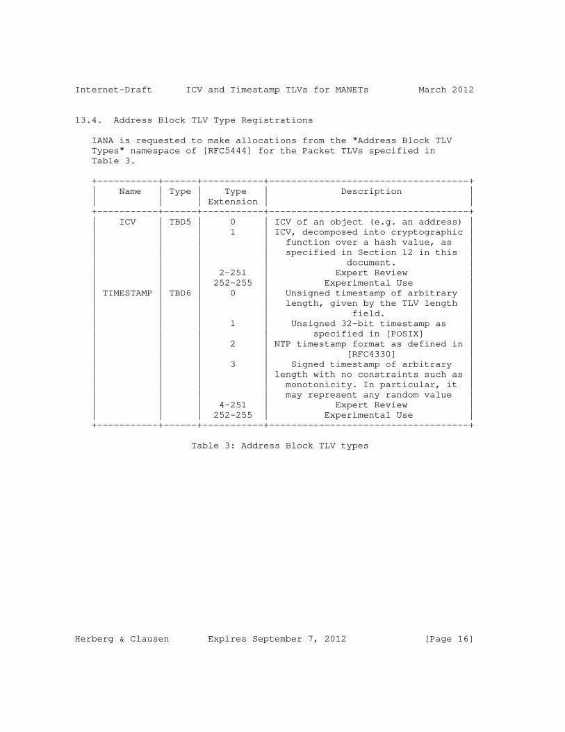
Internet-Draft ICV and Timestamp TLVs for MANETs March 2012
13.4. Address Block TLV Type Registrations
IANA is requested to make allocations from the "Address Block TLV Types" namespace of [RFC5444] for the Packet TLVs specified in Table 3.
+-----------+------+-----------+------------------------------------+ | Name | Type | Type | Description | | | | Extension | | +-----------+------+-----------+------------------------------------+ | ICV | TBD5 | 0 | ICV of an object (e.g. an address) | | | | 1 | ICV, decomposed into cryptographic | | | | | function over a hash value, as | | | | | specified in Section 12 in this | | | | | document. | | | | 2-251 | Expert Review | | | | 252-255 | Experimental Use | | TIMESTAMP | TBD6 | 0 | Unsigned timestamp of arbitrary | | | | | length, given by the TLV length | | | | | field. | | | | 1 | Unsigned 32-bit timestamp as | | | | | specified in [POSIX] | | | | 2 | NTP timestamp format as defined in | | | | | [RFC4330] | | | | 3 | Signed timestamp of arbitrary | | | | | length with no constraints such as | | | | | monotonicity. In particular, it | | | | | may represent any random value | | | | 4-251 | Expert Review | | | | 252-255 | Experimental Use | +-----------+------+-----------+------------------------------------+
Table 3: Address Block TLV types
Herberg & Clausen Expires September 7, 2012 [Page 16]

Internet-Draft ICV and Timestamp TLVs for MANETs March 2012
13.5. Hash Function
IANA is requested to create a new registry for hash functions that can be used when creating an ICV, as specified in Section 12 of this document. The initial assignments and allocation policies are specified in Table 4.
+-------------+-----------+-----------------------------------------+ | Hash | Algorithm | Description | | function | | | | value | | | +-------------+-----------+-----------------------------------------+ | 0 | none | The "identity function": the hash value | | | | of an object is the object itself | | 1 | SHA1 | [SHS] | | 2 | SHA224 | [SHS] | | 3 | SHA256 | [SHS] | | 4 | SHA384 | [SHS] | | 5 | SHA512 | [SHS] | | 6-251 | | Expert Review | | 252-255 | | Experimental Use | +-------------+-----------+-----------------------------------------+
Table 4: Hash-Function registry
13.6. Cryptographic Algorithm
IANA is requested to create a new registry for the cryptographic function, as specified in Section 12 of this document. Initial assignments and allocation policies are specified in Table 5.
+----------------+-----------+--------------------------------------+ | Cryptographic | Algorithm | Description | | function value | | | +----------------+-----------+--------------------------------------+ | 0 | none | The "identity function": the value | | | | of an encrypted hash is the hash | | | | itself | | 1 | RSA | [RFC3447] | | 2 | DSA | [DSA] | | 3 | HMAC | [RFC2104] | | 4 | 3DES | [3DES] | | 5 | AES | [AES] | | 6 | ECDSA | [ECDSA] | | 7-251 | | Expert Review | | 252-255 | | Experimental Use | +----------------+-----------+--------------------------------------+
Herberg & Clausen Expires September 7, 2012 [Page 17]

Internet-Draft ICV and Timestamp TLVs for MANETs March 2012
Table 5: Cryptographic function registry
14. Security Considerations
This document does not specify a protocol. It provides a syntactical component for cryptographic ICVs of messages and packets as defined in [RFC5444]. It can be used to address security issues of a MANET routing protocol or MANET routing protocol extension. As such, it has the same security considerations as [RFC5444].
In addition, a MANET routing protocol or MANET routing protocol extension that uses this specification MUST specify the usage as well as the security that is attained by the cryptographic ICVs of a message or a packet.
As an example, a MANET routing protocol that uses this component to reject "badly formed" or "insecure" messages if a control message does not contain a valid ICV, SHOULD indicate the security assumption that if the ICV is valid, the message is considered valid. It also SHOULD indicate the security issues that are counteracted by this measure (e.g. link or identity spoofing) as well as the issues that are not counteracted (e.g. compromised keys).
15. Acknowledgements
The authors would like to thank Bo Berry (Cisco), Alan Cullen (BAE), Justin Dean (NRL), Christopher Dearlove (BAE), Paul Lambert (Marvell), Jerome Milan (Ecole Polytechnique) and Henning Rogge (FGAN) for their constructive comments on the document.
The authors also appreciate the detailed reviews from the Area Directors, in particular Stewart Bryant (Cisco), Stephen Farrel (Trinity College Dublin), and Robert Sparks (Tekelec), as well as Donald Eastlake (Huawei) from the Security Directorate.
16. References
16.1. Normative References
[3DES] National Institute of Standards and Technology, "Recommendation for the Triple Data Encryption Algorithm (TDEA) Block Cipher", NIST Special Publication 800-67, May 2004.
[AES] National Institute of Standards & Technology,
Herberg & Clausen Expires September 7, 2012 [Page 18]
Internet-Draft ICV and Timestamp TLVs for MANETs March 2012
"Specification for the Advanced Encryption Standard (AES)", FIPS 197, November 2001.
[BCP26] Narten, T. and H. Alvestrand, "Guidelines for Writing an IANA Considerations Section in RFCs", RFC 5226, BCP 26, May 2008.
[DSA] National Institute of Standards & Technology, "Digital ICV Standard", NIST, FIPS PUB 186, May 1994.
[ECDSA] American National Standards Institute, "Public Key Cryptography for the Financial Services Industry: The Elliptic Curve Digital ICV Algorithm (ECDSA)", ANS X9.62- 2005, November 2005.
[POSIX] IEEE Computer Society, "1003.1-2008 Standard for Information Technology - Portable Operating System Interface (POSIX)", Base Specifications Issue 7, December 2008.
[RFC2104] Krawczyk, H., Bellare, M., and R. Canetti, "HMAC: Keyed- Hashing for Message Authentication", RFC 2104, February 1997.
[RFC2119] Bradner, S., "Key words for use in RFCs to Indicate Requirement Levels", RFC 2119, BCP 14, March 1997.
[RFC3447] Staddon, J. and B. Kaliski, "Public-Key Cryptography Standards (PKCS) #1: RSA Cryptography Specifications Version 2.1", RFC 3447, February 2003.
[RFC4330] Mills, D., "Simple Network Time Protocol (SNTP) Version 4 for IPv4, IPv6 and OSI", RFC 4330, January 2006.
[RFC5444] Clausen, T., Dearlove, C., Dean, J., and C. Adjih, "Generalized MANET Packet/Message Format", RFC 5444, February 2009.
[SHS] National Institute of Standards and Technology, "Secure Hash Standard", NIST FIPS 180-2, August 2002.
16.2. Informative References
[OLSRv2] Clausen, T., Dearlove, C., and P. Jacquet, "The Optimized Link State Routing Protocol version 2", work in progress draft-ietf-manet-olsrv2-13.txt, October 2011.
[RFC6130] Clausen, T., Dean, J., and C. Dearlove, "MANET
Herberg & Clausen Expires September 7, 2012 [Page 19]

Internet-Draft ICV and Timestamp TLVs for MANETs March 2012
Neighborhood Discovery Protocol (NHDP)", RFC 6130, March 2011.
Authors’ Addresses
Ulrich Herberg Fujitsu Laboratories of America 1240 E. Arques Ave. Sunnyvale, CA, 94085 USA
Email: [email protected] URI: http://www.herberg.name/
Thomas Heide Clausen LIX, Ecole Polytechnique 91128 Palaiseau Cedex, France
Phone: +33 6 6058 9349 Email: [email protected] URI: http://www.thomasclausen.org/
Herberg & Clausen Expires September 7, 2012 [Page 20]

Internet Engineering Task Force R. ColeInternet-Draft US Army CERDECIntended status: Experimental J. MackerExpires: August 3, 2012 Naval Research Laboratory A. Bierman Brocade January 31, 2012
Definition of Managed Objects for Performance Reporting draft-ietf-manet-report-mib-02
Abstract
This memo defines a portion of the Management Information Base (MIB) for use with network management protocols in the Internet community. In particular, it describes objects for configuring autonomous report generation on any device that supports MIBs containing counter and gauge objects for performance monitoring. This allows a management station to instruct a device to build off-line reports to be collected asynchronously by the management station. Further, this REPORT-SAMPLED-MIB can be configured in a proxy configuration where the report generation is performed on a device in close network proximity to the device containing the referenced counter objects. Hence, this capability allows network operators to reduce the SNMP polling traffic burden on Mobile Ad-Hoc and Disruption Tolerant Networks which is typical of SNMP performance management applications.
Status of This Memo
This Internet-Draft is submitted in full conformance with the provisions of BCP 78 and BCP 79.
Internet-Drafts are working documents of the Internet Engineering Task Force (IETF). Note that other groups may also distribute working documents as Internet-Drafts. The list of current Internet- Drafts is at http://datatracker.ietf.org/drafts/current/.
Internet-Drafts are draft documents valid for a maximum of six months and may be updated, replaced, or obsoleted by other documents at any time. It is inappropriate to use Internet-Drafts as reference material or to cite them other than as "work in progress."
This Internet-Draft will expire on August 3, 2012.
Copyright Notice
Cole, et al. Expires August 3, 2012 [Page 1]

Internet-Draft The REPORT-SAMPLED-MIB January 2012
Copyright (c) 2012 IETF Trust and the persons identified as the document authors. All rights reserved.
This document is subject to BCP 78 and the IETF Trust’s Legal Provisions Relating to IETF Documents (http://trustee.ietf.org/license-info) in effect on the date of publication of this document. Please review these documents carefully, as they describe your rights and restrictions with respect to this document. Code Components extracted from this document must include Simplified BSD License text as described in Section 4.e of the Trust Legal Provisions and are provided without warranty as described in the Simplified BSD License.
Table of Contents
1. Introduction . . . . . . . . . . . . . . . . . . . . . . . . . 3 2. The Internet-Standard Management Framework . . . . . . . . . . 3 3. Conventions . . . . . . . . . . . . . . . . . . . . . . . . . 4 4. Overview . . . . . . . . . . . . . . . . . . . . . . . . . . . 4 4.1. REPORT-SAMPLED-MIB Management Model . . . . . . . . . . . 4 4.2. Terms . . . . . . . . . . . . . . . . . . . . . . . . . . 6 5. Structure of the MIB Module . . . . . . . . . . . . . . . . . 6 5.1. Textual Conventions . . . . . . . . . . . . . . . . . . . 6 5.2. The Sampled Group . . . . . . . . . . . . . . . . . . . . 7 5.3. The Notifications Group . . . . . . . . . . . . . . . . . 7 6. Relationship to Other MIB Modules . . . . . . . . . . . . . . 7 6.1. Relationship to the SNMPv2-MIB . . . . . . . . . . . . . . 7 6.2. Relationship to the RMON2-MIB . . . . . . . . . . . . . . 8 6.3. MIB modules required for IMPORTS . . . . . . . . . . . . . 8 7. Definitions . . . . . . . . . . . . . . . . . . . . . . . . . 8 8. Security Considerations . . . . . . . . . . . . . . . . . . . 19 9. IANA Considerations . . . . . . . . . . . . . . . . . . . . . 22 10. Contributors . . . . . . . . . . . . . . . . . . . . . . . . . 22 11. Acknowledgements . . . . . . . . . . . . . . . . . . . . . . . 22 12. References . . . . . . . . . . . . . . . . . . . . . . . . . . 22 12.1. Normative References . . . . . . . . . . . . . . . . . . . 22 12.2. Informative References . . . . . . . . . . . . . . . . . . 23 Appendix A. Change Log . . . . . . . . . . . . . . . . . . . . . 23 Appendix B. Open Issues . . . . . . . . . . . . . . . . . . . . . 25 Appendix C. . . . . . . . . . . . . . . . . . . . . . . . . . . 26
Cole, et al. Expires August 3, 2012 [Page 2]
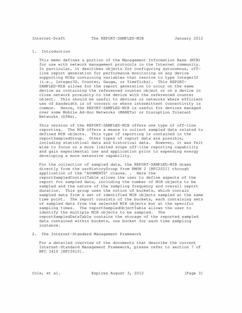
Internet-Draft The REPORT-SAMPLED-MIB January 2012
1. Introduction
This memo defines a portion of the Management Information Base (MIB) for use with network management protocols in the Internet community. In particular, it describes objects for configuring autonomous, off- line report generation for performance monitoring on any device supporting MIBs containing variables that resolve to type Integer32 (i.e., Integer32, Counter, Gauge, or TimeTicks). This REPORT- SAMPLED-MIB allows for the report generation to occur on the same device as containing the referenced counter object or on a device in close network proximity to the device with the referenced counter object. This should be useful to devices or networks where efficient use of bandwidth is of concern or where intermittent connectivity is common. Hence, the REPORT-SAMPLED-MIB is useful for devices managed over some Mobile Ad-Hoc Networks (MANETs) or Disruption Tolerant Networks (DTNs).
This version of the REPORT-SAMPLED-MIB offers one type of off-line reporting. The MIB offers a means to collect sampled data related to defined MIB objects. This type of reporting is contained in the reportSampledGroup. Other types of report data are possible, including statistical data and historical data. However, it was felt wise to focus on a more limited scope off-line reporting capability and gain experimental use and application prior to expending energy developing a more extensive capability.
For the collection of sampled data, the REPORT-SAMPLED-MIB draws directly from the usrHistoryGroup from RMON 2 [RFC2021] through application of the ’AUGMENTS’ clause. . Here the reportSampledControlTable allows the user to define aspects of the report for sampled data, including the number of MIB objects to be sampled and the nature of the sampling frequency and overall report duration. This group uses the notion of buckets, which contain sampled data from a set of identified MIB objects sampled at the same time point. The report consists of the buckets, each containing sets of sampled data from the selected MIB objects but at the specific sampling times. The reportSampledObjectTable allows the user to identify the multiple MIB objects to be sampled. The reportSampledDataTable contains the storage of the reported sampled data contained within buckets, one bucket for each time sampling instance.
2. The Internet-Standard Management Framework
For a detailed overview of the documents that describe the current Internet-Standard Management Framework, please refer to section 7 of RFC 3410 [RFC3410].
Cole, et al. Expires August 3, 2012 [Page 3]

Internet-Draft The REPORT-SAMPLED-MIB January 2012
Managed objects are accessed via a virtual information store, termed the Management Information Base or MIB. MIB objects are generally accessed through the Simple Network Management Protocol (SNMP). Objects in the MIB are defined using the mechanisms defined in the Structure of Management Information (SMI). This memo specifies a MIB module that is compliant to the SMIv2, which is described in STD 58, RFC 2578 [RFC2578], STD 58, RFC 2579 [RFC2579] and STD 58, RFC 2580 [RFC2580].
3. Conventions
The key words "MUST", "MUST NOT", "REQUIRED", "SHALL", "SHALL NOT", "SHOULD", "SHOULD NOT", "RECOMMENDED", "MAY", and "OPTIONAL" in this document are to be interpreted as described in RFC 2119 [RFC2119].
4. Overview
The REPORT-SAMPLED-MIB references performance objects in other MIBs (and in other devices) and generates off-line performance reports related to those referenced objects. The REPORT-SAMPLED-MIB can be coincident with the other MIB or can reside on another device in close network proximity to the device containing the referenced performance related object.
4.1. REPORT-SAMPLED-MIB Management Model
This section describes the management model for the REPORT-SAMPLED- MIB process.
Figure 1 illustrates a potential use of the REPORT-SAMPLED-MIB for the generation of off-line, remotely generated reports. The management station on the left hand side of the illustration instructs the remote device to create reports through manipulation of the ReportCntrl Objects in the REPORT-SAMPLED-MIB resident on the remote device. The reports instruct the device to monitor the status of specified counters (on other MIBs and potentially on other devices in close network proximity) periodically. The reports are stored locally until the management station decides to pull them off the device. The figure shows a case where the REPORT-SAMPLED-MIB generates a notification that Report_2 has completed, prompting the management station to pull Report_2 from the device.
Cole, et al. Expires August 3, 2012 [Page 4]

Internet-Draft The REPORT-SAMPLED-MIB January 2012
Mgmt Device Station REPORT-SAMPLED-MIB MIB_1 +---------+ +-----+ | | | | Build_Rep_1 |+-------+| +--+ | +----------------->||cntrl_1||<------>|PC| | |+-------+|<-+ +--+--+ | | | | | | MIB_2 | | | +-----+ | | | | | | | +--+ | | | +---->|PC| | Build_Rep_2 |+-------+| +-->+--+--+ +----------------->||cntrl_2||<---+ |+-------+| | | | | Build_Rep_3 |+-------+| +----------------->||cntrl_3||<---+ MIB_n |+-------+| | +-----+ | | | | | |+-----+ | | +--+ | ||Rep_1| | +-->|PC| | |+-----+ | +--+--+ | | |+-----+ | <------------------||Rep_2| | Notf_Rep_2 |+-----+ | | | |+-----+ | ||Rep_3| | |+-----+ | Get_Rep_2 | | +----------------->| | | | <-----------------+| | Send_Rep_2 +---------+
Figure 1: REPORT-SAMPLED-MIB front-end report generation process.
This version of the REPORT-SAMPLED-MIB provides for the collection of sampled data instead of statistical data. It does this by augmenting the usrHistory group from RMON2 [RFC2021] which allows for the generation of reports collecting the sampled object values binned for the purpose of aggregation and efficiency of collection. These are
Cole, et al. Expires August 3, 2012 [Page 5]

Internet-Draft The REPORT-SAMPLED-MIB January 2012
defined within the reportSampledGroup. The model used for this type of report generation is based upon three tables. The reportSampledControlTable defines aspects of the report generation related to duration of the reporting interval, the bin (or bucket) sizes for the report, and the number of object values collected for each bucket. The reportUsrHistoryObjectTable identifies the specific MIB objects whose values are binned within the report. And the reportSampledDataTable contains the binned data values collected for the report.
4.2. Terms
The following definitions apply throughout this document:
o Control - Objects defined within this document which set the parameters for specific reports to be generated offline on the the remote managed device.
o Data - Objects which hold the sampled report data.
5. Structure of the MIB Module
This section presents the structure of the REPORT-SAMPLED-MIB module. The objects are arranged into the following groups:
o reportSampledMIBNotifications - defines the notifications associated with the REPORT-SAMPLED-MIB.
o reportSampledMIBObjects - defines the objects forming the basis for the REPORT-SAMPLED-MIB. These objects are divided up by function into the following groups (currently only one group is defined):
o
* Sampled Group - This group contains the objects which support the generation (collection) of reports exposing sampled data values.
o reportSampledMIBConformance - Defines a variety of conformance of implementations of this REPORT-SAMPLED-MIB.
5.1. Textual Conventions
No textual conventions are used in the REPORT-SAMPLED-MIB.
Cole, et al. Expires August 3, 2012 [Page 6]

Internet-Draft The REPORT-SAMPLED-MIB January 2012
5.2. The Sampled Group
The Sampled Group contains tables which allows for the development of reports based upon sampling the referenced counter objects at specified intervals. The development of this group within the REPORT-SAMPLED-MIB which augments the User History group from the RMON 2 MIB [RFC2021]. The Sampled Group is composed of:
o reportSampledControlTable - allows for the setting of the parameters of the report.
o reportSampledObjectTable - sets the referenced objects to be sampled during the test. With this capability, the management application can reference multiple objects, all of which are sampled during the test and reported out through the reportSampledData Table.
o reportSampledDataTable - contains the reports.
5.3. The Notifications Group
The Notifications Sub-tree contains the list of notifications supported within the REPORT-SAMPLED-MIB and their intended purpose or utility. The single notification defined within this MIB module is the ’reportSampledNewDataReport’. This notification is sent by the agent upon completion of a given report on the device. The notification contains the following objects: ’usrHistoryControlOwner’, the entity that configured this report entry, and the ’reportSampledReportIndex’, the index of the data table for this report. Collectively, these objects allow the management application to pull the completed report from the agent.
6. Relationship to Other MIB Modules
The text of this section specifies the relationship of the MIB modules contained in this document to other standards, particularly to standards containing other MIB modules. Definitions imported from other MIB modules and other MIB modules that SHOULD be implemented in conjunction with the MIB module contained within this document are identified in this section.
6.1. Relationship to the SNMPv2-MIB
The ’system’ group in the SNMPv2-MIB [RFC3418] is defined as being mandatory for all systems, and the objects apply to the entity as a whole. The ’system’ group provides identification of the management entity and certain other system-wide data. The REPORT-SAMPLED-MIB does not duplicate those objects.
Cole, et al. Expires August 3, 2012 [Page 7]

Internet-Draft The REPORT-SAMPLED-MIB January 2012
6.2. Relationship to the RMON2-MIB
The REPORT-SAMPLED-MIB is closely related to the RMON2-MIB [RFC2021] usrHistoryGroup. Specifically, the reportSampledGroup is a direct copy of the RMON2 User History Group, with the names changed to comply with the naming conventions within the REPORT-SAMPLED-MIB. Further, the design and use of the control tables within the REPORT- SAMPLED-MIB draw exactly from the definition of these table structures in the earlier RMON MIBs through the use of the ’AUGMENTS’ clause within the ’reportSampledControlTable’ and the ’reportSampledTable’ in this MIB module.
6.3. MIB modules required for IMPORTS
Citations are not permitted within a MIB module, but any module mentioned in an IMPORTS clause or document mentioned in a REFERENCE clause is a Normative reference, and must be cited someplace within the narrative sections. Therefore, the imported items in this MIB module, such as Textual Conventions, that are not already cited, are cited in this section. Since relationships to other MIB modules should be described in the narrative text, this section will cite modules from which Textual Conventions are imported.
The REPORT-SAMPLED-MIB module IMPORTS objects from SNMPv2-SMI [RFC2578], SNMPv2-TC [RFC2579], SNMPv2-CONF [RFC2580], IF-MIB [RFC2863], and INET-ADDRESS-MIB [RFC4001]. Significantly, the REPORT-SAMPLED-MIB module also IMPORTS objects from the RMON2-MIB module [RFC2021].
7. Definitions
REPORT-SAMPLED-MIB DEFINITIONS ::= BEGIN
IMPORTS
MODULE-IDENTITY, OBJECT-TYPE, NOTIFICATION-TYPE, Gauge32, Integer32, experimental FROM SNMPv2-SMI -- [RFC2578]
TimeStamp FROM SNMPv2-TC -- [RFC2579]
MODULE-COMPLIANCE, OBJECT-GROUP, NOTIFICATION-GROUP FROM SNMPv2-CONF -- [RFC2580]
Cole, et al. Expires August 3, 2012 [Page 8]

Internet-Draft The REPORT-SAMPLED-MIB January 2012
usrHistoryControlEntry, usrHistoryObjectEntry, usrHistoryControlIndex, usrHistoryControlOwner, usrHistoryObjectIndex -- usrHistoryControlObjects, usrHistoryControlBucketsRequested, -- usrHistoryControlBucketsGranted, usrHistoryControlInterval, -- usrHistoryControlStatus, -- usrHistoryObjectVariable, usrHistoryObjectSampleType FROM RMON2-MIB -- [RFC2021]
InetAddress, InetAddressType FROM INET-ADDRESS-MIB -- [RFC4001] ;
reportSampledMIB MODULE-IDENTITY LAST-UPDATED "201201311300Z" -- January 31, 2012 ORGANIZATION "IETF MANET Working Group" CONTACT-INFO "WG E-Mail: [email protected]
WG Chairs: [email protected] [email protected]
Editors: Robert G. Cole US Army CERDEC 6010 Frankford Road Aberdeen Proving Ground, MD 21005 USA +1 443 395-8744 [email protected]
Joseph Macker Naval Research Laboratory Washington, D.C. 20375 USA [email protected]
Andy Bierman Brocade [email protected]" DESCRIPTION "This MIB module contains managed object definitions for the autonmous reporting of performance object counters. Copyright (C) The IETF Trust (2009). This version of this MIB module is part of RFC xxxx; see the RFC itself for full legal notices."
-- Revision History
Cole, et al. Expires August 3, 2012 [Page 9]

Internet-Draft The REPORT-SAMPLED-MIB January 2012
REVISION "201201311300Z" -- January 31, 2012 DESCRIPTION "The sixth draft of this MIB module published as draft-ietf-manet-report-mib-02.txt.
Revisions to this draft include a) Pulled the statistical and historical reporting from the MIB module and left only the sampled reporting, in order to greatly simplify the first instance of this reporting MIB module. b) Renamed the module, the REPORT-SAMPLED-MIB module. c) Leveraged the RMON2-MIB module more effectively through the use of the AUGMENTS clause. d) Changed the module to ’experimental’. " REVISION "201102171300Z" -- February 17, 2011 DESCRIPTION "The fifth draft of this MIB module published as draft-ietf-manet-report-mib-01.txt. This document has been promoted to a MANET Working Group draft.
Revisions to this draft include a) Proposed changes to the statsReport table to simplify communications between device and mgmt application, b) Added Notifications, c) Changed the reporting structure of the Sampled and the History reporting to align with the structure of the Statistics reports for the purpose of allowing for efficient notification and collection of data reports. d) Ran through smilint to clean up all errors and most warning. A few still remain. " REVISION "201007051300Z" -- July 05, 2010 DESCRIPTION "The fourth draft of this MIB module published as draft-ietf-manet-report-mib-00.txt. This document has been promoted to a MANET Working Group draft.
Significant revisions to this draft include a) added support for proxy configurations through the addition of address objects associated with the referenced counter objects associated with the
Cole, et al. Expires August 3, 2012 [Page 10]

Internet-Draft The REPORT-SAMPLED-MIB January 2012
performance reports." REVISION "201003021300Z" -- March 02, 2010 DESCRIPTION "The third draft of this MIB module published as draft-cole-manet-report-mib-02.txt. Significant revisions to this draft include a) changed naming of usrHistoryGroup to sampledGroup and b) added a historyGroup." REVISION "200910251300Z" -- October 25, 2009 DESCRIPTION "The second draft of this MIB module published as draft-cole-manet-report-mib-01.txt. Significant revisions to this draft include a) the inclusion of raw data collection borrow blatently from the usrHistory Group within RMON2, b) the deletion of the CurrentHistoryTable from version -00, c) modifications to the overall structure of the MIB, and d) the definition of various Compliance options for implementations related to this MIB." REVISION "200904281300Z" -- April 28, 2009 DESCRIPTION "Initial draft of this MIB module published as draft-cole-manet-report-mib-00.txt." -- RFC-Editor assigns XXXX ::= { experimental 998 } -- to be assigned by IANA
-- TEXTUAL CONVENTIONs -- None
-- -- Top-Level Object Identifier Assignments --
reportSampledMIBNotifications OBJECT IDENTIFIER ::= { reportSampledMIB 0 } reportSampledMIBObjects OBJECT IDENTIFIER ::= { reportSampledMIB 1 } reportSampledMIBConformance OBJECT IDENTIFIER ::= { reportSampledMIB 2 }
reportSampledGroup OBJECT IDENTIFIER ::= { reportSampledMIBObjects 1 }
-- Then, the reportSampledGroup assignments are :
Cole, et al. Expires August 3, 2012 [Page 11]

Internet-Draft The REPORT-SAMPLED-MIB January 2012
-- reportSampledControlTable - 1 -- reportSampledObjectTable - 2 -- reportSampledDataTable - 3
reportSampledControlTable OBJECT-TYPE SYNTAX SEQUENCE OF SampledControlEntry MAX-ACCESS not-accessible STATUS current DESCRIPTION "A list of data-collection configuration entries." ::= { reportSampledGroup 1 }
reportSampledControlEntry OBJECT-TYPE SYNTAX SampledControlEntry MAX-ACCESS not-accessible STATUS current DESCRIPTION "A list of parameters that set up a group of user-defined MIB objects to be sampled periodically (called a bucket-group).
For example, an instance of reportSampledControlInterval might be named reportSampledControlInterval.1" AUGMENTS { usrHistoryControlEntry } ::= { reportSampledControlTable 1 }
SampledControlEntry ::= SEQUENCE { reportSampledControlRequestedNumber Integer32, reportSampledControlReportNumber Integer32 }
reportSampledControlRequestedNumber OBJECT-TYPE SYNTAX Integer32 (1..127) MAX-ACCESS read-create STATUS current DESCRIPTION "The number of reports to be generated and stored by this agent for this report request.
This object may not be modified if the associated reportSampledControlStatus object is equal to active(1)." DEFVAL { 1 } ::= { reportSampledControlEntry 1 }
reportSampledControlReportNumber OBJECT-TYPE
Cole, et al. Expires August 3, 2012 [Page 12]

Internet-Draft The REPORT-SAMPLED-MIB January 2012
SYNTAX Integer32 (1..127) MAX-ACCESS read-only STATUS current DESCRIPTION "The number of the current report in progress. The first report is assigned a number equal to ’1’. Each successive report number is incremented by unity. When the last report is completed, this value is set to reportSampledControlRequestedNumber + 1." ::= { reportSampledControlEntry 2 }
-- Object table
reportSampledObjectTable OBJECT-TYPE SYNTAX SEQUENCE OF SampledObjectEntry MAX-ACCESS not-accessible STATUS current DESCRIPTION "A list of data-collection configuration entries." ::= { reportSampledGroup 2 }
reportSampledObjectEntry OBJECT-TYPE SYNTAX SampledObjectEntry MAX-ACCESS not-accessible STATUS current DESCRIPTION "A list of MIB instances to be sampled periodically.
Entries in this table are created when an associated reportSampledControlObjects object is created.
The usrHistoryControlIndex value in the index is that of the associated reportSampledControlEntry.
For example, an instance of reportSampledObjectVariable might be reportSampledObjectVariable.1.3" AUGMENTS { usrHistoryObjectEntry } ::= { reportSampledObjectTable 1 }
SampledObjectEntry ::= SEQUENCE { reportSampledObjectIpAddrType InetAddressType, reportSampledObjectIPAddress InetAddress }
reportSampledObjectIpAddrType OBJECT-TYPE SYNTAX InetAddressType MAX-ACCESS read-create
Cole, et al. Expires August 3, 2012 [Page 13]

Internet-Draft The REPORT-SAMPLED-MIB January 2012
STATUS current DESCRIPTION "This identifies the IP address type of the IP address associated with the secondary counter object to be monitored within this report.
This object may not be modified if the associated reportStatsControlStatus object is equal to active(1)." ::= { reportSampledObjectEntry 1 }
reportSampledObjectIPAddress OBJECT-TYPE SYNTAX InetAddress MAX-ACCESS read-create STATUS current DESCRIPTION "This identifies the IP addree of the secondary counter object to be monitored within this report.
This object may not be modified if the associated reportStatsControlStatus object is equal to active(1)." ::= { reportSampledObjectEntry 2 }
-- data table reportSampledTable OBJECT-TYPE SYNTAX SEQUENCE OF SampledEntry MAX-ACCESS not-accessible STATUS current DESCRIPTION "A list of user defined history entries." ::= { reportSampledGroup 3 }
reportSampledEntry OBJECT-TYPE SYNTAX SampledEntry MAX-ACCESS not-accessible STATUS current DESCRIPTION "A historical sample of user-defined variables. This sample is associated with the reportSampledControlEntry which set up the parameters for a regular collection of these samples.
The usrHistoryControlIndex value in the index identifies the reportSampledControlEntry on whose behalf this entry was created.
The usrHistoryObjectIndex value in the index identifies
Cole, et al. Expires August 3, 2012 [Page 14]

Internet-Draft The REPORT-SAMPLED-MIB January 2012
the reportSampledObjectEntry on whose behalf this entry was created.
For example, an instance of reportSampledAbsValue, which represents the 14th sample of a variable collected as specified by reportSampledControlEntry.1 and reportSampledObjectEntry.1.5, would be named reportSampledAbsValue.1.14.5" INDEX { usrHistoryControlIndex, reportSampledReportIndex, reportSampledSampleIndex, usrHistoryObjectIndex } ::= { reportSampledTable 1 }
SampledEntry ::= SEQUENCE { reportSampledReportIndex Integer32, reportSampledSampleIndex Integer32, reportSampledIntervalStart TimeStamp, reportSampledIntervalEnd TimeStamp, reportSampledAbsValue Gauge32, reportSampledValStatus INTEGER }
reportSampledReportIndex OBJECT-TYPE SYNTAX Integer32 (1..127) MAX-ACCESS read-only STATUS current DESCRIPTION "An index that uniquely identifies the particular report this entry is associated with among the set of reports requested through the reportSampledControlNumber in the reportSampledControlEntry. This index starts at 1 and increases by one as each new report is generated." ::= { reportSampledEntry 1 }
reportSampledSampleIndex OBJECT-TYPE SYNTAX Integer32 (1..2147483647) MAX-ACCESS not-accessible STATUS current DESCRIPTION "An index that uniquely identifies the particular sample this entry represents among all samples associated with the same reportSampledControlEntry. This index starts at 1 and increases by one as each new sample is taken." ::= { reportSampledEntry 2 }
reportSampledIntervalStart OBJECT-TYPE SYNTAX TimeStamp MAX-ACCESS read-only STATUS current
Cole, et al. Expires August 3, 2012 [Page 15]

Internet-Draft The REPORT-SAMPLED-MIB January 2012
DESCRIPTION "The value of sysUpTime at the start of the interval over which this sample was measured. If the probe keeps track of the time of day, it should start the first sample of the history at a time such that when the next hour of the day begins, a sample is started at that instant.
Note that following this rule may require the probe to delay collecting the first sample of the history, as each sample must be of the same interval. Also note that the sample which is currently being collected is not accessible in this table until the end of its interval." ::= { reportSampledEntry 3 }
reportSampledIntervalEnd OBJECT-TYPE SYNTAX TimeStamp MAX-ACCESS read-only STATUS current DESCRIPTION "The value of sysUpTime at the end of the interval over which this sample was measured." ::= { reportSampledEntry 4 }
reportSampledAbsValue OBJECT-TYPE SYNTAX Gauge32 MAX-ACCESS read-only STATUS current DESCRIPTION "The absolute value (i.e. unsigned value) of the user-specified statistic during the last sampling period. The value during the current sampling period is not made available until the period is completed.
To obtain the true value for this sampling interval, the associated instance of reportSampledValStatus must be checked, and reportSampledAbsValue adjusted as necessary.
If the MIB instance could not be accessed during the sampling interval, then this object will have a value of zero and the associated instance of reportSampledValStatus will be set to ’valueNotAvailable(1)’." ::= { reportSampledEntry 5 }
reportSampledValStatus OBJECT-TYPE SYNTAX INTEGER { valueNotAvailable(1), valuePositive(2),
Cole, et al. Expires August 3, 2012 [Page 16]

Internet-Draft The REPORT-SAMPLED-MIB January 2012
valueNegative(3) } MAX-ACCESS read-only STATUS current DESCRIPTION "This object indicates the validity and sign of the data in the associated instance of reportSampledAbsValue.
If the MIB instance could not be accessed during the sampling interval, then ’valueNotAvailable(1)’ will be returned.
If the sample is valid and actual value of the sample is greater than or equal to zero then ’valuePositive(2)’ is returned.
If the sample is valid and the actual value of the sample is less than zero, ’valueNegative(3)’ will be returned. The associated instance of reportSampledAbsValue should be multiplied by -1 to obtain the true sample value." ::= { reportSampledEntry 6 }
-- -- Notifications --
reportSampledNotificationObjects OBJECT IDENTIFIER ::= {reportSampledMIBNotifications 1}
-- reportSampledNotificationObjects
reportSampledNewDataReport NOTIFICATION-TYPE OBJECTS { usrHistoryControlOwner, -- The entity that -- configured this entry reportSampledReportIndex -- The index of the -- data table for this report } STATUS current DESCRIPTION "reportSampledNewDataReport is a notification sent when a new report is completed from the reportSampledControlTable. The notification carries the index from the control table that established this report and the index from the data table that holds this report. Indication of the new report is when the reportSampledControlReportNumber
Cole, et al. Expires August 3, 2012 [Page 17]

Internet-Draft The REPORT-SAMPLED-MIB January 2012
is incremented." ::= { reportSampledNotificationObjects 1 }
-- -- Compliance Statements --
-- Mandatory for Sampled will include all.
reportSampledCompliances OBJECT IDENTIFIER ::= { reportSampledMIBConformance 1 } reportSampledMIBGroups OBJECT IDENTIFIER ::= { reportSampledMIBConformance 2 }
reportSampledCompliance MODULE-COMPLIANCE STATUS current DESCRIPTION "The Sampled basic implementation requirements for managed network entities that implement the REPORT Sampled process." MODULE -- this module MANDATORY-GROUPS { reportSampledLocalGroup } ::= { reportSampledCompliances 1 }
reportSampledNotificationCompliance MODULE-COMPLIANCE STATUS current DESCRIPTION "The Sampled Notification implementation requirements for managed network entities that implement the REPORT process." MODULE -- this module MANDATORY-GROUPS { reportSampledNotificationObjectGroup } ::= { reportSampledCompliances 2 }
-- Units of Conformance
reportSampledLocalGroup OBJECT-GROUP OBJECTS { reportSampledControlRequestedNumber, reportSampledControlReportNumber, reportSampledObjectIpAddrType, reportSampledObjectIPAddress, reportSampledReportIndex, reportSampledIntervalStart, reportSampledIntervalEnd,
Cole, et al. Expires August 3, 2012 [Page 18]
Internet-Draft The REPORT-SAMPLED-MIB January 2012
reportSampledAbsValue, reportSampledValStatus } STATUS current DESCRIPTION "Set of REPORT state objects implemented in this module." ::= { reportSampledMIBGroups 1 }
--reportSampledImportedGroup OBJECT-GROUP -- OBJECTS { -- usrHistoryControlObjects, -- usrHistoryControlBucketsRequested, -- usrHistoryControlBucketsGranted, -- usrHistoryControlInterval, -- usrHistoryControlOwner, -- usrHistoryControlStatus, -- usrHistoryObjectVariable, -- usrHistoryObjectSampleType -- } -- STATUS current -- DESCRIPTION -- "Set of REPORT state objects implemented -- in this module." --::= { reportSampledMIBGroups 2 }
reportSampledNotificationObjectGroup NOTIFICATION-GROUP NOTIFICATIONS { reportSampledNewDataReport } STATUS current DESCRIPTION "Set of REPORT notifications implemented in this module for the Sampled reports." ::= { reportSampledMIBGroups 3 }
END
8. Security Considerations
This REPORT-SAMPLED-MIB defines a capability where the local device may poll other remote devices to collect performance data accessible through other MIB modules on the remote devices. These capabilities defined within the REPORT-SAMPLED-MIB are control-able by a network management application through SNMP. As such, a network management application could potentially use the REPORT-SAMPLED-MIB as a mechanism to implement a Distributed Denial-of-Service (DDoS) attack
Cole, et al. Expires August 3, 2012 [Page 19]

Internet-Draft The REPORT-SAMPLED-MIB January 2012
against remote devices. Care should be taken to secure access to the REPORT-SAMPLED-MIB agent. Specifically, access control mechanisms and authentication mechanisms (via SNMPv3) should always be used for SNMP SET operations. Further, some objects may contain data deemed sensitive and authentication and encryption mechanisms (via SNMPv3) should be used for SNMP GET operations.
There are a number of management objects defined in this MIB module with a MAX-ACCESS clause of read-write and/or read-create. Such objects may be considered sensitive or vulnerable in some network environments. The support for SET operations in a non-secure environment without proper protection can have a negative effect on network operations.
These are the tables and objects and their sensitivity/vulnerability:
o The reportSampledControlTable is a writable table whose columnar objects are read-create. The following objects with MAX ACCESS of read-create and their security sensitivities are:
o
* usrHistoryControlBucketRequested - this object identifies the requested number of buckets (or intervals) requested for each identified object for each report instance. As such, this related to the total device memory necessary to hold the collected data for the identified reports. The device must determine whether it has the necessary storage. If not, the device can indicate the available storage through the usrHistoryControlBucketGranted object within this table. The device to protect itself against memory overruns.
* usrHistoryControlInterval - this object identifies the time interval being sampling events. If set too low, the device may not be able to sample the object on remote devices fast enough to satisfy the requested interval. Further, setting this value too low could be used to overwhelm the processing capabilities of the remote agent, resulting in a Denial-of-Service (DoS) attack.
* reportSampledControlRequestedNumber - this object identifies the requested number of consecutive reports of this type to be generated and stored in this device. When, the value of this object should be considered in the local device’s estimates of memory consumption related to this control table row.
* usrHistoryControlOwner - this objects provides a name associated with the presumed identity of the application
Cole, et al. Expires August 3, 2012 [Page 20]

Internet-Draft The REPORT-SAMPLED-MIB January 2012
configuring this report. If the local device or management applications attribute any authority to the values contained in this object, then it is critical to secure access to setting or modifying the value of this object.
* usrHistoryControlStatus - this is the RowStatus object controlling the configuration of this table row.
o The reportSampledObjectTable is a writable table whose columnar objects are read-create. The following objects with MAX ACCESS of read-create and their security sensitivities are:
o
* usrHistoryObjectVariable - this object identifies the specific OID on a (potentially) remote agent whose counter or gauge values are to be collected for the reports. If, for whatever reason, the values of this OID collected within the report is deemed sensitive, then the SNMP GET operations issued to collect these values should use SNMPv3 authentication and encryption mechanisms to protect.
* reportSampledObjectIpAddrType - this object identifies the address type associated with the address of the agent whose OID data is being collected for the report.
* reportSampledObjectIpAddress - this object identifies the address associated with the address of the agent whose OID data is being collected for the report. If the address of the remote devices is deemed sensitive, then the SNMP SETs which write or the SNMP GET which collect this information should be protected using SNMPv3 authentication and encryption mechanisms.
* usrHistoryObjectSampleType - this object identifies the the way in which data values are to be stored within the reports.
SNMP versions prior to SNMPv3 did not include adequate security. Even if the network itself is secure (for example by using IPSec), even then, there is no control as to who on the secure network is allowed to access and GET/SET (read/change/create/delete) the objects in this MIB module.
It is RECOMMENDED that implementers consider the security features as provided by the SNMPv3 framework (see [RFC3410], section 8), including full support for the SNMPv3 cryptographic mechanisms (for authentication and privacy).
Cole, et al. Expires August 3, 2012 [Page 21]

Internet-Draft The REPORT-SAMPLED-MIB January 2012
Further, deployment of SNMP versions prior to SNMPv3 is NOT RECOMMENDED. Instead, it is RECOMMENDED to deploy SNMPv3 and to enable cryptographic security. It is then a customer/operator responsibility to ensure that the SNMP entity giving access to an instance of this MIB module is properly configured to give access to the objects only to those principals (users) that have legitimate rights to indeed GET or SET (change/create/delete) them.
9. IANA Considerations
The MIB module in this document uses the following IANA-assigned OBJECT IDENTIFIER values recorded in the SMI Numbers registry:
Descriptor OBJECT IDENTIFIER value ---------- -----------------------
reportSampledMIB { experimental XXX }
10. Contributors
This MIB document uses the template authored by D. Harrington which is based on contributions from the MIB Doctors, especially Juergen Schoenwaelder, Dave Perkins, C.M.Heard and Randy Presuhn.
11. Acknowledgements
We would like to thank Bert Wijnen for pointing out the existence of the usrHistory group within RMON2 and in answering our numerous questions on the usrHistory group. Further, we wish to thank U. Herberg for promoting additions to this MIB through his thoughtful consideration of performance monitoring requirements for other MIBs within the MANET WG, e.g., NHDP and OLSR MIBs.
12. References
12.1. Normative References
[RFC2863] McCloghrie, K. and F. Kastenholz, "The Interfaces Group MIB", RFC 2863, June 2000.
[RFC3418] Presuhn, R., "Management Information Base (MIB) for the Simple Network Management Protocol (SNMP)", STD 62, RFC 3418, December 2002.
[RFC2119] Bradner, S., "Key words for use in RFCs to Indicate Requirement Levels", BCP 14, RFC 2119, March 1997.
Cole, et al. Expires August 3, 2012 [Page 22]

Internet-Draft The REPORT-SAMPLED-MIB January 2012
[RFC2578] McCloghrie, K., Ed., Perkins, D., Ed., and J. Schoenwaelder, Ed., "Structure of Management Information Version 2 (SMIv2)", STD 58, RFC 2578, April 1999.
[RFC2579] McCloghrie, K., Ed., Perkins, D., Ed., and J. Schoenwaelder, Ed., "Textual Conventions for SMIv2", STD 58, RFC 2579, April 1999.
[RFC2580] McCloghrie, K., Perkins, D., and J. Schoenwaelder, "Conformance Statements for SMIv2", STD 58, RFC 2580, April 1999.
[RFC4001] Daniele, M., Haberman, B., Routhier, S., and J. Schoenwaelder, "Textual Conventions for Internet Network Addresses", RFC 4001, February 2005.
12.2. Informative References
[RFC3410] Case, J., Mundy, R., Partain, D., and B. Stewart, "Introduction and Applicability Statements for Internet- Standard Management Framework", RFC 3410, December 2002.
[RFC2021] Waldbusser, S., "Remote Network Monitoring Management Information Base Version 2 using SMIv2", RFC 2021, January 1997.
Appendix A. Change Log
Changes from draft-ietf-manet-report-mib-01 to draft-ietf-manet-report-mib-02 draft.
1. Stripped the Statistical and the Historical Reports from this draft in order to greatly simplify the initial development and experiments of this MIB module.
2. Changed the RFC category to Experimental.
3. Completed the Security section.
4. Relied upon the AUGMENTS statement to simplify further this MIB definition.
Changes from draft-ietf-manet-report-mib-00 to draft-ietf-manet-report-mib-01 draft.
1. Proposed additions to the statsReports in order to potentially simplify data transmission to management applications.
Cole, et al. Expires August 3, 2012 [Page 23]

Internet-Draft The REPORT-SAMPLED-MIB January 2012
2. Added some Notification definitions and their relationship to the three reports’ structure, i.e., statsReports, sampledReports, and historyReports.
3. In the process of adding notifications for the Sampled and the History reports, decided to restructure the reports from their previously rolling storage model to the fixed interval reporting used all along in the Statistics reporting. This allows the agent to notify the management application that a report has completed and that it is ready to be pulled from the agent storage.
4. Ran MIB through smilint checker and cleaned up all errors and most warnings. A few warnings remain to be addressed.
5. Cleaned up textual material.
Changes from draft-cole-manet-report-mib-02 to draft-ietf-manet-report-mib-00 draft.
1. Major change was the incorporation of the IP address objects associated with all objects of type ’OBJECT IDENTIFIER’. This allows the REPORT-SAMPLED-MIB to exist as a proxy report generation capability on a device separate but in close proximity to the device monitoring the referenced object.
2. Cleaned up the up front text, reducing the repetition with the object descriptions in the MIB.
3. Worked on and added sections discussing the relationship to other MIBs.
Changes from draft-cole-manet-report-mib-01 to draft-cole-manet-report-mib-02 draft.
1. Restructured the MIB somewhat to now offer the three reporting capabilities in increasing order of detail: a) statistical reports, b) sampled reports, and c) historical reports.
2. Renamed the usrHistoryGroup and elements to samplingGroup. This is in line with its actual capabilities.
3. Added a new historyGroup which provides a history of change events.
4. Updated the4 Conformance section to reflect the above changes and additions. But did not yet run smilint to check MIB syntax.
Cole, et al. Expires August 3, 2012 [Page 24]

Internet-Draft The REPORT-SAMPLED-MIB January 2012
Changes from draft-cole-manet-report-mib-00 to draft-cole-manet-report-mib-01 draft.
1. Added (copied) the usrHistory group from RMON2 into the REPORT- SAMPLED-MIB.
2. Restructured the MIB to account for the inclusion of the reportSampledGroup.
3. Dropped the reportCurReportsTable as this did not make sense within the context of the REPORT-SAMPLED-MIB.
4. Added the Compliance and Conformance material. Defined several Compliance Groups to all for base implementations of the REPORT- SAMPLED-MIB for only statistical reports, for only historical reports or for both. Allow for enhanced implementations to address higher capacity issues and extension to metric reporting for statistical reporting.
5. Ran the MIB through the smilint checker and in the process corrected numerous typos, omissions, TEXTUAL CONVENTIONS, IMPORTS, etc.
6. Updated main text to reflect changes.
Appendix B. Open Issues
This section contains the set of open issues related to the development and design of the REPORT-SAMPLED-MIB. This section will not be present in the final version of the MIB and will be removed once all the open issues have been resolved.
1. Identify all objects requiring non-volatile storage in their DESCRIPTION clauses.
Cole, et al. Expires August 3, 2012 [Page 25]

Internet-Draft The REPORT-SAMPLED-MIB January 2012
Appendix C.
*************************************************************** * Note to the RFC Editor (to be removed prior to publication) * * * * 1) The reference to RFCXXXX within the DESCRIPTION clauses * * of the MIB module point to this draft and are to be * * assigned by the RFC Editor. * * * * 2) The reference to RFCXXX2 throughout this document point * * to the current draft-ietf-manet-report-xx.txt. This * * need to be replaced with the XXX RFC number. * * * ***************************************************************
Authors’ Addresses
Robert G. Cole US Army CERDEC 6010 Frankford Road Aberdeen Proving Ground, Maryland 21005 USA
Phone: +1 443 395 8744 EMail: [email protected] URI: http://www.cs.jhu.edu/˜rgcole/
Joseph Macker Naval Research Laboratory Washington, D.C. 20375 USA
EMail: [email protected]
Andy Bierman Brocade
EMail: [email protected]
Cole, et al. Expires August 3, 2012 [Page 26]


Network Working Group J. Macker, editorInternet-Draft NRLIntended status: Experimental March 6, 2012Expires: September 7, 2012
Simplified Multicast Forwarding draft-ietf-manet-smf-14
Abstract
This document describes a Simplified Multicast Forwarding (SMF) mechanism that provides basic Internet Protocol (IP) multicast forwarding suitable for limited wireless mesh and mobile ad hoc network (MANET) use. It is mainly applicable in situations where efficient flooding represents an acceptable engineering design trade- off. It defines techniques for multicast duplicate packet detection (DPD), to be applied in the forwarding process, for both IPv4 and IPv6 protocol use. This document also specifies optional mechanisms for using reduced relay sets to achieve more efficient multicast data distribution within a mesh topology as compared to classic flooding. Interactions with other protocols, such as use of information provided by concurrently running unicast routing protocols, or interaction with other multicast protocols, as well as multiple deployment approaches are also described. Distributed algorithms for selecting reduced relay sets and related discussion are provided in the appendices. Basic issues relating to the operation of multicast MANET border routers are discussed, but ongoing work remains in this area, and is beyond the scope of this document.
Status of this Memo
This Internet-Draft is submitted in full conformance with the provisions of BCP 78 and BCP 79.
Internet-Drafts are working documents of the Internet Engineering Task Force (IETF). Note that other groups may also distribute working documents as Internet-Drafts. The list of current Internet- Drafts is at http://datatracker.ietf.org/drafts/current/.
Internet-Drafts are draft documents valid for a maximum of six months and may be updated, replaced, or obsoleted by other documents at any time. It is inappropriate to use Internet-Drafts as reference material or to cite them other than as "work in progress."
This Internet-Draft will expire on September 7, 2012.
Copyright Notice
Macker, editor Expires September 7, 2012 [Page 1]

Internet-Draft SMF March 2012
Copyright (c) 2012 IETF Trust and the persons identified as the document authors. All rights reserved.
This document is subject to BCP 78 and the IETF Trust’s Legal Provisions Relating to IETF Documents (http://trustee.ietf.org/license-info) in effect on the date of publication of this document. Please review these documents carefully, as they describe your rights and restrictions with respect to this document. Code Components extracted from this document must include Simplified BSD License text as described in Section 4.e of the Trust Legal Provisions and are provided without warranty as described in the Simplified BSD License.
This document may contain material from IETF Documents or IETF Contributions published or made publicly available before November 10, 2008. The person(s) controlling the copyright in some of this material may not have granted the IETF Trust the right to allow modifications of such material outside the IETF Standards Process. Without obtaining an adequate license from the person(s) controlling the copyright in such materials, this document may not be modified outside the IETF Standards Process, and derivative works of it may not be created outside the IETF Standards Process, except to format it for publication as an RFC or to translate it into languages other than English.
Macker, editor Expires September 7, 2012 [Page 2]

Internet-Draft SMF March 2012
Table of Contents
1. Introduction and Scope . . . . . . . . . . . . . . . . . . . . 5 2. Terminology . . . . . . . . . . . . . . . . . . . . . . . . . 5 3. Applicability Statement . . . . . . . . . . . . . . . . . . . 6 4. Overview and Functioning . . . . . . . . . . . . . . . . . . . 7 5. SMF Packet Processing and Forwarding . . . . . . . . . . . . . 9 6. SMF Duplicate Packet Detection . . . . . . . . . . . . . . . . 11 6.1. IPv6 Duplicate Packet Detection . . . . . . . . . . . . . 12 6.1.1. IPv6 SMF_DPD Header Option . . . . . . . . . . . . . . 12 6.1.2. IPv6 Identification-based DPD . . . . . . . . . . . . 15 6.1.3. IPv6 Hash-based DPD . . . . . . . . . . . . . . . . . 17 6.2. IPv4 Duplicate Packet Detection . . . . . . . . . . . . . 18 6.2.1. IPv4 Identification-based DPD . . . . . . . . . . . . 18 6.2.2. IPv4 Hash-based DPD . . . . . . . . . . . . . . . . . 20 7. Relay Set Selection . . . . . . . . . . . . . . . . . . . . . 20 7.1. Non-Reduced Relay Set Forwarding . . . . . . . . . . . . . 21 7.2. Reduced Relay Set Forwarding . . . . . . . . . . . . . . . 21 8. SMF Neighborhood Discovery Requirements . . . . . . . . . . . 23 8.1. SMF Relay Algorithm TLV Types . . . . . . . . . . . . . . 24 8.1.1. SMF Message TLV Type . . . . . . . . . . . . . . . . . 24 8.1.2. SMF Address Block TLV Type . . . . . . . . . . . . . . 26 9. SMF Border Gateway Considerations . . . . . . . . . . . . . . 26 9.1. Forwarded Multicast Groups . . . . . . . . . . . . . . . . 27 9.2. Multicast Group Scoping . . . . . . . . . . . . . . . . . 28 9.3. Interface with Exterior Multicast Routing Protocols . . . 28 9.4. Multiple Border Routers . . . . . . . . . . . . . . . . . 29 10. Security Considerations . . . . . . . . . . . . . . . . . . . 30 11. IANA Considerations . . . . . . . . . . . . . . . . . . . . . 32 11.1. IPv6 SMF_DPD Header Extension Option Type . . . . . . . . 32 11.2. TaggerId Types (TidTy) . . . . . . . . . . . . . . . . . . 33 11.3. Well-known Multicast Address . . . . . . . . . . . . . . . 34 11.4. SMF Type-Length-Values . . . . . . . . . . . . . . . . . . 34 11.4.1. Expert Review for created Type Extension Registries . 34 11.4.2. SMF Message TLV Type (SMF_TYPE) . . . . . . . . . . . 34 11.4.3. SMF Address Block TLV Type (SMF_NBR_TYPE) . . . . . . 35 11.4.4. SMF Relay Algorithm ID Registry . . . . . . . . . . . 35 12. Acknowledgments . . . . . . . . . . . . . . . . . . . . . . . 36 13. References . . . . . . . . . . . . . . . . . . . . . . . . . . 36 13.1. Normative References . . . . . . . . . . . . . . . . . . . 36 13.2. Informative References . . . . . . . . . . . . . . . . . . 38 Appendix A. Essential Connecting Dominating Set (E-CDS) Algorithm . . . . . . . . . . . . . . . . . . . . . . 39 A.1. E-CDS Relay Set Selection Overview . . . . . . . . . . . . 39 A.2. E-CDS Forwarding Rules . . . . . . . . . . . . . . . . . . 40 A.3. E-CDS Neighborhood Discovery Requirements . . . . . . . . 41 A.4. E-CDS Selection Algorithm . . . . . . . . . . . . . . . . 43 Appendix B. Source-based Multipoint Relay (S-MPR) . . . . . . . . 45
Macker, editor Expires September 7, 2012 [Page 3]

Internet-Draft SMF March 2012
B.1. S-MPR Relay Set Selection Overview . . . . . . . . . . . . 45 B.2. S-MPR Forwarding Rules . . . . . . . . . . . . . . . . . . 46 B.3. S-MPR Neighborhood Discovery Requirements . . . . . . . . 47 B.4. S-MPR Selection Algorithm . . . . . . . . . . . . . . . . 49 Appendix C. Multipoint Relay Connected Dominating Set (MPR-CDS) Algorithm . . . . . . . . . . . . . . . . . 50 C.1. MPR-CDS Relay Set Selection Overview . . . . . . . . . . . 50 C.2. MPR-CDS Forwarding Rules . . . . . . . . . . . . . . . . . 51 C.3. MPR-CDS Neighborhood Discovery Requirements . . . . . . . 52 C.4. MPR-CDS Selection Algorithm . . . . . . . . . . . . . . . 52 Author’s Address . . . . . . . . . . . . . . . . . . . . . . . . . 53
Macker, editor Expires September 7, 2012 [Page 4]

Internet-Draft SMF March 2012
1. Introduction and Scope
Unicast routing protocols, designed for MANET and wireless mesh use, often apply distributed algorithms to flood routing control plane messages within a MANET routing domain. For example, algorithms specified within [RFC3626] and [RFC3684] provide distributed methods of dynamically electing reduced relay sets that attempt to efficiently flood routing control messages while maintaining a connected set under dynamic topological conditions.
Simplified Multicast Forwarding (SMF) extends the efficient flooding concept to the data forwarding plane, providing an appropriate multicast forwarding capability for use cases where localized, efficient flooding is considered an effective design approach. The baseline design is intended to provide a basic, best effort multicast forwarding capability that is constrained to operate within a single MANET routing domain.
An SMF routing domain is an instance of an SMF routing protocol with common policies, under a single network administration authority. The main design goals of this document are to:
o adapt efficient relay sets in MANET environments [RFC2501]; o define the needed IPv4 and IPv6 multicast duplicate packet detection (DPD) mechanisms to support multi-hop, packet forwarding.
2. Terminology
The key words "MUST", "MUST NOT", "REQUIRED", "SHALL", "SHALL NOT", "SHOULD", "SHOULD NOT", "RECOMMENDED", "NOT RECOMMENDED", "MAY", and "OPTIONAL" in this document are to be interpreted as described in [RFC2119].
The terms introduced in [RFC5444], including "packet", "message", "TLV Block", "TLV", and "address" are to be interpreted as described therein.
The following abbreviations are used throughout this document:
Macker, editor Expires September 7, 2012 [Page 5]

Internet-Draft SMF March 2012
+--------------+----------------------------------------------------+ | Abbreviation | Definition | +--------------+----------------------------------------------------+ | MANET | Mobile Ad hoc Network | | SMF | Simplified Multicast Forwarding | | CF | Classic Flooding | | CDS | Connected Dominating Set | | MPR | Multi-Point Relay | | S-MPR | Source-based MPR | | MPR-CDS | MPR-based CDS | | E-CDS | Essential CDS | | NHDP | Neighborhood Discovery Protocol | | DPD | Duplicate Packet Detection | | I-DPD | Identification-based DPD | | H-DPD | Hash-based DPD | | HAV | Hash-assist Value | | FIB | Forwarding Information Base | | TLV | type-length-value encoding | | DoS | Denial of Service | | SMF Router | A MANET Router, implementing the protocol | | | specified in this document | | SMF Routing | A MANET Routing Domain wherein the protocol, | | Domain | specified in this document, is operating | +--------------+----------------------------------------------------+
3. Applicability Statement
Within dynamic wireless routing topologies, maintaining traditional forwarding trees to support a multicast routing protocol is often not as effective as in wired networks due to the reduced reliability and increased dynamics of mesh topologies [MGL04] [GM99]. A basic packet forwarding service reaching all connected routers running the SMF protocol within a MANET routing domain may provide a useful group communication paradigm for various classes of applications, for example multimedia streaming, interactive group-based messaging and applications, peer-to-peer middleware multicasting, and multi-hop mobile discovery or registration services. SMF is likely only appropriate for deployment in limited dynamic MANET routing domains so that the flooding process can be contained, further defined as administratively scoped multicast forwarding domains in Section 9.2.
A design goal is that hosts may also participate in multicast traffic transmission and reception with standard IP network layer semantics (e.g., special or unnecessary encapsulation of IP packets should be avoided in this case). SMF deployments are able to connect and interoperate with existing standard multicast protocols operating within more conventional Internet infrastructures. To this end, a
Macker, editor Expires September 7, 2012 [Page 6]

Internet-Draft SMF March 2012
multicast border router or proxy mechanism MUST be used when deployed alongside more fixed-infrastructure IP multicast routing such Protocol Independent Multicast (PIM) variants [RFC3973] and [RFC4601]. Experimental SMF implementations and deployments have demonstrated gateway functionality at MANET border routers operating with existing external IP multicast routing protocols [CDHM07], [DHS08],and [DHG09]. SMF may be extended or combined with other mechanisms to provide increased reliability and group specific filtering; the details for this are out of scope for this document.
This document does not presently support forwarding of packets with directed broadcast addresses as a destination [RFC2644].
4. Overview and Functioning
Figure 1 provides an overview of the logical SMF router architecture, consisting of "Neighborhood Discovery", "Relay Set Selection" and "Forwarding Process" components. Typically, relay set selection (or self-election) occurs based on dynamic input from a neighborhood discovery process. SMF supports the case where neighborhood discovery and/or relay set selection information is obtained from a coexistent process (e.g., a lower layer mechanism or a unicast routing protocol using relay sets). In some algorithm designs, the forwarding decision for a packet can also depend on previous hop or incoming interface information. The asterisks (*) in Figure 1 mark the primitives and relationships, needed by relay set algorithms requiring previous-hop packet forwarding knowledge. ______________ _____________ | | | | | Neighborhood | | Relay Set | | Discovery |------------->| Selection | | | neighbor | Algorithm | |______________| info |_____________| \ / \ / neighbor\ /forwarding info* \ ____________ / status \ | | / ‘-->| Forwarding |<--’ | Process | ˜˜˜˜˜˜˜˜˜˜˜˜˜˜˜˜˜>|____________|˜˜˜˜˜˜˜˜˜˜˜˜˜˜˜˜˜> incoming packet, forwarded packets interface id*, and previous hop*
Figure 1: SMF router Architecture
Macker, editor Expires September 7, 2012 [Page 7]

Internet-Draft SMF March 2012
Certain IP multicast packets, defined in Section 9.2 and Section 5, are "non-forwardable". These multicast packets MUST be ignored by the SMF forwarding engine. The SMF forwarding engine MAY also work with policies and management interfaces to allow additional filtering control over which multicast packets are considered for potential SMF forwarding. This interface would allow more refined dynamic forwarding control once such techniques are matured for MANET operation. At present, further discussion of dynamic control is left to future work.
Interoperable SMF implementations MUST use compatible DPD approaches and be able to process the header options defined in this document for IPv6 operation.
Classic Flooding (CF) is defined as the simplest case of SMF multicast forwarding. With CF, all SMF routers forward each received multicast packet exactly once. In this case, the need for any relay set selection or neighborhood topology information is eliminated, at the expense of additional network overhead incurring from unnecessary packet retransmissions. With CF, the SMF DPD functionality is still required. While SMF supports CF as a mode of operation, the use of more efficient relay set modes is RECOMMENDED in order to reduce contention and congestion caused by unnecessary packet retransmissions [NTSC99].
An efficient, reduced relay set is constructed by selecting and updating, as needed, a subset of all possible routers in a MANET routing domain to act as SMF forwarders. Known distributed relay set selection algorithms have demonstrated the ability to provide and maintain a dynamic connected set for forwarding multicast IP packets [MDC04]. A few such relay set selection algorithms are described in the Appendices of this document and the basic designs borrow directly from previously documented IETF work. SMF relay set configuration is extensible and additional relay set algorithms beyond those specified here can be accommodated in future work.
Determining and maintaining an optimized set of relays generally requires dynamic neighborhood topology information. Neighborhood topology discovery functions MAY be provided by a MANET unicast routing protocol or by using the MANET NeighborHood Discovery Protocol (NHDP) [RFC6130], operating concurrently with SMF. This specification also allows alternative lower layer interfaces (e.g., radio router interface) to provide the necessary neighborhood information to aid in supporting more effective relay set election. An SMF implementation SHOULD provide the ability for multicast forwarding state to be dynamically managed per operating network interface. The relay state maintenance options and interactions are outlined in Section 7. This document states specific requirements
Macker, editor Expires September 7, 2012 [Page 8]

Internet-Draft SMF March 2012
for neighborhood discovery with respect to the forwarding process and the relay set selection algorithms described herein. For determining dynamic relay sets in the absence of other control protocols, SMF relies on NHDP to assist in IP layer 2-hop neighborhood discovery and maintenance for relay set election. "SMF_TYPE" and "SMF_NBR_TYPE" Message and Address Block TLV structures (per [RFC5444]) are defined by this document for use with NHDP to carry SMF-specific information. It is RECOMMENDED that all routers performing SMF operation in conjunction with NHDP include these TLV types in any NHDP HELLO messages generated. This capability allows for routers participating in SMF to be explicitly identified along with their respective dynamic relay set algorithm configuration.
5. SMF Packet Processing and Forwarding
The SMF Packet Processing and Forwarding actions are conducted with the following packet handling activities:
1. Processing of outbound, locally-generated multicast packets. 2. Reception and processing of inbound packets on specific network interfaces.
The purpose of intercepting outbound, locally-generated multicast packets is to apply any added packet marking needed to satisfy the DPD requirements so that proper forwarding may be conducted. Note that for some system configurations the interception of outbound packets for this purpose is not necessary.
Inbound multicast packets are received by the SMF implementation and processed for possible forwarding. SMF implementations MUST be capable of forwarding IP multicast packets with destination addresses that are not router-local and link-local for IPv6, as defined in [RFC4291], and that are not within the local network control block as defined by [RFC5771].
This will support generic multi-hop multicast application needs or distribute designated multicast traffic ingressing the SMF routing domain via border routers. The multicast addresses to be forwarded should be maintained by an a priori list or a dynamic forwarding information base (FIB) that MAY interact with future MANET dynamic group membership extensions or management functions.
The SL-MANET-ROUTERS multicast group is defined to contain all routers within an SMF routing domain, so that packets transmitted to the multicast address associated with the group will be attempted delivered to all connected routers running SMF. Due to the mobile nature of a MANET, routers running SMF may not be topologically
Macker, editor Expires September 7, 2012 [Page 9]

Internet-Draft SMF March 2012
connected at particular times. For IPv6, SL-MANET-ROUTERS is specified to be "site-local". Minimally, SMF MUST forward, as instructed by the relay set selection algorithm, unique (non- duplicate) packets received for SL-MANET-ROUTERS when the TTL/ hop-limit or hop limit value in the IP header is greater than 1. SMF MUST forward all additional global scope multicast addresses specified within the dynamic FIB or configured list as well. In all cases, the following rules MUST be observed for SMF multicast forwarding:
1. Any IP packets not addressed to an IP multicast address MUST NOT be forwarded by the SMF forwarding engine 2. IP multicast packets with TTL/hop-limit <= 1 MUST NOT be forwarded. 3. Link local IP multicast packets MUST NOT be forwarded. 4. Incoming IP multicast packets with an IP source address matching one of those of the local SMF router interface(s) MUST NOT be forwarded. 5. Received frames with the MAC source address matching any MAC address of the router’s interfaces MUST NOT be forwarded. 6. Received packets for which SMF cannot reasonably ensure temporal DPD uniqueness MUST NOT be forwarded. 7. Prior to being forwarded, the TTL/hop-limit of the forwarded packet MUST be decremented by one.
Note that rule #4 is important because over some types of wireless interfaces, the originating SMF router may receive re-transmissions of its own packets when they are forwarded by adjacent routers. This rule avoids unnecessary retransmission of locally-generated packets even when other forwarding decision rules would apply.
An additional processing rule also needs to be considered based upon a potential security threat. As discussed in Section 10, there is a potential DoS attack that can be conducted by remotely "previewing" (e.g., via a directional receive antenna) packets that an SMF router would be forwarding and conduct a "pre-play" attack by transmitting the packet before the SMF router would otherwise receive it but with a reduced TTL/hop-limit field value. This form of attack can cause an SMF router to create a DPD entry that would block the proper forwarding of the valid packet (with correct TTL/hop-limit) through the SMF routing domain. A RECOMMENDED approach to prevent this attack, when it is a concern, would be to cache temporal packet TTL/ hop-limit values along with the per-packet DPD state (hash value(s) and/or identifier as described in Section 6). Then, if a subsequent matching (with respect to DPD) packet arrives with a larger TTL/ hop-limit value than the packet that was previously forwarded, SMF should forward the new packet and update the TTL/hop-limit value cached with corresponding DPD state to the new, larger TTL/hop-limit
Macker, editor Expires September 7, 2012 [Page 10]

Internet-Draft SMF March 2012
value. There may be temporal cases where SMF would unnecessarily forward some duplicate packets using this approach, but those cases are expected to be minimal and acceptable when compared with the potential threat of denied service.
Once the SMF multicast forwarding rules have been applied, an SMF implementation MUST make a forwarding decision dependent upon the relay set selection algorithm in use. If the SMF implementation is using Classic Flooding (CF), the forwarding decision is implicit once DPD uniqueness is determined. Otherwise, a forwarding decision depends upon the current interface-specific relay set state. The descriptions of the relay set selection algorithms in the Appendices to this document specify the respective heuristics for multicast packet forwarding and specific DPD or other processing required to achieve correct SMF behavior in each case. For example, one class of forwarding is based upon relay set election status and the packet’s previous hop, while other classes designate the local SMF router as a forwarder for all neighboring routers.
6. SMF Duplicate Packet Detection
Duplicate packet detection (DPD) is often a requirement in MANET or wireless mesh packet forwarding mechanisms because packets may be transmitted out via the same physical interface as the one over which they were received. Routers may also receive multiple copies of the same packets from different neighbors or interfaces. SMF operation requires DPD and implementations MUST provide mechanisms to detect and reduce the likelihood of forwarding duplicate multicast packets using temporal packet identification. It is RECOMMENDED this be implemented by keeping a history of recently-processed multicast packets for comparison with incoming packets. A DPD packet cache history SHOULD be kept long enough so as to span the maximum network traversal lifetime, MAX_PACKET_LIFETIME, of multicast packets being forwarded within an SMF routing domain. The DPD mechanism SHOULD avoid keeping unnecessary state for packet flows such as those that are locally-generated or link-local destinations that would not be considered for forwarding, as presented in Section 5.
For IPv4 and IPv6, both, this document describes two basic multicast duplicate packet detection mechanisms: header content identification- based (I-DPD) and hash-based (H-DPD) duplicate detection. I-DPD is a mechanism using specific packet headers, and option headers in the case of IPv6, in combination with flow state to estimate the temporal uniqueness of a packet. H-DPD uses hashing over header fields and payload of a multicast packet, in order to provide an estimation of temporal uniqueness.
Macker, editor Expires September 7, 2012 [Page 11]

Internet-Draft SMF March 2012
Trade-offs of the two approaches to DPD merit different considerations dependent upon the specific SMF deployment scenario.
Because of the potential addition of a hop-by-hop option header with IPv6, all SMF routers in the same SMF deployments MUST be configured so as to use a common mechanism and DPD algorithm. The main difference between IPv4 and IPv6 SMF DPD specification is the avoidance of any additional header options for IPv4.
For each network interface, SMF implementations MUST maintain DPD packet state as needed to support the forwarding heuristics of the relay set algorithm used. In general, this involves keeping track of previously forwarded packets so that duplicates are not forwarded, but some relay techniques have additional considerations, such as discussed in Appendix B.2.
Additional details of I-DPD and H-DPD processing and maintenance for different classes of packets are described in the following.
6.1. IPv6 Duplicate Packet Detection
This section describes the mechanisms and options for SMF IPv6 DPD. The base IPv6 packet header does not provide any explicit packet identification header field that can be exploited for I-DPD. The following options are therefore described, to support IPv6 DPD: 1. a hop-by-hop SMF_DPD option header, defined in this document (Section 6.1.1), 2. the use of IPv6 fragment header fields for I-DPD, if one is present (Section 6.1.2), 3. the use of IPsec sequencing for I-DPD when a non-fragmented, IPsec header is detected (Section 6.1.2), and 4. an H-DPD approach assisted, as needed, by the SMF_DPD option header (Section 6.1.3).
SMF MUST provide a DPD marking module that can insert the hop-by-hop IPv6 header option, defined Section 6.1.1. This module MUST be invoked after any source-based fragmentation that may occur with IPv6, so as to ensure that all fragments are suitably marked. SMF IPv6 DPD is presently specified to allow either a packet hash or header identification method for DPD. An SMF implementation MUST be configured to operate either in H-DPD or I-DPD mode, and perform the corresponding tasks, outlined in Section 6.1.1 and Section 6.1.3.
6.1.1. IPv6 SMF_DPD Header Option
This section defines an IPv6 Hop-by-Hop Option [RFC2460], SMF_DPD, to serve the purpose of unique packet identification for IPv6 I-DPD. Additionally, the SMF_DPD header option provides a mechanism to
Macker, editor Expires September 7, 2012 [Page 12]

Internet-Draft SMF March 2012
guarantee non-collision of hash values for different packets when H-DPD is used.
If this is the only hop-by-hop option present, the optional "TaggerId" field (see below) is not included, and the size of the DPD packet identifier (sequence number) or hash token is 24 bits or less, this will result in the addition of 8 bytes to the IPv6 packet header including the "Next Header", "Header Extension Length", SMF_DPD option fields, and padding.
0 1 2 3 0 1 2 3 4 5 6 7 8 9 0 1 2 3 4 5 6 7 8 9 0 1 2 3 4 5 6 7 8 9 0 1 +-+-+-+-+-+-+-+-+-+-+-+-+-+-+-+-+-+-+-+-+-+-+-+-+-+-+-+-+-+-+-+-+ ... |0|0|0| SMF_DPD | Opt. Data Len | +-+-+-+-+-+-+-+-+-+-+-+-+-+-+-+-+-+-+-+-+-+-+-+-+-+-+-+-+-+-+-+-+ |H| DPD Identifier Option Fields or Hash Assist Value ... +-+-+-+-+-+-+-+-+-+-+-+-+-+-+-+-+-+-+-+-+-+-+-+-+-+-+-+-+-+-+-+-+
IPv6 SMF_DPD Hop-by-Hop Header Option
"Option Type" = (Lower 5 bits pending IANA assignment, highest order MUST be 000). By having these three bits be zero, this specification requires that routers not recognizing this option type should skip over this option and continue processing the header and that the option must not change en route [RFC2460].
"Opt. Data Len" = Length of option content (I.e., 1 + (<IdType> ? (<IdLen> + 1): 0) + Length(DPD ID)).
"H-bit" = a hash indicator bit value identifying DPD marking type. 0 == sequence-based approach with optional TaggerId and a tuple-based sequence number. 1 == indicates a hash assist value (HAV) field follows to aid in avoiding hash-based DPD collisions.
When the "H-bit" is cleared (zero value), the SMF_DPD format to support I-DPD operation is specified as shown in Figure 2 and defines the extension header in accordance with [RFC2460].
Macker, editor Expires September 7, 2012 [Page 13]

Internet-Draft SMF March 2012
0 1 2 3 0 1 2 3 4 5 6 7 8 9 0 1 2 3 4 5 6 7 8 9 0 1 2 3 4 5 6 7 8 9 0 1 +-+-+-+-+-+-+-+-+-+-+-+-+-+-+-+-+-+-+-+-+-+-+-+-+-+-+-+-+-+-+-+-+ ... |0|0|0| OptType | Opt. Data Len | +-+-+-+-+-+-+-+-+-+-+-+-+-+-+-+-+-+-+-+-+-+-+-+-+-+-+-+-+-+-+-+-+ |0|TidTy| TidLen| TaggerId (optional) ... | +-+-+-+-+-+-+-+-+ +-+-+-+-+-+-+-+-+-+-+-+-+-+-+-+-+ | | Identifier ... +-+-+-+-+-+-+-+-+-+-+-+-+-+-+-+-+-+-+-+-+-+-+-+-+-+-+-+-+-+-+-+-+
Figure 2: IPv6 SMF_DPD Header Option in I-DPD mode
"TidTy" = a 3-bit field indicating the presence and type of the optional "TaggerId" field. "TidLen" = a 4-bit field indicating the length (in octets) of the following TaggerId field. "TaggerId" = a field, is used to differentiate multiple ingressing border gateways that may commonly apply the SMF_DPD option header to packets from a particular source. Table 1 lists the TaggerId types, used in this document:
+---------+---------------------------------------------------------+ | Name | Purpose | +---------+---------------------------------------------------------+ | NULL | Indicates no "TaggerId" field is present. "TidLen" | | | MUST also be set to ZERO. | | DEFAULT | A "TaggerId" of non-specific context is present. | | | "TidLen + 1" defines the length of the TaggerId field | | | in bytes. | | IPv4 | A "TaggerId" representing an IPv4 address is present. | | | The "TidLen" MUST be set to 3. | | IPv6 | A "TaggerId" representing an IPv6 address is present. | | | The "TidLen" MUST be set to 15. | +---------+---------------------------------------------------------+
Table 1: TaggerId Types
This format allows a quick check of the "TidTy" field to determine if a "TaggerId" field is present. If "TidTy" is NULL, then the length of the DPD packet <Identifier> field corresponds to (<Opt. Data Len> - 1). If the <TidTy> is non-NULL, then the length of the "TaggerId" field is equal to (<TidLen> - 1) and the remainder of the option data comprises the DPD packet <Identifier> field. When the "TaggerId" field is present, the <Identifier> field can be considered a unique packet identifier in the context of the <TaggerId:srcAddr:dstAddr> tuple. When the "TaggerId" field is not present, then it is assumed the source applied the SMF_DPD option and the <Identifier> can be considered unique in the context of the IPv6 packet header <srcAddr: dstAddr> tuple. IPv6 I-DPD operation details are described in
Macker, editor Expires September 7, 2012 [Page 14]

Internet-Draft SMF March 2012
Section 6.1.2.
When the "H-bit" in the SMF_DPD option data is set, the data content value is interpreted as a Hash-Assist Value (HAV) used to facilitate H-DPD operation. In this case, the source or ingressing gateways apply the SMF_DPD with an HAV only when required to differentiate the hash value of a new packet with respect to hash values in the DPD cache. This situation can be detected locally on the router by running the hash algorithm and checking the DPD cache, prior to ingressing a previously unmarked packet or a locally sourced packet. This helps to guarantee the uniqueness of generated hash values when H-DPD is used. Additionally, this also avoids the added overhead of applying the SMF_DPD option header to every packet. For many hash algorithms, it is expected that only sparse use of the SMF_DPD option may be required. The format of the SMF_DPD header option for H-DPD operation is given in Figure 3.
0 1 2 3 0 1 2 3 4 5 6 7 8 9 0 1 2 3 4 5 6 7 8 9 0 1 2 3 4 5 6 7 8 9 0 1 +-+-+-+-+-+-+-+-+-+-+-+-+-+-+-+-+-+-+-+-+-+-+-+-+-+-+-+-+-+-+-+-+ ... |0|0|0| OptType | Opt. Data Len | +-+-+-+-+-+-+-+-+-+-+-+-+-+-+-+-+-+-+-+-+-+-+-+-+-+-+-+-+-+-+-+-+ |1| Hash Assist Value (HAV) ... +-+-+-+-+-+-+-+-+-+-+-+-+-+-+-+-+-+-+-+-+-+-+-+-+-+-+-+-+-+-+-+-+
Figure 3: IPv6 SMF_DPD Header Option in H-DPD Mode
The SMF_DPD option should be applied with an HAV to produce a unique hash digest for packets within the context of the IPv6 packet header <srcAddr>. The size of the HAV field is implied by the "Opt. Data Len". The appropriate size of the field depends upon the collision properties of the specific hash algorithm used. More details on IPv6 H-DPD operation are provided in Section 6.1.3.
6.1.2. IPv6 Identification-based DPD
Table 2 summarizes the IPv6 I-DPD processing and forwarding decision approach. Within the table ’*’ indicates an ignore field condition.
Macker, editor Expires September 7, 2012 [Page 15]

Internet-Draft SMF March 2012
+-------------+-----------+-----------+-----------------------------+ | IPv6 | IPv6 | IPv6 | SMF IPv6 I-DPD Mode Action | | Fragment | IPsec | I-DPD | | | Header | Header | Header | | +-------------+-----------+-----------+-----------------------------+ | Present | * | Not | Use Fragment Header I-DPD | | | | Present | Check and Process for | | | | | Forwarding | | Not Present | Present | Not | Use IPsec Header I-DPD | | | | Present | Check and Process for | | | | | Forwarding | | Present | * | Present | Invalid, do not Forward | | Not Present | Present | Present | Invalid, do not Forward | | Not Present | Not | Not | Add I-DPD Header,and | | | Present | Present | Process for Forwarding | | Not Present | Not | Present | Use I-DPD Header Check and | | | Present | | Process for Forwarding | +-------------+-----------+-----------+-----------------------------+
Table 2: IPv6 I-DPD Processing Rules
1. If a received IPv6 multicast packet is an IPv6 fragment, SMF MUST use the fragment extension header fields for packet identification. This identifier can be considered unique in the context of the <srcAddr:dstAddr> of the IP packet. 2. If the packet is an unfragmented IPv6 IPsec packet, SMF MUST use IPsec fields for packet identification. The IPsec header <sequence> field can be considered a unique identifier in the context of the <IPsecType:srcAddr:dstAddr:SPI> where the "IPsecType" is either AH or ESP [RFC4302]. 3. For unfragmented, non-IPsec, IPv6 packets, the use of the SMF_DPD header option is necessary to support I-DPD operation. The SMF_DPD header option is applied in the context of the <srcAddr> of the IP packet. hosts or ingressing SMF gateways are responsible for applying this option to support DPD. Table 3 summarizes these packet identification types:
+-----------+---------------------------------+---------------------+ | IPv6 | Packet DPD ID Context | Packet DPD ID | | Packet | | | | Type | | | +-----------+---------------------------------+---------------------+ | Fragment | <srcAddr:dstAddr> | <fragmentOffset:id> | | IPsec | <IPsecType:srcAddr:dstAddr:SPI> | <sequence> | | Packet | | | | Regular | <[TaggerId:]srcAddr:dstAddr> | <SMF_DPD option | | Packet | | header id> | +-----------+---------------------------------+---------------------+
Macker, editor Expires September 7, 2012 [Page 16]

Internet-Draft SMF March 2012
Table 3: IPv6 I-DPD Packet Identification Types
"IPsecType" is either Authentication Header (AH) or Encapsulating Security Payload (ESP).
The "TaggerId" is an optional field of the IPv6 SMF_DPD header option.
6.1.3. IPv6 Hash-based DPD
A default hash-based DPD approach (H-DPD) for use by SMF is specified as follows. An SHA-1 [RFC3174] hash of the non-mutable header fields, options fields, and data content of the IPv6 multicast packet is used to produce a 160-bit digest. The approach for calculating this hash value SHOULD follow the same guidelines described for calculating the Integrity Check Value (ICV) described in [RFC4302] with respect to non-mutable fields. This approach should have a reasonably low probability of digest collision when packet headers and content are varying. SHA-1 is being applied in SMF only to provide a low probability of collision and is not being used for cryptographic or authentication purposes. A history of the packet hash values SHOULD be maintained within the context of the IPv6 packet header <srcAddr>. SMF ingress points (i.e., source hosts or gateways) use this history to confirm that new packets are unique with respect to their hash value. The Hash-assist Value (HAV) field described in Section 6.1.1 is provided as a differentiating field when a digest collision would otherwise occur. Note that the HAV is an immutable option field and SMF MUST process any included HAV values (see Section 6.1.1) in its hash calculation.
If a packet results in a digest collision (i.e., by checking the H-DPD digest history) within the DPD cache kept by SMF forwarders, the packet SHOULD be silently dropped. If a digest collision is detected at an SMF ingress point the H-DPD option header is constructed with a randomly generated HAV. A HAV is recalculated as needed to produce a non-colliding hash value prior to forwarding. The multicast packet is then forwarded with the added IPv6 SMF_DPD header option. A common hash approach MUST be used by SMF routers for the applied HAV to consistently avoid hash collision and thus inadvertent packet drops.
The SHA-1 indexing and IPv6 HAV approaches are specified at present for consistency and robustness to suit experimental uses. Future approaches and experimentation may discover design tradeoffs in hash robustness and efficiency worth considering. Enhancements MAY include reducing the maximum payload length that is processed, determining shorter indexes, or applying more efficient hashing algorithms. Use of the HAV functionality may allow for application
Macker, editor Expires September 7, 2012 [Page 17]

Internet-Draft SMF March 2012
of "lighter-weight" hashing techniques that might not have been initially considered due to poor collision properties otherwise. Such techniques could reduce packet processing overhead and memory requirements.
6.2. IPv4 Duplicate Packet Detection
This section describes the mechanisms and options for IPv4 DPD. The following areas are described to support IPv4 DPD:
1. the use of IPv4 fragment header fields for I-DPD when they exist (Section 6.2.1), 2. the use of IPsec sequencing for I-DPD when a non-fragmented IPv4 IPsec packet is detected (Section 6.2.1), and 3. an H-DPD approach(Section 6.2.2) when neither of the above cases can be applied.
Although the IPv4 datagram has a 16-bit Identification (ID) field as specified in [RFC0791], it cannot be relied upon for DPD purposes due to common computer operating system implementation practices and the reasons described in the updated specification of the IPv4 ID Field [I-D.ietf-intarea-ipv4-id-update]. An SMF IPv4 DPD marking option like the IPv6 SMF_DPD option header is not specified since IPv4 header options are not as tractable for hosts as they are for IPv6. However, when IPsec is applied or IPv4 packets have been fragmented, the I-DPD approach can be applied reliably using the corresponding packet identifier fields described in Section 6.2.1 below. For the general IPv4 case (non-IPsec and non-fragmented packets), the H-DPD approach of Section 6.2.2 is RECOMMENDED.
Since IPv4 SMF does not specify an option header, the interoperability constraints are looser than the IPv6 version and forwarders may be operate with mixed H-DPD and I-DPD modes as long as they consistently perform the appropriate DPD routines outlined in the following sections. However, it is RECOMMENDED that a deployment be configured with a common mode for operational consistency.
6.2.1. IPv4 Identification-based DPD
Table 4 summarizes the IPv4 I-DPD processing approach once a packet has passed the basic forwardable criteria described in Section 5. To summarize, for IPv4, I-DPD is applicable only for packets which have been fragmented or have IPsec applied. Within the table ’*’ indicates an ignore field condition. DF, MF, Fragment offset correspond to related fields and flags defined in [RFC0791].
Macker, editor Expires September 7, 2012 [Page 18]

Internet-Draft SMF March 2012
+------+------+----------+---------+--------------------------------+ | DF | MF | Fragment | IPsec | IPv4 I-DPD Action | | flag | flag | offset | | | +------+------+----------+---------+--------------------------------+ | 1 | 1 | * | * | Invalid, Do Not Forward | | 1 | 0 | nonzero | * | Invalid, Do Not Forward | | * | 0 | zero | not | Use H-DPD check instead | | | | | Present | | | * | 0 | zero | Present | IPsec enhanced Tuple I-DPD | | | | | | Check and Process for | | | | | | Forwarding | | 0 | 0 | nonzero | * | Extended Fragment Offset Tuple | | | | | | I-DPD Check and Process for | | | | | | Forwarding | | 0 | 1 | zero or | * | Extended Fragment Offset Tuple | | | | nonzero | | I-DPD Check and Process for | | | | | | Forwarding | +------+------+----------+---------+--------------------------------+
Table 4: IPv4 I-DPD Processing Rules
For performance reasons, IPv4 network fragmentation and reassembly of multicast packets within wireless MANET networks should be minimized, yet SMF provides the forwarding of fragments when they occur. If the IPv4 multicast packet is a fragment, SMF MUST use the fragmentation header fields for packet identification. This identification can be considered temporally unique in the context of the <protocol:srcAddr: dstAddr> of the IPv4 packet. If the packet is an unfragmented IPv4 IPsec packet, SMF MUST use IPsec fields for packet identification. The IPsec header <sequence> field can be considered a unique identifier in the context of the <IPsecType:srcAddr:dstAddr:SPI> where the "IPsecType" is either AH or ESP [RFC4302]. Table 5 summarizes these packet identification types:
+-----------+---------------------------------+---------------------+ | IPv4 | Packet Identification Context | Packet Identifier | | Packet | | | | Type | | | +-----------+---------------------------------+---------------------+ | Fragment | <protocol:srcAddr:dstAddr> | <fragmentOffset:id> | | IPsec | <IPsecType:srcAddr:dstAddr:SPI> | <sequence> | | Packet | | | +-----------+---------------------------------+---------------------+
Table 5: IPv4 I-DPD Packet Identification Types
"IPsecType" is either Authentication Header (AH) or Encapsulating Security Payload (ESP).
Macker, editor Expires September 7, 2012 [Page 19]
Internet-Draft SMF March 2012
6.2.2. IPv4 Hash-based DPD
The hashing technique here is similar to that specified for IPv6 in Section 6.1.3, but the H-DPD header option with HAV is not considered. To ensure consistent IPv4 H-DPD operation among SMF routers, a default hashing approach is specified. A common DPD hashing algorithm for an SMF routing area is RECOMMENDED because colliding hash values for different packets result in a "false positive" duplicate packet detection and valid packets may be dropped with a small probability based on the hashing technique used. Since the "hash assist value" approach is not available for IPv4, use of a common hashing approach minimizes the hash collision packet drop probability over multiple hops of forwarding.
SMF MUST perform an SHA-1 [RFC3174] hash of the immutable header fields, option fields and data content of the IPv4 multicast packet resulting in a 160-bit digest. The approach for calculating the hash value SHOULD follow the same guidelines described for calculating the Integrity Check Value (ICV) described in [RFC4302] with respect to non-mutable fields. A history of the packet hash values SHOULD be maintained in the context of <protocol:srcAddr:dstAddr>. The context for IPv4 is more specific than that of IPv6 since the SMF_DPD HAV cannot be employed to mitigate hash collisions. A RECOMMENDED implementation detail for IPv4 H-DPD is to concatenate the 16-bit IPv4 ID value with the computed hash value as an extended DPD hash value that may provide reduced hash collisions in the cases where the IPv4 ID field is being set by host operating systems or gateways. When this approach is taken, the use of the supplemental "internal hash" technique as described in Section 10 is RECOMMENDED as a security measure.
The SHA-1 hash is specified at present for consistency and robustness. Future approaches and experimentation may discover design tradeoffs in hash robustness and efficiency worth considering for future revisions of SMF. This MAY include reducing the packet payload length that is processed, determining shorter indexes, or applying a more efficient hashing algorithm.
7. Relay Set Selection
SMF is flexible in its support of different reduced relay set mechanism for efficient flooding, the constraints imposed hereon being detailed in this section.
Macker, editor Expires September 7, 2012 [Page 20]
Internet-Draft SMF March 2012
7.1. Non-Reduced Relay Set Forwarding
SMF implementations MUST support CF as a basic forwarding mechanism when reduced relay set information is not available or not selected for operation. In CF mode, each router transmits a packet once that has passed the SMF forwarding rules. The DPD techniques described in Section 6 are critical to proper operation and prevent duplicate packet retransmissions by the same relays.
7.2. Reduced Relay Set Forwarding
MANET reduced relay sets are often achieved by distributed algorithms that can dynamically calculate a topological connected dominating set (CDS).
A goal of SMF is to apply reduced relay sets for more efficient multicast dissemination within dynamic topologies. To accomplish this an SMF implementation MUST support the ability to modify its multicast packet forwarding rules based upon relay set state received dynamically during operation. In this way, SMF operates effectively as neighbor adjacencies or multicast forwarding policies within the topology change.
In early SMF experimental prototyping, the relay set information has been derived from coexistent unicast routing control plane traffic flooding processes [MDC04]. From this experience, extra pruning considerations were sometimes required when utilizing a relay set from a separate routing protocol process. As an example, relay sets formed for the unicast control plane flooding MAY include additional redundancy that may not be desired for multicast forwarding use (e.g., biconnected relay set).
Here is a recommended criteria list for SMF relay set selection algorithm candidates:
1. Robustness to topological dynamics and mobility 2. Localized election or coordination of any relay sets 3. Reasonable minimization of CDS relay set size given above constraints 4. Heuristic support for preference or election metrics
Some relay set algorithms meeting these criteria are described in the Appendices of this document. Additional relay set selection algorithms may be specified in separate specifications in the future. Each Appendix subsection in this document can serve as a template for specifying additional relay algorithms.
Figure 4 depicts an information flow diagram of possible relay set
Macker, editor Expires September 7, 2012 [Page 21]
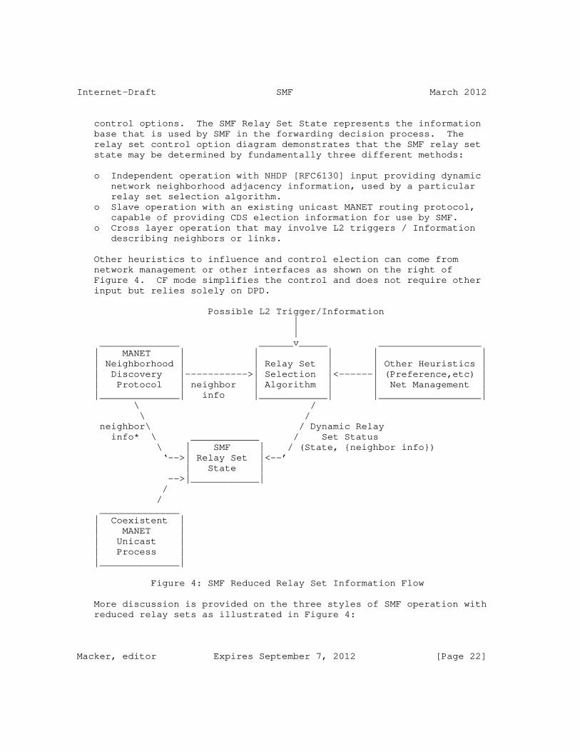
Internet-Draft SMF March 2012
control options. The SMF Relay Set State represents the information base that is used by SMF in the forwarding decision process. The relay set control option diagram demonstrates that the SMF relay set state may be determined by fundamentally three different methods:
o Independent operation with NHDP [RFC6130] input providing dynamic network neighborhood adjacency information, used by a particular relay set selection algorithm. o Slave operation with an existing unicast MANET routing protocol, capable of providing CDS election information for use by SMF. o Cross layer operation that may involve L2 triggers / Information describing neighbors or links.
Other heuristics to influence and control election can come from network management or other interfaces as shown on the right of Figure 4. CF mode simplifies the control and does not require other input but relies solely on DPD.
Possible L2 Trigger/Information | | ______________ ______v_____ __________________ | MANET | | | | | | Neighborhood | | Relay Set | | Other Heuristics | | Discovery |----------->| Selection |<------| (Preference,etc) | | Protocol | neighbor | Algorithm | | Net Management | |______________| info |____________| |__________________| \ / \ / neighbor\ / Dynamic Relay info* \ ____________ / Set Status \ | SMF | / (State, {neighbor info}) ‘-->| Relay Set |<--’ | State | -->|____________| / / ______________ | Coexistent | | MANET | | Unicast | | Process | |______________|
Figure 4: SMF Reduced Relay Set Information Flow
More discussion is provided on the three styles of SMF operation with reduced relay sets as illustrated in Figure 4:
Macker, editor Expires September 7, 2012 [Page 22]

Internet-Draft SMF March 2012
1. Independent operation: In this case, SMF operates independently from any unicast routing protocols. To support reduced relay sets SMF MUST perform its own relay set selection using information gathered from signaling. It is RECOMMENDED that an associated NHDP process be used for this signaling. NHDP messaging SHOULD be appended with additional [RFC5444] type- length-value (TLV) content to support SMF-specific requirements as discussed in [RFC6130] and for the applicable relay set algorithm described in the Appendices of this document or future specifications. Unicast routing protocols may co-exist, even using the same NHDP process, but signaling that supports reduced relay set selection for SMF is independent of these protocols. 2. Operation with CDS-aware unicast routing protocol: In this case, a coexistent unicast routing protocol provides dynamic relay set state based upon its own control plane CDS or neighborhood discovery information. 3. Cross-layer Operation: In this case, SMF operates using neighborhood status and triggers from a cross-layer information base for dynamic relay set selection and maintenance (e.g., lower link layer).
8. SMF Neighborhood Discovery Requirements
This section defines the requirements for use of the MANET Neighborhood Discovery Protocol (NHDP) [RFC6130] to support SMF operation. Note that basic CF forwarding requires no neighborhood topology knowledge since in this configured mode every SMF router relays all traffic. Supporting more reduced SMF relay set operation requires the discovery and maintenance of dynamic neighborhood topology information. NHDP can be used to provide this necessary information, however there are SMF-specific requirements for NHDP use. This is the case for both "independent" SMF operation where NHDP is being used specifically to support SMF or when one NHDP instance is used, both, for SMF and a coexistent MANET unicast routing protocol.
NHDP HELLO messages and the resultant neighborhood information base are described separately within the NHDP specification. To summarize, NHDP provides the following basic functions:
1. 1-hop neighbor link sensing and bidirectionality checks of neighbor links, 2. 2-hop neighborhood discovery including collection of 2-hop neighbors and connectivity information, 3. Collection and maintenance of the above information across multiple interfaces, and
Macker, editor Expires September 7, 2012 [Page 23]

Internet-Draft SMF March 2012
4. A method for signaling SMF information throughout the 2-hop neighborhood through the use of TLV extensions.
Appendices (A-C) of this document describe CDS-based relay set selection algorithms that can achieve efficient SMF operation, even in dynamic, mobile networks and each of the algorithms has been initially experimented within a working SMF prototype [MDDA07]. When using these algorithms in conjunction with NHDP, a method verifying neighbor SMF operation is required in order to insure correct relay set selection. NHDP along with SMF operation verification provides the necessary information required by these algorithms to conduct relay set selection. Verification of SMF operation may be done administratively or through the use of the SMF relay algorithms TLVs defined in the following subsections. Use of the SMF relay algorithm TLVs is RECOMMENDED when using NHDP for SMF neighborhood discovery.
Section 8.1 specifies SMF-specific TLV types, supporting general SMF operation or supporting the algorithms described in the Appendices. The Appendices describing several relay set algorithms also specify any additional requirements for use with NHDP and reference the applicable TLV types as needed.
8.1. SMF Relay Algorithm TLV Types
This section specifies TLV types to be used within NHDP messages to identify the CDS relay set selection algorithm(s) in use. Two TLV types are defined, one Message TLV type and one Address Block TLV type.
8.1.1. SMF Message TLV Type
The Message TLV type denoted SMF_TYPE is used to identify the existence of an SMF instance operating in conjunction with NHDP. This Message TLV type makes use of the extended type field as defined by [RFC5444] to convey the CDS relay set selection algorithm currently in use by the SMF message originator. When NHDP is used to support SMF operation, the SMF_TYPE TLV, containing the extended type field with the appropriate value, SHOULD be included in NHDP_HELLO messages (HELLO messages as defined in [RFC6130]). This allows SMF routers to learn when neighbors are configured to use NHDP for information exchange including algorithm type and related algorithm information. This information can be used to take action, such as ignoring neighbor information using incompatible algorithms. It is possible that SMF neighbors MAY be configured differently and still operate cooperatively, but these cases will vary dependent upon the algorithm types designated.
This document defines a Message TLV type as specified in Table 6
Macker, editor Expires September 7, 2012 [Page 24]

Internet-Draft SMF March 2012
conforming to [RFC5444]. The TLV extended type field is used to contain the sender’s "Relay Algorithm Type". The interpretation of the "value" content of these TLVs is defined per "Relay Algorithm Type" and may contain algorithm specific information.
+---------------+----------------+--------------------+ | | TLV Syntax | Field Values | +---------------+----------------+--------------------+ | type | <tlv-type> | SMF_TYPE | | extended type | <tlv-type-ext> | <relayAlgorithmId> | | length | <length> | variable | | value | <value> | variable | +---------------+----------------+--------------------+
Table 6: SMF Type Message TLV
In Table 6 <relayAlgorithmId> is an 8-bit field containing a number 0-255 representing the "Relay Algorithm Type" of the originator address of the corresponding NHDP message.
Values for the <relayAlgorithmId> are defined in Table 7. The table provides value assignments, future IANA assignment spaces, and an experimental space. The experimental space use MUST NOT assume uniqueness and thus SHOULD NOT be used for general interoperable deployment prior to official IANA assignment.
+-------------+--------------------+--------------------------------+ | Type Value | Extended Type | Algorithm | | | Value | | +-------------+--------------------+--------------------------------+ | SMF_TYPE | 0 | CF | | SMF_TYPE | 1 | S-MPR | | SMF_TYPE | 2 | E-CDS | | SMF_TYPE | 3 | MPR-CDS | | SMF_TYPE | 4-127 | Future Assignment STD action | | SMF_TYPE | 128-239 | No STD action required | | SMF_TYPE | 240-255 | Experimental Space | +-------------+--------------------+--------------------------------+
Table 7: SMF Relay Algorithm Type Values
Acceptable <length> and <value> fields of an SMF_TYPE TLV are dependent on the extended type value (i.e. relay algorithm type). The appropriate algorithm type, as conveyed in the <tlv-type-ext> field, defines the meaning and format of its TLV <value> field. For the algorithms defined by this document, see the appropriate appendix for the <value> field format.
Macker, editor Expires September 7, 2012 [Page 25]
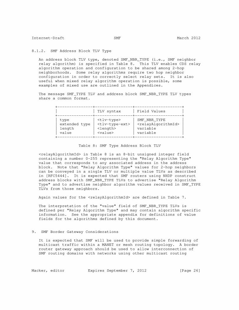
Internet-Draft SMF March 2012
8.1.2. SMF Address Block TLV Type
An address block TLV type, denoted SMF_NBR_TYPE (i.e., SMF neighbor relay algorithm) is specified in Table 8. This TLV enables CDS relay algorithm operation and configuration to be shared among 2-hop neighborhoods. Some relay algorithms require two hop neighbor configuration in order to correctly select relay sets. It is also useful when mixed relay algorithm operation is possible, some examples of mixed use are outlined in the Appendices.
The message SMF_TYPE TLV and address block SMF_NBR_TYPE TLV types share a common format.
+---------------+----------------+--------------------+ | | TLV syntax | Field Values | +---------------+----------------+--------------------+ | type | <tlv-type> | SMF_NBR_TYPE | | extended type | <tlv-type-ext> | <relayAlgorithmId> | | length | <length> | variable | | value | <value> | variable | +---------------+----------------+--------------------+
Table 8: SMF Type Address Block TLV
<relayAlgorithmId> in Table 8 is an 8-bit unsigned integer field containing a number 0-255 representing the "Relay Algorithm Type" value that corresponds to any associated address in the address block. Note that "Relay Algorithm Type" values for 2-hop neighbors can be conveyed in a single TLV or multiple value TLVs as described in [RFC5444]. It is expected that SMF routers using NHDP construct address blocks with SMF_NBR_TYPE TLVs to advertise "Relay Algorithm Type" and to advertise neighbor algorithm values received in SMF_TYPE TLVs from those neighbors.
Again values for the <relayAlgorithmId> are defined in Table 7.
The interpretation of the "value" field of SMF_NBR_TYPE TLVs is defined per "Relay Algorithm Type" and may contain algorithm specific information. See the appropriate appendix for definitions of value fields for the algorithms defined by this document.
9. SMF Border Gateway Considerations
It is expected that SMF will be used to provide simple forwarding of multicast traffic within a MANET or mesh routing topology. A border router gateway approach should be used to allow interconnection of SMF routing domains with networks using other multicast routing
Macker, editor Expires September 7, 2012 [Page 26]

Internet-Draft SMF March 2012
protocols, such as PIM. It is important to note that there are many scenario-specific issues that should be addressed when discussing border multicast routers. At the present time, experimental deployments of SMF and PIM border router approaches have been demonstrated [DHS08]. Some of the functionality border routers may need to address includes the following:
1. Determining which multicast group traffic transits the border router whether entering or exiting the attached SMF routing domain. 2. Enforcement of TTL/hop-limit threshold or other scoping policies. 3. Any marking or labeling to enable DPD on ingressing packets. 4. Interface with exterior multicast routing protocols. 5. Possible operation with multiple border routers (presently beyond scope of this document). 6. Provisions for participating non-SMF devices (routers or hosts).
Each of these areas is discussed in more detail in the following subsections. Note the behavior of SMF border routers is the same as that of non-border SMF routers when forwarding packets on interfaces within the SMF routing domain. Packets that are passed outbound to interfaces operating fixed-infrastructure multicast routing protocols SHOULD be evaluated for duplicate packet status since present standard multicast forwarding mechanisms do not usually perform this function.
9.1. Forwarded Multicast Groups
Mechanisms for dynamically determining groups for forwarding into a MANET SMF routing domain is an evolving technology area. Ideally, only traffic for which there is active group membership should be injected into the SMF domain. This can be accomplished by providing an IPv4 Internet Group Membership Protocol (IGMP) or IPv6 Multicast Listener Discovery (MLD) proxy protocol so that MANET SMF routers can inform attached border routers (and hence multicast networks) of their current group membership status. For specific systems and services it may be possible to statically configure group membership joins in border routers, but it is RECOMMENDED that some form of IGMP/MLD proxy or other explicit, dynamic control of membership be provided. Specification of such an IGMP/MLD proxy protocol is beyond the scope of this document.
For outbound traffic, SMF border routers perform duplicate packet detection and forward non-duplicate traffic that meets TTL/hop limit and scoping criteria to interfaces external to the SMF routing domain. Appropriate IP multicast routing (e.g., PIM-based solutions) on those interfaces can make further forwarding decisions with respect to the multicast packet. Note that the presence of multiple
Macker, editor Expires September 7, 2012 [Page 27]

Internet-Draft SMF March 2012
border routers associated with a MANET routing domain raises additional issues. This is further discussed in Section 9.4 but further work is expected to be needed here.
9.2. Multicast Group Scoping
Multicast scoping is used by network administrators to control the network routing domains reachable by multicast packets. This is usually done by configuring external interfaces of border routers in the border of a routing domain to not forward multicast packets which must be kept within the SMF routing domain. This is commonly done based on TTL/hop-limit of messages or by using adminstratively scoped group addresses. These schemes are known respectively as:
1. TTL scoping. 2. Administrative scoping.
For IPv4, network administrators can configure border routers with the appropriate TTL/hop-limit thresholds or administratively scoped multicast groups for the router interfaces as with any traditional multicast router. However, for the case of TTL/hop-limit scoping it SHOULD be taken into account that the packet could traverse multiple hops within the MANET SMF routing domain before reaching the border router. Thus, TTL thresholds SHOULD be selected carefully.
For IPv6, multicast address spaces include information about the scope of the group. Thus, border routers of an SMF routing domain know if they must forward a packet based on the IPv6 multicast group address. For the case of IPv6, it is RECOMMENDED that a MANET SMF routing domain be designated a site-scoped multicast domain. Thus, all IPv6 site-scoped multicast packets in the range FF05::/16 SHOULD be kept within the MANET SMF routing domain by border routers. IPv6 packets in any other wider range scopes (i.e. FF08::/16, FF0B::/16 and FF0E::16) MAY traverse border routers unless other restrictions different from the scope applies.
Given that scoping of multicast packets is performed at the border routers, and given that existing scoping mechanisms are not designed to work with mobile routers, it is assumed that non-border routers running SMF will not stop forwarding multicast data packets of an appropriate site scoping. That is, it is assumed that an SMF routing domain is a site-scoped multicast area.
9.3. Interface with Exterior Multicast Routing Protocols
The traditional operation of multicast routing protocols is tightly integrated with the group membership function. Leaf routers are configured to periodically gather group membership information, while
Macker, editor Expires September 7, 2012 [Page 28]
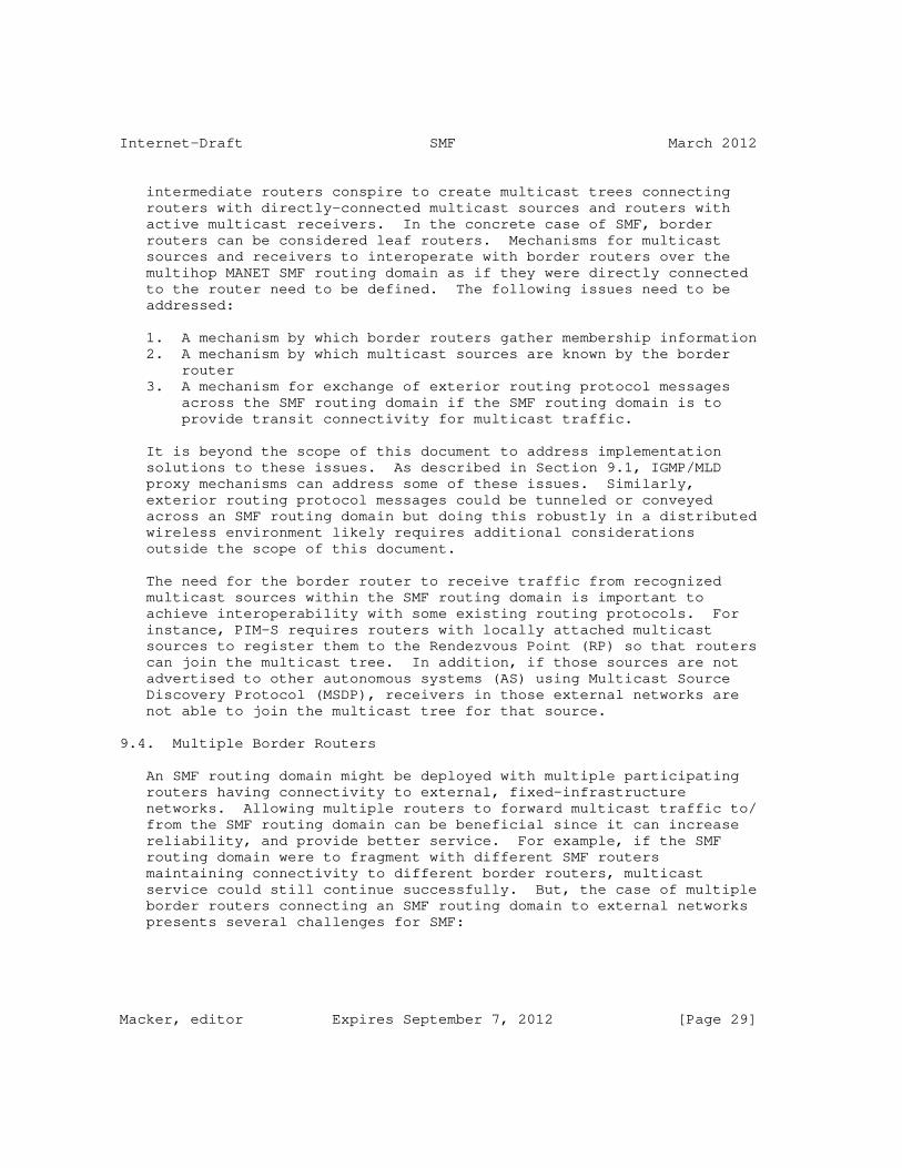
Internet-Draft SMF March 2012
intermediate routers conspire to create multicast trees connecting routers with directly-connected multicast sources and routers with active multicast receivers. In the concrete case of SMF, border routers can be considered leaf routers. Mechanisms for multicast sources and receivers to interoperate with border routers over the multihop MANET SMF routing domain as if they were directly connected to the router need to be defined. The following issues need to be addressed:
1. A mechanism by which border routers gather membership information 2. A mechanism by which multicast sources are known by the border router 3. A mechanism for exchange of exterior routing protocol messages across the SMF routing domain if the SMF routing domain is to provide transit connectivity for multicast traffic.
It is beyond the scope of this document to address implementation solutions to these issues. As described in Section 9.1, IGMP/MLD proxy mechanisms can address some of these issues. Similarly, exterior routing protocol messages could be tunneled or conveyed across an SMF routing domain but doing this robustly in a distributed wireless environment likely requires additional considerations outside the scope of this document.
The need for the border router to receive traffic from recognized multicast sources within the SMF routing domain is important to achieve interoperability with some existing routing protocols. For instance, PIM-S requires routers with locally attached multicast sources to register them to the Rendezvous Point (RP) so that routers can join the multicast tree. In addition, if those sources are not advertised to other autonomous systems (AS) using Multicast Source Discovery Protocol (MSDP), receivers in those external networks are not able to join the multicast tree for that source.
9.4. Multiple Border Routers
An SMF routing domain might be deployed with multiple participating routers having connectivity to external, fixed-infrastructure networks. Allowing multiple routers to forward multicast traffic to/ from the SMF routing domain can be beneficial since it can increase reliability, and provide better service. For example, if the SMF routing domain were to fragment with different SMF routers maintaining connectivity to different border routers, multicast service could still continue successfully. But, the case of multiple border routers connecting an SMF routing domain to external networks presents several challenges for SMF:
Macker, editor Expires September 7, 2012 [Page 29]

Internet-Draft SMF March 2012
1. Handling duplicate unmarked IPv4 or IPv6 (without IPsec encapsulation or DPD option) packets possibly injected by multiple border routers. 2. Source-based relay algorithms handling of duplicate traffic injected by multiple border routers. 3. Determination of which border router(s) will forward outbound multicast traffic. 4. Additional challenges with interfaces to exterior multicast routing protocols.
When multiple border routers are present they may be alternatively (due to route changes) or simultaneously injecting common traffic into the SMF routing domain that has not been previously marked for IPv6 SMF_DPD. Different border routers would not be able to implicitly synchronize sequencing of injected traffic since they may not receive exactly the same messages due to packet losses. For IPv6 I-DPD operation, the optional "TaggerId" field described for the SMF_DPD header option can be used to mitigate this issue. When multiple border routers are injecting a flow into an SMF routing domain, there are two forwarding policies that SMF routers running I-DPD may implement:
1. Redundantly forward the multicast flows (identified by <srcAddr: dstAddr>) from each border router, performing DPD processing on a <TaggerID:dstAddr> or <TaggerID:srcAddr:dstAddr> basis, or 2. Use some basis to select the flow of one tagger (border router) over the others and forward packets for applicable flows (identified by <sourceAddress:dstAddr>) only for the selected "Tagger ID" until timeout or some other criteria to favor another tagger occurs.
It is RECOMMENDED that the first approach be used in the case of I-DPD operation. Additional specification may be required to describe an interoperable forwarding policy based on this second option. Note that the implementation of the second option requires that per-flow (i.e., <srcAddr::dstAddr>) state be maintained for the selected "Tagger ID".
The deployment of H-DPD operation may alleviate DPD resolution when ingressing traffic comes from multiple border routers. Non-colliding hash indexes (those not requiring the H-DPD options header in IPv6) should be resolved effectively.
10. Security Considerations
Gratuitous use of option headers can cause problems in routers. Other IP routers external to an SMF routing domain that might receive
Macker, editor Expires September 7, 2012 [Page 30]

Internet-Draft SMF March 2012
forwarded multicast SHOULD ignore SMF-specific IPv6 header options when encountered. The header options types are encoded appropriately to allow for this behavior.
This section briefly discusses several SMF denial-of-service (DoS) attack scenarios and we provide some initial recommended mitigation strategies.
A potential denial-of-service attack against SMF forwarding is possible when a malicious router has a form of wormhole access to non-adjacent parts of a network topology. In the wireless ad hoc case, a directional antenna is one way to provide such a wormhole physically. If such a router can preview forwarded packets in a non- adjacent part of the network and forward modified versions to another part of the network it can perform the following attack. The malicious router could reduce the TTL/hop-limit or Hop Limit of the packet and transmit it to the SMF router causing it to forward the packet with a limited TTL/hop-limit (or even drop it) and make a DPD entry that could block or limit the subsequent forwarding of later- arriving valid packets with correct TTL/hop-limit values. This would be a relatively low-cost, high-payoff attack that would be hard to detect and thus attractive to potential attackers. An approach of caching TTL/hop-limit information with DPD state and taking appropriate forwarding actions is identified in Section 5 to mitigate this form of attack.
Sequence-based packet identifiers are predictable and thus provide an opportunity for a DoS attack against forwarding. Forwarding protocols that use DPD techniques, such as SMF, may be vulnerable to DoS attacks based on spoofing packets with apparently valid packet identifier fields. In wireless environments, where SMF will most likely be used, the opportunity for such attacks may be more prevalent than in wired networks. In the case of IPv4 packets, fragmented IP packets or packets with IPsec headers applied, the DPD "identifier portions" of potential future packets that might be forwarded is highly predictable and easily subject to DoS attacks against forwarding. A RECOMMENDED technique to counter this concern is for SMF implementations to generate an "internal" hash value that is concatenated with the explicit I-DPD packet identifier to form a unique identifier that is a function of the packet content as well as the visible identifier. SMF implementations could seed their hash generation with a random value to make it unlikely that an external observer could guess how to spoof packets used in a denial-of-service attack against forwarding. Since the hash computation and state is kept completely internal to SMF routers, the cryptographic properties of this hashing would not need to be extensive and thus possibly of low complexity. Experimental implementations may determine that a lightweight hash of even only portions of packets may suffice to
Macker, editor Expires September 7, 2012 [Page 31]

Internet-Draft SMF March 2012
serve this purpose.
While H-DPD is not as readily susceptible to this form of DoS attack, it is possible that a sophisticated adversary could use side information to construct spoofing packets to mislead forwarders using a well-known hash algorithm. Thus, similarly, a separate "internal" hash value could be concatenated with the well-known hash value to alleviate this security concern.
The support of forwarding IPsec packets without further modification for both IPv4 and IPv6 is supported by this specification.
Authentication mechanisms to identify the source of IPv6 option headers should be considered to reduce vulnerability to a variety of attacks.
Furthermore, when the MANET Neighborhood Discovery Protocol [RFC6130] is used, the security considerations described there also applies.
11. IANA Considerations
This document defines one IPv6 Hop-by-Hop Option, a type for which which must be allocated from the IPv6 "Destination Options and Hop- by-Hop Options" registry of [RFC2780].
This document creates one registry for recording TaggerId types, (TidTy).
This document requests registration of one well-known multicast address from each of the IPv4 and IPv6 multicast address spaces.
This document defines one Message TLV, a type for which must be allocated from the "Message TLV Types" registry of [RFC5444].
Finally, this document defines one Address Block TLV, a type for which must be allocated from the "Address Block TLV Types" registry of [RFC5444].
11.1. IPv6 SMF_DPD Header Extension Option Type
IANA is requested to allocate an IPv6 Option Type from the IPv6 "Destination Options and Hop-by-Hop Options" registry of [RFC2780], as specified in Table 9.
Macker, editor Expires September 7, 2012 [Page 32]
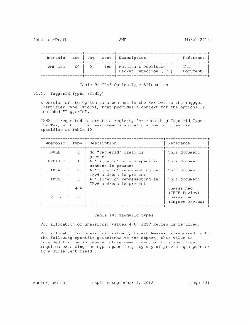
Internet-Draft SMF March 2012
+----------+-----+-----+------+-------------------------+-----------+ | Mnemonic | act | chg | rest | Description | Reference | +----------+-----+-----+------+-------------------------+-----------+ | SMF_DPD | 00 | 0 | TBD | Multicast Duplicate | This | | | | | | Packet Detection (DPD) | Document | +----------+-----+-----+------+-------------------------+-----------+
Table 9: IPv6 Option Type Allocation
11.2. TaggerId Types (TidTy)
A portion of the option data content in the SMF_DPD is the Taggger Identifier Type (TidTy), that provides a context for the optionally included "TaggerId".
IANA is requested to create a registry for recording TaggerId Types (TidTy), with initial assignments and allocation policies, as specified in Table 10.
+----------+------+-------------------------------+-----------------+ | Mnemonic | Type | Description | Reference | +----------+------+-------------------------------+-----------------+ | NULL | 0 | No "TaggerId" field is | This document | | | | present | | | DEFAULT | 1 | A "TaggerId" of non-specific | This document | | | | context is present | | | IPv4 | 2 | A "TaggerId" representing an | This document | | | | IPv4 address is present | | | IPv6 | 3 | A "TaggerId" representing an | This document | | | | IPv6 address is present | | | | 4-6 | | Unassigned | | | | | (IETF Review) | | ExtId | 7 | | Unassigned | | | | | (Expert Review) | +----------+------+-------------------------------+-----------------+
Table 10: TaggerId Types
For allocation of unassigned values 4-6, IETF Review is required.
For allocation of unassigned value 7, Expert Review is required, with the following specific guidelines to the Expert: this value is intended for use in case a future development of this specification requires extending the type space (e.g. by way of providing a pointer to a subsequent field).
Macker, editor Expires September 7, 2012 [Page 33]

Internet-Draft SMF March 2012
11.3. Well-known Multicast Address
IANA is requested to allocate an IPv4 multicast address "SL-MANET- ROUTERS" from the "Internetwork Control Block (224.0.1/24)" sub- registry of the "IPv4 Multicast Address" registry.
IANA is requested to allocate an IPv6 multicast address "SL-MANET- ROUTERS" from the "Site-Local Scope Multicast Addresses" sub-sub- registry of the "Fixed Scope Multicast Addresses" sub-registry of the "INTERNET PROTOCOL VERSION 6 MULTICAST ADDRESSES" registry.
11.4. SMF Type-Length-Values
11.4.1. Expert Review for created Type Extension Registries
Creation of Address Block TLV Types and Message TLV Types in registries of [RFC5444], and hence in the HELLO message specific registries of [RFC6130], entails creation of corresponding Type Extension registries for each such type. For such Type Extension registries, where an Expert Review is required, the designated expert SHOULD take the same general recommendations into consideration as are specified by [RFC5444].
11.4.2. SMF Message TLV Type (SMF_TYPE)
This document defines one Message TLV Type, "SMF_TYPE", which must be allocated from the "HELLO Message-Type-specific Message TLV Types" registry, defined in [RFC6130].
This will create a new Type Extension registry, with initial assignments as specified in Table 11.
+----------+------+-----------+--------------------+----------------+ | Name | Type | Type | Description | Allocation | | | | Extension | | Policy | +----------+------+-----------+--------------------+----------------+ | SMF_TYPE | TBD2 | 0-255 | Specifies relay | Section 11.4.4 | | | | | algorithm | | | | | | supported by the | | | | | | SMF router, | | | | | | originating the | | | | | | HELLO message, | | | | | | according to | | | | | | Section 11.4.4. | | +----------+------+-----------+--------------------+----------------+
Table 11: SMF_TYPE Message TLV Type Extension Registry
Macker, editor Expires September 7, 2012 [Page 34]

Internet-Draft SMF March 2012
11.4.3. SMF Address Block TLV Type (SMF_NBR_TYPE)
This document defines one Address Block TLV Type, "SMF_NBR_TYPE", which must be allocated from the "HELLO Message-Type-specific Address Block TLV Types" registry, defined in [RFC6130].
This will create a new Type Extension registry, with initial assignments as specified in Table 12.
+-------------+------+-----------+-----------------+----------------+ | Name | Type | Type | Description | Allocation | | | | Extension | | Policy | +-------------+------+-----------+-----------------+----------------+ | SMF_NBR_TYP | TBD2 | 0-255 | Specifies relay | Section 11.4.4 | | E | | | algorithm | | | | | | supported by | | | | | | the SMF router | | | | | | corresponding | | | | | | to the | | | | | | advertised | | | | | | address, | | | | | | according to | | | | | | Section 11.4.4. | | +-------------+------+-----------+-----------------+----------------+
Table 12: SMF_NBR_TYPE Address Block TLV Type Extension Registry
11.4.4. SMF Relay Algorithm ID Registry
Types for the Type Extension Registries for the SMF_TYPE Message TLV and the SMF_NBR_TYPE Address Block TLV are unified in this single SMF Relay Algorithm ID Registry, defined in this section.
IANA is requested to create a registry for recording Relay Algorithm Identifiers, with initial assignments and allocation policies as specified in Table 13.
+---------+---------+-------------+-------------------+ | Name | Value | Description | Allocation Policy | +---------+---------+-------------+-------------------+ | CF | 0 | Section 4 | | | S-MPR | 1 | Appendix B | | | E-CDS | 2 | Appendix A | | | MPR-CDS | 3 | Appendix C | | | | 4-127 | Unassigned | Expert Review | | | 128-255 | Unassigned | Experimental Use | +---------+---------+-------------+-------------------+
Macker, editor Expires September 7, 2012 [Page 35]
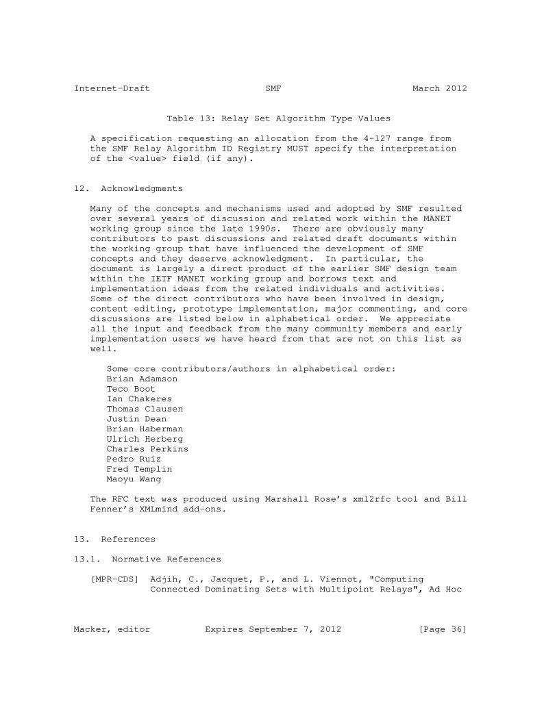
Internet-Draft SMF March 2012
Table 13: Relay Set Algorithm Type Values
A specification requesting an allocation from the 4-127 range from the SMF Relay Algorithm ID Registry MUST specify the interpretation of the <value> field (if any).
12. Acknowledgments
Many of the concepts and mechanisms used and adopted by SMF resulted over several years of discussion and related work within the MANET working group since the late 1990s. There are obviously many contributors to past discussions and related draft documents within the working group that have influenced the development of SMF concepts and they deserve acknowledgment. In particular, the document is largely a direct product of the earlier SMF design team within the IETF MANET working group and borrows text and implementation ideas from the related individuals and activities. Some of the direct contributors who have been involved in design, content editing, prototype implementation, major commenting, and core discussions are listed below in alphabetical order. We appreciate all the input and feedback from the many community members and early implementation users we have heard from that are not on this list as well.
Some core contributors/authors in alphabetical order: Brian Adamson Teco Boot Ian Chakeres Thomas Clausen Justin Dean Brian Haberman Ulrich Herberg Charles Perkins Pedro Ruiz Fred Templin Maoyu Wang
The RFC text was produced using Marshall Rose’s xml2rfc tool and Bill Fenner’s XMLmind add-ons.
13. References
13.1. Normative References
[MPR-CDS] Adjih, C., Jacquet, P., and L. Viennot, "Computing Connected Dominating Sets with Multipoint Relays", Ad Hoc
Macker, editor Expires September 7, 2012 [Page 36]

Internet-Draft SMF March 2012
and Sensor Wireless Networks , January 2005.
[RFC0791] Postel, J., "Internet Protocol", STD 5, RFC 791, September 1981.
[RFC2119] Bradner, S., "Key words for use in RFCs to Indicate Requirement Levels", BCP 14, RFC 2119, March 1997.
[RFC2460] Deering, S. and R. Hinden, "Internet Protocol, Version 6 (IPv6) Specification", RFC 2460, December 1998.
[RFC2644] Senie, D., "Changing the Default for Directed Broadcasts in Routers", BCP 34, RFC 2644, August 1999.
[RFC2780] Bradner, S. and V. Paxson, "IANA Allocation Guidelines For Values In the Internet Protocol and Related Headers", BCP 37, RFC 2780, March 2000.
[RFC3174] Eastlake, D. and P. Jones, "US Secure Hash Algorithm 1 (SHA1)", RFC 3174, September 2001.
[RFC3626] Clausen, T. and P. Jacquet, "Optimized Link State Routing Protocol (OLSR)", RFC 3626, October 2003.
[RFC4291] Hinden, R. and S. Deering, "IP Version 6 Addressing Architecture", RFC 4291, February 2006.
[RFC4302] Kent, S., "IP Authentication Header", RFC 4302, December 2005.
[RFC5226] Narten, T. and H. Alvestrand, "Guidelines for Writing an IANA Considerations Section in RFCs", BCP 26, RFC 5226, May 2008.
[RFC5444] Clausen, T., Dearlove, C., Dean, J., and C. Adjih, "Generalized Mobile Ad Hoc Network (MANET) Packet/Message Format", RFC 5444, February 2009.
[RFC5614] Ogier, R. and P. Spagnolo, "Mobile Ad Hoc Network (MANET) Extension of OSPF Using Connected Dominating Set (CDS) Flooding", RFC 5614, August 2009.
[RFC5771] Cotton, M., Vegoda, L., and D. Meyer, "IANA Guidelines for IPv4 Multicast Address Assignments", BCP 51, RFC 5771, March 2010.
[RFC6130] Clausen, T., Dearlove, C., and J. Dean, "Mobile Ad Hoc Network (MANET) Neighborhood Discovery Protocol (NHDP)",
Macker, editor Expires September 7, 2012 [Page 37]

Internet-Draft SMF March 2012
RFC 6130, April 2011.
13.2. Informative References
[CDHM07] Chakeres, I., Danilov, C., and T. Henderson, "Connecting MANET Multicast", IEEE MILCOM 2007 Proceedings , 2007.
[DHG09] Danilov, C., Henderson, T., and T. Goff, "Experiment and field demonstration of a 802.11-based ground-UAV mobile ad-hoc network", Proceedings of the 28th IEEE conference on Military Communications , 2009.
[DHS08] Danilov, C., Henderson, T., and T. Spagnolo, "MANET Multicast with Multiple Gateways", IEEE MILCOM 2008 Proceedings , 2008.
[GM99] Garcia-Luna-Aceves, JJ. and E. Madruga, "The core-assisted mesh protocol", Selected Areas in Communications, IEEE Journal on Volume 17, Issue 8, August 1999.
[I-D.ietf-intarea-ipv4-id-update] Touch, J., "Updated Specification of the IPv4 ID Field", draft-ietf-intarea-ipv4-id-update-04 (work in progress), September 2011.
[JLMV02] Jacquet, P., Laouiti, V., Minet, P., and L. Viennot, "Performance of multipoint relaying in ad hoc mobile routing protocols", Networking , 2002.
[MDC04] Macker, J., Dean, J., and W. Chao, "Simplified Multicast Forwarding in Mobile Ad hoc Networks", IEEE MILCOM 2004 Proceedings , 2004.
[MDDA07] Macker, J., Downard, I., Dean, J., and R. Adamson, "Evaluation of distributed cover set algorithms in mobile ad hoc network for simplified multicast forwarding", ACM SIGMOBILE Mobile Computing and Communications Review Volume 11 , Issue 3, July 2007.
[MGL04] Mohapatra, P., Gui, C., and J. Li, "Group Communications in Mobile Ad hoc Networks", IEEE Computer Vol. 37, No. 2, February 2004.
[NTSC99] Ni, S., Tseng, Y., Chen, Y., and J. Sheu, "The Broadcast Storm Problem in Mobile Ad hoc Networks", Proceedings Of ACM Mobicom 99 , 1999.
[RFC2501] Corson, M. and J. Macker, "Mobile Ad hoc Networking
Macker, editor Expires September 7, 2012 [Page 38]

Internet-Draft SMF March 2012
(MANET): Routing Protocol Performance Issues and Evaluation Considerations", RFC 2501, January 1999.
[RFC3684] Ogier, R., Templin, F., and M. Lewis, "Topology Dissemination Based on Reverse-Path Forwarding (TBRPF)", RFC 3684, February 2004.
[RFC3973] Adams, A., Nicholas, J., and W. Siadak, "Protocol Independent Multicast - Dense Mode (PIM-DM): Protocol Specification (Revised)", RFC 3973, January 2005.
[RFC4601] Fenner, B., Handley, M., Holbrook, H., and I. Kouvelas, "Protocol Independent Multicast - Sparse Mode (PIM-SM): Protocol Specification (Revised)", RFC 4601, August 2006.
Appendix A. Essential Connecting Dominating Set (E-CDS) Algorithm
The "Essential Connected Dominating Set" (E-CDS) algorithm [RFC5614] forms a single CDS mesh for the SMF operating region. It allows routers to use 2-hop neighborhood topology information to dynamically perform relay self election to form a CDS. Its packet forwarding rules are not dependent upon previous hop knowledge. Additionally, E-CDS SMF forwarders can be easily mixed without problems with CF SMF forwarders, even those not participating in NHDP. Another benefit is that packets opportunistically received from non-symmetric neighbors may be forwarded without compromising flooding efficiency or correctness. Furthermore, multicast sources not participating in NHDP may freely inject their traffic and any neighboring E-CDS relays will properly forward the traffic. The E-CDS based relay set selection algorithm is based upon [RFC5614]. E-CDS was originally discussed in the context of forming partial adjacencies and efficient flooding for MANET OSPF extensions work and the core algorithm is applied here for SMF.
It is RECOMMENDED that the SMF_TYPE:E-CDS Message TLV be included in NHDP_HELLO messages that are generated by routers conducting E-CDS SMF operation. It is also RECOMMENDED that the SMF_NBR_TYPE:E-CDS address block TLV be used to advertise neighbor routers that are also conducting E-CDS SMF operation.
A.1. E-CDS Relay Set Selection Overview
The E-CDS relay set selection requires 2-hop neighborhood information collected through NHDP or another process. Relay routers, in E-CDS SMF selection, are "self-elected" using a router identifier (Router ID) and an optional nodal metric, referred to here as "Router Priority" for all 1-hop and 2-hop neighbors. To ensure proper relay
Macker, editor Expires September 7, 2012 [Page 39]

Internet-Draft SMF March 2012
set self-election, the Router ID and Router Priority MUST be consistent among participating routers. It is RECOMMENDED that NHDP be used to share Router ID and Router Priority through the use of SMF_TYPE:E-CDS TLVs as described in this appendix. The Router ID is a logical identification that MUST be consistent across interoperating SMF neighborhoods and it is RECOMMENDED to be chosen as the numerically largest address contained in a routers "Neighbor Address List" as defined in NHDP. The E-CDS self-election process can be summarized as follows:
1. If an SMF router has a higher ordinal (Router Priority, Router ID) than all of its symmetric neighbors, it elects itself to act as a forwarder for all received multicast packets, 2. Else, if there does not exist a path from the neighbor with largest (Router Priority, Router ID) to any other neighbor, via neighbors with larger values of (Router Priority, Router ID), then it elects itself to the relay set.
The basic form of E-CDS described and applied within this specification does not provide for redundant relay set election (e.g., bi-connected) but such capability is supported by the basic E-CDS design.
A.2. E-CDS Forwarding Rules
With E-CDS, any SMF router that has selected itself as a relay performs DPD and forwards all non-duplicative multicast traffic allowed by the present forwarding policy. Packet previous hop knowledge is not needed for forwarding decisions when using E-CDS.
1. Upon packet reception, DPD is performed. Note E-CDS requires a single duplicate table for the set of interfaces associated with the relay set selection. 2. If the packet is a duplicate, no further action is taken. 3. If the packet is non-duplicative: A. A DPD entry is made for the packet identifier B. The packet is forwarded out all interfaces associated with the relay set selection
As previously mentioned, even packets sourced (or relayed) by routers not participating in NHDP and/or the E-CDS relay set selection may be forwarded by E-CDS forwarders without problem. A particular deployment MAY choose to not forward packets from previous hop routers that have been not explicitly identified via NHDP or other means as operating as part of a different relay set algorithm (e.g. S-MPR) to allow coexistent deployments to operate correctly. Also, E-CDS relay set selection may be configured to be influenced by statically-configured CF relays that are identified via NHDP or other
Macker, editor Expires September 7, 2012 [Page 40]

Internet-Draft SMF March 2012
means.
A.3. E-CDS Neighborhood Discovery Requirements
It is possible to perform E-CDS relay set selection without modification of NHDP, basing the self-election process exclusively on the "Neighbor Address List" of participating SMF routers. For example by setting the "Router Priority" to a default value and selecting the "Router ID" as the numerically largest address contained in the "Neighbor Address List". However steps MUST be taken to insure that all NHDP enabled routers not using SMF_TYPE:E- CDS full type Message TLVs are in fact running SMF E-CDS with the same methods for selecting "Router Priority" and "Router ID", otherwise incorrect forwarding may occur. Note that SMF routers with higher "Router Priority" values will be favored as relays over routers with lower "Router Priority". Thus, preferred relays MAY be administratively configured to be selected when possible. Additionally, other metrics (e.g. nodal degree, energy capacity, etc) may also be taken into account in constructing a "Router Priority" value. When using "Router Priority" with multiple interfaces all interfaces on a router MUST use and advertise a common "Router Priority" value. A routers "Router Priority" value may be administratively or algorithmically selected. The method of selection does not need to be the same among different routers.
E-CDS relay set selection may be configured to be influenced by statically configured CF relays that are identified via NHDP or other means. Nodes advertising CF through NHDP may be considered E-CDS SMF routers with maximal "Router Priority".
To share a router’s "Router Priority" with its 1-hop neighbors the SMF_TYPE:E-CDS Message TLV’s <value> field is defined as shown in Table 14.
+---------------+---------+-----------------+ | Length(bytes) | Value | Router Priority | +---------------+---------+-----------------+ | 0 | N/A | 64 | | 1 | <value> | 0-127 | +---------------+---------+-----------------+
Table 14: E-CDS Message TLV Values
Where <value> is a one octet long bit field which is defined as:
bit 0: the leftmost bit is reserved and SHOULD be set to 0.
bit 1-7: contain the unsigned "Router Priority" value, 0-127, which
Macker, editor Expires September 7, 2012 [Page 41]

Internet-Draft SMF March 2012
is associated with the "Neighbor Address List".
Combinations of value field lengths and values other than specified here are NOT permitted and SHOULD be ignored. Figure 5 shows an example SMF_TYPE:E-CDS Message TLV
0 1 2 3 0 1 2 3 4 5 6 7 8 9 0 1 2 3 4 5 6 7 8 9 0 1 2 3 4 5 6 7 8 9 0 1 +-+-+-+-+-+-+-+-+-+-+-+-+-+-+-+-+-+-+-+-+-+-+-+-+-+-+-+-+-+-+-+-+ ... | SMF_TYPE |1|0|0|1|0|0| | +-+-+-+-+-+-+-+-+-+-+-+-+-+-+-+-+-+-+-+-+-+-+-+-+-+-+-+-+-+-+-+-+ | E-CDS |0|0|0|0|0|0|0|1|R| priority | ... | +-+-+-+-+-+-+-+-+-+-+-+-+-+-+-+-+-+-+-+-+-+-+-+-+-+-+-+-+-+-+-+-+
Figure 5: E-CDS Message TLV Example
To convey "Router Priority" values among 2-hop neighborhoods the SMF_NBR_TYPE:E-CDS address block TLV’s <value> field is used. Multi- index and multi-value TLV layouts as defined in [RFC5444] are supported. SMF_NBR_TYPE:E-CDS value fields are defined thus:
+---------------+--------+----------+-------------------------------+ | Length(bytes) | # Addr | Value | Router Priority | +---------------+--------+----------+-------------------------------+ | 0 | Any | N/A | 64 | | 1 | Any | <value> | <value> is for all addresses | | N | N | <value>* | Each address gets its own | | | | | <value> | +---------------+--------+----------+-------------------------------+
Table 15: E-CDS Address Block TLV Values
Where <value> is a one byte bit field which is defined as:
bit 0: the leftmost bit is reserved and SHOULD be set to 0.
bit 1-7: contain the unsigned "Router Priority" value, 0-127, which is associated with the appropriate address(es).
Combinations of value field lengths and # of addresses other than specified here are NOT permitted and SHOULD be ignored. A default technique of using nodal degree (i.e. count of 1-hop neighbors) is RECOMMENDED for the value field of these TLV types. Below are two example SMF_NBR_TYPE:E-CDS address block TLVs.
Macker, editor Expires September 7, 2012 [Page 42]

Internet-Draft SMF March 2012
0 1 2 3 0 1 2 3 4 5 6 7 8 9 0 1 2 3 4 5 6 7 8 9 0 1 2 3 4 5 6 7 8 9 0 1 +-+-+-+-+-+-+-+-+-+-+-+-+-+-+-+-+-+-+-+-+-+-+-+-+-+-+-+-+-+-+-+-+ ... | SMF_NBR_TYPE |1|0|0|1|0|0| | +-+-+-+-+-+-+-+-+-+-+-+-+-+-+-+-+-+-+-+-+-+-+-+-+-+-+-+-+-+-+-+-+ | E-CDS |0|0|0|0|0|0|0|1|R| priority | ... | +-+-+-+-+-+-+-+-+-+-+-+-+-+-+-+-+-+-+-+-+-+-+-+-+-+-+-+-+-+-+-+-+
Figure 6: E-CDS Address Block TLV Example 1
The single value example TLV, depicted in Figure 6 , specifies that all address(es) contained in the address block are running SMF using the E-CDS algorithm and all address(es) share the value field and therefore the same "Router Priority". 0 1 2 3 0 1 2 3 4 5 6 7 8 9 0 1 2 3 4 5 6 7 8 9 0 1 2 3 4 5 6 7 8 9 0 1 +-+-+-+-+-+-+-+-+-+-+-+-+-+-+-+-+-+-+-+-+-+-+-+-+-+-+-+-+-+-+-+-+ ... | SMF_NBR_TYPE |1|0|1|1|0|1| | +-+-+-+-+-+-+-+-+-+-+-+-+-+-+-+-+-+-+-+-+-+-+-+-+-+-+-+-+-+-+-+-+ | E-CDS | index-start | index-end | length | +-+-+-+-+-+-+-+-+-+-+-+-+-+-+-+-+-+-+-+-+-+-+-+-+-+-+-+-+-+-+-+-+ |R| priority0 |R| priority1 | ... |R| priorityN | +-+-+-+-+-+-+-+-+-+-+-+-+-+-+-+-+-+-+-+-+-+-+-+-+-+-+-+-+-+-+-+-+
Figure 7: E-CDS Address Block TLV Example 2
The example multivalued TLV, depicted in Figure 7, specifies that address(es) contained in the address block from index-start to index- end inclusive are running SMF using the E-CDS algorithm. Each address is associated with its own value byte and therefore its own "Router Priority".
A.4. E-CDS Selection Algorithm
This section describes an algorithm for E-CDS relay selection (self- election). The algorithm described uses 2-hop information. Note it is possible to extend this algorithm to use k-hop information with added computational complexity and mechanisms for sharing k-hop topology information that are not described in this document or within the NHDP specification. It should also be noted that this algorithm does not impose the "hop limit" bound described in [RFC5614] when performing the path search that is used for relay selection. However, the algorithm below could be easily augmented to accommodate this additional criterion. It is not expected that the "hop limit" bound will provide significant benefit to the algorithm defined in this appendix.
The tuple of "Router Priority" and "Router ID" is used in E-CDS relay
Macker, editor Expires September 7, 2012 [Page 43]

Internet-Draft SMF March 2012
set selection. Precedence is given to the "Router Priority" portion and the "Router ID" value is used as a tie-breaker. The evaluation of this tuple is referred to as "RtrPri(n)" in the description below where "n" references a specific router. Note it is possible that the "Router Priority" portion may be optional and the evaluation of "RtrPri()" be solely based upon the unique "Router ID". Since there MUST NOT be any duplicate "Router ID" values among SMF routers, a comparison of RtrPri(n) between any two routers will always be an inequality. The use of nodal degree for calculating "Router Priority" is RECOMMENDED as default and the largest IP address in the "Neighbor Address List" as advertised by NHDP MUST be used as the "Router ID". NHDP provides all interface address throughout the 2-hop neighborhood through HELLO messages, so explicitly conveying a "Router ID" is not necessary. The following steps describe a basic algorithm for conducting E-CDS relay selection for a router "n0": 1. Initialize the set "N1" with tuples ("Router Priority", "Router ID", "Neighbor Address List") for each 1-hop neighbor of "n0". 2. If "N1" has less than 2 tuples, then "n0" does not elect itself as a relay and no further steps are taken. 3. Initialize the set "N2" with tuples ("Router Priority", "Router ID", "2-hop address") for each "2-hop address" of "n0", where "2-hop address" is defined in NHDP. 4. If "RtrPri(n0)" is greater than that of all tuples in the union of "N1" and "N2", then "n0" selects itself as a relay and no further steps are taken. 5. Initialize all tuples in the union of "N1" and "N2" as "unvisited". 6. Find the tuple "n1_Max" that has the largest "RtrPri()" of all tuples in "N1" 7. Initialize queue "Q" to contain "n1_Max", marking "n1_Max" as "visited" 8. While router queue "Q" is not empty, remove router "x" from the head of "Q", and for each 1-hop neighbor "n" of router "x" (excluding "n0") that is not marked "visited" A. Mark router "n" as "visited" B. If "RtrPri(n)" is greater than "RtrPri(n0), append "n" to "Q" 9. If any tuple in "N1" remains "unvisited", then "n0" selects itself as a relay. Otherwise "n0" does not act as a relay. Note these steps are re-evaluated upon neighborhood status changes. Steps 5 through 8 of this procedure describe an approach to a path search. The purpose of this path search is to determine if paths exist from the 1-hop neighbor with maximum "RtrPri()" to all other 1-hop neighbors without traversing an intermediate router with a "RtrPri()" value less than "RtrPri(n0)". These steps comprise a breadth-first traversal that evaluates only paths that meet that criteria. If all 1-hop neighbors of "n0" are "visited" during this traversal, then the path search has succeeded and router "n0" does not need to provide relay. It can be assumed that other routers will
Macker, editor Expires September 7, 2012 [Page 44]

Internet-Draft SMF March 2012
provide relay operation to ensure SMF connectivity.
It is possible to extend this algorithm to consider neighboring SMF routers that are known to be statically configured for CF (always relaying). The modification to the above algorithm is to process such routers as having a maximum possible "Router Priority" value. It is expected that routers configured for CF and participating in NHDP would indicate this with use of the SMF_TYPE:CF and SMF_NBR_TYPE:CF TLV types in their NHDP_HELLO message and address blocks, respectively.
Appendix B. Source-based Multipoint Relay (S-MPR)
The source-based multipoint relay (S-MPR) set selection algorithm enables individual routers, using two-hop topology information, to select relays from their set of neighboring routers. Relays are selected so that forwarding to the router’s complete two-hop neighbor set is covered. This distributed relay set selection technique has been shown to approximate a minimal connected dominating set (MCDS) in [JLMV02]. Individual routers must collect two-hop neighborhood information from neighbors, determine an appropriate current relay set, and inform selected neighbors of their relay status. Note that since each router picks its neighboring relays independently, S-MPR forwarders depend upon previous hop information (e.g, source MAC address) to operate correctly. The Optimized Link State Routing (OLSR) protocol has used this algorithm and protocol for relay of link state updates and other control information [RFC3626] and it has been demonstrated operationally in dynamic network environments.
It is RECOMMENDED that the SMF_TYPE:S-MPR Message TLV be included in NHDP_HELLO messages that are generated by routers conducting S-MPR SMF operation. It is also RECOMMENDED that the SMF_NBR_TYPE:S-MPR address block TLV be used to specify which neighbor routers are conducting S-MPR SMF operation.
B.1. S-MPR Relay Set Selection Overview
The S-MPR algorithm uses bi-directional 1-hop and 2-hop neighborhood information collected via NHDP to select, from a router’s 1-hop neighbors, a set of relays that will cover the router’s entire 2-hop neighbor set upon forwarding. The algorithm described uses a "greedy" heuristic of first picking the 1-hop neighbor who will cover the most 2-hop neighbors. Then, excluding those 2-hop neighbors that have been covered, additional relays from its 1-hop neighbor set are iteratively selected until the entire 2-hop neighborhood is covered. Note that 1-hop neighbors also identified as 2-hop neighbors are considered as 1-hop neighbors only.
Macker, editor Expires September 7, 2012 [Page 45]

Internet-Draft SMF March 2012
NHDP HELLO messages supporting S-MPR forwarding operation SHOULD use the TLVs defined in Section 8.1 using the S-MPR extended type. The value field of an address block TLV which has a full type value of SMF_NBR_TYPE:S-MPR is defined in Table 17 such that signaling of MPR selections to 1-hop neighbors is possible. The value field of a message block TLV which has a full type value of SMF_TYPE:S-MPR is defined in Table 16 such that signaling of "Router Priority" (described as "WILLINGNESS" in [RFC3626]) to 1-hop neighbors is possible. It is important to note that S-MPR forwarding is dependent upon the previous hop of an incoming packet. An S-MPR router MUST forward packets only for neighbors which have explicitly selected it as a multi-point relay (i.e., its "selectors"). There are also some additional requirements for duplicate packet detection to support S-MPR SMF operation that are described below.
For multiple interface operation, MPR selection SHOULD be conducted on a per-interface basis. However, it is possible to economize MPR selection among multiple interfaces by selecting common MPRs to the extent possible.
B.2. S-MPR Forwarding Rules
An S-MPR SMF router MUST only forward packets for neighbors that have explicitly selected it as an MPR. The source-based forwarding technique also stipulates some additional duplicate packet detection operations. For multiple network interfaces, independent DPD state MUST be maintained for each separate interface. The following provides the procedure for S-MPR packet forwarding given the arrival of a packet on a given interface, denoted <srcIface>. There are three possible actions, depending upon the previous-hop transmitter:
1. If the previous-hop transmitter has selected the current router as an MPR, A. The packet identifier is checked against the DPD state for each possible outbound interface, including the <srcIface>. B. If the packet is not a duplicate for an outbound interface, the packet is forwarded on that interface and a DPD entry is made for the given packet identifier for the interface. C. If the packet is a duplicate, no action is taken for that interface. 2. Else, if the previous-hop transmitter is a 1-hop symmetric neighbor, A. A DPD entry is added for that packet for the <srcIface>, but the packet is not forwarded. 3. Otherwise, no action is taken.
Case number two in the above table is non-intuitive, but important to ensure correctness of S-MPR SMF operation. The selection of source-
Macker, editor Expires September 7, 2012 [Page 46]

Internet-Draft SMF March 2012
based relays does not result in a common set among neighboring routers, so relays MUST mark in their DPD state, packets received from non-selector, symmetric, one-hop neighbors (for a given interface) and not forward subsequent duplicates of that packet if received on that interface. Deviation here can result in unnecessary, repeated packet forwarding throughout the network, or incomplete flooding.
Nodes not participating in neighborhood discovery and relay set selection will not be able to source multicast packets into the area and have SMF forward them, unlike E-CDS or MPR-CDS where forwarding may occur dependent on topology. Correct S-MPR relay behavior will occur with the introduction of repeaters (non-NHDP/SMF participants that relay multicast packets using duplicate detection and CF) but the repeaters will not efficiently contribute to S-MPR forwarding as these routers will not be identified as neighbors (symmetric or otherwise) in the S-MPR forwarding process. NHDP/SMF participants MUST NOT provide extra forwarding, forwarding packets which are not selected by the algorithm, as this can disrupt network-wide S-MPR flooding, resulting in incomplete or inefficient flooding. The result is that non S-MPR SMF routers will be unable to source multicast packets and have them forwarded by other S-MPR SMF routers.
B.3. S-MPR Neighborhood Discovery Requirements
Nodes may optionally signal a "Router Priority" value to their one hop neighbors by using the SMF_TYPE:S-MPR message block TLV value field. If the value field is omitted, a default "Router Priority" value of 64 is to be assumed. This is summarized here:
+---------------+---------+-----------------+ | Length(bytes) | Value | Router Priority | +---------------+---------+-----------------+ | 0 | N/A | 64 | | 1 | <value> | 0-127 | +---------------+---------+-----------------+
Table 16: S-MPR Message TLV Values
Where <value> is a one octet long bit field defined as:
bit 0: the leftmost bit is reserved and SHOULD be set to 0.
bit 1-7: contain the "Router Priority" value, 0-127, which is associated with the "Neighbor Address List".
"Router Priority" values for S-MPR are interpreted in the same fashion as "WILLINGNESS" ([RFC3626])with value 0 indicating a router
Macker, editor Expires September 7, 2012 [Page 47]

Internet-Draft SMF March 2012
will NEVER forward and value 127 indicating a router will ALWAYS forward. Values 1-126 indicate how likely a S-MPR SMF router will be selected as an MPR by a neighboring SMF router, with higher values increasing the likelihood. Combinations of value field lengths and values other than specified here are NOT permitted and SHOULD be ignored. Below is an example SMF_TYPE:S-MPR Message TLV.
0 1 2 3 0 1 2 3 4 5 6 7 8 9 0 1 2 3 4 5 6 7 8 9 0 1 2 3 4 5 6 7 8 9 0 1 +-+-+-+-+-+-+-+-+-+-+-+-+-+-+-+-+-+-+-+-+-+-+-+-+-+-+-+-+-+-+-+-+ ... | SMF_TYPE |1|0|0|1|0|0| | +-+-+-+-+-+-+-+-+-+-+-+-+-+-+-+-+-+-+-+-+-+-+-+-+-+-+-+-+-+-+-+-+ | S-MPR |0|0|0|0|0|0|0|1|R| priority | ... | +-+-+-+-+-+-+-+-+-+-+-+-+-+-+-+-+-+-+-+-+-+-+-+-+-+-+-+-+-+-+-+-+
Figure 8: S-MPR Message TLV Example
S-MPR election operation requires 2-hop neighbor knowledge as provided by NHDP [RFC6130] or from external sources. MPRs are dynamically selected by each router and selections MUST be advertised and dynamically updated within NHDP or an equivalent protocol or mechanism. For NHDP use, the SMF_NBR_TYPE:S-MPR address block TLV value field is defined as such:
+---------------+--------+----------+-------------------------------+ | Length(bytes) | # Addr | Value | Meaning | +---------------+--------+----------+-------------------------------+ | 0 | Any | N/A | NOT MPRs | | 1 | Any | <value> | <value> is for all addresses | | N | N | <value>* | Each address gets its own | | | | | <value> | +---------------+--------+----------+-------------------------------+
Table 17: S-MPR Address Block TLV Values
Where <value>, if present, is a one octet bit field defined as:
bit 0: The leftmost bit is the M bit. When set indicates MPR selection of the relevant interface, represented by the associated address(es), by the originator router of the NHDP HELLO message. When unset, indicates the originator router of the NHDP HELLO message has not selected the relevant interfaces, represented by the associated address(es), as its MPR.
bit 1-7: are reserved and SHOULD be set to 0.
Combinations of value field lengths and number of addresses other than specified here are NOT permitted and SHOULD be ignored. All
Macker, editor Expires September 7, 2012 [Page 48]
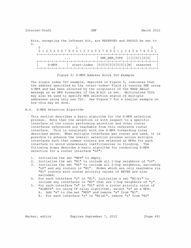
Internet-Draft SMF March 2012
bits, excepting the leftmost bit, are RESERVED and SHOULD be set to 0. 0 1 2 3 0 1 2 3 4 5 6 7 8 9 0 1 2 3 4 5 6 7 8 9 0 1 2 3 4 5 6 7 8 9 0 1 +-+-+-+-+-+-+-+-+-+-+-+-+-+-+-+-+-+-+-+-+-+-+-+-+-+-+-+-+-+-+-+-+ ... | SMF_NBR_TYPE |1|1|0|1|0|0| | +-+-+-+-+-+-+-+-+-+-+-+-+-+-+-+-+-+-+-+-+-+-+-+-+-+-+-+-+-+-+-+-+ | S-MPR | start-index |0|0|0|0|0|0|0|1|M| reserved | +-+-+-+-+-+-+-+-+-+-+-+-+-+-+-+-+-+-+-+-+-+-+-+-+-+-+-+-+-+-+-+-+
Figure 9: S-MPR Address Block TLV Example
The single index TLV example, depicted in Figure 9, indicates that the address specified by the <start-index> field is running SMF using S-MPR and has been selected by the originator of the NHDP HELLO message as an MPR forwarder if the M bit is set. Multivalued TLVs may also be used to specify MPR selection status of multiple addresses using only one TLV. See Figure 7 for a similar example on how this may be done.
B.4. S-MPR Selection Algorithm
This section describes a basic algorithm for the S-MPR selection process. Note that the selection is with respect to a specific interface of the router performing selection and other router interfaces referenced are reachable from this reference router interface. This is consistent with the S-MPR forwarding rules described above. When multiple interfaces per router are used, it is possible to enhance the overall selection process across multiple interfaces such that common routers are selected as MPRs for each interface to avoid unnecessary inefficiencies in flooding. The following steps describe a basic algorithm for conducting S-MPR selection for a router interface "n0":
1. Initialize the set "MPR" to empty. 2. Initialize the set "N1" to include all 1-hop neighbors of "n0". 3. Initialize the set "N2" to include all 2-hop neighbors, excluding "n0" and any routers in "N1". Nodes which are only reachable via "N1" routers with router priority values of NEVER are also excluded. 4. For each interface "y" in "N1", initialize a set "N2(y)" to include any interfaces in "N2" that are 1-hop neighbors of "y". 5. For each interface "x" in "N1" with a router priority value of "ALWAYS" (or using CF relay algorithm), select "x" as a MPR: A. Add "x" to the set "MPR" and remove "x" from "N1". B. For each interface "z" in "N2(x)", remove "z" from "N2"
Macker, editor Expires September 7, 2012 [Page 49]
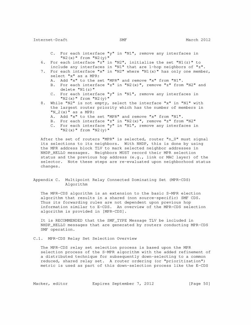
Internet-Draft SMF March 2012
C. For each interface "y" in "N1", remove any interfaces in "N2(x)" from "N2(y)" 6. For each interface "z" in "N2", initialize the set "N1(z)" to include any interfaces in "N1" that are 1-hop neighbors of "z". 7. For each interface "x" in "N2" where "N1(x)" has only one member, select "x" as a MPR: A. Add "x" to the set "MPR" and remove "x" from "N1". B. For each interface "z" in "N2(x)", remove "z" from "N2" and delete "N1(z)" C. For each interface "y" in "N1", remove any interfaces in "N2(x)" from "N2(y)" 8. While "N2" is not empty, select the interface "x" in "N1" with the largest router priority which has the number of members in "N_2(x)" as a MPR: A. Add "x" to the set "MPR" and remove "x" from "N1". B. For each interface "z" in "N2(x)", remove "z" from "N2" C. For each interface "y" in "N1", remove any interfaces in "N2(x)" from "N2(y)"
After the set of routers "MPR" is selected, router "n_0" must signal its selections to its neighbors. With NHDP, this is done by using the MPR address block TLV to mark selected neighbor addresses in NHDP_HELLO messages. Neighbors MUST record their MPR selection status and the previous hop address (e.g., link or MAC layer) of the selector. Note these steps are re-evaluated upon neighborhood status changes.
Appendix C. Multipoint Relay Connected Dominating Set (MPR-CDS) Algorithm
The MPR-CDS algorithm is an extension to the basic S-MPR election algorithm that results in a shared (non source-specific) SMF CDS. Thus its forwarding rules are not dependent upon previous hop information similar to E-CDS. An overview of the MPR-CDS selection algorithm is provided in [MPR-CDS].
It is RECOMMENDED that the SMF_TYPE Message TLV be included in NHDP_HELLO messages that are generated by routers conducting MPR-CDS SMF operation.
C.1. MPR-CDS Relay Set Selection Overview
The MPR-CDS relay set selection process is based upon the MPR selection process of the S-MPR algorithm with the added refinement of a distributed technique for subsequently down-selecting to a common reduced, shared relay set. A router ordering (or "prioritization") metric is used as part of this down-selection process like the E-CDS
Macker, editor Expires September 7, 2012 [Page 50]
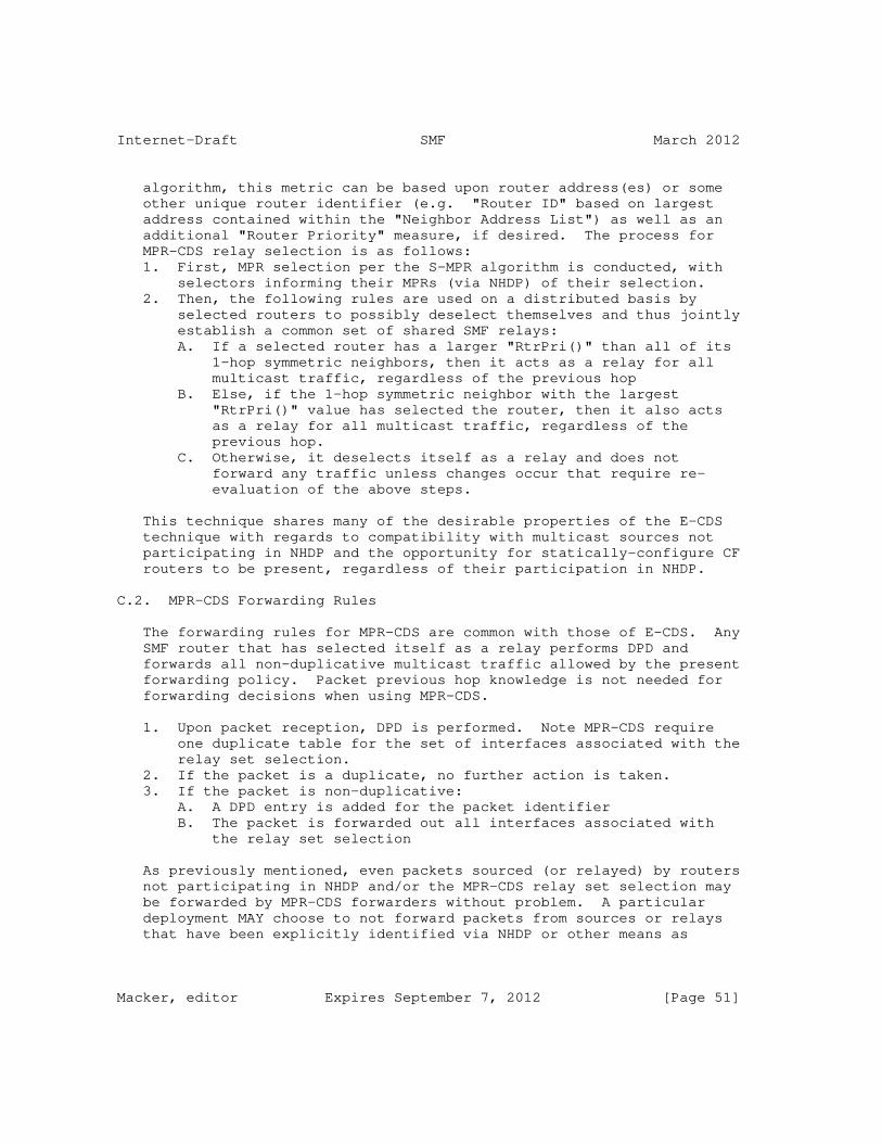
Internet-Draft SMF March 2012
algorithm, this metric can be based upon router address(es) or some other unique router identifier (e.g. "Router ID" based on largest address contained within the "Neighbor Address List") as well as an additional "Router Priority" measure, if desired. The process for MPR-CDS relay selection is as follows: 1. First, MPR selection per the S-MPR algorithm is conducted, with selectors informing their MPRs (via NHDP) of their selection. 2. Then, the following rules are used on a distributed basis by selected routers to possibly deselect themselves and thus jointly establish a common set of shared SMF relays: A. If a selected router has a larger "RtrPri()" than all of its 1-hop symmetric neighbors, then it acts as a relay for all multicast traffic, regardless of the previous hop B. Else, if the 1-hop symmetric neighbor with the largest "RtrPri()" value has selected the router, then it also acts as a relay for all multicast traffic, regardless of the previous hop. C. Otherwise, it deselects itself as a relay and does not forward any traffic unless changes occur that require re- evaluation of the above steps.
This technique shares many of the desirable properties of the E-CDS technique with regards to compatibility with multicast sources not participating in NHDP and the opportunity for statically-configure CF routers to be present, regardless of their participation in NHDP.
C.2. MPR-CDS Forwarding Rules
The forwarding rules for MPR-CDS are common with those of E-CDS. Any SMF router that has selected itself as a relay performs DPD and forwards all non-duplicative multicast traffic allowed by the present forwarding policy. Packet previous hop knowledge is not needed for forwarding decisions when using MPR-CDS.
1. Upon packet reception, DPD is performed. Note MPR-CDS require one duplicate table for the set of interfaces associated with the relay set selection. 2. If the packet is a duplicate, no further action is taken. 3. If the packet is non-duplicative: A. A DPD entry is added for the packet identifier B. The packet is forwarded out all interfaces associated with the relay set selection
As previously mentioned, even packets sourced (or relayed) by routers not participating in NHDP and/or the MPR-CDS relay set selection may be forwarded by MPR-CDS forwarders without problem. A particular deployment MAY choose to not forward packets from sources or relays that have been explicitly identified via NHDP or other means as
Macker, editor Expires September 7, 2012 [Page 51]

Internet-Draft SMF March 2012
operating as part of a different relay set algorithm (e.g. S-MPR) to allow coexistent deployments to operate correctly.
C.3. MPR-CDS Neighborhood Discovery Requirements
The neighborhood discovery requirements for MPR-CDS have commonality with both the S-MPR and E-CDS algorithms. MPR-CDS selection operation requires 2-hop neighbor knowledge as provided by NHDP [RFC6130] or from external sources. Unlike S-MPR operation, there is no need for associating link-layer address information with 1-hop neighbors since MPR-CDS forwarding is independent of the previous hop similar to E-CDS forwarding.
To advertise an optional "Router Priority" value or "WILLINGNESS" an originating router may use the Message TLV of type SMF_TYPE:MPR-CDS which shares a common <value> format with both SMF_TYPE:E-CDS Table 14 and SMF_TYPE:S-MPR Table 16.
MPR-CDS only requires 1-hop knowledge of "Router Priority" for correct operation. In the S-MPR phase of MPR-CDS selection, MPRs are dynamically determined by each router and selections MUST be advertised and dynamically updated using NHDP or an equivalent protocol or mechanism. The <value> field of the SMF_NBR_TYPE:MPR-CDS type TLV shares a common format with SMF_NBR_TYPE:S-MPR Table 17 to convey MPR selection.
C.4. MPR-CDS Selection Algorithm
This section describes an algorithm for the MPR-CDS selection process. Note that the selection described is with respect to a specific interface of the router performing selection and other router interfaces referenced are reachable from this reference router interface. An ordered tuple of "Router Priority" and "Router ID" is used in MPR-CDS relay set selection. The "Router ID" value should be set to the largest advertised address of a given router, this information is provided to one hop neighbors via NHDP by default. Precedence is given to the "Router Priority" portion and the "Router ID" value is used as a tie-breaker. The evaluation of this tuple is referred to as "RtrPri(n)" in the description below where "n" references a specific router. Note it is possible that the "Router Priority" portion may be optional and the evaluation of "RtrPri()" be solely based upon the unique "Router ID". Since there MUST NOT be any duplicate address values among SMF routers, a comparison of RtrPri(n) between any two routers will always be an inequality. The following steps, repeated upon any changes detected within the 1-hop and 2-hop neighborhood, describe a basic algorithm for conducting MPR-CDS selection for a router interface "n0":
Macker, editor Expires September 7, 2012 [Page 52]

Internet-Draft SMF March 2012
1. Perform steps 1-8 of Appendix B.4 to select MPRs from the set of 1-hop neighbors of "n0" and notify/update neighbors of selections. 2. Upon being selected as an MPR (or any change in the set of routers selecting "n0" as an MPR): A. If no neighbors have selected "n0" as an MPR, "n0" does not act as a relay and no further steps are taken until a change in neighborhood topology or selection status occurs. B. Determine the router "n1_max" that has the maximum "RtrPri()" of all 1-hop neighbors. C. If "RtrPri(n0)" is greater than "RtrPri(n1_max)", then "n0" selects itself as a relay for all multicast packets, D. Else, if "n1_max" has selected "n0" as an MPR, then "0" selects itself as a relay for all multicast packets. E. Otherwise, "n0" does not act as a relay.
It is possible to extend this algorithm to consider neighboring SMF routers that are known to be statically configured for CF (always relaying). The modification to the above algorithm is to process such routers as having a maximum possible "Router Priority" value. This is the same as the case for participating routers that have been configured with a S-MPR "WILLINGNESS" value of "WILL_ALWAYS". It is expected that routers configured for CF and participating in NHDP would indicate their status with use of the SMF_TYPE TLV type in their NHDP_HELLO message TLV block. It is important to note however that CF routers will not select MPR routers and therefore cannot guarantee connectedness.
Author’s Address
Joseph Macker NRL Washington, DC 20375 USA
Email: [email protected]
Macker, editor Expires September 7, 2012 [Page 53]

Internet Engineering Task Force R. ColeInternet-Draft US Army CERDECIntended status: Experimental J. MackerExpires: April 4, 2012 B. Adamson Naval Research Laboratory S. Harnedy Booz Allen Hamilton October 2, 2011
Definition of Managed Objects for the Manet Simplified Multicast Framework Relay Set Process draft-ietf-manet-smf-mib-03
Abstract
This memo defines a portion of the Management Information Base (MIB) for use with network management protocols in the Internet community. In particular, it describes objects for configuring aspects of the Simplified Multicast Forwarding (SMF) process for Mobile Ad-Hoc Networks (MANETs). The SMF-MIB also reports state information, performance metrics, and notifications. In addition to configuration, the additional state and performance information is useful to operators troubleshooting multicast forwarding problems.
Status of This Memo
This Internet-Draft is submitted in full conformance with the provisions of BCP 78 and BCP 79.
Internet-Drafts are working documents of the Internet Engineering Task Force (IETF). Note that other groups may also distribute working documents as Internet-Drafts. The list of current Internet- Drafts is at http://datatracker.ietf.org/drafts/current/.
Internet-Drafts are draft documents valid for a maximum of six months and may be updated, replaced, or obsoleted by other documents at any time. It is inappropriate to use Internet-Drafts as reference material or to cite them other than as "work in progress."
This Internet-Draft will expire on April 4, 2012.
Copyright Notice
Copyright (c) 2011 IETF Trust and the persons identified as the document authors. All rights reserved.
This document is subject to BCP 78 and the IETF Trust’s Legal
Cole, et al. Expires April 4, 2012 [Page 1]

Internet-Draft The SMF MIB October 2011
Provisions Relating to IETF Documents (http://trustee.ietf.org/license-info) in effect on the date of publication of this document. Please review these documents carefully, as they describe your rights and restrictions with respect to this document. Code Components extracted from this document must include Simplified BSD License text as described in Section 4.e of the Trust Legal Provisions and are provided without warranty as described in the Simplified BSD License.
Table of Contents
1. Introduction . . . . . . . . . . . . . . . . . . . . . . . . . 3 2. The Internet-Standard Management Framework . . . . . . . . . . 3 3. Conventions . . . . . . . . . . . . . . . . . . . . . . . . . 3 4. Overview . . . . . . . . . . . . . . . . . . . . . . . . . . . 3 4.1. SMF Management Model . . . . . . . . . . . . . . . . . . . 4 4.2. Terms . . . . . . . . . . . . . . . . . . . . . . . . . . 5 5. Structure of the MIB Module . . . . . . . . . . . . . . . . . 5 5.1. Textual Conventions . . . . . . . . . . . . . . . . . . . 6 5.2. The Capabilities Group . . . . . . . . . . . . . . . . . . 6 5.3. The Configuration Group . . . . . . . . . . . . . . . . . 7 5.4. The State Group . . . . . . . . . . . . . . . . . . . . . 7 5.5. The Performance Group . . . . . . . . . . . . . . . . . . 7 5.6. The Notifications Group . . . . . . . . . . . . . . . . . 8 6. Relationship to Other MIB Modules . . . . . . . . . . . . . . 8 6.1. Relationship to the SNMPv2-MIB . . . . . . . . . . . . . . 8 6.2. MIB modules required for IMPORTS . . . . . . . . . . . . . 8 6.3. Relationship to the Future RSSA-MIBs . . . . . . . . . . . 8 7. Definitions . . . . . . . . . . . . . . . . . . . . . . . . . 9 8. Security Considerations . . . . . . . . . . . . . . . . . . . 48 9. IANA Considerations . . . . . . . . . . . . . . . . . . . . . 51 10. Contributors . . . . . . . . . . . . . . . . . . . . . . . . . 52 11. References . . . . . . . . . . . . . . . . . . . . . . . . . . 52 11.1. Normative References . . . . . . . . . . . . . . . . . . . 52 11.2. Informative References . . . . . . . . . . . . . . . . . . 53 Appendix A. Change Log . . . . . . . . . . . . . . . . . . . . . 53 Appendix B. Open Issues . . . . . . . . . . . . . . . . . . . . . 54 Appendix C. . . . . . . . . . . . . . . . . . . . . . . . . . . 54
Cole, et al. Expires April 4, 2012 [Page 2]

Internet-Draft The SMF MIB October 2011
1. Introduction
This memo defines a portion of the Management Information Base (MIB) for use with network management protocols in the Internet community. In particular, it describes objects for configuring aspects of a process implementing Simplified Multicast Forwarding (SMF) [I-D.ietf-manet-smf] for Mobile Ad-Hoc Networks (MANETs). SMF provides multicast Duplicate Packet Detection (DPD) and supports algorithms for constructing an estimate of a MANET Minimum Connected Dominating Set (MCDS) for efficient multicast forwarding. The SMF- MIB also reports state information, performance metrics, and notifications. In addition to configuration, this additional state and performance information is useful to operators troubleshooting multicast forwarding problems.
2. The Internet-Standard Management Framework
For a detailed overview of the documents that describe the current Internet-Standard Management Framework, please refer to section 7 of RFC 3410 [RFC3410].
Managed objects are accessed via a virtual information store, termed the Management Information Base or MIB. MIB objects are generally accessed through the Simple Network Management Protocol (SNMP). Objects in the MIB are defined using the mechanisms defined in the Structure of Management Information (SMI). This memo specifies a MIB module that is compliant to the SMIv2, which is described in STD 58, RFC 2578 [RFC2578], STD 58, RFC 2579 [RFC2579] and STD 58, RFC 2580 [RFC2580].
3. Conventions
The key words "MUST", "MUST NOT", "REQUIRED", "SHALL", "SHALL NOT", "SHOULD", "SHOULD NOT", "RECOMMENDED", "MAY", and "OPTIONAL" in this document are to be interpreted as described in RFC 2119 [RFC2119].
4. Overview
SMF provides methods for implementing DPD-based multicast forwarding with the optional use of Connected Dominating Set (CDS)-based relay sets. The CDS provides a complete connected coverage of the nodes comprising the MANET. The MCDS is the smallest set of MANET nodes (comprising a connected cluster) which cover all the nodes in the cluster with their transmissions. As the density of the MANET nodes increase, the fraction of nodes required in an MCDS decreases. Using the MCDS as a multicast forwarding set then becomes an efficient multicast mechanism for MANETs.
Cole, et al. Expires April 4, 2012 [Page 3]

Internet-Draft The SMF MIB October 2011
Various algorithms for the construction of estimates of the MCDS exist. The Simplified Multicast Framework [I-D.ietf-manet-smf] describes some of these. It further defines various operational modes for a node which is participating in the collective creation of the MCDS estimates. These modes depend upon the set of related MANET routing and discovery protocols and mechanisms in operation in the specific MANET node.
A SMF router’s MIB contains SMF process configuration parameters (e.g. specific CDS algorithm), state information (e.g., current membership in the CDS), performance counters (e.g., packet counters), and notifications.
4.1. SMF Management Model
This section describes the management model for the SMF node process.
Figure 1 (reproduced from Figure 4 of [I-D.ietf-manet-smf]) shows the relationship between the SMF Relay Set selection algorithm and the related algorithms, processes and protocols running in the MANET nodes. The Relay Set Selection Algorithm (RSSA) can rely upon topology information gotten from the MANET Neighborhood Discovery Protocol (NHDP), from the specific MANET routing protocol running on the node, or from Layer 2 information passed up to the higher layer protocol processes.
Cole, et al. Expires April 4, 2012 [Page 4]

Internet-Draft The SMF MIB October 2011
______________ ____________ | | | | | Neighborhood | | Relay Set | | Discovery |------------->| Selection | | Protocol | neighbor | Algorithm | |______________| info |____________| \ / \ / neighbor\ / forwarding info* \ _____________ / status \ | | / ‘-->| Forwarding |<--’ | Process | ----------------->|_____________|-----------------> incoming packet, forwarded packets interface id*, and previous hop*
Figure 1: SMF Node Architecture
4.2. Terms
The following definitions apply throughout this document:
o Configuration Objects - switches, tables, objects which are initialized to default settings or set through the management interface defined by this MIB.
o Tunable Configuration Objects - objects whose values affect timing or attempt bounds on the SMF RS process.
o State Objects - automatically generated values which define the current operating state of the SMF RS process in the router.
o Performance Objects - automatically generated values which help an administrator or automated tool to assess the performance of the CDS multicast process on the router and the overall multicasting performance within the MANET routing domain.
5. Structure of the MIB Module
This section presents the structure of the SMF-MIB module. The objects are arranged into the following groups:
o smfMIBNotifications - defines the notifications associated with the SMF-MIB.
Cole, et al. Expires April 4, 2012 [Page 5]

Internet-Draft The SMF MIB October 2011
o smfMIBObjects - defines the objects forming the basis for the SMF- MIB. These objects are divided up by function into the following groups:
o
* Capabilities Group - This group contains the SMF objects that the device uses to advertise its local capabilities with respect to, e.g., the supported RSSAs.
* Configuration Group - This group contains the SMF objects that configure specific options that determine the overall operation of the SMF RSSA and the resulting multicast performance.
* State Group - Contains information describing the current state of the SMF RSSA process such as the Neighbor Table.
* Performance Group - Contains objects which help to characterize the performance of the SMF RSSA process, typically statistics counters.
o smfMIBConformance - defines minimal and full conformance of implementations to this SMF-MIB.
5.1. Textual Conventions
The textual conventions defined within the SMF-MIB are as follows:
o The SmfStatus is defined within the SMF-MIB. This contains the current operational status of the SMF process on an interface.
o The SmfOpModeID represents an index that identifies a specific SMF operational mode.
o The SmfRssaID represents an index that identifies, through reference, a specific RSSA available for operation on the device.
5.2. The Capabilities Group
The SMF device supports a set of capabilities. The list of capabilities which the device can advertise are:
o Operational Mode - topology information from NHDP, CDS-aware unicast routing or Cross-layer from Layer 2.
o SMF RSSA - the specific RSSA operational on the device. Note that configuration, state and performance objects related to a specific RSSA must be defined within another separate MIB.
Cole, et al. Expires April 4, 2012 [Page 6]

Internet-Draft The SMF MIB October 2011
5.3. The Configuration Group
The SMF device is configured with a set of controls. Some of the prominent configuration controls for the SMF device follow:
o Operational Mode - topology information from NHDP, CDS-aware unicast routing or Cross-layer from Layer 2.
o SMF RSSA - the specific RSSA operational on the device.
o Duplicate Packet detection for IPv4 - Identification-based or Hash-based DPD.
o Duplicate Packet detection for IPv6 - Identification-based or Hash-based DPD.
o SMF Type Message TLV - if NHDP mode is selected, then is the SMF Type Message TLV may be included in the NHDP exchanges.
o SMF Address Block TLV - if NHDP mode is selected, then is the SMF Address Block TLV should be included in the NHDP exchanges.
5.4. The State Group
The State Subtree reports current state information, e.g.,
o Node RSS State - is the node currently in or out of the Relay Set.
o Neighbors Table - a table containing current neighbors and their operational RSSA.
5.5. The Performance Group
The Performance subtree reports primarily counters that relate to SMF RSSA performance. The SMF performance counters consists of per node and per interface objects:
o Total multicast packets received.
o Total multicast packets forwarded.
o Total duplicate multicast packets detected.
o Per interface statistics table with the following entries:
o
Cole, et al. Expires April 4, 2012 [Page 7]

Internet-Draft The SMF MIB October 2011
* Multicast packets received.
* Multicast packets forwarded.
* Duplicate multicast packets detected.
5.6. The Notifications Group
The Notifications Subtree contains the list of notifications supported within the SMF-MIB and their intended purpose or utility.
6. Relationship to Other MIB Modules
6.1. Relationship to the SNMPv2-MIB
The ’system’ group in the SNMPv2-MIB [RFC3418] is defined as being mandatory for all systems, and the objects apply to the entity as a whole. The ’system’ group provides identification of the management entity and certain other system-wide data. The SMF-MIB does not duplicate those objects.
6.2. MIB modules required for IMPORTS
The textual conventions imported for use in the SMF-MIB are as follows. The MODULE-IDENTITY, OBJECT-TYPE, NOTIFICATION-TYPE, Counter32, Unsigned32, Integer32 and mib-2 textual conventions are imported from RFC 2578 [RFC2578]. The TEXTUAL-CONVENTION, RowStatus and TruthValue textual conventions are imported from RFC 2579 [RFC2579]. The MODULE-COMPLIANCE, OBJECT-GROUP and NOTIFICATION- GROUP textual conventions are imported from RFC 2580 [RFC2580]. The InterfaceIndexOrZero textual convention is imported from RFC 2863 [RFC2863]. The SnmpAdminString textual convention is imported from RFC 3411 [RFC3411]. The InetAddress, InetAddressType and InetAddressPrefixLength textual conventions are imported from RFC 4001 [RFC4001].
6.3. Relationship to the Future RSSA-MIBs
In a sense, the SMF-MIB is a general front-end to a set of, yet to be developed, RSSA-specific MIBs. These RSSA-specific MIBs will define the objects for the configuration, state, performance and notification objects required for the operation of these specific RSSAs. The SMF-MIB Capabilities Group allows the remote management station the ability to query the router to discover the set of supported RSSAs.
Cole, et al. Expires April 4, 2012 [Page 8]

Internet-Draft The SMF MIB October 2011
7. Definitions
MANET-SMF-MIB DEFINITIONS ::= BEGIN
IMPORTS
MODULE-IDENTITY, OBJECT-TYPE, NOTIFICATION-TYPE, Counter32, Integer32, TimeTicks, experimental FROM SNMPv2-SMI -- [RFC2578]
TEXTUAL-CONVENTION, RowStatus, TruthValue FROM SNMPv2-TC -- [RFC2579]
MODULE-COMPLIANCE, OBJECT-GROUP, NOTIFICATION-GROUP FROM SNMPv2-CONF -- [RFC2580]
InterfaceIndexOrZero FROM IF-MIB -- [RFC2863]
SnmpAdminString FROM SNMP-FRAMEWORK-MIB -- [RFC3411]
InetAddress, InetAddressType, InetAddressPrefixLength FROM INET-ADDRESS-MIB -- [RFC4001] ;
manetSmfMIB MODULE-IDENTITY LAST-UPDATED "201110021300Z" -- October 02, 2011 ORGANIZATION "IETF MANET Working Group" CONTACT-INFO "WG E-Mail: [email protected]
WG Chairs: [email protected] [email protected]
Editors: Robert G. Cole US Army CERDEC Space and Terrestrial Communications 6010 Frankford Road Aberdeen Proving Ground, MD 21005 USA +1 443 395-8744 [email protected]
Cole, et al. Expires April 4, 2012 [Page 9]

Internet-Draft The SMF MIB October 2011
http://www.cs.jhu.edu/˜rgcole/
Joseph Macker Naval Research Laboratory Washington, D.C. 20375 USA [email protected]
Brian Adamson Naval Research Laboratory Washington, D.C. 20375 USA [email protected]
Sean Harnedy Booz Allen Hamilton 333 City Boulevard West Orange, CA 92868 USA +1 714 938-3898 [email protected]"
DESCRIPTION "This MIB module contains managed object definitions for the Manet SMF RSSA process defined in:
[SMF] Macker, J.(ed.), Simplified Multicast Forwarding draft-ietf-manet-smf-10, March 06, 2010.
Copyright (C) The IETF Trust (2008). This version of this MIB module is part of RFC xxxx; see the RFC itself for full legal notices."
-- Revision History REVISION "201110021300Z" -- October 02, 2011 DESCRIPTION "Updated 6th revision of the draft of this MIB module published as draft-ietf-manet-smf-mib-03.txt. The changes made in this revision include: - Added some notes to the MIB module - Clarified and defined default settings " REVISION "201101161300Z" -- January 16, 2011 DESCRIPTION "Updated 5th revision of the draft of this MIB module published as
Cole, et al. Expires April 4, 2012 [Page 10]

Internet-Draft The SMF MIB October 2011
draft-ietf-manet-smf-mib-02.txt. The changes made in this revision include: - Added the Notification Group and cleaned up the Conformance section - Completed the TEXTUAL CONVENTION for the smfOpMode. - Completed the Description clauses of several objects within the MIB. - Removed the routerPriority object. - Added the definition of a smfRouterID object and associated smfRouterIDAddrType object. " REVISION "200910261300Z" -- October 26, 2009 DESCRIPTION "Updated draft of this MIB module published as draft-ietf-manet-smf-mib-01.txt. A few changes were made in the development of this draft. Specifically, the following changes were made: - Updated the textual material, included section on IMPORTS, relationship to other MIBs, etc. " REVISION "200904211300Z" -- April 21, 2009 DESCRIPTION "Updated draft of this MIB module published as draft-ietf-manet-smf-mib-00.txt. A few changes were made in the development of this draft. Specifically, the following changes were made: - Removed the smfGatewayFilterTable from this draft. It is a useful construct, e.g., an IPTABLES-MIB, but might best be handled as a seperate MIB and worked within a security focused working group. - Removed the smfReportsGroup. This capability is being replaced with a new and more general method for offline reporting. This is being worked as a new MIB module refered to as the REPORT-MIB. - Rev’d as a new MANET WG document. " REVISION "200902271300Z" -- February 27, 2009 DESCRIPTION "Updated draft of this MIB module published as draft-cole-manet-smf-mib-02.txt. Fairly extensive revisions and additions to this MIB were made in this version. Specifically, the following changes were made in development of this version:
Cole, et al. Expires April 4, 2012 [Page 11]

Internet-Draft The SMF MIB October 2011
- added a Capabilities Group within the Objects Group to allow the device to report supported capabilities, e.g., RSSAs supported. - added administrative status objects for device and interfaces - added multicast address forwarding tables, both for configured (within Configuration Group) and discovered (within the State Group). - added additional Performance counters related to DPD functions. - Split up the performance counters into IPv4 and IPv6, for both global and per interface statistics. - Split out the reports capability into a seperate Reports Group under the Objects Group. " REVISION "200811031300Z" -- November 03, 2008 DESCRIPTION "Updated draft of this MIB module published as draft-cole-manet-smf-mib-01.txt. Added gateway filter table and reports capabilities following rmon." REVISION "200807071200Z" -- July 07, 2008 DESCRIPTION "Initial draft of this MIB module published as draft-cole-manet-smf-mib-00.txt." -- RFC-Editor assigns XXXX ::= { experimental 998 } -- to be assigned by IANA
-- -- TEXTUAL CONVENTIONs --
SmfStatus ::= TEXTUAL-CONVENTION STATUS current DESCRIPTION "An indication of the operability of a SMF function or feature. For example, the status of an interface: ’enabled’ indicates that it is performing SMF functions, and ’disabled’ indicates that it is not." SYNTAX INTEGER { enabled (1), disabled (2) }
SmfOpModeID ::= TEXTUAL-CONVENTION
Cole, et al. Expires April 4, 2012 [Page 12]

Internet-Draft The SMF MIB October 2011
STATUS current DESCRIPTION "An index that identifies through reference to a specific SMF operations mode. There are basically three styles of SMF operation with reduced relay sets:
Independent operation - SMF performs its own relay set selection using information from an associated MANET NHDP process.
CDS-aware unicast routing operation - a coexistent unicast routing protocol provides dynamic relay set state based upon its own control plane CDS or neighborhood discovery information.
Cross-layer operation - SMF operates using neighborhood status and triggers from a cross-layer information base for dynamic relay set selection and maintenance " SYNTAX INTEGER { independent (1), routing (2), crossLayer (3) -- future (4-255) }
SmfRssaID ::= TEXTUAL-CONVENTION STATUS current DESCRIPTION "An index that identifies through reference to a specific RSSA algorithms. Several are currently defined in the appendix of " SYNTAX INTEGER { cF(1), sMPR(2), eCDS(3), mprCDS(4) -- future(5-127) -- noStdAction(128-239) -- experimental(240-255) }
-- -- Top-Level Object Identifier Assignments
Cole, et al. Expires April 4, 2012 [Page 13]

Internet-Draft The SMF MIB October 2011
--
smfMIBNotifications OBJECT IDENTIFIER ::= { manetSmfMIB 0 } smfMIBObjects OBJECT IDENTIFIER ::= { manetSmfMIB 1 } smfMIBConformance OBJECT IDENTIFIER ::= { manetSmfMIB 2 }
-- -- smfMIBObjects Assignments: -- smfCapabilitiesGroup - 1 -- smfConfigurationGroup - 2 -- smfStateGroup - 3 -- smfPerformanceGroup - 4 --
-- -- smfCapabilitiesGroup -- -- This group contains the SMF objects that identify specific -- capabilities within this device related to SMF functions. --
smfCapabilitiesGroup OBJECT IDENTIFIER ::= { smfMIBObjects 1 }
-- -- SMF Operational Mode Capabilities Table --
smfOpModeCapabilitiesTable OBJECT-TYPE SYNTAX SEQUENCE OF SmfOpModeCapabilitiesEntry MAX-ACCESS not-accessible STATUS current DESCRIPTION "The smfOpModeCapabilitiesTable identifies the resident set of SMF Operational Modes on this router. " ::= { smfCapabilitiesGroup 1 }
smfOpModeCapabilitiesEntry OBJECT-TYPE SYNTAX SmfOpModeCapabilitiesEntry MAX-ACCESS not-accessible STATUS current DESCRIPTION "Information about a particular operational mode. "
Cole, et al. Expires April 4, 2012 [Page 14]

Internet-Draft The SMF MIB October 2011
INDEX { smfOpModeCapabilitiesID } ::= { smfOpModeCapabilitiesTable 1 }
SmfOpModeCapabilitiesEntry ::= SEQUENCE { smfOpModeCapabilitiesID SmfOpModeID, smfOpModeCapabilitiesName SnmpAdminString, smfOpModeCapabilitiesReference SnmpAdminString }
smfOpModeCapabilitiesID OBJECT-TYPE SYNTAX SmfOpModeID MAX-ACCESS not-accessible STATUS current DESCRIPTION "The index for this entry. This object identifies the particular operational mode for this device. " ::= { smfOpModeCapabilitiesEntry 1 }
smfOpModeCapabilitiesName OBJECT-TYPE SYNTAX SnmpAdminString MAX-ACCESS read-only STATUS current DESCRIPTION "The textual name of this operational mode. Current operational modes include: Independent Mode, CDS-aware Routing Mode, and Cross-layer Mode. Others may be defined in future revisions of [SMF]. " ::= { smfOpModeCapabilitiesEntry 2 }
smfOpModeCapabilitiesReference OBJECT-TYPE SYNTAX SnmpAdminString MAX-ACCESS read-only STATUS current DESCRIPTION "This object contains a reference to the document that defines this operational mode. " ::= { smfOpModeCapabilitiesEntry 3 }
-- -- SMF RSSA Capabilities Table --
smfRssaCapabilitiesTable OBJECT-TYPE
Cole, et al. Expires April 4, 2012 [Page 15]

Internet-Draft The SMF MIB October 2011
SYNTAX SEQUENCE OF SmfRssaCapabilitiesEntry MAX-ACCESS not-accessible STATUS current DESCRIPTION "The smfRssaCapabilitiesTable contains reference to the specific set of RSSAs currently supported on this device. " ::= { smfCapabilitiesGroup 2 }
smfRssaCapabilitiesEntry OBJECT-TYPE SYNTAX SmfRssaCapabilitiesEntry MAX-ACCESS not-accessible STATUS current DESCRIPTION "Information about a particular RSSA algorithm." INDEX { smfRssaCapabilitiesID } ::= { smfRssaCapabilitiesTable 1 }
SmfRssaCapabilitiesEntry ::= SEQUENCE { smfRssaCapabilitiesID SmfRssaID, smfRssaCapabilitiesName SnmpAdminString, smfRssaCapabilitiesReference SnmpAdminString }
smfRssaCapabilitiesID OBJECT-TYPE SYNTAX SmfRssaID MAX-ACCESS not-accessible STATUS current DESCRIPTION "The index for this entry. This object identifies the particular RSSA algorithm in this MIB module. Example RSSAs are found in the appendix of [SMF]. The default for this is the Classical Flooding algorithm. All compliant SMF forwarders must support Classical Flooding. Hence, at least one entry in this table must exist with a smfRssaCapabilitiesID of ’1’." DEFVAL { 1 } ::= { smfRssaCapabilitiesEntry 1 }
smfRssaCapabilitiesName OBJECT-TYPE SYNTAX SnmpAdminString MAX-ACCESS read-only STATUS current DESCRIPTION "The textual name of this RSSA algorithm.
Cole, et al. Expires April 4, 2012 [Page 16]

Internet-Draft The SMF MIB October 2011
Currently defined names are: Classical Flooding - cF, Source-based MultiPoint Relay - sMPR, Essential Connecting Dominating Set - eCDS, MultiPoint Relay Connected Dominating Set - mprCDS. " ::= { smfRssaCapabilitiesEntry 2 }
smfRssaCapabilitiesReference OBJECT-TYPE SYNTAX SnmpAdminString MAX-ACCESS read-only STATUS current DESCRIPTION "This object contains a published reference to the document that defines this algorithm. " ::= { smfRssaCapabilitiesEntry 3 }
-- -- smfConfigurationGroup -- -- This group contains the SMF objects that configure specific -- options that determine the overall performance and operation -- of the multicast forwarding process for the router device -- and its interfaces. --
smfConfigurationGroup OBJECT IDENTIFIER ::= { smfMIBObjects 2 }
smfAdminStatus OBJECT-TYPE SYNTAX SmfStatus MAX-ACCESS read-write STATUS current DESCRIPTION "The configured status of the SMF process on this device. Enabled(1) means that SMF is configured to run on this device. Disabled(2) mean that the SMF process is configured off.
This object is persistent and when written the entity SHOULD save the change to
Cole, et al. Expires April 4, 2012 [Page 17]

Internet-Draft The SMF MIB October 2011
non-volatile storage. " ::= { smfConfigurationGroup 1 }
smfRouterIDAddrType OBJECT-TYPE SYNTAX InetAddressType MAX-ACCESS read-write STATUS current DESCRIPTION "The address type of the address used for SMF ID of this router as specified in the ’smfRouterID’ next.
This can be set by the management station, the smfRouterID must be a routable address assigned to this router. If the management station does not assign this value, then the router should choose the highest routable IP address assigned to this router.
This object is persistent and when written the entity SHOULD save the change to non-volatile storage. " ::= { smfConfigurationGroup 2 }
smfRouterID OBJECT-TYPE SYNTAX InetAddress MAX-ACCESS read-write STATUS current DESCRIPTION "The IP address used as the SMF router ID. This can be set by the management station. If not explicitly set, then the device should select a routable IP address assigned to this router for use as the ’smfRouterID’.
The smfRouterID is a logical identification that MUST be consistent across interoperating SMF neighborhoods and it is RECOMMENDED to be chosen as the numerically largest address contained in a node’s ’Neighbor Address List’ as defined in NHDP. A smfRouterID MUST be unique within the scope of the operating MANET network regardless of the method used for selecting it.
Cole, et al. Expires April 4, 2012 [Page 18]

Internet-Draft The SMF MIB October 2011
This object is persistent and when written the entity SHOULD save the change to non-volatile storage. " ::= { smfConfigurationGroup 3 }
smfConfiguredOpMode OBJECT-TYPE SYNTAX INTEGER { withNHDP(1), cdsAwareRouting(2), crossLayer(3), other(4) } MAX-ACCESS read-write STATUS current DESCRIPTION "The SMF RSS node operational mode as defined in the TEXTUAL CONVENTION for ‘SmfOpModeID’ and in [SMF]..
The value withNHDP(1) indicates Independent Mode of operation.
The value cdsAwareRouting(2) indicates CDS-aware Routing Mode of operation.
The value crossLayer(3) indicates Cross-layer Mode of operation.
The default value for this object is withNHDP(1).
This object is persistent and when written the entity SHOULD save the change to non-volatile storage. " DEFVAL { 1 } ::= { smfConfigurationGroup 4 }
smfConfiguredRssa OBJECT-TYPE SYNTAX SmfRssaID MAX-ACCESS read-write STATUS current DESCRIPTION "The SMF RSS currently operational algorithm as defined in the TEXTUAL CONVENTION for ‘SmfRssaID’ and in [SMF].
Cole, et al. Expires April 4, 2012 [Page 19]

Internet-Draft The SMF MIB October 2011
The defluat value for this object is cF(1), i.e., Classical Flooding.
This object is persistent and when written the entity SHOULD save the change to non-volatile storage. " DEFVAL { 1 } ::= { smfConfigurationGroup 5 }
smfRssaMember OBJECT-TYPE SYNTAX INTEGER { potential(1), always(2), never(3) } MAX-ACCESS read-write STATUS current DESCRIPTION "The RSSA downselects a set of forwarders for multicast forwarding. Sometimes it is useful to force an agent to be included or excluded from the resulting RSS. This object is a switch to allow for this behavior.
The value potential(1) allows the selected RSSA to determine if this agent is included or excluded from the RSS.
The value always(1) forces the selected RSSA include this agent in the RSS.
The value never(3) forces the selected RSSA to exclude this agent from the RSS.
The default setting for this object is ’potential(1)’. Other settings could pose operational risks under certain conditions.
This object is persistent and when written the entity SHOULD save the change to non-volatile storage. " DEFVAL { 1 } ::= { smfConfigurationGroup 6 }
smfIpv4Dpd OBJECT-TYPE SYNTAX INTEGER {
Cole, et al. Expires April 4, 2012 [Page 20]

Internet-Draft The SMF MIB October 2011
hashBased(1), identificationBased(2) } MAX-ACCESS read-write STATUS current DESCRIPTION "The current method for IPv4 duplicate packet detection.
The value hashBased(1) indicates that the routers duplicate packet detection is based upon comparing a hash over the packet fields. This is the default setting for this object.
The value identificationBased(2) indicates that the duplicate packet detection relies upon header information in the multicast packets to identify previously received packets.
This object is persistent and when written the entity SHOULD save the change to non-volatile storage. " DEFVAL { 1 } ::= { smfConfigurationGroup 7 }
smfIpv6Dpd OBJECT-TYPE SYNTAX INTEGER { hashBased(1), identificationBased(2) } MAX-ACCESS read-write STATUS current DESCRIPTION "The current method for IPv6 duplicate packet detection.
The values indicate the type of method used for duplicate packet detection as described the previous description for the object ‘smfIpv4Dpd’.
The default value for this object is hashBased(1).
This object is persistent and when written the entity SHOULD save the change to
Cole, et al. Expires April 4, 2012 [Page 21]

Internet-Draft The SMF MIB October 2011
non-volatile storage. " DEFVAL { 1 } ::= { smfConfigurationGroup 8 }
smfMaxPktLifetime OBJECT-TYPE SYNTAX Integer32 (0..65535) UNITS "Seconds" MAX-ACCESS read-write STATUS current DESCRIPTION "The estimate of the network packet traversal time.
This object is persistent and when written the entity SHOULD save the change to non-volatile storage. " DEFVAL { 60 } ::= { smfConfigurationGroup 9 }
smfDpdMaxMemorySize OBJECT-TYPE SYNTAX Integer32 (0..65535) UNITS "Kilo-Bytes" MAX-ACCESS read-write STATUS current DESCRIPTION "The locally reserved memory for storage of cached DPD records for both IPv4 and IPv6 methods.
The local SMF device should protect itself against the SNMP manager from requesting too large a memory value. If this is the case, an error indication should be returned in response to the SNMP SET request.
This object is persistent and when written the entity SHOULD save the change to non-volatile storage. " DEFVAL { 1024 } ::= { smfConfigurationGroup 10 }
smfDpdEntryMaxLifetime OBJECT-TYPE SYNTAX Integer32 (0..65525) UNITS "Seconds" MAX-ACCESS read-write
Cole, et al. Expires April 4, 2012 [Page 22]

Internet-Draft The SMF MIB October 2011
STATUS current DESCRIPTION "The maximum lifetime of a cached DPD record in the local device storage.
If the memory is running low prior to the MaxLifetimes being exceeded, the local SMF devices should purge the oldest records first.
This object is persistent and when written the entity SHOULD save the change to non-volatile storage. " DEFVAL { 600 } ::= { smfConfigurationGroup 11 }
-- -- Configuration of messages to be included in -- NHDP message exchanges in support of SMF -- operations. --
smfNhdpRssaMesgTLVIncluded OBJECT-TYPE SYNTAX TruthValue MAX-ACCESS read-write STATUS current DESCRIPTION "Indicates whether the associated NHDP messages include the RSSA Message TLV, or not. This is an optional SMF operational setting. The value true(1) indicates that this TLV is included; the value false(2) indicates that it is not included.
It is RECOMMENDED that the RSSA Message TLV be included in the NHDP messages.
This object is persistent and when written the entity SHOULD save the change to non-volatile storage. " ::= { smfConfigurationGroup 12 }
smfNhdpRssaAddrBlockTLVIncluded OBJECT-TYPE SYNTAX TruthValue MAX-ACCESS read-write STATUS current
Cole, et al. Expires April 4, 2012 [Page 23]

Internet-Draft The SMF MIB October 2011
DESCRIPTION "Indicates whether the associated NHDP messages include the RSSA Address Block TLV, or not. This is an optional SMF operational setting. The value true(1) indicates that this TLV is included; the value false(2) indicates that it is not included.
The smfNhdpRssaAddrBlockTLVIncluded is optional in all cases as it depends on the existence of an address block which may not be present. If this SMF device is configured with NHDP, then this object should be set to ’true(1)’.
This object is persistent and when written the entity SHOULD save the change to non-volatile storage. " ::= { smfConfigurationGroup 13 }
-- -- Table identifying configured multicast addresses to be forwarded. --
smfConfiguredAddrForwardingTable OBJECT-TYPE SYNTAX SEQUENCE OF SmfConfiguredAddrForwardingEntry MAX-ACCESS not-accessible STATUS current DESCRIPTION "The (conceptual) table containing information on multicast addresses which are to be forwarded by the SMF process.
Entries in this table are configured. As well, addresses to be forwarded by the SMF device can be dynamically discovered by other means. The corresponding state table, smfDiscoveredAddrForwardingTable, contains these additional, dynamically discovered address for forwarding.
Each row is associated with a range of multicast addresses, and ranges for different rows must be disjoint.
The objects in this table are persistent and when written the entity SHOULD save the change to non-volatile storage. "
Cole, et al. Expires April 4, 2012 [Page 24]

Internet-Draft The SMF MIB October 2011
::= { smfConfigurationGroup 15 }
smfConfiguredAddrForwardingEntry OBJECT-TYPE SYNTAX SmfConfiguredAddrForwardingEntry MAX-ACCESS not-accessible STATUS current DESCRIPTION "An entry (conceptual row) containing the information on a particular multicast scope." INDEX { smfConfiguredAddrForwardingAddrType, smfConfiguredAddrForwardingFirstAddr } ::= { smfConfiguredAddrForwardingTable 1 }
SmfConfiguredAddrForwardingEntry ::= SEQUENCE { smfConfiguredAddrForwardingAddrType InetAddressType, smfConfiguredAddrForwardingFirstAddr InetAddress, smfConfiguredAddrForwardingLastAddr InetAddress, smfConfiguredAddrForwardingStatus RowStatus }
smfConfiguredAddrForwardingAddrType OBJECT-TYPE SYNTAX InetAddressType MAX-ACCESS not-accessible STATUS current DESCRIPTION "The type of the addresses in the multicast forwarding range. Legal values correspond to the subset of address families for which multicast address allocation is supported." ::= { smfConfiguredAddrForwardingEntry 1 }
smfConfiguredAddrForwardingFirstAddr OBJECT-TYPE SYNTAX InetAddress (SIZE(0..20)) MAX-ACCESS not-accessible STATUS current DESCRIPTION "The first address in the multicast scope range. The type of this address is determined by the value of the smfConfiguredAddrForwardingAddrType object." ::= { smfConfiguredAddrForwardingEntry 2 }
smfConfiguredAddrForwardingLastAddr OBJECT-TYPE SYNTAX InetAddress (SIZE(0..20)) MAX-ACCESS read-create STATUS current DESCRIPTION "The last address in the multicast scope range. The type of this address is determined by the
Cole, et al. Expires April 4, 2012 [Page 25]

Internet-Draft The SMF MIB October 2011
value of the smfConfiguredAddrForwardingAddrType object." ::= { smfConfiguredAddrForwardingEntry 3 }
smfConfiguredAddrForwardingStatus OBJECT-TYPE SYNTAX RowStatus MAX-ACCESS read-create STATUS current DESCRIPTION "The status of this row, by which new entries may be created, or old entries deleted from this table. If write access is supported, the other writable objects in this table may be modified even while the status is ‘active’." ::= { smfConfiguredAddrForwardingEntry 4 }
-- -- SMF Interfaces Configuration Table --
smfInterfaceTable OBJECT-TYPE SYNTAX SEQUENCE OF SmfInterfaceEntry MAX-ACCESS not-accessible STATUS current DESCRIPTION "The SMF Interface Table describes the SMF interfaces that are participating in the SMF packet forwarding process. The ifIndex is from the interfaces group defined in the Interfaces Group MIB.
The objects in this table are persistent and when written the entity SHOULD save the change to non-volatile storage. " REFERENCE "RFC 2863 - The Interfaces Group MIB, McCloghrie, K., and F. Kastenholtz, June 2000." ::= { smfConfigurationGroup 16 }
smfInterfaceEntry OBJECT-TYPE SYNTAX SmfInterfaceEntry MAX-ACCESS not-accessible STATUS current DESCRIPTION "The SMF interface entry describes one SMF interface as indexed by its ifIndex."
Cole, et al. Expires April 4, 2012 [Page 26]
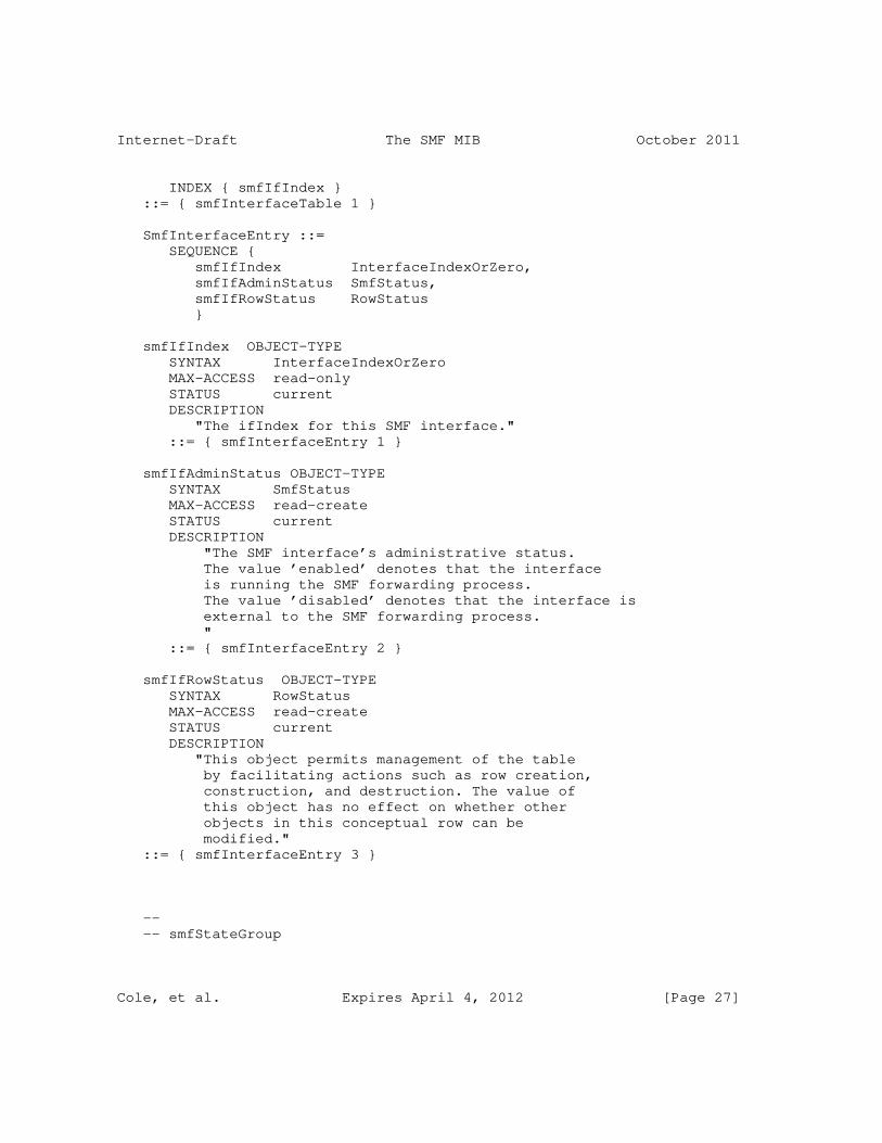
Internet-Draft The SMF MIB October 2011
INDEX { smfIfIndex } ::= { smfInterfaceTable 1 }
SmfInterfaceEntry ::= SEQUENCE { smfIfIndex InterfaceIndexOrZero, smfIfAdminStatus SmfStatus, smfIfRowStatus RowStatus }
smfIfIndex OBJECT-TYPE SYNTAX InterfaceIndexOrZero MAX-ACCESS read-only STATUS current DESCRIPTION "The ifIndex for this SMF interface." ::= { smfInterfaceEntry 1 }
smfIfAdminStatus OBJECT-TYPE SYNTAX SmfStatus MAX-ACCESS read-create STATUS current DESCRIPTION "The SMF interface’s administrative status. The value ’enabled’ denotes that the interface is running the SMF forwarding process. The value ’disabled’ denotes that the interface is external to the SMF forwarding process. " ::= { smfInterfaceEntry 2 }
smfIfRowStatus OBJECT-TYPE SYNTAX RowStatus MAX-ACCESS read-create STATUS current DESCRIPTION "This object permits management of the table by facilitating actions such as row creation, construction, and destruction. The value of this object has no effect on whether other objects in this conceptual row can be modified." ::= { smfInterfaceEntry 3 }
-- -- smfStateGroup
Cole, et al. Expires April 4, 2012 [Page 27]

Internet-Draft The SMF MIB October 2011
-- -- Contains information describing the current state of the SMF -- process such as the current inclusion in the RS or not. --
smfStateGroup OBJECT IDENTIFIER ::= { smfMIBObjects 3 }
smfNodeRsStatusIncluded OBJECT-TYPE SYNTAX TruthValue MAX-ACCESS read-only STATUS current DESCRIPTION "The current status of the SMF node in the context of the MANETs relay set. A value of true(1) indicates that the node is currently part of the MANET Relay Set. A value of false(2) indicates that the node is currently not part of the MANET Relay Set." ::= { smfStateGroup 1 }
smfDpdMemoryOverflow OBJECT-TYPE SYNTAX Counter32 MAX-ACCESS read-only STATUS current DESCRIPTION "The number of times that the memory for caching records for DPD overran and records had to be flushed. The number of records to be flushed upon a buffer overflow is an implementation specific decision. " ::= { smfStateGroup 2 }
-- -- Dynamically Discovered Multicast Addr Table --
smfDiscoveredAddrForwardingTable OBJECT-TYPE SYNTAX SEQUENCE OF SmfDiscoveredAddrForwardingEntry MAX-ACCESS not-accessible STATUS current DESCRIPTION "This state table, smfDiscoveredAddrForwardingTable contains additional, dynamically discovered address for forwarding.
Each row is associated with a range of multicast addresses, and ranges for different rows
Cole, et al. Expires April 4, 2012 [Page 28]

Internet-Draft The SMF MIB October 2011
must be disjoint. " ::= { smfStateGroup 3 }
smfDiscoveredAddrForwardingEntry OBJECT-TYPE SYNTAX SmfDiscoveredAddrForwardingEntry MAX-ACCESS not-accessible STATUS current DESCRIPTION "An entry (conceptual row) containing the information on a particular multicast scope." INDEX { smfDiscoveredAddrForwardingAddrType, smfDiscoveredAddrForwardingFirstAddr } ::= { smfDiscoveredAddrForwardingTable 1 }
SmfDiscoveredAddrForwardingEntry ::= SEQUENCE { smfDiscoveredAddrForwardingAddrType InetAddressType, smfDiscoveredAddrForwardingFirstAddr InetAddress, smfDiscoveredAddrForwardingLastAddr InetAddress }
smfDiscoveredAddrForwardingAddrType OBJECT-TYPE SYNTAX InetAddressType MAX-ACCESS not-accessible STATUS current DESCRIPTION "The type of the addresses in the multicast forwarding range. Legal values correspond to the subset of address families for which multicast address allocation is supported." ::= { smfDiscoveredAddrForwardingEntry 1 }
smfDiscoveredAddrForwardingFirstAddr OBJECT-TYPE SYNTAX InetAddress (SIZE(0..20)) MAX-ACCESS not-accessible STATUS current DESCRIPTION "The first address in the multicast scope range. The type of this address is determined by the value of the smfConfiguredAddrForwardingAddrType object." ::= { smfDiscoveredAddrForwardingEntry 2 }
smfDiscoveredAddrForwardingLastAddr OBJECT-TYPE SYNTAX InetAddress (SIZE(0..20)) MAX-ACCESS read-create STATUS current DESCRIPTION "The last address in the multicast scope range.
Cole, et al. Expires April 4, 2012 [Page 29]

Internet-Draft The SMF MIB October 2011
The type of this address is determined by the value of the smfConfiguredAddrForwardingAddrType object." ::= { smfDiscoveredAddrForwardingEntry 3 }
-- -- SMF Neighbor Table --
smfNeighborTable OBJECT-TYPE SYNTAX SEQUENCE OF SmfNeighborEntry MAX-ACCESS not-accessible STATUS current DESCRIPTION "The SMF NeighborTable describes the current neighbor nodes, their address and SMF RSSA and the interface on which they can be reached." REFERENCE "Simplified Multicast Forwarding for MANET (SMF), Macker, J., July 2009. Section 7: SMF Neighborhood Discovery Requirements." ::= { smfStateGroup 4 }
smfNeighborEntry OBJECT-TYPE SYNTAX SmfNeighborEntry MAX-ACCESS not-accessible STATUS current DESCRIPTION "The SMF Neighbor Table contains the set of one-hop neighbors, the interface they are reachable on and the SMF RSSA they are currently running." INDEX { smfNeighborIpAddrType, smfNeighborIpAddr, smfNeighborPrefixLen } ::= { smfNeighborTable 1 }
SmfNeighborEntry ::= SEQUENCE { smfNeighborIpAddrType InetAddressType, smfNeighborIpAddr InetAddress, smfNeighborPrefixLen InetAddressPrefixLength, smfNeighborRSSA SmfRssaID, smfNeighborNextHopInterface InterfaceIndexOrZero }
Cole, et al. Expires April 4, 2012 [Page 30]

Internet-Draft The SMF MIB October 2011
smfNeighborIpAddrType OBJECT-TYPE SYNTAX InetAddressType MAX-ACCESS not-accessible STATUS current DESCRIPTION "The neighbor IP address type." ::= { smfNeighborEntry 1 }
smfNeighborIpAddr OBJECT-TYPE SYNTAX InetAddress MAX-ACCESS not-accessible STATUS current DESCRIPTION "The neighbor Inet IPv4 or IPv6 address." ::= { smfNeighborEntry 2 }
smfNeighborPrefixLen OBJECT-TYPE SYNTAX InetAddressPrefixLength MAX-ACCESS not-accessible STATUS current DESCRIPTION "The prefix length. This is a decimal value that indicates the number of contiguous, higher-order bits of the address that make up the network portion of the address." ::= { smfNeighborEntry 3 }
smfNeighborRSSA OBJECT-TYPE SYNTAX SmfRssaID MAX-ACCESS read-only STATUS current DESCRIPTION "The current RSSA running on the neighbor. The list is identical to that described above for the smfRssa object." ::= { smfNeighborEntry 4 }
smfNeighborNextHopInterface OBJECT-TYPE SYNTAX InterfaceIndexOrZero MAX-ACCESS read-only STATUS current DESCRIPTION "The interface ifIndex over which the neighbor is reachable in one-hop." ::= { smfNeighborEntry 5 }
Cole, et al. Expires April 4, 2012 [Page 31]

Internet-Draft The SMF MIB October 2011
-- -- SMF Performance Group -- -- Contains objects which help to characterize the -- performance of the SMF RSSA process, such as statistics -- counters. There are two types of SMF RSSA statistics: -- global counters and per interface counters. --
smfPerformanceGroup OBJECT IDENTIFIER ::= { smfMIBObjects 4 }
smfGlobalPerfGroup OBJECT IDENTIFIER ::= { smfPerformanceGroup 1 }
-- -- IPv4 packet counters --
smfIpv4MultiPktsRecvTotal OBJECT-TYPE SYNTAX Counter32 MAX-ACCESS read-only STATUS current DESCRIPTION "A counter of the total number of multicast IPv4 packets received by the device." ::= { smfGlobalPerfGroup 1 }
smfIpv4MultiPktsForwardedTotal OBJECT-TYPE SYNTAX Counter32 MAX-ACCESS read-only STATUS current DESCRIPTION "A counter of the total number of multicast IPv4 packets forwarded by the device." ::= { smfGlobalPerfGroup 2 }
smfIpv4DuplMultiPktsDetectedTotal OBJECT-TYPE SYNTAX Counter32 MAX-ACCESS read-only STATUS current DESCRIPTION "A counter of the total number of duplicate multicast IPv4 packets detected by the device." ::= { smfGlobalPerfGroup 3 }
smfIpv4DroppedMultiPktsTTLExceededTotal OBJECT-TYPE
Cole, et al. Expires April 4, 2012 [Page 32]
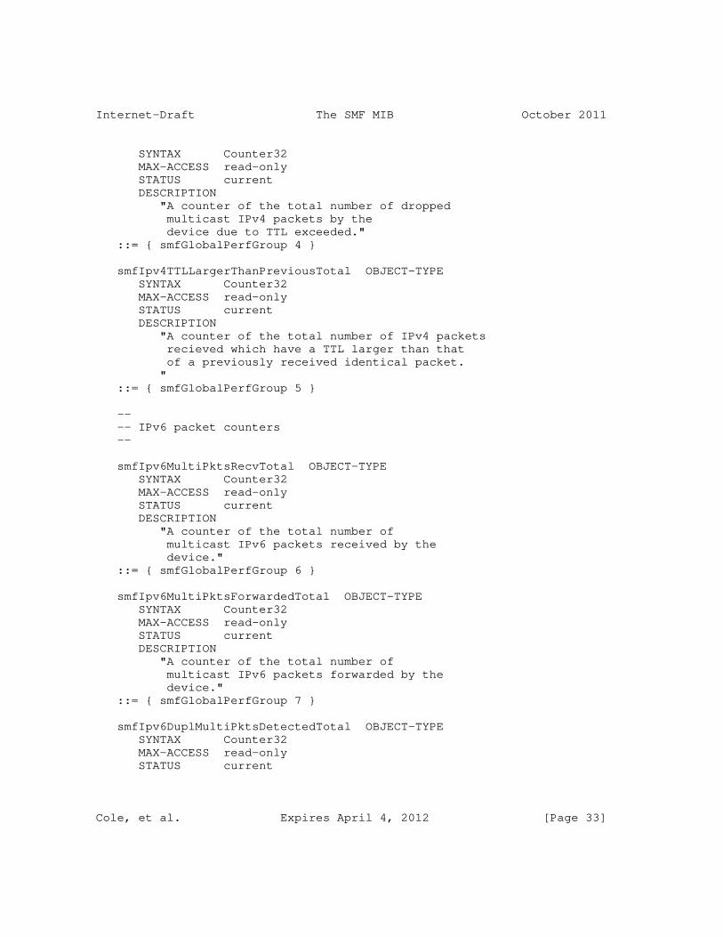
Internet-Draft The SMF MIB October 2011
SYNTAX Counter32 MAX-ACCESS read-only STATUS current DESCRIPTION "A counter of the total number of dropped multicast IPv4 packets by the device due to TTL exceeded." ::= { smfGlobalPerfGroup 4 }
smfIpv4TTLLargerThanPreviousTotal OBJECT-TYPE SYNTAX Counter32 MAX-ACCESS read-only STATUS current DESCRIPTION "A counter of the total number of IPv4 packets recieved which have a TTL larger than that of a previously received identical packet. " ::= { smfGlobalPerfGroup 5 }
-- -- IPv6 packet counters --
smfIpv6MultiPktsRecvTotal OBJECT-TYPE SYNTAX Counter32 MAX-ACCESS read-only STATUS current DESCRIPTION "A counter of the total number of multicast IPv6 packets received by the device." ::= { smfGlobalPerfGroup 6 }
smfIpv6MultiPktsForwardedTotal OBJECT-TYPE SYNTAX Counter32 MAX-ACCESS read-only STATUS current DESCRIPTION "A counter of the total number of multicast IPv6 packets forwarded by the device." ::= { smfGlobalPerfGroup 7 }
smfIpv6DuplMultiPktsDetectedTotal OBJECT-TYPE SYNTAX Counter32 MAX-ACCESS read-only STATUS current
Cole, et al. Expires April 4, 2012 [Page 33]

Internet-Draft The SMF MIB October 2011
DESCRIPTION "A counter of the total number of duplicate multicast IPv6 packets detected by the device." ::= { smfGlobalPerfGroup 8 }
smfIpv6DroppedMultiPktsTTLExceededTotal OBJECT-TYPE SYNTAX Counter32 MAX-ACCESS read-only STATUS current DESCRIPTION "A counter of the total number of dropped multicast IPv6 packets by the device due to TTL exceeded." ::= { smfGlobalPerfGroup 9 }
smfIpv6TTLLargerThanPreviousTotal OBJECT-TYPE SYNTAX Counter32 MAX-ACCESS read-only STATUS current DESCRIPTION "A counter of the total number of IPv6 packets recieved which have a TTL larger than that of a previously recived identical packet. " ::= { smfGlobalPerfGroup 10 }
smfIpv6HAVAssistsReqdTotal OBJECT-TYPE SYNTAX Counter32 MAX-ACCESS read-only STATUS current DESCRIPTION "A counter of the total number of IPv6 packets recieved which required the HAV assist for DPD. " ::= { smfGlobalPerfGroup 11 }
smfIpv6DpdHeaderInsertionsTotal OBJECT-TYPE SYNTAX Counter32 MAX-ACCESS read-only STATUS current DESCRIPTION "A counter of the total number of IPv6 packets recieved which the device inserted the DPD header option. " ::= { smfGlobalPerfGroup 12 }
Cole, et al. Expires April 4, 2012 [Page 34]

Internet-Draft The SMF MIB October 2011
-- -- Per SMF Interface Performance Table --
smfInterfacePerfGroup OBJECT IDENTIFIER ::= { smfPerformanceGroup 2 }
smfIpv4InterfacePerfTable OBJECT-TYPE SYNTAX SEQUENCE OF SmfIpv4InterfacePerfEntry MAX-ACCESS not-accessible STATUS current DESCRIPTION "The SMF Interface Performance Table describes the SMF statistics per interface." ::= { smfInterfacePerfGroup 1 }
smfIpv4InterfacePerfEntry OBJECT-TYPE SYNTAX SmfIpv4InterfacePerfEntry MAX-ACCESS not-accessible STATUS current DESCRIPTION "The SMF Interface Performance entry describes the statistics for a particular node interface." INDEX { smfIpv4IfPerfIfIndex } ::= { smfIpv4InterfacePerfTable 1 }
SmfIpv4InterfacePerfEntry ::= SEQUENCE { smfIpv4IfPerfIfIndex InterfaceIndexOrZero, smfIpv4MultiPktsRecvPerIf Counter32, smfIpv4MultiPktsForwardedPerIf Counter32, smfIpv4DuplMultiPktsDetectedPerIf Counter32, smfIpv4DroppedMultiPktsTTLExceededPerIf Counter32, smfIpv4TTLLargerThanPreviousPerIf Counter32 }
smfIpv4IfPerfIfIndex OBJECT-TYPE SYNTAX InterfaceIndexOrZero MAX-ACCESS not-accessible STATUS current DESCRIPTION "The ifIndex for this node interface that is collecting this set of performance management statistics." ::= { smfIpv4InterfacePerfEntry 1 }
smfIpv4MultiPktsRecvPerIf OBJECT-TYPE
Cole, et al. Expires April 4, 2012 [Page 35]

Internet-Draft The SMF MIB October 2011
SYNTAX Counter32 MAX-ACCESS read-only STATUS current DESCRIPTION "A counter of the number of multicast IP packets received by the device on this interface." ::= { smfIpv4InterfacePerfEntry 2 }
smfIpv4MultiPktsForwardedPerIf OBJECT-TYPE SYNTAX Counter32 MAX-ACCESS read-only STATUS current DESCRIPTION "A counter of the number of multicast IP packets forwarded by the device on this interface." ::= { smfIpv4InterfacePerfEntry 3 }
smfIpv4DuplMultiPktsDetectedPerIf OBJECT-TYPE SYNTAX Counter32 MAX-ACCESS read-only STATUS current DESCRIPTION "A counter of the number of duplicate multicast IP packets detected by the device on this interface." ::= { smfIpv4InterfacePerfEntry 4 }
smfIpv4DroppedMultiPktsTTLExceededPerIf OBJECT-TYPE SYNTAX Counter32 MAX-ACCESS read-only STATUS current DESCRIPTION "A counter of the total number of dropped multicast IPv4 packets by the device due to TTL exceeded." ::= { smfIpv4InterfacePerfEntry 5 }
smfIpv4TTLLargerThanPreviousPerIf OBJECT-TYPE SYNTAX Counter32 MAX-ACCESS read-only STATUS current DESCRIPTION "A counter of the total number of IPv4 packets recieved which have a TTL larger than that of a previously recived identical packet. "
Cole, et al. Expires April 4, 2012 [Page 36]

Internet-Draft The SMF MIB October 2011
::= { smfIpv4InterfacePerfEntry 6 }
smfIpv6InterfacePerfTable OBJECT-TYPE SYNTAX SEQUENCE OF SmfIpv6InterfacePerfEntry MAX-ACCESS not-accessible STATUS current DESCRIPTION "The SMF Interface Performance Table describes the SMF statistics per interface." ::= { smfInterfacePerfGroup 2 }
smfIpv6InterfacePerfEntry OBJECT-TYPE SYNTAX SmfIpv6InterfacePerfEntry MAX-ACCESS not-accessible STATUS current DESCRIPTION "The SMF Interface Performance entry describes the statistics for a particular node interface." INDEX { smfIpv6IfPerfIfIndex } ::= { smfIpv6InterfacePerfTable 1 }
SmfIpv6InterfacePerfEntry ::= SEQUENCE { smfIpv6IfPerfIfIndex InterfaceIndexOrZero, smfIpv6MultiPktsRecvPerIf Counter32, smfIpv6MultiPktsForwardedPerIf Counter32, smfIpv6DuplMultiPktsDetectedPerIf Counter32, smfIpv6DroppedMultiPktsTTLExceededPerIf Counter32, smfIpv6TTLLargerThanPreviousPerIf Counter32, smfIpv6HAVAssistsReqdPerIf Counter32, smfIpv6DpdHeaderInsertionsPerIf Counter32 }
smfIpv6IfPerfIfIndex OBJECT-TYPE SYNTAX InterfaceIndexOrZero MAX-ACCESS not-accessible STATUS current DESCRIPTION "The ifIndex for this node interface that is collecting this set of performance management statistics.
For packets generated locally at this node, performance counters are assigned to the loopback
Cole, et al. Expires April 4, 2012 [Page 37]

Internet-Draft The SMF MIB October 2011
interface. " ::= { smfIpv6InterfacePerfEntry 1 }
smfIpv6MultiPktsRecvPerIf OBJECT-TYPE SYNTAX Counter32 MAX-ACCESS read-only STATUS current DESCRIPTION "A counter of the number of multicast IP packets received by the device on this interface." ::= { smfIpv6InterfacePerfEntry 2 }
smfIpv6MultiPktsForwardedPerIf OBJECT-TYPE SYNTAX Counter32 MAX-ACCESS read-only STATUS current DESCRIPTION "A counter of the number of multicast IP packets forwarded by the device on this interface." ::= { smfIpv6InterfacePerfEntry 3 }
smfIpv6DuplMultiPktsDetectedPerIf OBJECT-TYPE SYNTAX Counter32 MAX-ACCESS read-only STATUS current DESCRIPTION "A counter of the number of duplicate multicast IP packets detected by the device on this interface." ::= { smfIpv6InterfacePerfEntry 4 }
smfIpv6DroppedMultiPktsTTLExceededPerIf OBJECT-TYPE SYNTAX Counter32 MAX-ACCESS read-only STATUS current DESCRIPTION "A counter of the number of dropped multicast IP packets by the device on this interface due to TTL exceeded." ::= { smfIpv6InterfacePerfEntry 5 }
smfIpv6TTLLargerThanPreviousPerIf OBJECT-TYPE SYNTAX Counter32 MAX-ACCESS read-only
Cole, et al. Expires April 4, 2012 [Page 38]

Internet-Draft The SMF MIB October 2011
STATUS current DESCRIPTION "A counter of the total number of IPv6 packets recieved which have a TTL larger than that of a previously recived identical packet. " ::= { smfIpv6InterfacePerfEntry 6 }
smfIpv6HAVAssistsReqdPerIf OBJECT-TYPE SYNTAX Counter32 MAX-ACCESS read-only STATUS current DESCRIPTION "A counter of the total number of IPv6 packets recieved which required the HAV assist for DPD. " ::= { smfIpv6InterfacePerfEntry 7 }
smfIpv6DpdHeaderInsertionsPerIf OBJECT-TYPE SYNTAX Counter32 MAX-ACCESS read-only STATUS current DESCRIPTION "A counter of the total number of IPv6 packets recieved which the device inserted the DPD header option. " ::= { smfIpv6InterfacePerfEntry 8 }
-- -- Notifications --
smfMIBNotifControl OBJECT IDENTIFIER ::= { smfMIBNotifications 1 }smfMIBNotifObjects OBJECT IDENTIFIER ::= { smfMIBNotifications 2 }smfMIBNotifStates OBJECT IDENTIFIER ::= { smfMIBNotifications 3 }
-- smfMIBNotifControl smfSetNotification OBJECT-TYPE SYNTAX OCTET STRING (SIZE(4)) MAX-ACCESS read-write STATUS current DESCRIPTION "A 4-octet string serving as a bit map for the notification events defined by the SMF MIB
Cole, et al. Expires April 4, 2012 [Page 39]

Internet-Draft The SMF MIB October 2011
notifications. This object is used to enable and disable specific SMF MIB notifications where a 1 in the bit field represents enabled. The right-most bit (least significant) represents notification 0.
This object is persistent and when written the entity SHOULD save the change to non-volatile storage. " ::= { smfMIBNotifControl 1 }
smfDpdMemoryOverflowThreshold OBJECT-TYPE SYNTAX Integer32 (0..255) MAX-ACCESS read-write STATUS current DESCRIPTION "A threshold value for the ‘smfDpdmemoryOverflowEvents’ object. If the number of occurences exceeds this threshold within the previous number of seconds ’smfDpdMemoryOverflowWindow’, then the ‘smfDpdMemoryOverflowEvent’ notification is sent. " ::= { smfMIBNotifControl 2 }
smfDpdMemoryOverflowWindow OBJECT-TYPE SYNTAX TimeTicks MAX-ACCESS read-write STATUS current DESCRIPTION "A time window value for the ‘smfDpdmemoryOverflowEvents’ object. If the number of occurences exceeds the ‘smfDpdMemoryOverflowThreshold’ within the previous number of seconds ’smfDpdMemoryOverflowWindow’, then the ‘smfDpdMemoryOverflowEvent’ notification is sent. " ::= { smfMIBNotifControl 3 }
smfIpv4DuplMultiPktsDetectedTotalThreshold OBJECT-TYPE SYNTAX Integer32 (0..255) MAX-ACCESS read-write STATUS current
Cole, et al. Expires April 4, 2012 [Page 40]
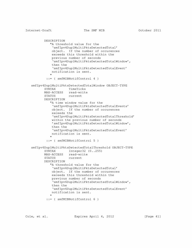
Internet-Draft The SMF MIB October 2011
DESCRIPTION "A threshold value for the ‘smfIpv4DuplMultiPktsDetectedTotal’ object. If the number of occurences exceeds this threshold within the previous number of seconds ‘smfIpv4DuplMultiPktsDetectedTotalWindow’, then the ‘smfIpv4DuplMultiPktsDetectedTotalEvent’ notification is sent. " ::= { smfMIBNotifControl 4 }
smfIpv4DuplMultiPktsDetectedTotalWindow OBJECT-TYPE SYNTAX TimeTicks MAX-ACCESS read-write STATUS current DESCRIPTION "A time window value for the ‘smfIpv4DuplMultiPktsDetectedTotalEvents’ object. If the number of occurences exceeds the ‘smfIpv4DuplMultiPktsDetectedTotalThreshold’ within the previous number of seconds ’smfIpv4DuplMultiPktsDetectedTotalWindow’, then the ‘smfIpv4DuplMultiPktsDetectedTotalEvent’ notification is sent. " ::= { smfMIBNotifControl 5 }
smfIpv6DuplMultiPktsDetectedTotalThreshold OBJECT-TYPE SYNTAX Integer32 (0..255) MAX-ACCESS read-write STATUS current DESCRIPTION "A threshold value for the ‘smfIpv6DuplMultiPktsDetectedTotal’ object. If the number of occurences exceeds this threshold within the previous number of seconds ‘smfIpv6DuplMultiPktsDetectedTotalWindow’, then the ‘smfIpv6DuplMultiPktsDetectedTotalEvent’ notification is sent. " ::= { smfMIBNotifControl 6 }
Cole, et al. Expires April 4, 2012 [Page 41]

Internet-Draft The SMF MIB October 2011
smfIpv6DuplMultiPktsDetectedTotalWindow OBJECT-TYPE SYNTAX TimeTicks MAX-ACCESS read-write STATUS current DESCRIPTION "A time window value for the ‘smfIpv6DuplMultiPktsDetectedTotalEvents’ object. If the number of occurences exceeds the ‘smfIpv6DuplMultiPktsDetectedTotalThreshold’ within the previous number of seconds ’smfIpv6DuplMultiPktsDetectedTotalWindow’, then the ‘smfIpv6DuplMultiPktsDetectedTotalEvent’ notification is sent. " ::= { smfMIBNotifControl 7 }
-- smfMIBNotifObjects
smfAdminStatusChange NOTIFICATION-TYPE OBJECTS { smfRouterIDAddrType, -- The originator of -- the notification. smfRouterID, -- The originator of -- the notification. smfAdminStatus -- The new status of the -- SMF process. } STATUS current DESCRIPTION "smfAdminStatusChange is a notification sent when a the ’smfAdminStatus’ object changes. " ::= { smfMIBNotifObjects 1 }
smfConfiguredOpModeChange NOTIFICATION-TYPE OBJECTS { smfRouterIDAddrType, -- The originator of -- the notification. smfRouterID, -- The originator of -- the notification. smfConfiguredOpMode -- The new Operations -- Mode of the SMF -- process. } STATUS current DESCRIPTION
Cole, et al. Expires April 4, 2012 [Page 42]

Internet-Draft The SMF MIB October 2011
"smfConfiguredOpModeChange is a notification sent when a the ’smfConfiguredOpMode’ object changes. " ::= { smfMIBNotifObjects 2 }
smfConfiguredRssaChange NOTIFICATION-TYPE OBJECTS { smfRouterIDAddrType, -- The originator of -- the notification. smfRouterID, -- The originator of -- the notification. smfConfiguredRssa -- The new RSSA for -- the SMF process. } STATUS current DESCRIPTION "smfAdminStatusChange is a notification sent when a the ’smfConfiguredRssa’ object changes. " ::= { smfMIBNotifObjects 3 }
smfIfAdminStatusChange NOTIFICATION-TYPE OBJECTS { smfRouterIDAddrType, -- The originator of -- the notification. smfRouterID, -- The originator of -- the notification. smfIfIndex, -- The interface whose -- status has changed. smfIfAdminStatus -- The new status of the -- SMF interface. } STATUS current DESCRIPTION "smfIfAdminStatusChange is a notification sent when a the ’smfIfAdminStatus’ object changes. " ::= { smfMIBNotifObjects 4 }
smfDpdMemoryOverflowEvent NOTIFICATION-TYPE OBJECTS { smfRouterIDAddrType, -- The originator of -- the notification. smfRouterID, -- The originator of -- the notification. smfDpdMemoryOverflow -- The counter of -- the overflows. } STATUS current DESCRIPTION
Cole, et al. Expires April 4, 2012 [Page 43]

Internet-Draft The SMF MIB October 2011
"smfDpdMemoryOverflowEvents is sent when the number of memory overflow events exceeds the the ’smfDpdMemoryOverflowThreshold’ within the previous number of seconds defined by the ’smfDpdMemoryOverflowWindow’. " ::= { smfMIBNotifObjects 5 }
smfIpv4DuplMultiPktsDetectedTotalEvents NOTIFICATION-TYPE OBJECTS { smfRouterIDAddrType, -- The originator of -- the notification. smfRouterID, -- The originator of -- the notification. smfIpv4DuplMultiPktsDetectedTotal -- The -- counter of detected -- duplicates. } STATUS current DESCRIPTION "smfIpv4DuplMultiPktsDetectedTotal is a notification sent when the number of IPv4 duplicate packets detected exceeds the ’smfIpv4DuplMultiPktsDetectedTotalThreshold’ during the previous number of seconds ’smfIpv4DuplPktsDetectedTotalWindow’. " ::= { smfMIBNotifObjects 6 }
smfIpv6DuplMultiPktsDetectedTotalEvents NOTIFICATION-TYPE OBJECTS { smfRouterIDAddrType, -- The originator of -- the notification. smfRouterID, -- The originator of -- the notification. smfIpv6DuplMultiPktsDetectedTotal -- The -- counter of detected -- duplicates. } STATUS current DESCRIPTION "smfIpv6DuplMultiPktsDetectedTotal is a notification sent when the number of IPv6 duplicate packets detected exceeds the ’smfIpv6DuplMultiPktsDetectedTotalThreshold’ during the previous number of seconds ’smfIpv6DuplPktsDetectedTotalWindow’. " ::= { smfMIBNotifObjects 7 }
Cole, et al. Expires April 4, 2012 [Page 44]

Internet-Draft The SMF MIB October 2011
-- smfMIBNotifStates -- is empty.
-- -- Compliance Statements --
smfCompliances OBJECT IDENTIFIER ::= { smfMIBConformance 1 } smfMIBGroups OBJECT IDENTIFIER ::= { smfMIBConformance 2 }
smfBasicCompliance MODULE-COMPLIANCE STATUS current DESCRIPTION "The basic implementation requirements for managed network entities that implement the SMF RSSA process." MODULE -- this module MANDATORY-GROUPS { smfCapabObjectsGroup, smfConfigObjectsGroup } ::= { smfCompliances 1 }
smfFullCompliance MODULE-COMPLIANCE STATUS current DESCRIPTION "The full implementation requirements for managed network entities that implement the SMF RSSA process." MODULE -- this module MANDATORY-GROUPS { smfCapabObjectsGroup, smfConfigObjectsGroup, smfStateObjectsGroup, smfPerfObjectsGroup, smfNotifObjectsGroup, smfNotificationsGroup } ::= { smfCompliances 2 }
-- -- Units of Conformance --
smfCapabObjectsGroup OBJECT-GROUP OBJECTS { smfOpModeCapabilitiesName, smfOpModeCapabilitiesReference,
smfRssaCapabilitiesName,
Cole, et al. Expires April 4, 2012 [Page 45]

Internet-Draft The SMF MIB October 2011
smfRssaCapabilitiesReference } STATUS current DESCRIPTION "Set of SMF configuration objects implemented in this module." ::= { smfMIBGroups 1 }
smfConfigObjectsGroup OBJECT-GROUP OBJECTS { smfAdminStatus, smfRouterIDAddrType, smfRouterID, smfIfIndex, smfConfiguredOpMode, smfConfiguredRssa, smfRssaMember, smfIpv4Dpd, smfIpv6Dpd, smfMaxPktLifetime, smfDpdMaxMemorySize, smfDpdEntryMaxLifetime, smfNhdpRssaMesgTLVIncluded, smfNhdpRssaAddrBlockTLVIncluded,
smfConfiguredAddrForwardingLastAddr, smfConfiguredAddrForwardingStatus,
smfIfAdminStatus, smfIfRowStatus } STATUS current DESCRIPTION "Set of SMF configuration objects implemented in this module." ::= { smfMIBGroups 2 }
smfStateObjectsGroup OBJECT-GROUP OBJECTS { smfNodeRsStatusIncluded, smfDpdMemoryOverflow,
smfDiscoveredAddrForwardingLastAddr,
smfNeighborRSSA, smfNeighborNextHopInterface } STATUS current
Cole, et al. Expires April 4, 2012 [Page 46]
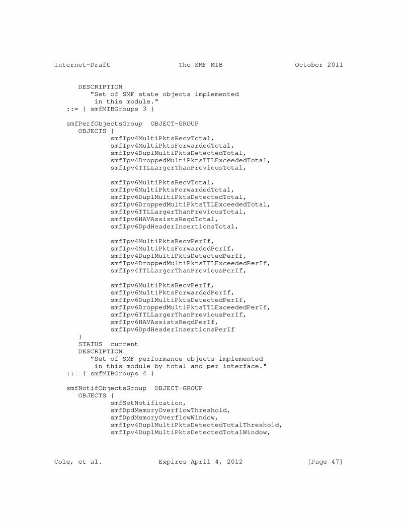
Internet-Draft The SMF MIB October 2011
DESCRIPTION "Set of SMF state objects implemented in this module." ::= { smfMIBGroups 3 }
smfPerfObjectsGroup OBJECT-GROUP OBJECTS { smfIpv4MultiPktsRecvTotal, smfIpv4MultiPktsForwardedTotal, smfIpv4DuplMultiPktsDetectedTotal, smfIpv4DroppedMultiPktsTTLExceededTotal, smfIpv4TTLLargerThanPreviousTotal,
smfIpv6MultiPktsRecvTotal, smfIpv6MultiPktsForwardedTotal, smfIpv6DuplMultiPktsDetectedTotal, smfIpv6DroppedMultiPktsTTLExceededTotal, smfIpv6TTLLargerThanPreviousTotal, smfIpv6HAVAssistsReqdTotal, smfIpv6DpdHeaderInsertionsTotal,
smfIpv4MultiPktsRecvPerIf, smfIpv4MultiPktsForwardedPerIf, smfIpv4DuplMultiPktsDetectedPerIf, smfIpv4DroppedMultiPktsTTLExceededPerIf, smfIpv4TTLLargerThanPreviousPerIf,
smfIpv6MultiPktsRecvPerIf, smfIpv6MultiPktsForwardedPerIf, smfIpv6DuplMultiPktsDetectedPerIf, smfIpv6DroppedMultiPktsTTLExceededPerIf, smfIpv6TTLLargerThanPreviousPerIf, smfIpv6HAVAssistsReqdPerIf, smfIpv6DpdHeaderInsertionsPerIf } STATUS current DESCRIPTION "Set of SMF performance objects implemented in this module by total and per interface." ::= { smfMIBGroups 4 }
smfNotifObjectsGroup OBJECT-GROUP OBJECTS { smfSetNotification, smfDpdMemoryOverflowThreshold, smfDpdMemoryOverflowWindow, smfIpv4DuplMultiPktsDetectedTotalThreshold, smfIpv4DuplMultiPktsDetectedTotalWindow,
Cole, et al. Expires April 4, 2012 [Page 47]

Internet-Draft The SMF MIB October 2011
smfIpv6DuplMultiPktsDetectedTotalThreshold, smfIpv6DuplMultiPktsDetectedTotalWindow } STATUS current DESCRIPTION "Set of SMF notification control objects implemented in this module." ::= { smfMIBGroups 5 }
smfNotificationsGroup NOTIFICATION-GROUP NOTIFICATIONS { smfAdminStatusChange, smfConfiguredOpModeChange, smfConfiguredRssaChange, smfIfAdminStatusChange, smfDpdMemoryOverflowEvent, smfIpv4DuplMultiPktsDetectedTotalEvents, smfIpv6DuplMultiPktsDetectedTotalEvents } STATUS current DESCRIPTION "Set of SMF notifications implemented in this module." ::= { smfMIBGroups 6 }
END
8. Security Considerations
This section discusses security implications of the choices made in this SMF-MIB module.
There are a number of management objects defined in this MIB module with a MAX-ACCESS clause of read-write and/or read-create. Such objects may be considered sensitive or vulnerable in some network environments. The support for SET operations in a non-secure environment without proper protection can have a negative effect on network operations. These are the tables and objects and their sensitivity/vulnerability:
o ’smfAdminStatus’ - this writable configuration object controls the operational status of the SMF process. If this setting is configured inconsistently across the MANET multicasting domain, then delivery of multicast data may be inconsistent across the domain; some nodes may not receive multicast data intended for
Cole, et al. Expires April 4, 2012 [Page 48]

Internet-Draft The SMF MIB October 2011
them.
o ’smfRouterIDAddrType’ and ’smfRouterID’ - these writable configuration objects define the ID of the SMF process. These objects should be configured with a routable address defined on the local SMF device. The smfRouterID is a logical identification that MUST be consistent across interoperating SMF neighborhoods and it is RECOMMENDED to be chosen as the numerically largest address contained in a node’s ’Neighbor Address List’ as defined in NHDP. A smfRouterID MUST be unique within the scope of the operating MANET network regardless of the method used for selecting it.
o ’smfConfiguredOpMode’ - this writable configuration objects define the operational mode of the SMF process. The operational mode defines how the SMF process develops its local estimate of the CDS.
o ’smfConfiguredRssa’ - this writable configuration object sets the specific Reduced Set Selection Algorithm (RSSA) for the SMF process. If this object is set inconsistently across the MANET domain, multicast delivery of data will fail.
o ’smfRssaMember’ - this writable configuration object sets the ’interest’ of the local SMF node in participating in the CDS. Setting this object to ’never(3)’ on a highly highly connected device could lead to frequent island formation. Setting this object to ’always(2)’ could support data ex-filtration from the MANET domain.
o ’smfIpv4Dpd’ - this writable configuration object sets the duplicate packet detection method for forwarding of IPv4 multicast packets.
o ’smfIpv6Dpd’ - this writable configuration object sets the duplicate packet detection method for forwarding of IPv6 multicast packets.
o ’smfMaxPktLifetime’ - this writable configuration object sets the estimate of the network packet traversal time. If set too small, this could lead to poor multicast data delivery ratios throughout the MANET domain.
o ’smfDpdMaxMemorySize’ - this writable configuration object sets the memory storage size (in Kilo-Bytes) for the cached DPD records for the combined IPv4 and IPv6 methods. If set too small this could lead to poor performance of the duplicate packet protection algorithms and lead to inefficient resource, e.g., link,
Cole, et al. Expires April 4, 2012 [Page 49]

Internet-Draft The SMF MIB October 2011
utilization within the MANET domain. The local SMF device should protect itself against memory overruns in the event that too large a setting is requested.
o ’smfDpdEntryMaxLifetime’ - this writable configuration object sets the maximum lifetime (in seconds) for the cached DPD records for the combined IPv4 and IPv6 methods. If the memory is running low prior to the MaxLifetimes being exceeded, the local SMF devices should purge the oldest records first.
o ’smfNhdpRssaMesgTLVIncluded’ - this writable configuration object indicates whether the associated NHDP messages include the the RSSA Message TLV, or not. It is highly RECOMMENDED that this object be set to ’true(1)’.
o ’smfNhdpRssaAddrBlockTLVIncluded’ - this writable configuration object indicates whether the associated NHDP messages include the the RSSA Address Block TLV, or not. The smfNhdpRssaAddrBlockTLVIncluded is optional in all cases as it depends on the existence of an address block which may not be present. If this SMF device is configured with NHDP, then this object should be set to ’true(1)’.
o ’smfConfiguredAddrForwardingTable’ - the writable configuration objects in this table indicate which multicast IP address are to be forwarded by this SMF node. Misconfiguration of rows within this table can limit the ability of this SMF device to forward multicast data.
o ’smfInterfaceTable’ - the writable configuration objects in this table indicate which SMF node interfaces are participating in the SMF packet forwarding process. Misconfiguration of rows within this table can limit the ability of this SMF device to forward multicast data.
Some of the readable objects in this MIB module (i.e., objects with a MAX-ACCESS other than not-accessible) may be considered sensitive or vulnerable in some network environments. It is thus important to control even GET and/or NOTIFY access to these objects and possibly to even encrypt the values of these objects when sending them over the network via SNMP. These are the tables and objects and their sensitivity/vulnerability:
o ’smfNodeRsStatusIncluded’ - this readable state object indicates that this SMF node is part of the CDS, or not. Being part of the CDS makes this node a distinguished device. It could be exploited for data ex-filtration, or denial of service attacks.
Cole, et al. Expires April 4, 2012 [Page 50]

Internet-Draft The SMF MIB October 2011
o ’smfDiscoveredAddrForwardingTable’ - the readable state objects in this table indicate which, dynamically discovered, multicast IP address are to be forwarded by this SMF node.
o ’smfNeighborTable’ - the readable state objects in this table indicate current neighbor nodes to this SMF node. Exposing this information to an attacker could allow the attacker easier access to the larger MANET domain.
The remainder of the objects in the SMF-MIB are performance counter objects. While these give an indication of the activity of the SMF process on this node, it is not expected that exposing these values pose a security risk to the MANET network.
SNMP versions prior to SNMPv3 did not include adequate security. Even if the network itself is secure (for example by using IPSec), even then, there is no control as to who on the secure network is allowed to access and GET/SET (read/change/create/delete) the objects in this MIB module.
It is RECOMMENDED that implementers consider the security features as provided by the SNMPv3 framework (see [RFC3410], section 8), including full support for the SNMPv3 cryptographic mechanisms (for authentication and privacy).
Further, deployment of SNMP versions prior to SNMPv3 is NOT RECOMMENDED. Instead, it is RECOMMENDED to deploy SNMPv3 and to enable cryptographic security. It is then a customer/operator responsibility to ensure that the SNMP entity giving access to an instance of this MIB module is properly configured to give access to the objects only to those principals (users) that have legitimate rights to indeed GET or SET (change/create/delete) them.
9. IANA Considerations
Editor’s Note (to be removed prior to publication): the IANA is requested to assign a value for "XXXX" under the ’experimental’ subtree and to record the assignment in the SMI Numbers registry. When the assignment has been made, the RFC Editor is asked to replace "XXXX" (here and in the MIB module) with the assigned value and to remove this note. Note well: prior to official assignment by the IANA, a draft document MUST use placeholders (such as "XXXX" above) rather than actual numbers. See RFC4181 Section 4.5 for an example of how this is done in a draft MIB module.
Cole, et al. Expires April 4, 2012 [Page 51]

Internet-Draft The SMF MIB October 2011
10. Contributors
This MIB document uses the template authored by D. Harrington which is based on contributions from the MIB Doctors, especially Juergen Schoenwaelder, Dave Perkins, C.M.Heard and Randy Presuhn.
11. References
11.1. Normative References
[RFC2863] McCloghrie, K. and F. Kastenholz, "The Interfaces Group MIB", RFC 2863, June 2000.
[RFC3411] Harrington, D., Presuhn, R., and B. Wijnen, "An Architecture for Describing Simple Network Management Protocol (SNMP) Management Frameworks", STD 62, RFC 3411, December 2002.
[RFC3418] Presuhn, R., "Management Information Base (MIB) for the Simple Network Management Protocol (SNMP)", STD 62, RFC 3418, December 2002.
[RFC4001] Daniele, M., Haberman, B., Routhier, S., and J. Schoenwaelder, "Textual Conventions for Internet Network Addresses", RFC 4001, February 2005.
[RFC2119] Bradner, S., "Key words for use in RFCs to Indicate Requirement Levels", BCP 14, RFC 2119, March 1997.
[RFC2578] McCloghrie, K., Ed., Perkins, D., Ed., and J. Schoenwaelder, Ed., "Structure of Management Information Version 2 (SMIv2)", STD 58, RFC 2578, April 1999.
[RFC2579] McCloghrie, K., Ed., Perkins, D., Ed., and J. Schoenwaelder, Ed., "Textual Conventions for SMIv2", STD 58, RFC 2579, April 1999.
[RFC2580] McCloghrie, K., Perkins, D., and J. Schoenwaelder, "Conformance Statements for SMIv2", STD 58, RFC 2580, April 1999.
[I-D.ietf-manet-smf] Macker, J., "Simplified Multicast Forwarding", draft-ietf-manet-smf-12 (work in progress), July 2011.
Cole, et al. Expires April 4, 2012 [Page 52]

Internet-Draft The SMF MIB October 2011
11.2. Informative References
[RFC3410] Case, J., Mundy, R., Partain, D., and B. Stewart, "Introduction and Applicability Statements for Internet-Standard Management Framework", RFC 3410, December 2002.
Appendix A. Change Log
This section tracks the revision history in the development of this SMF-MIB. It will be removed from the final version of this document.
These changes were made from draft-ietf-manet-smf-mib-02 to draft-ietf-manet-smf-mib-03.
1. Clarified and added discussion of default values for several of the configuration objects within the MIB.
2. Added the security section.
These changes were made from draft-ietf-manet-smf-mib-01 to draft-ietf-manet-smf-mib-02.
1. Added the NotificationGroup to the MIB and updated the ConformanceGroup.
2. Added the definition of an smfRouterID to the MIB. This is later used in the Notifications to indicate the origin of the event to the management station.
3. Removed the Router Priority object as this was used only in the eCDS algorithm and hence should be contained within the future eCDS-MIB.
4. Cleaned up the TEXTUAL CONVENTION for the ‘SmfOpMode’.
5. Filled in some of the missing text in various object descriptions.
These changes were made from draft-ietf-manet-smf-mib-00 to draft-ietf-manet-dsmf-mib-01.
1. Editorial changes to the textual material. These included the addition of the paragraphs on TEXTUAL-CONVENTIONS defined and imported into this MIB and relationships to other MIBs.
2. Identified those objects in the SMF-MIB requiring non-volatile storage.
Cole, et al. Expires April 4, 2012 [Page 53]

Internet-Draft The SMF MIB October 2011
3. Changed the name of the TEXTUAL-CONVENTION ’Status’, defined within this MIB to ’SmfStatus’.
Appendix B. Open Issues
This section contains the set of open issues related to the development and design of the SMF-MIB. This section will not be present in the final version of the MIB and will be removed once all the open issues have been resolved.
1. A careful review by the working group.
Appendix C.
*************************************************************** * Note to the RFC Editor (to be removed prior to publication) * * * * 1) The reference to RFCXXXX within the DESCRIPTION clauses * * of the MIB module point to this draft and are to be * * assigned by the RFC Editor. * * * * 2) The reference to RFCXXX2 throughout this document point * * to the current draft-ietf-manet-smf-xx.txt. This * * need to be replaced with the XXX RFC number. * * * ***************************************************************
Authors’ Addresses
Robert G. Cole US Army CERDEC 6010 Frankford Road Aberdeen Proving Ground, Maryland 21005 USA
Phone: +1 443 395 8744 EMail: [email protected] URI: http://www.cs.jhu.edu/˜rgcole/
Joseph Macker Naval Research Laboratory Washington, D.C. 20375 USA
EMail: [email protected]
Cole, et al. Expires April 4, 2012 [Page 54]
Internet-Draft The SMF MIB October 2011
Brian Adamson Naval Research Laboratory Washington, D.C. 20375 USA
EMail: [email protected]
Sean Harnedy Booz Allen Hamilton 333 City Boulevard West Orange, CA 92868 USA
EMail: [email protected]
Cole, et al. Expires April 4, 2012 [Page 55]
