interoperability unit trans-european … report...trans-european conventional rail system subsystem...
TRANSCRIPT
EUROPEAN RAILWAY AGENCY
File : IU-ENE-081219-FinRep 1.doc PAGE 1 OF 90
INTEROPERABILITY UNIT
TRANS-EUROPEAN CONVENTIONAL RAIL SYSTEM
SUBSYSTEM ENERGY
Reference: IU-ENE-081219-FinRep 1 Document
Type:
Final Report
Version: 1
Date: 19/12/2008
Edited by Reviewed by Approved by
Name Stanislaw LIS
Gianvittorio TAVOLA
Andrzej HARASSEK Jean-Charles PICHANT
Position Project Officer Adviser Head of Interoperability Unit
Name Airy MAGNIEN
Position Head of Economic Evaluation Unit
Date
&
Signat.
__/__/2008 __/__/2008 __/__/2008
European Railway Agency
IU-ENE-081219-FinRep 1 Version 1 Page 2/90
AMENDMENT RECORD
Version Date Section
number
Modification/description Author
1 19/12/2008 All First issue Airy MAGNIEN
Stanislaw LIS
Gianvittorio TAVOLA
European Railway Agency
IU-ENE-081219-FinRep 1 Version 1 Page 3/90
Table of Contents
1. Introduction ............................................................................................................................... 7
1.1 Background to the assignment ............................................................................................... 7
1.2 Summary ......................................................................................................................... 7
2. Abbreviations and references .......................................................................................................... 8
2.1 Abbreviations .................................................................................................................... 8
2.2 Reference Documents ......................................................................................................... 9
3. Working party ........................................................................................................................... 12
3.1 Composition of the WP ...................................................................................................... 12
3.2 Time plan ....................................................................................................................... 12
3.3 Calendar of meetings and level of participation ......................................................................... 14
3.4 Subgroups dealing with specific items .................................................................................... 15
4. Comments on the preliminary report ............................................................................................... 16
5. Development of the Final Draft TSI ................................................................................................. 17
5.1 General changes.............................................................................................................. 17
5.1.1 Introduction of new Interoperability Directive ...................................................................... 17
5.1.2 Introduction of Decision 2008/768/EC .............................................................................. 17
5.1.3 Revision of standards ................................................................................................. 18
5.1.4 1520/1524 rail system ................................................................................................. 18
5.2 Essential requirements for the Energy subsystem ...................................................................... 18
5.2.1 Safety .................................................................................................................... 18
5.2.2 Reliability & availability ................................................................................................ 19
5.2.3 Health .................................................................................................................... 19
5.2.4 Environmental protection ............................................................................................. 20
5.2.5 Technical compatibility ................................................................................................ 21
5.2.6 Maintenance, health & safety ........................................................................................ 21
5.2.7 Table of essential requirements and basic parameters ......................................................... 22
5.2.8 Essential requirements not relevant to the energy sub-system ................................................ 23
5.3 Description of the Energy Subsystem ..................................................................................... 24
5.3.1 Parameters relating to supply system performance (clause 4.2.4 of the TSI) ............................... 24
5.3.2 Continuity of power supply in case of disturbances in tunnels (clause 4.2.5 of the TSI)................... 24
5.3.3 Current capacity, DC systems, trains at standstill (clause 4.2.6 of the TSI) ................................. 24
5.3.4 Regenerative braking (clause 4.2.7 of the TSI) ................................................................... 25
5.3.5 Electrical protection coordination arrangements (clause 4.2.8 of the TSI) ................................... 25
5.3.6 Harmonic and dynamic effects for AC system (clause 4.2.9 of the TSI)...................................... 25
5.3.7 External electromagnetic compatibility (clause 4.2.11 of the TSI) ............................................. 25
5.3.8 Geometry of the overhead contact line - Contact wire height (clause 4.2.13.1 of the TSI) ................ 25
5.3.9 Geometry of the overhead contact line - Lateral deviation (clause 4.2.13.3 of the TSI) ................... 25
5.3.10 Pantograph gauge (clause 4.2.14 of the TSI) ................................................................. 26
5.3.11 Dynamic behavior and quality of current collection (clause 4.2.16 of the TSI) ........................... 26
5.3.12 Pantograph spacing (clause 4.2.17 of the TSI) ................................................................ 27
5.3.13 Contact wire material (clause 4.2.18 of the TSI) .............................................................. 27
5.3.14 Electric consumption measuring equipment (clause 4.2.21 of the TSI) ................................... 27
European Railway Agency
IU-ENE-081219-FinRep 1 Version 1 Page 4/90
5.3.15 Functional and technical specifications of the interfaces (clause 4.3 of the TSI) ........................ 27
5.4 Interoperability Constituents (Chapter 5 of the TSI) .................................................................... 28
5.5 Assessment of Conformity (Chapter 6 of the TSI) ...................................................................... 28
5.5.1 Existing solutions for Interoperability Constituents (clause 6.1.2.2 of the TSI) .............................. 28
5.5.2 Application of modules (clause 6.2.2 of the TSI) ................................................................. 28
5.6 Implementation of the Energy TSI (Chapter 7 of the TSI) ............................................................. 28
5.6.1 Introduction ............................................................................................................. 28
5.6.2 Existing subsystem that are not subject to a renewal or upgrading project (clause 7.4.4 of the TSI) ... 29
6. Consultation ............................................................................................................................ 30
6.1 Introduction .................................................................................................................... 30
6.2 Structure of common clauses of different TSIs .......................................................................... 30
6.3 Interfaces between the subsystems ....................................................................................... 30
6.4 EU 1520/1524 rail system ................................................................................................... 31
6.5 Existing subsystem that has not been subject to a renewal or upgrading project ................................. 31
6.6 Energy metering .............................................................................................................. 31
6.7 Other remarks ................................................................................................................. 32
6.8 Detailed comments ........................................................................................................... 32
7. Specific Cases.......................................................................................................................... 33
7.1 Methodology of the assessment ........................................................................................... 33
7.2 Assessment of specific cases .............................................................................................. 33
7.2.1 Working method........................................................................................................ 33
7.2.2 Status of the Assessment ............................................................................................ 35
7.3 Overview of results ........................................................................................................... 35
8. Economic evaluation .................................................................................................................. 36
9. Closing open points ................................................................................................................... 39
9.1 Energy consumption measuring devices ................................................................................. 39
9.2 Current capacity, DC systems, trains at standstill ....................................................................... 40
10. European Standards .................................................................................................................. 41
10.1 References in the TSI .................................................................................................... 41
10.2 Relation to the standardisation bodies ................................................................................. 42
10.3 Request for new standards .............................................................................................. 43
11. Conclusions ............................................................................................................................. 45
11.1 Delivery of the final draft TSI ............................................................................................ 45
11.2 Further activities ........................................................................................................... 45
11.2.1 Application guide ................................................................................................... 45
11.2.2 Extension of the scope ............................................................................................ 45
12. List of Annexes ......................................................................................................................... 47
European Railway Agency
IU-ENE-081219-FinRep 1 Version 1 Page 5/90
List of Figures Figure 1: Tracking Gantt for drafting the CR Energy TSI ................................................................................. 13
Figure 2: Percentages of application of power supply systems..................................................................... 36
Figure 3: Functional elements for energy meter............................................................................................ 40
European Railway Agency
IU-ENE-081219-FinRep 1 Version 1 Page 6/90
List of tables Table 1: Abbreviations 8
Table 2: Reference documents 9
Table 3: WP meetings 14
Table 4: Participation of Sector Organisations at WP meetings 14
Table 5: Subgroup 15
Table 6: Essential requirements and basic parameters 22
Table 7: Opinions issued concerning the preliminary CR ENE TSI 30
Table 8: Links to ENs 41
Table 9: Needs for being developed in ENs 42
Table 10: Needs for new ENs 43
Table 11: Impact of the extension of the geographical scope of TSIs on the basic parameters 45
European Railway Agency
IU-ENE-081219-FinRep 1 Version 1 Page 7/90
1. Introduction
1.1 Background to the assignment
The activity of the Working Party (WP) for the development of the Conventional
Rail (CR) Energy (ENE) Sub-system - Technical Specification for
Interoperability (TSI) assigned to the European Railway Agency (ERA) within
the third TSI group, is based on the mandate [3] notified to the Agency the 9th
February 2006.
The final draft TSI, version 3.0, is accompanied by this final report. It comprises
essential information on the development of the TSI and the decisions of the
WP since the preliminary draft TSI delivered in December 2007 to the
Directorate-General for Energy and Transport (DG TREN).
1.2 Summary
The present Report assesses:
the development of the final draft TSI (after the results of the consultation process) for the energy subsystem in chapter 5;
the results of the Consultation Process in chapter 6;
the status of the Specific Cases (SCs) in chapter 7 and their economic evaluation in chapter 8;
the progress on open points in chapter 9.
It also contains a description of the methodology followed while preparing the
above mentioned specifications as well as a calendar with the various
deadlines (see chapter 3).
In chapter 10 of this Report, a reference to the adopted European Norms (ENs)
especially in the definition of the BPs, is given.
The last part of the Report highlights possible problems while developing the
entire process of drafting Energy (ENE) CR TSI.
European Railway Agency
IU-ENE-081219-FinRep 1 Version 1 Page 8/90
2. Abbreviations and references
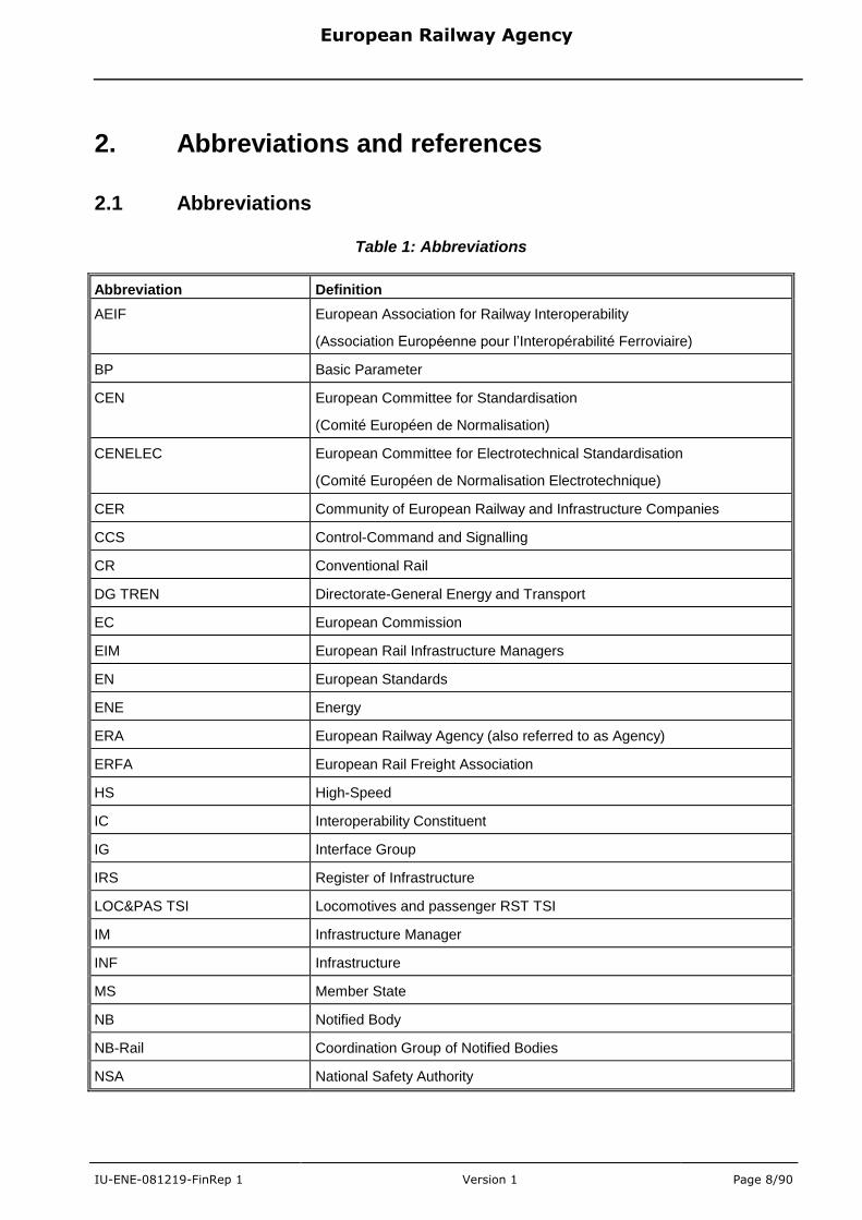
2.1 Abbreviations
Table 1: Abbreviations
Abbreviation Definition
AEIF European Association for Railway Interoperability
(Association Européenne pour l‟Interopérabilité Ferroviaire)
BP Basic Parameter
CEN European Committee for Standardisation
(Comité Européen de Normalisation)
CENELEC European Committee for Electrotechnical Standardisation
(Comité Européen de Normalisation Electrotechnique)
CER Community of European Railway and Infrastructure Companies
CCS Control-Command and Signalling
CR Conventional Rail
DG TREN Directorate-General Energy and Transport
EC European Commission
EIM European Rail Infrastructure Managers
EN European Standards
ENE Energy
ERA European Railway Agency (also referred to as Agency)
ERFA European Rail Freight Association
HS High-Speed
IC Interoperability Constituent
IG Interface Group
IRS Register of Infrastructure
LOC&PAS TSI Locomotives and passenger RST TSI
IM Infrastructure Manager
INF Infrastructure
MS Member State
NB Notified Body
NB-Rail Coordination Group of Notified Bodies
NSA National Safety Authority
European Railway Agency
IU-ENE-081219-FinRep 1 Version 1 Page 9/90
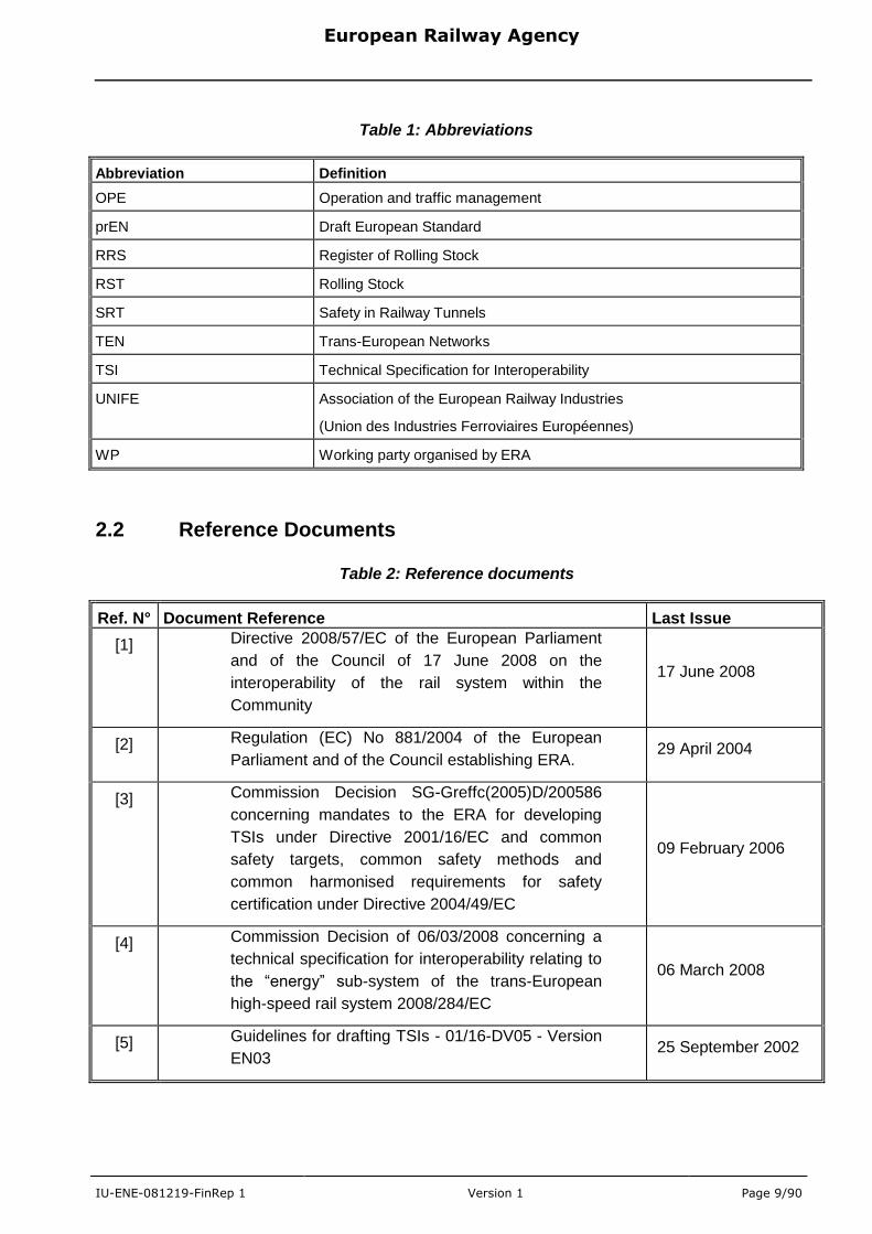
Table 1: Abbreviations
Abbreviation Definition
OPE Operation and traffic management
prEN Draft European Standard
RRS Register of Rolling Stock
RST Rolling Stock
SRT Safety in Railway Tunnels
TEN Trans-European Networks
TSI Technical Specification for Interoperability
UNIFE Association of the European Railway Industries
(Union des Industries Ferroviaires Européennes)
WP Working party organised by ERA
2.2 Reference Documents
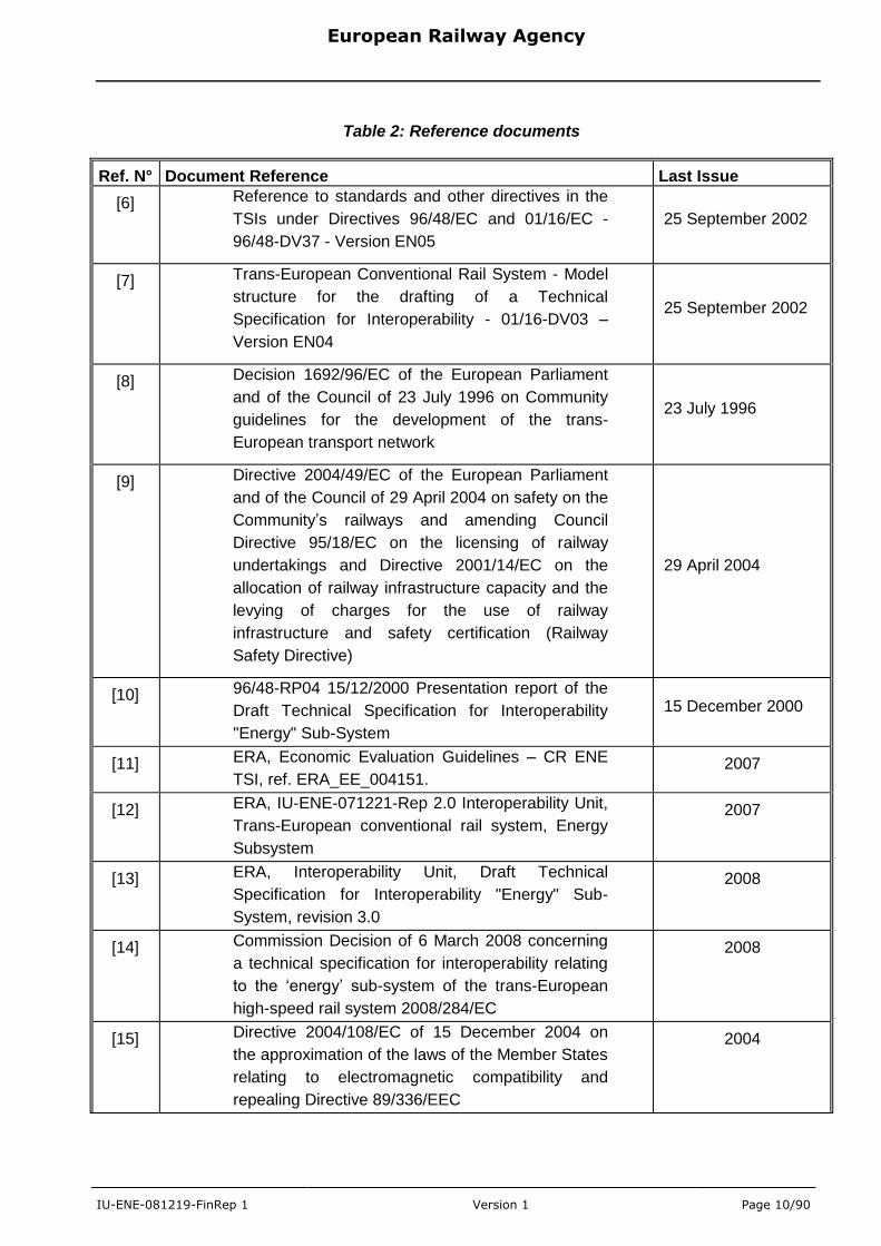
Table 2: Reference documents
Ref. N° Document Reference Last Issue
[1] Directive 2008/57/EC of the European Parliament
and of the Council of 17 June 2008 on the
interoperability of the rail system within the
Community
17 June 2008
[2] Regulation (EC) No 881/2004 of the European
Parliament and of the Council establishing ERA. 29 April 2004
[3] Commission Decision SG-Greffc(2005)D/200586
concerning mandates to the ERA for developing
TSIs under Directive 2001/16/EC and common
safety targets, common safety methods and
common harmonised requirements for safety
certification under Directive 2004/49/EC
09 February 2006
[4] Commission Decision of 06/03/2008 concerning a
technical specification for interoperability relating to
the “energy” sub-system of the trans-European
high-speed rail system 2008/284/EC
06 March 2008
[5] Guidelines for drafting TSIs - 01/16-DV05 - Version
EN03 25 September 2002
European Railway Agency
IU-ENE-081219-FinRep 1 Version 1 Page 10/90
Table 2: Reference documents
Ref. N° Document Reference Last Issue
[6] Reference to standards and other directives in the
TSIs under Directives 96/48/EC and 01/16/EC -
96/48-DV37 - Version EN05
25 September 2002
[7] Trans-European Conventional Rail System - Model
structure for the drafting of a Technical
Specification for Interoperability - 01/16-DV03 –
Version EN04
25 September 2002
[8] Decision 1692/96/EC of the European Parliament
and of the Council of 23 July 1996 on Community
guidelines for the development of the trans-
European transport network
23 July 1996
[9] Directive 2004/49/EC of the European Parliament
and of the Council of 29 April 2004 on safety on the
Community‟s railways and amending Council
Directive 95/18/EC on the licensing of railway
undertakings and Directive 2001/14/EC on the
allocation of railway infrastructure capacity and the
levying of charges for the use of railway
infrastructure and safety certification (Railway
Safety Directive)
29 April 2004
[10] 96/48-RP04 15/12/2000 Presentation report of the
Draft Technical Specification for Interoperability
"Energy" Sub-System
15 December 2000
[11] ERA, Economic Evaluation Guidelines – CR ENE
TSI, ref. ERA_EE_004151. 2007
[12] ERA, IU-ENE-071221-Rep 2.0 Interoperability Unit,
Trans-European conventional rail system, Energy
Subsystem
2007
[13] ERA, Interoperability Unit, Draft Technical
Specification for Interoperability "Energy" Sub-
System, revision 3.0
2008
[14] Commission Decision of 6 March 2008 concerning
a technical specification for interoperability relating
to the „energy‟ sub-system of the trans-European
high-speed rail system 2008/284/EC
2008
[15] Directive 2004/108/EC of 15 December 2004 on
the approximation of the laws of the Member States
relating to electromagnetic compatibility and
repealing Directive 89/336/EEC
2004
European Railway Agency
IU-ENE-081219-FinRep 1 Version 1 Page 11/90
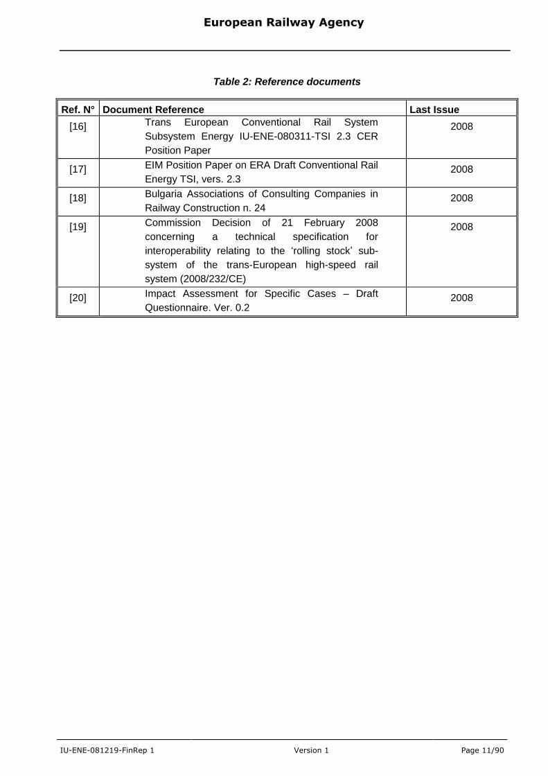
Table 2: Reference documents
Ref. N° Document Reference Last Issue
[16] Trans European Conventional Rail System
Subsystem Energy IU-ENE-080311-TSI 2.3 CER
Position Paper
2008
[17] EIM Position Paper on ERA Draft Conventional Rail
Energy TSI, vers. 2.3 2008
[18] Bulgaria Associations of Consulting Companies in
Railway Construction n. 24 2008
[19] Commission Decision of 21 February 2008
concerning a technical specification for
interoperability relating to the „rolling stock‟ sub-
system of the trans-European high-speed rail
system (2008/232/CE)
2008
[20] Impact Assessment for Specific Cases – Draft
Questionnaire. Ver. 0.2 2008
European Railway Agency
IU-ENE-081219-FinRep 1 Version 1 Page 12/90
3. Working party
3.1 Composition of the WP
The WP has been drawn up following Article 3 of the Agency regulation [2]. The
composition of the WP has not changed since the end of 2007 as reported in
table 3 of the preliminary report [12].
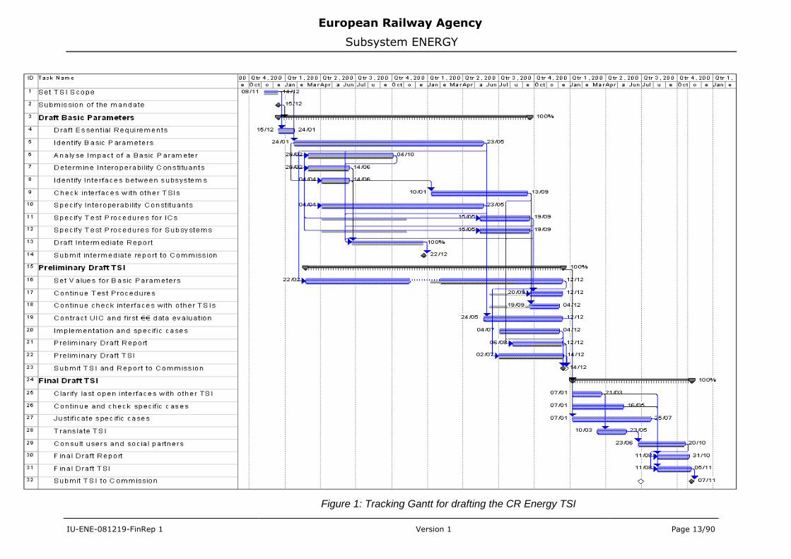
3.2 Time plan
Figure 1 illustrates the actual state of work. It is updated on the original baseline
from beginning of 2006.
The activities in 2008 summarised under the title “Final draft TSI” have been
finalised in time for the TSI and this final report.
European Railway Agency
Subsystem ENERGY
IU-ENE-081219-FinRep 1 Version 1 Page 13/90
Figure 1: Tracking Gantt for drafting the CR Energy TSI
European Railway Agency
Subsystem ENERGY
IU-ENE-081219-FinRep 1 Version 1 Page 14/90
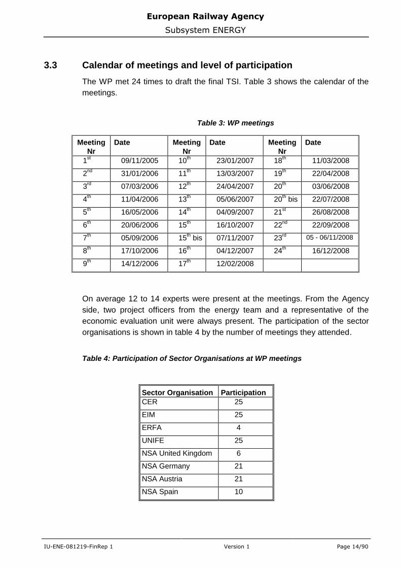
3.3 Calendar of meetings and level of participation
The WP met 24 times to draft the final TSI. Table 3 shows the calendar of the
meetings.
Table 3: WP meetings
Meeting
Nr
Date Meeting
Nr
Date Meeting
Nr
Date
1st 09/11/2005 10
th 23/01/2007 18
th 11/03/2008
2nd
31/01/2006 11th 13/03/2007 19
th 22/04/2008
3rd 07/03/2006 12
th 24/04/2007 20
th 03/06/2008
4th 11/04/2006 13
th 05/06/2007 20
th bis 22/07/2008
5th 16/05/2006 14
th 04/09/2007 21
st 26/08/2008
6th 20/06/2006 15
th 16/10/2007 22
nd 22/09/2008
7th 05/09/2006 15
th bis 07/11/2007 23
rd 05 - 06/11/2008
8th 17/10/2006 16
th 04/12/2007 24
th 16/12/2008
9th 14/12/2006 17
th 12/02/2008
On average 12 to 14 experts were present at the meetings. From the Agency
side, two project officers from the energy team and a representative of the
economic evaluation unit were always present. The participation of the sector
organisations is shown in table 4 by the number of meetings they attended.
Table 4: Participation of Sector Organisations at WP meetings
Sector Organisation Participation
CER 25
EIM 25
ERFA 4
UNIFE 25
NSA United Kingdom 6
NSA Germany 21
NSA Austria 21
NSA Spain 10
European Railway Agency
Subsystem ENERGY
IU-ENE-081219-FinRep 1 Version 1 Page 15/90
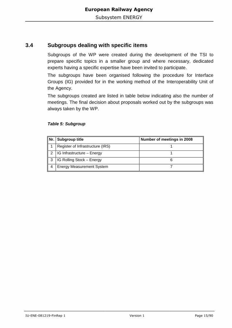
3.4 Subgroups dealing with specific items
Subgroups of the WP were created during the development of the TSI to
prepare specific topics in a smaller group and where necessary, dedicated
experts having a specific expertise have been invited to participate.
The subgroups have been organised following the procedure for Interface
Groups (IG) provided for in the working method of the Interoperability Unit of
the Agency.
The subgroups created are listed in table below indicating also the number of
meetings. The final decision about proposals worked out by the subgroups was
always taken by the WP.
Table 5: Subgroup
Nr. Subgroup title Number of meetings in 2008
1 Register of Infrastructure (IRS) 1
2 IG Infrastructure – Energy 1
3 IG Rolling Stock – Energy 6
4 Energy Measurement System 7
European Railway Agency
Subsystem ENERGY
IU-ENE-081219-FinRep 1 Version 1 Page 16/90
4. Comments on the preliminary report
The report [12] displaying the stage of work at the end of 2007 was delivered to
DG TREN the 21st January 2008.
It was presented thereafter to the 47th
meeting of the Railway Interoperability
and Safety Committee on 14th
February 2008.
The preliminary report was accepted without remarks from MS representatives.
European Railway Agency
Subsystem ENERGY
IU-ENE-081219-FinRep 1 Version 1 Page 17/90
5. Development of the Final Draft TSI
The preliminary draft of CR ENE TSI - version 2.0 - was delivered to the
European Commission and RISC.
Following:
- meetings of working party and dedicated group developing the text about
energy metering,
- meetings with NSAs on elaborating specific cases
- adoption of new interoperability Directive 2008/57 [1]
some modifications were introduced in the course of 2008 to make TSI clearer
(eliminate doubts) and updated (by reference to appropriate articles of new
Directive). Inserted changes are explained in the next clauses. It is also showed
a detailed reference to the essential requirements covered by the CR ENE TSI.
For any further information on specifications already agreed before, please
consult the report [12].
5.1 General changes
5.1.1 Introduction of new Interoperability Directive
The most important change compared to the previous (DIR 2001/16/EC) and
introduced by the new Directive [1], has been the extension of the geographical
scope from TEN to the whole network. This issue is now analysed and will be
taken into account in the next revision of the TSI.
Another modifications referring to energy subsystem are following:
- definitely moving the current collectors to rolling stock subsystem.
Requirements for quality of current collection and assessment methods
were kept in CR ENE TSI.
- introducing on-board parts of the electric energy consumptions measuring
equipment. The issue for the first time appeared as an open point in the
revised HS RST TSI (Commission Decision 2008/284/EC [14]). Now it is
developed in CR LOC&PAS TSI.
5.1.2 Introduction of Decision 2008/768/EC
Decision of the European Parliament and the council on a common framework
for the marketing of products, and repealing Decision 93/465/EEC modified the
modules already applied for conformity assessment of interoperability
constituents and subsystems. The references to the former decision have been
European Railway Agency
Subsystem ENERGY
IU-ENE-081219-FinRep 1 Version 1 Page 18/90
replaced by the new decision and to the technical document developed by ERA
on this issue. According to this the list of Annexes is updated.
5.1.3 Revision of standards
CENELEC is continuing the process of revising the existing standards
according to the progress in technologies and also needs raised during WP
meetings. New versions of norms (at the last stage of approval) were taken into
account in the final draft of the TSI. According to this the reference to EN50119
is updated with the one that will be issued in 2009.
5.1.4 1520/1524 rail system
The special working party was established by ERA for analysing the technical
rules applied by countries using 1520/1524 rail system, particularly former
members of Soviet Union. The issue is crucial for three Baltic States: Estonia,
Latvia and Lithuania which rail systems are still strictly connected with Russia
and other members of Commonwealth of Independent States (CIS). Until
finalization of the work of above-mentioned party the specific cases relating to
these countries were introduced in the TSI in chapter 7 as open points.
5.2 Essential requirements for the Energy subsystem
The essential requirements cover:
- safety,
- reliability and availability,
- health,
- environmental protection,
- technical compatibility.
5.2.1 Safety
According to Annex III to the Directive 2008/57/EC, the essential requirements
for safety are the following:
1.1.1. The design, construction or assembly, maintenance and monitoring of safety-critical components and, more particularly, of the components involved in train movements must be such as to guarantee safety at the level corresponding to the aims laid down for the network, including those for specific degraded situations.
1.1.2. The parameters involved in the wheel/rail contact must meet the stability requirements needed in order to guarantee safe movement at the maximum authorised speed. The parameters of brake equipment must guarantee that it is possible to stop within a given brake distance at the maximum authorised speed.
1.1.3. The components used must withstand any normal or exceptional stresses that have been specified during their period in service. The safety repercussions of any accidental failures must be limited by appropriate means.
European Railway Agency
Subsystem ENERGY
IU-ENE-081219-FinRep 1 Version 1 Page 19/90
1.1.4. The design of fixed installations and rolling stock and the choice of the materials used must be aimed at limiting the generation, propagation and effects of fire and smoke in the event of a fire.
1.1.5. Any devices intended to be handled by users must be so designed as not to impair the safe operation of the devices or the health and safety of users if used in a foreseeable manner, albeit not in accordance with the posted instructions.
The aspects mentioned under 1.1.2 and 1.1.5 are not relevant to the energy
subsystem.
In order to satisfy the essential requirements 1.1.1, 1.1.3 and 1.1.4 above, the
energy subsystem shall be designed and constructed so that the requirements
set out in clauses, 4.2.5 to 4.2.9, 4.2.13 to 4.2.20, 4.4.2, 4.4.3, 4.5, 4.6 and
4.7.2 to 4.7.5 of the TSI are met and the interoperability constituents used
comply with the requirements set out in clause 5.3.1 of the TSI.
The following essential requirement for safety according to Annex III to the
Directive 2008/57/EC [1] is especially of concern for the energy subsystem.
2.2.1. Operation of the energy-supply systems must not impair the safety either of trains or of persons (users, operating staff, trackside dwellers and third parties).
In order to satisfy the essential requirement 2.2.1 above, the energy subsystem
shall be designed and constructed so that the requirements set out in clauses
4.2.5 to 4.2.11, 4.2.19, 4.2.20, 4.4.2, 4.4.3, 4.5, and 4.7.2 to 4.7.6 of the TSI
are met and the interoperability constituents used comply with the requirements
set out in clause 5.3.1.1 to 5.3.1.4 and 5.3.1.6 of the TSI.
5.2.2 Reliability & availability
According to Annex III to the Directive 2008/57/EC [1], the essential
requirements for reliability and availability are the following:
1.2. The monitoring and maintenance of fixed or movable components that are involved in train movements must be organised, carried out and quantified in such a manner as to maintain their operation under the intended conditions.
In order to satisfy the essential requirement 1.2, the energy subsystem shall be
maintained such that the requirements set out in clause 4.2.5, 4.4.2, 4.4.3 and
4.5 of the TSI are met.
5.2.3 Health
According to Annex III to the Directive 2008/57/EC [1], the essential
requirements for health are the following:
1.3.1. Materials likely, by virtue of the way they are used, to constitute a health hazard to those having access to them must not be used in trains and railway infrastructures.
1.3.2. Those materials must be selected, deployed and used in such a way as to restrict the emission of harmful and dangerous fumes or gases, particularly in the event of fire.
European Railway Agency
Subsystem ENERGY
IU-ENE-081219-FinRep 1 Version 1 Page 20/90
In order to satisfy the essential requirements 1.3.1 and 1.3.2, the energy
subsystem shall be designed and constructed so that the requirements set out
in clauses 4.2.18, 4.5, 4.7.2 to 4.7.5 of the TSI are met and the interoperability
constituents used comply with the requirements set out in clause 5.3.1.7 of the
TSI.
5.2.4 Environmental protection
According to Annex III to the Directive 2008/57/EC [1], the essential
requirements for environmental protection are the following:
1.4.1. The environmental impact of establishment and operation of the rail system must be assessed and taken into account at the design stage of the system in accordance with the Community provisions in force.
1.4.2. The materials used in the trains and infrastructures must prevent the emission of fumes or gases which are harmful and dangerous to the environment, particularly in the event of fire.
1.4.3. The rolling stock and energy-supply systems must be designed and manufactured in such a way as to be electromagnetically compatible with the installations, equipment and public or private networks with which they might interfere.
1.4.4. Operation of the rail system must respect existing regulations on noise pollution.
1.4.5. Operation of the rail system must not give rise to an inadmissible level of ground vibrations for the activities and areas close to the infrastructure and in a normal state of maintenance.
The aspects mentioned under 1.4.4 and 1.4.5 are not relevant to the Energy
subsystem.
In order to satisfy essential requirements 1.4.1 to 1.4.3 the energy subsystem
shall be designed and constructed so that the requirements set out in clauses
4.2.7, 4.2.9 to 4.2.12, 4.2.16, 4.2.18 to 4.2.20 and 4.7.2 to 4.7.5 of the TSI are
met and the interoperability constituents used comply with the requirements set
out in clauses 5.3.1.1, 5.3.1.3 to 5.3.1.5 of the TSI.
The following essential requirement for environmental protection according to
Annex III to the Directive 2008/57/EC [1] is especially of concern for the energy
subsystem.
2.2.2. The functioning of the electrical or thermal energy-supply systems must not interfere with the environment beyond the specified limits.
In order to satisfy essential requirement 2.2.2 the energy subsystem shall be
designed and constructed so that the requirements set out in clauses 4.2.11,
4.2.12, 4.2.16 and 4.7.2 to 4.7.5 of the TSI are met and the interoperability
constituents used comply with the requirements set out in clauses 5.3.1.1,
5.3.1.3 and 5.3.1.4 of the TSI.
European Railway Agency
Subsystem ENERGY
IU-ENE-081219-FinRep 1 Version 1 Page 21/90
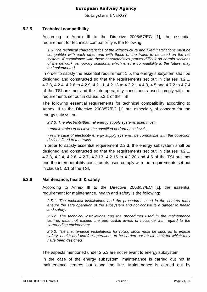
5.2.5 Technical compatibility
According to Annex III to the Directive 2008/57/EC [1], the essential
requirement for technical compatibility is the following:
1.5. The technical characteristics of the infrastructure and fixed installations must be compatible with each other and with those of the trains to be used on the rail system. If compliance with these characteristics proves difficult on certain sections of the network, temporary solutions, which ensure compatibility in the future, may be implemented.
In order to satisfy the essential requirement 1.5, the energy subsystem shall be
designed and constructed so that the requirements set out in clauses 4.2.1,
4.2.3, 4.2.4, 4.2.6 to 4.2.9, 4.2.11, 4.2.13 to 4.2.21, 4.4.3, 4.5 and 4.7.2 to 4.7.4
of the TSI are met and the interoperability constituents used comply with the
requirements set out in clause 5.3.1 of the TSI.
The following essential requirements for technical compatibility according to
Annex III to the Directive 2008/57/EC [1] are especially of concern for the
energy subsystem.
2.2.3. The electricity/thermal energy supply systems used must:
- enable trains to achieve the specified performance levels,
- in the case of electricity energy supply systems, be compatible with the collection devices fitted to the trains.
In order to satisfy essential requirement 2.2.3, the energy subsystem shall be
designed and constructed so that the requirements set out in clauses 4.2.1,
4.2.3, 4.2.4, 4.2.6, 4.2.7, 4.2.13, 4.2.15 to 4.2.20 and 4.5 of the TSI are met
and the interoperability constituents used comply with the requirements set out
in clause 5.3.1 of the TSI.
5.2.6 Maintenance, health & safety
According to Annex III to the Directive 2008/57/EC [1], the essential
requirement for maintenance, health and safety is the following:
2.5.1. The technical installations and the procedures used in the centres must ensure the safe operation of the subsystem and not constitute a danger to health and safety.
2.5.2. The technical installations and the procedures used in the maintenance centres must not exceed the permissible levels of nuisance with regard to the surrounding environment.
2.5.3. The maintenance installations for rolling stock must be such as to enable safety, health and comfort operations to be carried out on all stock for which they have been designed.
The aspects mentioned under 2.5.3 are not relevant to energy subsystem.
In the case of the energy subsystem, maintenance is carried out not in
maintenance centres but along the line. Maintenance is carried out by
European Railway Agency
Subsystem ENERGY
IU-ENE-081219-FinRep 1 Version 1 Page 22/90
maintenance units, for which the requirements mentioned under 2.5.1 and 2.5.2
apply. In order to satisfy the above mentioned essential requirements, the
energy subsystem shall be designed and constructed so that the requirements
set out in clauses 4.2.12, 4.5, 4.7.5 and 4.7.6 of the TSI are met.
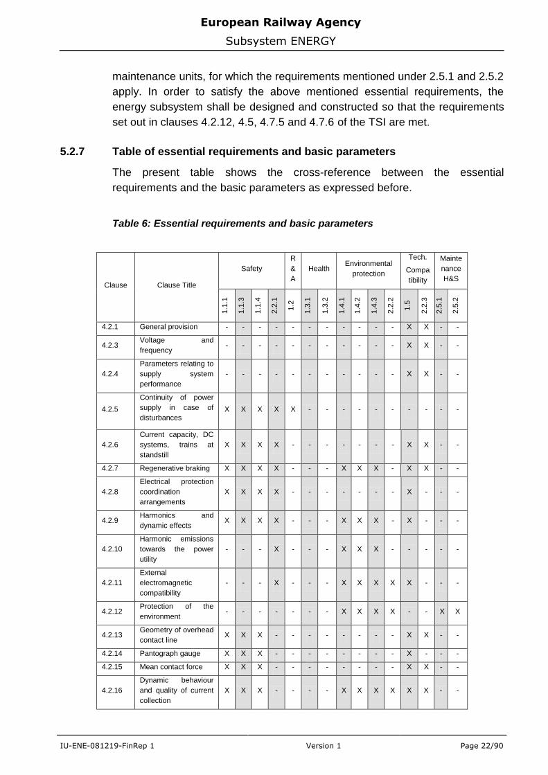
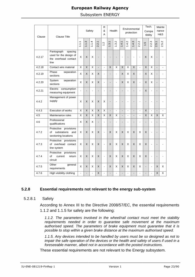
5.2.7 Table of essential requirements and basic parameters
The present table shows the cross-reference between the essential
requirements and the basic parameters as expressed before.
Table 6: Essential requirements and basic parameters
Clause Clause Title
Safety
R
&
A
Health Environmental
protection
Tech.
Compa
tibility
Mainte
nance
H&S
1.1
.1
1.1
.3
1.1
.4
2.2
.1
1.2
1.3
.1
1.3
.2
1.4
.1
1.4
.2
1.4
.3
2.2
.2
1.5
2.2
.3
2.5
.1
2.5
.2
4.2.1 General provision - - - - - - - - - - - X X - -
4.2.3 Voltage and
frequency - - - - - - - - - - - X X - -
4.2.4
Parameters relating to
supply system
performance
- - - - - - - - - - - X X - -
4.2.5
Continuity of power
supply in case of
disturbances X X X X X - - - - - - - - - -
4.2.6
Current capacity, DC
systems, trains at
standstill
X X X X - - - - - - - X X - -
4.2.7 Regenerative braking X X X X - - - X X X - X X - -
4.2.8
Electrical protection
coordination
arrangements
X X X X - - - - - - - X - - -
4.2.9 Harmonics and
dynamic effects X X X X - - - X X X - X - - -
4.2.10
Harmonic emissions
towards the power
utility
- - - X - - - X X X - - - - -
4.2.11
External
electromagnetic
compatibility
- - - X - - - X X X X X - - -
4.2.12 Protection of the
environment - - - - - - - X X X X - - X X
4.2.13 Geometry of overhead
contact line X X X - - - - - - - - X X - -
4.2.14 Pantograph gauge X X X - - - - - - - - X - - -
4.2.15 Mean contact force X X X - - - - - - - - X X - -
4.2.16
Dynamic behaviour
and quality of current
collection
X X X - - - - X X X X X X - -
European Railway Agency
Subsystem ENERGY
IU-ENE-081219-FinRep 1 Version 1 Page 23/90
Clause Clause Title
Safety
R
&
A
Health Environmental
protection
Tech.
Compa
tibility
Mainte
nance
H&S
1.1
.1
1.1
.3
1.1
.4
2.2
.1
1.2
1.3
.1
1.3
.2
1.4
.1
1.4
.2
1.4
.3
2.2
.2
1.5
2.2
.3
2.5
.1
2.5
.2
4.2.17
Pantograph spacing
used for the design of
the overhead contact
line
X X X - - - - - - - - X X - -
4.2.18 Contact wire material X X X - - X X X X X - X X - -
4.2.19 Phase separation
sections X X X X - - - X X X - X X - -
4.2.20 System separation
sections X X X X - - - X X X - X X - -
4.2.21 Electric consumption
measuring equipment - - - - - - - - - - - X - - -
4.4.2
Management of power
supply X X X X X - - - - - - - - - -
4.4.3 Execution of works X X X X X - - - - - - X - - -
4.5 Maintenance rules X X X X X X X - - - - X X X X
4.6 Professional
qualifications X X X - - - - - - - - - - - -
4.7.2
Protective provisions
of substations and
sectioning locations
X X X X - X X X X X X X - - -
4.7.3
Protective provisions
of overhead contact
line system
X X X X - X X X X X X X - - -
4.7.4
Protective provisions
of current return
circuit
X X X X - X X X X X X X - - -
4.7.5 Other general
requirements X X X X - X X X X X X - - X X
4.7.6 High visibility clothing - - - X - - - - - - - - - X X
5.2.8 Essential requirements not relevant to the energy sub-system
5.2.8.1 Safety
According to Annex III to the Directive 2008/57/EC, the essential requirements
1.1.2 and 1.1.5 for safety are the following:
1.1.2. The parameters involved in the wheel/rail contact must meet the stability requirements needed in order to guarantee safe movement at the maximum authorised speed. The parameters of brake equipment must guarantee that it is possible to stop within a given brake distance at the maximum authorised speed.
1.1.5. Any devices intended to be handled by users must be so designed as not to impair the safe operation of the devices or the health and safety of users if used in a foreseeable manner, albeit not in accordance with the posted instructions.
These essential requirements are not relevant to the Energy subsystem.
European Railway Agency
Subsystem ENERGY
IU-ENE-081219-FinRep 1 Version 1 Page 24/90
5.2.8.2 Environmental protection
According to Annex III to the Directive 2008/57/EC, the essential requirements
1.4.4 and 1.4.5 for environmental protection are the following:
1.4.4. Operation of the rail system must respect existing regulations on noise pollution.
1.4.5. Operation of the rail system must not give rise to an inadmissible level of ground vibrations for the activities and areas close to the infrastructure and in a normal state of maintenance.
These essential requirements are not relevant to the Energy subsystem.
5.2.8.3 Maintenance, health & safety
According to Annex III to the Directive 2008/57/EC, the essential requirement
2.5.3 for maintenance, health and safety is the following:
2.5.3. The maintenance installations for rolling stock must be such as to enable safety, health and comfort operations to be carried out on all stock for which they have been designed.
This essential requirement is not relevant to energy subsystem.
5.3 Description of the Energy Subsystem
5.3.1 Parameters relating to supply system performance (clause 4.2.4 of the
TSI)
The changes refer to the common agreement achieved during interface
meetings between rolling stock and energy working parties. In case of
requirements for the power factor, the new Annex G (and reference to clause
6.3 of EN50388:2005) has been introduced (instead of former reference to
clause 6.2 of EN50388:2005) which clarified the problem of trains in yards and
sidings.
5.3.2 Continuity of power supply in case of disturbances in tunnels (clause
4.2.5 of the TSI)
The scope of this clause is now strictly limited to the interface with the clause
4.2.3.1 of CR SRT TSI.
5.3.3 Current capacity, DC systems, trains at standstill (clause 4.2.6 of the TSI)
In order to close an open point (referring to temperature limits for OCL) from the
revised HS ENE TSI, the new clause – developed based on the revision of the
EN50119:2001 – has been adopted as Annex F. Because of the fact that the
new version of the norm will be issued in 2009, the text has been updated by
making the reference to EN50119:2009 clause 5.1.2.
European Railway Agency
Subsystem ENERGY
IU-ENE-081219-FinRep 1 Version 1 Page 25/90
5.3.4 Regenerative braking (clause 4.2.7 of the TSI)
Compare to the HS ENE TSI, to make step forward in reduction of energy
consumption for DC systems, the requirement has been put to permit the use of
regenerative braking at least by exchanging power with other trains.
The problem of the refusal of energy from regenerative braking by the supplier
raised by NoBo was taken into account by introducing the relevant information
in the Register of Infrastructure.
5.3.5 Electrical protection coordination arrangements (clause 4.2.8 of the TSI)
Following the interface meetings with rolling stock working party and meetings
on specific cases, the reference to EN50388:2005 has been amended by
introducing the Annex H. This Annex contained the modified table for breakers
tripping sequence - developed during revision process of EN50388:2005 –
which explained doubts aroused during the application of the former HS TSI.
5.3.6 Harmonic and dynamic effects for AC system (clause 4.2.9 of the TSI)
This aspect is very important for AC systems and it is connected with the
introduction of power electronic equipment in vehicles and supply systems and
its impact on existing rolling stock and infrastructure. Following remarks from
MS and meetings with rolling stock group, the text has been adapted to be
clearer.
5.3.7 External electromagnetic compatibility (clause 4.2.11 of the TSI)
This problem is not a specific characteristic of the rail network. Railway energy
supply installations shall comply with European regulations. Previous reference
to European standard EN50121-2:2006 has been replaced by reference to
EMC Directive 2004/108/EC [15].
5.3.8 Geometry of the overhead contact line - Contact wire height (clause
4.2.13.1 of the TSI)
In order to make the text clearer, the Annex J has been added with a figure
describing different contact wire and pantograph working heights, definitions
and the relations between them. Because of the fact that the new version of the
norm will be issued in 2009, the text has been updated by making the reference
to EN50119:2009 figure 1.
5.3.9 Geometry of the overhead contact line - Lateral deviation (clause 4.2.13.3
of the TSI)
The lateral deviation of the overhead contact line is a parameter related to the
pantograph head profile defined in the CR LOC&PAS TSI. Previous reference
European Railway Agency
Subsystem ENERGY
IU-ENE-081219-FinRep 1 Version 1 Page 26/90
(for calculation of lateral deviation) to the standard EN50367 Annex A.3 – which
was applied in HS ENE TSI - has been questioned during interface meetings
with INF, RST group as not applicable to CR and 1950 mm pantograph profile.
In the mean time, CEN - basing on UIC leaflets referring to gauge - has been
developed new series of standard prEN15273 covering aspects relating to
gauge (see also clause 5.1.10). The prEN15273 clause containing the
calculation of the pantograph gauge, has been adopted as Annex E and to be
complementary to clause 4.2.14 (Pantograph gauge) of CR ENE TSI, the
clause E.4 has been inserted, explaining references between lateral deviation
and pantograph profiles, vehicle movement and track tolerances.
After consultation period, CER raised a proposal to modify the approach to the
compatibility between pantograph profile and OCL taking into account the
advantages given by the Annex E. Instead of lateral deviation as a basic
parameter it has been suggested: maximum position of the contact wire on
pantograph collector head. This is in line with different design rules applied by
MS and it would relax the requirements for design parameter. However this
issue which has been considered positively by the WP, implies a significant
change in the requirements for the geometry of the OCL. For that reason, ERA
is preparing a questionnaire addressing the problem, which will give a good
basis for farther investigations that will have to be taken into account in future
revisions of TSI.
5.3.10 Pantograph gauge (clause 4.2.14 of the TSI)
This clause and the corresponding Annex E have been modified. As a basis,
the prEN15273-3 clause 11 (referring to pantograph gauge) has been used,
applying the same methodology for calculations. Unfortunately the terminology
used by CEN standard was in contradiction to wording already applied by
CENELEC standards (like EN50367:2006, EN50119:2009, 50206-1:1998). The
problem has been highlighted in previous reports. To make it clear new figures
have been added in the Annex E.
5.3.11 Dynamic behavior and quality of current collection (clause 4.2.16 of the
TSI)
The current collection quality is the evidence of the design and installation
quality for both interoperability constituents (overhead contact line and
pantograph) and has an impact on their lifetime and also on assessment of
both subsystems: energy and rolling stock.
In case of the conventional rail, the number and the arrangements of the
pantographs (see also clause 4.2.17) being in simultaneous contact with
overhead contact line, have to be taken into account during the process of
assessment.
European Railway Agency
Subsystem ENERGY
IU-ENE-081219-FinRep 1 Version 1 Page 27/90
Additionally to facilitate and accelerate the process of certification of new
constituents – in case of new products – the possibility to perform common
tests of both elements: new type of OCL and new type of pantograph, has been
added. This issue is very important for MSs not having already accepted ICs
which were assessed against to HS TSI.
Accordingly, the previous version of conformity assessment clauses has been
adapted and clarified.
5.3.12 Pantograph spacing (clause 4.2.17 of the TSI)
Pantograph arrangement has a fundamental impact on the design of the OCL
and the quality of current collection. In case of conventional rail the variety of
possible combinations of raised pantographs is much wider than in high speed
rail system. To take into account different local conditions and needs, in the
table 4.2.17, new possible pantograph spacing design values were added. It
gives possibility for IM to choose the proper design, based on the business
ground. It is also an indication for operators on which possible combination of
raised pantographs is acceptable without additional tests.
5.3.13 Contact wire material (clause 4.2.18 of the TSI)
The changes, made in this clause, refer to the discussion during the interface
meetings with rolling stock group and reflect the development of corresponding
clause in CR LOC&PAS TSI setting requirements for material for contact strips.
In this clause there is a reference to EN50149:2001 which is now under revision
(see Table 7).
5.3.14 Electric consumption measuring equipment (clause 4.2.21 of the TSI)
This clause has been added after the introduction of requirements for on-board
part electric consumption measuring equipment in clause 4.2.8.2.8 of
LOC&PAS CR TSI (Energy consumption measuring function). The aim of this
clause is to assure the compatibility of the on-board part with track-side system
in case that the on-board measuring equipment is required by energy supplier.
5.3.15 Functional and technical specifications of the interfaces (clause 4.3 of the
TSI)
In course of the year 2008, the interface meetings with infrastructure and rolling
stock were continued (see §3.4). As a result from those meetings, the adequate
changes were introduced in the relevant clauses and tables.
Detailed information on modifications done in comparison to the text of TSI sent
for consultation, are given in clauses 5.3.1-14.
European Railway Agency
Subsystem ENERGY
IU-ENE-081219-FinRep 1 Version 1 Page 28/90
5.4 Interoperability Constituents (Chapter 5 of the TSI)
The adoption of new Directive 2008/57 [1] has definitely moved the pantograph
to the rolling stock subsystem. As a result the only interoperability constituent
for energy subsystem remains the overhead contact line.
More explanations on reasons and decisions taken during discussions on
interoperability constituents were given in the report [12].
5.5 Assessment of Conformity (Chapter 6 of the TSI)
The chapter has been reviewed by the Conformity Survey Group (CSG).
CSG recommended deleting the section 6.2.3 „Assessment of maintenance
subsystem‟ of the preliminary draft TSI, because this no longer exists as a
separate structural subsystem. The clause 6.4 `The certification of subsystems
containing non-certified Interoperability Constituents during the transition
period` has been modified according to ERA proposals submitted to the
Railway Interoperability and Safety Committee.
Other changes to particular clauses are given below.
5.5.1 Existing solutions for Interoperability Constituents (clause 6.1.2.2 of the
TSI)
In case of existing solutions, CSG recommended to replace the module A1
Internal design control with product verification by module A Internal production
control, which gives to the manufacture right to issue the declaration of
conformity for the interoperability constituent by himself, without involvement of
NoBo.
5.5.2 Application of modules (clause 6.2.2 of the TSI)
The topic referring to the introduction of the new Decision 2008/768/EC [1] was
highlighted in clause 5.1.2. On this base ERA is preparing a technical document
containing the new modules which will cover both IC and subsystem
assessment.
5.6 Implementation of the Energy TSI (Chapter 7 of the TSI)
5.6.1 Introduction
The broader overview on the implementation issue was given in the previous
report [12]. The following clause only explains introduced changes.
European Railway Agency
Subsystem ENERGY
IU-ENE-081219-FinRep 1 Version 1 Page 29/90
5.6.2 Existing subsystem that are not subject to a renewal or upgrading project
(clause 7.4.4 of the TSI)
The idea of creating a new module SA1 for assessment of existing subsystems
has been finally abandoned, due to legal aspects.
However it has to be considered that the possibility of building new energy
subsystems (it refers also to other „infrastructure‟ subsystems), compare to HS
network is relatively small.
Also upgrading and renewals in the sense of the Directive are limited due to the
fact that CR network is a “living organism” so changes are introduced with, as
little as possible, disruptions to the traffic. In this case the implementation of the
TSI would be postponed to the distant future. To speed up the process and give
the opportunity to IM to declare that existing subsystem is compatible with TSI
requirements, a new clause has been introduced: an IM can - on voluntary basis
- complete the Register of Infrastructure to show the compliance with the basic
parameters of the TSI.
European Railway Agency
Subsystem ENERGY
IU-ENE-081219-FinRep 1 Version 1 Page 30/90
6. Consultation
6.1 Introduction
After delivering the preliminary draft of the TSI to the RIS Committee the text
was translated into French and German. On 23rd of June 2008 the document
was sent to social partners for comments. Due to the holiday period the final
date for delivering response were defined on 20 of October 2008. The following
table indicates the organisations and types of comments received.
Table 7: Opinions issued concerning the preliminary CR ENE
TSI
Nr. Association Document
Ref. N°
Type of comments
1 Community of European railway and
infrastructure companies (CER)
[16] General remarks
Detail and editorial comments
2 European rail infrastructure
managers (EIM)
[17] General remarks
Detail and editorial comments
3 Bulgarian association of consulting
companies in railway construction
(BACCRC)
[18] Detail comments
During 23rd
meeting of WP in November 2008 the remarks were discussed. The
general comments are described in the clauses below.
6.2 Structure of common clauses of different TSIs
CER, in its position paper, indicates the need of keeping the same structure of
different TSIs, particularly clauses which are common for all TSIs. After internal
discussions the final draft of TSI has been checked accordingly.
6.3 Interfaces between the subsystems
This issue was raised in both position papers: CER and EIM.
The energy subsystem has a lot of interfaces with rolling stock one.
The concerns were expressed on different timescale of drafting energy and
rolling stock TSI, which could create discrepancies in requirements. To this end
the interface document has been prepared summarising the clauses of
LOC&PAS and INF TSI which refer to relevant clauses in ENE TSI.
European Railway Agency
Subsystem ENERGY
IU-ENE-081219-FinRep 1 Version 1 Page 31/90
6.4 EU 1520/1524 rail system
CER position paper indicated the problem of putting the requirements for
1520/1524 system together with requirements for the standard gauge in current
TSI. The issue, in case of ENE TSI, refers only to Baltic States: Estonia, Latvia
and Lithuania which rail system is still strictly connected with CIS countries and
railway national rules are in line with rules generally applied in the former Soviet
Union. As a solution, suggested by CER, all three MSs are addressed in clause
referring to Specific Cases (see also clause 7.3 of this report).
Other countries, used different from 1435 mm gauge track, follow EN norms.
6.5 Existing subsystem that has not been subject to a renewal or
upgrading project
This issue is common for all „fixed‟ subsystems, but particularly important for
infrastructure, energy. In the preliminary draft TSI, sent for consultation, there
was a procedure for assessing existing subsystem aiming at a faster way
towards an interoperable network.
CER in its position paper strongly support the idea, underlining the fact that in
the case of CR only few lines are renewed or upgraded or newly built and on
the other hand many lines already today fulfil TSI requirements without the
need for any project.
The problem was long discussed internally but according to current regulations
there is no legal support for keeping this solution.
Finally this procedure was withdrawn from the text of the TSI (see also clause
5.6.2 of this report).
6.6 Energy metering
Both – CER and EIM – position papers expressed the need for developing
requirements for energy metering. According to Annex II clause 2.2 of the new
interoperability Directive [1] on-board part electric consumption measuring
equipment is included into the energy subsystem and the relevant clause has
been put in the LOC&PAS CR TSI (see clause 9.1 of this report).
CER, cited also this point from the Directive, suggested to extent the scope
covering also track-side installation and data exchange between IM and train
operator. However this proposal significantly exceeds current legal provisions –
Directive clearly indicates „on-board part‟. Apart from this aspects mentioned by
CER are now under the elaboration of dedicated UIC groups preparing relevant
leaflet.
European Railway Agency
Subsystem ENERGY
IU-ENE-081219-FinRep 1 Version 1 Page 32/90
6.7 Other remarks
As an important aspect CER underlined the problem of translation quality. „The
final translation must be co-ordinated with Member State representatives (native
speakers) before the release to avoid legal and technical errors.
6.8 Detailed comments
Detailed comments have been elaborated during WP meetings.
The results of discussions are given together in the attached final List of
modifications – Annex 1.
European Railway Agency
Subsystem ENERGY
IU-ENE-081219-FinRep 1 Version 1 Page 33/90
7. Specific Cases
7.1 Methodology of the assessment
The request for specific cases was expressed to members of National Safety
Authority network in June 2007. After an analysis of a first set of specific cases
received by the Agency, the assessment methodology was adopted. The
proposed methodology was presented to the NSA during the 10th
plenary
meeting on 20th
February 2008.
On this base a template for precise questionnaire (see Questionnaire [20]) was
created to support the economic evaluation and final acceptance for inclusion in
the TSI or rejection. Each specific case has been analysed taking into account
the following aspects:
addressed basic parameters
specific case – which parameter deviates from TSI requirement
main reasons for requesting a specific case
positive national impact of specific case adoption
expected negative impact of TSI requirement
interfaces to other specific cases within the same TSI
interfaces to other specific cases in other TSI
scope of application
permanent/temporary
conformity assessment
verification body
Detailed explanations of each abovementioned issue are given in the
evaluation questionnaire (see see Questionnaire [20]).
7.2 Assessment of specific cases
7.2.1 Working method
Specific cases need:
To be properly described;
To be technically understood;
To be examined fairly and thoroughly, with a consistent methodology;
European Railway Agency
Subsystem ENERGY
IU-ENE-081219-FinRep 1 Version 1 Page 34/90
To be incorporated into the TSI or rejected, according to the findings gathered.
In order to ensure faire and equal treatment, the Agency had first grouped
specific cases in families, according to the BP(s) concerned. The specific cases
proposed by different MSs and belonging to the same family, were treated
simultaneously, applying the same methodology and the same requirements
(incl. technical and economic data structure).
After receiving the request for the specific case:
MSs have been asked to complete the data in the form provided by the Agency.
National standards and rules that were relevant have been listed by the MS.
The Agency has provided a comparative pre-assessment of the specific cases, considering likely national impact and impact on general aims of TSI.
The WP concerned has been asked to contribute by raising the fundamental
technical questions induced by the specific case. In particular, impacted
interfaces with other subsystems have been listed and described, from a
technical point of view.
The list of national standard and rules (related to the specific cases) has been
reviewed by the Agency. Upon request of the Agency, MSs have facilitated the
access of the Agency to all or part of the listed national rules and standards,
and provided linguistic assistance in this process.
The methodology followed for the analysis was:
verify if there were interfaces with basic parameters of other subsystems caused by the proposed SC, then ensure consistency of the SC with the other necessary SC for the concerned BP;
verify the economic impacts (e.g. maintenance, installation in case of renewal/upgrade of existing installations or new installations) on the concerned subsystem and the concerned interfacing subsystems of the MS (national impact);
analyze if there were negative effects in other member states expected due to the specific case (European impact).

European Railway Agency
Subsystem ENERGY
IU-ENE-081219-FinRep 1 Version 1 Page 35/90
At the end of the process and after important and useful bilateral meetings
between ERA and the concerned MS, each specific case was examined and it
was decided to:
- Include it in the TSI;
or
- Withdrawn it by the MS;
or
- Move it to other TSs.
7.2.2 Status of the Assessment
The requests from Member States for specific cases were submitted to the
Agency in course of 2008.
The Agency prepared for them the relevant questionnaires, and after approval
by the MS, it was published into the ERA`s website to respect the principal of
transparency.
This process ended in December 2008.
7.3 Overview of results
The following SCs have been included in the TSI:
- for Baltic States (Estonia, Lithuania and Latvia): the specific cases for the
lines with 1520mm track were considered as an open point;
- for France: the specific case was related to the mean contact force (clause
4.2.15 of TSI) for DC lines with 1.5kV.
- for Finland: a specific case was requested for the nominal contact wire
height 6.15 m (clause 4.2.13.1 of TSI) which is outside the range of
5÷5.75m.
- for UK: for the lines in Great Britain five SCs have been introduced in the
TSI:
Contact wire height (clause 4.2.13.1 of TSI)
Lateral deviation (clause 4.2.13.3 of TSI)
Pantograph gauge (clause 4.2.14 of TSI)
Voltage and frequency (clause 4.2.3 of TSI)
Protective provisions of overhead contact line system (clause 4.7.3 of TSI)
European Railway Agency
Subsystem ENERGY
IU-ENE-081219-FinRep 1 Version 1 Page 36/90
8. Economic evaluation
The present impact assessment summary is common to the impact
assessment report and to the TSI report. For detailed facts and figures, please
consult the body of the impact assessment report.
Overview
The Energy subsystem has become highly standardized at European level, and
we expected the TSI to have, at best, a moderate impact because of wide
voluntary adhesion to the standards. This has proven true for many basic
parameters, and even to the (relatively) new Member States, some of which
embraced CEN / CENELEC standards even before accession.
Key basic parameters
The initial check of basic parameters has highlighted the economic importance
of voltage, frequency, and contact wire displacement in relation with pantograph
head shape.
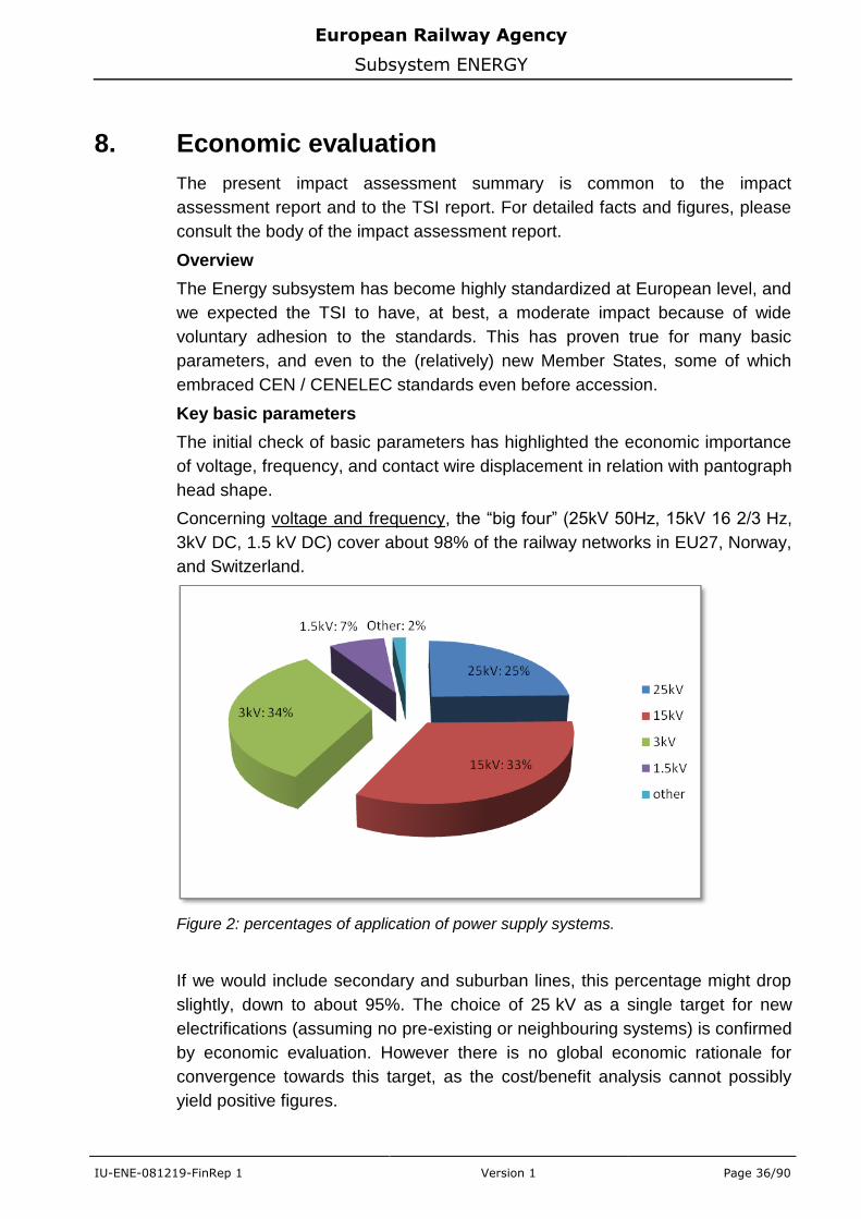
Concerning voltage and frequency, the “big four” (25kV 50Hz, 15kV 16 2/3 Hz,
3kV DC, 1.5 kV DC) cover about 98% of the railway networks in EU27, Norway,
and Switzerland.
Figure 2: percentages of application of power supply systems.
If we would include secondary and suburban lines, this percentage might drop
slightly, down to about 95%. The choice of 25 kV as a single target for new
electrifications (assuming no pre-existing or neighbouring systems) is confirmed
by economic evaluation. However there is no global economic rationale for
convergence towards this target, as the cost/benefit analysis cannot possibly
yield positive figures.
European Railway Agency
Subsystem ENERGY
IU-ENE-081219-FinRep 1 Version 1 Page 37/90
This overall statement does not exclude the possibility of economically
advantageous migrations on a local scale (e.g. close to borders between
subsystems). Also, the reduction of the number of technical borders inside the
Union or with its neighbours might make migrations towards other systems
(rather than 25 kV) look more attractive.
Overall, the draft TSI preserves the status quo, which is supported by economic
evidence. Unfortunately, the status quo means that rolling stock will need to
further cope with different electrification systems, and the financial burden will
increase with time due to the increase in percentage of multisystem traction
units.
Concerning the contact wire geometric interface with pantographs, antagonistic
design requirements (wide pole spacing vs. short pantographs, also to
accommodate electric gauge) have led to different designs across Europe. The
agreement on one single target (Europantograph) in the high speed Energy TSI
was undermined by a number of significant, permanent specific cases. The
Agency therefore focused on the reduction of the inventory of pantographs
head shapes (currently more than a dozen, including all variants) to two,
namely Europantograph, and the larger shape widely used in Germany, Austria,
Spain and accepted in many more countries. Though these two shapes will
match the two variants of the basic parameter in the Energy TSI, their
acceptance throughout Europe is restricted by one explicit specific case (UK),
and some question marks remain with regards to the acceptance on existing
infrastructure (Italy, Slovenia, Switzerland...).
Miscellaneous
The exclusion of cadmium from the contact wire alloy composition is most
welcome, but has no immediate economic effect, since cadmium is no longer
used in new designs. The benefit here is to nullify the risk of re-introduction of
cadmium.
Assessment of some other key parameters (regeneration, contact strip
material…) will be fully dealt with in the traction units TSI report.
Overall effects of the TSI
As already stated, the proposed TSI applies to a widely standardized, albeit
heterogeneous, subsystem. Its main virtue is to avoid its further drifting apart.
The attempt to reduce the inventory of pantograph head shapes, an explicitly
request from the supply industry, may induce moderate benefits on multisystem
rolling stock. No disbenefits are expected on the infrastructure side.
Another positive aspect is that the benefits of the TSI, however modest, will not
be marred by specific cases, which are few and limited: these specific cases
are essentially caused by insuperable gauge issues (UK, FI), or affect a variant
(1.5 kV) which is of no relevance to future of electrification.
European Railway Agency
Subsystem ENERGY
IU-ENE-081219-FinRep 1 Version 1 Page 38/90
Further benefits may arise from further work on the catenary / pantograph
interface criteria, as suggested by one sector organisation. These could be
brought about by the next revision of the TSI.
European Railway Agency
Subsystem ENERGY
IU-ENE-081219-FinRep 1 Version 1 Page 39/90
9. Closing open points
9.1 Energy consumption measuring devices
The measurement of electric energy consumed by each vehicle is a very
important and complex topic, due to environmental and energy efficiency
concerns.
Some IMs have already introduced computerised settlement systems based on
dedicated measuring equipments installed on the rolling stock
Energy consumption measuring devices were introduced in the revised RST HS
TSI (2008/232/EC [19]) clause 4.2.8.3.5 with a specification as an open point.
To solve the problem a dedicated group was established. A task of that group
was to prepare text which would close this open point in the CR LOC&PAS TSI
clause 4.2.8.2.8.
Additionally new interoperability Directive [1] in Annex II clause 2.2 introduced
on-board parts of the electric consumption measuring equipment as part of the
energy subsystem.
The group has worked with close cooperation with CENELEC WG11 which is
now developing the EN50463 series of standards Railway Applications: Energy
measurement system on board trains.
The provision of an on-board energy measuring system and the use of energy
measuring system based on the on-board measurement of consumed energy is
not mandatory.
If an electric on board energy measuring system is required, it shall be
compatible with CR LOC&PAS TSI clause 4.2.8.2.8 and data provided by this
system shall be accepted for billing.
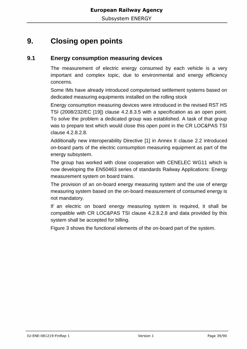
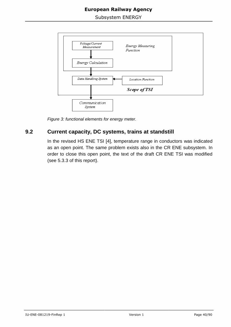
Figure 3 shows the functional elements of the on-board part of the system.
European Railway Agency
Subsystem ENERGY
IU-ENE-081219-FinRep 1 Version 1 Page 40/90
Figure 3: functional elements for energy meter.
9.2 Current capacity, DC systems, trains at standstill
In the revised HS ENE TSI [4], temperature range in conductors was indicated
as an open point. The same problem exists also in the CR ENE subsystem. In
order to close this open point, the text of the draft CR ENE TSI was modified
(see 5.3.3 of this report).
European Railway Agency
Subsystem ENERGY
IU-ENE-081219-FinRep 1 Version 1 Page 41/90
10. European Standards
10.1 References in the TSI
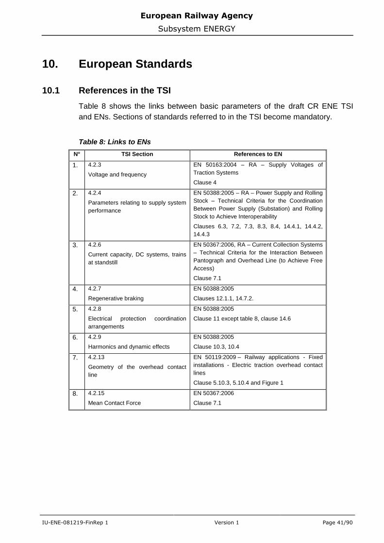
Table 8 shows the links between basic parameters of the draft CR ENE TSI
and ENs. Sections of standards referred to in the TSI become mandatory.
Table 8: Links to ENs
N° TSI Section References to EN
1. 4.2.3
Voltage and frequency
EN 50163:2004 – RA – Supply Voltages of
Traction Systems
Clause 4
2. 4.2.4
Parameters relating to supply system
performance
EN 50388:2005 – RA – Power Supply and Rolling
Stock – Technical Criteria for the Coordination
Between Power Supply (Substation) and Rolling
Stock to Achieve Interoperability
Clauses 6.3, 7.2, 7.3, 8.3, 8.4, 14.4.1, 14.4.2,
14.4.3
3. 4.2.6
Current capacity, DC systems, trains
at standstill
EN 50367:2006, RA – Current Collection Systems
– Technical Criteria for the Interaction Between
Pantograph and Overhead Line (to Achieve Free
Access)
Clause 7.1
4. 4.2.7
Regenerative braking
EN 50388:2005
Clauses 12.1.1, 14.7.2.
5. 4.2.8
Electrical protection coordination
arrangements
EN 50388:2005
Clause 11 except table 8, clause 14.6
6. 4.2.9
Harmonics and dynamic effects
EN 50388:2005
Clause 10.3, 10.4
7. 4.2.13
Geometry of the overhead contact
line
EN 50119:2009 – Railway applications - Fixed
installations - Electric traction overhead contact
lines
Clause 5.10.3, 5.10.4 and Figure 1
8. 4.2.15
Mean Contact Force
EN 50367:2006
Clause 7.1
European Railway Agency
Subsystem ENERGY
IU-ENE-081219-FinRep 1 Version 1 Page 42/90
N° TSI Section References to EN
9. 4.2.16
Dynamic Behaviour and Quality of
Current Collection –
EN 50367:2006
Clause 7.2
EN 50119:2009
Clause 5.2.5.2, 5.10.2
EN 50317:2002 – RA – Current Collection
Systems – Requirements for and Validation of
Measurements of the Dynamic Interaction
Between Pantograph and Overhead Contact Line
EN 50318:2002 RA – Current collection systems
– Validation of simulation of the dynamic inter-
action between pantograph and overhead contact
line
10. 4.2.18
Contact Wire Material
EN 50149:2001, RA – Fixed installations –
Electric traction – Copper and copper alloy
grooved contact wires
Clauses 4.1 to 4.3 and 4.5 to 4.8 (excluding table
1)
11. 4.2.19
Phase Separation Sections
EN 50367:2006
Annex A.1
EN 50388:2005
Clause 5.1
12. 4.2.20
System Separation Sections
EN 50122-2:1998 – RA Fixed Installations – Part
2 Protective Provisions against the effects of stray
currents caused by dc traction systems
Clause 6.1.1
EN 50119:2009
Clause 5.2.10
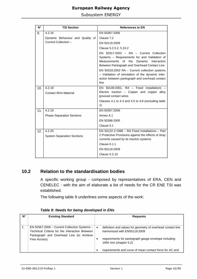
10.2 Relation to the standardisation bodies
A specific working group - composed by representatives of ERA, CEN and
CENELEC - with the aim of elaborate a list of needs for the CR ENE TSI was
established.
The following table 9 underlines some aspects of the work:
Table 9: Needs for being developed in ENs
N° Existing Standard Requests
1. EN 50367:2006 – Current Collection Systems –
Technical Criteria for the Interaction Between
Pantograph and Overhead Line (to Achieve
Free Access)
definition and values for geometry of overhead contact line
harmonized with EN50119:2009
requirements for pantograph gauge envelope including
1950 mm (chapter 5.2)
requirements and curve of mean contact force for AC and
European Railway Agency
Subsystem ENERGY
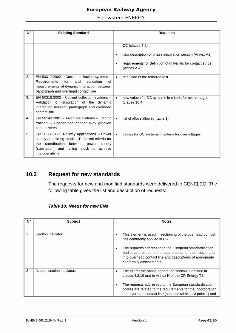
IU-ENE-081219-FinRep 1 Version 1 Page 43/90
N° Existing Standard Requests
DC (clause 7.2)
new description of phase separation section (Annex A1)
requirements for definition of materials for contact strips
(Annex A.4)
2. EN 50317:2002 – Current collection systems –
Requirements for and validation of
measurements of dynamic interaction between
pantograph and overhead contact line
definition of the tethered test
3. EN 50318:2002 - Current collection systems –
Validation of simulation of the dynamic
interaction between pantograph and overhead
contact line
new values for DC systems in criteria for overvoltages
(clause 10.4)
4. EN 50149:2001 – Fixed installations – Electric
traction – Copper and copper alloy grooved
contact wires
list of alloys allowed (table 1)
5. EN 50388:2005 Railway applications – Power
supply and rolling stock – Technical criteria for
the coordination between power supply
(substation) and rolling stock to achieve
interoperability
values for DC systems in criteria for overvoltages
10.3 Request for new standards
The requests for new and modified standards were delivered to CENELEC. The
following table gives the list and description of requests:
Table 10: Needs for new ENs
N° Subject Notes
1 Section insulator This element is used in sectioning of the overhead contact
line commonly applied in CR.
The requests addressed to the European standardisation
bodies are related to the requirements for the incorporation
into overhead contact line and descriptions of appropriate
conformity assessments.
2 Neutral section insulators The BP for the phase separation section is defined in
clause 4.2.19 and in Annex H of the CR Energy TSI.
The requests addressed to the European standardisation
bodies are related to the requirements for the incorporation
into overhead contact line (see also table 11.3 point 1) and
European Railway Agency
Subsystem ENERGY
IU-ENE-081219-FinRep 1 Version 1 Page 44/90
N° Subject Notes
descriptions of appropriate conformity assessments.
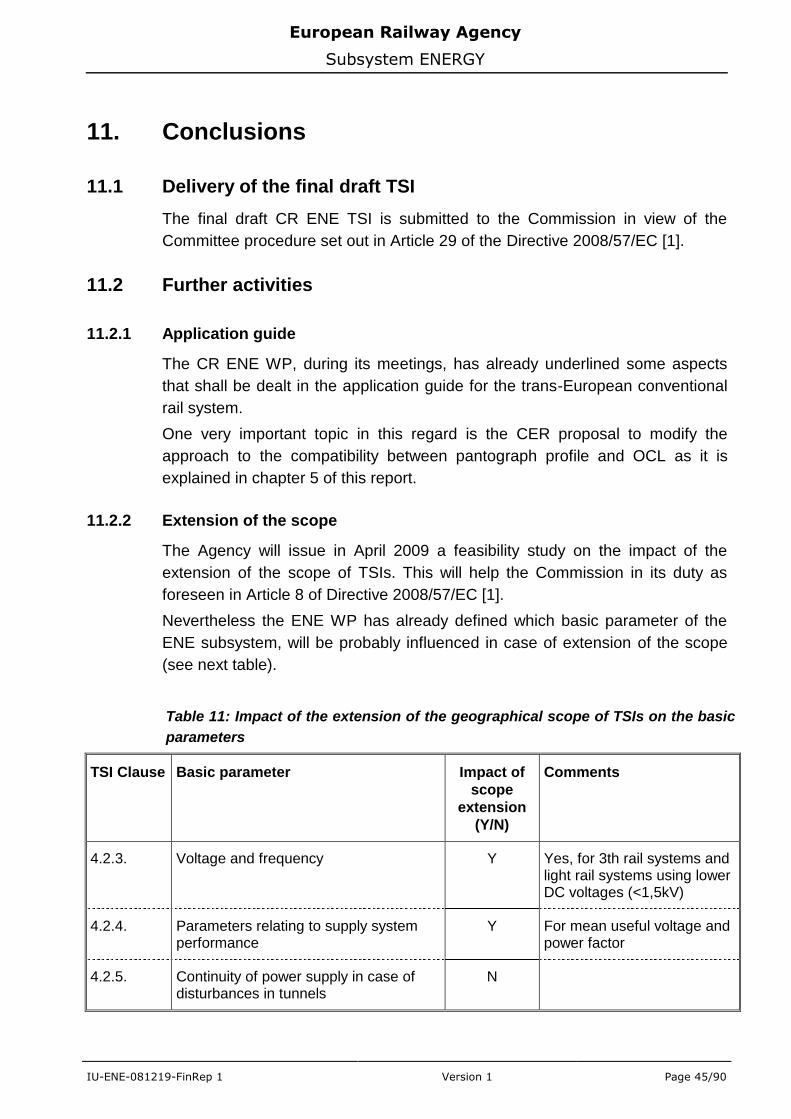
European Railway Agency
Subsystem ENERGY
IU-ENE-081219-FinRep 1 Version 1 Page 45/90
11. Conclusions
11.1 Delivery of the final draft TSI
The final draft CR ENE TSI is submitted to the Commission in view of the
Committee procedure set out in Article 29 of the Directive 2008/57/EC [1].
11.2 Further activities
11.2.1 Application guide
The CR ENE WP, during its meetings, has already underlined some aspects
that shall be dealt in the application guide for the trans-European conventional
rail system.
One very important topic in this regard is the CER proposal to modify the
approach to the compatibility between pantograph profile and OCL as it is
explained in chapter 5 of this report.
11.2.2 Extension of the scope
The Agency will issue in April 2009 a feasibility study on the impact of the
extension of the scope of TSIs. This will help the Commission in its duty as
foreseen in Article 8 of Directive 2008/57/EC [1].
Nevertheless the ENE WP has already defined which basic parameter of the
ENE subsystem, will be probably influenced in case of extension of the scope
(see next table).
Table 11: Impact of the extension of the geographical scope of TSIs on the basic
parameters
TSI Clause Basic parameter Impact of
scope
extension
(Y/N)
Comments
4.2.3. Voltage and frequency Y Yes, for 3th rail systems and light rail systems using lower DC voltages (<1,5kV)
4.2.4. Parameters relating to supply system performance
Y For mean useful voltage and power factor
4.2.5. Continuity of power supply in case of disturbances in tunnels
N
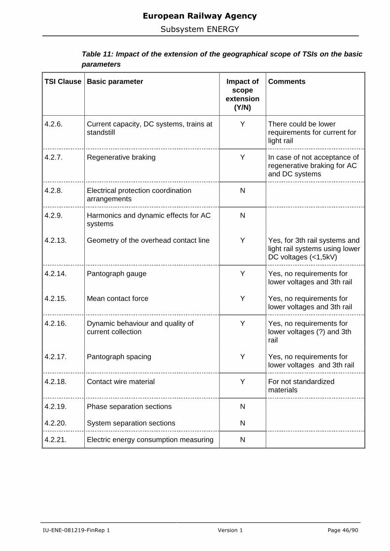
European Railway Agency
Subsystem ENERGY
IU-ENE-081219-FinRep 1 Version 1 Page 46/90
Table 11: Impact of the extension of the geographical scope of TSIs on the basic
parameters
TSI Clause Basic parameter Impact of
scope
extension
(Y/N)
Comments
4.2.6. Current capacity, DC systems, trains at standstill
Y There could be lower requirements for current for light rail
4.2.7. Regenerative braking Y In case of not acceptance of regenerative braking for AC and DC systems
4.2.8. Electrical protection coordination arrangements
N
4.2.9. Harmonics and dynamic effects for AC systems
N
4.2.13. Geometry of the overhead contact line Y Yes, for 3th rail systems and light rail systems using lower DC voltages (<1,5kV)
4.2.14. Pantograph gauge Y Yes, no requirements for lower voltages and 3th rail
4.2.15. Mean contact force Y Yes, no requirements for lower voltages and 3th rail
4.2.16. Dynamic behaviour and quality of current collection
Y Yes, no requirements for lower voltages (?) and 3th rail
4.2.17. Pantograph spacing Y Yes, no requirements for lower voltages and 3th rail
4.2.18. Contact wire material Y For not standardized materials
4.2.19. Phase separation sections N
4.2.20. System separation sections N
4.2.21. Electric energy consumption measuring N
European Railway Agency
Subsystem ENERGY
IU-ENE-081219-FinRep 1 Version 1 Page 47/90
12. List of Annexes
Annex 1 – List of Modifications
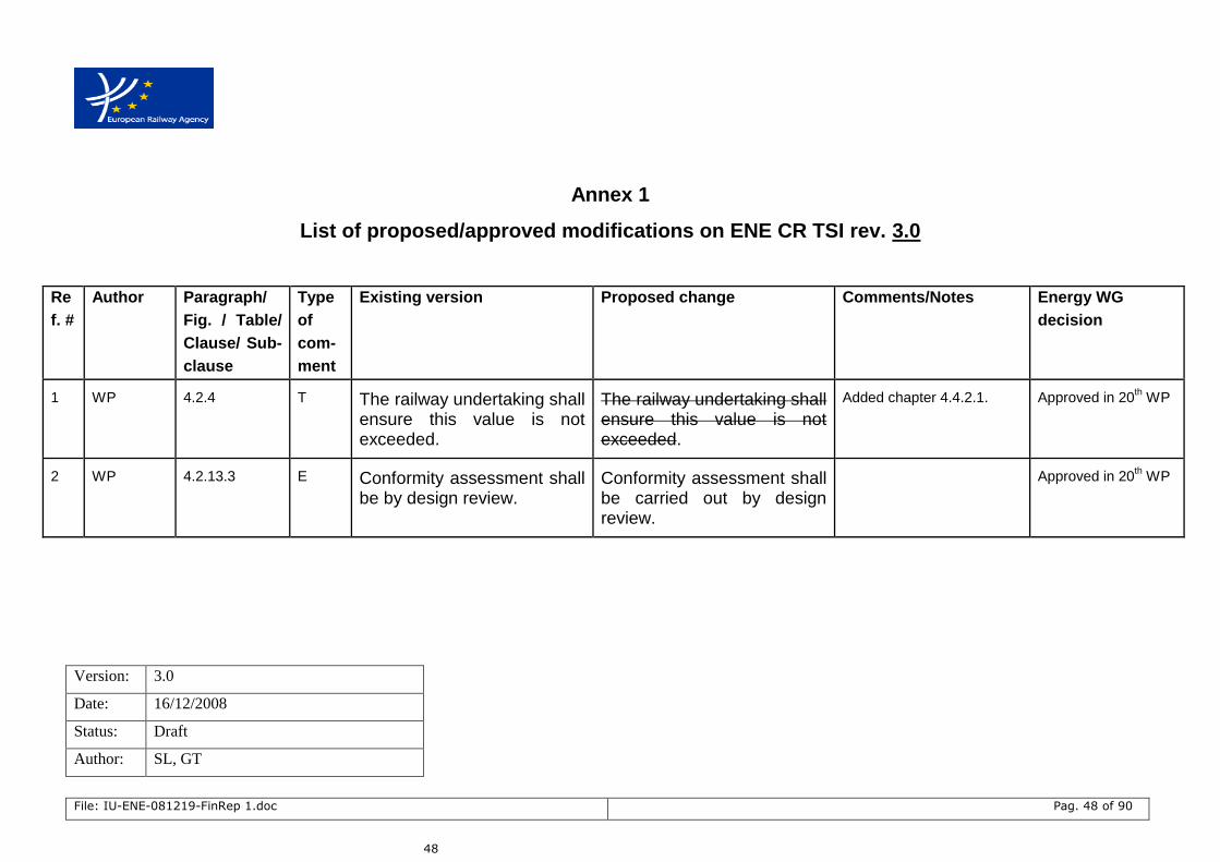
Version: 3.0
Date: 16/12/2008
Status: Draft
Author: SL, GT
File: IU-ENE-081219-FinRep 1.doc Pag. 48 of 90
48
Annex 1
List of proposed/approved modifications on ENE CR TSI rev. 3.0
Re
f. #
Author Paragraph/
Fig. / Table/
Clause/ Sub-
clause
Type
of
com-
ment
Existing version Proposed change Comments/Notes Energy WG
decision
1 WP 4.2.4 T The railway undertaking shall ensure this value is not exceeded.
The railway undertaking shall ensure this value is not exceeded.
Added chapter 4.4.2.1. Approved in 20th WP
2 WP 4.2.13.3 E Conformity assessment shall be by design review.
Conformity assessment shall be carried out by design review.
Approved in 20th WP

European Railway Agency
Subsystem ENERGY
File: IU-ENE-081219-FinRep 1.doc Pag. 49 of 90
Re
f. #
Author Paragraph/
Fig. / Table/
Clause/ Sub-
clause
Type
of
com-
ment
Existing version Proposed change Comments/Notes Energy WG
decision
3 WP 4.2.14 T/E The mechanical kinematic
pantograph gauge for interoperable lines is determined using the method shown in Annex G clause G.2 and the pantograph profiles defined in CR LOC&PAS TSI.
...
Assessment shall be by design review.
The mechanical kinematic pantograph gauge for interoperable lines is determined using the method shown in Annex G clause G.2 and the pantograph profiles defined in CR LOC&PAS TSI.
1950 mm pantograph shall be considered without insulated horns for the gauge calculation.
...
Assessment shall be carried out by design review.
Approved in 20th WP
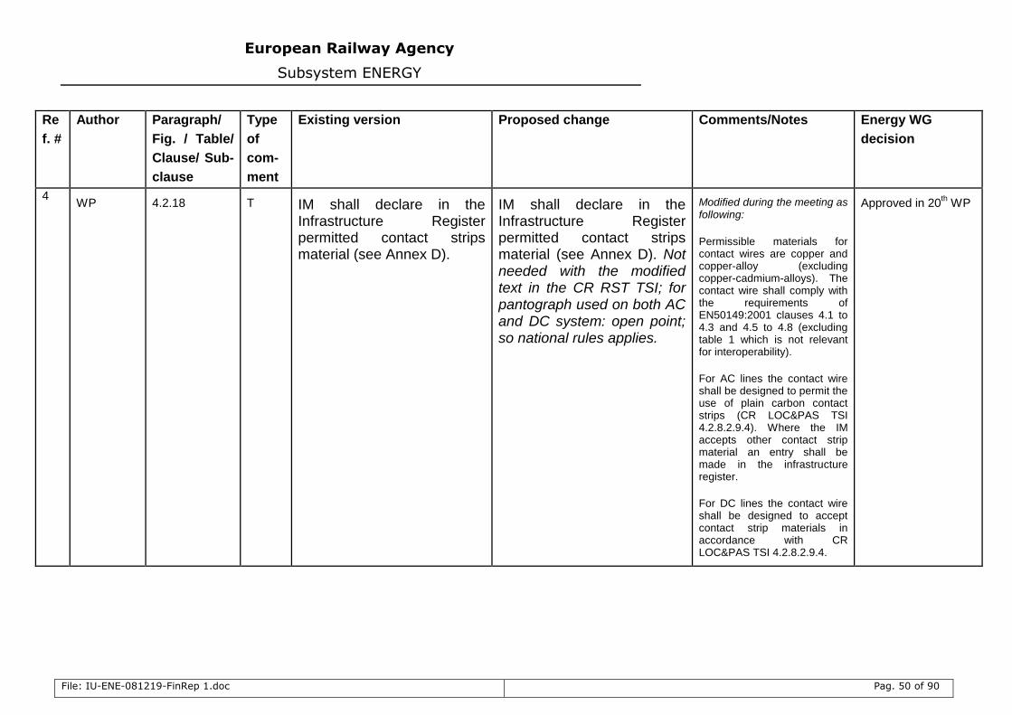
European Railway Agency
Subsystem ENERGY
File: IU-ENE-081219-FinRep 1.doc Pag. 50 of 90
Re
f. #
Author Paragraph/
Fig. / Table/
Clause/ Sub-
clause
Type
of
com-
ment
Existing version Proposed change Comments/Notes Energy WG
decision
4 WP 4.2.18 T IM shall declare in the
Infrastructure Register permitted contact strips material (see Annex D).
IM shall declare in the Infrastructure Register permitted contact strips material (see Annex D). Not needed with the modified text in the CR RST TSI; for pantograph used on both AC and DC system: open point; so national rules applies.
Modified during the meeting as following:
Permissible materials for contact wires are copper and copper-alloy (excluding copper-cadmium-alloys). The contact wire shall comply with the requirements of EN50149:2001 clauses 4.1 to 4.3 and 4.5 to 4.8 (excluding table 1 which is not relevant for interoperability).
For AC lines the contact wire shall be designed to permit the use of plain carbon contact strips (CR LOC&PAS TSI 4.2.8.2.9.4). Where the IM accepts other contact strip material an entry shall be made in the infrastructure register.
For DC lines the contact wire shall be designed to accept contact strip materials in accordance with CR LOC&PAS TSI 4.2.8.2.9.4.
Approved in 20th WP
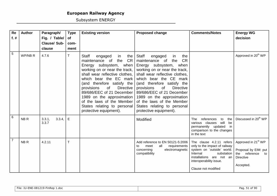
European Railway Agency
Subsystem ENERGY
File: IU-ENE-081219-FinRep 1.doc Pag. 51 of 90
Re
f. #
Author Paragraph/
Fig. / Table/
Clause/ Sub-
clause
Type
of
com-
ment
Existing version Proposed change Comments/Notes Energy WG
decision
5 WP/NB R 4.7.6 T Staff engaged in the
maintenance of the CR Energy subsystem, when working on or near the track, shall wear reflective clothes, which bear the EC mark (and therefore satisfy the provisions of Directive 89/686/EEC of 21 December 1989 on the approximation of the laws of the Member States relating to personal protective equipment).
Staff engaged in the maintenance of the CR Energy subsystem, when working on or near the track, shall wear reflective clothes, which bear the CE mark (and therefore satisfy the provisions of Directive 89/686/EEC of 21 December 1989 on the approximation of the laws of the Member States relating to personal protective equipment).
Approved in 20th WP
6 NB R 3.3.1, 3.3.4,
3.3.7 E Modified The references to the
various clauses will be permanently updated in comparison to the changes in the text
Discussed in 20th WP
7 NB R 4.2.11 T Add reference to EN 50121-5:2006
to meet all requirements concerning electromagnetic compatibility
The clause 4.2.11 refers only to the impact of railway system on `outside` world. Internal substation installations are not an interoperability issue.
Clause not modified
Approved in 21st WP
Proposal by EIM: put the reference to Directive
Accepted.
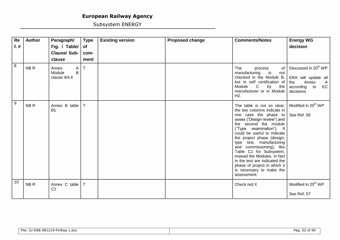
European Railway Agency
Subsystem ENERGY
File: IU-ENE-081219-FinRep 1.doc Pag. 52 of 90
Re
f. #
Author Paragraph/
Fig. / Table/
Clause/ Sub-
clause
Type
of
com-
ment
Existing version Proposed change Comments/Notes Energy WG
decision
8 NB R Annex A
Module B clause 4/4.4
T The process of manufacturing is not checked in the Module B, but in self certification of Module C by the manufacturer or in Module H2.
Discussed in 20th WP
ERA will update all the Annex A according to EC decisions
9 NB R Annex B table
B1 T The table is not so clear;
the two columns indicate in one case the phase to asses (“Design review”) and the second the module (“Type examination”). It could be useful to indicate the project phase (design, type test, manufacturing and commissioning), like Table C1 for Subsystem, instead the Modules. In fact in the text are indicated the phase of project in which it is necessary to make the assessment.
Modified in 20th WP
See Ref. 56
10 NB R Annex C table
C1 T Check red X Modified in 20
th WP
See Ref. 57
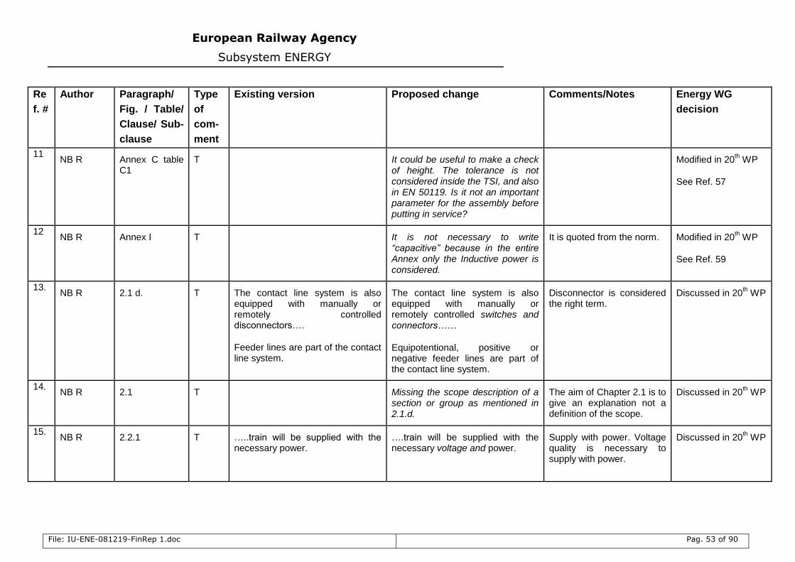
European Railway Agency
Subsystem ENERGY
File: IU-ENE-081219-FinRep 1.doc Pag. 53 of 90
Re
f. #
Author Paragraph/
Fig. / Table/
Clause/ Sub-
clause
Type
of
com-
ment
Existing version Proposed change Comments/Notes Energy WG
decision
11 NB R Annex C table
C1 T It could be useful to make a check
of height. The tolerance is not considered inside the TSI, and also in EN 50119. Is it not an important parameter for the assembly before putting in service?
Modified in 20th WP
See Ref. 57
12 NB R Annex I T It is not necessary to write
“capacitive” because in the entire Annex only the Inductive power is considered.
It is quoted from the norm. Modified in 20th WP
See Ref. 59
13. NB R 2.1 d. T The contact line system is also
equipped with manually or remotely controlled disconnectors….
Feeder lines are part of the contact line system.
The contact line system is also equipped with manually or remotely controlled switches and connectors……
Equipotentional, positive or negative feeder lines are part of the contact line system.
Disconnector is considered the right term.
Discussed in 20th WP
14. NB R 2.1 T Missing the scope description of a
section or group as mentioned in 2.1.d.
The aim of Chapter 2.1 is to give an explanation not a definition of the scope.
Discussed in 20th WP
15. NB R 2.2.1 T …..train will be supplied with the
necessary power.
….train will be supplied with the necessary voltage and power.
Supply with power. Voltage quality is necessary to supply with power.
Discussed in 20th WP
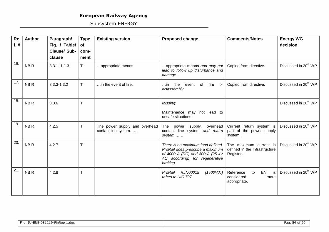
European Railway Agency
Subsystem ENERGY
File: IU-ENE-081219-FinRep 1.doc Pag. 54 of 90
Re
f. #
Author Paragraph/
Fig. / Table/
Clause/ Sub-
clause
Type
of
com-
ment
Existing version Proposed change Comments/Notes Energy WG
decision
16. NB R 3.3.1 -1.1.3 T …appropriate means. …appropriate means and may not
lead to follow up disturbance and damage.
Copied from directive. Discussed in 20th WP
17. NB R 3.3.3-1.3.2 T …in the event of fire. …in the event of fire or
disassembly. Copied from directive. Discussed in 20
th WP
18. NB R 3.3.6 T Missing:
Maintenance may not lead to unsafe situations.
Discussed in 20th WP
19. NB R 4.2.5 T The power supply and overhead
contact line system…… The power supply, overhead contact line system and return system ……
Current return system is part of the power supply system.
Discussed in 20th WP
20. NB R 4.2.7 T There is no maximum load defined.
ProRail does prescribe a maximum of 4000 A (DC) and 800 A (25 kV AC according) for regenerative braking.
The maximum current is defined in the Infrastructure Register.
Discussed in 20th WP
21. NB R 4.2.8 T ProRail RLN00015 (1500Vdc)
refers to UIC 797 Reference to EN is considered more appropriate.
Discussed in 20th WP
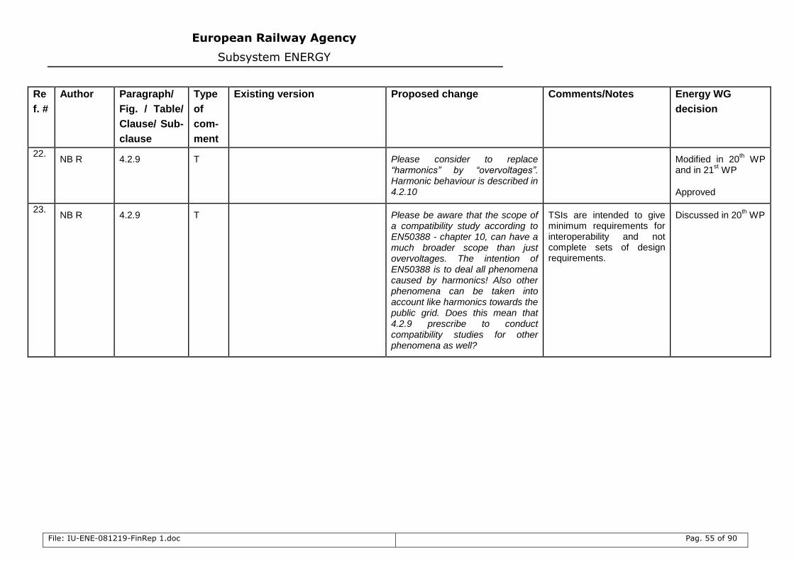
European Railway Agency
Subsystem ENERGY
File: IU-ENE-081219-FinRep 1.doc Pag. 55 of 90
Re
f. #
Author Paragraph/
Fig. / Table/
Clause/ Sub-
clause
Type
of
com-
ment
Existing version Proposed change Comments/Notes Energy WG
decision
22. NB R 4.2.9 T Please consider to replace
“harmonics” by “overvoltages”. Harmonic behaviour is described in 4.2.10
Modified in 20th WP
and in 21st WP
Approved
23. NB R 4.2.9 T Please be aware that the scope of
a compatibility study according to EN50388 - chapter 10, can have a much broader scope than just overvoltages. The intention of EN50388 is to deal all phenomena caused by harmonics! Also other phenomena can be taken into account like harmonics towards the public grid. Does this mean that 4.2.9 prescribe to conduct compatibility studies for other phenomena as well?
TSIs are intended to give minimum requirements for interoperability and not complete sets of design requirements.
Discussed in 20th WP
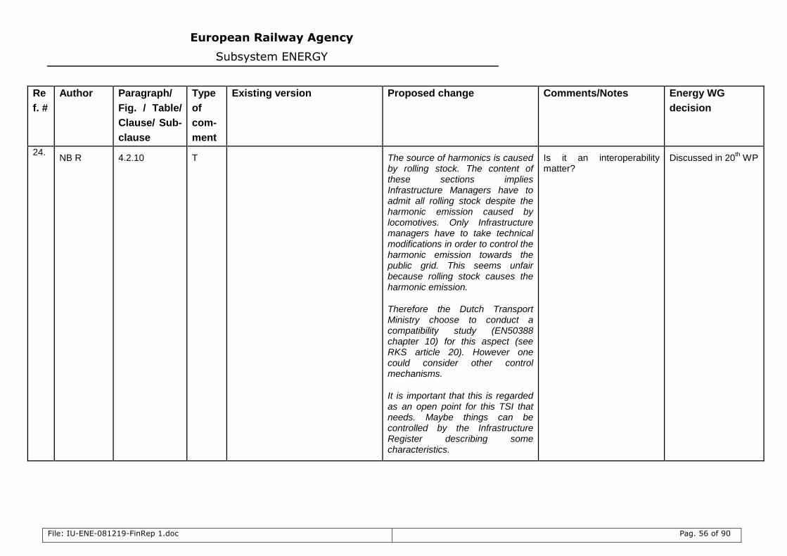
European Railway Agency
Subsystem ENERGY
File: IU-ENE-081219-FinRep 1.doc Pag. 56 of 90
Re
f. #
Author Paragraph/
Fig. / Table/
Clause/ Sub-
clause
Type
of
com-
ment
Existing version Proposed change Comments/Notes Energy WG
decision
24. NB R 4.2.10 T The source of harmonics is caused
by rolling stock. The content of these sections implies Infrastructure Managers have to admit all rolling stock despite the harmonic emission caused by locomotives. Only Infrastructure managers have to take technical modifications in order to control the harmonic emission towards the public grid. This seems unfair because rolling stock causes the harmonic emission.
Therefore the Dutch Transport Ministry choose to conduct a compatibility study (EN50388 chapter 10) for this aspect (see RKS article 20). However one could consider other control mechanisms.
It is important that this is regarded as an open point for this TSI that needs. Maybe things can be controlled by the Infrastructure Register describing some characteristics.
Is it an interoperability matter?
Discussed in 20th WP
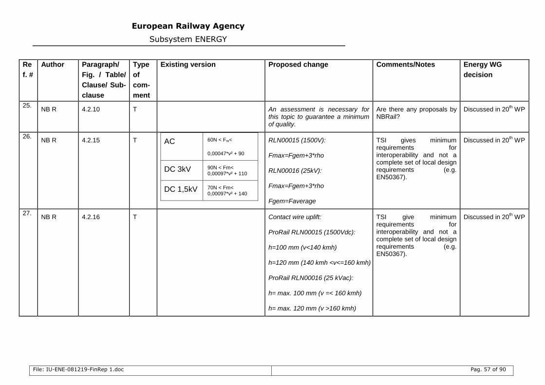
European Railway Agency
Subsystem ENERGY
File: IU-ENE-081219-FinRep 1.doc Pag. 57 of 90
Re
f. #
Author Paragraph/
Fig. / Table/
Clause/ Sub-
clause
Type
of
com-
ment
Existing version Proposed change Comments/Notes Energy WG
decision
25. NB R 4.2.10 T An assessment is necessary for
this topic to guarantee a minimum of quality.
Are there any proposals by NBRail?
Discussed in 20th WP
26. NB R 4.2.15 T AC 60N < Fm<
0,00047*v² + 90
DC 3kV 90N < Fm< 0,00097*v² + 110
DC 1,5kV 70N < Fm< 0,00097*v² + 140
RLN00015 (1500V):
Fmax=Fgem+3*rho
RLN00016 (25kV):
Fmax=Fgem+3*rho
Fgem=Faverage
TSI gives minimum requirements for interoperability and not a complete set of local design requirements (e.g. EN50367).
Discussed in 20th WP
27. NB R 4.2.16 T Contact wire uplift:
ProRail RLN00015 (1500Vdc):
h=100 mm (v<140 kmh)
h=120 mm (140 kmh <v<=160 kmh)
ProRail RLN00016 (25 kVac):
h= max. 100 mm (v =< 160 kmh)
h= max. 120 mm (v >160 kmh)
TSI give minimum requirements for interoperability and not a complete set of local design requirements (e.g. EN50367).
Discussed in 20th WP
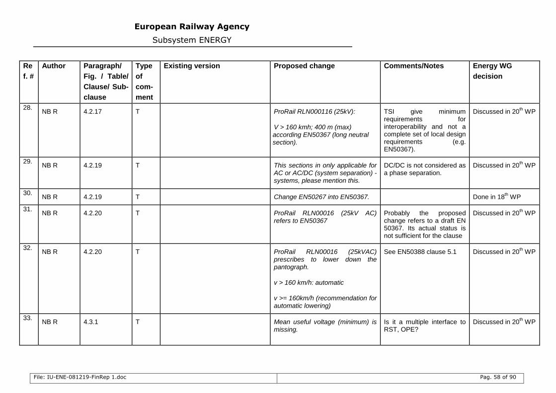
European Railway Agency
Subsystem ENERGY
File: IU-ENE-081219-FinRep 1.doc Pag. 58 of 90
Re
f. #
Author Paragraph/
Fig. / Table/
Clause/ Sub-
clause
Type
of
com-
ment
Existing version Proposed change Comments/Notes Energy WG
decision
28. NB R 4.2.17 T ProRail RLN000116 (25kV):
V > 160 kmh; 400 m (max) according EN50367 (long neutral section).
TSI give minimum requirements for interoperability and not a complete set of local design requirements (e.g. EN50367).
Discussed in 20th WP
29. NB R 4.2.19 T This sections in only applicable for
AC or AC/DC (system separation) -systems, please mention this.
DC/DC is not considered as a phase separation.
Discussed in 20th WP
30. NB R 4.2.19 T Change EN50267 into EN50367. Done in 18
th WP
31. NB R 4.2.20 T ProRail RLN00016 (25kV AC)
refers to EN50367 Probably the proposed change refers to a draft EN 50367. Its actual status is not sufficient for the clause
Discussed in 20th WP
32. NB R 4.2.20 T ProRail RLN00016 (25kVAC)
prescribes to lower down the pantograph.
v > 160 km/h: automatic
v >= 160km/h (recommendation for automatic lowering)
See EN50388 clause 5.1 Discussed in 20th WP
33. NB R 4.3.1 T Mean useful voltage (minimum) is
missing. Is it a multiple interface to RST, OPE?
Discussed in 20th WP
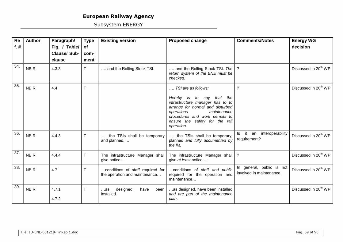
European Railway Agency
Subsystem ENERGY
File: IU-ENE-081219-FinRep 1.doc Pag. 59 of 90
Re
f. #
Author Paragraph/
Fig. / Table/
Clause/ Sub-
clause
Type
of
com-
ment
Existing version Proposed change Comments/Notes Energy WG
decision
34. NB R 4.3.3 T …. and the Rolling Stock TSI. …. and the Rolling Stock TSI. The
return system of the ENE must be checked.
? Discussed in 20th WP
35. NB R 4.4 T …. TSI are as follows:
Hereby is to say that the infrastructure manager has to to arrange for normal and disturbed operations maintenance procedures and work permits to ensure the safety for the rail operation.
? Discussed in 20th WP
36. NB R 4.4.3 T ……the TSIs shall be temporary
and planned, ... ……the TSIs shall be temporary, planned and fully documented by the IM,
Is it an interoperability
requirement? Discussed in 20
th WP
37. NB R 4.4.4 T The infrastructure Manager shall
give notice…. The infrastructure Manager shall give at least notice….
? Discussed in 20th WP
38. NB R 4.7 T …conditions of staff required for
the operation and maintenance… …conditions of staff and public required for the operation and maintenance…
In general, public is not
involved in maintenance. Discussed in 20
th WP
39. NB R 4.7.1
4.7.2
T …as designed, have been installed.
…as designed, have been installed and are part of the maintenance plan.
Discussed in 20th WP
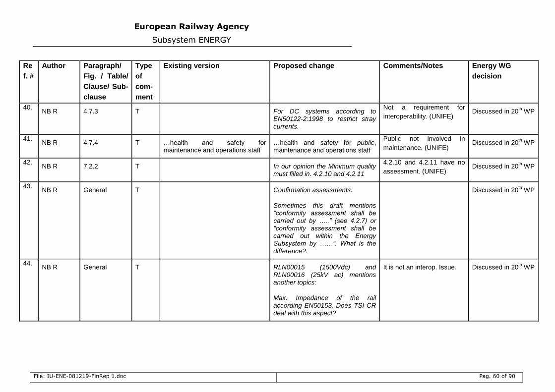
European Railway Agency
Subsystem ENERGY
File: IU-ENE-081219-FinRep 1.doc Pag. 60 of 90
Re
f. #
Author Paragraph/
Fig. / Table/
Clause/ Sub-
clause
Type
of
com-
ment
Existing version Proposed change Comments/Notes Energy WG
decision
40. NB R 4.7.3 T For DC systems according to
EN50122-2:1998 to restrict stray currents.
Not a requirement for
interoperability. (UNIFE) Discussed in 20
th WP
41. NB R 4.7.4 T …health and safety for
maintenance and operations staff …health and safety for public, maintenance and operations staff
Public not involved in
maintenance. (UNIFE) Discussed in 20
th WP
42. NB R 7.2.2 T In our opinion the Minimum quality
must filled in. 4.2.10 and 4.2.11
4.2.10 and 4.2.11 have no
assessment. (UNIFE) Discussed in 20
th WP
43. NB R General T Confirmation assessments:
Sometimes this draft mentions “conformity assessment shall be carried out by …..” (see 4.2.7) or “conformity assessment shall be carried out within the Energy Subsystem by ……”. What is the difference?.
Discussed in 20th WP
44. NB R General T RLN00015 (1500Vdc) and
RLN00016 (25kV ac) mentions another topics:
Max. Impedance of the rail according EN50153. Does TSI CR deal with this aspect?
It is not an interop. Issue. Discussed in 20th WP
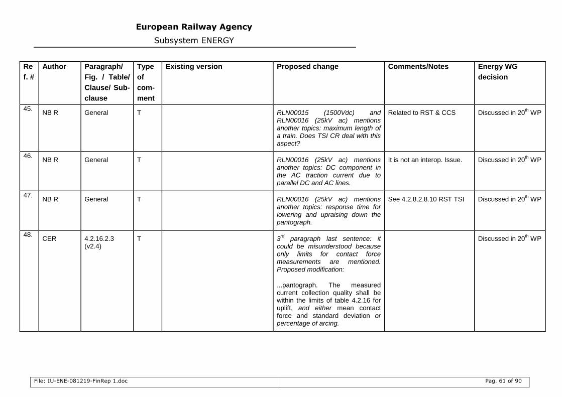
European Railway Agency
Subsystem ENERGY
File: IU-ENE-081219-FinRep 1.doc Pag. 61 of 90
Re
f. #
Author Paragraph/
Fig. / Table/
Clause/ Sub-
clause
Type
of
com-
ment
Existing version Proposed change Comments/Notes Energy WG
decision
45. NB R General T RLN00015 (1500Vdc) and
RLN00016 (25kV ac) mentions another topics: maximum length of a train. Does TSI CR deal with this aspect?
Related to RST & CCS Discussed in 20th WP
46. NB R General T RLN00016 (25kV ac) mentions
another topics: DC component in the AC traction current due to parallel DC and AC lines.
It is not an interop. Issue. Discussed in 20th WP
47. NB R General T RLN00016 (25kV ac) mentions
another topics: response time for lowering and upraising down the pantograph.
See 4.2.8.2.8.10 RST TSI Discussed in 20th WP
48. CER 4.2.16.2.3
(v2.4) T 3
rd paragraph last sentence: it
could be misunderstood because only limits for contact force measurements are mentioned. Proposed modification:
...pantograph. The measured current collection quality shall be within the limits of table 4.2.16 for uplift, and either mean contact force and standard deviation or percentage of arcing.
Discussed in 20th WP
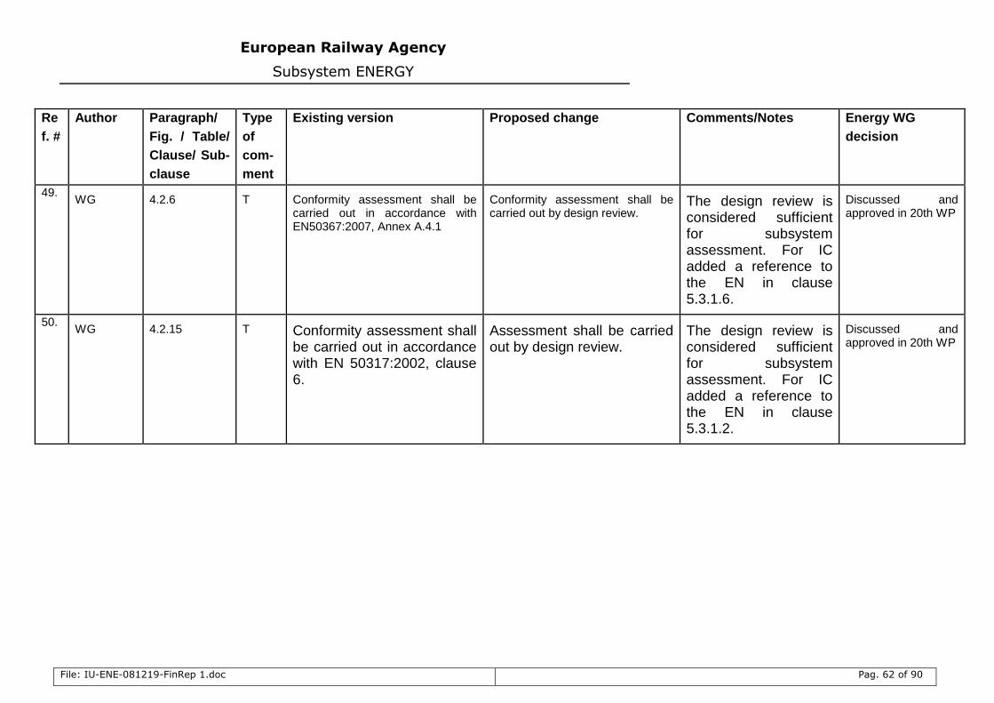
European Railway Agency
Subsystem ENERGY
File: IU-ENE-081219-FinRep 1.doc Pag. 62 of 90
Re
f. #
Author Paragraph/
Fig. / Table/
Clause/ Sub-
clause
Type
of
com-
ment
Existing version Proposed change Comments/Notes Energy WG
decision
49. WG 4.2.6 T Conformity assessment shall be
carried out in accordance with EN50367:2007, Annex A.4.1
Conformity assessment shall be carried out by design review.
The design review is considered sufficient for subsystem assessment. For IC added a reference to the EN in clause 5.3.1.6.
Discussed and approved in 20th WP
50. WG 4.2.15 T Conformity assessment shall
be carried out in accordance with EN 50317:2002, clause 6.
Assessment shall be carried out by design review.
The design review is considered sufficient for subsystem assessment. For IC added a reference to the EN in clause 5.3.1.2.
Discussed and approved in 20th WP
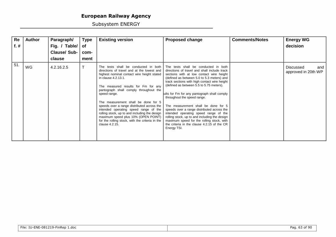
European Railway Agency
Subsystem ENERGY
File: IU-ENE-081219-FinRep 1.doc Pag. 63 of 90
Re
f. #
Author Paragraph/
Fig. / Table/
Clause/ Sub-
clause
Type
of
com-
ment
Existing version Proposed change Comments/Notes Energy WG
decision
51. WG 4.2.16.2.5 T The tests shall be conducted in both
directions of travel and at the lowest and highest nominal contact wire height stated in clause 4.2.13.1.
The measured results for Fm for any pantograph shall comply throughout the speed range.
The measurement shall be done for 5 speeds over a range distributed across the intended operating speed range of the rolling stock, up to and including the design maximum speed plus 10% (OPEN POINT) for the rolling stock, with the criteria in the clause 4.2.15.
The tests shall be conducted in both directions of travel and shall include track sections with at low contact wire height (defined as between 5.0 to 5.3 meters) and track sections with high contact wire height (defined as between 5.5 to 5.75 meters).
The measured results for Fm for any pantograph shall comply throughout the speed range.
The measurement shall be done for 5 speeds over a range distributed across the intended operating speed range of the rolling stock, up to and including the design maximum speed for the rolling stock, with the criteria in the clause 4.2.15 of the CR Energy TSI.
Discussed and approved in 20th WP
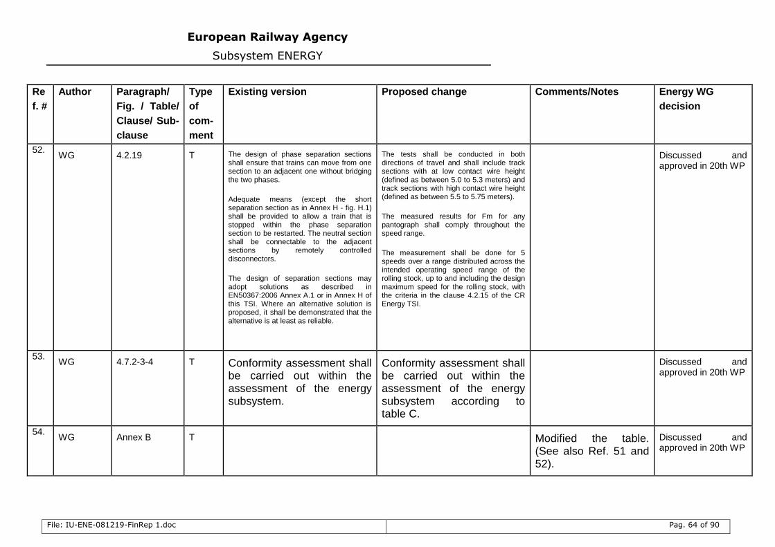
European Railway Agency
Subsystem ENERGY
File: IU-ENE-081219-FinRep 1.doc Pag. 64 of 90
Re
f. #
Author Paragraph/
Fig. / Table/
Clause/ Sub-
clause
Type
of
com-
ment
Existing version Proposed change Comments/Notes Energy WG
decision
52. WG 4.2.19 T The design of phase separation sections
shall ensure that trains can move from one section to an adjacent one without bridging the two phases.
Adequate means (except the short separation section as in Annex H - fig. H.1) shall be provided to allow a train that is stopped within the phase separation section to be restarted. The neutral section shall be connectable to the adjacent sections by remotely controlled disconnectors.
The design of separation sections may adopt solutions as described in EN50367:2006 Annex A.1 or in Annex H of this TSI. Where an alternative solution is proposed, it shall be demonstrated that the alternative is at least as reliable.
The tests shall be conducted in both directions of travel and shall include track sections with at low contact wire height (defined as between 5.0 to 5.3 meters) and track sections with high contact wire height (defined as between 5.5 to 5.75 meters).
The measured results for Fm for any pantograph shall comply throughout the speed range.
The measurement shall be done for 5 speeds over a range distributed across the intended operating speed range of the rolling stock, up to and including the design maximum speed for the rolling stock, with the criteria in the clause 4.2.15 of the CR Energy TSI.
Discussed and approved in 20th WP
53. WG 4.7.2-3-4 T Conformity assessment shall
be carried out within the assessment of the energy subsystem.
Conformity assessment shall be carried out within the assessment of the energy subsystem according to table C.
Discussed and approved in 20th WP
54. WG Annex B T Modified the table.
(See also Ref. 51 and 52).
Discussed and approved in 20th WP
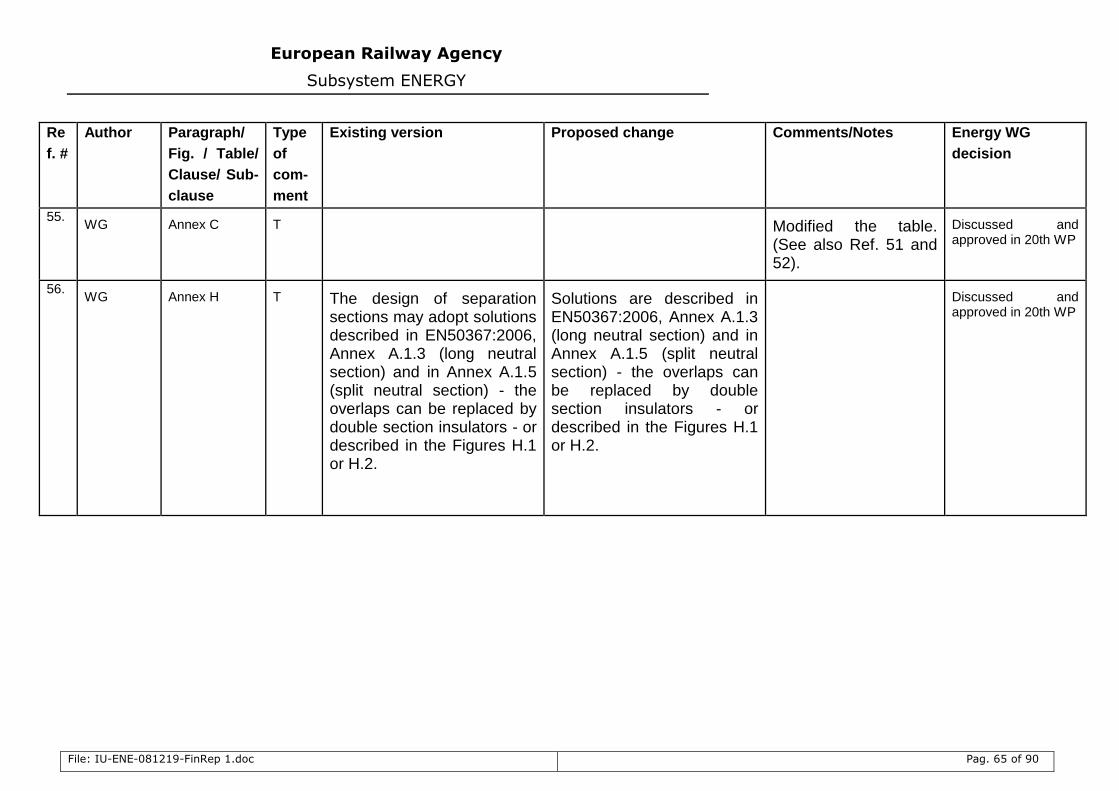
European Railway Agency
Subsystem ENERGY
File: IU-ENE-081219-FinRep 1.doc Pag. 65 of 90
Re
f. #
Author Paragraph/
Fig. / Table/
Clause/ Sub-
clause
Type
of
com-
ment
Existing version Proposed change Comments/Notes Energy WG
decision
55. WG Annex C T Modified the table.
(See also Ref. 51 and 52).
Discussed and approved in 20th WP
56. WG Annex H T The design of separation
sections may adopt solutions described in EN50367:2006, Annex A.1.3 (long neutral section) and in Annex A.1.5 (split neutral section) - the overlaps can be replaced by double section insulators - or described in the Figures H.1 or H.2.
Solutions are described in EN50367:2006, Annex A.1.3 (long neutral section) and in Annex A.1.5 (split neutral section) - the overlaps can be replaced by double section insulators - or described in the Figures H.1 or H.2.
Discussed and approved in 20th WP
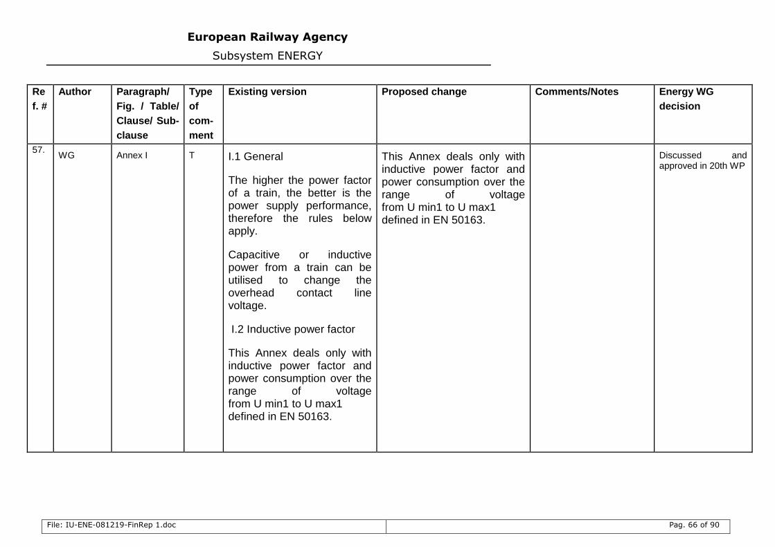
European Railway Agency
Subsystem ENERGY
File: IU-ENE-081219-FinRep 1.doc Pag. 66 of 90
Re
f. #
Author Paragraph/
Fig. / Table/
Clause/ Sub-
clause
Type
of
com-
ment
Existing version Proposed change Comments/Notes Energy WG
decision
57. WG Annex I T I.1 General
The higher the power factor of a train, the better is the power supply performance, therefore the rules below apply.
Capacitive or inductive power from a train can be utilised to change the overhead contact line voltage.
I.2 Inductive power factor
This Annex deals only with inductive power factor and power consumption over the range of voltage from U min1 to U max1 defined in EN 50163.
This Annex deals only with inductive power factor and power consumption over the range of voltage from U min1 to U max1 defined in EN 50163.
Discussed and approved in 20th WP
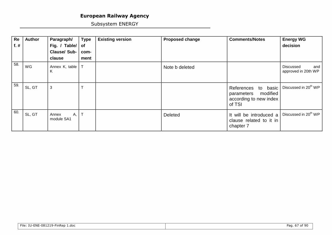
European Railway Agency
Subsystem ENERGY
File: IU-ENE-081219-FinRep 1.doc Pag. 67 of 90
Re
f. #
Author Paragraph/
Fig. / Table/
Clause/ Sub-
clause
Type
of
com-
ment
Existing version Proposed change Comments/Notes Energy WG
decision
58. WG Annex K, table
K T Note b deleted
Discussed and approved in 20th WP
59. SL, GT 3 T References to basic
parameters modified according to new index of TSI
Discussed in 20th WP
60. SL, GT Annex A,
module SA1 T Deleted
It will be introduced a clause related to it in chapter 7
Discussed in 20th WP
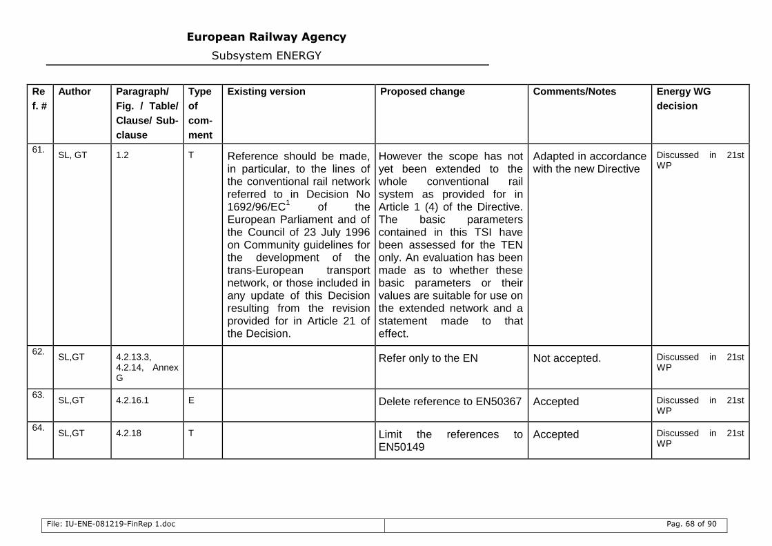
European Railway Agency
Subsystem ENERGY
File: IU-ENE-081219-FinRep 1.doc Pag. 68 of 90
Re
f. #
Author Paragraph/
Fig. / Table/
Clause/ Sub-
clause
Type
of
com-
ment
Existing version Proposed change Comments/Notes Energy WG
decision
61. SL, GT 1.2 T Reference should be made,
in particular, to the lines of the conventional rail network referred to in Decision No 1692/96/EC
1 of the
European Parliament and of the Council of 23 July 1996 on Community guidelines for the development of the trans-European transport network, or those included in any update of this Decision resulting from the revision provided for in Article 21 of the Decision.
However the scope has not yet been extended to the whole conventional rail system as provided for in Article 1 (4) of the Directive. The basic parameters contained in this TSI have been assessed for the TEN only. An evaluation has been made as to whether these basic parameters or their values are suitable for use on the extended network and a statement made to that effect.
Adapted in accordance with the new Directive
Discussed in 21st WP
62. SL,GT 4.2.13.3,
4.2.14, Annex G
Refer only to the EN Not accepted. Discussed in 21st WP
63. SL,GT 4.2.16.1 E Delete reference to EN50367 Accepted Discussed in 21st
WP
64. SL,GT 4.2.18 T Limit the references to
EN50149 Accepted Discussed in 21st
WP
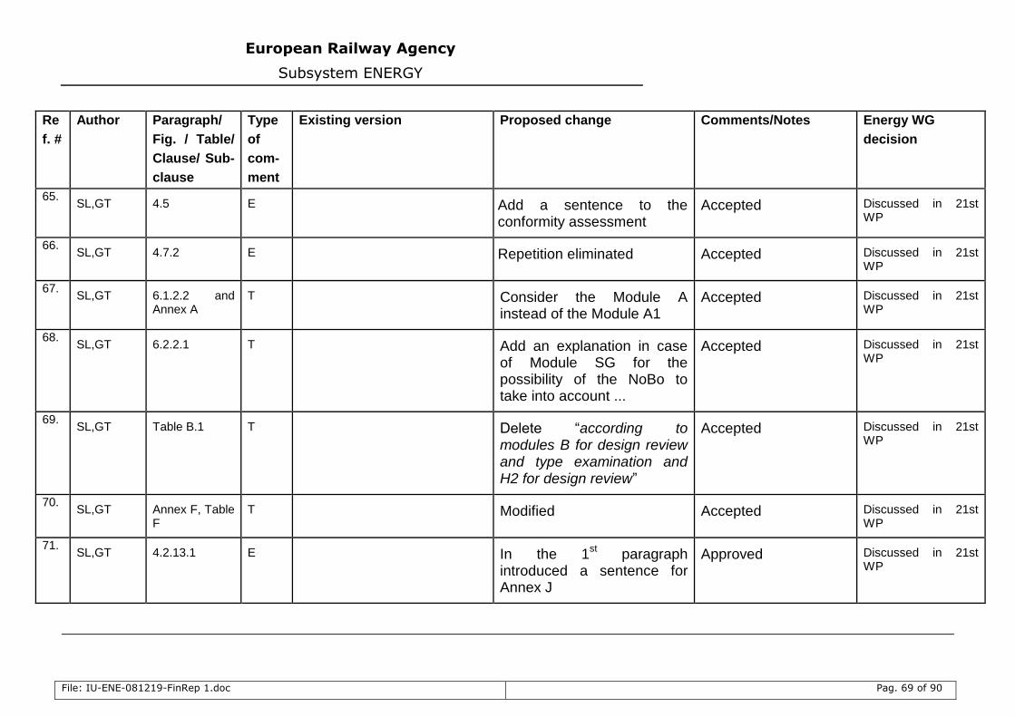
European Railway Agency
Subsystem ENERGY
File: IU-ENE-081219-FinRep 1.doc Pag. 69 of 90
Re
f. #
Author Paragraph/
Fig. / Table/
Clause/ Sub-
clause
Type
of
com-
ment
Existing version Proposed change Comments/Notes Energy WG
decision
65. SL,GT 4.5 E Add a sentence to the
conformity assessment Accepted Discussed in 21st
WP
66. SL,GT 4.7.2 E Repetition eliminated Accepted Discussed in 21st
WP
67. SL,GT 6.1.2.2 and
Annex A T Consider the Module A
instead of the Module A1 Accepted Discussed in 21st
WP
68. SL,GT 6.2.2.1 T Add an explanation in case
of Module SG for the possibility of the NoBo to take into account ...
Accepted Discussed in 21st WP
69. SL,GT Table B.1 T Delete “according to
modules B for design review and type examination and H2 for design review”
Accepted Discussed in 21st WP
70. SL,GT Annex F, Table
F T Modified Accepted Discussed in 21st
WP
71. SL,GT 4.2.13.1 E In the 1
st paragraph
introduced a sentence for Annex J
Approved Discussed in 21st WP
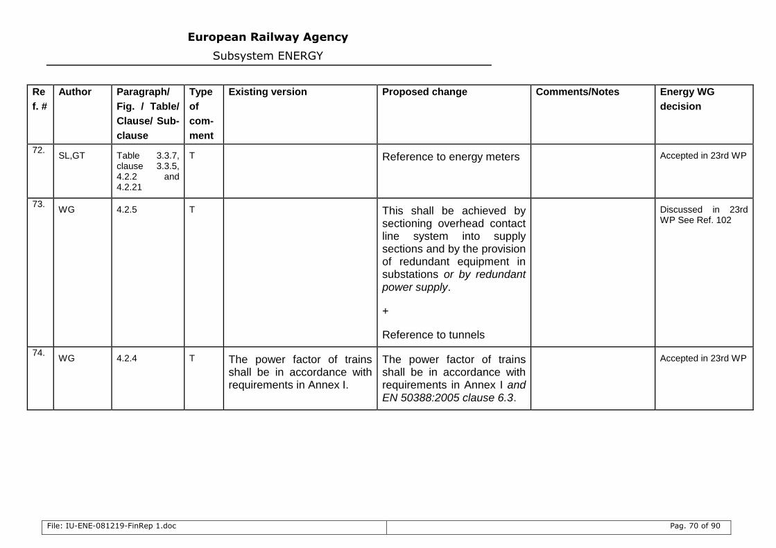
European Railway Agency
Subsystem ENERGY
File: IU-ENE-081219-FinRep 1.doc Pag. 70 of 90
Re
f. #
Author Paragraph/
Fig. / Table/
Clause/ Sub-
clause
Type
of
com-
ment
Existing version Proposed change Comments/Notes Energy WG
decision
72. SL,GT Table 3.3.7,
clause 3.3.5, 4.2.2 and 4.2.21
T Reference to energy meters Accepted in 23rd WP
73. WG 4.2.5 T This shall be achieved by
sectioning overhead contact line system into supply sections and by the provision of redundant equipment in substations or by redundant power supply.
+
Reference to tunnels
Discussed in 23rd WP See Ref. 102
74. WG 4.2.4 T The power factor of trains
shall be in accordance with requirements in Annex I.
The power factor of trains shall be in accordance with requirements in Annex I and EN 50388:2005 clause 6.3.
Accepted in 23rd WP
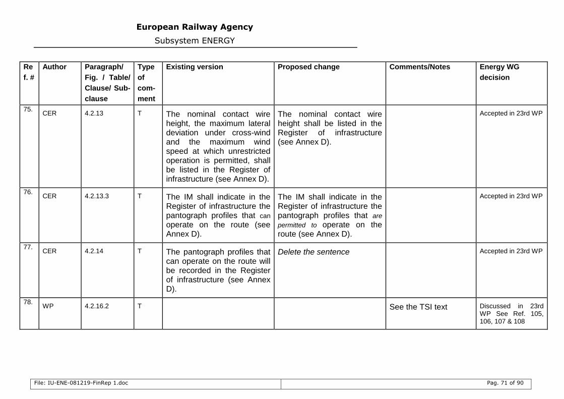
European Railway Agency
Subsystem ENERGY
File: IU-ENE-081219-FinRep 1.doc Pag. 71 of 90
Re
f. #
Author Paragraph/
Fig. / Table/
Clause/ Sub-
clause
Type
of
com-
ment
Existing version Proposed change Comments/Notes Energy WG
decision
75. CER 4.2.13 T The nominal contact wire
height, the maximum lateral deviation under cross-wind and the maximum wind speed at which unrestricted operation is permitted, shall be listed in the Register of infrastructure (see Annex D).
The nominal contact wire height shall be listed in the Register of infrastructure (see Annex D).
Accepted in 23rd WP
76. CER 4.2.13.3 T The IM shall indicate in the
Register of infrastructure the pantograph profiles that can
operate on the route (see Annex D).
The IM shall indicate in the Register of infrastructure the pantograph profiles that are
permitted to operate on the route (see Annex D).
Accepted in 23rd WP
77. CER 4.2.14 T The pantograph profiles that
can operate on the route will be recorded in the Register of infrastructure (see Annex D).
Delete the sentence Accepted in 23rd WP
78. WP 4.2.16.2 T See the TSI text Discussed in 23rd
WP See Ref. 105, 106, 107 & 108
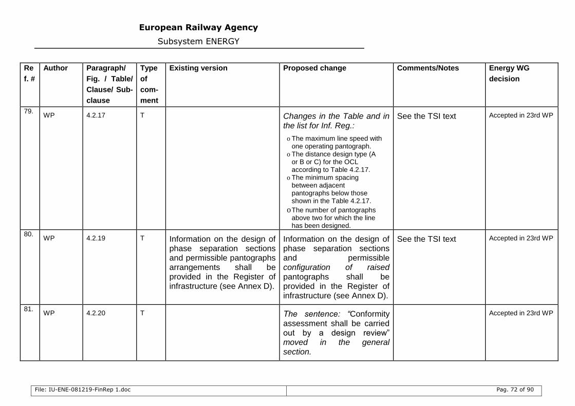
European Railway Agency
Subsystem ENERGY
File: IU-ENE-081219-FinRep 1.doc Pag. 72 of 90
Re
f. #
Author Paragraph/
Fig. / Table/
Clause/ Sub-
clause
Type
of
com-
ment
Existing version Proposed change Comments/Notes Energy WG
decision
79. WP 4.2.17 T Changes in the Table and in
the list for Inf. Reg.:
o The maximum line speed with one operating pantograph.
o The distance design type (A or B or C) for the OCL according to Table 4.2.17.
o The minimum spacing between adjacent pantographs below those shown in the Table 4.2.17.
o The number of pantographs above two for which the line has been designed.
See the TSI text Accepted in 23rd WP
80. WP 4.2.19 T Information on the design of
phase separation sections and permissible pantographs arrangements shall be provided in the Register of infrastructure (see Annex D).
Information on the design of phase separation sections and permissible configuration of raised pantographs shall be provided in the Register of infrastructure (see Annex D).
See the TSI text Accepted in 23rd WP
81. WP 4.2.20 T The sentence: “Conformity
assessment shall be carried out by a design review” moved in the general section.
Accepted in 23rd WP
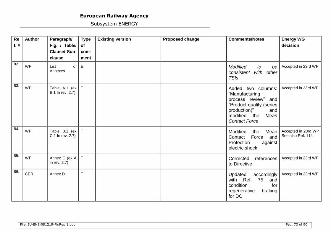
European Railway Agency
Subsystem ENERGY
File: IU-ENE-081219-FinRep 1.doc Pag. 73 of 90
Re
f. #
Author Paragraph/
Fig. / Table/
Clause/ Sub-
clause
Type
of
com-
ment
Existing version Proposed change Comments/Notes Energy WG
decision
82. WP List of
Annexes E Modified to be
consistent with other TSIs
Accepted in 23rd WP
83. WP Table A.1 (ex
B.1 In rev. 2.7) T Added two columns:
“Manufacturing process review” and “Product quality (series production)” and modified the Mean Contact Force
Accepted in 23rd WP
84. WP Table B.1 (ex
C.1 In rev. 2.7) T Modified the Mean
Contact Force and Protection against electric shock
Accepted in 23rd WP See also Ref. 114
85. WP Annex C (ex A
in rev. 2.7) T Corrected references
to Directive
Accepted in 23rd WP
86. CER Annex D T Updated accordingly
with Ref. 75 and condition for regenerative braking for DC
Accepted in 23rd WP
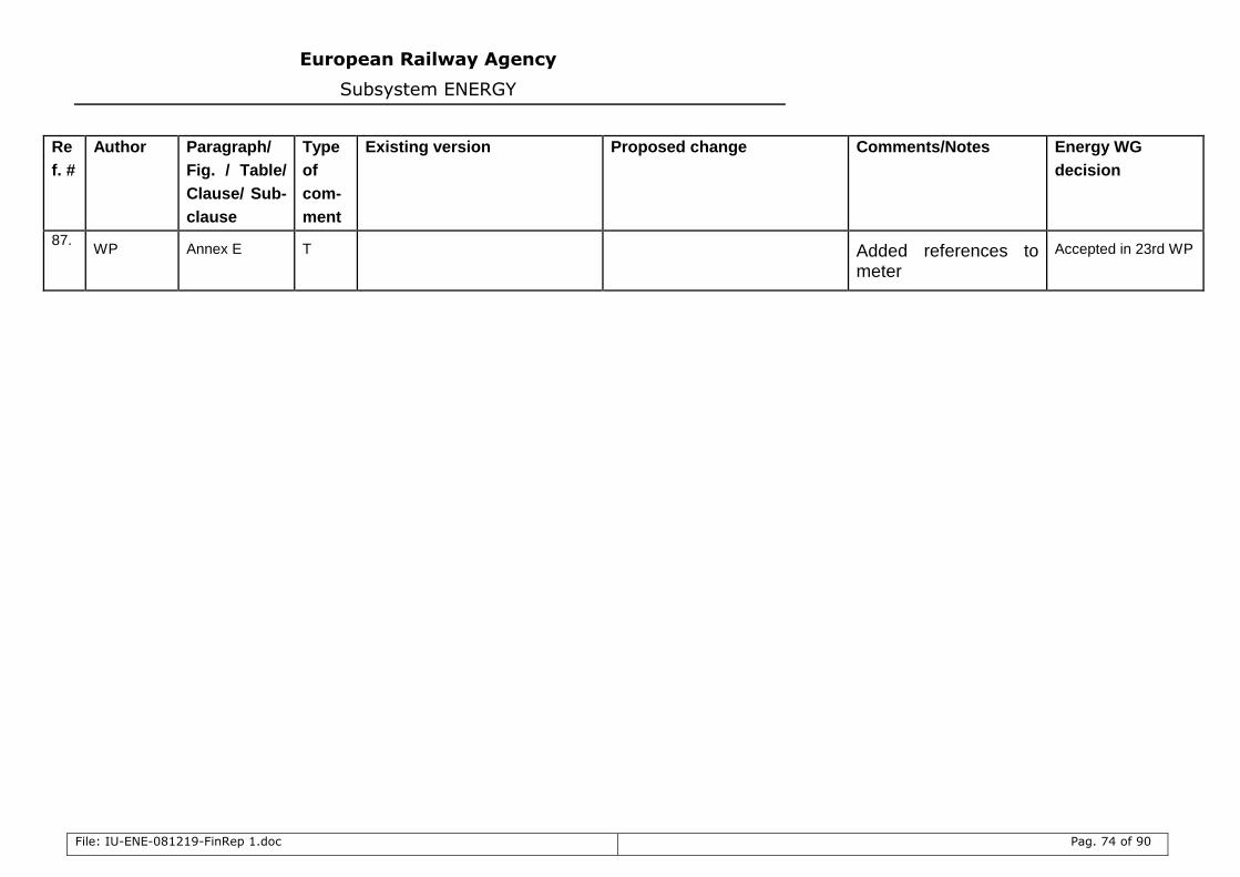
European Railway Agency
Subsystem ENERGY
File: IU-ENE-081219-FinRep 1.doc Pag. 74 of 90
Re
f. #
Author Paragraph/
Fig. / Table/
Clause/ Sub-
clause
Type
of
com-
ment
Existing version Proposed change Comments/Notes Energy WG
decision
87. WP Annex E T Added references to
meter
Accepted in 23rd WP
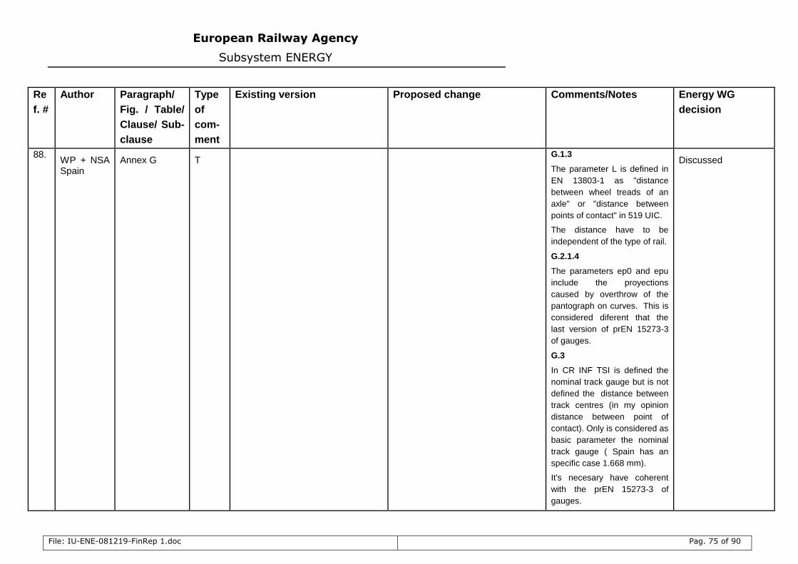
European Railway Agency
Subsystem ENERGY
File: IU-ENE-081219-FinRep 1.doc Pag. 75 of 90
Re
f. #
Author Paragraph/
Fig. / Table/
Clause/ Sub-
clause
Type
of
com-
ment
Existing version Proposed change Comments/Notes Energy WG
decision
88. WP + NSA Spain
Annex G T G.1.3
The parameter L is defined in
EN 13803-1 as "distance
between wheel treads of an
axle" or "distance between
points of contact" in 519 UIC.
The distance have to be
independent of the type of rail.
G.2.1.4
The parameters ep0 and epu
include the proyections
caused by overthrow of the
pantograph on curves. This is
considered diferent that the
last version of prEN 15273-3
of gauges.
G.3
In CR INF TSI is defined the
nominal track gauge but is not
defined the distance between
track centres (in my opinion
distance between point of
contact). Only is considered as
basic parameter the nominal
track gauge ( Spain has an
specific case 1.668 mm).
It's necesary have coherent
with the prEN 15273-3 of
gauges.
Discussed
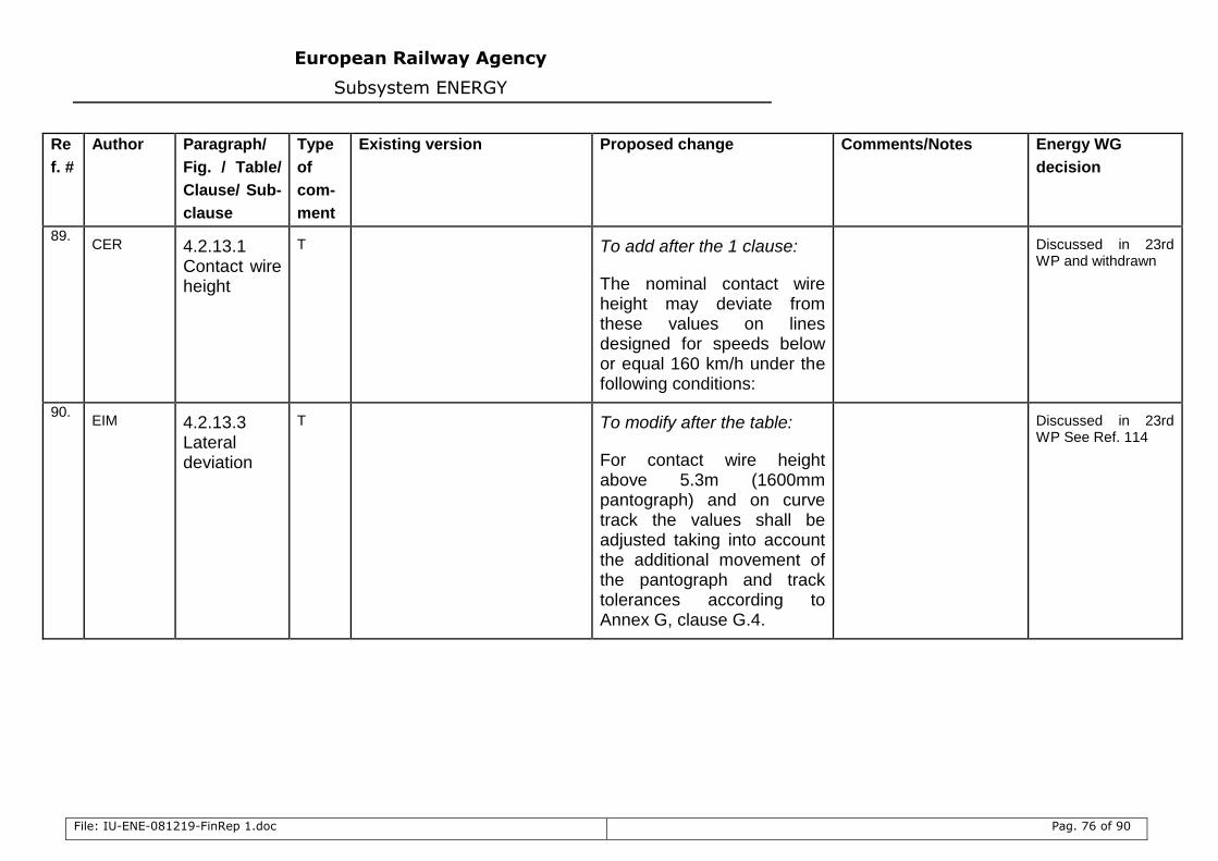
European Railway Agency
Subsystem ENERGY
File: IU-ENE-081219-FinRep 1.doc Pag. 76 of 90
Re
f. #
Author Paragraph/
Fig. / Table/
Clause/ Sub-
clause
Type
of
com-
ment
Existing version Proposed change Comments/Notes Energy WG
decision
89. CER 4.2.13.1
Contact wire height
T To add after the 1 clause:
The nominal contact wire height may deviate from these values on lines designed for speeds below or equal 160 km/h under the following conditions:
Discussed in 23rd WP and withdrawn
90. EIM 4.2.13.3
Lateral deviation
T To modify after the table:
For contact wire height above 5.3m (1600mm pantograph) and on curve track the values shall be adjusted taking into account the additional movement of the pantograph and track tolerances according to Annex G, clause G.4.
Discussed in 23rd WP See Ref. 114
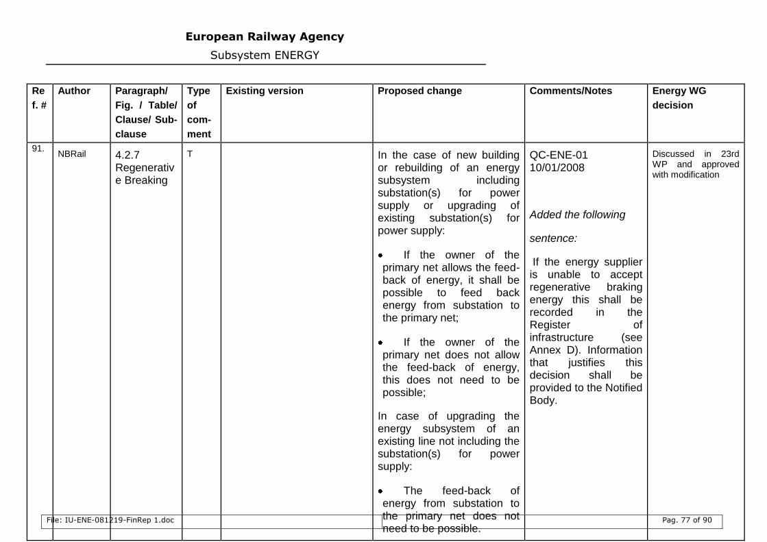
European Railway Agency
Subsystem ENERGY
File: IU-ENE-081219-FinRep 1.doc Pag. 77 of 90
Re
f. #
Author Paragraph/
Fig. / Table/
Clause/ Sub-
clause
Type
of
com-
ment
Existing version Proposed change Comments/Notes Energy WG
decision
91. NBRail 4.2.7
Regenerative Breaking
T In the case of new building or rebuilding of an energy subsystem including substation(s) for power supply or upgrading of existing substation(s) for power supply:
If the owner of the primary net allows the feed-back of energy, it shall be possible to feed back energy from substation to the primary net;
If the owner of the primary net does not allow the feed-back of energy, this does not need to be possible;
In case of upgrading the energy subsystem of an existing line not including the substation(s) for power supply:
The feed-back of energy from substation to the primary net does not need to be possible.
QC-ENE-01 10/01/2008
Added the following
sentence:
If the energy supplier is unable to accept regenerative braking energy this shall be recorded in the Register of infrastructure (see Annex D). Information that justifies this decision shall be provided to the Notified Body.
Discussed in 23rd WP and approved with modification

European Railway Agency
Subsystem ENERGY
File: IU-ENE-081219-FinRep 1.doc Pag. 78 of 90
Re
f. #
Author Paragraph/
Fig. / Table/
Clause/ Sub-
clause
Type
of
com-
ment
Existing version Proposed change Comments/Notes Energy WG
decision
92. NSA Spain 5 IC T
In Spain like in other countries it
has been installed, under
construction or projection a rail
conductor system in tunnels or
underground stations where the
gauge at disposal does not allow to
install catenary for conventional
or high-speed rail systems.
This rail conductor system is
mounted both in conventional rail
systems 3 kV D.C. and in some
low speed accesses to high-speed
lines stations feeded at 25 kV A.C.
As the TSI, Subsystem Energy, for
both rail systems does not take
into account the rail conductor
system, and I would like to know:
1- Is it going to be redacted, a
specific and special standar for rail
conductor system?
2- Is it necessary to include
specific cases or is it only
necessary to include this situation
at the Infrastructure Register for
each line?
Modified the description of
OCL as IC as following
The components of an
overhead contact line are
an arrangement of wire(s)
suspended over the railway
line for supplying electricity
to electric trains, together
with associated fittings, in-
line insulators and other
attachments including
feeders and jumpers. It is
placed above the upper
limit of the vehicle gauge,
supplying vehicles with
electrical energy through
roof-mounted current
collection equipment known
as pantographs.
Discussed in 23rd WP and modified
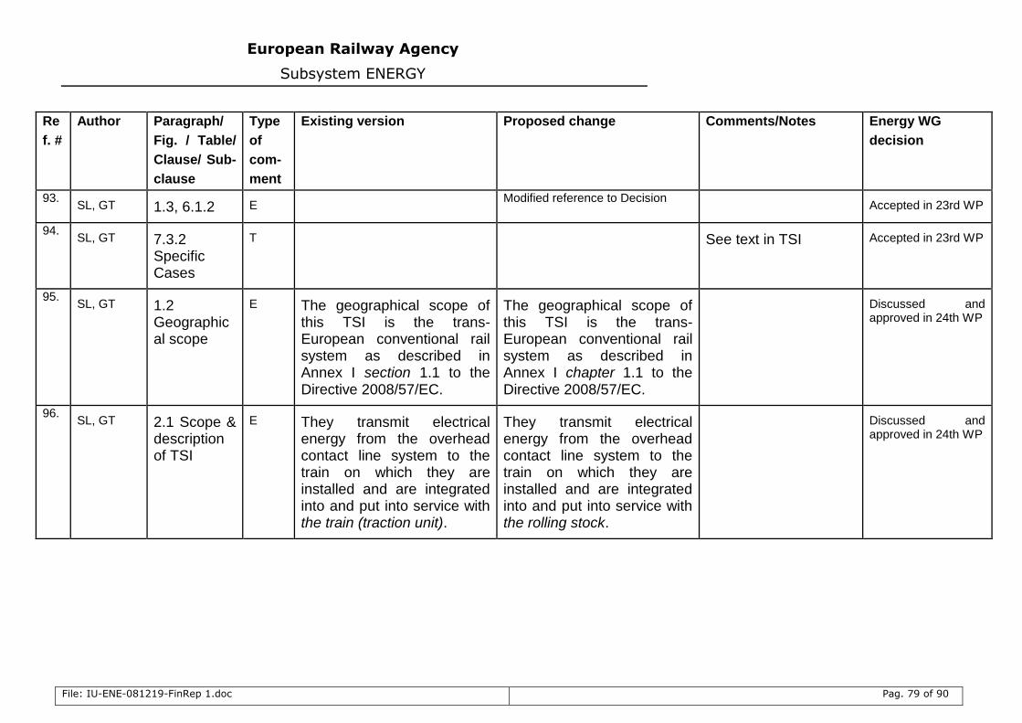
European Railway Agency
Subsystem ENERGY
File: IU-ENE-081219-FinRep 1.doc Pag. 79 of 90
Re
f. #
Author Paragraph/
Fig. / Table/
Clause/ Sub-
clause
Type
of
com-
ment
Existing version Proposed change Comments/Notes Energy WG
decision
93. SL, GT 1.3, 6.1.2 E
Modified reference to Decision Accepted in 23rd WP
94. SL, GT 7.3.2
Specific Cases
T
See text in TSI Accepted in 23rd WP
95. SL, GT 1.2
Geographical scope
E The geographical scope of this TSI is the trans-European conventional rail system as described in Annex I section 1.1 to the Directive 2008/57/EC.
The geographical scope of this TSI is the trans-European conventional rail system as described in Annex I chapter 1.1 to the Directive 2008/57/EC.
Discussed and approved in 24th WP
96. SL, GT 2.1 Scope &
description of TSI
E They transmit electrical energy from the overhead contact line system to the train on which they are installed and are integrated into and put into service with the train (traction unit).
They transmit electrical energy from the overhead contact line system to the train on which they are installed and are integrated into and put into service with the rolling stock.
Discussed and approved in 24th WP
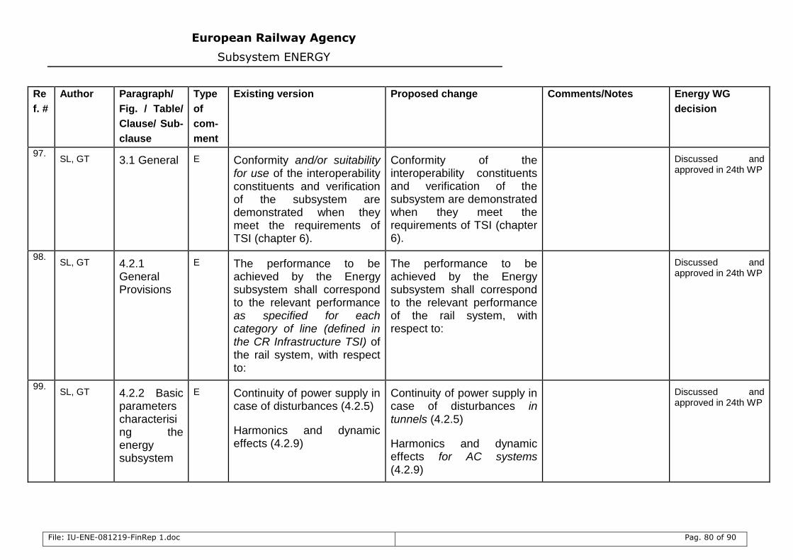
European Railway Agency
Subsystem ENERGY
File: IU-ENE-081219-FinRep 1.doc Pag. 80 of 90
Re
f. #
Author Paragraph/
Fig. / Table/
Clause/ Sub-
clause
Type
of
com-
ment
Existing version Proposed change Comments/Notes Energy WG
decision
97. SL, GT 3.1 General E Conformity and/or suitability
for use of the interoperability constituents and verification of the subsystem are demonstrated when they meet the requirements of TSI (chapter 6).
Conformity of the interoperability constituents and verification of the subsystem are demonstrated when they meet the requirements of TSI (chapter 6).
Discussed and approved in 24th WP
98. SL, GT 4.2.1
General Provisions
E The performance to be achieved by the Energy subsystem shall correspond to the relevant performance as specified for each category of line (defined in the CR Infrastructure TSI) of the rail system, with respect to:
The performance to be achieved by the Energy subsystem shall correspond to the relevant performance of the rail system, with respect to:
Discussed and approved in 24th WP
99. SL, GT 4.2.2 Basic
parameters characterising the energy subsystem
E Continuity of power supply in case of disturbances (4.2.5)
Harmonics and dynamic effects (4.2.9)
Continuity of power supply in case of disturbances in tunnels (4.2.5)
Harmonics and dynamic effects for AC systems (4.2.9)
Discussed and approved in 24th WP
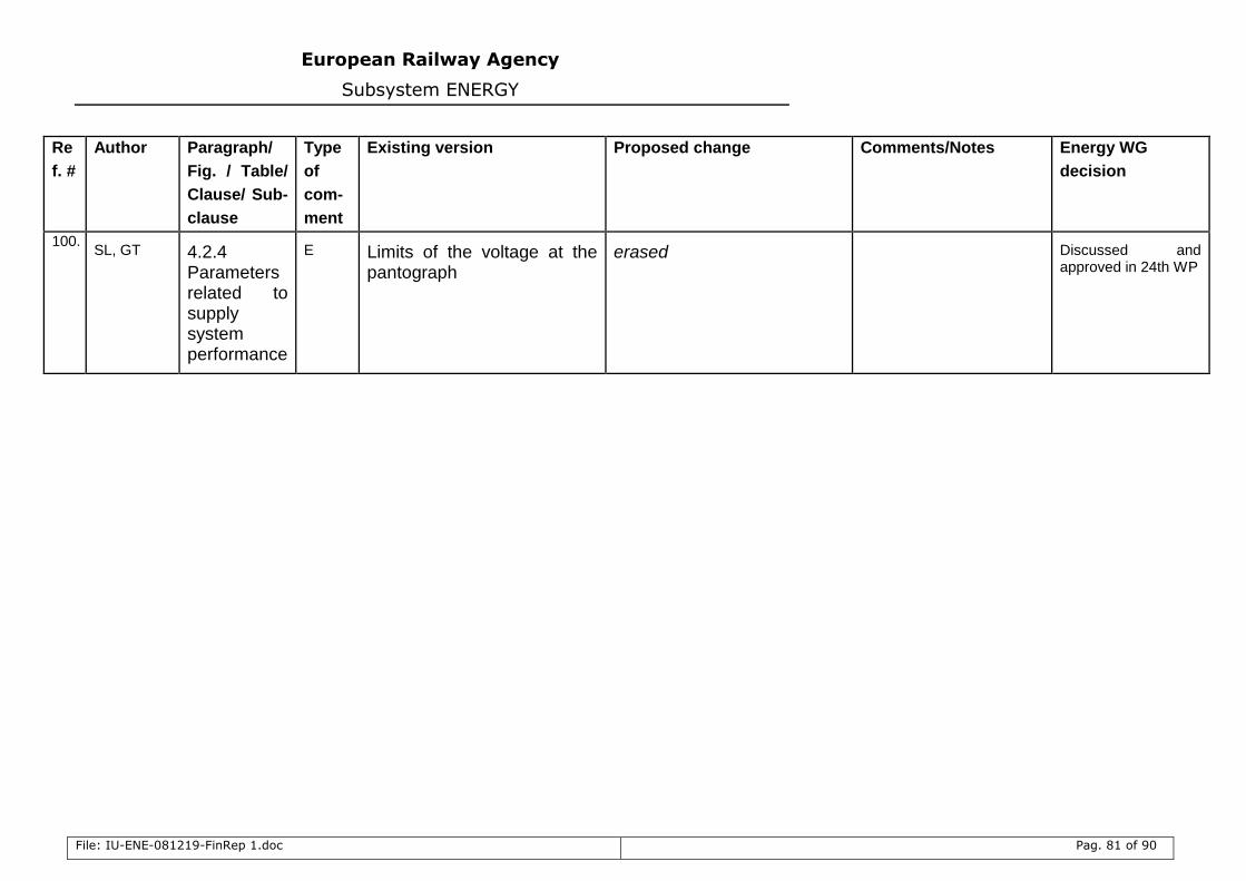
European Railway Agency
Subsystem ENERGY
File: IU-ENE-081219-FinRep 1.doc Pag. 81 of 90
Re
f. #
Author Paragraph/
Fig. / Table/
Clause/ Sub-
clause
Type
of
com-
ment
Existing version Proposed change Comments/Notes Energy WG
decision
100. SL, GT 4.2.4
Parameters related to supply system performance
E Limits of the voltage at the pantograph
erased Discussed and approved in 24th WP
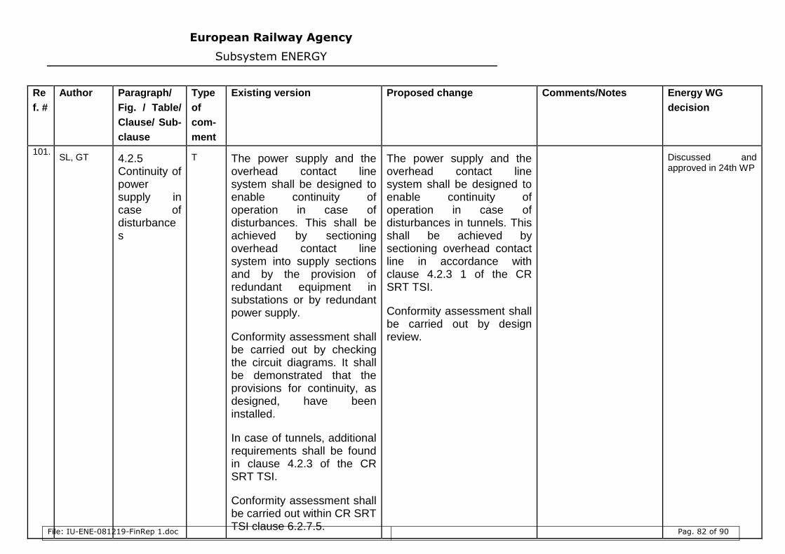
European Railway Agency
Subsystem ENERGY
File: IU-ENE-081219-FinRep 1.doc Pag. 82 of 90
Re
f. #
Author Paragraph/
Fig. / Table/
Clause/ Sub-
clause
Type
of
com-
ment
Existing version Proposed change Comments/Notes Energy WG
decision
101. SL, GT 4.2.5
Continuity of power supply in case of disturbances
T The power supply and the overhead contact line system shall be designed to enable continuity of operation in case of disturbances. This shall be achieved by sectioning overhead contact line system into supply sections and by the provision of redundant equipment in substations or by redundant power supply.
Conformity assessment shall be carried out by checking the circuit diagrams. It shall be demonstrated that the provisions for continuity, as designed, have been installed.
In case of tunnels, additional requirements shall be found in clause 4.2.3 of the CR SRT TSI.
Conformity assessment shall be carried out within CR SRT TSI clause 6.2.7.5.
The power supply and the overhead contact line system shall be designed to enable continuity of operation in case of disturbances in tunnels. This shall be achieved by sectioning overhead contact line in accordance with clause 4.2.3 1 of the CR SRT TSI.
Conformity assessment shall be carried out by design review.
Discussed and approved in 24th WP
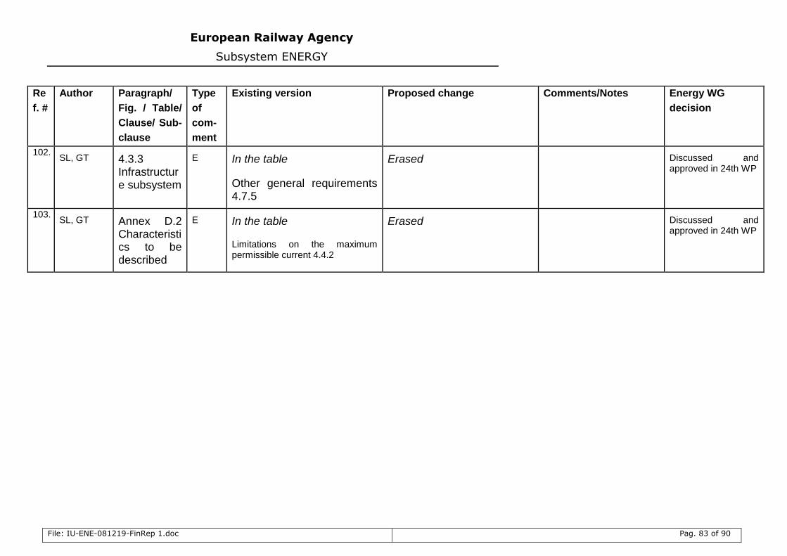
European Railway Agency
Subsystem ENERGY
File: IU-ENE-081219-FinRep 1.doc Pag. 83 of 90
Re
f. #
Author Paragraph/
Fig. / Table/
Clause/ Sub-
clause
Type
of
com-
ment
Existing version Proposed change Comments/Notes Energy WG
decision
102. SL, GT 4.3.3
Infrastructure subsystem
E In the table
Other general requirements 4.7.5
Erased Discussed and approved in 24th WP
103. SL, GT Annex D.2
Characteristics to be described
E In the table
Limitations on the maximum permissible current 4.4.2
Erased Discussed and approved in 24th WP
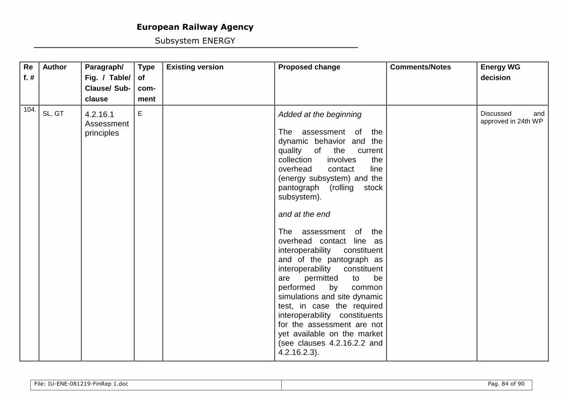
European Railway Agency
Subsystem ENERGY
File: IU-ENE-081219-FinRep 1.doc Pag. 84 of 90
Re
f. #
Author Paragraph/
Fig. / Table/
Clause/ Sub-
clause
Type
of
com-
ment
Existing version Proposed change Comments/Notes Energy WG
decision
104. SL, GT 4.2.16.1
Assessment principles
E Added at the beginning
The assessment of the dynamic behavior and the quality of the current collection involves the overhead contact line (energy subsystem) and the pantograph (rolling stock subsystem).
and at the end
The assessment of the overhead contact line as interoperability constituent and of the pantograph as interoperability constituent are permitted to be performed by common simulations and site dynamic test, in case the required interoperability constituents for the assessment are not yet available on the market (see clauses 4.2.16.2.2 and 4.2.16.2.3).
Discussed and approved in 24th WP
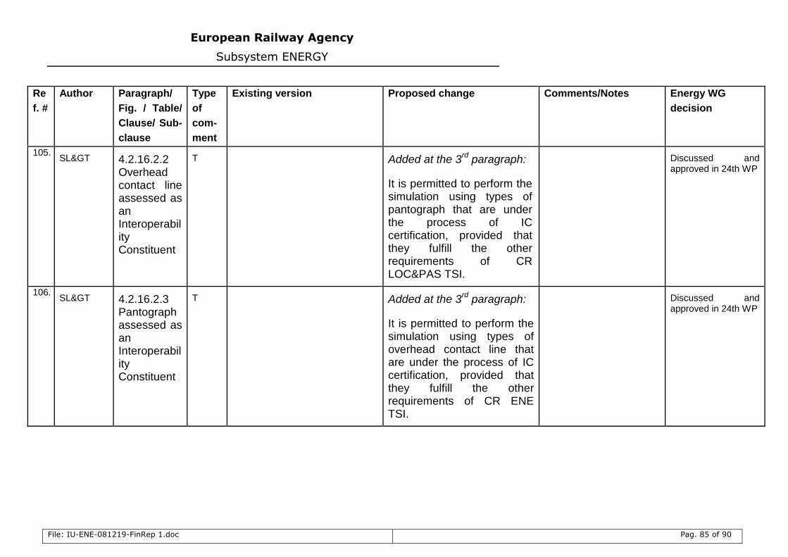
European Railway Agency
Subsystem ENERGY
File: IU-ENE-081219-FinRep 1.doc Pag. 85 of 90
Re
f. #
Author Paragraph/
Fig. / Table/
Clause/ Sub-
clause
Type
of
com-
ment
Existing version Proposed change Comments/Notes Energy WG
decision
105. SL> 4.2.16.2.2
Overhead contact line assessed as an Interoperability Constituent
T Added at the 3rd
paragraph:
It is permitted to perform the simulation using types of pantograph that are under the process of IC certification, provided that they fulfill the other requirements of CR LOC&PAS TSI.
Discussed and approved in 24th WP
106. SL> 4.2.16.2.3
Pantograph assessed as an Interoperability Constituent
T Added at the 3rd
paragraph:
It is permitted to perform the simulation using types of overhead contact line that are under the process of IC certification, provided that they fulfill the other requirements of CR ENE TSI.
Discussed and approved in 24th WP
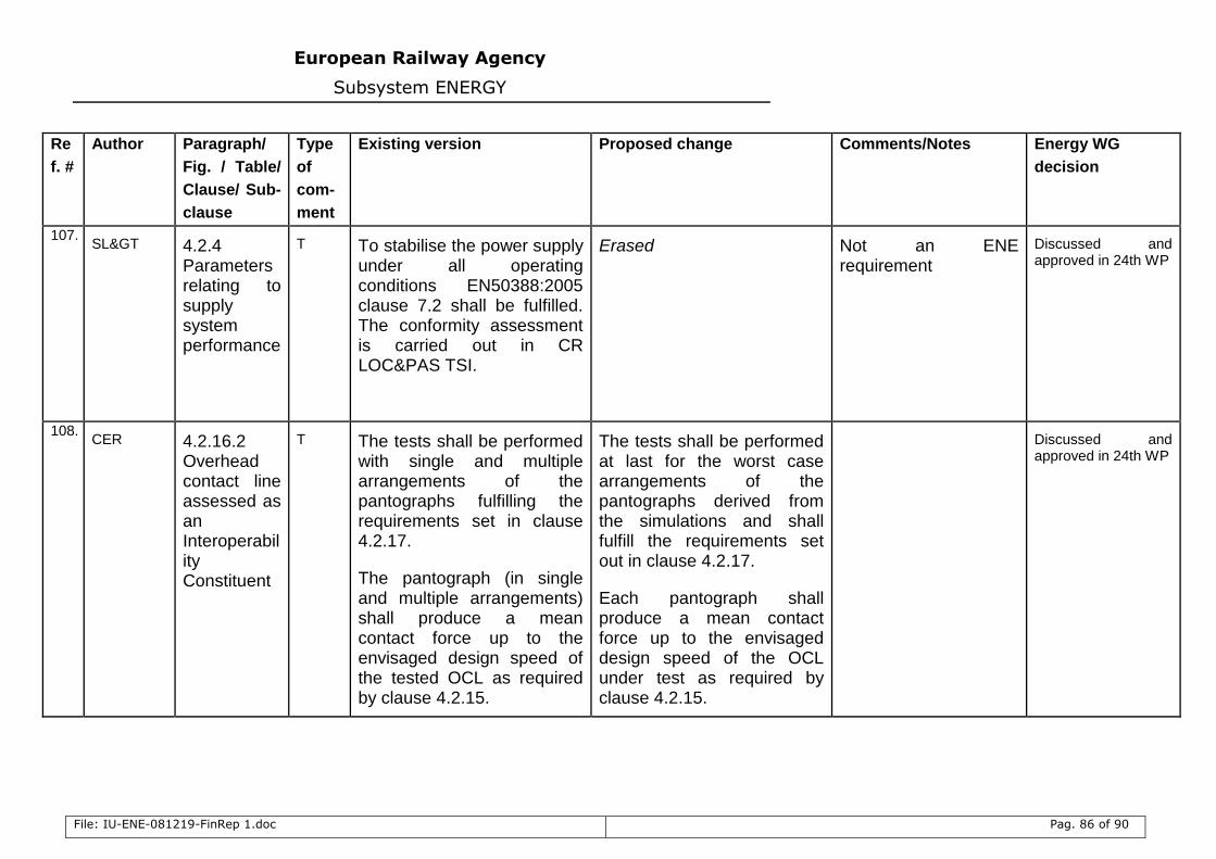
European Railway Agency
Subsystem ENERGY
File: IU-ENE-081219-FinRep 1.doc Pag. 86 of 90
Re
f. #
Author Paragraph/
Fig. / Table/
Clause/ Sub-
clause
Type
of
com-
ment
Existing version Proposed change Comments/Notes Energy WG
decision
107. SL> 4.2.4
Parameters relating to supply system performance
T To stabilise the power supply under all operating conditions EN50388:2005 clause 7.2 shall be fulfilled. The conformity assessment is carried out in CR LOC&PAS TSI.
Erased
Not an ENE requirement
Discussed and approved in 24th WP
108. CER 4.2.16.2
Overhead contact line assessed as an Interoperability Constituent
T The tests shall be performed with single and multiple arrangements of the pantographs fulfilling the requirements set in clause 4.2.17.
The pantograph (in single and multiple arrangements) shall produce a mean contact force up to the envisaged design speed of the tested OCL as required by clause 4.2.15.
The tests shall be performed at last for the worst case arrangements of the pantographs derived from the simulations and shall fulfill the requirements set out in clause 4.2.17.
Each pantograph shall produce a mean contact force up to the envisaged design speed of the OCL under test as required by clause 4.2.15.
Discussed and approved in 24th WP
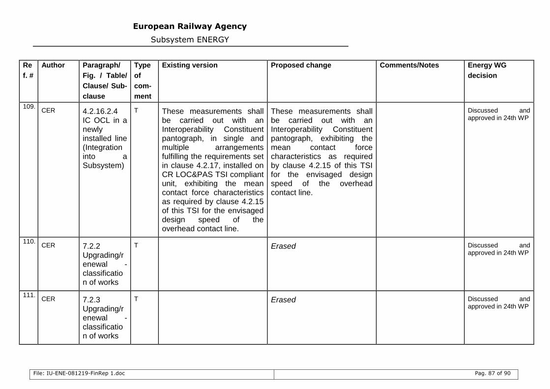
European Railway Agency
Subsystem ENERGY
File: IU-ENE-081219-FinRep 1.doc Pag. 87 of 90
Re
f. #
Author Paragraph/
Fig. / Table/
Clause/ Sub-
clause
Type
of
com-
ment
Existing version Proposed change Comments/Notes Energy WG
decision
109. CER 4.2.16.2.4
IC OCL in a newly installed line (Integration into a Subsystem)
T These measurements shall be carried out with an Interoperability Constituent pantograph, in single and multiple arrangements fulfilling the requirements set in clause 4.2.17, installed on CR LOC&PAS TSI compliant unit, exhibiting the mean contact force characteristics as required by clause 4.2.15 of this TSI for the envisaged design speed of the overhead contact line.
These measurements shall be carried out with an Interoperability Constituent pantograph, exhibiting the mean contact force characteristics as required by clause 4.2.15 of this TSI for the envisaged design speed of the overhead contact line.
Discussed and approved in 24th WP
110. CER 7.2.2
Upgrading/renewal - classification of works
T Erased Discussed and approved in 24th WP
111. CER 7.2.3
Upgrading/renewal - classification of works
T Erased Discussed and approved in 24th WP
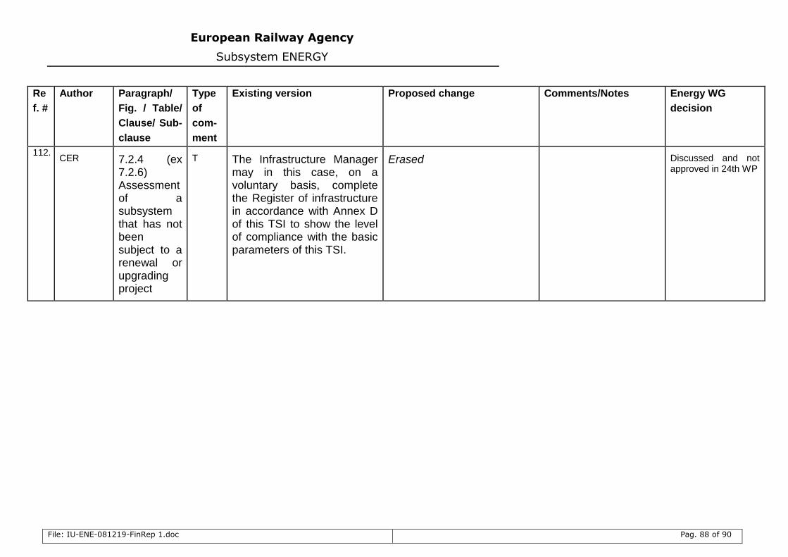
European Railway Agency
Subsystem ENERGY
File: IU-ENE-081219-FinRep 1.doc Pag. 88 of 90
Re
f. #
Author Paragraph/
Fig. / Table/
Clause/ Sub-
clause
Type
of
com-
ment
Existing version Proposed change Comments/Notes Energy WG
decision
112. CER 7.2.4 (ex
7.2.6) Assessment of a subsystem that has not been subject to a renewal or upgrading project
T The Infrastructure Manager may in this case, on a voluntary basis, complete the Register of infrastructure in accordance with Annex D of this TSI to show the level of compliance with the basic parameters of this TSI.
Erased Discussed and not approved in 24th WP
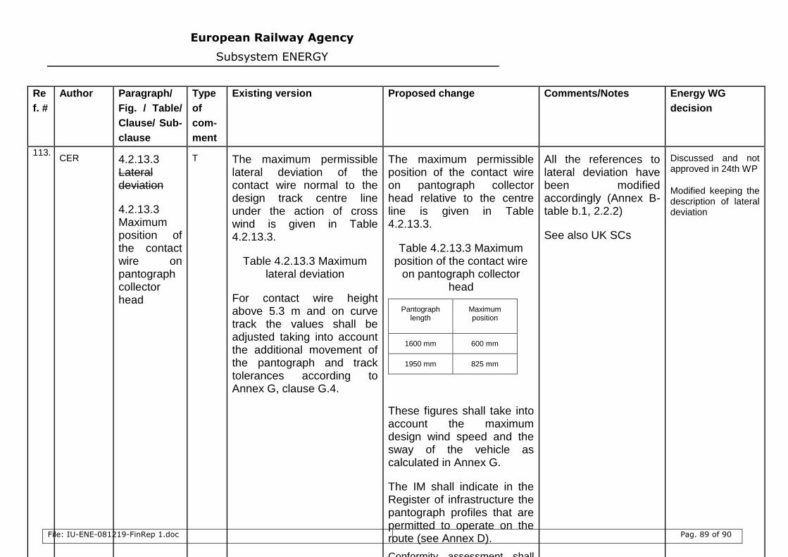
European Railway Agency
Subsystem ENERGY
File: IU-ENE-081219-FinRep 1.doc Pag. 89 of 90
Re
f. #
Author Paragraph/
Fig. / Table/
Clause/ Sub-
clause
Type
of
com-
ment
Existing version Proposed change Comments/Notes Energy WG
decision
113. CER 4.2.13.3
Lateral deviation
4.2.13.3 Maximum position of the contact wire on pantograph collector head
T The maximum permissible lateral deviation of the contact wire normal to the design track centre line under the action of cross wind is given in Table 4.2.13.3.
Table 4.2.13.3 Maximum lateral deviation
For contact wire height above 5.3 m and on curve track the values shall be adjusted taking into account the additional movement of the pantograph and track tolerances according to Annex G, clause G.4.
The maximum permissible position of the contact wire on pantograph collector head relative to the centre line is given in Table 4.2.13.3.
Table 4.2.13.3 Maximum position of the contact wire
on pantograph collector head
Pantograph length
Maximum position
1600 mm 600 mm
1950 mm 825 mm
These figures shall take into account the maximum design wind speed and the sway of the vehicle as calculated in Annex G.
The IM shall indicate in the Register of infrastructure the pantograph profiles that are permitted to operate on the route (see Annex D).
Conformity assessment shall
All the references to lateral deviation have been modified accordingly (Annex B-table b.1, 2.2.2)
See also UK SCs
Discussed and not approved in 24th WP
Modified keeping the description of lateral deviation
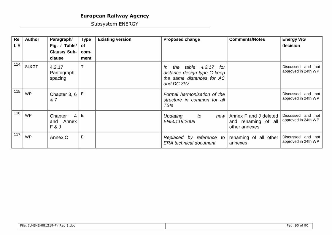
European Railway Agency
Subsystem ENERGY
File: IU-ENE-081219-FinRep 1.doc Pag. 90 of 90
Re
f. #
Author Paragraph/
Fig. / Table/
Clause/ Sub-
clause
Type
of
com-
ment
Existing version Proposed change Comments/Notes Energy WG
decision
114. SL> 4.2.17
Pantograph spacing
T In the table 4.2.17 for distance design type C keep the same distances for AC and DC 3kV
Discussed and not approved in 24th WP
115. WP Chapter 3, 6
& 7
E Formal harmonisation of the structure in common for all TSIs
Discussed and not approved in 24th WP
116. WP Chapter 4
and Annex F & J
E Updating to new EN50119:2009
Annex F and J deleted and renaming of all other annexes
Discussed and not approved in 24th WP
117. WP Annex C E Replaced by reference to
ERA technical document renaming of all other annexes
Discussed and not approved in 24th WP