interpretation of metal fab drawings - open oregon
TRANSCRIPT

Interpretation of Metal Fab Drawings


Interpretation of Metal Fab Drawings
CAMEREN MORAN
OPEN OREGON EDUCATIONAL RESOURCES

Interpretation of Metal Fab Drawings by Cameren Moran is licensed under a Creative Commons Attribution 4.0 International License,except where otherwise noted.

Contents
1. Interpreting metal fab drawings 1
2. Blue Print Review 2
3. Joint types and Terminology 5
4. Basics of Welding Symbols 19
5. Supplementary Welding Symbols 25
6. Fillet Weld Symbols 32
7. Groove Welding Symbols 45
8. Plug Weld symbols 58
9. Spot, Seam, Stud Welding Symbols 65
10. Edge Weld Symbols 73
11. Process and Method 79
12. Pipe Symbols 82
13. Pipe Drawings 87


1. Interpreting metal fab drawings
Interpreting metal fab drawings is a course that introduces the principles of interpretation and application ofindustrial fabrication drawings. Basic principles and techniques of metal fabrication are introduced by planningand construction of fixtures used in fabrication from drawings. Basic tools and equipment for layout fitting ofwelded fabrications are utilized. Covers the use and application of the AWS welding symbols. This course willutilize blueprints and welding symbols and will apply them in classroom and in shop as practical assignments.
The largest reason for understanding this information is to communicate between all parties involved. Thiscould include the welder, engineer, quality control, as well as many more. This is a universal language thatprovides clear instructions for a quality part.
American Welding Society has created a detailed publication (Standard Symbols for Welding, Brazing, andNondestructive Examination AWS A2.4) that gives an extended amount of knowledge in this language.
Below is an overview of what the elements of a welding symbol may or may not include. The welding symbolprovides a visualization for the welder or those involved to be able to apply the applicable weld to the workpiece.
http://www.weldersuniverse.com/welding_symbols.html
Interpreting metal fab drawings | 1

2. Blue Print Review
Blue Print Reading ReviewUnderstanding blue prints is a vital skill in the metals industry. Whether it be as a structural welder, pipe fitter,
or quality control, this is the language that is universal for all individuals involved in a project.This chapter is here to recap some line types as well as visualizing blue prints and plans.Line Types1. Object LineA visible line is a thick line, without breaks, that indicates all edges and visible surfaces of an object. An object
line may also be called a visible line.
2. Hidden LineA hidden line is a medium weight line, made of short dashes, to show edges, surfaces and corners which
cannot be seen. Sometimes they are used to make a drawing easier to understand. Often they are omitted.
3. Section LineSection lines are used on a drawing to show how an object would look if it were sectioned, or cut apart, to give
a better picture of shape or internal construction. Section lines are very thin (size), and are usually drawn at anangle of 45 degrees. They show the cut surface of an object in a sectional view. Sections and section lines willbe explained in BPR 7.
4. Center LineCenter lines are used to indicate the centers of holes, arcs, and symmetrical objects. They are very thin (size),
long-short-long kinds of lines. (More detail needed?)
5. Dimension LineDimension lines are thin lines with a break for entering a measurement of some sort. The ends of the lines
will also have an arrow head pointing to an extension line (below.)
6. Extension Line
2 | Blue Print Review

Extension lines are also thin lines, showing the limits of dimensions. Dimension line arrowheads touchextension lines.
7. Leader LineLeaders are more thin lines used to point to an area of a drawing requiring a note for explanation.
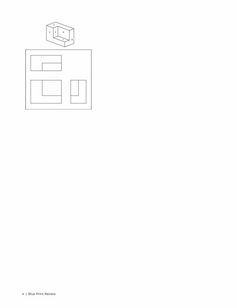
Visualizing partsAs a welder it is imperative that you can visualize the part you are building from the print. This is not always
an easy task. Prints may have a variety of parts or are not detailed as well as they should be but being able todistinguish sides and faces can help decipher these harder prints.
Surface identification quiz
Blue Print Review | 3
4 | Blue Print Review

3. Joint types and Terminology
Terminology of joints may play a large role in communication with supervisors and others working on the sameweldment. Understanding the concepts associated with joint design as well as identification of parts is criticalfor any metal worker.
Joint TypesThere are 5 basic joint types used in the metal fabrication field:Butt Joint: A joint type in which the butting ends of one or more work pieces are aligned in approximately
the same plane. A butt joint has a possibility of many prepared faces. We will talk about these in subsequentchapters. Represented is a square groove butt joint.
Possible Welds for a Butt Joint:Square GrooveBevel GrooveV GrooveJ GrooveU GrooveFlare Bevel GrooveFlare Vee GrooveFlanged EdgeScarf (Brazed Joint)Corner Joint: being one of the most popular welds in the sheet metal industry the corner joint is used on the
outer edge of the piece. This weld is a type of joint that comes together at right angles between two metal parts
Joint types and Terminology | 5

to form an L. These are common in the construction of boxes, box frames and similar fabrications. There arevariations of a corner joint, shown is a closed corner joint.
Possible welds for a corner joint:FilletEdge FlangeCorner FlangeBevel GrooveV Groove Flare BevelFlare V GrooveJ GrooveU GrooveSquare GrooveSeamSpotProjectionSlotPlugLap Joint: A joint between two overlapping members in parallel planes.
6 | Joint types and Terminology

Possible welds for lap joint:FilletBevel GrooveSquare GrooveFlare V grooveJ GroovePlugSlotSpotProjectionSeam*BrazeTee Joint: A joint which are two pieces of metal are perpendicular to each other. This is one of the most
common joint that will be encountered in the metal fabrication industry.
Joint types and Terminology | 7

Possible welds for a Tee joint:FilletBevel GrooveSquare GrooveFlare V grooveJ GroovePlugSlotSpotProjectionSeam
8 | Joint types and Terminology

Edge Joint: A joint formed by uniting two edges or two surfaces (as by welding) especially making a corner.
Joint types and Terminology | 9

Possible welds for edge joints:Square GrooveBevel GrooveV GrooveEdgeJ GrooveU GrooveFlare Bevel GrooveFlare V GrooveCorner FlangeEdge FlangeSeamJoints may be left as cut but some may have a prepared surface that is determined by the engineer, designer
or welder. This is commonly seen with a Butt weld when the members to be joined are larger in thickness. Thiswill be visited in subsequent chapters.
Joint terminologyOutside of specific joint types there are some terms that will play a role in deciding the correct procedure for
welding or prepping the member(s) of a weldment.Joint Root- This is the area which is in closest proximity to another member making the joint. This could be
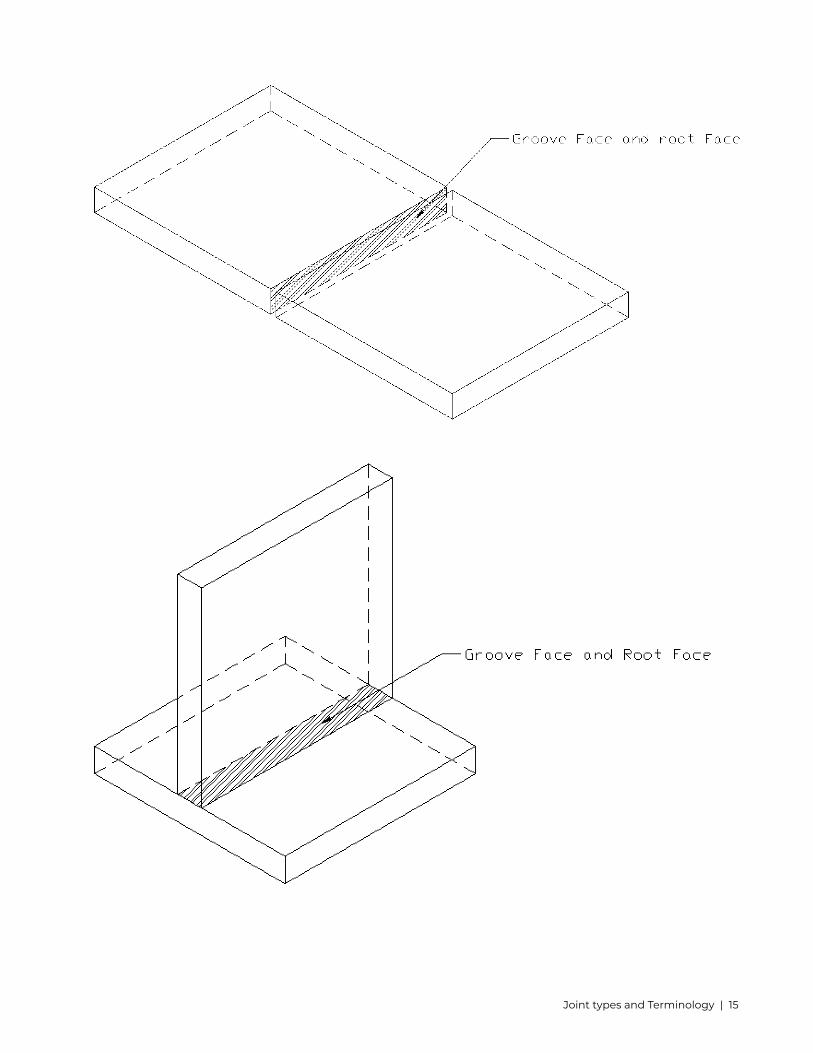
viewed as a line, area, or a point depending on the view in front of you.Groove Face- The surface within the groove the weld may be applied to. This can be measured at an angle
from the surface of the part to the root edge.Root Edge- This is a root face that has no width (land) to it. In GTAW it is commonly referred to as a knife edge
preparation.Root Face- This part of the prepped member is the portion of the groove face that is also within the joint root.
This is commonly called a flat or land in the industry. This is usually a predetermined size even though the sizeis not always called out. If you take the overall thickness of the member and subtract the groove depth you willbe left with the root face depth.
Bevel Angle- an angle between the bevel of a member and a perpendicular plane in relation to the surface.This may be only equal to half of a groove angle if the opposite joining member is also prepped. If only a singlemember is prepped this is also considered the groove angle.
Depth of Bevel- the distance from the surface of the base metal to the root edge or beginning of the rootface.
Groove Angle- an included angle of the groove between work pieces. If both members are prepared this angleis from groove face to groove face. This dimension is shown in degrees above or below the welding symboldepending on if it is arrow side or other side designation.
Groove Radius-This pertains specifically to J or U groove welds as these have a radius most commonly specificby machining.
Root Opening- a gap between two joining members.Joint Root Examples. Some may be shown with hatching.
10 | Joint types and Terminology

Joint types and Terminology | 11

12 | Joint types and Terminology

Joint types and Terminology | 13

Groove Face, Root Edge, Root Face examples. Some are shown with or without hatching to better depict avisual.
14 | Joint types and Terminology
Joint types and Terminology | 15

Shown below are examples of bevel angle, groove angle, depth of bevel, groove radius, and root opening.
16 | Joint types and Terminology

Joint types and Terminology | 17

18 | Joint types and Terminology

4. Basics of Welding Symbols
Understanding Weld vs. Welding symbolA weld symbol is not the same as a welding symbol. The weld symbol specifies the type of weld to be applied
to a part. The welding symbol is made of several parts including the reference line, arrow, and weld symbolwhen required. The symbols in this book are a representation of what weld and welding symbols look like. Thereare specific design requirements when used in accordance to a blueprint.
Reference Line and ArrowThere are two parts that make up the main body of a welding symbol. These include the reference line and
the arrow. The horizontal line that makes up the main body is called the reference line. This is the anchor towhich all the other welding symbols are tied. The information that is pertinent for making the weld are placeon the reference line in specific places. The arrow connects the reference line to the joint in which the weld(s)is (are) to be made. There are several combinations of the reference line and arrow, but the reference line willalways be placed in a horizontal position. This symbol is also always read from the left to the right. If you havebeen around blueprints the arrow may look a lot like a leader line. They are not the same thing so be mindfulwhen reviewing welding symbols.
The reference line may include what is called the tail. This looks like the letter V turned sideways. Such asthis >. This tail gives an area to write specifics about what weld process, welding procedure, and even materialspecifications are required for that specific welding symbol.
Basics of Welding Symbols | 19

Arrow vs Other SidePlacement of the weld will depend on placement of the symbol above or below the reference line. If the
symbol has been placed above the reference line this is calling for the other side. If it is placed below thereference line this is calling for the arrow side. Other and arrow side define exactly what it is calling for. If thearrow is pointing to the right side of the joint the weld will be placed on the right side if an arrow side weld iscalled out. If the arrow is pointing at the right side of the joint and another side weld is called then the weld willbe applied to the left side of the part.
20 | Basics of Welding Symbols

If a weld is to be placed on the other side of a joint a symbol will be placed above the reference line.
If a weld is to be placed on the arrow side of a joint the symbol will be placed below the reference line.
Basics of Welding Symbols | 21

It is very important to understand the difference of these two sides as it could finish a product or if doneincorrectly send it back to be reworked in order to get the correct outcome. The concept behind this may seemvery simple at the moment but as we work through this book and start adding more elements to the weldingsymbol it may become more taxing on the thought process. The most important thing to do is break it downpiece by piece and truly understand what the symbol is asking/ requiring for the weld.
At times there may be multiple reference lines. If this is the case it is important to remember the orderof which the welding is to occur. The reference line nearest the arrow will be the first operation, followed by thesecond, and so on until all operations are complete.
Symbol Fundamental Quiz
22 | Basics of Welding Symbols

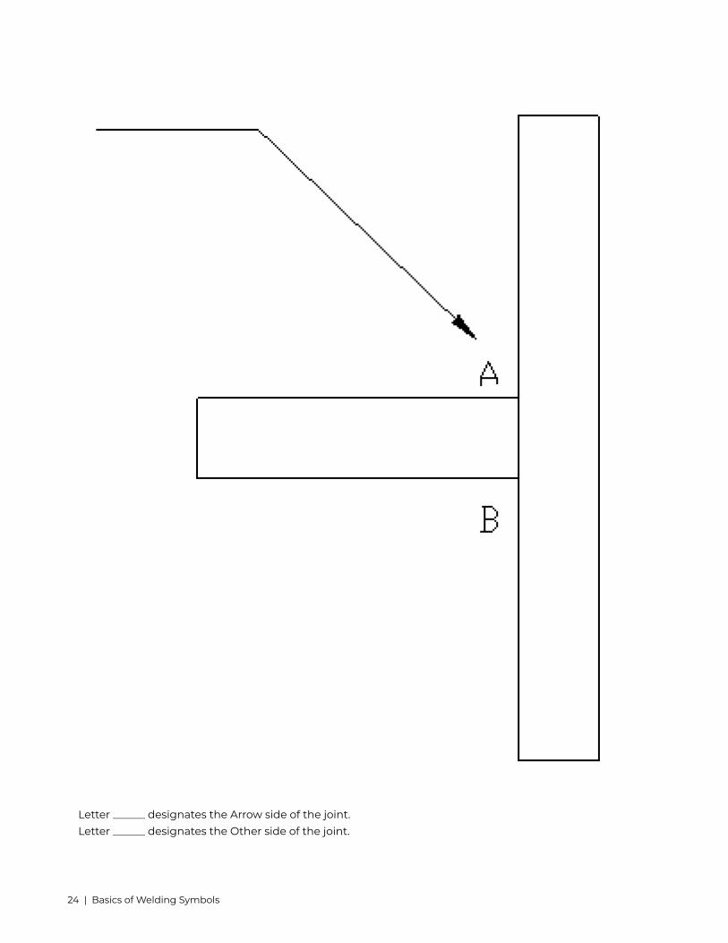
Label the image below with the appropriate letter (arrow/other) designation.
Letter ______ designates the Arrow side of the joint.Letter ______ designates the Other side of the joint.
Basics of Welding Symbols | 23
Letter ______ designates the Arrow side of the joint.Letter ______ designates the Other side of the joint.
24 | Basics of Welding Symbols

5. Supplementary Welding Symbols
These are symbols that are added onto a weld symbol to give further instruction or knowledge of the finalproduct.
Weld all aroundThis symbol is simply a circle at the junction of the arrow and the reference line. This indicates that on a part
that a weld could be completed around an entire joint. A common place you could see this is the junction of asquare or round tube and a plate.
Field WeldThe symbol is a flag that will be at the junction of the arrow and reference line. This indicates that the part
while may be assembled in a shop setting, its final welding procedures will be completed in the field duringinstallation. The flag itself should point in the direction of the tail (end of reference line.) It can also be placedabove or below the reference line for an other or arrow side specification.
Supplementary Welding Symbols | 25

Melt ThroughMelt through is most commonly associated with a groove weld. This is indicating you are achieving 100%
penetration with a root reinforcement. This symbol can also be seen when sheet metal is being welded andthere is an implied melt through in seams and joints.
26 | Supplementary Welding Symbols

Supplementary Welding Symbols | 27

Melt through may include a finishing contour as well as finishing method as parts are often cleaned up beforethey are sent to be painted, powder coated, or put into service.
Consumable InsertA consumable insert symbol is used when an insert is used within a welded joint that becomes part of the
weld. These are commonly specified in shape, size, and material. The symbol is placed on the opposite side ofthe groove weld symbol. The consumable insert class must be placed in the tail of the welding symbol. Thisclass is defined by the American Welding Society.
28 | Supplementary Welding Symbols

BackingA backing strip is specified by placing a rectangle on the opposite side of the reference line from the groove
weld symbol. If the backing must be removed after the welding operation has been finished, the letter R mustbe placed inside of the backing symbol. Material to be used as well as the dimensions must be placed in the tailof the symbol or somewhere on the drawing.
SpacerA spacer may be used on a double groove weld. In this case both the top and bottom are prepped and a
Supplementary Welding Symbols | 29

spacer is added to the middle of the groove. The symbol is a rectangle the breaks the reference line. A note onthe print or in the tail can specify material and dimensions.
Weld contourThere are 3 symbols used for specifying the contour finish of a weld. This is the final appearance of a weld as it
goes into service. These are commonly associated with fillet welds but sometimes will present themselves withgroove welds. If a “flat” symbol is used with a groove weld it will then be called a flush contour rather than flat.
Contour symbols may also include yet another element which will show to the right of the fillet weld symbolabove the contour. These are letter designations which will be for finishing methods.
C- ChippingG- GrindingH- HammeringM- MachiningP- PlanishingR- RollingU- Unspecified
30 | Supplementary Welding Symbols

Shown is a fillet weld to be applied to the other side with a flat contour by grinding.
Supplementary Welding Symbols | 31

6. Fillet Weld Symbols
Fillet welds are one of the most common weld types in the industry. This weld is used when the joint has twomembers coming together to form an intersection of commonly 90 degrees. These welds can be applied onvarying angles but this would be the most prominent.
A fillet weld symbol can be used with an arrow side (below reference line) other side (above reference line)significance or on both sides (both sides of the reference line.) When a fillet weld is required on both sides ofthe reference line it is called a double fillet weld. The vertical leg of the symbol will always be placed to the leftregardless of which way the arrow is pointing.
Fillet welds may have a size associated with them. This size is called out on the left side of the symbol beforethe vertical side. The size is indicating the leg length of the weld. If a single size is called out this is specifyingthat weld should have equal leg sizes. If it is an equal leg fillet weld it is not common to dimension it on theprint as shown below for demonstration purpose.
32 | Fillet Weld Symbols

If a double fillet weld is called out the size will be shown for both sides of the joint, depending on the partthese welds could vary in size so it is necessary to provide this information.
There are times when an unequal leg fillet weld is called out. In this situation the part must be dimensioned
Fillet Weld Symbols | 33

in order to apply the correct leg size to the right member being welded. This may include only one of the twoleg lengths. If there were no indication of which leg is which the part could be welded incorrectly.
Sometimes fillet welds will not be shown with a size but will rather have a note in the tail of the symbol thatgives required information for size. This is common when fillet welds will all be the same size.
In the case of the length of a weld, this may or may not have a dimension associated with it. If the welddoes not have a dimension the weld will be the continuous length of the joint. Whether the part is 2” or 60” longif it has no dimension the weld will run the length of the joint. A weld may be applied only to a specific length of
34 | Fillet Weld Symbols

a joint. This must be shown in the weld symbol to communicate the information between individuals. The weldlength will be provided on the right side of the fillet weld symbol.
Fillet Weld Symbols | 35

36 | Fillet Weld Symbols
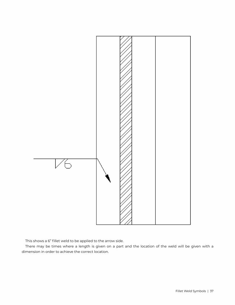
This shows a 6” fillet weld to be applied to the arrow side.There may be times where a length is given on a part and the location of the weld will be given with a
dimension in order to achieve the correct location.
Fillet Weld Symbols | 37

Hatching lines may be used to indicate the length of a weld instead of using a dimension on the weld symbolitself.
There are instances when a weld may change direction because of part geometry. If this happens it willbe called out using multiple arrows off of one reference line.
38 | Fillet Weld Symbols

When a weld is not required to be continuous it is common to apply an intermittent weld. This meansthat there are gaps between the termination of one weld and the start of the next. These are called weldsegments. They are commonly referred to as skip welds in the industry.
When using an intermittent weld there is a call out specified for the length of the weld and also the pitch thatis to be applied. When this is shown on the right side of the symbol and it is called as the length of segmenta hyphen and then the pitch of the welds. The pitch of the weld is measured as center to center of the nextsegment. (Ex. 1-2)
Fillet Weld Symbols | 39

At times that there are welds on both sides of the joint and they are intermittent, this now becomes chainintermittent welding. This can be seen on long sections of a tee joint that isn’t under a large amount of stress.
40 | Fillet Weld Symbols

When an intermittent fillet is not a chain weld it will then be called out as a staggered intermittent fillet weld.The welds will be placed on both sides of the joint but it will be offset with one another. This offset shows on thereference line as well. It could be staggered in either direction on the reference line. Dimensions of these weldsmust be specified on both sides of the reference line.
Fillet Weld Symbols | 41

If the weld is only to be intermittent on one side and a continuous weld on the other the symbol must bedimensioned individually.
42 | Fillet Weld Symbols

Not all pitch will be the same, or necessarily common space. You must be able to calculate the spacingbetween weld stops and weld starts in order to apply the correct welds to the specification. An easy way to findthis distance is simply subtract the pitch from the weld length (segment.)
7 inches (pitch) – 3 inches (length of segment) = 4 inches (spacing in between welds)At times there will be a mixture of continuous welding as well as intermittent welding. If this occurs the
spacing between these segments will all be the same.
If this combination occurs welding symbols should specify continuous and intermittent on the same side ofthe joint. These are also often dimensioned.
Fillet Weld Symbols | 43
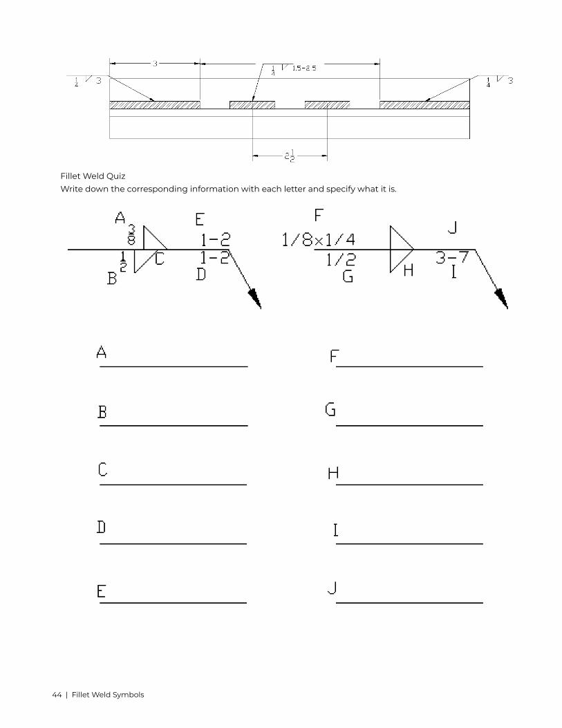
Fillet Weld QuizWrite down the corresponding information with each letter and specify what it is.
44 | Fillet Weld Symbols

7. Groove Welding Symbols
A groove weld will be used when to parts come together in the same plane. These welds will be applied in abutt joint and may have a preparation or not before welding. This is the reason there are several types of groovewelding symbols.
The symbols for these grooves are nearly identical to the symbols that represent them.When a weld is to be applied to only one side of a joint it will be called a single groove weld. For example below
is a welding symbol of a single V-Groove weld on the other side. All single groove welds should be consideredcomplete joint penetration (CJP) unless otherwise specified.
Groove Welding Symbols | 45

If a weld is to be applied to both sides of the joint this is called a double groove weld. For example below is awelding symbol of a double bevel groove weld.
The theory behind the single groove weld and double groove weld translate to all of the groove weld symbols.It would be redundant to recreate all of these images.
46 | Groove Welding Symbols

What do these symbols call for?In some cases you will see a jog in the arrow. This is called a break in the arrow that will designate which side
of the joint will be required to have the preparation done to it. For example if a single bevel is to be applied tothe left side of the joint a broken arrow will be pointing specifically at that side of the joint.
Groove Welding Symbols | 47

If there was not an indicating arrow the welder or fitter would choose which side should be preparedaccording to their knowledge. This could be an issue if an engineer has specific needs for the part or weld.
QuizDraw the symbol representing the below groove and name it (don’t forget to specify which side of the joint is
prepared):
Draw the symbol for a V groove on the other side below:Groove weld dimensioning
There are several dimensions that may be added to a groove weld if it is needed. This can include agroove angle, root opening, a groove radius, depth of the groove preparation, and groove weld size. There aretimes that this information may not be included at all. This would mean that it is the welder’s discretion as tohow the part will be prepared and welded.
Groove angle is shown in degrees and will include all of the groove, if it is a V Groove it will be adimension from one groove face to the other. This can be confused with bevel angle. Bevel angle is only onehalf of a V groove. This dimension is shown within the weld symbol itself. There is a possibility for two differentangles if you are applying to a double groove weld. The arrow and other side do not have to necessarily matchin angles.
48 | Groove Welding Symbols

A groove weld is the most common weld to have a root opening. This is a gap that is predeterminedto have between two members to be welded. There is not always a root opening and this dimension can beomitted from the welding symbol. It is common to put a root opening on a part to ensure complete penetrationor even melt through. The melt through symbol is included in supplementary welding symbols.
Grooves that associate with U and J preparations are a rather special weld. These welds if done to correctstandards are machined with a specific radius of groove as well as root face. These dimensions must be shownin a detail or section view that is noted in the tail of the welding symbol.
The preparation of the groove may be called out for how deep you are to prepare the part. This is called thedepth of groove. V- Grooves, j- grooves, and u- grooves are the most commonly sized welds for depth. Althoughthis does not mean it cannot be applied to others. The dimension will be shown to the left of the weld symbol.
Groove Welding Symbols | 49

As we start adding more elements the symbols get fairly complicated looking. The easiest thing to do is slowdown and look at each individual piece and apply it to what we have learned. For example the below weld isa single V-groove weld on the other side. This weld has a ½ inch groove depth, 1/16inch root opening, and 90degree groove angle.
When using a groove depth that is not the full depth of the part we leave a flat area in the root. This area iscalled the root face. A more common term you will hear is the land. In the diagram above we have a ½ inchgroove depth and we have a ¾ inch part. This leaves us a ¼ inch root face.
Often associated with a groove weld is going to be the weld size. This weld size is the depth of
50 | Groove Welding Symbols
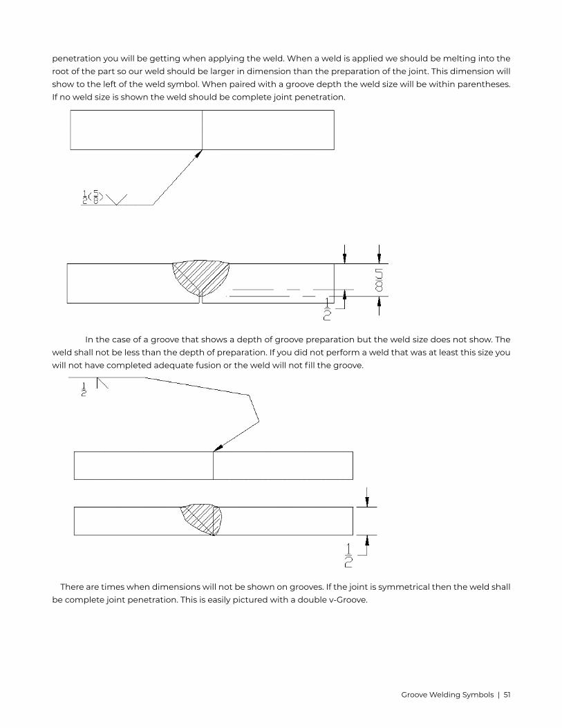
penetration you will be getting when applying the weld. When a weld is applied we should be melting into theroot of the part so our weld should be larger in dimension than the preparation of the joint. This dimension willshow to the left of the weld symbol. When paired with a groove depth the weld size will be within parentheses.If no weld size is shown the weld should be complete joint penetration.
In the case of a groove that shows a depth of groove preparation but the weld size does not show. Theweld shall not be less than the depth of preparation. If you did not perform a weld that was at least this size youwill not have completed adequate fusion or the weld will not fill the groove.
There are times when dimensions will not be shown on grooves. If the joint is symmetrical then the weld shallbe complete joint penetration. This is easily pictured with a double v-Groove.
Groove Welding Symbols | 51
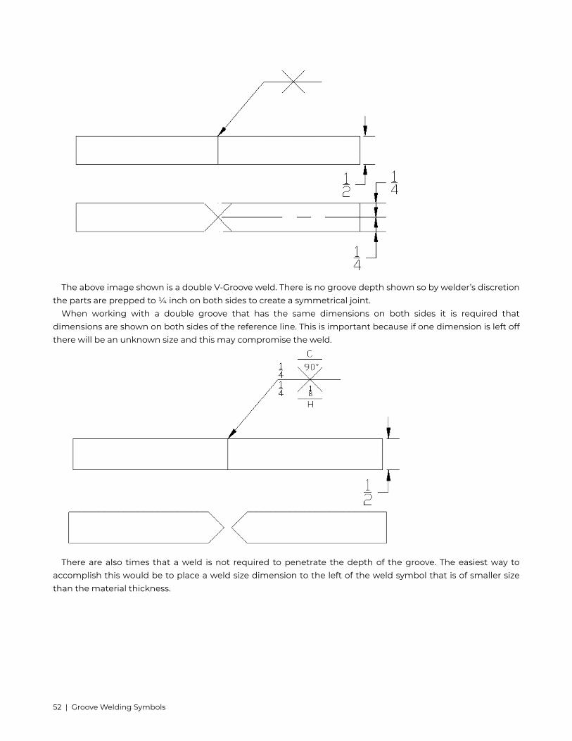
The above image shown is a double V-Groove weld. There is no groove depth shown so by welder’s discretionthe parts are prepped to ¼ inch on both sides to create a symmetrical joint.
When working with a double groove that has the same dimensions on both sides it is required thatdimensions are shown on both sides of the reference line. This is important because if one dimension is left offthere will be an unknown size and this may compromise the weld.
There are also times that a weld is not required to penetrate the depth of the groove. The easiest way toaccomplish this would be to place a weld size dimension to the left of the weld symbol that is of smaller sizethan the material thickness.
52 | Groove Welding Symbols
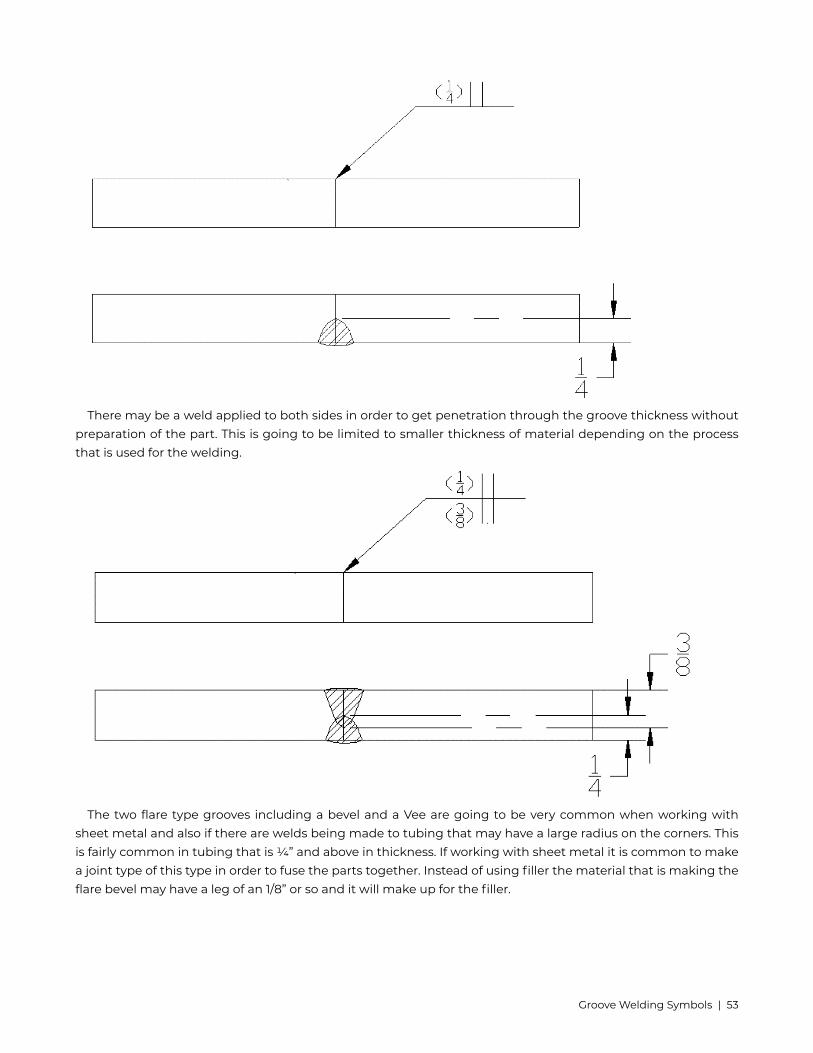
There may be a weld applied to both sides in order to get penetration through the groove thickness withoutpreparation of the part. This is going to be limited to smaller thickness of material depending on the processthat is used for the welding.
The two flare type grooves including a bevel and a Vee are going to be very common when working withsheet metal and also if there are welds being made to tubing that may have a large radius on the corners. Thisis fairly common in tubing that is ¼” and above in thickness. If working with sheet metal it is common to makea joint type of this type in order to fuse the parts together. Instead of using filler the material that is making theflare bevel may have a leg of an 1/8” or so and it will make up for the filler.
Groove Welding Symbols | 53

When using either of these symbols it is important to know the difference between the preparation of groovedepth as well as the weld size. Similar to a regular bevel or vee the preparation of groove depth is going to be tothe left of the weld symbol and also to the left of the weld size which will be shown in parenthesis. Length canbe added in a dimension to the right of the weld symbol.
Back, Backing weld, Surfacing weldA back or backing symbol is the same for both, you must look in the tail for further information to
distinguish between them.A back weld is when a weld is made in the groove of a joint and followed by a weld applied to the root
side. This is most commonly used to insure complete penetration on CJP grooves. The Back weld is usuallyapplied after the root has been ground or gouged out to make sure that the weld is made to sufficient material.When trying to remember the difference between a back and backing weld, you must always go back in orderto do a back weld.
A backing weld is made on the root side of a groove in order to ensure that the weld that is going to bemade in the groove does not melt through the backside. This may also help ensure CJP.
54 | Groove Welding Symbols

Below is a representation of a backing weld.
Below is a representation of a back weld.
There are times where the tail will be omitted from the drawing and in the tail there will be a note thatmay say which order the welds are to be made. It may be as simple as “other side weld made first” or mayinclude true terms such as “other side bevel groove welded before back weld on arrow side.”
Surfacing weldsSurfacing welds are made by single or multiple passes to parts for a variety of reasons. These may include
buildup of worn material, hard facing a part, or increasing part dimensions. This symbol may be on the arrowside of a joint only. It is important that the arrow points specifically where the surfacing shall be added.
These welds may include a thickness of weld which will be located to the left of the weld symbol and may alsoshow a length to the right of the symbol. With this type of weld it will more than likely have a detail view withdimensions for the welding.
Groove Welding Symbols | 55

When a surfacing weld may need multiple layers this may be shown in a note on the blueprint or it could alsobe determined by the reference lines. There are times where there may be more than one reference line whichgives it an order of operation. For example if you think of a backing weld this would be listed on the referenceline which is closest to the arrow, the groove weld would be placed on the second reference line.
To show this in surfacing welds it may ask for a specific size for the first layer of buildup and then adifferent size for the second or subsequent layers. If there is a change in direction this may be shown in the tailof a multi reference welding symbol.
A surfacing weld will run the entire length of the part unless there is a dimension, note, or otherdesignating it is not full. This also plays a part when welding a shaft or other round object. With a round objectrather than a longitudinal (long dimension) or lateral (short dimension) of the part you may see axial (the lengthof the shaft) or circumferential (around the shaft.) When a weld will be done to a shaft or other round part thismust be called out or an incorrect procedure may be applied.
56 | Groove Welding Symbols

Groove Welding Symbols | 57

8. Plug Weld symbols
Plug welds are a round weld that is made inside of an existing hole most commonly in one piece of metal,welding that piece to another member. The plug weld symbol is a rectangle with a diameter symbol placed tothe left of the symbol as well as the number associated with that diameter.
Some drawings will not indicate the hole in the print so the use of dimensions come in to play when locatingwhere a plug weld will be executed. The location will be indicated by a centerline through the part.
Above is indicating a ½” plug weld offset 1” from the edge to the center of the weld.Some plug welds may include a countersink of the hole of the plug weld. This is called the included angle of
countersink. This angle is shown below the rectangle of the symbol itself or if the plug weld is to be on the otherside it will be placed above the weld symbol. When figuring sizing of the hole remember that the diameter willbe the narrow of the hole at the base of the weld.
58 | Plug Weld symbols

Without a countersink included it will be necessary to follow shop standards and procedures to dictate whatthis needs to be, if any angle. Most shops have a procedure in place for tasks that will be done often. If it isneeded it may be listed on a welding procedure for the plug welds that are being completed.
If a number of plug welds are needed there will be yet another element added to the symbol. This will be anumber that is surrounded in parentheses, such as (6) for example.
When applying a plug weld it is important to know the depth of fill that is required. If the plug weldshould fill the hole provided then the symbol will be left empty. This means there will be no dimension insideof the rectangle. If the hole should be filled only so much then this will be placed inside of the rectangle. Thisdimension will be in a fraction and indicates the amount in inches the hole will be filled, not the necessarilyhow much the hole will be filled.
Plug Weld symbols | 59

Another element that can be added to this weld symbol may be the pitch (spacing) for multiple welds. This islocated to the right of the symbol and is a number representing the center to center spacing for weld location.
Plug welds may have a contour symbol which will be added below the symbol or countersink angle if onthe arrow side and above if it is on the other side of the reference line. There are many types of contours andfinishing designations, these are covered in supplementary welding symbols.
60 | Plug Weld symbols

This symbol represents:Plug WeldArrow Side½ inch in diameter1/8” amount of fill45 degree included angle of countersinkFlat contourFinished by MachiningSlot Weld Symbol
The slot weld symbol is the same that is used for plug welds. The symbol will not show a diametersymbol before the size however. The size of the weld will be the slot width instead. This is shown to the left ofthe symbol just as it is shown in plug welds.
1/2” width slot weldThe length of the slot weld will be presented to the right of the symbol. This may also include a pitch showing
the center to center spacing of the slot welds. If there is a pitch there will be a number of slot welds provided inparenthesis under the symbol on the arrow side or above the symbol on an other side weld.
Plug Weld symbols | 61

The drawing must show the orientation of the slot welds as to not confuse direction along the part. Theabove image shows the slots with a vertical orientation to the part versus a horizontal layout as shown below.
A slot weld can include any number of elements, these are very similar to the plug weld symbol that was justexplained.
These can include:Arrow or other sideSize (width)Length of slotPitchDepth of fillNumber of welds requiredContourFinish
Make no mistake on the fill of a plug or slot weld fill. There is a possibility of having a fillet weld inside ofa hole versus actually filling the hole for a plug weld. This could also be mistakenly done on a slot weld.
62 | Plug Weld symbols

Plug and Slot QuizWrite down all information regarding the below Welding Symbols.
Plug Weld symbols | 63

64 | Plug Weld symbols

9. Spot, Seam, Stud Welding Symbols
Spot WeldThe spot weld symbol is simply a circle that may be placed above, below, or centered on the reference line.
When the symbol is centered on the reference line this indicates that there is no side significance. When thereis no side significance this can commonly be applied using a resistance spot welder which is used widely insheet metal work.
A spot weld is simple a weld applied to the surface of one member that has enough heat input to melt intothe material that is creating the faying surface. This is done with no prior preparation to the parts.
An example of arrow side spot weld and a no side significance resistance spot weld below.
The size of a spot weld is going to be placed to the left side of the welding symbol. This number indicates thediameter of said spot weld at the faying surface. The faying surface is where two parts are placed on top of eachother at close proximity.
The number of spot welds required will be added in parenthesis above or below the symbol depending onlocation of the symbol. If it is centered on the reference line the placement of required welds could be placedabove or below the symbol.
Spot, Seam, Stud Welding Symbols | 65

Pitch can be added to the spot weld symbol as well. This will be presented to the right of the symbol.
When a pitch is used this is stating that this will be continued across the full length of the part. For exampleif the part is 20 inches long you would be applying welds every 2 inches using the above symbol for the lengthof that 20 inch part. If the spot welding will not be covering the full length of the part this will need to be shownwith dimension lines on the print in order to communicate this information properly.
Full length call out:
66 | Spot, Seam, Stud Welding Symbols

Partial length of part:There are times when instead of using a diameter dimension the call out will be for shear strength. This
is how resistant something is to shearing. This can be called out in pound-force (lbf) or if the blueprint is inmetric it would call for Newton’s (N).
This calls for a spot weld with 500 pound-forceshear strength.
(500 lbf specifies that the part will be able to resist shearing to a minimum of 500 lbf.It may be specified what process will be used to achieve the weld and this will be put into the tail.
Common processes for this would be resistance spot welding, and gas tungsten arc welding. The reasoningbehind these are there could be no added filler used with the weld so there will be less of a chance for lack offusion. Many other processes may be used as long as the effects of the weld are known and still acceptable forthe outcome of the weld.
A contour may be added to the spot symbol in order to ensure that the surface is flush as if no weld has takenplace. This will go into further detail in supplementary welding symbols.
Spot, Seam, Stud Welding Symbols | 67

For an example below is an arrow side weld with a flush contour by grinding.
Seam WeldThe seam weld uses a similar process as a spot weld but in an elongated fashion. There is no preparation
like a plug or slot weld, rather the weld projects through the top surface and melts into the other member bymeans of heat input. The symbol is similar but it carries two parallel lines through it.
An example of a seam weld:
68 | Spot, Seam, Stud Welding Symbols
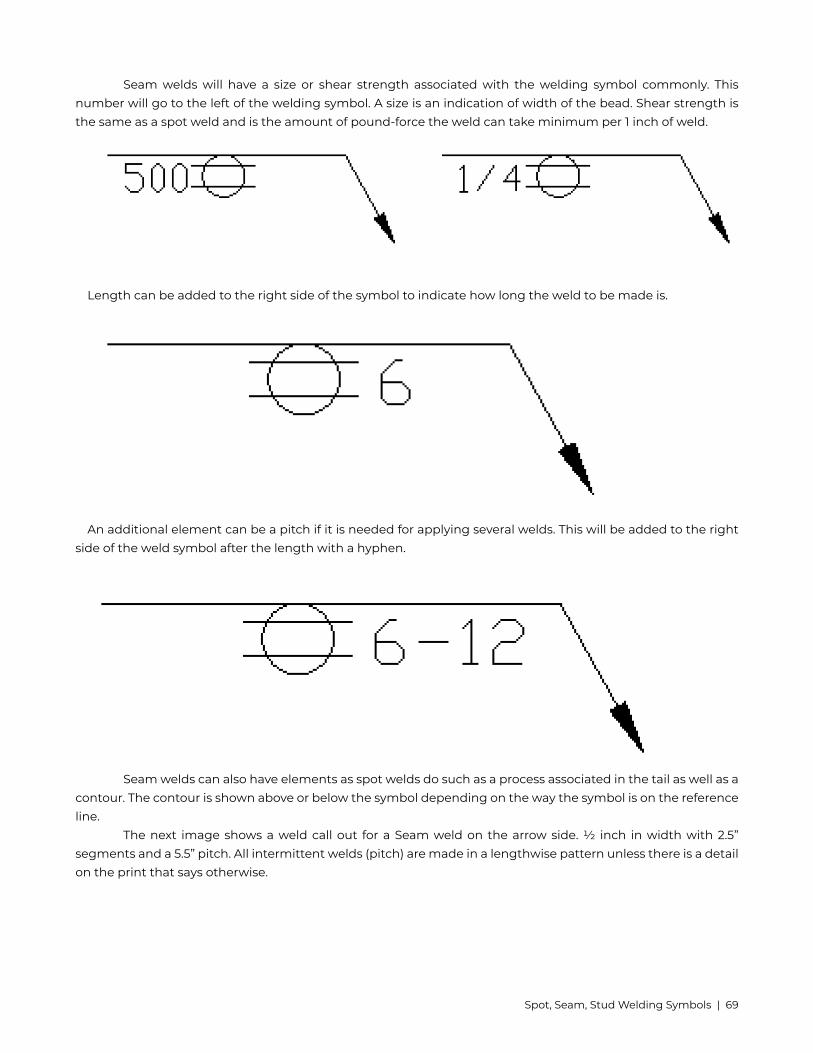
Seam welds will have a size or shear strength associated with the welding symbol commonly. Thisnumber will go to the left of the welding symbol. A size is an indication of width of the bead. Shear strength isthe same as a spot weld and is the amount of pound-force the weld can take minimum per 1 inch of weld.
Length can be added to the right side of the symbol to indicate how long the weld to be made is.
An additional element can be a pitch if it is needed for applying several welds. This will be added to the rightside of the weld symbol after the length with a hyphen.
Seam welds can also have elements as spot welds do such as a process associated in the tail as well as acontour. The contour is shown above or below the symbol depending on the way the symbol is on the referenceline.
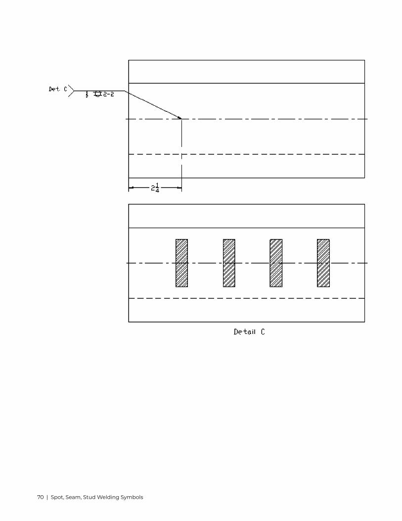
The next image shows a weld call out for a Seam weld on the arrow side. ½ inch in width with 2.5”segments and a 5.5” pitch. All intermittent welds (pitch) are made in a lengthwise pattern unless there is a detailon the print that says otherwise.
Spot, Seam, Stud Welding Symbols | 69
70 | Spot, Seam, Stud Welding Symbols
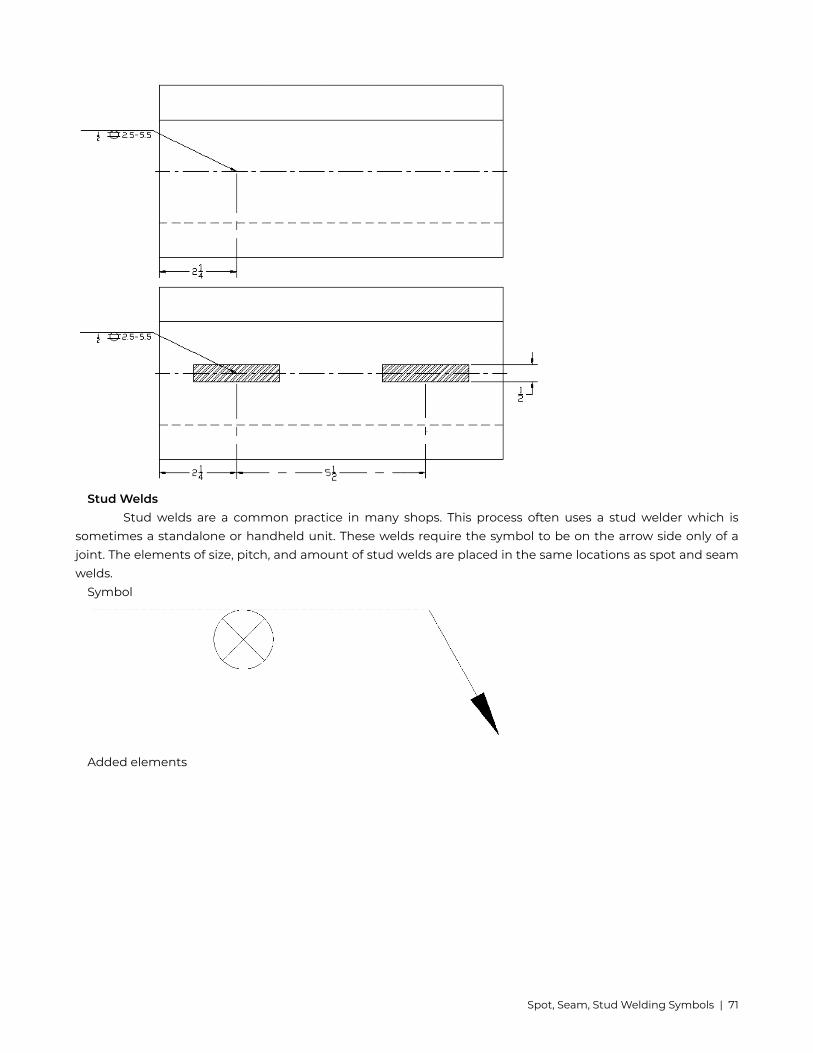
Stud WeldsStud welds are a common practice in many shops. This process often uses a stud welder which is
sometimes a standalone or handheld unit. These welds require the symbol to be on the arrow side only of ajoint. The elements of size, pitch, and amount of stud welds are placed in the same locations as spot and seamwelds.
Symbol
Added elements
Spot, Seam, Stud Welding Symbols | 71

The above weld is calling for six ½” diameter stud welds placed at a 4” center to center spacing.Studs come in all sorts of sizes, shapes, and varieties. For example there are studs for concrete anchors,
threaded bolt patterns, tapped studs to use as a bolt, insulation hangers, and even hard faced studs to replacehard facing a part.
Spot, Stud, Seam QuizIn the space below draw a symbol for the following:3/16” spot weld on the arrow side, ground flush, a pitch of 2”, and 8 total welds.1” Stud welds on the arrow side, 2” pitch, 20 total studs.Resistance seam weld with no side significance, 8” pitch, 16” length.1/4” stud welds on the arrow side with a pitch of 2”. If the part is 20” long and the first stud is placed 1” from
the edge how many studs are required?
72 | Spot, Seam, Stud Welding Symbols

10. Edge Weld Symbols
Edge weld symbols are most commonly associated with sheet metal or “gauge” material. This gauge is asystem used in order to call out sheet metal similar to that of electricians and wire. This chart can range fromthe largest gauge of carbon steel at #7 which is a decimal of .1793” all the way to the smallest which is #28 at adecimal of .0149.” This system is much simpler than using a fraction for how small these numbers are. It is alsoimportant to know that there are specific charts for carbon steel, aluminum, stainless steel, brass, copper, andgalvanized steel.
The edge weld may include a weld size which will be shown to the left of the weld symbol. The weld size is ameasurement of depth of fusion, not necessarily the width of the weld. This does not mean these dimensionscouldn’t be the same. If there is not a size specified it will be up to the welder’s discretion.
Edge Weld Symbols | 73

Single sided edge welds are used on edge joints, flanged butt joints, and flanged corner joints. If there is adouble edge weld it will be used only with a flat edge joint. This is shown below:
For edge welds a length can be associated with the symbol and it will be shown to the right of the weldsymbol. If there is not a dimension shown to the right it will be full length of the part. There may be otherindicators shown on a print of what weld length is required by using hatching or notes. Below shows an edgesymbol with an 8” length as well as a detail view of a part to show specifically where two 2” welds will be located.
74 | Edge Weld Symbols

In chapter 3 Fillet Welds there was a section on length and pitch. An edge weld can also be welded inthis same manner. This will be shown to the right with length followed by a hyphen and then the pitch. This canalso include a chain intermittent edge weld for an edge joint. This will be more common with thicker materialwhen it is a lengthy weld.
Edge Weld Symbols | 75

There may be a staggered intermittent edge weld as well. This is shown the same as a chain intermittent edgeweld but the symbols will be offset.
When the location for these welds are not obvious it will be called out on the blueprint. This may come froma note or detail drawing or even by using extension lines.
76 | Edge Weld Symbols

Some edge welds will be including more than 2 members. In this case there will be only one arrow that pointsat the joint but encompasses all of the members. This will be more common with sheet metal.
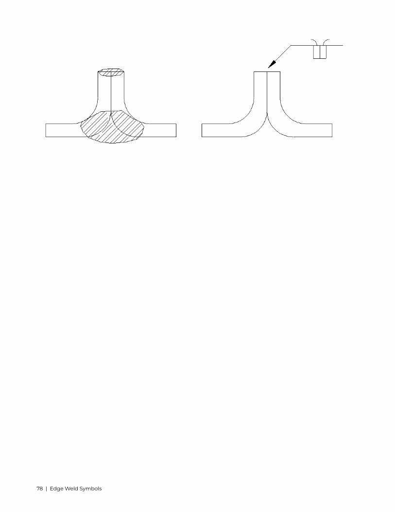
With an edge joint on a flanged butt joint or corner joint there could be the possibility of melt through.This is talked more in detail in Supplementary Symbols. When this symbol shows it is an indicator that the weldis by design supposed to burn through the back side of the material. This is quite common with sheet metalwhen the worry of burning a hole or something of the sort is a concern.
Melt through may be left as simple as the symbol or it may include a size. This is shown to the left of thesymbol and indicates how much penetration past the weld joint is required. This is referred to as melt-through.
Another type of weld that is commonly seen with an edge weld is a flare bevel or flare v groove. This isbecause the opposite side of the edge is exactly that type of configuration. This may be called for on materialsthat adequate melt through cannot be achieved or an engineer’s request.
Edge Weld Symbols | 77
78 | Edge Weld Symbols

11. Process and Method
Process and Method | 79

Type Process Designation
Arc Welding
Shielded Metal Arc Welding SMAW
Gas Tungsten Arc Welding GTAW
Gas Metal Arc Welding GMAW
Gas Metal Arc Welding Pulsed GMAW-P
Flux Cored Arc Welding Gas Shielded FCAW-G
Flux Cored Arc Welding Self Shielded FCAW-S
Submerged Arc Welding SAW
Plasma Arc Welding PAW
Electro slag Welding ESW
Electro gas Welding EGW
Gas Welding
Oxyacetylene Welding OAW
Brazing
Torch Brazing TB
Furnace Brazing FB
Induction Brazing IB
Cutting
Oxyacetylene Cutting OFC-A
Air Carbon Arc Cutting CAC-A
Plasma Arc Cutting PAC
Arc Cutting AC
Gas Metal Arc Cutting GMAC
Oxygen Cutting OC
Gas Tungsten Arc Cutting GTAC
80 | Process and Method

There are a lot of processes in the welding industry, in order to streamline the call out of these there are letterdesignations for them. This designation is a letter callout and it commonly follows the first letter of the processname. For example Flux Cored Arc Welding is FCAW.
When a process is specified it will be located in the tail of the welding symbol. This can be added toseveral other components on the welding symbol.
MethodThe method by which the weld is applied may also be listed in the welding symbol. This will often be seen after
a process with a hyphen. There are four different methods of applying a weld and the designation is the first twoletters from the first word for the first three. Number Four comes from the first two letters of the hyphenatedwords. These methods vary depending on process and may not be applicable to all welding processes.
Automatic WeldingAUManual WeldingMAMechanized WeldingMESemi-Automatic WeldingSA
The above image shows a Gas Tungsten Arc Weld process using a Manual method.Also included in the tail could be a reference to a drawing number, a welding procedure (commonly
called out as WP,) filler material, or any other pertinent information that may need to be communicated to thewelder or fitter.
Examples of this information:Drawing Number 5DWG5Welding Procedure 6WP-6Gas Tungsten Arc Welding – Manual ER70-s FillerGTAW-MAER70-s
Process and Method | 81

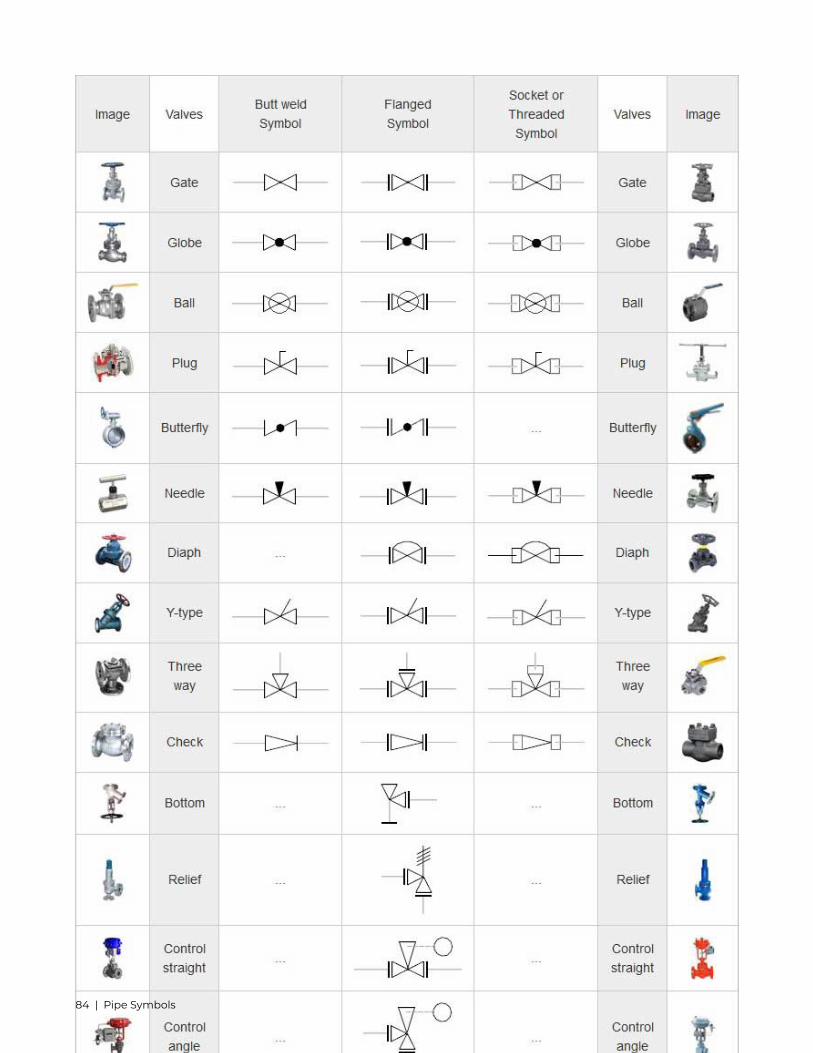
12. Pipe Symbols
Pipe Drawings are much different from specific weld symbols but they do have a similar relationship from partto symbol. Some individuals will not see these in their line of work but it is important to be aware of them.
As with weld symbols, pipe symbols are a reflection of what that part would look like in theory. For example ifa 90 degree elbow is to be placed in service the drawing will reflect a 90 degree angle. There may be multiplesymbols for one fitting or part depending on the fashion it is to be installed (Butt weld, Socket Weld, Threaded.)
Below is a breakdown of almost every type of fitting and connection.
Coordination System Symbols for Isometrics
82 | Pipe Symbols

Pipe Symbols | 83
84 | Pipe Symbols

Pipe Symbols | 85

Note: Symbols are shown in black lines. Lighter lines show connected pipe, and are not parts of the symbols.Provided by:
www.wermac.org.
86 | Pipe Symbols
13. Pipe Drawings
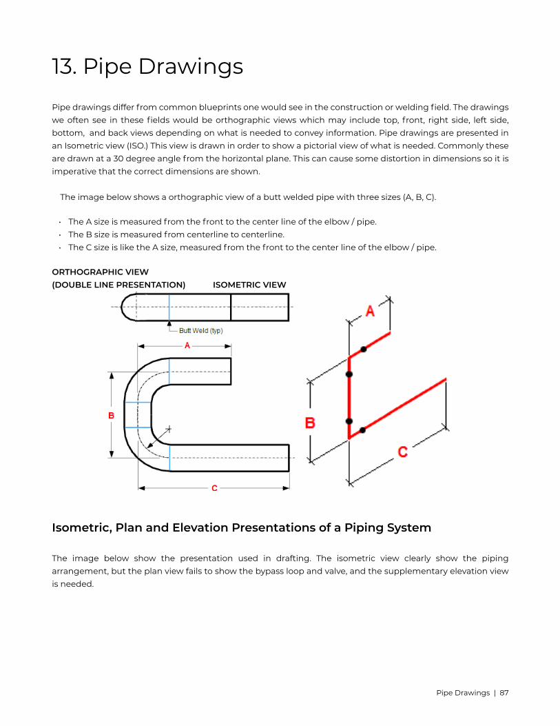
Pipe drawings differ from common blueprints one would see in the construction or welding field. The drawingswe often see in these fields would be orthographic views which may include top, front, right side, left side,bottom, and back views depending on what is needed to convey information. Pipe drawings are presented inan Isometric view (ISO.) This view is drawn in order to show a pictorial view of what is needed. Commonly theseare drawn at a 30 degree angle from the horizontal plane. This can cause some distortion in dimensions so it isimperative that the correct dimensions are shown.
The image below shows a orthographic view of a butt welded pipe with three sizes (A, B, C).
• The A size is measured from the front to the center line of the elbow / pipe.• The B size is measured from centerline to centerline.• The C size is like the A size, measured from the front to the center line of the elbow / pipe.
ORTHOGRAPHIC VIEW(DOUBLE LINE PRESENTATION) ISOMETRIC VIEW
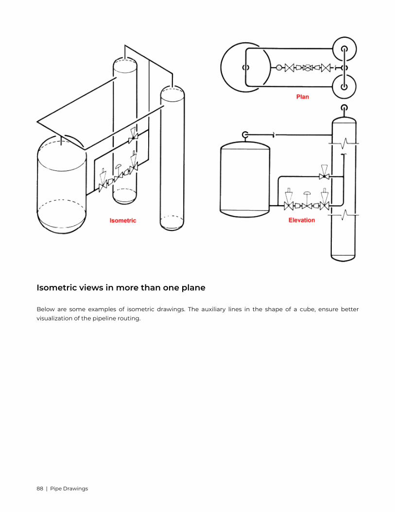
Isometric, Plan and Elevation Presentations of a Piping System
The image below show the presentation used in drafting. The isometric view clearly show the pipingarrangement, but the plan view fails to show the bypass loop and valve, and the supplementary elevation viewis needed.
Pipe Drawings | 87
Isometric views in more than one plane
Below are some examples of isometric drawings. The auxiliary lines in the shape of a cube, ensure bettervisualization of the pipeline routing.
88 | Pipe Drawings

Figure 1 shows a pipeline which runs through three planes. The pipe line begins and ends with a flange.Routing starting point X
• pipe runs to the east• pipe runs up• pipe runs to the north• pipe runs to the west• pipe runs down
Pipe Drawings | 89
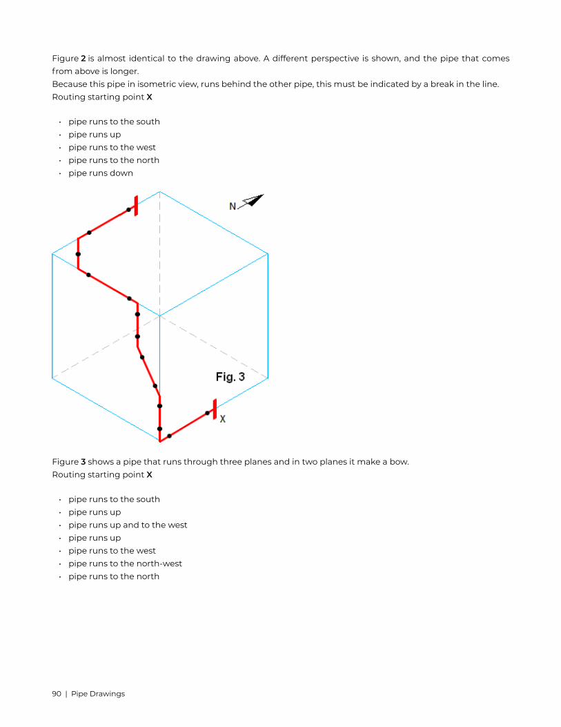
Figure 2 is almost identical to the drawing above. A different perspective is shown, and the pipe that comesfrom above is longer.Because this pipe in isometric view, runs behind the other pipe, this must be indicated by a break in the line.Routing starting point X
• pipe runs to the south• pipe runs up• pipe runs to the west• pipe runs to the north• pipe runs down
Figure 3 shows a pipe that runs through three planes and in two planes it make a bow.Routing starting point X
• pipe runs to the south• pipe runs up• pipe runs up and to the west• pipe runs up• pipe runs to the west• pipe runs to the north-west• pipe runs to the north
90 | Pipe Drawings

Figure 4 shows a pipe that runs through three planes, from one plane to a opposite plane.Routing starting point X
• pipe runs to the south• pipe runs up• pipe runs up and to the north-west• pipe runs to the north
Pipe Drawings | 91