intrinsically porous polymer protects catalytic gold ...opus.bath.ac.uk/39459/3/glucose.pdf ·...
TRANSCRIPT
1
Revsion
8th March 2014
Intrinsically Porous Polymer Protects Catalytic Gold
Particles for Enzymeless Glucose Oxidation
Yuanyang Rong 1, Richard Malpass-Evans 2, Mariolino Carta 3, Neil B. McKeown 3,
Gary A. Attard 2, and Frank Marken *1
1 Department of Chemistry, University of Bath, Claverton Down, Bath BA2 7AY, UK 2 School of Chemistry, Cardiff University, Cardiff CF10 3AT, UK
3 School of Chemistry, University of Edinburgh, West Mains Road, Edinburgh,
EH9 3JJ, UK
To be submitted to Electroanalysis
Proofs to F. Marken ([email protected])
2
Abstract
The enzymeless glucose oxidation process readily occurs on nano-gold electrocatalyst at
pH 7, but it is highly susceptible to poisoning (competitive binding), for example from
protein or chloride. Is it shown here that gold nanoparticle catalyst can be protected
against poisoning by a polymer of intrinsic microporosity (PIM-EA-TB with BET surface
area 1027 m2g-1). This PIM material when protonated, achieves a triple catalyst
protection effect by (i) size selective repulsion of larger protein molecules (albumins) and
(ii) membrane ion selection effects, and (iii) membrane ion activity effects. PIM materials
allow “environmental control” to be introduced in electrocatalytic processes.
Keywords: glucose, fuel cell, sensor, microporosity, membrane, electrocatalysis.

3
1. Introduction
New materials in electrochemistry offer opportunities for improved devices and processes
and in the recent years several cases of interesting novel porous solids, e.g. metal-organic
frameworks [1], zeolitic materials [2], or mesoporous films [3], have emerged. In terms
of polymeric materials, there have been many areas of progress including gels [4],
conducting polymers [5], and brushes [6]. The recent development of polymers with
intrinsic microporosity (PIMs) and similar novel materials [7] is particularly interesting
with a range of potential applications in electrochemical technology. Uncharged PIM
materials have been proposed [8] and developed for gas storage [9,10] gas separation
[11,12,13], and as sensor component [14]. The structurally highly rigid and disordered
PIM backbone achieves open packing to generate novel properties due to permanent
microporosity. When charged, these PIM materials introduce ion selectivity,
permselectivity, and further porosity effects which are closely linked to the molecular
structure and functionalization of the backbone. Physicochemical characteristics are
related to those observed for hydrogels [15,16] rather than those associated with
polymeric systems. To date, potential applications are based on PIM-gas interaction, but
our recent publication [17] has demonstrated benefits of PIM-electrolyte interactions and
potential applications in solution phase electrocatalysis.
The preparation of amine-containing PIMs based on a polymerisation reaction involving
the formation of Tröger’s base (TB) was reported [18]. Thus, 2,6(7)-diamino-9,10-
4
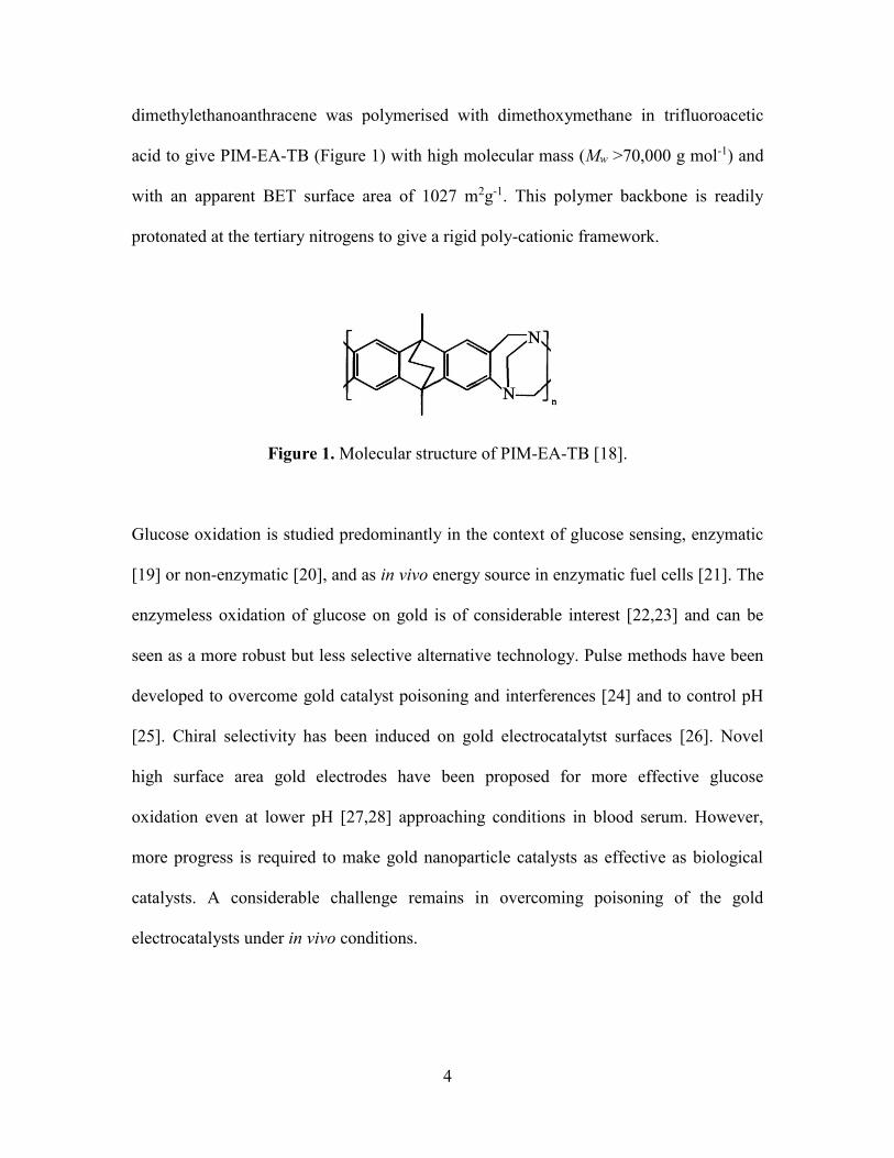
dimethylethanoanthracene was polymerised with dimethoxymethane in trifluoroacetic
acid to give PIM-EA-TB (Figure 1) with high molecular mass (Mw >70,000 g mol-1) and
with an apparent BET surface area of 1027 m2g-1. This polymer backbone is readily
protonated at the tertiary nitrogens to give a rigid poly-cationic framework.
Figure 1. Molecular structure of PIM-EA-TB [18].
Glucose oxidation is studied predominantly in the context of glucose sensing, enzymatic
[19] or non-enzymatic [20], and as in vivo energy source in enzymatic fuel cells [21]. The
enzymeless oxidation of glucose on gold is of considerable interest [22,23] and can be
seen as a more robust but less selective alternative technology. Pulse methods have been
developed to overcome gold catalyst poisoning and interferences [24] and to control pH
[25]. Chiral selectivity has been induced on gold electrocatalytst surfaces [26]. Novel
high surface area gold electrodes have been proposed for more effective glucose
oxidation even at lower pH [27,28] approaching conditions in blood serum. However,
more progress is required to make gold nanoparticle catalysts as effective as biological
catalysts. A considerable challenge remains in overcoming poisoning of the gold
electrocatalysts under in vivo conditions.

5
It is shown here that the properties of PIM polymer membranes spin-coated over the gold
nanoparticle catalyst can help protecting the catalyst from poisoning. The effect of the
PIM membrane is studied (i) on the gold nanoparticle catalyst formation, (ii) on the
electrocatalytic glucose oxidation mechanism, (iii) on the effect of protein on gold
catalyst poisoning, and (iv) on the effect of chloride on gold catalyst poisoning in
phosphate buffer at pH 7. PIM membranes are proposed as a versatile new class of
materials for electrochemistry in particular for controlling the reaction environment in
electrocatalytic processes.
2. Experimental
2.1. Chemical Reagents
Potassium gold(III) tetrachloride , D-(+)-glucose, albumin from bovine serum, sodium
chloride, phosphoric acid (85%), potassium chloride, sulphuric acid (95%-98%), and
sodium hydroxide were purchased from Aldrich or Fisher Scientific and used without
further purification. PIM-EA-TB was prepared following a literature recipe [18].
Solutions were prepared with filtered and deionized water of resistivity 18.2 MΩ cm
from a Thermo Scientific water purification system (ELGA).
2.2. Instrumentation
A potentiostat system (IVIUM Compactstat) was employed with a Pt wire counter
electrode and a KCl-saturated calomel reference (SCE, Radiometer, Copenhagen). The
working electrode was prepared from ITO coated glass (tin-doped indium oxide films
sputter-coated onto glass, active area 10 mm × 10 mm, resistivity ca. 15 Ω per square)

6
obtained from Image Optics Components Ltd (Basildon, Essex, UK). ITO electrodes
were rinsed with ethanol and water, heat-treated in a tube furnace (Elite Thermal System
Ltd) for 30 minutes at 500 °C, and then re-equilibrated to ambient conditions. All
experiments were conducted at a temperature of 293±2K.
2.3. Gold Nanoparticle Deposition Method
A gold(III) solution was prepared by dissolving 1 mM KAuCl4 in 0.1 M KCl addition of
sulphuric acid to pH 2. Electrodeposition was performed in chronoamperometry mode.
ITO electrodes were pre-treated at 1 V vs. SCE for 10 s followed by plating at -0.2 V vs.
SCE for 200 s, rinsing with water, and drying under ambient conditions.
2.4. Polymer with Intrinsic Microporosity Coating Method
Initially, a solution of 1 mg cm-3 PIM-EA-TB in chloroform was applied directly by
dipping the electrode followed by drying under ambient conditions. Improved coatings
were obtained by spin-coating (Laurell WS-650Mz-23NPP, 1500 rpm for 30 seconds).

7
3. Results and Discussion
3.1. Electrodeposition of Catalytic Gold Nanoparticles onto Tin-Doped Indium Oxide
(ITO) Substrates
The gold electrodeposition approach was selected based on an aqueous solution of 1 mM
KAuCl4 in 0.1 M KCl at pH 2 (acidified with H2SO4). The deposition experiments were
conducted at -0.2 V vs. SCE for 200 s (if not stated otherwise) to form a uniform deposit
of gold nanoparticles on the ITO substrate (see Figure 2A,B). Particles are typically 100
nm to 200 nm in diameter and well distributed over the electrode surface.
In cyclic voltammetry experiments these gold deposits immersed in 0.1 M phosphate
buffer at pH 7 give stable voltammetric responses (see Figure 3A) with gold oxidation
(see peak Iox at 0.80 V vs. SCE) and gold back-reduction (see peak Ired at 0.55 V vs. SCE)
indicative of an active gold surface.

8
Figure 2. Scanning electron microscopy images for (A) gold nanoparticles grown on ITO
for 200 s, (B) higher magnification image of gold nanoparticles.
The gold electrodeposition was repeated in the presence of a PIM film spin-coated onto
the ITO surface (ca. 500 nm thickness). The same type of gold nanoparticle deposit was
formed (confirmed by voltammetry and electrocatalysis experiments, vide infra). But
unfortunately these films were unstable and easily peeled off the surface together with the

9
PIM film. Better quality films were obtained by first electroplating gold nanoparticles
onto ITO and then coating with PIM. Drop-coating PIM resulted in film imperfection, but
spin-coating a solution 1 mg cm-3 PIM in chloroform at 1500 rpm (see experimental)
resulted in high quality film coatings.
3.2. Glucose Oxidation on Catalytic Gold Nanoparticles on Tin-Doped Indium Oxide
(ITO) Substrates
The oxidation of glucose on gold nanoparticles immersed in phosphate buffer pH 7 has
been reported previously and a typical anodic current peak is seen at 0.3 V vs. SCE (see
Figure 3). As expected for a surface-catalytic kinetically controlled current response, this
peak is not affected by scan rate (see Figure 3B) but strongly affected by the gold
nanoparticle catalyst deposition time (see Figure 3C, peak II, note that this peak is
observed most clearly during the potential sweep towards negative potentials). A plot of
the effect of the gold nanoparticle deposition time on the glucose oxidation peak current
is shown in Figure 3D. An improvement in the catalytic signal is seen up to
approximately 400 s electrodeposition.

10
Figure 3. (A) Cyclic voltammograms (first and second cycle, scan rate 5 mVs-1, start
point 0.0 V vs. SCE) for gold nanoparticles on ITO immersed in 0.1 M phosphate buffer
pH 7. (B) As before, but with 8 mM glucose and scan rate (i) 5, (ii) 10, (iii) 20, (iv) 50,
(v) 100 mVs-1. (C) As before, but with 8 mM glucose, scan rate 5 mVs-1, and (i) 100 s,
(ii) 200 s, (iii) 300 s, (iv) 600 s gold nanoparticle deposition time. (D) Plot of the glucose
oxidation peak versus gold nanoparticle deposition time.
11
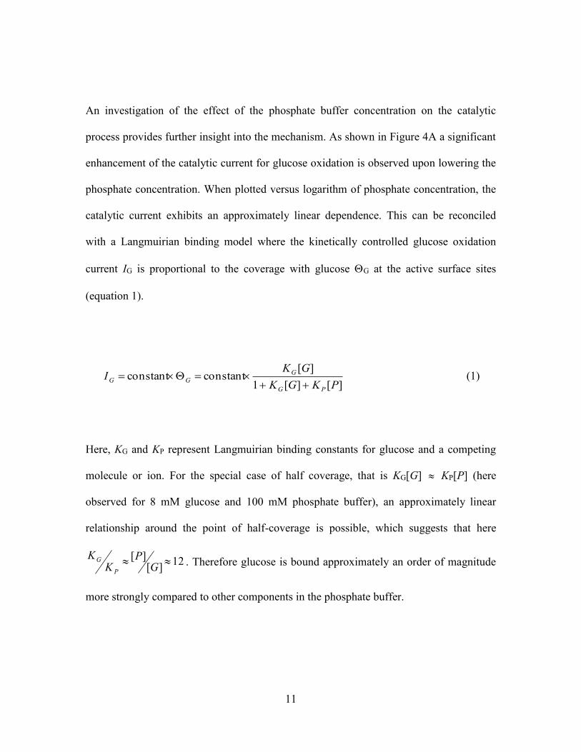
An investigation of the effect of the phosphate buffer concentration on the catalytic
process provides further insight into the mechanism. As shown in Figure 4A a significant
enhancement of the catalytic current for glucose oxidation is observed upon lowering the
phosphate concentration. When plotted versus logarithm of phosphate concentration, the
catalytic current exhibits an approximately linear dependence. This can be reconciled
with a Langmuirian binding model where the kinetically controlled glucose oxidation
current IG is proportional to the coverage with glucose G at the active surface sites
(equation 1).
][][1
][constantconstant
PKGK
GKI
PG
G
GG
(1)
Here, KG and KP represent Langmuirian binding constants for glucose and a competing
molecule or ion. For the special case of half coverage, that is KG[G] KP[P] (here
observed for 8 mM glucose and 100 mM phosphate buffer), an approximately linear
relationship around the point of half-coverage is possible, which suggests that here
12][
][
GP
KK
P
G . Therefore glucose is bound approximately an order of magnitude
more strongly compared to other components in the phosphate buffer.

12
Figure 4. (A) Cyclic voltammograms (scan rate 5 mVs-1, start point 0.0 V vs. SCE) for
the oxidation of 8 mM glucose at gold nanoparticles on ITO immersed in (i) 10, (ii) 100,
(iii) 1000 mM phosphate buffer pH 7. (B) Plot of the peak current versus logarithm of
phosphate buffer concentration.
Next, the effect of glucose concentration is investigated. Figure 5 shows data for gold
nanoparticle catalyst in 0.1 M phosphate buffer pH 7 for different glucose concentrations.
At low glucose levels an approximately linear increase in glucose oxidation current is
observed with plateauing at glucose concentration higher than 12 mM. This observation
is in agreement with the Langmuirian binding model introduced above. The binding
constant can be estimated (here from the point of third coverage, where
3
1
][][1
][
PKGK
GK
PG
G
G with KG[G] KP[P]) as KG 200 mol-1 dm3.

13
Figure 5. (A) Cyclic voltmmograms (scan rate 5 mVs-1, start point 0.0 V vs. SCE) for the
oxidation of (i) 2, (ii) 4, (iii) 8, (iv) 14 mM glucose at gold nanoparticles on ITO
immersed in 0.1 M phosphate buffer pH 7. (B) Plot of the peak current versus glucose
concentration.
3.3. Suppressing Gold Nanoparticle Catalyst Poisoning with Polymer of Intrinsic
Microporosity (PIM) Coating
Phosphate has been shown to compete with glucose for the active catalyst surface sites
and many other molecules and ions potentially interfere or poison the catalyst surface. In

14
order to explore poisoning and the remediating effects of a porous PIM-EA-TB polymer
film two cases are studied: (i) bovine serum albumin and (ii) chloride.
The coating of the polymer of intrinsic microporosity (PIM) PIM-EA-TB is applied by
spin-coating to give approximately 500 nm thick films. This type of film has recently
been shown to allow small ions and molecules such as formic acid to pass with
electrocatalysts working just as well with or without this coating (demonstrated for
formic acid oxidation on palladium [17]). Here the PIM coating is shown to not
detrimentally affect the glucose oxidation (see Figure 6A) with clear oxidation peaks
detected at 0.3 V vs. SCE. The plot of the peak current versus glucose concentration has
an extended range into higher glucose concentrations (see Figure 6B). indicative of less
competition to phosphate buffer (the activity of the phosphate buffer is believed to be
lower in the PIM environment).
15
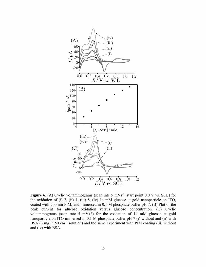
Figure 6. (A) Cyclic voltammograms (scan rate 5 mVs-1, start point 0.0 V vs. SCE) for
the oxidation of (i) 2, (ii) 4, (iii) 8, (iv) 14 mM glucose at gold nanoparticle on ITO,
coated with 500 nm PIM, and immersed in 0.1 M phosphate buffer pH 7. (B) Plot of the
peak current for glucose oxidation versus glucose concentration. (C) Cyclic
voltammograms (scan rate 5 mVs-1) for the oxidation of 14 mM glucose at gold
nanoparticle on ITO immersed in 0.1 M phosphate buffer pH 7 (i) without and (ii) with
BSA (3 mg in 50 cm-3 solution) and the same experiment with PIM coating (iii) without
and (iv) with BSA.

16
When adding bovine serum albumin (BSA) as a known catalyst poison [29], a dramatic
change is observed in the glucose oxidation current. Figure 6C (i) and (ii) show the
current for glucose oxidation on bare gold nanoparticle catalyst before and after addition
BSA (3 mg in 50 cm3 solution), respectively. The same experiment was repeated with
PIM coating (see Figure 6C (iii) and (iv)) with no detrimental effect of the protein. It is
likely that the PIM coating can repel the protein based on size exclusion.
A further severe poisoning effect on the gold nanoparticle electrocatalyst is induced by
chloride. An addition of 10 mM chloride into 0.1 M phosphate buffer pH 7 almost
completely eliminates the catalytic glucose oxidation (see Figure 7A (i) and (ii)). When
the PIM coating is applied this effect is considerably less dramatic. In Figure 7A (iii) and
(iv) the glucose oxidation for 8 mM glucose in 0.1 M phosphate buffer pH 7 is shown
without and with 10 mM chloride, respectively, and only a 50% drop in current occurs.
Therefore the PIM membrane changes the access of chloride to the catalyst surface (e.g.
by competition of phosphate and chloride for PIM anion sites).

17
Figure 7. (A) Cyclic voltammograms (scan rate 5 mVs-1, start point 0.0 V vs. SCE) for
the oxidation of 8 mM glucose at gold nanoparticles on ITO immersed in 0.1 M
phosphate buffer pH 7 (i) without and (ii) with 10 mM chloride and the same experiment
with PIM coating (iii) without and (iv) with 10 mM chloride. (B) (A) Cyclic
voltammograms (scan rate 5 mVs-1) for the oxidation of 8 mM glucose at gold
nanoparticles on ITO with PIM coating immersed in 0.1 M phosphate buffer pH 7 with
(i) 0, (ii) 2, (iii) 10, (iv) 50, (v) 100 mM chloride. (C) (A) Cyclic voltammograms (scan
rate 5 mVs-1) for the oxidation of 8 mM glucose at gold nanoparticles on ITO with PIM
coating immersed in 0.01 M phosphate buffer pH 7 with (i) 0, (ii) 2, (iii) 10, (iv) 50, (iv)
100 mM chloride. (D) Plot of the peak current for glucose oxidation versus chloride
concentration for 0.1 and 0.01 M phosphate buffer pH 7.
18
These experiments were repeated systematically for a range of chloride concentrations
and for two phosphate buffer concentrations. The plot in Figure 7D shows both the effect
of the lower buffer concentration increasing the glucose oxidation current and the effect
of chloride reducing the catalyst activity. The observed data plot is again consistent with
the model of competitive Langmuirian binding (equation 1). Interestingly, with the PIM
coating the gold nanoparticle electrocatalyst is able to effectively operate even in 20 mM
chloride. Typical blood serum levels of chloride are higher and therefore the
improvement in catalyst performance is still not sufficient. However, the observed
improvement with a thin PIM film coating is promising and future development could
focus on (i) improved PIM materials in terms of molecular structure and pore structure
for controlling access of poisons to the catalyst and (ii) improved design of the
“electrocatalyst PIM environment” to optimise conditions in the reaction zone close to
the active catalyst sites.
4. Conclusion
It has been shown that novel PIM materials such as PIM-EA-TB with extremely high
surface area and ability to be protonated (to be semipermeable towards anions) provide a
new class of electrochemically effective components for application in electrocatalysis,
for example for energy harvesting and sensing. The rigid nature of the PIM polymer
backbone minimises structural fluctuations and leads to a stable pore size for selective
transport of neutral and charged species. When protonated, the PIM-EA-TB film exhibits

19
some degree of anion selectivity with potential benefits in electrocatalytic processes (e.g.
widening the linear range, influencing competitive binding equilibria). Here, the
oxidation of glucose on gold at pH 7 in phosphate buffer is investigated as a first model
case. Three types of effects on the catalyst performance are observed:
(i) The size selection effect of PIM pores allows poisoning from larger proteins
such as bovine serum albumin to be suppressed
(ii) The anion selection effect allows access of chloride to the catalyst surface to
be reduced (in competition to phosphate)
(iii) The change in anion activity in the catalyst reaction zone (e.g. reduced
phosphate binding relative to glucose binding and extended linear range)
In future novel PIM materials could be designed and further improved by molecular
control over pore size, pore shape, pore charge distribution, etc. In contrast to hydrogels,
the novel PIM materials are highly stable and more dense to impose a stronger effect on
the membrane permeability and catalyst environment. Rigidity and the molecular
structure of the PIM polymer backbone play a key role in introducing new functionality
and novel effects.
Acknowledgement
Y.R. thanks the University of Bath for a fee waiver.

20
References
[1] A. Morozan, F. Jaouen, Energy Environm. Sci., 2012, 5, 9269.
[2] Z. H. Dai, H. X. Ju, TRAC-Trends Anal. Chem., 2012, 39, 149.
[3] A. Walcarius, Chem. Soc. Rev., 2013, 42, 4098.
[4] D. M. Lin, J. F. Che, Progress Chem., 2010, 22, 1195.
[5] T. F. Otero, J. G. Martinez, J. Arias-Pardilla, Electrochim. Acta, 2012, 84, 112.
[6] N. Ayres, Polymer Chem., 2010, 1, 769.
[7] Z. H. Xiang, D. P. Cao, J. Mater. Chem. A, 2013, 1, 2691.
[8] P. M. Budd, B. S. Ghanem, S. Makhseed, N. B. McKeown, K. J. Msayib, C. E.
Tattershall, Chem. Commun., 2004, 230.
[9] N. B. McKeown, P. M. Budd, Macromolecules, 2010, 43, 5163.
[10] N. B. McKeown, B. Gahnem, K. J. Msayib, P. M. Budd, C. E. Tattershall, K.
Mahmood, S. Tan, D. Book, H. W. Langmi, A. Walton, Angew. Chem. Int. Ed.,
2006, 45, 1804.
[11] S.V. Adymkanov, Y.P. Yampol'skii, A.M. Polyakov, P.M. Budd, K.J.
Reynolds, N.B. McKeown, K.J. Msayib, Polymer Sci., 2008, 50, 444.
[12] P. M. Budd, N. B. McKeown, B. S. Ghanem, K. J. Msayib, D. Fritsch, L.
Starannikova, N. Belov, O. Sanfirova, Y. P. Yampol'skii, V. Shantarovich,
J. Membrane Sci., 2008, 325, 851.
[13] C. G. Bezzu, M. Carta, A. Tonkins, J.C. Jansen, P. Bernardo, F. Bazzarelli, N. B.
McKeown, Adv. Mater., 2012, 24, 5930.
21
[14] Y. Wang, N.B. McKeown, K.J. Msayib, G.A. Turnbull, I.D.W. Samuel,
Sensors, 2011, 11, 2478.
[15] D. Buenger, F. Topuz, J. Groll, Progress Polymer Sci., 2012, 37, 1678.
[16] A. Guiseppi-Elie, Biomaterials, 2010, 31, 2701.
[17] F. J. Xia, M. Pan, S. C. Mu, R. Malpass-Evans, M. Carta, N. B. McKeown, G.
A. Attard, A. Brew, D. J. Morgan, F. Marken, Electrochim. Acta, 2013, in press.
[18] M. Carta, R. Malpass-Evans, M. Croad, Y. Rogan, J. C. Jansen, P. Bernardo, F.
Bazzarelli, N. B. McKeown, Science, 2013, 339, 303.
[19] M. Arredondo, M. Stoytcheva, R. Zlatev, V. Gochev, Mini-Rev. Medicinal
Chem., 2012, 12, 1301.
[20] G. F. Wang, X. P. He, L. L. Wang, A. X. Gu, Y. Huang, B. Fang, B. Y. Geng,
X. J. Zhang, Microchim. Acta, 2013, 180, 161.
[21] Q. Liu, X. H. Xu, G. L. Ren, W. Wang, Progress Chem., 2006, 18, 1530.
[22] Y. Li, Y. Y. Song, C. Yang, X. H. Xia, Electrochem. Commun., 2007, 9, 981.
[23] Y. G. Zhou, S. Yang, Q. Y. Qian, X. H. Xia, Electrochem. Commun., 2009, 11,
216.
[24] M. Pasta, F. La Mantia, Y. Cui, Electrochem. Commun., 2010, 12, 1407.
[25] L. Rassaei, F. Marken, Anal. Chem., 2010, 82, 7063.
[26] A. Martins, V. Ferreira, A. Queirós, I. Aroso, F. Silva, J. Feliu, Electrochem.
Commun., 2003, 5, 741.
[27] A. Celebanska, A. Lesniewski, M. Paszewski, M. Jonsson-Niedziolka, J.
Niedziolka-Jonsson, M. Opallo, Electrochem. Commun., 2011, 13, 1170.
[28] H. du Toit, M. Di Lorenzo, Sens. Actuators B-Chem., 2014, 192, 725.

22
[29] Y. Chen, K. Flowers, M. Calizo, S.W. Bishnoi, Coll. Surfaces B-Biointerfaces,
2010, 76, 241.