intrinsically safe windobserver anemometer · 3.5 earthing ... 1360-g-026 type iic i.s. anemometer...
TRANSCRIPT

Intrinsically Safe WindObserver Anemometer
User Manual
Doc No. 1360-PS-0001Issue 03
Gill Instruments Ltd recognise all trademarks
Gill Instruments LimitedSaltmarsh Park,67 Gosport Street,Lymington,Hampshire.SO41 9EGUK
Tel: +44 (0) 1590 613500Fax: +44 (0) 1590 613501E-mail: [email protected]: www.gill.co.uk

Gill Instruments Ltd_______________________________________________________________________________________________________
Intrinsically Safe WindObserver Anemometer Page 1 Issue 03Doc. No. 1360-PS-0001 September 2002

Gill Instruments Ltd_______________________________________________________________________________________________________
WARNING:
ENSURE CORRECTSUPPLY VOLTAGEIS SELECTED ONPOWER SUPPLY
BEFOREINSTALLATION
Intrinsically Safe WindObserver Anemometer Page 2 Issue 03Doc. No. 1360-PS-0001 September 2002

Gill Instruments Ltd_______________________________________________________________________________________________________
1. FOREWORD................................................................................................................................................52. PACKING LIST...........................................................................................................................................53. INSTALLATION.........................................................................................................................................6
3.1 Mounting................................................................................................................................................63.2 Alignment...............................................................................................................................................63.3 Sealing....................................................................................................................................................63.4 Corrosion................................................................................................................................................63.5 Earthing..................................................................................................................................................63.6 Cabling....................................................................................................................................................63.7 General....................................................................................................................................................6
4. SYSTEM OPERATION...............................................................................................................................74.1 Wind Measurement ................................................................................................................................7
4.1.1 Measurement Sampling Rates and Averages...................................................................................74.2 System Configuration.............................................................................................................................74.3 Default System Configuration................................................................................................................7
5. CONNECTION TO A PC OR OTHER DEVICE........................................................................................86. USING THE ANEMOMETER WITH A COMPUTER AND YOUR SOFTWARE..................................9
6.1 Digital Serial Output Formats.................................................................................................................96.2 Digital Format Notes............................................................................................................................126.3 Status Code...........................................................................................................................................12
7. ANEMOMETER SOFTWARE COMMANDS.........................................................................................147.1 Configuration Mode.............................................................................................................................147.2 Polled Operation...................................................................................................................................147.3 Output Mode.........................................................................................................................................147.4 Output Units.........................................................................................................................................147.5 Measurement Average..........................................................................................................................147.6 Output String Padding..........................................................................................................................147.7 Baud Rate.............................................................................................................................................157.8 Sample Period.......................................................................................................................................157.9 Parity.....................................................................................................................................................157.10 Vertical Padding.................................................................................................................................157.11 Unit Identification...............................................................................................................................157.12 Diagnostics.........................................................................................................................................15
8. DRAWINGS...............................................................................................................................................161086-G-045 Anemometer Installation Details...........................................................................................171360-G-026 Type IIc I.S. Anemometer Dimensions.................................................................................181360-G-028 I.S. WindObserver II System Diagram Sheet 1 of 2..............................................................191360-G-028 I.S. WindObserver II System Diagram Sheet 2 of 2..............................................................201360-M-039 I.S.Terminal Arrangement.....................................................................................................211360-G-043 I.S. PCI Unit...........................................................................................................................229.1 Specification.........................................................................................................................................23
10. POWER AND COMMUNICATIONS INTERFACE..............................................................................2510.1 PCI......................................................................................................................................................25
10.1.1 External Connections...................................................................................................................2510.1.2 Electrical Power Requirements....................................................................................................2510.1.3 Internal Supply ...........................................................................................................................2510.1.4 External Supply ...........................................................................................................................2510.1.5 RS422 Interface...........................................................................................................................2510.1.6 Cable Requirements.....................................................................................................................2510.1.7 Environmental..............................................................................................................................2610.1.8 Material........................................................................................................................................2610.1.9 EMC.............................................................................................................................................26
APPENDIX 1..................................................................................................................................................27SUMMARY OF ABBREVIATIONS USED IN THIS MANUAL...........................................................27OPTIONAL EXTRAS................................................................................................................................29
Intrinsically Safe WindObserver Anemometer Page 3 Issue 03Doc. No. 1360-PS-0001 September 2002

Gill Instruments Ltd_______________________________________________________________________________________________________
APPENDIX 2..................................................................................................................................................30PRODUCT APPROVALS.........................................................................................................................30
SIRA CERTIFICATION........................................................................................................................30
Intrinsically Safe WindObserver Anemometer Page 4 Issue 03Doc. No. 1360-PS-0001 September 2002

Gill Instruments Ltd_______________________________________________________________________________________________________
1. FOREWORD
This manual refers to the Gill Instruments Ltd Intrinsically Safe WindObserver ultrasonicanemometer. It is an extremely sophisticated instrument and to achieve optimumperformance we recommend that you read the whole of this manual before proceedingfurther with use.
The Solent range is in continuous development and so specifications may be subject tochange without prior notice.
2. PACKING LIST
• Intrinsically Safe 2 axis anemometer• Mounting kit• This manual• Intrinsically Safe Power & Communications Interface• Anemometer Connector 20 way• 3m Anemometer Cable
Intrinsically Safe WindObserver Anemometer Page 5 Issue 03Doc. No. 1360-PS-0001 September 2002

Gill Instruments Ltd_______________________________________________________________________________________________________
3. INSTALLATION
3.1 MountingThe Anemometer should be mounted on a suitable surface as defined in drawing 1086-G-045 shown in Section 8, using the mounting kit supplied and described in the PackingList. The anemometer does not require any adjustment - do not attempt todismantle, or warranty and calibration will be void.
3.2 AlignmentThe anemometer should be set to point North, see drawing 1360-G-026 as shown inSection 8, (or to some other known reference direction). This is facilitated by slots in thebase for the mounting screws, which allow rotation of the anemometer for fine alignment.
3.3 SealingThe connector area at the base of the anemometer should not be directly exposed tomoisture or solvents, as whilst the connectors are sealed when mated, the anemometer isvented to air at the base to avoid pressure build up. Therefore use the gasket providedin the mounting kit.
3.4 CorrosionCareful note should be taken of the possibility of galvanic corrosion by incorrectmounting. It is vital that only stainless steel fixings are used and that the instrument isinsulated from the mounting surface with the rubber gasket. This will ensure that theanemometer will provide long service under extreme conditions.
3.5 EarthingThe system must be earthed in accordance with local or national regulations. Intrinsicallysafe operation will be affected if incorrectly earthed.
3.6 CablingEnsure that strain relief measures are employed when installing the cables. Do not allowthe whole weight of the cable to be applied to the connector.
3.7 GeneralDO NOT attempt to remove or unscrew any fixing. Any unauthorised adjustment of theunit could affect intrinsic safety and will void the warranty.
The unit must be installed in accordance with the Control Drawing 1360-G-028, Section8.
Intrinsically Safe WindObserver Anemometer Page 6 Issue 03Doc. No. 1360-PS-0001 September 2002

Gill Instruments Ltd_______________________________________________________________________________________________________
4. SYSTEM OPERATION
There are two modes of operation, as follows:Wind measurement Normal operating modeSystem configuration Used to reconfigure system. See Section 7.
4.1 Wind Measurement This is the normal operating mode. Data is output once per second or four times persecond.
4.1.1 Measurement Sampling Rates and AveragesThere are two sampling rates:1) One output per second - 50ms sample rate - block average of 19
measurements / output.2) Four outputs per second - 50ms sample rate - block average of 4
measurements / output.
The block averages of 19 and 4 measurements are due to the last sample period beingrequired for measurement scaling and output formatting.
4.2 System ConfigurationThis mode will allow the user to configure the anemometer via the RS422 interface. It isentered and exited by transmitting control characters to the anemometer, see Section 7.The system will then expect a single character and number sequence which will changemode, wind speed output etc. No security will be included in this mode, but only validuser entries will be accepted. See Section 7 for the full list of commands.
4.3 Default System ConfigurationThe anemometer is factory configured as follows:
P1: 1 output per secondG1: Averaging OffM2: ASCII Polar ContinuousU1: m/sB3: Baud rate set to 9600F1: 8 data bits, no parityNA: Poll address 'A'O1: Comma Separated Variable outputV1: Vertical Padding Disabled
Intrinsically Safe WindObserver Anemometer Page 7 Issue 03Doc. No. 1360-PS-0001 September 2002

Gill Instruments Ltd_______________________________________________________________________________________________________
5. CONNECTION TO A PC OR OTHER DEVICE
Connection to a PC or other device requires the use of:
1) An Intrinsically Safe Power and Communications Interface (PCI) – MUST BE USEDUNDER ALL CIRCUMSTANCES.2) PCI to PC / Other device cable - Digital RS232 9 way “D Type” connector.
The PCI supplies power to the anemometer electronics and provides conversion of theRS422 signal sent by the anemometer to the RS232 signal required by the PC. The PCIrequires connection to the mains; for more details refer to Section 10. Computers otherthan IBM PCs or other compatibles may require a customised cable for connection to thePCI.
The anemometer outputs wind data through a single 20 way circular connector in thebase. Details of the pin allocations can be found in Section 9. Data is provided in Digitalformat.
Baud rate options are:1) 12002) 24003) 48004) 96005) 192006) 38400
Three serial data formats are available:1) 1 start, 8 data, odd parity, 1 stop2) 1 start, 8 data, even parity, 1 stop3) 1 start, 8 data, no parity, 1 stop
The selection of different baud rates and data formats require the user to confirm theselection so that the interface between the device and the anemometer cannot be set in amode that is not valid for both units.
Intrinsically Safe WindObserver Anemometer Page 8 Issue 03Doc. No. 1360-PS-0001 September 2002

Gill Instruments Ltd_______________________________________________________________________________________________________
6. USING THE ANEMOMETER WITH A COMPUTER ANDYOUR SOFTWARE
The user need not necessarily use a terminal emulator to store and analyse data being sentby the anemometer. This section describes the modes and format of the data output by theanemometer so that you can write your own software.
6.1 Digital Serial Output FormatsThere are five wind data modes in ASCII format, one in Binary format and one networkidentification response available from the serial output of the anemometer as follows:
Mode 1ASCII, UV, Continuous<STX><ID>,±UUU.UU,±VVV.VV,U,SS,<ETX>CC<CR><LF>where:<STX> - Start of string character (ASCII value 2)<ID> - Anemometer IDentification (A-Z)±UUU.UU - ‘U’ axis velocity (*1)±VVV.VV - ‘V’ axis velocity (*2)U - Units (M=m/s, N=knots, P=mph, K=kph, F=fpm)SS - Status data<ETX> - End of string character (ASCII value 3)CC - Checksum of all Characters between <STX> and <ETX>
(HEX byte)<CR><LF> - Carriage Return and LineFeed Mode 2ASCII, Polar, Continuous<STX><ID>,DDD,MMM.MM,U,SS,<ETX>CC<CR><LF>where:<STX> - Start of string character (ASCII value 2)<ID> - Anemometer IDentification (A-Z)DDD - Direction in degreesMMM.MM - Wind Magnitude (*3)U - Units (M=m/s, N=knots, P=mph, K=kph, F=fpm)SS - Status data<ETX> - End of string character (ASCII value 3)CC - Checksum of all Characters between <STX> and <ETX>
(HEX byte)<CR><LF> - Carriage Return and LineFeed
Intrinsically Safe WindObserver Anemometer Page 9 Issue 03Doc. No. 1360-PS-0001 September 2002

Gill Instruments Ltd_______________________________________________________________________________________________________
Mode 3ASCII, UV, Polledwhere:<STX><ID>,±UUU.UU,±VVV.VV,U,SS,<ETX>CC<CR><LF><STX> - Start of string character (ASCII value 2)<ID> - Anemometer IDentification (A-Z)±UUU.UU - ‘U’ axis velocity (*1)±VVV.VV - ‘V’ axis velocity (*2)U - Units (M=m/s, N=knots, P=mph, K=kph, F=fpm)SS - Status data<ETX> - End of string character (ASCII value 3)CC - Checksum of all Characters between <STX> and <ETX>
(HEX byte)<CR><LF> - Carriage Return and LineFeed
Mode 4ASCII, Polar, Polledwhere:<STX><ID>,DDD,MMM.MM,U,SS,<ETX>CC<CR><LF><STX> - Start of string character (ASCII value 2)<ID> - Anemometer IDentification (A-Z)DDD - Direction in degreesMMM.MM - Wind Magnitude (*3)U - Units (M=m/s, N=knots, P=mph, K=kph, F=fpm)SS - Status data<ETX> - End of string character (ASCII value 3)CC - Checksum of all Characters between <STX> and <ETX>
(HEX byte)<CR><LF> - Carriage Return and LineFeed
(*1) In Feet Per Minute output mode, the string changes to ±UUUU.U(*2) In Feet Per Minute output mode, the string changes to ±VVVV.V(*3) In Feet Per Minute output mode, the string changes to MMMM.M
Intrinsically Safe WindObserver Anemometer Page 10 Issue 03Doc. No. 1360-PS-0001 September 2002

Gill Instruments Ltd_______________________________________________________________________________________________________
Mode 5ASCII, UV, Polled, No Tri-State
where:<STX><ID>,±UUU.UU,±VVV.VV,U,SS,<ETX>CC<CR><LF><STX> - Start of string character (ASCII value 2)<ID> - Anemometer IDentification (A-Z)±UUU.UU - ‘U’ axis velocity (*1)±VVV.VV - ‘V’ axis velocity (*2)U - Units (M=m/s, N=knots, P=mph, K=kph, F=fpm)SS - Status data<ETX> - End of string character (ASCII value 3)CC - Checksum of all Characters between <STX> and <ETX>
(HEX byte)<CR><LF> - Carriage Return and LineFeed
Mode 6ASCII, NMEA, continuouswhere$IIMWV,Wc1,R,Wc2,Units,Valid,*cc<CR><LF>‘$’ - Start of string character‘II’ - Integrated instrument‘MWV’ - Mean wind direction and velocityWc1 - Wind component 1‘R’ - Relative wind measurementWc2 - Wind component 2Units - Units identValid - Valid flag‘*’ - Checksum delimitercc - Checksum
Wind Component FieldsWc1 Direction in degrees (DDD)Wc2 Wind speed (MMM.MM)
Units FieldValue Units M m/sN KnotsP MPHK kphF FPM
Intrinsically Safe WindObserver Anemometer Page 11 Issue 03Doc. No. 1360-PS-0001 September 2002

Gill Instruments Ltd_______________________________________________________________________________________________________
Valid Field‘A’ Valid measurement‘V’ Invalid measurement
Checksum FieldExclusive OR of all characters between ‘$’ and ‘*’ reported as ASCII hex.
6.2 Digital Format Notes1) If wind speed is too low to calculate direction (below 0.5m/s) then the direction
parameter DDD, in ASCII modes, will remain blank in CSV mode. In fixed fieldmode, direction freezes at last valid direction.
2) The checksum is the EXCLUSIVE OR of the 8 data bits of each character betweenand excluding <STX> and <ETX>. The HEX value of the most significant and leastsignificant four bits of the result are converted to 2 ASCII characters for transmission.
3) If the anemometer detects a checksum error in the non-volatile memory, the followingASCII string is output in place of the normal output:
**NO CONFIGURATION DATA**<CR><LF>.
4) In fixed field mode an error will result in value +99.999 for UV and Magnitude and999 for direction being reported.
6.3 Status CodeA two character ‘Status code’ will be transmitted in the serial string. This value will denote the system and measurement status. The codes are:
Code 00 - O.K.This indicates that the system is operating correctly. The transducers signals are withinthe required limits and no memory faults have occurred.
Code 01 - Transducer Pair 1 Failed.This error occurs when there is a blockage in the path of transducer pair one, or when atransducer has failed.
Code 02 - Transducer Pair 2 Failed.This error occurs when there is a blockage in the path of transducer pair two, or when atransducer has failed.
Intrinsically Safe WindObserver Anemometer Page 12 Issue 03Doc. No. 1360-PS-0001 September 2002

Gill Instruments Ltd_______________________________________________________________________________________________________
Code 04 - Transducer Pairs 1 and 2 Failed.This error occurs when there is a blockage in the path of transducer pairs one and two, orwhen transducers have failed.
Code 08 - Non-Volatile Memory Checksum Error.The non-volatile memory (EEPROM) holds the user set up, internal system parametersand calibration data. If the internal checksum programmed in production does not matchthe one calculated by the system during operation, then this status code will be flagged.An EEPROM error could be caused by a faulty read/write cycle or a complete chipfailure.
Code 09 - Volatile Memory Checksum Error.The volatile memory (SRAM) holds the data, which is used during the vector calibrationcodes. If the internal checksum programmed in production does not match the onecalculated during system operation then this status code is flagged. The unit is operatingin uncalibrated mode.
Code 10 - System Gain at Maximum.This indicates that an ultrasonic signal has been received but the receive gain had to beset to maximum to recover the pulse. This is normally due to partially blocked transducerpaths. The wind velocity reported could be in error.
Code 50 - Marginal System Gain Condition.This indicates that an ultrasonic signal has been received but a high receive gain wasrequired to recover the pulse. This code is asserted during high wind velocities. It mayalso be caused by partially blocked transducer paths or partially failed transducers (lowefficiency). The wind velocity reported will be correct.
Code 51 - Measurement Average Building.This code is set before the average period selected (3, 5,10 or 15 seconds) has beenreached. The reported velocities during this period are only the average calculated for thelength of time that the unit has been operational. This code only occurs after a power onor exit from configuration mode.
NOTE Should any of these status codes other than code 00 appear consistently then theunit will need to be returned to the manufacturer for repair.
Intrinsically Safe WindObserver Anemometer Page 13 Issue 03Doc. No. 1360-PS-0001 September 2002

Gill Instruments Ltd_______________________________________________________________________________________________________
7. ANEMOMETER SOFTWARE COMMANDS
7.1 Configuration ModeOn, Modes M1, M2 *On, Modes M3, M4 *x (Where x is polling identifier A-Z)Off Q
7.2 Polled OperationRequest Identification &Disable Polled Output !Enable Polled Output ?Anemometer Poll A-Z
The unit will only accept the following commands when in configuration mode:
7.3 Output ModeASCII, UV, Continuous M1ASCII, Polar, Continuous M2ASCII, UV, Polled M3ASCII, Polar, Polled M4ASCII, UV, Polled, No Tri-State M5ASCII, NMEA, Continuous M6
7.4 Output Unitsm/s U1Knots U2MPH U3KPH U4FPM U5
7.5 Measurement AverageOff G13 Second G25 Second G310 Second G415 Second G5
7.6 Output String PaddingOff Comma Separated Variable O1On Fixed Field O2
Intrinsically Safe WindObserver Anemometer Page 14 Issue 03Doc. No. 1360-PS-0001 September 2002

Gill Instruments Ltd_______________________________________________________________________________________________________
7.7 Baud Rate2400 B14800 B29600 B319200 B438400 B51200 B6
7.8 Sample Period1 Sample Per Second P14 Samples Per Second P2
7.9 Parity8 Data, No Parity F18 Data, Even Parity F28 Data, Odd Parity F3
7.10 Vertical PaddingV1 - Vertical Padding with Zero DisabledV2 - Vertical Padding with Zero Enabled
The following are only applicable in modes 3&4.
7.11 Unit IdentificationSet Identification to ‘x’ Nx
7.12 DiagnosticsRead Serial Number and Type D1Read S/W Version D2Read System Configuration D3
REFER ALSO TO SECTION 6.3
Intrinsically Safe WindObserver Anemometer Page 15 Issue 03Doc. No. 1360-PS-0001 September 2002

Gill Instruments Ltd_______________________________________________________________________________________________________
8. DRAWINGS
Intrinsically Safe WindObserver Anemometer Page 16 Issue 03Doc. No. 1360-PS-0001 September 2002

Gill Instruments Ltd_______________________________________________________________________________________________________
1086-G-045 Anemometer Installation Details
.
Intrinsically Safe WindObserver Anemometer Page 17 Issue 03Doc. No. 1360-PS-0001 September 2002

Gill Instruments Ltd_______________________________________________________________________________________________________
1360-G-026 Type IIc I.S. Anemometer Dimensions
Intrinsically Safe WindObserver Anemometer Page 18 Issue 03Doc. No. 1360-PS-0001 September 2002

Gill Instruments Ltd_______________________________________________________________________________________________________
1360-G-028 I.S. WindObserver II System Diagram Sheet 1 of 2
Intrinsically Safe WindObserver Anemometer Page 19 Issue 03Doc. No. 1360-PS-0001 September 2002

Gill Instruments Ltd_______________________________________________________________________________________________________
1360-G-028 I.S. WindObserver II System Diagram Sheet 2 of 2
Intrinsically Safe WindObserver Anemometer Page 20 Issue 03Doc. No. 1360-PS-0001 September 2002
Gill Instruments Ltd_______________________________________________________________________________________________________
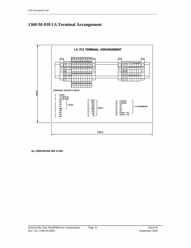
1360-M-039 I.S.Terminal Arrangement
Intrinsically Safe WindObserver Anemometer Page 21 Issue 03Doc. No. 1360-PS-0001 September 2002

Gill Instruments Ltd_______________________________________________________________________________________________________
1360-G-043 I.S. PCI Unit
Intrinsically Safe WindObserver Anemometer Page 22 Issue 03Doc. No. 1360-PS-0001 September 2002

Gill Instruments Ltd_______________________________________________________________________________________________________
9. TECHNICAL SPECIFICATION
9.1 SpecificationI.S. Rating - EuropeanFor use in Zone 0, 1 and 2 Areas.Rating EEx ia (BS EN 50 020)Gas Group IICTemp Class T5
Measurement CharacteristicsMeasurement velocity range 0 to 70m/sVelocity resolution 0.01m/sVelocity accuracy ±5% RMSDirection resolution 1 degreeDirection accuracy ± 4 degrees
Note: Accuracy specification applies from 5oC to 35oC and for wind incidence within±10o of horizontal.
Temperature CharacteristicsOperating -25oC to +60oCStorage -50oC to +75oC
Anem. ElectricalSupply 6 to 12V DCCurrent 30mA Peak
All circuits protected to 0.8 Joule
EnvironmentalAltitude 0 to 3000mHumidity 5 to 100% RHMoisture ingress IP65
EMCEmissions BS EN 50081-1:1992 (class B)Immunity BS EN 50082-1:1992
Material316 Stainless Steel
Intrinsically Safe WindObserver Anemometer Page 23 Issue 03Doc. No. 1360-PS-0001 September 2002

Gill Instruments Ltd_______________________________________________________________________________________________________
Serial InterfaceOne Tx RS422 channelOne Rx RS422 channel1200, 2400, 4800, 9600, 19200 and 38400 baudParity error check available (odd or even)Serial output rate 1 per second or 4 per second
PhysicalSize 380mm x 210mmWeight 2kg
ConnectorHirose, 20 way socketConnector pin Designation
1 Not Used2 RS422_TXB (+)3 RS422_TXA (-)4 RS422_RXB (+)5 RS422_RXA (-)6 Supply V+7 Not Used8 Not Used9 Not Used10 Not Used11 Not Used12 Not Used13 Not Used14 Supply V-15 Not Use16 Not Used17 Not Used18 Not Used19 Not Used20 Not Used
Intrinsically Safe WindObserver Anemometer Page 24 Issue 03Doc. No. 1360-PS-0001 September 2002

Gill Instruments Ltd_______________________________________________________________________________________________________
10. POWER AND COMMUNICATIONS INTERFACEThe Intrinsically Safe anemometer must be operated with the intrinsically safe power andcommunications interface (PCI).
10.1 PCIFor use with single intrinsically safe anemometers.
10.1.1 External ConnectionsEarth PostMains ConnectorAnemometer ConnectorRS232 ConnectionRS422 Connection
10.1.2 Electrical Power Requirements1) 100Vac - 120Vac, 10VA for the 115V switch position.2) 200Vac - 250Vac, 10VA for the 230V switch position.
10.1.3 Internal Supply Supply to the interface circuit 5V, 50mA
10.1.4 External SupplySupply via the intrinsically safe barrier 10.5V, 50mAInternal fuse 100mA
10.1.5 RS422 InterfaceStandard RS422 interface drivers are connected to the anemometer via zener barriers orgalvanic isolation. One is used for the TX pair and the other for the RX pair.
For Connector Pin and Cable Assignments please refer to Section 8, Drawing 1360-G-028.
10.1.6 Cable RequirementsAnemometerThe anemometer is supplied with a 3-Meter long 3 pair 24 AWG screened cable. Thisshould be terminated into an EExe approved junction box. The cable is 9mm in diameter,so a suitable gland should be fitted. The cable between the anemometer and the PCIshould be a 3 pair screened and / or armoured, and have a minimum of 0.75mm crosssectional area and a maximum of 2.5mm cross sectional area.
Do not attach the screen of the anemometer to earth at the junction box, it must beattached to terminals 19 and 20 of the PCI via the field cable screen.
If armour cable is used the armour must be connected to earth. DO NOT join to the cablescreen.
Intrinsically Safe WindObserver Anemometer Page 25 Issue 03Doc. No. 1360-PS-0001 September 2002

Gill Instruments Ltd_______________________________________________________________________________________________________
10.1.7 EnvironmentalHumidity 5 to 90% RHMoisture Ingress IP65
10.1.8 Material316 Stainless Steel
10.1.9 EMCEmissions BS EN 50081-1:1992Immunity BS EN 50082-1:1992
Intrinsically Safe WindObserver Anemometer Page 26 Issue 03Doc. No. 1360-PS-0001 September 2002

Gill Instruments Ltd_______________________________________________________________________________________________________
APPENDIX 1
SUMMARY OF ABBREVIATIONS USED IN THIS MANUAL
AC Alternating Current
ANEM Anemometer
ASCII American Standard Code for Information Interchange
CR Carriage Return
CSV Comma Separated Variable
CSA Cross Sectional Area
CTS Clear To Send
DC Direct Current
DCD Data Carrier Detect
DDD Direction parameter
DEG DEGrees
DSR Data Set Ready
DTR Data Terminal Ready
EEPROM Electrically Erasable Programmable Read Only Memory
EMC Electro-Magnetic Compatibility
ETX End of string character
FPM Feet Per Minute
GND GrouND
HEX Hexadecimal
HZ Hertz
IP65 Ingress Protection Classification
Intrinsically Safe WindObserver Anemometer Page 27 Issue 03Doc. No. 1360-PS-0001 September 2002

Gill Instruments Ltd_______________________________________________________________________________________________________
I.S Intrinsic Safety
K Kilometres per hour
Knots Nautical Measurement of speed
KM KiloMetre
KPH KiloMetres Per Hour
LF Line Feed
M3 Operating Mode 3
M4 Operating Mode 4
mA MilliAmperes
MPH Miles Per Hour
mm MilliMetres
ms MilliSecond
m/s Metres per Second
pc IBM PC or compatible computer
PCI Power and Communications Interface
POR Power On Reset
PROCOMM Terminal emulator software package
RH Relative Humidity
RMS Root Mean Squared
RS232 Communications standard
RS422 Communications standard
RTS Request To Send
RI Ring Initiate
Intrinsically Safe WindObserver Anemometer Page 28 Issue 03Doc. No. 1360-PS-0001 September 2002

Gill Instruments Ltd_______________________________________________________________________________________________________
RX Receive
SEC SECond
SRAM Static Random Access Memory
STX Start of string character
S/W SoftWare
TX Transmit
UV Cartesian Co-ordinate System
V Volts
V+ positive Voltage
V- negative Voltage
VA VoltAmperes
OPTIONAL EXTRAS
Custom software on application.
Intrinsically Safe WindObserver Anemometer Page 29 Issue 03Doc. No. 1360-PS-0001 September 2002

Gill Instruments Ltd_______________________________________________________________________________________________________
APPENDIX 2
PRODUCT APPROVALS
SIRA CERTIFICATION
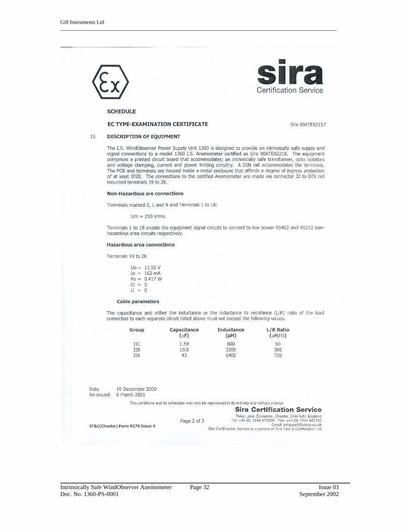
1. Certificate Number; Sira 00ATEX2217 for the IS WindObserver Power Supply Unit 13602. Certificate Number: Sira 00ATEX2218 for the model 1360 IS WindObserver Anemometer
Intrinsically Safe WindObserver Anemometer Page 30 Issue 03Doc. No. 1360-PS-0001 September 2002

Gill Instruments Ltd_______________________________________________________________________________________________________
Intrinsically Safe WindObserver Anemometer Page 31 Issue 03Doc. No. 1360-PS-0001 September 2002
Gill Instruments Ltd_______________________________________________________________________________________________________
Intrinsically Safe WindObserver Anemometer Page 32 Issue 03Doc. No. 1360-PS-0001 September 2002

Gill Instruments Ltd_______________________________________________________________________________________________________
Intrinsically Safe WindObserver Anemometer Page 33 Issue 03Doc. No. 1360-PS-0001 September 2002

Gill Instruments Ltd_______________________________________________________________________________________________________
Intrinsically Safe WindObserver Anemometer Page 34 Issue 03Doc. No. 1360-PS-0001 September 2002

Gill Instruments Ltd_______________________________________________________________________________________________________
Intrinsically Safe WindObserver Anemometer Page 35 Issue 03Doc. No. 1360-PS-0001 September 2002

Gill Instruments Ltd_______________________________________________________________________________________________________
Intrinsically Safe WindObserver Anemometer Page 36 Issue 03Doc. No. 1360-PS-0001 September 2002